Marcellus Shale Drilling and Hydraulic Fracturing; Technicalities and Controversies Kyle J Ferrar, MPH Center for Healthy Environments and Communities University of Pittsburgh Graduate School of Public Health Environmental and Occupational Health http://www.dcnr.state.pa.us/topogeo/education/es8.pdf
Transcript
Marcellus Shale Drilling and Hydraulic Fracturing; Technicalities and
Controversies
Kyle J Ferrar, MPH Center for Healthy Environments and Communities University of Pittsburgh Graduate School of Public Health Environmental and Occupational Health
I. Background II. Unconventional Development III. Mineral Rights IV. Permitting V. The Drilling Process VI. Hydrofracturing VII.Flowback Wastewater VIII.Processing, Transportation, and Storage
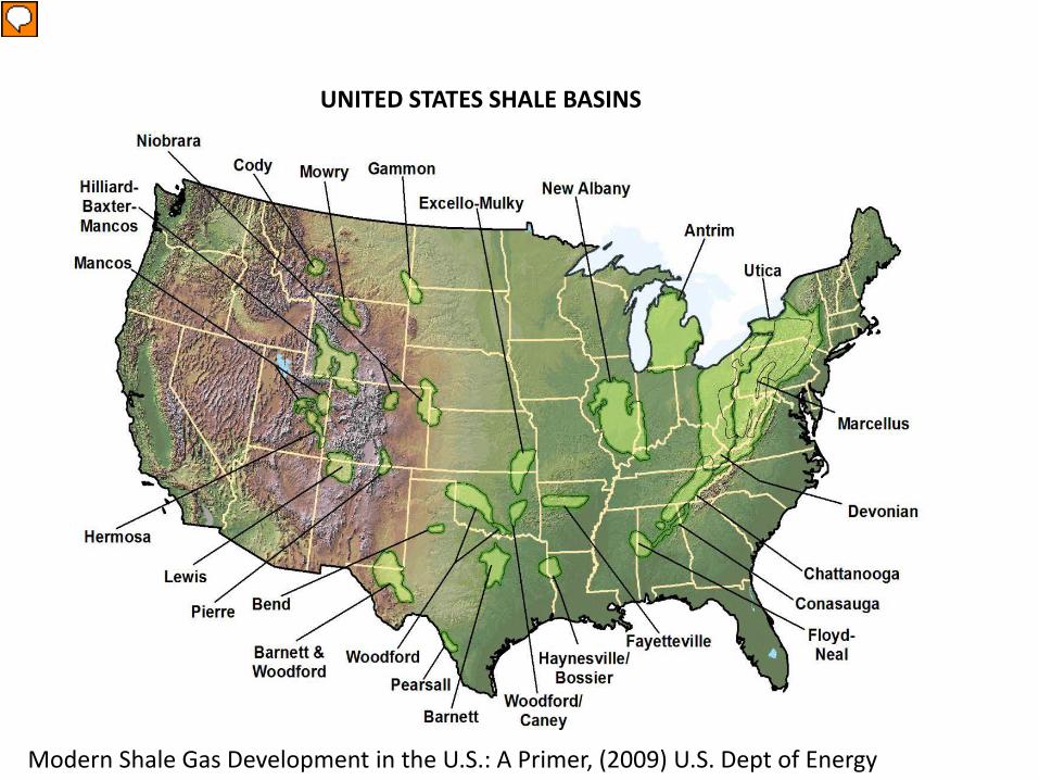
UNITED STATES SHALE BASINS
Modern Shale Gas Development in the U.S.: A Primer, (2009) U.S. Dept of Energy
Presenter
Presentation Notes
Gas trapped in these shale plays originated as prehistoric life millions of years ago. Devonian Shales are between about 350 and 420 myo Plants and primitive animals decomposing in ancient sea bed sediments produced natural gas as the mud layers were compressed into shale. Most of these deposit are located over a mile underground, and some close to 2 miles.
The conventional gas plays are geologically younger than the Devonian shales, but also show the legacy of the inland sea and ancient river delta that produced the shales.
Coal-bed methane extraction was developed throughout the 20th century, and continues today. There are thousands of wells in PA that are actively producing and thousands more that we have lost track of and just don’t know where they are. These wells were sunk quickly and without much effort. But often they did not produce more than enough to run an oven or a small houses furnace, and often they didn’t produce anything at all. In comparison, a Marcellus well may cost anywhere from X to y million dollars, but the shale play runs throughout the entirety of the state. No matter where you sink, yyou are almost gaurenteed to make a return on your investment. 16% in 1990 43% in 2006 (8.5/18.6 tcf) Projections by Energy Information Admin. by 2018 will be 50% of19.6 tcf by 2030 (EIA 2008) In comparison, the US uses about 23 TCF/year.
Where to Drill?
Harper, John A. (2008). The Marcellus Shale - An Old "New" Gas Reservoir in Pennsylvania. Pennsylvania Geology, Volume 38, Number 1. Pennsylvania Bureau of Topographic and Geologic Survey.
Shale Thickness Shale Depth
Presenter
Presentation Notes
Chesepeake Energy Corporation estimates that the Marcellus Shale contains 363 TCF of recoverable gas, but estimates from other geologists have been over 500 TCF. The shale gas is most plentiful where the carbonaceous material, or organic matter, is thickest. This explains the drilling in the northeastern region of PA. On the other hand it is cheaper to drill shallower wells, which explains all the activity in western PA, and the plans for Western NY state.
Marcellus Wells
Presenter
Presentation Notes
The trend follows the shallower region of the shale, and concentrate in the thicker shale.
Who and Where?
Gas Producing Counties • Armstrong County • Clearfield County • Crawford County • Fayette County • Indiana County • Jefferson County • McKean County • Mercer County • Westmoreland County • Venango County • Washington County
Active Companies in PA • Chesapeake Energy • CNX Gas • Exxon Mobil • Range Resources • XTO Energy
Presenter
Presentation Notes
Chesepeake Energy controls about half the market. In 2003, Range Resources was the first to find a promising gas flow from the Marcellus, and has now leased 1.2 million acres in PA. The hydrfracturing technology currently being used in the shale is so new that lifetime estimates and long term production values are not yet available.
Mineral Rights • Mineral • Landmen • Signing parties • Lawyers • Signing Bonus • Royalties • Lease Contracts • “Waiting on pipeline” clause • Severance Tax • Property Law
Presenter
Presentation Notes
Mineral Rights date back to the 1889, at the Drake Well, Titusville, Pa. The first successful oil well drilled in the U.S. Statewide signing bonuses are between $150 and $6,000/acre. 12.5 (or 1/8 the value) is the customary royalty percentage "Lease to me now or we will drill your neighbor's land and drain your gas without paying you a cent.“ According to the DEP: your only protection is if your oil or gas property is subject to the Oil and Gas Conservation Law. This law applies only to wells that penetrate 3,800 feet deep. When the Conservation Law is not in effect (as it rarely is with Marcellus wells), an operator is free to fracture the shale from a well on a leased property and pull gas from fractures that run under a neighboring, non-leased property (this is the "rule of capture"). In Pennsylvania the rules for natural gas sharing change at certain depths below the surface and at certain positions in the stratigraphic column. Disputes between the mineral rights owner and the surface rights owner usually arise at the time of mineral extraction. �These activities can require use of the surface and damage the surface owner's enjoyment of the property. Here is where the wording of the mineral rights agreement or lease agreement becomes very important. Legally intolerable Sept 7, PA Superior Court ruled that current law does not sufficiently address whether MS constitutes a mineral. A rule change in property law could create chaos. A new severance tax proposal gaining bipartisan support at 4.9% 362$ mil to 560$mil in 5 years. 28% to local gov, 28% to env programs, 44% to gen cauc In WV 5% at wellhead at 4.7c per 1,000 cubic feet Grace periods in LA and AK
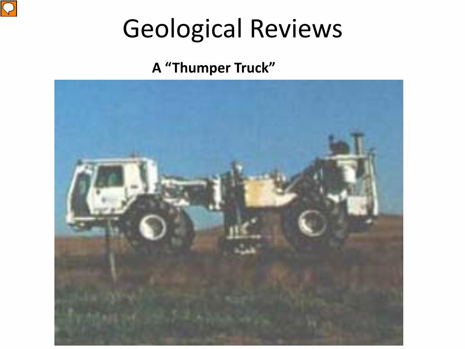
Geological Reviews A “Thumper Truck”
Presenter
Presentation Notes
Geologists review the subsurface environment using a number of techniques, such as taking advantage of wells and boreholes already in the area, as well as Remote-Sensing processes. Seismic Reflection – sensors place on ground surrounding a noise-making device. Soundwaves travel downward and horizontally, and are reflected back to the surface to the sensors. Different rock types reflect the waves differently.
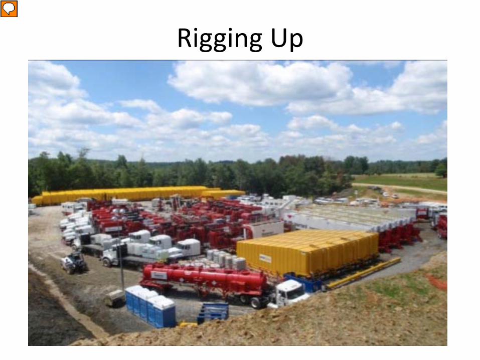
Rigging Up
Presenter
Presentation Notes
Permits obtained from PADEP by the gas industry Involves a water management plan, as well as erosion management Plan for pad development and drilling When land has been leased and the permit approved, the drillers prepare by “rigging up” the site. That includes bulldozing level ground and building access roads. Well pads need to be 5-8 acres in size. The footprint remains as long as the well is still active, and a well may be fractured a number of times.
Drilling • The Drill String
– Diesel Powered – Drilling Bit – Drilling Pipe
• Air Rotary Drilling Rig • Hydraulic Rotary Drilling
1. Drilling cuttings Rig – Drill cuttings are forced up through the hollow drilling pipe by compressed air Each well produces about 1,000 tons of drilling waste (mud and rock) that may be contaminated with heavy metals and Naturally occurring radioactive materials (NORM), as well as slicking chemicals added to the drilling muds. 2. Horizontal 30’ /495lbs = over 350 pieces, that’s a lot of junctions It is possible to drill up to 5000 feet horizontally from the vertical well (http://www.srbc.net/whatsnews/doc) Each well can access gas trapped beneath 200-400 acres Multiple horizontal wells can be drilled from one drilling pad. Necesssary since the formation is rather thin, just about 50m thick. 3. telescoping They will go in with three different sizes from Surface, Intermediate, and finally production casing. When they cement the area between the outside of the casing to the inside of the borehole, they will pump cement from the bottom up in order to avoid having voids in the cement. They start with a fixed volume of cement based on the size of the the borehole/casing displacement calculations. If they start to get a rise in pressure before they allotted amount of cement is used they will try a few techniques that allows them to pressurize the cement therefore pushing the air out and filling the void. If they are not satisfied with those results they can go back into the casing to perform a seismic test which will tell them where the voids are. If the results do not meet the industry standard they will pull all casing out of the hole, ream the borehole and then re-case and cement the hole.
The production string” is the final casing installed in the well. Shots are detonated in 100m sections creating perforations. Perforations are shot through the casing and the cement. The shale is tight or compressed. The hydrofracturing fluid (water sand and lubricants, and acid) is pumped into the well using diesel compressors under extremely high pressure (up to 15,000 psi).
Aquifer Contamination • From the surface • From the casing
– Pipeline Production – Radiographic imaging – Pipe Dope – Voids in the cement – Seismic Tests – Pressure Tests
When groundwater contamination occurs, it may happen three different ways. First - hydrofracturing waters and wastewaters at the surface may be spilled and leach into groundwater Second – The casing at the aquifer may be faulty, and leak. This can happen for a number of reasons. The porosity of the aquifer layer is substantially greater than the dry layers. It is more permeable. This can effect the quality of the casing. If the casing was not properly welded during production, the welds will rust and split. Radiographic imaging screens the welds for imperfections and is a best practice that needs to implemented. Pipe Dope is a lock tight. - Pipes need to be pieced together to the right torque. If cement is not the correct thickness, the casing can easily rust through. A fullproof method for pressure testing has not yet been implemented Pressure tests are conducted after the well is drilled to the final depth and before hydrofracturing. To protect freshwater aquifers, a cement casing is created, by pumping concrete through the annulus and filling the borehole from the bottom to ensure complete circulation.
Methane Migration
Presenter
Presentation Notes
PADEP Research on hydraulically fractured horizontal wells can give insight as to the issues that will be realized as we continue to scale up production. Methane migration can be detected by monitoring wellhead pressures. The largest source of methane loss is due to over-pressuring to levels above normal formation pressures. Unfortunately, this is also the least understood process of methane migration. Existant theories include thermal expansion of waters in de-watered shales causing pressure in the annulus to rise. If the gas is not allowed to escape the pressure differential will build up within the annulus. To deal with this, wells are flared prior to production, to lower pressure. Cementing the entire depth of the anulus also reduces this risk. Due to the low permeability of shales, overpressuring may not be the greatest risk, so all 4 of these pathways need to be monitored.
“Frac Water”
Impoundment • Flow-back Water • Produced Water • Proprietary chemicals • Up to 5 million gallons per “frac” • Water sources • Water transported via tankers • Open pits to closed tankers • Disposal options
Presenter
Presentation Notes
1. Fracturing fluid additives include clay control agents, gel stabilizers, surfactants, foamers, gel breakers, fluid loss additives, friction reducers, scale inhibitors, bactericides, and pH control agents Each tanker holds 4,500 gallons, so it requires several hundred to thousands of truck trips. 2. Excessive groundwater and surface water usage Lowering freshwater aquifers and surface water sources. Each fracked well uses about 5 million gallons of water. 3. The formation brines often contain relatively high concentrations of sodium, chloride, bromide, and other inorganic constituents, such as arsenic, barium, other heavy metals, and radionuclides that significantly exceed drinking water standards (Harper, 2008). 4. Groundwater contamination from flowback and produced water that contain toxic metals/elements, organic compounds (BETX), and elevated levels of radionuclides from the shale formation itself. 5. Inadequate treatment and inappropriate disposal of brine water into surface water, which adds toxic anions and cations and increases TDS levels in drinking water supplies. reports of high salinity in some Appalachian rivers have been linked to the disposal of Marcellus Shale brines (Water and Wastes Digest, 2008). At the beginning of 2011, there were over 60 wastewater treatment sites permitted to accept the wastewaters, the majority municipal wastewater treatment plants
Ambient Air Sampling
Presenter
Presentation Notes
From the wellhead, natural gas is pumped through condensors, small compressors, and the produced water is captured in condensate tanks. When natural gas escapes from leaks in this equipment, and the vent located on the top of the condensate tank, it is not just methane. The natural gas is full of other volatile organic compounds (VOC’s) such as benzene, as well as diesel exhausts. An issue that requires more attention is the emission of ozone precursors and the potential for ozone hotspots on and near wellpads. The map above shows Marcellus well sites, as of May 2011 as well as the location of the DEP and EPA ambient air monitors that monitor Ozone. To even understand the impact on ozone, the network needs to be enlarged.
There are three types of pipelines First, form the wellhead, the gathering lines bring the natural gas to the processing, or “sweetening” plant. A complex gathering system can include 100’s of wells. These are the intrastate pipelines At the processing plant, located in the same region as the drilling, the gas is separated and purified Processes include oil and condensate removal, water removal, removal of Sulfur and carbon dioxide, and separation of natural gas liquids. Interstate pipelines transfer the gas at high pressure and low volume, from low to high demand areas. Compressor stations are located periodically along the pipelines to maintain the high pressures. Valves and meter stations control and monitor the flow. The distributions system then relay the natural gas to the consumer.
New Drilling Regulations • Blow Out Prevention (BOP) devices • Well Construction, casing and cementing
standards. • Surface Casing • Casing centralizers • Casing and cementing plan • Pressure Testing • Cement testing • Zone of critical cement • Quarterly monitoring program
Presenter
Presentation Notes
There have been improvements of regulations. As of March, new standards have been enacted by the DEP for drilling and hydrofracturing practices. There have been regulatory improvements: To prevent blowouts, such as the EOG Resources accident in Clearfield County, June 3, 2010, drillers are now required to use two pressure barriers. The equipment must be tested before use, and immediately after installation. And a certified well supervisor has to be present during the post-frac operations. Surface casing hole must be drilled using air, freshwater, or freshwater-based drilling fluid Casing centralizers must be installed every 150 feet An extensive casing and cementing plan is now required with established methodologies for identifiying the deepest horizon of freshwater. The PADEP may require pressure testing if there is a loss of circulation of the cement. For the casing, a passing pressure test is holding the maximum anticipated pressure for 30 minutes with no more than a 10% change in pressure. In a conservative system, there should not be any pressure loss. Cement with a min pressure rating of 350 p.s.i., and 1200 for bottom 300 ft of surface casing Monitoring provisions Pressure monitoring associated with production casing Pressure monitoring in annular space associated with production casing Pressure monitoring at relevant casing seat Checking well fluid level in production casing Corrosion and equipment deterioration survey Monitoring for leaking gas Clear methodology for addressing over-pressured wells Flexibility for Department to require additional testing This is a good start, but there are many more techniques, a few of which I have mentioned, that should be industry standards.
Beyond the Marcellus
http://geology.com/articles/marcellus-shale.shtml
Presenter
Presentation Notes
Although the Marcellus shale layer is the current focus of unconventional production, a few thousand feet deeper is the Utica Shale. The commercial value has already been realized, since it is thicker and more geographically extensive than the Marcellus. When production from Marcellus Shale wells start to decline, the wells will be drilled deeper and re-stimulated The current infrastructure of drill pads, right-of-ways, pipelines, permit data, and other investments will reduce development costs. But by the time these wells are redrilled and re-stimulated, the casing and cement will have aged and degraded. Lawmakers and regulatory agencies need to anticipate the issues that will accompany the established, but