20
+ - MARSURF PERTHOMETER S2

+-
MARSURF PERTHOMETER S2

-
MarSurf . Sur face Measur ing Ins t ruments and Sys tems
FROM THE THUMBNAIL TEST…
… TO MARSURF.
Wherever surface structures influence the function, processing or appearance of components or products, careful testing is
essential . But how can surfaces be tested? At the beginning of the 20th Century, experts still had to test by eye and touch. A
practiced eye can detect features in the μm range, and even the much maligned thumbnail test delivered perfectly acceptable
results. Now however, we live in an age of exchangeable parts, fits and internationalization, where subjective tests like this are
no longer adequate. Today, computer-aided measuring instruments provide objective data. Measurement and evaluation have
become considerably easier. For decades, Mahr has been a worldwide pioneer in this area, as demonstrated by the company's
numerous innovations and patented solutions in the field of surface roughness metrology. The interplay between the stylus,
drive and measuring setup plays a key role in influencing the quality of surface measurement tasks. This is where Mahr's core
expertise comes in, as demonstrated by the company's numerous innovations and patented solutions. Over this time, we have
succeeded in perfecting the stylus method, which is now in widespread use throughout the world. We can meet even the most
demanding requirements for non-contact measurement, e.g. where extremely soft materials or ultra-short measuring times are
involved, thanks to the range of optical sensors offered in the MarSurf product family. Developed with Mahr quality, expertise
and know-how, MarSurf is the solution for all your surface metrology needs.

+
MarSurf . Sur face Measur ing Ins t ruments and Sys tems
MarSurf. Perthometer S2
Stat ionary and Mobi le Surface Measur ing Instruments 4
Perthometer S2 5
Perthometer S2 with PZK for Mobi le Use 6
Perthometer S2 with PZK for Stat ionary Use 7
Perthometer S2 with GD 25 for Mobi le Use 8
Perthometer S2 with GD 25 for Stat ionary Use 9
Perthometer S2 with PGK 120 for Stat ionary Use 10
MarSurf XR 20 Evaluat ion Software for MarSurf S2 12
Perthometer S2 . Technica l Data 13
Accessor ies
PZK Dr ive Unit 14
GD 25 Dr ive Unit 15
PGK 120 Dr ive Unit 16
MFW-250 Sk id less P ick-Up 18
Pick-Ups for Perthometer Surface Measuring Instruments 19

-
4 MarSurf . Sur face Measur ing Ins t ruments and Sys tems
MarSurf. Surface Measuring Instruments for Production AreaSURFACE MEASURING STATION FOR MANUFACTURING ENVIRONMENTS AND INSPECTION ROOMS
Mahr stationary surface measuring instruments for manufacturing environments are high-performance and user-friendly.
Their flexibility when performing evaluation and documentation makes them ideal for the increasingly demanding tasks on the
shop floor. Standardized roughness, waviness and profile parameters are evaluated in accordance with international standards
like ISO, J IS and ASME. Skidless pick-ups with easily exchangeable stylus tips support rapid adaptation to frequently changing
measuring tasks.

+
MarSurf . Sur face Measur ing Ins t ruments and Sys tems 5
Perthometer S2
Surface measuring instrument for stationary and mobile use
The Perthometer S2 evaluating instrument stands out forthe following features:
• Roughness and waviness measurements according to currentstandards (DIN EN ISO 3274, e. g. band-pass filter)
• Its low weight (despite the included powerful rechargeablebattery)
• A large high-resolution graphics display to indicate results and profiles
• Easy operation based on the automatic teller principle and large operating elements
• Quick documentation via the integrated high-resolutionthermal printer
• Storage facility on PCMCIA memory card for measuring programs, results and profiles
• Add-on program S2Prog for an easy creation of measuringprograms
Features • Extensive, easily applicable software functions, such as- Automatic function for setting standardized filters and
traversing lengths- Monitoring of calibration and maintenance intervals- ARC function for circle arc elimination- Dynamic and static calibration routines- Evaluation of more than 41 parameters according to DIN EN
ISO, JIS, ASME, MOTIF, R, W, P and D profile as well as characteristic curves MRC/ADC at different scalings
- Variable selection of filters and traversing lengths- Tolerance monitoring with audible and visual signals- Blocking of instrument settings for preventing unintentional
modifications plus possibility of password protection- Integrated statistical functions- Function keys for individual functions- Easy call-up and printout of measuring records and individual
functions• Software updates via PCMCIA memory card• SPC interface for integrating the S2 into the production
processes• RS 232 interface for data transfer and remote control
• Perthometer S2 Order No. 6250803

-
6 MarSurf . Sur face Measur ing Ins t ruments and Sys tems
Perthometer S2 Mobile Surface Texture Measuring Station with PZK
Roughness and waviness measurements on large workpieces or on the shop floor
Perthometer S2. Mobile surface texture measuring stationwith PZK drive unit
The characteristics of the Perthometer S2 evaluation instrumentare described on page 5.
Of particular importance for mobile use:
• Weight < 3 kg (6.6 lbs)• Rechargeable battery for more than 1,000 measurements• Memory card for storing results, profiles, measuring programs
Features PZK Drive Unit
Measuring Station Components
• A special carrying case serves for safe storage and transport ofthe measuring station
The measuring station consists of the following components:
• Perthometer S2 Order No. 6250803• PZK drive unit (set) Order No. 6910301• Carrying case Order No. 6851214
Options
• MarSurf XR 20 evaluation software Order No. 6299009• PRN 10 roughness standard
with certificate Order No. 6820420
• PZK drive unit with integrated datum plane for precisemeasurements up to 20 mm (.787 in) tracing length.
• With integrated skidless pick-up MFW (low traversing force ofapprox. 0.7 mN; stylus 2 μm (80 μin)/90° for mobile roughnessand waviness measurements
• Cost-saving modular pick-up with exchangeable probe arms:measuring range ± 250 μm (± 10,000 μin)

+
MarSurf . Sur face Measur ing Ins t ruments and Sys tems 7
PZK drive unit with integrated datum plane for precisemeasurements up to 20 mm (.787 in) tracing length.
• With integrated skidless pick-up MFW (low traversing force ofapprox. 0.7 mN; stylus 2 μm (80 μin)/90° for mobile roughnessand waviness measurements
• Cost-saving modular pick-up with exchangeable probe arms:measuring range ± 250 μm (± 10,000 μin)
Perthometer S2. Stationary surface texture measuring sta-tion with PZK drive unit
The characteristics of the Perthometer S2 evaluation instrumentare described on page 5.
Perthometer S2 also includes the following interesting features:• Display of the pick-up signal on a bar graph• Numerical input as on a cell phone• Date and time of measurement• Adjustable horizontal and vertical scale for the profile• Convenient display of the results incl. parameter and profile
presentation
Features
Measuring Station Components
The measuring station consists of the following components:
• Perthometer S2 Order No. 6250803• PZK drive unit (set) Order No. 6910301• ST-G measuring stand
with T-slot Order No. 6710807• PZK mounting device for
measuring stand Order No. 6851328
Options:• XY table CT 120 Order No. 6710529
Roughness and waviness measurements on small and medium-sized workpieces
Options
ST-G Measuring Stand
• With granite plate, 500 x 300 mm (15.75 in x 9.84 in) (L x W) and 10 mm T-slot in the center
• Column with height adjustment up to 300 mm (11.81 in) for thedrive unit
• MarSurf XR 20 evaluation software Order No. 6299009• PRN 10 roughness standard
with certificate Order No. 6820420• XY table CT 120 Order No. 6710530
PZK Drive Unit
Perthometer S2 Stationary Surface Texture Measuring Station with PZK

-
MarSurf . Sur face Measur ing Ins t ruments and Sys tems8
• GD 25 drive unit with integrated datum plane for precisemeasurements up to 25.4 mm (1 in) traversing length
• Residual Rz values < 30 nm (1.18 μin) at a tracing speed of 0.1 mm/s (.00394 in/s)
• Suitable for horizontal, vertical and upside down measurements
Perthometer S2. Mobile surface texture measuring stationwith GD 25 drive unit.
The characteristics of the Perthometer S2 evaluation instrumentare described on page 5.
• In addition, the S2 controls the vertical axis of drive unit GD 25for an automatic positioning of the pick-up
• Motor-driven height adjustment within a range of 4 mm (.158 in)• Motor-driven pick-up zero setting (patented) for an easy set-up
and start of measurement
Features
Measuring Station Components
A special carrying case serves for safe storage and transport ofthe measuring station.The measuring station consists of the following components:
• Perthometer S2 Order No. 6250803• GD 25 drive unit Order No. 6721006• MFW skidless pick-up set Order No. 6111404• Carrying case Order No. 6851214
Options
MFW Skidless Pick-up Set
• Measuring range ± 250 μm (± 10,000 μin) (with double lengthtracing arm ± 500 μm (± 20,000 μin))
• Low measuring force approx. 0.7 mNLow linearity deviation < 1 %
• With three exchangeable standard tracing arms (stylus 2 μm (80 μin) /90°) for the most frequent applications
• Tracing arm protection and skid• Cost-saving modular pick-up for exchangeable tracing arms
• MarSurf XR 20 evaluation software Order No. 6299009• PRN 10 roughness standard
with certificate Order No. 6820420• XY table CT 120 Order No. 6710529
GD 25 Drive Unit
Perthometer S2 Mobile Surface Texture Measuring Station with GD 25
Roughness and waviness measurements on large workpieces or on the shop floor

+
MarSurf . Sur face Measur ing Ins t ruments and Sys tems 9
• GD 25 drive unit with integrated datum plane for precisemeasurements up to 25.4 mm (1 in) tracing length.
• Residual Rz values < 30 nm (1.18 μin) at a traversing speed of0.1 mm/s (.00394 in/s)
• Suitable for horizontal, vertical and upside down measurements
Perthometer S2. Stationary surface texture measuring sta-tion with GD 25 drive unit.
The characteristics of the Perthometer S2 evaluation instrumentare described on page 5.
• In addition, the S2 controls the vertical axis of drive unit GD 25for an automatic positioning of the pick-up
• Motor-driven height adjustment within a range of 4 mm (.158 in)• Motor-driven pick-up zero setting (patented) for an easy set-up
and start of measurement
Features
Measuring Station Components
The measuring station consists of the following components:
• Perthometer S2 Order No. 6250803• GD 25 drive unit Order No. 6721006• MFW skidless pick-up set Order No. 6111404• ST-G measuring stand with T-slot Order No. 6710807• GD 25 mounting device for
measuring stand Order No.. 6851325• XY table CT 120 Order No. 6710529
Options: PPS parallel vice Order No. 6710604
MFW Skidless Pick-up Set
• Measuring range ± 250 μm (± 10,000 μin) (with double lengthtracing arm ± 500 μm (± 20,000 μin))
• Low measuring force approx. 0.7 mN• Low linearity deviation < 1 %• Tracing arm protection and skid• With three exchangeable standard tracing arms (stylus 2 μm
(80 μin)/90°) for the most frequent applications• Cost-saving modular pick-up for exchangeable tracing arms
GD 25 Drive Unit
Roughness and waviness measurements on small and medium-sized workpieces
Perthometer S2 Stationary Surface Texture Measuring Station with GD 25
• With granite plate, 500 x 300 mm (15.75 in x 9.84 in) (L x W) and 10 mm T-slot in the center
• Column with height adjustment up to 300 mm (11.81 in) for thedrive unit
ST-G Measuring Stand

-
10 MarSurf . Sur face Measur ing Ins t ruments and Sys tems
Perthometer S2 Stationary Surface Texture Measuring Station with PGK 120
• PGK 120 drive unit with integrated datum plane for precise meas-urements up to 120 mm (4.724 in) tracing length.
• Residual Rz values < 30 nm (1.18 μin) at a traversing speed of 0.1 mm/s (.00394 in/s)
• Low straightness deviation of the X-axis < 0.3 μm/120 mm(12 μin/4.724 in)
Perthometer S2. Stationary surface texture measuring sta-tion with PGK 120 drive unit.
The characteristics of the Perthometer S2 evaluation instrumentare described on page 5.
• In addition, the S2 controls the vertical axis of drive unit PGK 120 for an automatic positioning of the pick-up
• Manual height adjustment within a range of 50 mm (1.969 in)• Motor-driven pick-up zero setting within a range of 22 mm
(.866 in) (patented) for an easy set-up and start of measurement
Measuring Station Components
The measuring station consists of the following components:
• Perthometer S2 Order No. 6250803• PGK 120 drive unit Order No. 6721010• MFW skidless pick-up set Order No. 6111404• Compact measuring station Order No. 6851906• Small XY table Order No. 6851909
Options
MFW Skidless Pick-up Set
• MarSurf XR 20 evaluation software Order No. 6299009• PRN 10 roughness standard
with certificate Order No. 6820420
PGK 120 Drive Unit
• With small XY table• The design provides for a small measuring circle so that
vibrations are reduced to a minimum• Ideally suited for series measurements requiring high
repeatability and reproducibility
Compact Measuring Station
Features
• Measuring range ± 250 μm (± 10,000 μin) (with double lengthtracing arm ± 500 μm (± 20,000 μin))
• Low measuring force approx. 0.7 mN• Low linearity deviation < 1 %• Tracing arm protection and skid• With three exchangeable standard tracing arms (stylus 2 μm
(80 μin)/90°) for the most frequent applications• Cost-saving modular pick-up for exchangeable tracing arms
Roughness and waviness measurements on small workpieces

+
MarSurf . Sur face Measur ing Ins t ruments and Sys tems 11
Perthometer S2. Stationary surface texture measuring sta-tion with PGK 120 drive unit.
The characteristics of the Perthometer S2 evaluation instrument aredescribed on page 5.
• The PGK 120 drive unit can also be mounted on the measuringstand. A control panel enables motor-driven height adjustmentwithin a range of 25 mm to 410 mm (.984 in to 16.14 in) (optionally up to 660 mm (26 in)). The mounting device enablesthe drive unit to be swiveled so that measurements can be carriedout within a range of +30° to –45°.
Features
Measuring Station Components
The measuring station consists of the following components:
• Perthometer S2 Order No. 6250803• PGK 120 drive unit Order No. 6721010• MFW skidless pick-up set Order No. 6111404• ST 500 measuring stand Order No. 6710250• PGK 120 mounting device for
ST 500/750 Order No. 6851361• Control panel 230 V* Order No. 6851322• XY table CT 200 Order No. 6710530
*115 V on request
Roughness and waviness measurements on large, complex workpieces
Options
ST 500 Measuring Stand
• MarSurf XR 20 evaluation software Order No. 6299009• PRN 10 roughness standard
with certificate Order No. 6820420• XY table CT 120 Order No. 6710529
PGK 120 Drive Unit
Perthometer S2 Stationary Surface Texture Measuring Station with PGK 120
• PGK 120 drive unit with integrated datum plane for precise meas-urements up to 120 mm (4.724 in) traversing length
• Residual Rz values < 30 nm (1.18 μin) at a traversing speed of 0.1 mm/s (.00394 in/s)
• Low straightness deviation of the X-axis < 0.3 μm/120 mm(12 μin/4.724 in)
MFW Skidless Pick-up Set
• Measuring range ± 250 μm (± 10,000 μin) (with double lengthtracing arm ± 500 μm (± 20,000 μin))
• Low measuring force approx. 0.7 mN• Low linearity deviation < 1 %• Tracing arm protection and skid• With three exchangeable standard tracing arms (stylus 2 μm
(80 μin)/90°) for the most frequent applications• Cost-saving modular pick-up for exchangeable tracing arms
• With granite plate, 700 x 550 mm (27.6 in x 21.7 in) (L x W) • Column with height adjustment up to 500 mm (19.7 in) for the
drive unit

-
12 MarSurf . Sur face Measur ing Ins t ruments and Sys tems
• More than 65 parameters may be selected for R, P and W profiles as per ISO / JIS or MOTIF
• Tolerance monitoring and statistics for all parameters• Fast creation of Quick & Easy measuring programs using Teach-In
mode• Comprehensive logging• Simulation mode to help users familiarize themselves with the
system quickly• Numerous measuring station configurations for customized
applications• Different user levels can be set up• Printout of a A 4 form via a PC printer• Archiving of the measured profiles on PC or laptop
Perthometer S2. Stationary surface texture measuring sta-tion with PGK 120 drive unit and evaluation software.
The MarSurf XR 20 workstation is based on the PC measuringsystem software.The software enables the measuring result to be archived anddocumented very easily. Here, an S2 unit is controlled by a PC, i.e.the measuring conditions are set and the measurement ist starteton the PC or laptop.
Clear icons and a comprehensive online help make using thispowerful software very easy. Decades of surface metrology expe-rience are combined with state-of the-art and future-focused technologies.
The workstation supports WINDOWS 2000 and WINDOWS XP.Data transmission is performed via an RS 232 cable between S2 unit and PC. For accessing the software, a USB dongle and alicense file are required.
Description
Accessories
• MarSurf XR 20 evaluation software• USB dongle• Floppy disk 3.5" with license file• RS 232 cable (2 m)
Order No. 6299009
Features
Archiving and documenting made easy
MarSurf XR 20 Evaluation Software for MarSurf S2
+
MarSurf . Sur face Measur ing Ins t ruments and Sys tems 13
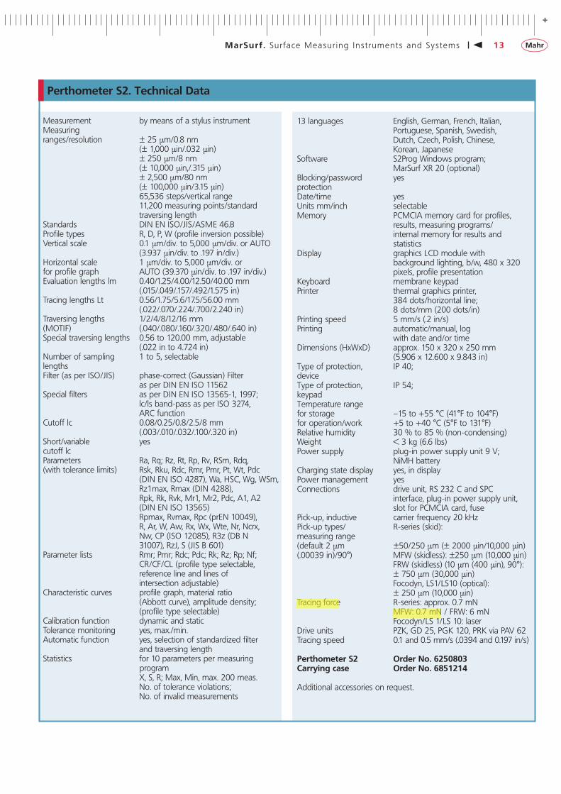
Perthometer S2. Technical Data
Measurement by means of a stylus instrumentMeasuringranges/resolution ± 25 μm/0.8 nm
(± 1,000 μin/.032 μin)± 250 μm/8 nm(± 10,000 μin,/.315 μin)± 2,500 μm/80 nm(± 100,000 μin/3.15 μin)65,536 steps/vertical range11,200 measuring points/standard traversing length
Standards DIN EN ISO/JIS/ASME 46.BProfile types R, D, P, W (profile inversion possible)Vertical scale 0.1 μm/div. to 5,000 μm/div. or AUTO
(3.937 μin/div. to .197 in/div.)Horizontal scale 1 μm/div. to 5,000 μm/div. orfor profile graph AUTO (39.370 μin/div. to .197 in/div.)Evaluation lengths lm 0.40/1.25/4.00/12.50/40.00 mm
(.015/.049/.157/.492/1.575 in)Tracing lengths Lt 0.56/1.75/5.6/17.5/56.00 mm
(.022/.070/.224/.700/2.240 in)Traversing lengths 1/2/4/8/12/16 mm(MOTIF) (.040/.080/.160/.320/.480/.640 in)Special traversing lengths 0.56 to 120.00 mm, adjustable
(.022 in to 4.724 in)Number of sampling 1 to 5, selectablelengthsFilter (as per ISO/JIS) phase-correct (Gaussian) Filter
as per DIN EN ISO 11562Special filters as per DIN EN ISO 13565-1, 1997;
lc/ls band-pass as per ISO 3274, ARC function
Cutoff lc 0.08/0.25/0.8/2.5/8 mm(.003/.010/.032/.100/.320 in)
Short/variable yescutoff lcParameters Ra, Rq; Rz, Rt, Rp, Rv, RSm, Rdq, (with tolerance limits) Rsk, Rku, Rdc, Rmr, Pmr, Pt, Wt, Pdc
(DIN EN ISO 4287), Wa, HSC, Wg, WSm,Rz1max, Rmax (DIN 4288),Rpk, Rk, Rvk, Mr1, Mr2, Pdc, A1, A2(DIN EN ISO 13565)Rpmax, Rvmax, Rpc (prEN 10049),R, Ar, W, Aw, Rx, Wx, Wte, Nr, Ncrx,Nw, CP (ISO 12085), R3z (DB N 31007), RzJ, S (JIS B 601)
Parameter lists Rmr; Pmr; Rdc; Pdc; Rk; Rz; Rp; Nf;CR/CF/CL (profile type selectable,reference line and lines of intersection adjustable)
Characteristic curves profile graph, material ratio(Abbott curve), amplitude density;(profile type selectable)
Calibration function dynamic and staticTolerance monitoring yes, max./min.Automatic function yes, selection of standardized filter
and traversing lengthStatistics for 10 parameters per measuring
programX, S, R; Max, Min, max. 200 meas.No. of tolerance violations;No. of invalid measurements
13 languages English, German, French, Italian,Portuguese, Spanish, Swedish, Dutch, Czech, Polish, Chinese, Korean, Japanese
Software S2Prog Windows program;MarSurf XR 20 (optional)
Blocking/password yesprotectionDate/time yesUnits mm/inch selectableMemory PCMCIA memory card for profiles,
results, measuring programs/internal memory for results andstatistics
Display graphics LCD module withbackground lighting, b/w, 480 x 320pixels, profile presentation
Keyboard membrane keypadPrinter thermal graphics printer,
384 dots/horizontal line;8 dots/mm (200 dots/in)
Printing speed 5 mm/s (.2 in/s)Printing automatic/manual, log
with date and/or timeDimensions (HxWxD) approx. 150 x 320 x 250 mm
(5.906 x 12.600 x 9.843 in)Type of protection, IP 40;deviceType of protection, IP 54;keypadTemperature rangefor storage –15 to +55 °C (41°F to 104°F)for operation/work +5 to +40 °C (5°F to 131°F)Relative humidity 30 % to 85 % (non-condensing)Weight < 3 kg (6.6 lbs)Power supply plug-in power supply unit 9 V;
NiMH batteryCharging state display yes, in displayPower management yesConnections drive unit, RS 232 C and SPC
interface, plug-in power supply unit,slot for PCMCIA card, fuse
Pick-up, inductive carrier frequency 20 kHzPick-up types/ R-series (skid):measuring range(default 2 μm ±50/250 μm (± 2000 μin/10,000 μin)(.00039 in)/90°) MFW (skidless): ±250 μm (10,000 μin)
FRW (skidless) (10 μm (400 μin), 90°):± 750 μm (30,000 μin)Focodyn, LS1/LS10 (optical):± 250 μm (10,000 μin)
Tracing force R-series: approx. 0.7 mNMFW: 0.7 mN / FRW: 6 mNFocodyn/LS 1/LS 10: laser
Drive units PZK, GD 25, PGK 120, PRK via PAV 62Tracing speed 0.1 and 0.5 mm/s (.0394 and 0.197 in/s)
Perthometer S2 Order No. 6250803Carrying case Order No. 6851214
Additional accessories on request.

-
14 MarSurf . Sur face Measur ing Ins t ruments and Sys tems
PZK Drive Unit
PZK drive unit with integrated pick-up
This Perthometer system consists of the small, handy PZK drive unitand the integrated inductive MFW pick-up. The tracing arm can beexchanged in a flash. The built-in datum plane enables not onlystandard skidded, but also skidless measurements.The well-known advantages of the MFW pick-up are the largemeasuring range, a high linearity and resolution. The measuringforce, the design of the stylus tip and all technical details corre-spond to DIN/ISO standards.
The traversing length setting is performed on the Perthometer. Afterthe measurement, the pick-up automatically returns to its initialposition.
Hand-held support with height and inclination adjustment
Among other things, the PZK set includes a hand-held supportwhich makes the PZK system universally applicable:
The prism on the bottom side of the hand-held support enablesmeasuring on plane and cylindrical workpieces.For measuring stand operation, the support can be directly fixed tothe mounting device on the measuring stand.In case of skidless tracing, two generously dimensioned knobsensure sensitive and exact adjustment of both height and inclina-tion. The positioning is facilitated by the pick-up height and inclina-tion values being displayed on the Perthometer.
For skidded tracing, the standard tracing arm protection is ex-changed for one with a skid.
Features
PZK set Order No. 6910301consisting of:
Hand-held support with heightand inclination adjustment Order No. 6850734PZK drive unit with integratedinductive pick-up Order No. 6721101Tracing arm protection Order No. 6851815Tracing arm protection with skid Order No. 6851814Tracing arm cranked by 5.5 mm(.197 in), 2 μm (80 μin), 90° Order No. 6851816
Universal application is ensured by the integrated MFW pick-up andthe easily exchangeable tracing arms. In addition, further standardtracing arms of the MFW program are available for special meas-uring tasks.
Technical Data
Accessories
An extensive range of accessories makes sure the PZK drive unit can be used for many different applications, e.g. measurements oncylinders with a dia. larger than 14 mm (.551 in) due to aPair of vee-plates Order No. 6850537
or measurements on small cylindrical workpieces with a dia. largerthan 2 mm (.0787 in) using aFront vee-block Order No. 6850536
PZK mounting device for measuring stand ST-D, ST-F, ST-G Order No. 6851328
PZK drive unitTraversing length up to 20 mm (.787 in)Traversing direction longitudinalMeasuring range ± 250 μm (± 10,000 μin)Dimensions dia. 24 mm (.945 in),
length approx. 120 mm (4.72 in)Traversing speed 0.1 mm/s or 0.5 mm/s
(.00394 in/s or .0197 in/s)Measuring position anyStraightness deviation 0.35 μm/20 mm (13.78 μin/.787 in)
Hand-held supportHeight adjustment range 4 mm (.158 in)Inclination adjustment range ± 20 μm/mm (± 20,000 μin/25,4 in)Dimensions (L x W x H) 81.5 mm x 32 mm x 56.5 mm
(3.21 in x 1.26 in x 2.22 in)with standard front plates 93.5 mm x 34 mm x 60 mm
(3.68 in x 1.34 in x 2.36 in)Positioning accuracyof the height adjustment 1 μm/degree (39.37 μin/degree) of the inclination adjustment 0.02 μm/mm/degree

+
MarSurf . Sur face Measur ing Ins t ruments and Sys tems 15
GD 25 Drive Unit
The GD 25 with its integrated datum plane stands out for itssmooth traverse and low-vibration design. The housing, the bottomof which is in the form of a prism, is compact and robust. The GD 25 features a motor-driven height adjustment for loweringand lifting the pick-up and for setting it to zero automatically. Any single-skid, dual-skid or skidless pick-up of type M or R can be connected. In conjunction with the skidless pick-ups MFW-250and RFHTB, roughness, waviness and form deviations can be assessed. With the GD 25, hand-held, desktop or measuring standoperation and measurements in normal or upside down positionare possible.Due to its design, measurements can be taken inside tubes andbores. For diameters larger than 68 mm (2.68 in), the drive unit canbe inserted completely, while for smaller diameters only the frontpart with its prismatic bottom and integrated pick-up protection can be inserted.
The inclination adjustment screw aligns the datum plane withrespect to the surface to be traced. The motor-driven height adjustment automatically changes the total position of the pick-upsuch that the stylus tip remains in the middle of the measuringrange.With the support prism, the GD 25 drive unit can be used for plane and cylindrical workpieces. For diameters of up to 72 mm(2.834 in), it is centered on the continuous prism. For larger diame-ters and plane surfaces, the integrated support feet are used.For upside down measurements, the prism can be used for carrying cylindrical workpieces with diameters from 1 mm to 72 mm (.0394 in to 2.834 in).
Description
Technical Data
Accessories
GD 25 drive unit Order No. 6721006
Traversing length up to 25.4 mm (1 in)(set on the Perthometer)
Traversing speed 0.5 mm/s or 0.1 mm/s(.0197 in/s or .00394 in/s) auto-matically set by the Perthometer
Residual Rz value < 30 nm (1.18 μin)Straightness deviation 0.2 μm/20 mm (7.87 μin/.787 in)Height adjustment range 4 mm (.158 in) (motor-driven)Inclination adjustment range ± 10 μm/mm (± .1 in/in)
manualHolder for MFW-250 and pick-ups of
type RSupport prism for placing it onto cylindrical
workpieces with dia. 30 mm to 72 mm (1.18 in to 2.834 in) or intobores with dia. > 68 mm (2.677 in)
Support feet for placing it onto cylindrical workpieces with dia. > 72 mm (2.834 in) or onto plane workpieces
Dimensions (L x W x H) 148 mm x 36 mm x 60 mm(5.83 in x 1.42 in x 2.36 in)
Mass approx. 1.2 kg (2.65 lb)
For high-precision measuring tasks, the “GD 25 plus” drive unit isavailable (technical data on request).
Whenever a measurement is started, the motor-driven heightadjustment lowers the pick-up onto the workpiece. After themeasurement the pick-up is lifted off and moved to a protectedposition. Then the return travel, which ends in the initial position,is carried out with the pick-up remaining in this protectedposition.
PGK 20/GD 25 mounting devices for measuring standsST-D, ST-F, ST-G Order No. 6851325ST 500 (default) Order No. 6851363Special tubulat mounting device for measuring stand ST 500 Order No. 6851364

-
MarSurf . Sur face Measur ing Ins t ruments and Sys tems16
With the Windows evaluation software of MarSurf XR 20 / XCR 20 you can make full use of the advantages offered by thePGK 120 drive unit.All known optical and tactile pick-ups can be connected toPGK 120, e. g. pick-ups of the R series, skidless pick-up MFW,LS1/10 and Focodyn.Direct connection to Perthometer S2. In addition, PGK 120 can beconnected to the old S3P/S4P Perthometers without needing anadapter and can be used up to 56 mm (2.2 in) traversing length.
For 50 years Mahr has been defining the highest standards in surface texture metrology. Our products serve as a guidance toothers. Especially Mahr's drive unit family is a class by itself – a factthat is again proved with the new PGK 120 drive unit.
• Up to 120 mm (4.72 in) traversing length for all roughness andwaviness measurements you can imagine
• Extremely low straightness deviation of the X-axis: < 0.3 μm/120mm (< 12 μin/4.724 in)
• Hardly detectable - the residual noise:The residual Rz value is less than 30 nm (1.18 μin)
• Patented motor-driven pick-up zero setting within a range of 22 mm (.866 in) saving set-up work and time
• Automatic measuring runs: pick-up lowering - zero setting - measuring – lifting
• Integrated in the drive unit: manual height adjustment of thepick-up within a range of 50 mm (1.969 in)
• Is a skidless pick-up required for transverse tracing?No problem for PGK 120
• Lateral vertical tracing? Of course!• Suitable mechanical and optical pick-ups for any measuring task• No tools required for exchanging pick-ups• Swiveling on the measuring stand easily
MarSurf PGK 120 Order No. 6721010
Features
Skidless tracing made perfect
Description
PGK 120 Drive Unit
Pick-up holder, vertical Order No. 6851905
• 90° down and rotated by 90° • For lateral measurement/tracing• Easy exchange of the workpiece from the front• Skidless tracing, e. g. with pick-up MFW 250• Traversing direction: axial
Pick-up holder, transverse Order No. 6851904
• For axial and transverse (90°) application • Suitable for the measurement of main and stroke bearings on
crankshafts or other axial measurements on cylindrical workpieces• For MFW pick-ups and pick-ups of the R series• Skidless tracing, e. g. with MFW 250 pick-up
Pick-up holder, axial Order No. 6851901
Support prism Order No. 6851907
MFW tracing arm, cranked by 20 mm (.787 in) required
Carrying handle Order No. 6851903
• Designed for use on the shop floor• Suitable for cylinder dia. from 90 to 370 mm (3.546 to14.578 in)• Inclination adjustment on the drive unit• Motor-driven pick-up lowering and zero setting within a range of
22 mm (.866 in) after having positioned the drive unit• Skidless tracing, e.g. with MFW 250 pick-up• After each measurement, the pick-up will be automatically driven
into parking position• Easy and safe handling through the use of Mahr's proven stan-
dard components
Measurement and evaluation of roughness and waviness on work-pieces with a small volume can be performed by means of thecompact measuring station without the use of a measuring stand.The small measuring circle reduces vibrations to a minimum. Ideallysuited for series measurements on the shop floor.
Compact measuring station Order No. 6851906(See page 10)

+
MarSurf . Sur face Measur ing Ins t ruments and Sys tems 17
PGK 120 Drive Unit. Technical Data
Traversing length (depending on the evaluation instrument used) up to 120 mm (4.72 in)Traversing speed 0.1 and 0.5 mm/s (.00394 and .0197 in/s)Constancy of X-drive speed when operated horizontallyat 0.5 mm/s (.0158 in/s) < ± 1 %Return speed ~ 2 mm/s (.0788 in/s)Positioning speed in tracing direction 0.5 mm/s (.0197 in/s)Contacting speed in Z-direction ~ 1.0 mm/s (.0394 in/s)Positioning sped of return travel ~ 2 mm/s (.0788 in/s)Straightness deviation with MarSurf XR 20 0.3 μm/120 mm; 0.15 μm/20 mm
(12 μin/4.724 in; 6 μin/.788 in)Straightness deviation with Perthometer S2 0.4 μm/120 mm; 0.2 μm/20 mm
(16 μin/4.724 in; 8 μin/.788 in)Manual height adjustment of pick-up, coarse 50 mm (1.97 in)Motor-driven height adjustment of pick-up, fine ≤ 22 mm (.867 in)Manual inclination adjustment of the datum plane ± 1°Perpendicularity deviation of the Z-axis with reference to the X-axis 0.5°Safety contacts for motor drive to switch the respective feed motor off front, back, top, bottomRepeatability of the starting point < 0.05 mm (.00197 in); < 0.02 mm (.00079 in) at a constant
temperature of ± 2 °C (± 2 K)Inclination adjustment range on measuring stand + 30° ... 0° ... 45°
Standard tracing (skidless tracing with pick-up holder, axially, without measuring stand, e. g. on a compact measuring station)
Residual Rz value at 0.1 mm/s (.394 μin/s) ≤ 30 nm (1.18 μin)Residual Rz value at 0.5 mm/s (1.97 μin/s) ≤ 50 nm (1.97 μin)
Transverse tracing (skidless tracing with pick-up holder, transversely, without measuring stand)
Residual Rz value at 0.1 mm/s (.394 μin/s) ≤ 60 nm (2.36 μin)Residual Rz value at 0.5 mm/s (1.97 μin/s) ≤ 150 nm (5.91 μin)
Vertical tracing (skidless tracing with pick-up holder, vertically, on the measuring stand)
Residual Rz value at 0.1 mm/s (.394 μin/s) ≤ 50 nm (1.97 μin)Residual Rz value at 0.5 mm/s (1.97 μin/s) ≤ 130 nm (5.12 μin)
Operating temperature 20 °C to ± 2 °C (68 °F to ± 2 K)Storage temperature 5 °C to 35 °C (41 °F to 95 °F)Relative humidity max. 85 %Housing dimensions (L x W x H) 330 mm x 60 mm x 120 mm (13.00 in x 2.36 in x 4.73 in)Weight 5 kg (11.02 lb)
Subject to technical modifications. These data refer to the use of the MFW pick-up with standard tracing arm length and measurement in anenvironment with low vibrations.
Order No. 6721010

5,6
12,4
13,2
5,8
102,5
87,5
31
1,5
3
31
4
MFW-2506851801
8
-
18 MarSurf . Sur face Measur ing Ins t ruments and Sys tems
Standard MFW set Order No. 6111404consisting of:
1 Tracing head Order No. 6851801with inductive pick-up, masuring range ± 250 μm (± .00984 in),meas. force approx. 0.7 mN, stylus tip geometry as per DIN ISO,ASME, linearity deviation < 1%
2 Tracing arm protection with skid Order No. 6851802Skid radius 25 mm (.984 in), for skidded measurements
3 Tracing arm protection without skid Order No. 6851803
4 Tracing arm Order No. 6851804for bores with a dia. larger than 4.5 mm (.177 in), stylus tip geometry as per DIN ISO
5 Tracing arm Order No. 6851805for recessed surfaces, passes or grooves, cranked part 10 mm(.394 in) long, dia. 1 mm (.0394 in), stylus tip geometry as perDIN ISO
6 Tracing arm Order No. 6851806Double length tracing arm, measuring range enlarged to ± 500 μm (± .0197 in). Further data as detailed for tracing arm 4.
For additional tracing arms, see page 19.
The convertible MFW pick-up for surface roughness and wavinessmeasurements stands out for its large measuring range (± 250 μm/± .00984 in), high resolution (100,000-200,000 : 1), and low linearity deviation (< 1%). Double length tracing armsenlarge the measuring range to ± 500 μm (± .0197 in). The simpletracing arm interchange ensures a particularly wide field of applica-tion. The rugged, rigid design avoids natural vibration.
In combination with the GD 25 and PGK 120 drive units, the MFWpick-up can be used as skidless or skidded pick-up. In combinationwith the PGK 120, the traversing directions can be varied. See thedescriptions of MarSurf PGK 120.
When using the MFW-250 in combination with the GD 25 driveunit and the Perthometer S2 or MarSurf XR 20 / XCR 20, the advantages such as the motor-driven height adjustment for lower-ing and lifting the pick-up automatically can be fully used.
Description Technical Data
MFW-250 Skidless Pick-Up
1
2
3
4
5
6
The special-design tracing arms described in the following are to beused purposefully. We recommend to consult our technical applica-tions department.
Further tracing arms and stylus tip geometries on request.

+
MarSurf . Sur face Measur ing Ins t ruments and Sys tems 19
Pick-up MFW-250
6,5
35
0,55
31
35
35
21
51
35
2 x
51
80
6851821 / 2 μm / 90°
6851826 / 2 μm / 90° 6851822 / 2 μm (80 μin) / 90°
6851827 / 2 μm (80 μin) / 90°
Inclined stylus tip
6851811 / 2 μm (80 μin) / 90° / D = 0.4 / A = 216851843 / 5 μm (200 μin) / 60° / D = 0.4 / A = 36
Skid 6851802Tracing arm protection 6851803
Skid 6851818
Inclined stylus tip
6851804 / 2 μm (80 μin) / 90°6851828 / 2 μm (80 μin) / 60°
6851807 / 2 μm (80 μin) / 90°/ D = 0.4 6851810 / 2 μm (80 μin) / 60°
6851809
Vertical stylus tip
6851808 / 2 μm (80 μin) / 90°/ D = 0.3
6851823 / 25 μm (1,000 μin)/ 19°
6851805 / 2 μm (80 μin) / 90°6851825 / 2 μm (80 μin) / 60°
6851830 / 5 μm (200 μin) / 90°
Skid 6851817
6851806 / 2 μm (80 μin) / 90°
6851832 / 10 μm / 90° (400 μin) / A = 11/edge width 0.8
6851824 / 5 μm (200 μin)/ 90°
6851831 / 5 μm (200 μin) / 60° /edge width 0.5
Skid 6851814
6851816 / 2 μm / 90°6851834 / 5 μm / 90°/ height of diamond = 0.56851836 / 5 μm / 60°/ height of diamond = 0.56851837 / 5 μm / 90°
2
35
35
A
6,535
6851835 / 5 μm (200 μin) / 90°
6851841 / 5 μm (200 μin) / 90° / d = 0.3 for bores with dia.> d = 0.6
6851840 / 5 μm (200 μin) / 90° / D = 0.4 / A = 3.5
3 x
A
125
51
35
35
76851833 / 5 μm / 90°/ D = 1 / A = 3
6851842 / 5 μm (200 μin) / 90°
6851838 / 5 μm (80 μin) / 60°
[email protected] Rapp Industrial Sales 724 789-7853

Mahr GmbH GöttingenP.O. Box 1853, 37008 Göttingen, Germany; Brauweg 38, D-37073 Göttingen; Phone +49 (0)551-707 30, Fax +49 (0)551-710 21, E-mail: [email protected]
© by Mahr GmbH, GöttingenWe reserve the right to make changes to our products, especially dueto tech-nical improvements and further developments.All illustrations and technicaldata are therefore without guarantee. 37
5781
6-03
.06.
2005
+-
WWW.MAHR.COM
[email protected] 724 789-7853


