332
Matrix V-Series V2H124-24 FAST ETHERNET SWITCH Configuration Guide
Matrix V-SeriesV2H124-24
FAST ETHERNET SWITCH
Configuration Guide

Notice
NOTICE
Enterasys Networks reserves the right to make changes in specifications and other information contained in this document without prior notice. The reader should in all cases consult Enterasys Networks to determine whether any such changes have been made.
The hardware, firmware, or software described in this manual is subject to change without notice.
IN NO EVENT SHALL ENTERASYS NETWORKS BE LIABLE FOR ANY INCIDENTAL, INDIRECT, SPECIAL, OR CONSEQUENTIAL DAMAGES WHATSOEVER (INCLUDING BUT NOT LIMITED TO LOST PROFITS) ARISING OUT OF OR RELATED TO THIS MANUAL OR THE INFORMATION CONTAINED IN IT, EVEN IF ENTERASYS NETWORKS HAS BEEN ADVISED OF, KNOWN, OR SHOULD HAVE KNOWN, THE POSSIBILITY OF SUCH DAMAGES.
Enterasys Networks, Inc.50 Minuteman RoadAndover, MA 01810
2004 by Enterasys Networks, Inc.All Rights ReservedPrinted in Taiwan
Order Number: 9033925-02 March 2004
LANVIEW is a registered trademark of Enterasys Networks. ENTERASYS NETWORKS, NETSIGHT, MATRIX, WEBVIEW, and any logos associated therewith, are trademarks of Enterasys Networks.
SPECTRUM is a registered trademark of Aprisma Management Technologies, Inc.
All other product names mentioned in this manual may be trademarks or registered trademarks of their respective companies.
ELECTRICAL HAZARD: Only qualified personnel should perform installation procedures.

Notice
iii
Contents
Chapter 1: Switch Management 1-1
Connecting to the Switch 1-1Configuration Options 1-1Required Connections 1-2Remote Connections 1-3
Basic Configuration 1-3Console Connection 1-3Setting Passwords 1-4Setting an IP Address 1-4
Manual Configuration 1-5Dynamic Configuration 1-5
Enabling SNMP Management Access 1-6Community Strings 1-6Trap Receivers 1-7
Saving Configuration Settings 1-7Managing System Files 1-8System Defaults 1-9
Chapter 2: Configuring the Switch 2-1
Using the Web Interface 2-1Navigating the Web Browser Interface 2-2
Home Page 2-2Configuration Options 2-2
Panel Display 2-3Main Menu 2-3Basic Configuration 2-7
Displaying System Information 2-7Displaying Switch Hardware/Software Versions 2-8Displaying Bridge Extension Capabilities 2-10Setting the IP Address 2-12
Manual Configuration 2-13Using DHCP/BOOTP 2-13
Managing Firmware 2-14Downloading System Software from a Server 2-14
Saving or Restoring Configuration Settings 2-16Downloading Configuration Settings from a Server 2-16Setting the Startup Configuration File 2-17Copying the Running Configuration to a File 2-17
Resetting the System 2-18
Contents
iv
Setting the System Clock 2-18Configuring SNTP 2-18Setting the Time Zone 2-19
Configuring SNMP 2-20Setting Community Access Strings 2-20Specifying Trap Managers 2-21Filtering Addresses for SNMP Client Access 2-22
User Authentication 2-24Configuring the Logon Password 2-24Configuring RADIUS/TACACS Logon Authentication 2-25Configuring HTTPS 2-28
Replacing the Default Secure-site Certificate 2-29Configuring SSH 2-29Configuring Port Security 2-31Configuring 802.1x Port Authentication 2-33
Displaying 802.1x Global Settings 2-34Configuring Global 802.1x Parameters 2-36Configuring Port Authorization Mode 2-37Displaying 802.1x Statistics 2-38
Access Control Lists 2-40Configuring Access Control Lists 2-40
Setting the ACL Name and Type 2-41Configuring a Standard IP ACL 2-42Configuring an Extended IP ACL 2-43Configuring a MAC ACL 2-45
Configuring ACL Masks 2-47Specifying the Mask Type 2-47Configuring an IP ACL Mask 2-48Configuring a MAC ACL Mask 2-50
Binding a Port to an Access Control List 2-51Port Configuration 2-52
Displaying Connection Status 2-52Configuring Interface Connections 2-54Trunk Configuration 2-56
Statically Configuring a Trunk 2-57Dynamically Configuring a Trunk 2-59
Setting Broadcast Storm Thresholds 2-60Configuring Port Mirroring 2-61Rate Limit Configuration 2-62Showing Port Statistics 2-63
Address Table Settings 2-68Setting Static Addresses 2-68Displaying the Address Table 2-69Changing the Aging Time 2-71
Spanning Tree Algorithm Configuration 2-71
Contents
v
Displaying Global Settings 2-72Configuring Global Settings 2-74Displaying Interface Settings 2-77Configuring Interface Settings 2-80
VLAN Configuration 2-82Overview 2-82
Assigning Ports to VLANs 2-83Forwarding Tagged/Untagged Frames 2-84
Enabling or Disabling GVRP (Global Setting) 2-84Displaying Basic VLAN Information 2-85Displaying Current VLANs 2-86Creating VLANs 2-87Adding Static Members to VLANs (VLAN Index) 2-88Adding Static Members to VLANs (Port Index) 2-90Configuring VLAN Behavior for Interfaces 2-91
Class of Service Configuration 2-93Setting the Default Priority for Interfaces 2-93Mapping CoS Values to Egress Queues 2-94Setting the Service Weight for Traffic Classes 2-96Mapping Layer 3/4 Priorities to CoS Values 2-97Selecting IP Precedence/DSCP Priority 2-97Mapping IP Precedence 2-98Mapping DSCP Priority 2-100Mapping IP Port Priority 2-102Mapping CoS Values to ACLs 2-103Changing Priorities Based on ACL Rules 2-104
Multicast Filtering 2-106Configuring IGMP Snooping Parameters 2-106Displaying Interfaces Attached to a Multicast Router 2-108Specifying Interfaces Attached to a Multicast Router 2-109Displaying Port Members of Multicast Services 2-110Assigning Ports to Multicast Services 2-110
Chapter 3: Command Line Interface 3-1
Using the Command Line Interface 3-1Accessing the CLI 3-1Console Connection 3-1Telnet Connection 3-1
Entering Commands 3-3Keywords and Arguments 3-3Minimum Abbreviation 3-3Command Completion 3-3Getting Help on Commands 3-3
Showing Commands 3-3
Contents
vi
Partial Keyword Lookup 3-4Negating the Effect of Commands 3-4Using Command History 3-5Understanding Command Modes 3-5Exec Commands 3-5Configuration Commands 3-6Command Line Processing 3-7
Command Groups 3-8Line Commands 3-9
line 3-10login 3-10password 3-11exec-timeout 3-12password-thresh 3-13silent-time 3-13databits 3-14parity 3-15speed 3-15stopbits 3-16show line 3-16
General Commands 3-17enable 3-17disable 3-18configure 3-19show history 3-19reload 3-20end 3-20exit 3-21quit 3-21
System Management Commands 3-22Device Designation Commands 3-22
prompt 3-22hostname 3-23
User Access Commands 3-24username 3-24enable password 3-25
Web Server Commands 3-26ip http port 3-26
ip http server 3-27ip http secure-server 3-27ip http secure-port 3-28
Secure Shell Commands 3-29ip ssh server 3-29ip ssh timeout 3-30ip ssh authentication-retries 3-31
Contents
vii
show ip ssh 3-31disconnect ssh 3-31show ssh 3-32
Event Logging Commands 3-32logging on 3-33logging history 3-33clear logging 3-34show logging 3-35
Time Commandsl 3-36sntp client 3-36sntp server 3-37sntp poll 3-38sntp broadcast client 3-38show sntp 3-39clock timezone 3-39calendar set 3-40show calendar 3-40
System Status Commands 3-41show startup-config 3-41show running-config 3-42show system 3-44show users 3-44show version 3-45
Flash/File Commands 3-46copy 3-46delete 3-48dir 3-48whichboot 3-49boot system 3-50
Authentication Commands 3-51Authentication Sequence 3-51
authentication login 3-51RADIUS Client 3-52
radius-server host 3-52radius-server port 3-53radius-server key 3-53radius-server retransmit 3-54radius-server timeout 3-54show radius-server 3-54
TACACS+ Client 3-55tacacs-server host 3-55tacacs-server port 3-56tacacs-server key 3-56show tacacs-server 3-56
Port Security Commands 3-57
Contents
viii
port security 3-57802.1x Port Authentication 3-59
dot1x system-auth-control 3-59authentication dot1x default 3-60dot1x default 3-60dot1x max-req 3-60dot1x port-control 3-61dot1x operation-mode 3-62dot1x re-authenticate 3-62dot1x re-authentication 3-63dot1x timeout quiet-period 3-63dot1x timeout re-authperiod 3-63dot1x timeout tx-period 3-64show dot1x 3-64
Access Control List Commands 3-66IP ACLs 3-68
access-list ip 3-69permit, deny (Standard ACL) 3-70permit, deny (Extended ACL) 3-71show ip access-list 3-73access-list ip mask-precedence 3-73mask (IP ACL) 3-74show access-list ip mask-precedence 3-77ip access-group 3-78show ip access-group 3-78map access-list ip 3-79show map access-list ip 3-80match access-list ip 3-80show marking 3-81
MAC ACLs 3-82access-list mac 3-82permit, deny (MAC ACL) 3-83show mac access-list 3-84access-list mac mask-precedence 3-85mask (MAC ACL) 3-86show access-list mac mask-precedence 3-88mac access-group 3-88show mac access-group 3-89map access-list mac 3-89show map access-list mac 3-90match access-list mac 3-90
ACL Information 3-91show access-list 3-91show access-group 3-92
SNMP Commands 3-92

Contents
ix
snmp-server community 3-93snmp-server contact 3-93snmp-server location 3-94snmp-server host 3-94snmp-server enable traps 3-95snmp ip filter 3-97show snmp 3-98
Interface Commands 3-99interface 3-99description 3-100speed-duplex 3-100negotiation 3-101capabilities 3-102flowcontrol 3-103shutdown 3-104switchport broadcast packet-rate 3-104clear counters 3-105show interfaces status 3-106show interfaces counters 3-107show interfaces switchport 3-108
Mirror Port Commands 3-110port monitor 3-110show port monitor 3-111
Rate Limit Commands 3-112rate-limit 3-112
Link Aggregation Commands 3-113channel-group 3-114lacp 3-114
Address Table Commands 3-116mac-address-table static 3-116clear mac-address-table dynamic 3-117show mac-address-table 3-117mac-address-table aging-time 3-118
Spanning Tree Commands 3-119spanning-tree 3-119spanning-tree mode 3-120spanning-tree forward-time 3-121spanning-tree hello-time 3-121spanning-tree max-age 3-122spanning-tree priority 3-123spanning-tree pathcost method 3-123spanning-tree transmission-limit 3-124spanning-tree cost 3-124spanning-tree port-priority 3-125spanning-tree edge-port 3-126
Contents
x
spanning-tree portfast 3-127spanning-tree link-type 3-128spanning-tree protocol-migration 3-128show spanning-tree 3-129
VLAN Commands 3-131Editing VLAN Groups 3-131
vlan database 3-131vlan 3-132
Configuring VLAN Interfaces 3-133interface vlan 3-133switchport mode 3-134switchport acceptable-frame-types 3-134switchport ingress-filtering 3-135switchport native vlan 3-136switchport allowed vlan 3-137switchport forbidden vlan 3-138
Displaying VLAN Information 3-138show vlan 3-139
GVRP and Bridge Extension Commands 3-140bridge-ext gvrp 3-140show bridge-ext 3-141switchport gvrp 3-141show gvrp configuration 3-142garp timer 3-142show garp timer 3-143
Priority Commands 3-144Priority Commands (Layer 2) 3-144
switchport priority default 3-144queue bandwidth 3-145queue cos-map 3-146show queue bandwidth 3-147show queue cos-map 3-147
Priority Commands (Layer 3 and 4) 3-148map ip port (Global Configuration) 3-148map ip port (Interface Configuration) 3-149map ip precedence (Global Configuration) 3-149map ip precedence (Interface Configuration) 3-150map ip dscp (Global Configuration) 3-151map ip dscp (Interface Configuration) 3-151show map ip port 3-152show map ip precedence 3-153show map ip dscp 3-154
Multicast Filtering Commands 3-155IGMP Snooping Commands 3-156
ip igmp snooping 3-156
Contents
xi
ip igmp snooping vlan static 3-156ip igmp snooping version 3-157show ip igmp snooping 3-157show mac-address-table multicast 3-158
IGMP Query Commands (Layer 2) 3-159ip igmp snooping querier 3-159ip igmp snooping query-count 3-159ip igmp snooping query-interval 3-160ip igmp snooping query-max-response-time 3-161ip igmp snooping router-port-expire-time 3-161
Static Multicast Routing Commands 3-162ip igmp snooping vlan mrouter 3-162show ip igmp snooping mrouter 3-163
IP Interface Commands 3-164ip address 3-164ip default-gateway 3-165
ip dhcp restart 3-166show ip interface 3-166show ip redirects 3-167ping 3-167
Contents
xii
Appendix A: Upgrading Firmware via the Serial Port A-1
Appendix B: Troubleshooting B-1
Appendix C: Software Specifications C-1
Software Features C-1Management Features C-2Standards C-2Management Information Bases C-3
Glossary
Index
xiii
Tables
Table 1-1 System Defaults 1-9Table 2-2 Configuration Options 2-2Table 2-3 Switch Main Menu 2-3Table 2-4 Web Browser 2-28Table 2-5 Operating System 2-28Table 2-6 802.1x Statistical Values 2-38Table 2-7 Port Statistics 2-64Table 2-8 CoS Priority Levels 2-95Table 2-13 IP DSCP Value 2-100Table 2-14 CoS Value 2-100Table 3-15 Command Modes 3-5Table 3-16 Configuration Commands 3-7Table 3-17 Keystroke Commands 3-7Table 3-18 Command Group Index 3-8Table 3-19 Line Command Syntax 3-9Table 3-20 General Commands 3-17Table 3-21 System Management Commands 3-22Table 3-22 Device Designation Commands 3-22Table 3-23 User Access Commands 3-24Table 3-24 Default Login Settings 3-24Table 3-25 Web Server Commands 3-26Table 3-26 Web Browser 3-28Table 3-27 Operating System 3-28Table 3-28 Secure Shell Commands 3-29Table 3-29 Event Logging Commands 3-32Table 3-30 Time Commands 3-36Table 3-31 System Status Commands 3-41Table 3-32 Flash/File Commands 3-46Table 3-33 File Directory Information 3-49Table 3-34 Authentication Commands 3-51Table 3-35 Authentication Sequence Command 3-51Table 3-36 RADIUS Client Commands 3-52Table 3-37 TACACS+ Client Commands 3-55Table 3-38 Port Security Commands 3-57Table 3-39 802.1x Port Authentication Commands 3-59Table 3-40 Access Control List Commands 3-68Table 3-41 IP ACL Commands 3-68Table 3-42 MAC ACL Commands 3-82Table 3-43 ACL Information 3-91Table 3-44 SNMP Command Syntax 3-92Table 3-45 Interface Commands 3-99Table 3-46 Mirror Port Commands 3-110
Tables
xiv
Table 3-47 Rate Limit Commands 3-112Table 3-48 Link Aggregation Commands 3-113Table 3-49 Address Table Commands 3-116Table 3-50 Spanning Tree Commands 3-119Table 3-51 VLAN Commands 3-131Table 3-52 Editing VLAN Groups 3-131Table 3-53 Configuring VLAN Interfaces 3-133Table 3-54 Displaying VLAN Information 3-138Table 3-55 GVRP and Bridge Extension Commands 3-140Table 3-56 Priority Commands 3-144Table 3-57 Priority Commands (Layer 2) 3-144Table 3-58 Priority Commands (Layer 3 and 4) 3-148Table 3-59 Mapping IP DSCP to CoS Values 3-152Table 3-60 Multicast Filtering Commands 3-155Table 3-61 IGMP Snooping Commands 3-156Table 3-62 IGMP Query Commands (Layer 2) 3-159Table 3-63 Static Multicast Routing Commands 3-162Table 3-64 IP Interface Command Syntax 3-164Table B-1 Troubleshooting Chart B-1
xv
Figures
Figure 2-1 Homepage 2-2Figure 2-2 Ports Panel 2-3Figure 2-3 System Information 2-7Figure 2-4 General Switch Information 2-9Figure 2-5 Bridge Extension Capabilities 2-11Figure 2-6 VLAN IP Configuration 2-13Figure 2-7 Operation Code Image File Transfer 2-15Figure 2-8 Select Start-Up Operation File 2-15Figure 2-9 Server-Side Configuration File Transfer 2-16Figure 2-10 Select Start-Up Configuration File 2-17Figure 2-11 Copy Running Configuration 2-17Figure 2-12 Reseting the Switch 2-18Figure 2-13 Configuring SNTP 2-19Figure 2-14 Setting the Time Zone 2-20Figure 2-15 Configuring Management Interface Browser Access Rights 2-21Figure 2-16 Setting SNMP Trap Information 2-22Figure 2-17 Filtering Addresses for SNMP Access 2-23Figure 2-18 Passwords 2-24Figure 2-19 Authentication Settings 2-27Figure 2-20 Configuring the Secure Hyper-Text Transfer Protocol 2-28Figure 2-21 Configuring Port Security 2-32Figure 2-22 Displaying 802.1x Information 2-34Figure 2-23 Configuring 802.1X Parameters 2-36Figure 2-24 Selecting 802.1X Authentication Status per Port 2-37Figure 2-25 Displaying 802.1X EAP Statistics per Port 2-39Figure 2-26 Naming and Choosing ACLs 2-41Figure 2-27 Configuring Standard IP ACLs 2-42Figure 2-28 Configuring Extended IP ACLs 2-44Figure 2-29 Configuring MAC ACLs 2-46Figure 2-30 Choosing ACL Types 2-47Figure 2-31 Configuring an IP based ACL 2-49Figure 2-32 Configuring a MAC based ACL 2-50Figure 2-33 Mapping ACLs to Port Ingress/Egress Queues 2-52Figure 2-34 Port Status Information 2-53Figure 2-35 Configuring Port Attributes 2-56Figure 2-36 Statically Configuring a Trunk 2-58Figure 2-37 Dynamically Linking Ports to Trunks 2-59Figure 2-38 Configuring Broadcast Control (Rate Limiting) 2-61Figure 2-39 Configuring a Mirror Port 2-62Figure 2-40 Setting Rate Limit Bandwidth Threshold 2-63Figure 2-41 Displaying Port Statistics 2-67Figure 2-42 Mapping Ports to Static Address 2-69
Figures
xvi
Figure 2-43 Displaying the MAC Dynamic Address Table 2-70Figure 2-44 Setting the Aging Time 2-71Figure 2-45 Displaying the Spanning Tree Algorithm 2-73Figure 2-46 Configuring the Spanning Tree Algorithm 2-76Figure 2-47 Displaying STA - Port Status Information 2-79Figure 2-48 Configuring Spanning Tree Algorithm per Port 2-82Figure 2-49 Displaying Bridge Extension Capabilities, Enabling GVRP 2-85Figure 2-50 Displaying Basic VLAN information 2-85Figure 2-51 Displaying VLAN Information by Port Membership 2-86Figure 2-52 Creating Virtual LANs 2-88Figure 2-53 Configuring VLAN Port Attributes 2-89Figure 2-54 Assigning VLAN Port and Trunk Groups 2-90Figure 2-55 Configuring VLAN Ports 2-92Figure 2-56 Configuring Class of Service per Port 2-94Figure 2-57 Configuring Ports and Trunks for Class of Service 2-95Figure 2-58 Configuring Class of Service for Each Ingress Queue 2-96Figure 2-59 Setting IP Precedence/DSCP Priority Status 2-98Figure 2-60 Mapping IP Precedence to Class of Service Values 2-99Figure 2-61 Mapping IP DSCP Priority to Class of Service Values 2-101Figure 2-62 Globally Enabling the IP Port Priority Status 2-102Figure 2-63 Mapping Switch Ports and Trunks to IP TCP/UDP Priority 2-102Figure 2-64 Mapping CoS Values to ACLs 2-104Figure 2-65 Changing Priorities Based on ACL Rules 2-105Figure 2-66 Configuring Internet Group Management Protocol 2-107Figure 2-67 Mapping Multicast Switch Ports to VLANs 2-108Figure 2-68 Statically Configuring a VLAN to Forward Multicast Traffic 2-109Figure 2-69 Displaying Port Members of Multicast Services 2-110Figure 2-70 Specifying Multicast Port Membership 2-111
1-1
Chapter 1: Switch Management
Connecting to the Switch
Configuration OptionsThis Matrix V-Series V2H124-24 switch includes a built-in network management agent. The agent offers a variety of management options, including SNMP, RMON and a Web-based interface. A PC may also be connected directly to the switch for configuration and monitoring via a command line interface (CLI).
Note: The IP address for this switch is assigned via DHCP by default. To change this address, see “Setting an IP Address” on page 1-4.
The switch’s HTTP Web agent allows you to configure switch parameters, monitor port connections, and display statistics graphically using a standard Web browser such as Netscape Navigator version 6.2 and higher or Microsoft IE version 5.0 and higher. The switch’s Web management interface can be accessed from any computer attached to the network.
The switch’s management agent is based on SNMP (Simple Network Management Protocol). This SNMP agent permits the switch to be managed from any system in the network using management software.
The CLI program can be accessed by a direct connection to the RS-232 serial console port on the switch, or remotely by a Telnet connection over the network.
The switch’s CLI configuration program, Web interface, and SNMP agent allow you to perform the following management functions:
• Set user names and passwords• Control port access through IEEE 802.1x security• Set an IP interface for a management VLAN• Configure SNMP parameters • Enable/disable any port • Set the speed/duplex mode for any port • Configure the bandwidth of any port by rate limiting• Configure up to 255 IEEE 802.1Q VLANs • Enable GVRP automatic VLAN registration• Configure IGMP multicast filtering• Upload and download system firmware via TFTP• Upload and download switch configuration files via TFTP• Configure Spanning Tree parameters• Configure Class of Service (CoS) priority queuing• Configure up to six static or LACP trunks
Switch Management
1-2
1• Time-stamp packets through SNTP• Filter packets using Access Control Lists (ACLs)• Enable port mirroring• Set broadcast storm control on any port• Display system information and statistics
Required ConnectionsThe switch provides an RS-232 serial port that enables a connection to a PC or terminal for monitoring and configuring the switch. A null-modem console cable is provided with the switch.
Note: When V2H124-24 switches are stacked together, you must connect to the RS-232 port on the Master unit to be able to access the CLI.
Attach a VT100-compatible terminal, or a PC running a terminal emulation program to the switch. You can use the console cable provided with this package, or use a null-modem cable that complies with the wiring assignments shown in “Console Port Pin Assignments” on page B-1 of the Installation Guide.
To connect a terminal to the console port, complete the following steps:
1. Connect the console cable to the serial port on a terminal, or a PC running terminal emulation software, and tighten the captive retaining screws on the DB-9 connector.
2. Connect the other end of the cable’s to the RS-232 serial port on the switch.
3. Make sure the terminal emulation software is set as follows:
• Select the appropriate serial port (COM port 1 or COM port 2).
• Set the data rate to 9600 baud.
• Set the data format to 8 data bits, 1 stop bit, and no parity.
• Set flow control to none.
• Set the emulation mode to VT100.
• When using HyperTerminal, select Terminal keys, not Windows keys.
Notes: 1. When using HyperTerminal with Microsoft® Windows® 2000, make sure that you have Windows 2000 Service Pack 2 or later installed. Windows 2000 Service Pack 2 fixes the problem of arrow keys not functioning in HyperTerminal’s VT100 emulation. See www.microsoft.com for information on Windows 2000 service packs.
2. Refer to “Line Commands” on page 3-9 for a complete description of console configuration options.
3. Once you have set up the terminal correctly, the console login screen will be displayed.
Basic Configuration
1-3
1For a description of how to use the CLI, see “Using the Command Line Interface” on page 3-1. For a list of all the CLI commands and detailed information on using the CLI, refer to “Command Groups” on page 3-8.
Remote ConnectionsPrior to accessing the switch’s onboard agent via a network connection, you must first configure it with a valid IP address, subnet mask, and default gateway using a console connection, DHCP or BOOTP protocol.
The IP address for this switch is assigned via DHCP by default. To manually configure this address or enable dynamic address assignment via DHCP or BOOTP, see “Setting an IP Address” on page 1-4.
Note: This switch supports four concurrent Telnet sessions.
After configuring the switch’s IP parameters, you can access the onboard configuration program from anywhere within the attached network. The onboard configuration program can be accessed using Telnet from any computer attached to the network. The switch can also be managed by any computer using a Web browser (Internet Explorer 5.0 or above, or Netscape Navigator 6.2 or above), or from a network computer using network management software.
Note: The onboard program only provides access to basic configuration functions. To access the full range of SNMP management functions, you must use SNMP-based network management software.
Basic Configuration
Console ConnectionThe CLI program provides two different command levels — normal access level (Normal Exec) and privileged access level (Privileged Exec). The commands available at the Normal Exec level are a limited subset of those available at the Privileged Exec level and allow you to only display information and use basic utilities. To fully configure switch parameters, you must access the CLI at the Privileged Exec level.
Access to both CLI levels are controlled by user names and passwords. The switch has a default user name and password for each level. To log into the CLI at the Privileged Exec level using the default user name and password, perform these steps:
1. To initiate your console connection, press <Enter>. The “User Access Verification” procedure starts.
2. At the Username prompt, enter “admin.”
3. At the Password prompt, also enter “admin.” (The password characters are not displayed on the console screen.)
Switch Management
1-4
14. The session is opened and the CLI displays the “Console#” prompt indicating
you have access at the Privileged Exec level.
Setting PasswordsNote: If this is your first time to log into the CLI program, you should define new
passwords for both default user names using the “username” command, record them and put them in a safe place.
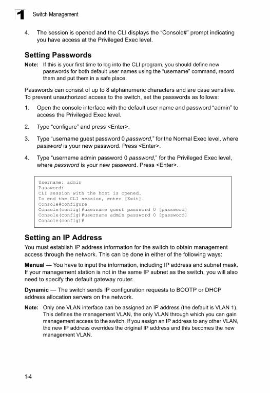
Passwords can consist of up to 8 alphanumeric characters and are case sensitive. To prevent unauthorized access to the switch, set the passwords as follows:
1. Open the console interface with the default user name and password “admin” to access the Privileged Exec level.
2. Type “configure” and press <Enter>.
3. Type “username guest password 0 password,” for the Normal Exec level, where password is your new password. Press <Enter>.
4. Type “username admin password 0 password,” for the Privileged Exec level, where password is your new password. Press <Enter>.
Setting an IP AddressYou must establish IP address information for the switch to obtain management access through the network. This can be done in either of the following ways:
Manual — You have to input the information, including IP address and subnet mask. If your management station is not in the same IP subnet as the switch, you will also need to specify the default gateway router.
Dynamic — The switch sends IP configuration requests to BOOTP or DHCP address allocation servers on the network.
Note: Only one VLAN interface can be assigned an IP address (the default is VLAN 1). This defines the management VLAN, the only VLAN through which you can gain management access to the switch. If you assign an IP address to any other VLAN, the new IP address overrides the original IP address and this becomes the new management VLAN.
Username: adminPassword:CLI session with the host is opened.To end the CLI session, enter [Exit].Console#configureConsole(config)#username guest password 0 [password]Console(config)#username admin password 0 [password]Console(config)#
Basic Configuration
1-5
1Manual ConfigurationYou can manually assign an IP address to the switch. You may also need to specify a default gateway that resides between this device and management stations that exist on another network segment.
Valid IP addresses consist of four decimal numbers, 0 to 255, separated by periods. Anything outside this format will not be accepted by the CLI program.
Note: The IP address for this switch is assigned via DHCP by default.
Before you can assign an IP address to the switch, you must obtain the following information from your network administrator:
• IP address for the switch • Default gateway for the network • Network mask for this network To assign an IP address to the switch, complete the following steps:
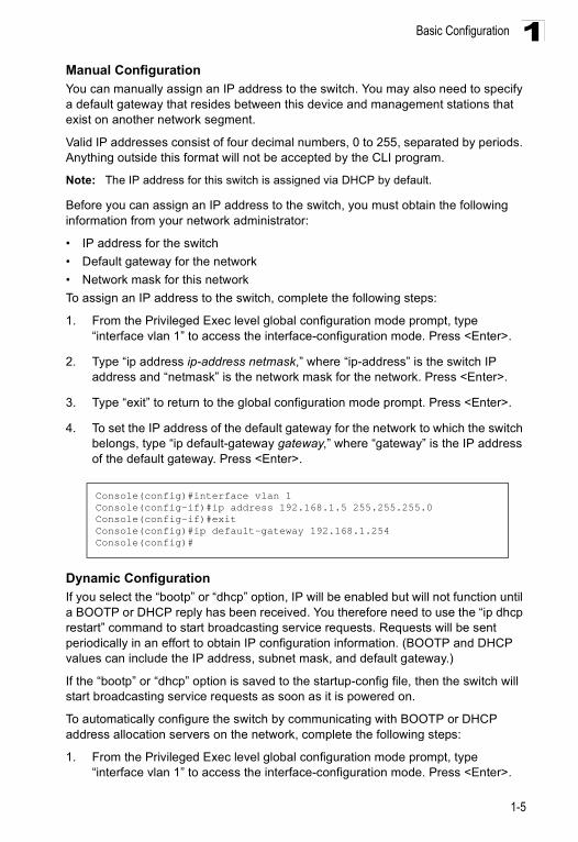
1. From the Privileged Exec level global configuration mode prompt, type “interface vlan 1” to access the interface-configuration mode. Press <Enter>.
2. Type “ip address ip-address netmask,” where “ip-address” is the switch IP address and “netmask” is the network mask for the network. Press <Enter>.
3. Type “exit” to return to the global configuration mode prompt. Press <Enter>.
4. To set the IP address of the default gateway for the network to which the switch belongs, type “ip default-gateway gateway,” where “gateway” is the IP address of the default gateway. Press <Enter>.
Dynamic ConfigurationIf you select the “bootp” or “dhcp” option, IP will be enabled but will not function until a BOOTP or DHCP reply has been received. You therefore need to use the “ip dhcp restart” command to start broadcasting service requests. Requests will be sent periodically in an effort to obtain IP configuration information. (BOOTP and DHCP values can include the IP address, subnet mask, and default gateway.)
If the “bootp” or “dhcp” option is saved to the startup-config file, then the switch will start broadcasting service requests as soon as it is powered on.
To automatically configure the switch by communicating with BOOTP or DHCP address allocation servers on the network, complete the following steps:
1. From the Privileged Exec level global configuration mode prompt, type “interface vlan 1” to access the interface-configuration mode. Press <Enter>.
Console(config)#interface vlan 1Console(config-if)#ip address 192.168.1.5 255.255.255.0Console(config-if)#exitConsole(config)#ip default-gateway 192.168.1.254Console(config)#
Switch Management
1-6
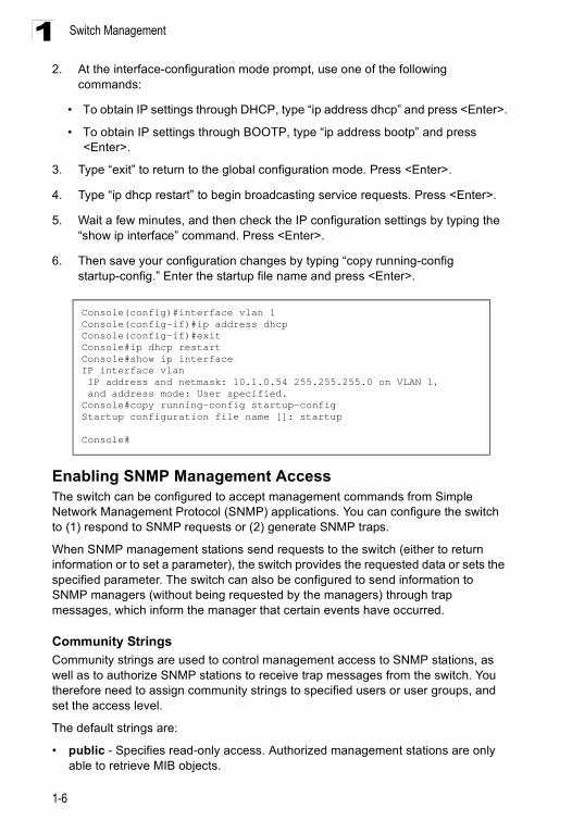
12. At the interface-configuration mode prompt, use one of the following
commands:
• To obtain IP settings through DHCP, type “ip address dhcp” and press <Enter>.
• To obtain IP settings through BOOTP, type “ip address bootp” and press <Enter>.
3. Type “exit” to return to the global configuration mode. Press <Enter>.
4. Type “ip dhcp restart” to begin broadcasting service requests. Press <Enter>.
5. Wait a few minutes, and then check the IP configuration settings by typing the “show ip interface” command. Press <Enter>.
6. Then save your configuration changes by typing “copy running-config startup-config.” Enter the startup file name and press <Enter>.
Enabling SNMP Management Access The switch can be configured to accept management commands from Simple Network Management Protocol (SNMP) applications. You can configure the switch to (1) respond to SNMP requests or (2) generate SNMP traps.
When SNMP management stations send requests to the switch (either to return information or to set a parameter), the switch provides the requested data or sets the specified parameter. The switch can also be configured to send information to SNMP managers (without being requested by the managers) through trap messages, which inform the manager that certain events have occurred.
Community StringsCommunity strings are used to control management access to SNMP stations, as well as to authorize SNMP stations to receive trap messages from the switch. You therefore need to assign community strings to specified users or user groups, and set the access level.
The default strings are:
• public - Specifies read-only access. Authorized management stations are only able to retrieve MIB objects.
Console(config)#interface vlan 1Console(config-if)#ip address dhcpConsole(config-if)#exitConsole#ip dhcp restartConsole#show ip interfaceIP interface vlan IP address and netmask: 10.1.0.54 255.255.255.0 on VLAN 1, and address mode: User specified.Console#copy running-config startup-configStartup configuration file name []: startup
Console#
Basic Configuration
1-7
1• private - Specifies read-write access. Authorized management stations are able
to both retrieve and modify MIB objects. Note: If you do not intend to utilize SNMP, it is recommended that you delete both of the
default community strings. If there are no community strings, then SNMP management access to the switch is disabled.
To prevent unauthorized access to the switch via SNMP, it is recommended that you change the default community strings.
To configure a community string, complete the following steps:
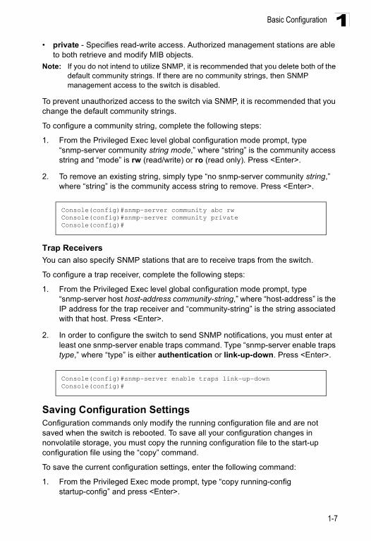
1. From the Privileged Exec level global configuration mode prompt, type “snmp-server community string mode,” where “string” is the community access string and “mode” is rw (read/write) or ro (read only). Press <Enter>.
2. To remove an existing string, simply type “no snmp-server community string,” where “string” is the community access string to remove. Press <Enter>.
Trap ReceiversYou can also specify SNMP stations that are to receive traps from the switch.
To configure a trap receiver, complete the following steps:
1. From the Privileged Exec level global configuration mode prompt, type “snmp-server host host-address community-string,” where “host-address” is the IP address for the trap receiver and “community-string” is the string associated with that host. Press <Enter>.
2. In order to configure the switch to send SNMP notifications, you must enter at least one snmp-server enable traps command. Type “snmp-server enable traps type,” where “type” is either authentication or link-up-down. Press <Enter>.
Saving Configuration SettingsConfiguration commands only modify the running configuration file and are not saved when the switch is rebooted. To save all your configuration changes in nonvolatile storage, you must copy the running configuration file to the start-up configuration file using the “copy” command.
To save the current configuration settings, enter the following command:
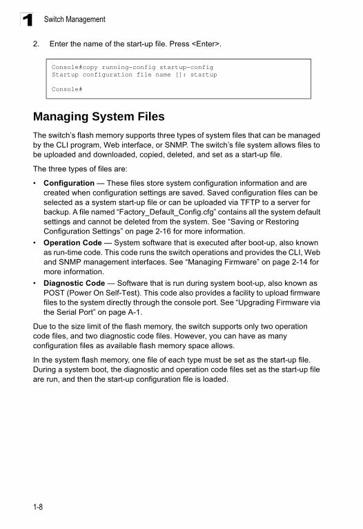
1. From the Privileged Exec mode prompt, type “copy running-config startup-config” and press <Enter>.
Console(config)#snmp-server community abc rwConsole(config)#snmp-server community privateConsole(config)#
Console(config)#snmp-server enable traps link-up-downConsole(config)#
Switch Management
1-8
12. Enter the name of the start-up file. Press <Enter>.
Managing System FilesThe switch’s flash memory supports three types of system files that can be managed by the CLI program, Web interface, or SNMP. The switch’s file system allows files to be uploaded and downloaded, copied, deleted, and set as a start-up file.
The three types of files are:
• Configuration — These files store system configuration information and are created when configuration settings are saved. Saved configuration files can be selected as a system start-up file or can be uploaded via TFTP to a server for backup. A file named “Factory_Default_Config.cfg” contains all the system default settings and cannot be deleted from the system. See “Saving or Restoring Configuration Settings” on page 2-16 for more information.
• Operation Code — System software that is executed after boot-up, also known as run-time code. This code runs the switch operations and provides the CLI, Web and SNMP management interfaces. See “Managing Firmware” on page 2-14 for more information.
• Diagnostic Code — Software that is run during system boot-up, also known as POST (Power On Self-Test). This code also provides a facility to upload firmware files to the system directly through the console port. See “Upgrading Firmware via the Serial Port” on page A-1.
Due to the size limit of the flash memory, the switch supports only two operation code files, and two diagnostic code files. However, you can have as many configuration files as available flash memory space allows.
In the system flash memory, one file of each type must be set as the start-up file. During a system boot, the diagnostic and operation code files set as the start-up file are run, and then the start-up configuration file is loaded.
Console#copy running-config startup-configStartup configuration file name []: startup
Console#
System Defaults
1-9
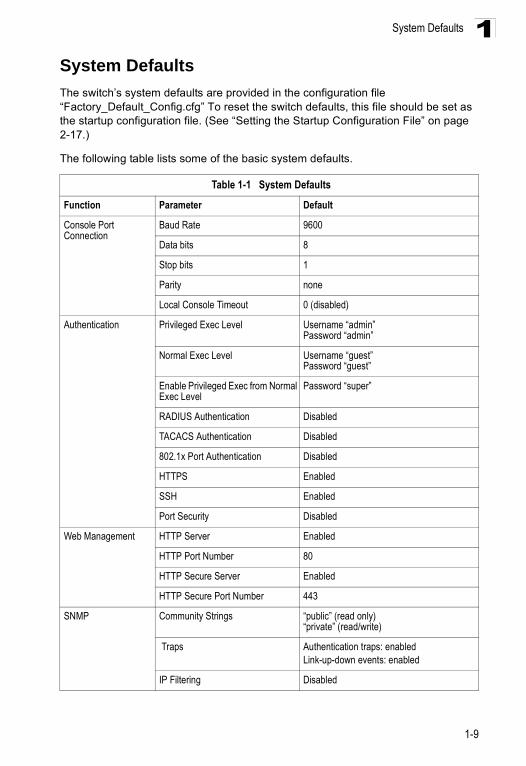
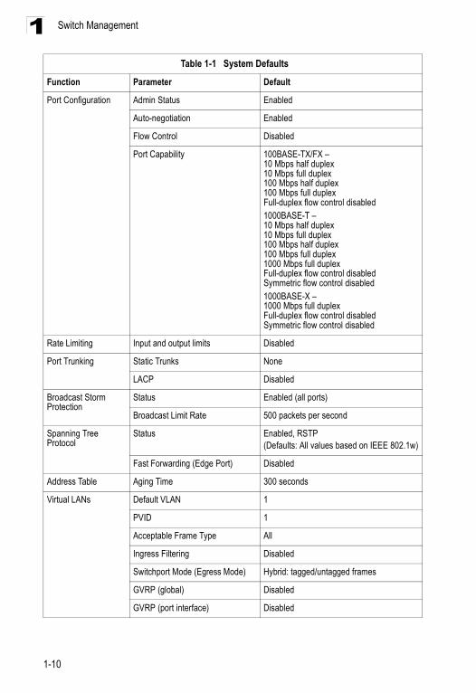
1System DefaultsThe switch’s system defaults are provided in the configuration file “Factory_Default_Config.cfg” To reset the switch defaults, this file should be set as the startup configuration file. (See “Setting the Startup Configuration File” on page 2-17.)
The following table lists some of the basic system defaults.
Table 1-1 System Defaults
Function Parameter Default
Console Port Connection
Baud Rate 9600
Data bits 8
Stop bits 1
Parity none
Local Console Timeout 0 (disabled)
Authentication Privileged Exec Level Username “admin”Password “admin”
Normal Exec Level Username “guest”Password “guest”
Enable Privileged Exec from Normal Exec Level
Password “super”
RADIUS Authentication Disabled
TACACS Authentication Disabled
802.1x Port Authentication Disabled
HTTPS Enabled
SSH Enabled
Port Security Disabled
Web Management HTTP Server Enabled
HTTP Port Number 80
HTTP Secure Server Enabled
HTTP Secure Port Number 443
SNMP Community Strings “public” (read only) “private” (read/write)
Traps Authentication traps: enabledLink-up-down events: enabled
IP Filtering Disabled
Switch Management
1-10
1
Port Configuration Admin Status Enabled
Auto-negotiation Enabled
Flow Control Disabled
Port Capability 100BASE-TX/FX –10 Mbps half duplex10 Mbps full duplex100 Mbps half duplex100 Mbps full duplexFull-duplex flow control disabled1000BASE-T –10 Mbps half duplex10 Mbps full duplex100 Mbps half duplex100 Mbps full duplex1000 Mbps full duplexFull-duplex flow control disabledSymmetric flow control disabled1000BASE-X –1000 Mbps full duplexFull-duplex flow control disabledSymmetric flow control disabled
Rate Limiting Input and output limits Disabled
Port Trunking Static Trunks None
LACP Disabled
Broadcast Storm Protection
Status Enabled (all ports)
Broadcast Limit Rate 500 packets per second
Spanning Tree Protocol
Status Enabled, RSTP(Defaults: All values based on IEEE 802.1w)
Fast Forwarding (Edge Port) Disabled
Address Table Aging Time 300 seconds
Virtual LANs Default VLAN 1
PVID 1
Acceptable Frame Type All
Ingress Filtering Disabled
Switchport Mode (Egress Mode) Hybrid: tagged/untagged frames
GVRP (global) Disabled
GVRP (port interface) Disabled
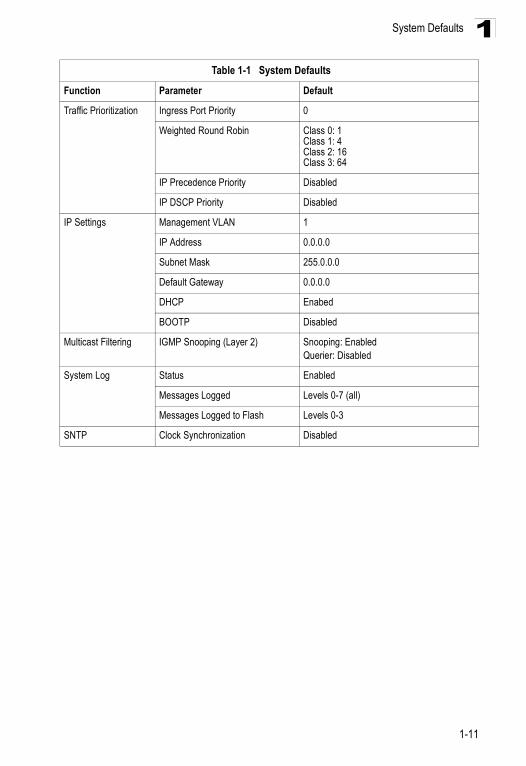
Table 1-1 System Defaults
Function Parameter Default
System Defaults
1-11
1
Traffic Prioritization Ingress Port Priority 0
Weighted Round Robin Class 0: 1Class 1: 4Class 2: 16Class 3: 64
IP Precedence Priority Disabled
IP DSCP Priority Disabled
IP Settings Management VLAN 1
IP Address 0.0.0.0
Subnet Mask 255.0.0.0
Default Gateway 0.0.0.0
DHCP Enabed
BOOTP Disabled
Multicast Filtering IGMP Snooping (Layer 2) Snooping: EnabledQuerier: Disabled
System Log Status Enabled
Messages Logged Levels 0-7 (all)
Messages Logged to Flash Levels 0-3
SNTP Clock Synchronization Disabled
Table 1-1 System Defaults
Function Parameter Default

Switch Management
1-12
1
2-1
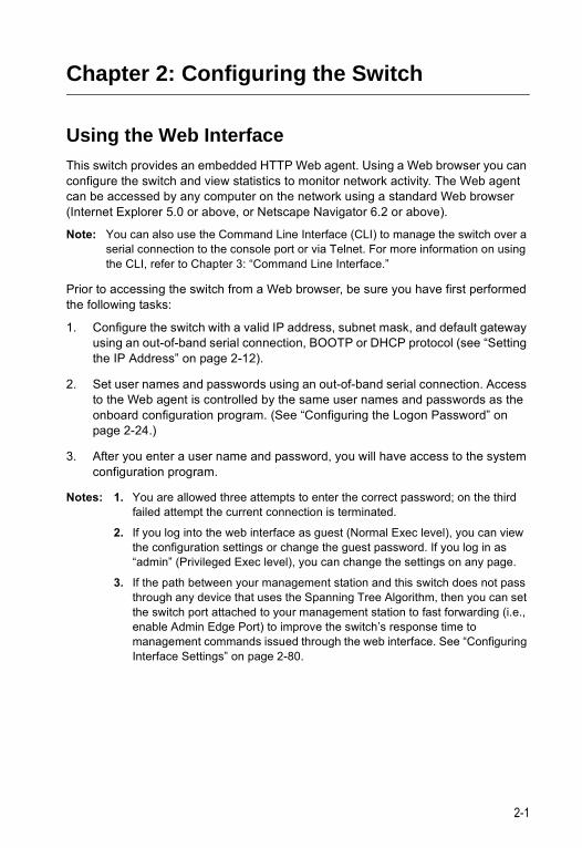
Chapter 2: Configuring the Switch
Using the Web InterfaceThis switch provides an embedded HTTP Web agent. Using a Web browser you can configure the switch and view statistics to monitor network activity. The Web agent can be accessed by any computer on the network using a standard Web browser (Internet Explorer 5.0 or above, or Netscape Navigator 6.2 or above).
Note: You can also use the Command Line Interface (CLI) to manage the switch over a serial connection to the console port or via Telnet. For more information on using the CLI, refer to Chapter 3: “Command Line Interface.”
Prior to accessing the switch from a Web browser, be sure you have first performed the following tasks:
1. Configure the switch with a valid IP address, subnet mask, and default gateway using an out-of-band serial connection, BOOTP or DHCP protocol (see “Setting the IP Address” on page 2-12).
2. Set user names and passwords using an out-of-band serial connection. Access to the Web agent is controlled by the same user names and passwords as the onboard configuration program. (See “Configuring the Logon Password” on page 2-24.)
3. After you enter a user name and password, you will have access to the system configuration program.
Notes: 1. You are allowed three attempts to enter the correct password; on the third failed attempt the current connection is terminated.
2. If you log into the web interface as guest (Normal Exec level), you can view the configuration settings or change the guest password. If you log in as “admin” (Privileged Exec level), you can change the settings on any page.
3. If the path between your management station and this switch does not pass through any device that uses the Spanning Tree Algorithm, then you can set the switch port attached to your management station to fast forwarding (i.e., enable Admin Edge Port) to improve the switch’s response time to management commands issued through the web interface. See “Configuring Interface Settings” on page 2-80.
Configuring the Switch
2-2
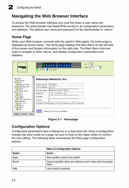
2Navigating the Web Browser InterfaceTo access the Web-browser interface you must first enter a user name and password. The administrator has Read/Write access to all configuration parameters and statistics. The default user name and password for the administrator is “admin.”
Home PageWhen your Web browser connects with the switch’s Web agent, the home page is displayed as shown below. The home page displays the Main Menu on the left side of the screen and System Information on the right side. The Main Menu links are used to navigate to other menus, and display configuration parameters and statistics.
Figure 2-1 Homepage
Configuration OptionsConfigurable parameters have a dialog box or a drop-down list. Once a configuration change has been made on a page, be sure to click on the Apply button to confirm the new setting. The following table summarizes the Web page configuration buttons.
Table 2-2 Configuration OptionsButton ActionApply Sets specified values to the system. Revert Cancels specified values and restores current values prior to pressing
Apply.Help Links directly to webhelp.
Panel Display
2-3
2Notes: 1. To ensure proper screen refresh, be sure that Internet Explorer 5.x is
configured as follows: Under the menu “Tools / Internet Options / General / Temporary Internet Files / Settings,” the setting for item “Check for newer versions of stored pages” should be “Every visit to the page.”
2. When using Internet Explorer 5.0, you may have to manually refresh the screen after making configuration changes by pressing the browser’s refresh button.
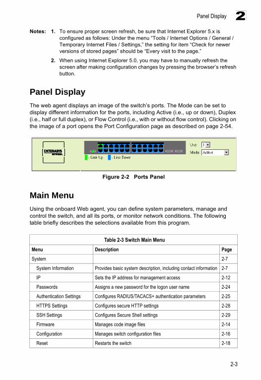
Panel DisplayThe web agent displays an image of the switch’s ports. The Mode can be set to display different information for the ports, including Active (i.e., up or down), Duplex (i.e., half or full duplex), or Flow Control (i.e., with or without flow control). Clicking on the image of a port opens the Port Configuration page as described on page 2-54.
Figure 2-2 Ports Panel
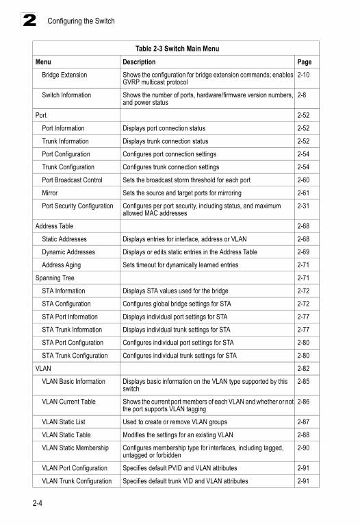
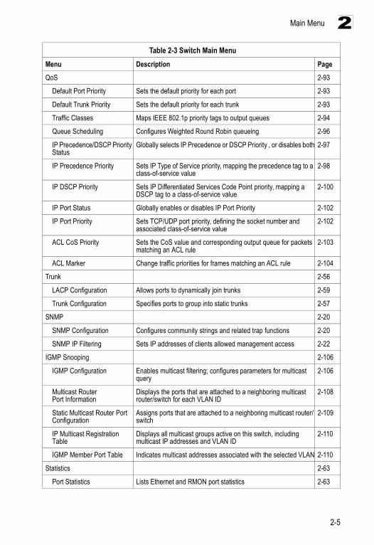
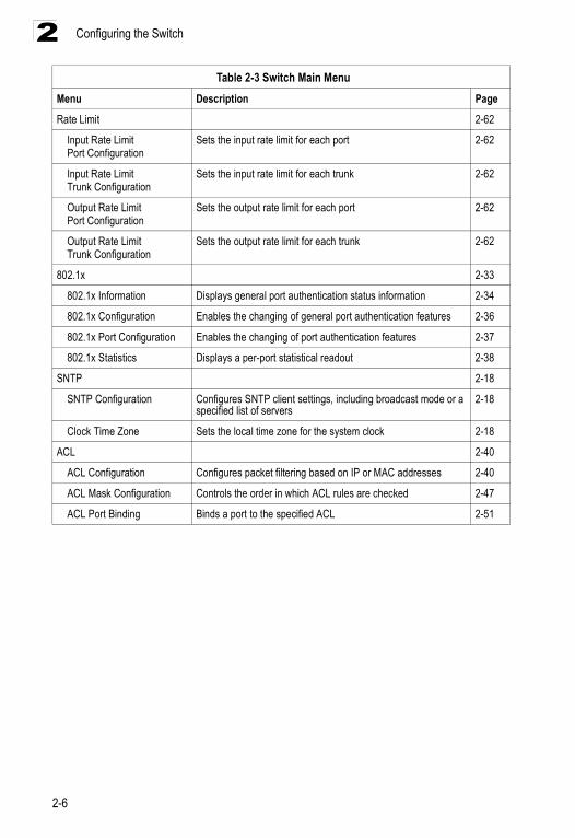
Main MenuUsing the onboard Web agent, you can define system parameters, manage and control the switch, and all its ports, or monitor network conditions. The following table briefly describes the selections available from this program.
Table 2-3 Switch Main MenuMenu Description Page
System 2-7
System Information Provides basic system description, including contact information 2-7
IP Sets the IP address for management access 2-12
Passwords Assigns a new password for the logon user name 2-24
Authentication Settings Configures RADIUS/TACACS+ authentication parameters 2-25
HTTPS Settings Configures secure HTTP settings 2-28
SSH Settings Configures Secure Shell settings 2-29
Firmware Manages code image files 2-14
Configuration Manages switch configuration files 2-16
Reset Restarts the switch 2-18
Configuring the Switch
2-4
2
Bridge Extension Shows the configuration for bridge extension commands; enables GVRP multicast protocol
2-10
Switch Information Shows the number of ports, hardware/firmware version numbers, and power status
2-8
Port 2-52
Port Information Displays port connection status 2-52
Trunk Information Displays trunk connection status 2-52
Port Configuration Configures port connection settings 2-54
Trunk Configuration Configures trunk connection settings 2-54
Port Broadcast Control Sets the broadcast storm threshold for each port 2-60
Mirror Sets the source and target ports for mirroring 2-61
Port Security Configuration Configures per port security, including status, and maximum allowed MAC addresses
2-31
Address Table 2-68
Static Addresses Displays entries for interface, address or VLAN 2-68
Dynamic Addresses Displays or edits static entries in the Address Table 2-69
Address Aging Sets timeout for dynamically learned entries 2-71
Spanning Tree 2-71
STA Information Displays STA values used for the bridge 2-72
STA Configuration Configures global bridge settings for STA 2-72
STA Port Information Displays individual port settings for STA 2-77
STA Trunk Information Displays individual trunk settings for STA 2-77
STA Port Configuration Configures individual port settings for STA 2-80
STA Trunk Configuration Configures individual trunk settings for STA 2-80
VLAN 2-82
VLAN Basic Information Displays basic information on the VLAN type supported by this switch
2-85
VLAN Current Table Shows the current port members of each VLAN and whether or not the port supports VLAN tagging
2-86
VLAN Static List Used to create or remove VLAN groups 2-87
VLAN Static Table Modifies the settings for an existing VLAN 2-88
VLAN Static Membership Configures membership type for interfaces, including tagged, untagged or forbidden
2-90
VLAN Port Configuration Specifies default PVID and VLAN attributes 2-91
VLAN Trunk Configuration Specifies default trunk VID and VLAN attributes 2-91
Table 2-3 Switch Main MenuMenu Description Page
Main Menu
2-5
2
QoS 2-93
Default Port Priority Sets the default priority for each port 2-93
Default Trunk Priority Sets the default priority for each trunk 2-93
Traffic Classes Maps IEEE 802.1p priority tags to output queues 2-94
Queue Scheduling Configures Weighted Round Robin queueing 2-96
IP Precedence/DSCP Priority Status
Globally selects IP Precedence or DSCP Priority , or disables both 2-97
IP Precedence Priority Sets IP Type of Service priority, mapping the precedence tag to a class-of-service value
2-98
IP DSCP Priority Sets IP Differentiated Services Code Point priority, mapping a DSCP tag to a class-of-service value
2-100
IP Port Status Globally enables or disables IP Port Priority 2-102
IP Port Priority Sets TCP/UDP port priority, defining the socket number and associated class-of-service value
2-102
ACL CoS Priority Sets the CoS value and corresponding output queue for packets matching an ACL rule
2-103
ACL Marker Change traffic priorities for frames matching an ACL rule 2-104
Trunk 2-56
LACP Configuration Allows ports to dynamically join trunks 2-59
Trunk Configuration Specifies ports to group into static trunks 2-57
SNMP 2-20
SNMP Configuration Configures community strings and related trap functions 2-20
SNMP IP Filtering Sets IP addresses of clients allowed management access 2-22
IGMP Snooping 2-106
IGMP Configuration Enables multicast filtering; configures parameters for multicast query
2-106
Multicast Router Port Information
Displays the ports that are attached to a neighboring multicast router/switch for each VLAN ID
2-108
Static Multicast Router Port Configuration
Assigns ports that are attached to a neighboring multicast router/switch
2-109
IP Multicast Registration Table
Displays all multicast groups active on this switch, including multicast IP addresses and VLAN ID
2-110
IGMP Member Port Table Indicates multicast addresses associated with the selected VLAN 2-110
Statistics 2-63
Port Statistics Lists Ethernet and RMON port statistics 2-63
Table 2-3 Switch Main MenuMenu Description Page
Configuring the Switch
2-6
2
Rate Limit 2-62
Input Rate Limit Port Configuration
Sets the input rate limit for each port 2-62
Input Rate Limit Trunk Configuration
Sets the input rate limit for each trunk 2-62
Output Rate Limit Port Configuration
Sets the output rate limit for each port 2-62
Output Rate Limit Trunk Configuration
Sets the output rate limit for each trunk 2-62
802.1x 2-33
802.1x Information Displays general port authentication status information 2-34
802.1x Configuration Enables the changing of general port authentication features 2-36
802.1x Port Configuration Enables the changing of port authentication features 2-37
802.1x Statistics Displays a per-port statistical readout 2-38
SNTP 2-18
SNTP Configuration Configures SNTP client settings, including broadcast mode or a specified list of servers
2-18
Clock Time Zone Sets the local time zone for the system clock 2-18
ACL 2-40
ACL Configuration Configures packet filtering based on IP or MAC addresses 2-40
ACL Mask Configuration Controls the order in which ACL rules are checked 2-47
ACL Port Binding Binds a port to the specified ACL 2-51
Table 2-3 Switch Main MenuMenu Description Page
Basic Configuration
2-7
2Basic Configuration
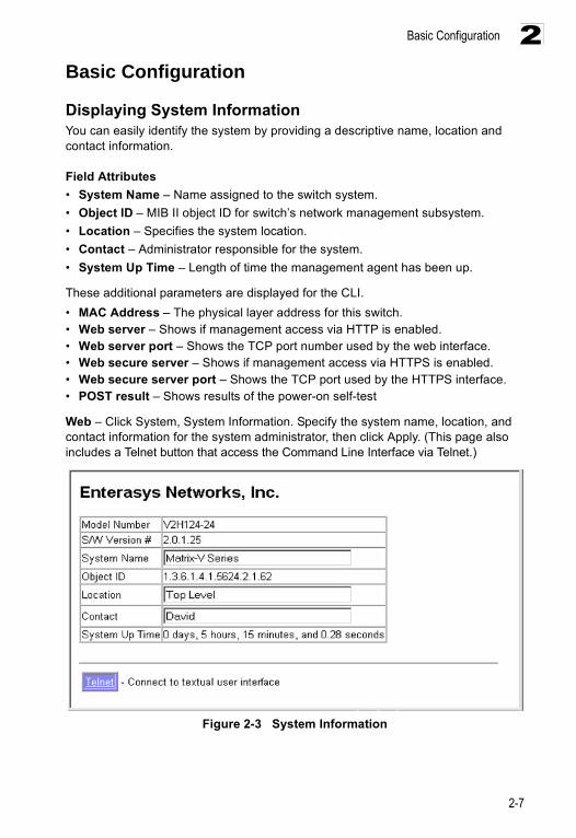
Displaying System InformationYou can easily identify the system by providing a descriptive name, location and contact information.
Field Attributes• System Name – Name assigned to the switch system.• Object ID – MIB II object ID for switch’s network management subsystem.• Location – Specifies the system location. • Contact – Administrator responsible for the system.• System Up Time – Length of time the management agent has been up.
These additional parameters are displayed for the CLI.• MAC Address – The physical layer address for this switch. • Web server – Shows if management access via HTTP is enabled.• Web server port – Shows the TCP port number used by the web interface.• Web secure server – Shows if management access via HTTPS is enabled.• Web secure server port – Shows the TCP port used by the HTTPS interface.• POST result – Shows results of the power-on self-test
Web – Click System, System Information. Specify the system name, location, and contact information for the system administrator, then click Apply. (This page also includes a Telnet button that access the Command Line Interface via Telnet.)
Figure 2-3 System Information
Configuring the Switch
2-8
2CLI – Specify the hostname, location and contact information.
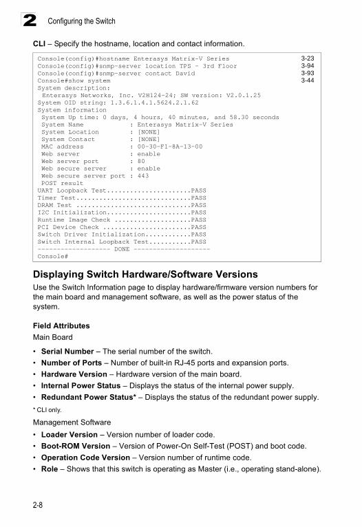
Displaying Switch Hardware/Software Versions Use the Switch Information page to display hardware/firmware version numbers for the main board and management software, as well as the power status of the system.
Field AttributesMain Board
• Serial Number – The serial number of the switch.• Number of Ports – Number of built-in RJ-45 ports and expansion ports.• Hardware Version – Hardware version of the main board.• Internal Power Status – Displays the status of the internal power supply.• Redundant Power Status* – Displays the status of the redundant power supply.* CLI only.
Management Software• Loader Version – Version number of loader code.• Boot-ROM Version – Version of Power-On Self-Test (POST) and boot code.• Operation Code Version – Version number of runtime code.• Role – Shows that this switch is operating as Master (i.e., operating stand-alone).
Console(config)#hostname Enterasys Matrix-V Series 3-23Console(config)#snmp-server location TPS - 3rd Floor 3-94Console(config)#snmp-server contact David 3-93Console#show system 3-44System description: Enterasys Networks, Inc. V2H124-24; SW version: V2.0.1.25
System OID string: 1.3.6.1.4.1.5624.2.1.62System information System Up time: 0 days, 4 hours, 40 minutes, and 58.30 seconds System Name : Enterasys Matrix-V Series System Location : [NONE] System Contact : [NONE] MAC address : 00-30-F1-8A-13-00 Web server : enable Web server port : 80 Web secure server : enable Web secure server port : 443 POST resultUART Loopback Test......................PASSTimer Test..............................PASSDRAM Test ..............................PASSI2C Initialization......................PASSRuntime Image Check ....................PASSPCI Device Check .......................PASSSwitch Driver Initialization............PASSSwitch Internal Loopback Test...........PASS------------------- DONE --------------------Console#
Basic Configuration
2-9
2Expansion Slot• Expansion Slot 1/2 – Slots for extender modules.
Web – Click System, Switch Information.
Figure 2-4 General Switch Information
CLI – Use the following command to display version information.
Console#show version 3-45Unit1 Serial number :A224029499 Service tag : Hardware version :R0A Module A type :not present Module B type :not present Number of ports :24 Main power status :up Redundant power status :not presentAgent(master) Unit id :1 Loader version :0.0.6.5 Boot rom version :1.0.1.4 Operation code version :0.1.2.1Console#
Configuring the Switch
2-10
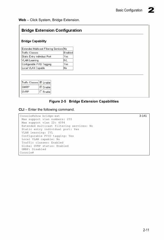
2Displaying Bridge Extension CapabilitiesThe Bridge MIB includes extensions for managed devices that support Multicast Filtering, Traffic Classes, and Virtual LANs. You can access these extensions to display default settings for the key variables, or to configure the global setting for GARP VLAN Registration Protocol (GVRP).
Field Attributes• Extended Multicast Filtering Services – This switch does not support the filtering
of individual multicast addresses based on GMRP (GARP Multicast Registration Protocol).
• Traffic Classes – This switch provides mapping of user priorities to multiple traffic classes. (Refer to “Class of Service Configuration” on page 2-93.)
• Static Entry Individual Port – This switch allows static filtering for unicast and multicast addresses. (Refer to “Setting Static Addresses” on page 2-68.)
• VLAN Learning – This switch uses Independent VLAN Learning (IVL), where each port maintains its own filtering database.
• Configurable PVID Tagging – This switch allows you to override the default Port VLAN ID (PVID used in frame tags) and egress status (VLAN-Tagged or Untagged) on each port. (Refer to “VLAN Configuration” on page 2-82.)
• Local VLAN Capable – This switch does not support multiple local bridges (i.e., multiple Spanning Trees).
• GMRP – GARP Multicast Registration Protocol (GMRP) allows network devices to register endstations with multicast groups. This switch does not support GMRP; it uses the Internet Group Management Protocol (IGMP) to provide automatic multicast filtering.
• GVRP – GARP VLAN Registration Protocol (GVRP) defines a way for switches to exchange VLAN information in order to register necessary VLAN members on ports across the network. This function should be enabled to permit VLAN groups which extend beyond the local switch. (Default: Disabled)
Basic Configuration
2-11
2Web – Click System, Bridge Extension.
Figure 2-5 Bridge Extension Capabilities
CLI – Enter the following command.
Console#show bridge-ext 3-141 Max support vlan numbers: 255 Max support vlan ID: 4094 Extended multicast filtering services: No Static entry individual port: Yes VLAN learning: IVL Configurable PVID tagging: Yes Local VLAN capable: No Traffic classes: Enabled Global GVRP status: Enabled GMRP: DisabledConsole#
Configuring the Switch
2-12
2Setting the IP Address An IP address may be used for management access to the switch over your network. By default, the switch uses DHCP to assign IP settings to VLAN 1 on the switch. If you wish to manually configure IP settings, you need to change the switch’s user-specified defaults (IP address 0.0.0.0 and netmask 255.0.0.0) to values that are compatible with your network. You may also need to establish a default gateway between the switch and management stations that exist on another network segment.
You can manually configure a specific IP address, or direct the device to obtain an address from a BOOTP or DHCP server when it is powered on. Valid IP addresses consist of four decimal numbers, 0 to 255, separated by periods. Anything outside this format will not be accepted by the CLI program.
Command Attributes• Management VLAN – This is the only VLAN through which you can gain
management access to the switch. By default, all ports on the switch are members of VLAN 1, so a management station can be connected to any port on the switch. However, if other VLANs are configured and you change the Management VLAN, you may lose management access to the switch. In this case, you should reconnect the management station to a port that is a member of the Management VLAN.
• IP Address Mode – Specifies whether IP functionality is enabled via manual configuration (Static), Dynamic Host Configuration Protocol (DHCP), or Boot Protocol (BOOTP). If DHCP/BOOTP is enabled, IP will not function until a reply has been received from the server. Requests will be broadcast periodically by the switch for an IP address. (DHCP/BOOTP values can include the IP address, subnet mask, and default gateway.)
• IP Address – Address of the VLAN interface that is allowed management access. Valid IP addresses consist of four numbers, 0 to 255, separated by periods.
• Subnet Mask – This mask identifies the host address bits used for routing to specific subnets.
• Gateway IP Address – IP address of the gateway router between this device and management stations that exist on other network segments.
• MAC Address – The MAC address of this switch.
Basic Configuration
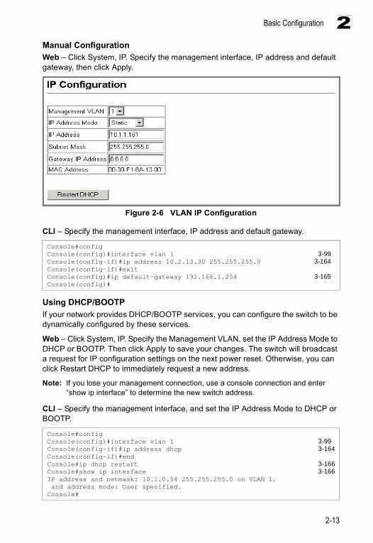
2-13
2Manual ConfigurationWeb – Click System, IP. Specify the management interface, IP address and default gateway, then click Apply.
Figure 2-6 VLAN IP Configuration
CLI – Specify the management interface, IP address and default gateway.
Using DHCP/BOOTP If your network provides DHCP/BOOTP services, you can configure the switch to be dynamically configured by these services.
Web – Click System, IP. Specify the Management VLAN, set the IP Address Mode to DHCP or BOOTP. Then click Apply to save your changes. The switch will broadcast a request for IP configuration settings on the next power reset. Otherwise, you can click Restart DHCP to immediately request a new address.
Note: If you lose your management connection, use a console connection and enter “show ip interface” to determine the new switch address.
CLI – Specify the management interface, and set the IP Address Mode to DHCP or BOOTP.
Console#configConsole(config)#interface vlan 1 3-99Console(config-if)#ip address 10.2.13.30 255.255.255.0 3-164Console(config-if)#exitConsole(config)#ip default-gateway 192.168.1.254 3-165Console(config)#
Console#configConsole(config)#interface vlan 1 3-99Console(config-if)#ip address dhcp 3-164Console(config-if)#endConsole#ip dhcp restart 3-166Console#show ip interface 3-166IP address and netmask: 10.1.0.54 255.255.255.0 on VLAN 1, and address mode: User specified.Console#
Configuring the Switch
2-14
2Renewing DCHP – DHCP may lease addresses to clients indefinitely or for a specific period of time. If the address expires or the switch is moved to another network segment, you will lose management access to the switch. In this case, you can reboot the switch or submit a client request to restart DHCP service.
Web – If the address assigned by DHCP is no longer functioning, you will not be able to renew the IP settings via the Web interface. You can only restart DHCP service via the Web interface if the current address is still available.
CLI – Enter the following command to restart DHCP service.
Managing FirmwareYou can upload/download firmware to or from a TFTP server. By saving runtime code to a file on a TFTP server, that file can later be downloaded to the switch to restore operation. You can also set the switch to use new firmware without overwriting the previous version.
Command Attributes• TFTP Server IP Address – The IP address of a TFTP server.• Destination File Name – The file name should not contain slashes (\ or /), the
leading letter of the file name should not be a period (.), and the maximum length for file names on the TFTP server is 127 characters or 31 characters for files on the switch. (Valid characters: A-Z, a-z, 0-9, “.”, “-”, “_”)
Note: Up to two copies of the system software (i.e., the runtime firmware) can be stored in the file directory on the switch. The currently designated startup version of this file cannot be deleted.
Downloading System Software from a ServerWhen downloading runtime code, you can specify the Destination File Name to replace the current image, or first download the file using a different name from the current runtime code file, and then set the new file as the startup file.
Console#ip dhcp restart 3-166Console#
Basic Configuration
2-15
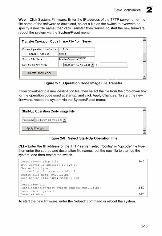
2Web – Click System, Firmware. Enter the IP address of the TFTP server, enter the file name of the software to download, select a file on the switch to overwrite or specify a new file name, then click Transfer from Server. To start the new firmware, reboot the system via the System/Reset menu.
Figure 2-7 Operation Code Image File Transfer
If you download to a new destination file, then select the file from the drop-down box for the operation code used at startup, and click Apply Changes. To start the new firmware, reboot the system via the System/Reset menu.
Figure 2-8 Select Start-Up Operation File
CLI – Enter the IP address of the TFTP server, select “config” or “opcode” file type, then enter the source and destination file names, set the new file to start up the system, and then restart the switch.
To start the new firmware, enter the “reload” command or reboot the system.
Console#copy tftp file 3-46TFTP server ip address: 10.1.0.99Choose file type: 1. config: 2. opcode: <1-2>: 2Source file name: MCD0121.bixDestination file name: mcd0121.bix/Console#configConsole(config)#boot system opcode: mcd0121.bix 3-50Console(config)#exitConsole#reload 3-20
Configuring the Switch
2-16
2Saving or Restoring Configuration SettingsYou can upload/download configuration settings to/from a TFTP server. The configuration file can be later downloaded to restore the switch’s settings.
Command Attributes• TFTP Server IP Address — The IP address of a TFTP server.• Destination File Name —The configuration file name should not contain slashes
(\ or /), the leading letter of the file name should not be a period (.), and the maximum length for file names on the TFTP server is 127 characters or 31 characters for files on the switch. (Valid characters: A-Z, a-z, 0-9, “.”, “-”, “_”)
Note: The maximum number of user-defined configuration files is limited only by available Flash memory space.
Downloading Configuration Settings from a ServerYou can save the configuration file under a new file name and then set it as the startup file, or you can specify the current startup configuration file as the destination file to directly replace it. Note that the file “Factory_Default_Config.cfg” can be copied to the TFTP server, but cannot be used as a destination on the switch.
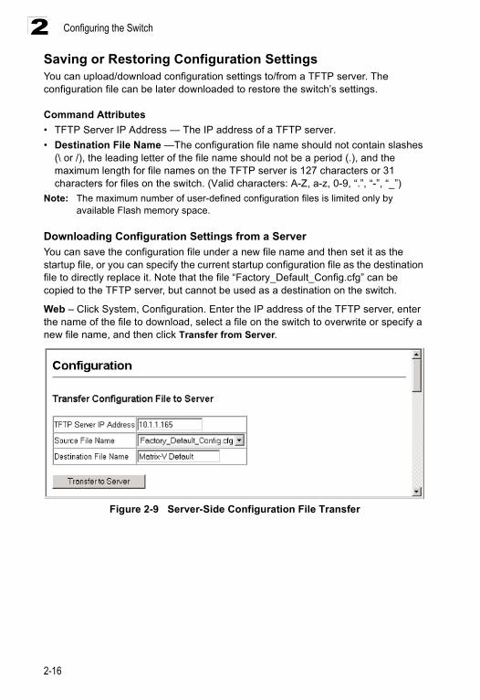
Web – Click System, Configuration. Enter the IP address of the TFTP server, enter the name of the file to download, select a file on the switch to overwrite or specify a new file name, and then click Transfer from Server.
Figure 2-9 Server-Side Configuration File Transfer
Basic Configuration
2-17
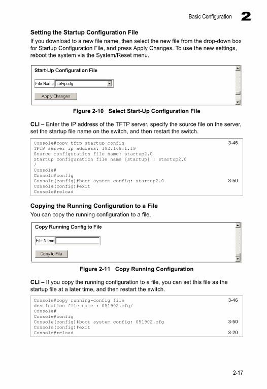
2Setting the Startup Configuration FileIf you download to a new file name, then select the new file from the drop-down box for Startup Configuration File, and press Apply Changes. To use the new settings, reboot the system via the System/Reset menu.
Figure 2-10 Select Start-Up Configuration File
CLI – Enter the IP address of the TFTP server, specify the source file on the server, set the startup file name on the switch, and then restart the switch.
Copying the Running Configuration to a FileYou can copy the running configuration to a file.
Figure 2-11 Copy Running Configuration
CLI – If you copy the running configuration to a file, you can set this file as the startup file at a later time, and then restart the switch.
Console#copy tftp startup-config 3-46TFTP server ip address: 192.168.1.19Source configuration file name: startup2.0Startup configuration file name [startup] : startup2.0/Console#Console#configConsole(config)#boot system config: startup2.0 3-50Console(config)#exitConsole#reload
Console#copy running-config file 3-46destination file name : 051902.cfg/Console#Console#configConsole(config)#boot system config: 051902.cfg 3-50Console(config)#exitConsole#reload 3-20
Configuring the Switch
2-18
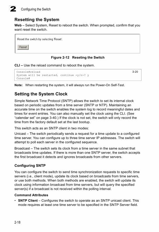
2Resetting the SystemWeb – Select System, Reset to reboot the switch. When prompted, confirm that you want reset the switch.
Figure 2-12 Reseting the Switch
CLI – Use the reload command to reboot the system.
Note: When restarting the system, it will always run the Power-On Self-Test.
Setting the System Clock Simple Network Time Protocol (SNTP) allows the switch to set its internal clock based on periodic updates from a time server (SNTP or NTP). Maintaining an accurate time on the switch enables the system log to record meaningful dates and times for event entries. You can also manually set the clock using the CLI. (See “calendar set” on page 3-40.) If the clock is not set, the switch will only record the time from the factory default set at the last bootup.
This switch acts as an SNTP client in two modes: Unicast – The switch periodically sends a request for a time update to a configured time server. You can configure up to three time server IP addresses. The switch will attempt to poll each server in the configured sequence.
Broadcast – The switch sets its clock from a time server in the same subnet that broadcasts time updates. If there is more than one SNTP server, the switch accepts the first broadcast it detects and ignores broadcasts from other servers.
Configuring SNTPYou can configure the switch to send time synchronization requests to specific time servers (i.e., client mode), update its clock based on broadcasts from time servers, or use both methods. When both methods are enabled, the switch will update its clock using information broadcast from time servers, but will query the specified server(s) if a broadcast is not received within the polling interval.
Command Attributes• SNTP Client – Configures the switch to operate as an SNTP unicast client. This
mode requires at least one time server to be specified in the SNTP Server field.
Console#reload 3-20System will be restarted, continue <y/n>? yConsole#
Basic Configuration
2-19
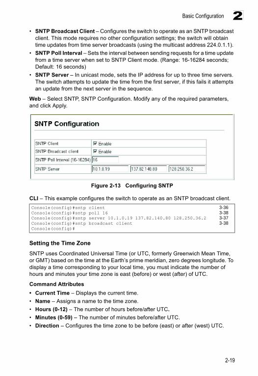
2• SNTP Broadcast Client – Configures the switch to operate as an SNTP broadcast
client. This mode requires no other configuration settings; the switch will obtain time updates from time server broadcasts (using the multicast address 224.0.1.1).
• SNTP Poll Interval – Sets the interval between sending requests for a time update from a time server when set to SNTP Client mode. (Range: 16-16284 seconds; Default: 16 seconds)
• SNTP Server – In unicast mode, sets the IP address for up to three time servers. The switch attempts to update the time from the first server, if this fails it attempts an update from the next server in the sequence.
Web – Select SNTP, SNTP Configuration. Modify any of the required parameters, and click Apply.
Figure 2-13 Configuring SNTP
CLI – This example configures the switch to operate as an SNTP broadcast client.
Setting the Time ZoneSNTP uses Coordinated Universal Time (or UTC, formerly Greenwich Mean Time, or GMT) based on the time at the Earth’s prime meridian, zero degrees longitude. To display a time corresponding to your local time, you must indicate the number of hours and minutes your time zone is east (before) or west (after) of UTC.
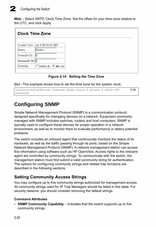
Command Attributes• Current Time – Displays the current time.• Name – Assigns a name to the time zone.• Hours (0-12) – The number of hours before/after UTC.• Minutes (0-59) – The number of minutes before/after UTC.• Direction – Configures the time zone to be before (east) or after (west) UTC.
Console(config)#sntp client 3-36Console(config)#sntp poll 16 3-38Console(config)#sntp server 10.1.0.19 137.82.140.80 128.250.36.2 3-37Console(config)#sntp broadcast client 3-38Console(config)#
Configuring the Switch
2-20
2Web – Select SNTP, Clock Time Zone. Set the offset for your time zone relative to the UTC, and click Apply.
Figure 2-14 Setting the Time Zone
CLI - This example shows how to set the time zone for the system clock.
Configuring SNMPSimple Network Management Protocol (SNMP) is a communication protocol designed specifically for managing devices on a network. Equipment commonly managed with SNMP includes switches, routers and host computers. SNMP is typically used to configure these devices for proper operation in a network environment, as well as to monitor them to evaluate performance or detect potential problems.
The switch includes an onboard agent that continuously monitors the status of its hardware, as well as the traffic passing through its ports, based on the Simple Network Management Protocol (SNMP). A network management station can access this information using software such as HP OpenView. Access rights to the onboard agent are controlled by community strings. To communicate with the switch, the management station must first submit a valid community string for authentication. The options for configuring community strings and related trap functions are described in the following sections.
Setting Community Access Strings You may configure up to five community strings authorized for management access. All community strings used for IP Trap Managers should be listed in this table. For security reasons, you should consider removing the default strings.
Command Attributes• SNMP Community Capability – Indicates that the switch supports up to five
community strings.
Console(config)#clock timezone Dhaka hours 6 minute 0 after-UTC 3-36Console#
Configuring SNMP
2-21
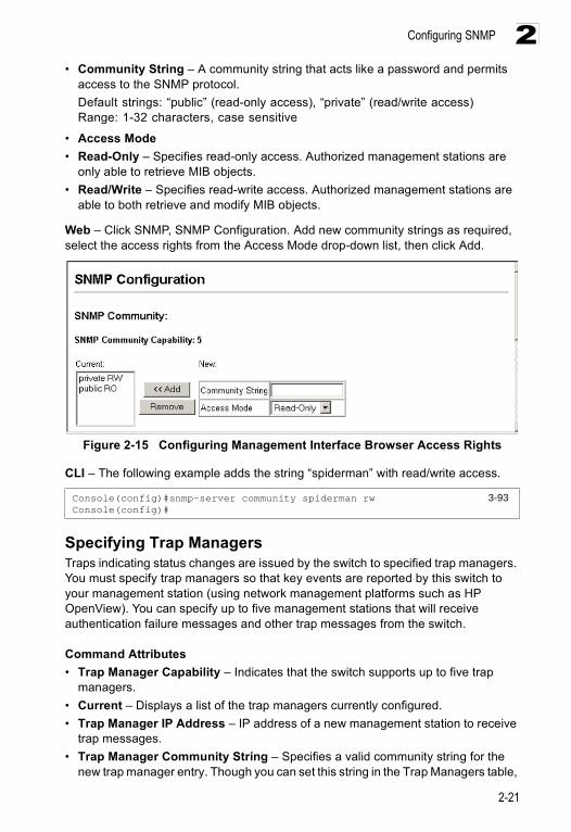
2• Community String – A community string that acts like a password and permits
access to the SNMP protocol. Default strings: “public” (read-only access), “private” (read/write access)Range: 1-32 characters, case sensitive
• Access Mode • Read-Only – Specifies read-only access. Authorized management stations are
only able to retrieve MIB objects. • Read/Write – Specifies read-write access. Authorized management stations are
able to both retrieve and modify MIB objects.
Web – Click SNMP, SNMP Configuration. Add new community strings as required, select the access rights from the Access Mode drop-down list, then click Add.
Figure 2-15 Configuring Management Interface Browser Access Rights
CLI – The following example adds the string “spiderman” with read/write access.
Specifying Trap Managers Traps indicating status changes are issued by the switch to specified trap managers. You must specify trap managers so that key events are reported by this switch to your management station (using network management platforms such as HP OpenView). You can specify up to five management stations that will receive authentication failure messages and other trap messages from the switch.
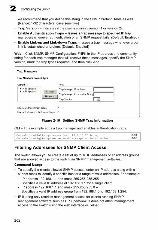
Command Attributes• Trap Manager Capability – Indicates that the switch supports up to five trap
managers.• Current – Displays a list of the trap managers currently configured.• Trap Manager IP Address – IP address of a new management station to receive
trap messages.• Trap Manager Community String – Specifies a valid community string for the
new trap manager entry. Though you can set this string in the Trap Managers table,
Console(config)#snmp-server community spiderman rw 3-93Console(config)#
Configuring the Switch
2-22
2we recommend that you define this string in the SNMP Protocol table as well.(Range: 1-32 characters, case sensitive)
• Trap Version – Indicates if the user is running version 1 or version 2c.• Enable Authentication Traps – Issues a trap message to specified IP trap
managers whenever authentication of an SNMP request fails. (Default: Enabled)• Enable Link-up and Link-down Traps – Issues a trap message whenever a port
link is established or broken. (Default: Enabled)
Web – Click SNMP, SNMP Configuration. FillFill in the IP address and community string for each trap manager that will receive these messages, specify the SNMP version, mark the trap types required, and then click Add.
Figure 2-16 Setting SNMP Trap Information
CLI – This example adds a trap manager and enables authentication traps.
Filtering Addresses for SNMP Client AccessThe switch allows you to create a list of up to 16 IP addresses or IP address groups that are allowed access to the switch via SNMP management software.Command Usage• To specify the clients allowed SNMP access, enter an IP address along with a
subnet mask to identify a specific host or a range of valid addresses. For example:- IP address 192.168.1.1 and mask 255.255.255.255 –
Specifies a valid IP address of 192.168.1.1 for a single client.- IP address 192.168.1.1 and mask 255.255.255.0 –
Specifies a valid IP address group from 192.168.1.0 to 192.168.1.254. • IP filtering only restricts management access for clients running SNMP
management software such as HP OpenView. It does not affect management access to the switch using the web interface or Telnet.
Console(config)#snmp-server host 10.1.19.23 batman 3-94Console(config)#snmp-server enable traps authentication 3-95
Configuring SNMP
2-23
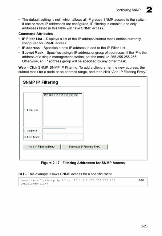
2• The default setting is null, which allows all IP groups SNMP access to the switch.
If one or more IP addresses are configured, IP filtering is enabled and only addresses listed in this table will have SNMP access.
Command Attributes• IP Filter List – Displays a list of the IP address/subnet mask entries currently
configured for SNMP access.• IP address – Specifies a new IP address to add to the IP Filter List.• Subnet Mask – Specifies a single IP address or group of addresses. If the IP is the
address of a single management station, set the mask to 255.255.255.255. Otherwise, an IP address group will be specified by any other mask.
Web – Click SNMP, SNMP IP Filtering. To add a client, enter the new address, the subnet mask for a node or an address range, and then click “Add IP Filtering Entry.”
Figure 2-17 Filtering Addresses for SNMP Access
CLI – This example allows SNMP access for a specific client.
Console(config)#snmp ip filter 10.1.2.3 255.255.255.255 3-97Console(config)#
Configuring the Switch
2-24
2User AuthenticationYou can restrict management access to this switch using the following options:
• Passwords – Manually configure access rights on the switch for specified users.• Authentication Settings – Use remote authentication to configure access rights.• HTTPS Settings – Provide a secure web connection.• SSH Settings – Provide a secure shell (for secure Telnet access).• Port Security – Configure secure addresses for individual ports.• dot1X – Use IEEE 802.1x port authentication to control access to specific ports.
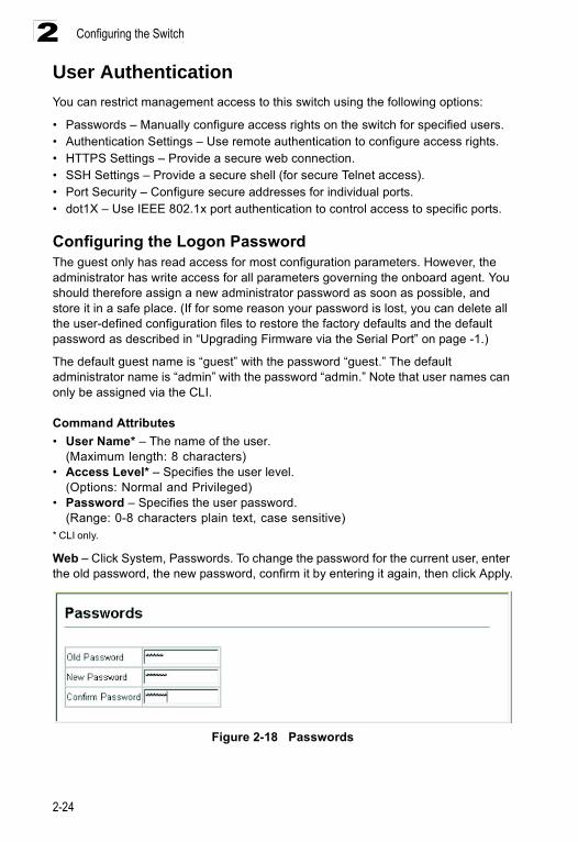
Configuring the Logon PasswordThe guest only has read access for most configuration parameters. However, the administrator has write access for all parameters governing the onboard agent. You should therefore assign a new administrator password as soon as possible, and store it in a safe place. (If for some reason your password is lost, you can delete all the user-defined configuration files to restore the factory defaults and the default password as described in “Upgrading Firmware via the Serial Port” on page -1.)
The default guest name is “guest” with the password “guest.” The default administrator name is “admin” with the password “admin.” Note that user names can only be assigned via the CLI.
Command Attributes• User Name* – The name of the user.
(Maximum length: 8 characters)• Access Level* – Specifies the user level.
(Options: Normal and Privileged)• Password – Specifies the user password.
(Range: 0-8 characters plain text, case sensitive)* CLI only.
Web – Click System, Passwords. To change the password for the current user, enter the old password, the new password, confirm it by entering it again, then click Apply.
Figure 2-18 Passwords
User Authentication
2-25
2CLI – Assign a user name to access-level 15 (i.e., administrator), then specify the password.
Configuring RADIUS/TACACS Logon Authentication Use the Authentication Settings menu to restrict management access based on specified user names and passwords. You can manually configure access rights on the switch, or you can use a remote access authentication server based on RADIUS or TACACS+ protocols.
Remote Authentication Dial-in User Service (RADIUS) and Terminal Access Controller Access Control System Plus (TACACS+) are logon authentication protocols that use software running on a central server to control access to RADIUS-aware or TACACS- aware devices on the network. An authentication server contains a database of multiple user name/password pairs with associated privilege levels for each user that requires management access to the switch.
RADIUS uses UDP while TACACS+ uses TCP. UDP only offers best effort delivery, while TCP offers a connection-oriented transport. Also, note that RADIUS encrypts only the password in the access-request packet from the client to the server, while TACACS+ encrypts the entire body of the packet.
Command Usage• By default, management access is always checked against the authentication
database stored on the local switch. If a remote authentication server is used, you must specify the authentication sequence and the corresponding parameters for the remote authentication protocol. Local and remote logon authentication control management access via the console port, web browser, or Telnet.
• RADIUS uses UDP while TACACS+ uses TCP. UDP only offers best effort delivery, while TCP offers a connection-oriented transport. Also, note that RADIUS encrypts only the password in the access-request packet from the client to the server, while TACACS+ encrypts the entire body of the packet.
• RADIUS and TACACS+ logon authentication assign a specific privilege level for each user name/password pair. The user name, password, and privilege level must be configured on the authentication server.
• You can specify up to three authentication methods for any user to indicate the authentication sequence. For example, if you select (1) RADIUS, (2) TACACS+ and (3) Local, the user name and password on the RADIUS server is verified first. If the RADIUS server is not available, then authentication is attempted using the TACACS+ server, and finally the local user name and password is checked.
Command Attributes• Authentication – Select the authentication, or authentication sequence required:
- Local – User authentication is performed only locally by the switch.- Radius – User authentication is performed using a RADIUS server only.
Console(config)#username bill access-level 15 3-24Console(config)#username bill password 0 1Console(config)#
Configuring the Switch
2-26
2- TACACS – User authentication is performed using a TACACS+ server only.- [authentication sequence] – User authentication is performed by up to three
authentication methods in the indicated sequence.
• RADIUS Settings• Global / ServerIndex – Enables RADIUS on all ports or by server index 1 - 5.• Server IP Address – Address of the RADIUS server. (Default: 10.1.0.1)• Server Port Number – Network (UDP) port of the RADIUS server used for
authentication messages. (Range: 1-65535; Default: 1812)• Secret Text String – Encryption key used to authenticate logon access for client.
Do not use blank spaces in the string. (Maximum length: 20 characters)• Number of Server Transmits – Number of times the switch will try to authenticate
logon access via the RADIUS server. (Range: 1-30; Default: 2)• Timeout for a reply – The number of seconds the switch waits for a reply from the
RADIUS server before it resends the request. (Range: 1-65535; Default: 5)
• TACACS Settings- Server IP Address – Address of the TACACS+ server. (Default: 10.11.12.13)- Server Port Number – Network (TCP) port of TACACS+ server used for
authentication messages. (Range: 1-65535; Default: 49)- Secret Text String – Encryption key used to authenticate logon access for
client. Do not use blank spaces in the string. (Maximum length: 20 characters)
Note: The local switch user database has to be set up by manually entering user names and passwords using the CLI. (See “username” on page 3-24.)
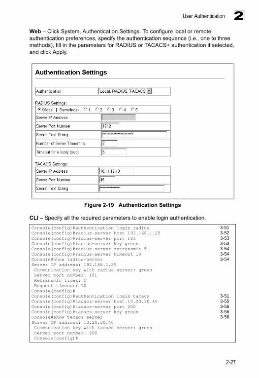
User Authentication
2-27
2Web – Click System, Authentication Settings. To configure local or remote authentication preferences, specify the authentication sequence (i.e., one to three methods), fill in the parameters for RADIUS or TACACS+ authentication if selected, and click Apply.
Figure 2-19 Authentication Settings
CLI – Specify all the required parameters to enable login authentication.
Console(config)#authentication login radius 3-51Console(config)#radius-server host 192.168.1.25 3-52Console(config)#radius-server port 181 3-53Console(config)#radius-server key green 3-53Console(config)#radius-server retransmit 5 3-54Console(config)#radius-server timeout 10 3-54Console#show radius-server 3-54Server IP address: 192.168.1.25 Communication key with radius server: green Server port number: 181 Retransmit times: 5 Request timeout: 10Console(config)#Console(config)#authentication login tacacs 3-51Console(config)#tacacs-server host 10.20.30.40 3-55Console(config)#tacacs-server port 200 3-56Console(config)#tacacs-server key green 3-56Console#show tacacs-server 3-56Server IP address: 10.20.30.40 Communication key with tacacs server: green Server port number: 200 Console(config)#
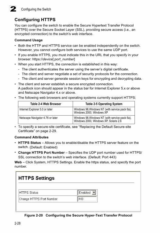
Configuring the Switch
2-28
2Configuring HTTPSYou can configure the switch to enable the Secure Hypertext Transfer Protocol (HTTPS) over the Secure Socket Layer (SSL), providing secure access (i.e., an encrypted connection) to the switch’s web interface.
Command Usage• Both the HTTP and HTTPS service can be enabled independently on the switch.
However, you cannot configure both services to use the same UDP port.• If you enable HTTPS, you must indicate this in the URL that you specify in your
browser: https://device[:port_number]• When you start HTTPS, the connection is established in this way:
- The client authenticates the server using the server’s digital certificate.- The client and server negotiate a set of security protocols for the connection.- The client and server generate session keys for encrypting and decrypting data.
• The client and server establish a secure encrypted connection.A padlock icon should appear in the status bar for Internet Explorer 5.x or above and Netscape Navigator 4.x or above.
• The following web browsers and operating systems currently support HTTPS:
• To specify a secure-site certificate, see “Replacing the Default Secure-site Certificate” on page 2-29.
Command Attributes• HTTPS Status – Allows you to enable/disable the HTTPS server feature on the
switch. (Default: Enabled)• Change HTTPS Port Number – Specifies the UDP port number used for HTTPS/
SSL connection to the switch’s web interface. (Default: Port 443)Web – Click System, HTTPS Settings. Enable the https status, and specify the port number.
Figure 2-20 Configuring the Secure Hyper-Text Transfer Protocol
Table 2-4 Web Browser Table 2-5 Operating SystemInternet Explorer 5.0 or later Windows 98,Windows NT (with service pack 6a),
Windows 2000, Windows XPNetscape Navigator 4.76 or later Windows 98,Windows NT (with service pack 6a),
Windows 2000, Windows XP, Solaris 2.6
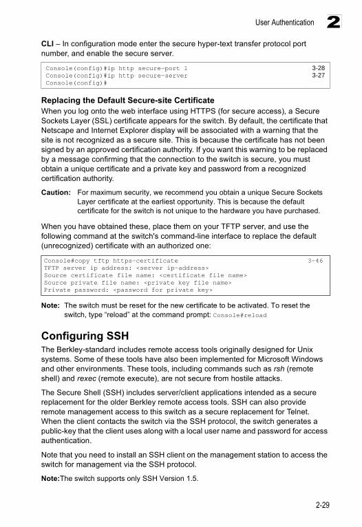
User Authentication
2-29
2CLI – In configuration mode enter the secure hyper-text transfer protocol port number, and enable the secure server.
Replacing the Default Secure-site CertificateWhen you log onto the web interface using HTTPS (for secure access), a Secure Sockets Layer (SSL) certificate appears for the switch. By default, the certificate that Netscape and Internet Explorer display will be associated with a warning that the site is not recognized as a secure site. This is because the certificate has not been signed by an approved certification authority. If you want this warning to be replaced by a message confirming that the connection to the switch is secure, you must obtain a unique certificate and a private key and password from a recognized certification authority.
Caution: For maximum security, we recommend you obtain a unique Secure Sockets Layer certificate at the earliest opportunity. This is because the default certificate for the switch is not unique to the hardware you have purchased.
When you have obtained these, place them on your TFTP server, and use the following command at the switch's command-line interface to replace the default (unrecognized) certificate with an authorized one:
Note: The switch must be reset for the new certificate to be activated. To reset the switch, type “reload” at the command prompt: Console#reload
Configuring SSH The Berkley-standard includes remote access tools originally designed for Unix systems. Some of these tools have also been implemented for Microsoft Windows and other environments. These tools, including commands such as rsh (remote shell) and rexec (remote execute), are not secure from hostile attacks.
The Secure Shell (SSH) includes server/client applications intended as a secure replacement for the older Berkley remote access tools. SSH can also provide remote management access to this switch as a secure replacement for Telnet. When the client contacts the switch via the SSH protocol, the switch generates a public-key that the client uses along with a local user name and password for access authentication.
Note that you need to install an SSH client on the management station to access the switch for management via the SSH protocol.
Note:The switch supports only SSH Version 1.5.
Console(config)#ip http secure-port 1 3-28Console(config)#ip http secure-server 3-27Console(config)#
Console#copy tftp https-certificate 3-46TFTP server ip address: <server ip-address>Source certificate file name: <certificate file name>Source private file name: <private key file name>Private password: <password for private key>
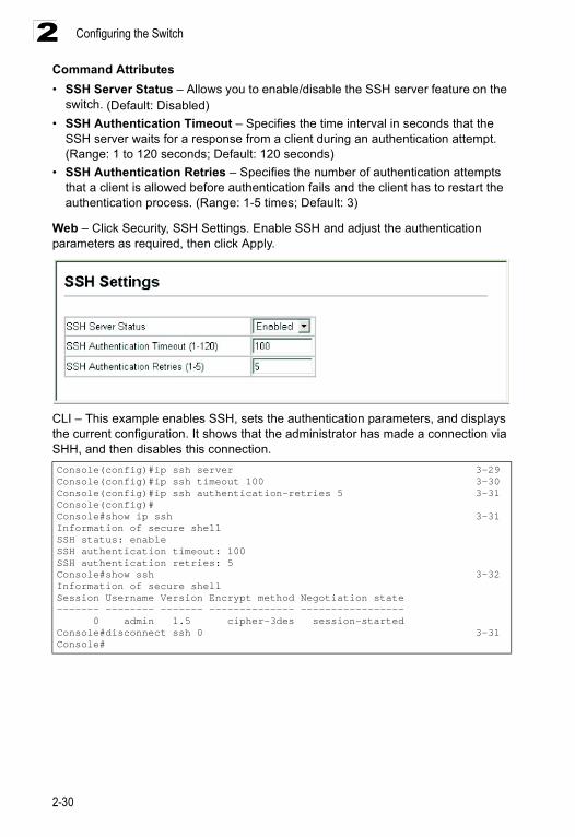
Configuring the Switch
2-30
2Command Attributes• SSH Server Status – Allows you to enable/disable the SSH server feature on the
switch. (Default: Disabled)• SSH Authentication Timeout – Specifies the time interval in seconds that the
SSH server waits for a response from a client during an authentication attempt.(Range: 1 to 120 seconds; Default: 120 seconds)
• SSH Authentication Retries – Specifies the number of authentication attempts that a client is allowed before authentication fails and the client has to restart the authentication process. (Range: 1-5 times; Default: 3)
Web – Click Security, SSH Settings. Enable SSH and adjust the authentication parameters as required, then click Apply.
CLI – This example enables SSH, sets the authentication parameters, and displays the current configuration. It shows that the administrator has made a connection via SHH, and then disables this connection.Console(config)#ip ssh server 3-29Console(config)#ip ssh timeout 100 3-30Console(config)#ip ssh authentication-retries 5 3-31Console(config)#Console#show ip ssh 3-31Information of secure shellSSH status: enableSSH authentication timeout: 100SSH authentication retries: 5Console#show ssh 3-32Information of secure shellSession Username Version Encrypt method Negotiation state------- -------- ------- -------------- ----------------- 0 admin 1.5 cipher-3des session-startedConsole#disconnect ssh 0 3-31Console#
User Authentication
2-31
2Configuring Port SecurityPort security is a feature that allows you to configure a switch port with one or more device MAC addresses that are authorized to access the network through that port.
When port security is enabled on a port, the switch stops learning new MAC addresses on the specified port. Only incoming traffic with source addresses already stored in the dynamic or static address table will be accepted as authorized to access the network through that port. If a device with an unauthorized MAC address attempts to use the switch port, the intrusion will be detected and the switch can automatically take action by disabling the port and sending a trap message.
To use port security, first allow the switch to dynamically learn the <source MAC address, VLAN> pair for frames received on a port for an initial training period, and then enable port security to stop address learning. Be sure you enable the learning function long enough to ensure that all valid VLAN members have been registered on the selected port. Note that you can also restrict the maximum number of addresses that can be learned by a port.
To add new VLAN members at a later time, you can manually add secure addresses with the Static Address Table (page 2-68), or turn off port security to reenable the learning function long enough for new VLAN members to be registered. Learning may then be disabled again, if desired, for security.
Command Usage• A secure port has the following restrictions:
- Cannot use port monitoring. - Cannot be a multi-VLAN port. - It cannot be used as a member of a static or dynamic trunk.- It should not be connected to a network interconnection device.
• If a port is disabled (shut down) due to a security violation, it must be manually re-enabled from the Port/Port Configuration page (page 2-54).
Command Attributes• Port – Port number.• Action* – Indicates the action to be taken when a port security violation is detected:
- None: No action should be taken. (This is the default.)- Trap: Send an SNMP trap message.- Shutdown: Disable the port.- Trap and Shutdown: Send an SNMP trap message and disable the port.
• Status – Enables or disables port security on the port. (Default: Disabled)• Max MAC Count – The maximum number of MAC addresses that can be learned
on a port. (Range: 0 - 20)* CLI only.
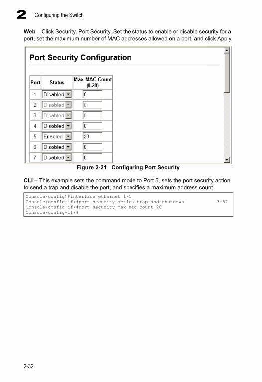
Configuring the Switch
2-32
2Web – Click Security, Port Security. Set the status to enable or disable security for a port, set the maximum number of MAC addresses allowed on a port, and click Apply.
Figure 2-21 Configuring Port Security
CLI – This example sets the command mode to Port 5, sets the port security action to send a trap and disable the port, and specifies a maximum address count.Console(config)#interface ethernet 1/5Console(config-if)#port security action trap-and-shutdown 3-57Console(config-if)#port security max-mac-count 20Console(config-if)#
User Authentication
2-33
2Configuring 802.1x Port AuthenticationNetwork switches can provide open and easy access to network resources by simply attaching a client PC. Although this automatic configuration and access is a desirable feature, it also allows unauthorized personnel to easily intrude and possibly gain access to sensitive network data.
The IEEE 802.1x standard defines a port-based access control procedure that prevents unauthorized access to a network by requiring users to first enter a user ID and password for authentication. Access to all switch ports in a network can be centrally controlled from a server, which means that authorized users can use a single user ID and password for authentication from any point within the network.
This switch uses the Extensible Authentication Protocol over LANs (EAPOL) to exchange authentication protocol messages with the client, and a remote RADIUS authentication server to verify user identity and access rights. When a client (i.e., Supplicant) connects to a switch port, the switch (i.e., Authenticator) responds with an EAPOL identity request. The client provides its identity (such as a user name) in an EAPOL response to the switch, which it forwards to the RADIUS server. The RADIUS server verifies the client identity and sends an access challenge back to the client. The EAP packet from the RADIUS server contains not only the challenge, but the authentication method to be used. The client can reject the authentication method and request another, depending on the configuration of the client software and the RADIUS server. The authentication method can be MD5, TLS (Transport Layer Security), TTLS (Tunneled Transport Layer Security), or other. The client responds to the appropriate method with its credentials, such as a password or certificate. The RADIUS server verifies the client credentials and responds with an accept or reject packet. If authentication is successful, the switch allows the client to access the network. Otherwise, network access is denied and the port remains blocked.
The operation of dot1x on the switch requires the following:
• The switch must have an IP address assigned.• RADIUS authentication must be enabled on the switch and the IP address of the
RADIUS server specified.• Each switch port that will be used must be set to dot1x “Auto” mode.• Each client that needs to be authenticated must have dot1x client software
installed and properly configured.• The RADIUS server must support EAPOL and MD5, TLS or TTLS authentication.
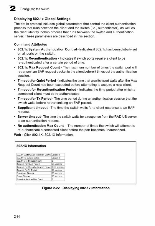
Configuring the Switch
2-34
2Displaying 802.1x Global SettingsThe dot1x protocol includes global parameters that control the client authentication process that runs between the client and the switch (i.e., authenticator), as well as the client identity lookup process that runs between the switch and authentication server. These parameters are described in this section.
Command Attributes• 802.1x System Authentication Control - Indicates if 802.1x has been globally set
on all ports on the switch.• 802.1x Re-authentication - Indicates if switch ports require a client to be
re-authenticated after a certain period of time.• 802.1x Max Request Count - The maximum number of times the switch port will
retransmit an EAP request packet to the client before it times out the authentication session.
• Timeout for Quiet Period - Indicates the time that a switch port waits after the Max Request Count has been exceeded before attempting to acquire a new client.
• Timeout for Re-authentication Period - Indicates the time period after which a connected client must be re-authenticated.
• Timeout for Tx Period - The time period during an authentication session that the switch waits before re-transmitting an EAP packet.
• Supplicant timeout - The time the switch waits for a client response to an EAP request.
• Server timeout - The time the switch waits for a response from the RADIUS server to an authentication request.
• Re-authentication Max Count - The number of times the switch will attempt to re-authenticate a connected client before the port becomes unauthorized.
Web - Click 802.1X, 802.1X Information.
Figure 2-22 Displaying 802.1x Information
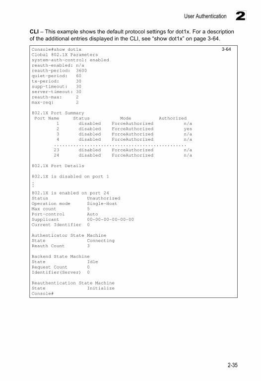
User Authentication
2-35
2CLI – This example shows the default protocol settings for dot1x. For a description of the additional entries displayed in the CLI, see “show dot1x” on page 3-64.
Console#show dot1x 3-64Clobal 802.1X Parameterssystem-auth-control: enabledreauth-enabled: n/areauth-period: 3600quiet-period: 60tx-period: 30supp-timeout: 30server-timeout: 30reauth-max: 2max-req: 2
802.1X Port Summary Port Name Status Mode Authorized 1 disabled ForceAuthorized n/a 2 disabled ForceAuthorized yes 3 disabled ForceAuthorized n/a 4 disabled ForceAuthorized n/a ................................................ 23 disabled ForceAuthorized n/a 24 disabled ForceAuthorized n/a
802.1X Port Details
802.1X is disabled on port 1...
802.1X is enabled on port 24Status UnauthorizedOperation mode Single-HostMax count 5Port-control AutoSupplicant 00-00-00-00-00-00Current Identifier 0
Authenticator State MachineState ConnectingReauth Count 3
Backend State MachineState IdleRequest Count 0Identifier(Server) 0
Reauthentication State MachineState InitializeConsole#
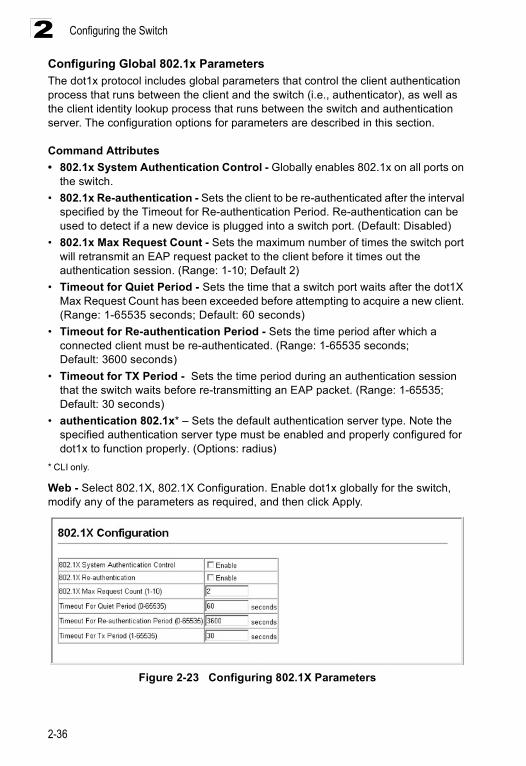
Configuring the Switch
2-36
2Configuring Global 802.1x Parameters The dot1x protocol includes global parameters that control the client authentication process that runs between the client and the switch (i.e., authenticator), as well as the client identity lookup process that runs between the switch and authentication server. The configuration options for parameters are described in this section.
Command Attributes• 802.1x System Authentication Control - Globally enables 802.1x on all ports on
the switch.• 802.1x Re-authentication - Sets the client to be re-authenticated after the interval
specified by the Timeout for Re-authentication Period. Re-authentication can be used to detect if a new device is plugged into a switch port. (Default: Disabled)
• 802.1x Max Request Count - Sets the maximum number of times the switch port will retransmit an EAP request packet to the client before it times out the authentication session. (Range: 1-10; Default 2)
• Timeout for Quiet Period - Sets the time that a switch port waits after the dot1X Max Request Count has been exceeded before attempting to acquire a new client. (Range: 1-65535 seconds; Default: 60 seconds)
• Timeout for Re-authentication Period - Sets the time period after which a connected client must be re-authenticated. (Range: 1-65535 seconds; Default: 3600 seconds)
• Timeout for TX Period - Sets the time period during an authentication session that the switch waits before re-transmitting an EAP packet. (Range: 1-65535; Default: 30 seconds)
• authentication 802.1x* – Sets the default authentication server type. Note the specified authentication server type must be enabled and properly configured for dot1x to function properly. (Options: radius)
* CLI only.
Web - Select 802.1X, 802.1X Configuration. Enable dot1x globally for the switch, modify any of the parameters as required, and then click Apply..
Figure 2-23 Configuring 802.1X Parameters
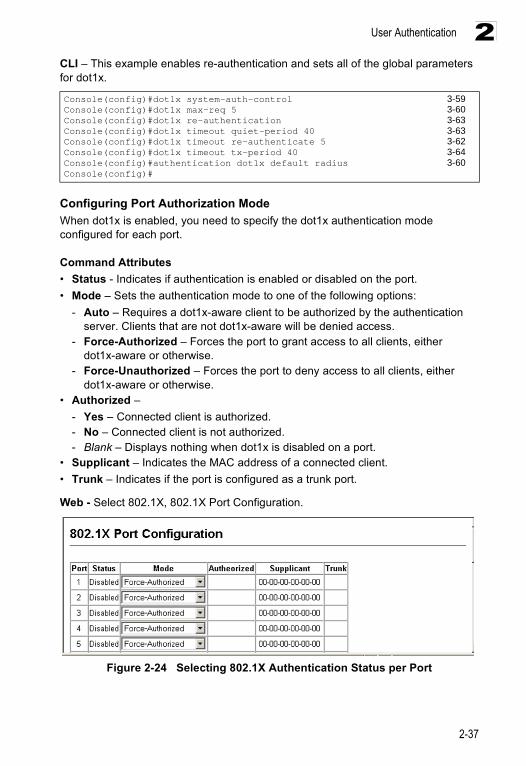
User Authentication
2-37
2CLI – This example enables re-authentication and sets all of the global parameters for dot1x.
Configuring Port Authorization ModeWhen dot1x is enabled, you need to specify the dot1x authentication mode configured for each port.
Command Attributes• Status - Indicates if authentication is enabled or disabled on the port.• Mode – Sets the authentication mode to one of the following options:
- Auto – Requires a dot1x-aware client to be authorized by the authentication server. Clients that are not dot1x-aware will be denied access.
- Force-Authorized – Forces the port to grant access to all clients, either dot1x-aware or otherwise.
- Force-Unauthorized – Forces the port to deny access to all clients, either dot1x-aware or otherwise.
• Authorized – - Yes – Connected client is authorized.- No – Connected client is not authorized.- Blank – Displays nothing when dot1x is disabled on a port.
• Supplicant – Indicates the MAC address of a connected client.• Trunk – Indicates if the port is configured as a trunk port.
Web - Select 802.1X, 802.1X Port Configuration.
Figure 2-24 Selecting 802.1X Authentication Status per Port
Console(config)#dot1x system-auth-control 3-59Console(config)#dot1x max-req 5 3-60Console(config)#dot1x re-authentication 3-63Console(config)#dot1x timeout quiet-period 40 3-63Console(config)#dot1x timeout re-authenticate 5 3-62Console(config)#dot1x timeout tx-period 40 3-64Console(config)#authentication dot1x default radius 3-60Console(config)#
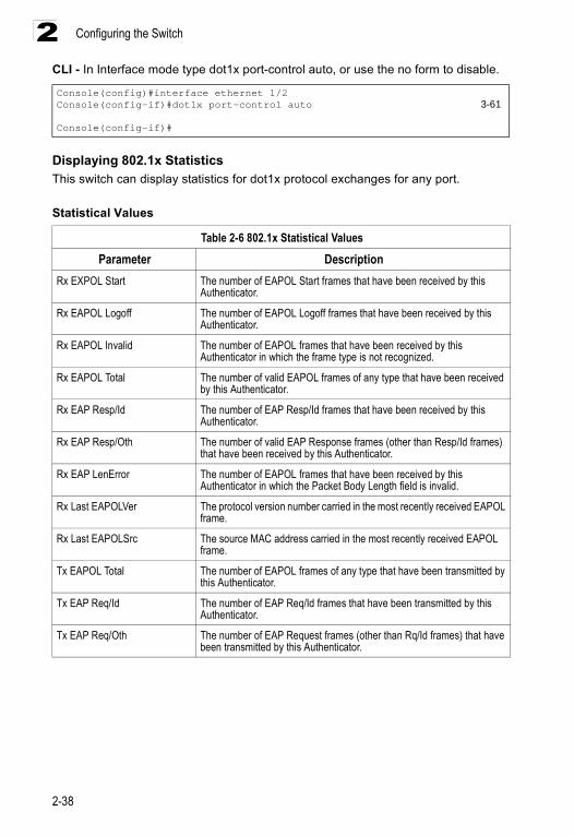
Configuring the Switch
2-38
2CLI - In Interface mode type dot1x port-control auto, or use the no form to disable.
Displaying 802.1x StatisticsThis switch can display statistics for dot1x protocol exchanges for any port.
Statistical Values
Console(config)#interface ethernet 1/2Console(config-if)#dot1x port-control auto 3-61
Console(config-if)#
Table 2-6 802.1x Statistical Values
Parameter DescriptionRx EXPOL Start The number of EAPOL Start frames that have been received by this
Authenticator.
Rx EAPOL Logoff The number of EAPOL Logoff frames that have been received by this Authenticator.
Rx EAPOL Invalid The number of EAPOL frames that have been received by this Authenticator in which the frame type is not recognized.
Rx EAPOL Total The number of valid EAPOL frames of any type that have been received by this Authenticator.
Rx EAP Resp/Id The number of EAP Resp/Id frames that have been received by this Authenticator.
Rx EAP Resp/Oth The number of valid EAP Response frames (other than Resp/Id frames) that have been received by this Authenticator.
Rx EAP LenError The number of EAPOL frames that have been received by this Authenticator in which the Packet Body Length field is invalid.
Rx Last EAPOLVer The protocol version number carried in the most recently received EAPOL frame.
Rx Last EAPOLSrc The source MAC address carried in the most recently received EAPOL frame.
Tx EAPOL Total The number of EAPOL frames of any type that have been transmitted by this Authenticator.
Tx EAP Req/Id The number of EAP Req/Id frames that have been transmitted by this Authenticator.
Tx EAP Req/Oth The number of EAP Request frames (other than Rq/Id frames) that have been transmitted by this Authenticator.
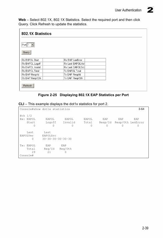
User Authentication
2-39
2Web – Select 802.1X, 802.1X Statistics. Select the required port and then click Query. Click Refresh to update the statistics.
Figure 2-25 Displaying 802.1X EAP Statistics per Port
CLI – This example displays the dot1x statistics for port 2.Console#show dot1x statistics 3-64
Eth 1/2Rx: EXPOL EAPOL EAPOL EAPOL EAP EAP EAP Start Logoff Invalid Total Resp/Id Resp/Oth LenError 0 0 0 0 0 0 0
Last LastEAPOLVer EAPOLSrc 0 30-30-30-30-30-30
Tx: EAPOL EAP EAP Total Req/Id Req/Oth 29 21 0Console#
Configuring the Switch
2-40
2Access Control ListsAccess Control Lists (ACL) provide packet filtering for IP frames (based on address, protocol, Layer 4 protocol port number or TCP control code) or any frames (based on MAC address or Ethernet type). To filter incoming packets, first create an access list, add the required rules, specify a mask to modify the precedence in which the rules are checked, and then bind the list to a specific port.
Configuring Access Control ListsAn ACL is a sequential list of permit or deny conditions that apply to IP addresses, MAC addresses, or other more specific criteria. This switch tests ingress or egress packets against the conditions in an ACL one by one. A packet will be accepted as soon as it matches a permit rule, or dropped as soon as it matches a deny rule. If no rules match for a list of all permit rules, the packet is dropped; and if no rules match for a list of all deny rules, the packet is accepted.
Command Usage
The following restrictions apply to ACLs:• Each ACL can have up to 32 rules.• The maximum number of ACLs is also 32.• However, due to resource restrictions, the average number of rules bound to the
ports should not exceed 20.• You must configure a mask for an ACL rule before you can bind it to a port or set
the queue or frame priorities associated with the rule.• When an ACL is bound to an interface as an egress filter, all entries in the ACL
must be deny rules. Otherwise, the bind operation will fail.• The switch does not support the explicit “deny any any” rule for the egress IP ACL
or the egress MAC ACLs. If these rules are included in ACL, and you attempt to bind the ACL to an interface for egress checking, the bind operation will fail.
The order in which active ACLs are checked is as follows:1. User-defined rules in the Egress MAC ACL for egress ports.2. User-defined rules in the Egress IP ACL for egress ports.3. User-defined rules in the Ingress MAC ACL for ingress ports.4. User-defined rules in the Ingress IP ACL for ingress ports.5. Explicit default rule (permit any any) in the ingress IP ACL for ingress ports.6. Explicit default rule (permit any any) in the ingress MAC ACL for ingress ports.7. If no explicit rule is matched, the implicit default is permit all.
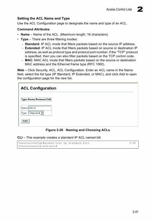
Access Control Lists
2-41
2Setting the ACL Name and TypeUse the ACL Configuration page to designate the name and type of an ACL.
Command Attributes• Name – Name of the ACL. (Maximum length: 16 characters)• Type – There are three filtering modes:
- Standard: IP ACL mode that filters packets based on the source IP address. - Extended: IP ACL mode that filters packets based on source or destination IP
address, as well as protocol type and protocol port number. If the “TCP” protocol is specified, then you can also filter packets based on the TCP control code.
- MAC: MAC ACL mode that filters packets based on the source or destination MAC address and the Ethernet frame type (RFC 1060).
Web – Click Security, ACL, ACL Configuration. Enter an ACL name in the Name field, select the list type (IP Standard, IP Extended, or MAC), and click Add to open the configuration page for the new list.
Figure 2-26 Naming and Choosing ACLs
CLI – This example creates a standard IP ACL named bill.Console(config)#access-list ip standard bill 3-69Console(config-std-acl)#
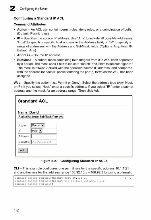
Configuring the Switch
2-42
2Configuring a Standard IP ACLCommand Attributes• Action – An ACL can contain permit rules, deny rules, or a combination of both.
(Default: Permit rules)• IP – Specifies the source IP address. Use “Any” to include all possible addresses,
“Host” to specify a specific host address in the Address field, or “IP” to specify a range of addresses with the Address and SubMask fields. (Options: Any, Host, IP; Default: Any)
• Address – Source IP address.• SubMask – A subnet mask containing four integers from 0 to 255, each separated
by a period. The mask uses 1 bits to indicate “match” and 0 bits to indicate “ignore.” The mask is bitwise ANDed with the specified source IP address, and compared with the address for each IP packet entering the port(s) to which this ACL has been assigned.
Web – Specify the action (i.e., Permit or Deny). Select the address type (Any, Host, or IP). If you select “Host,” enter a specific address. If you select “IP,” enter a subnet address and the mask for an address range. Then click Add.
Figure 2-27 Configuring Standard IP ACLs
CLI – This example configures one permit rule for the specific address 10.1.1.21 and another rule for the address range 168.92.16.x – 168.92.31.x using a bitmask.Console(config-std-acl)#permit host 10.1.1.21 3-70Console(config-std-acl)#permit 168.92.16.0 255.255.240.0Console(config-std-acl)#
Access Control Lists
2-43
2Configuring an Extended IP ACLCommand Attributes• Action – An ACL can contain permit rules, deny rules or a combination of both.
(Default: Permit rules)• Src/Dst IP – Specifies the source or destination IP address. Use “Any” to include
all possible addresses, “Host” to specify a specific host address in the Address field, or “IP” to specify a range of addresses with the Address and SubMask fields. (Options: Any, Host, IP; Default: Any)
• Src/Dst Address – Source or destination IP address.• Src/Dst SubMask – Subnet mask for source or destination address. (See the
description for SubMask on page 2-42.)• Service Type – Packet priority settings based on the following criteria:
- Precedence – IP precedence level. (Range: 0-7)- TOS – Type of Service level. (Range: 0-15)- DSCP – DSCP priority level. (Range: 0-64)
• Protocol – Specifies the protocol type to match as TCP, UDP or Others, where others indicates a specific protocol number (0-255). (Options: TCP, UDP, Others; Default: TCP)
• Src/Dst Port – Source/destination port number for the specified protocol type. (Range: 0-65535)
• Src/Dst Port Bitmask – Decimal number representing the port bits to match. (Range: 0-65535)
• Control Code – Decimal number (representing a bit string) that specifies flag bits in byte 14 of the TCP header. (Range: 0-63)
• Control Bitmask – Decimal number representing the code bits to match.The control bitmask is a decimal number (for an equivalent binary bit mask) that is applied to the control code. Enter a decimal number, where the equivalent binary bit “1” means to match a bit and “0” means to ignore a bit. The following bits may be specified:- 1 (fin) – Finish- 2 (syn) – Synchronize- 4 (rst) – Reset- 8 (psh) – Push- 16 (ack) – Acknowledgement- 32 (urg) – Urgent pointer
For example, use the code value and mask below to catch packets with the following flags set: - SYN flag valid, use control-code 2, control bitmask 2- Both SYN and ACK valid, use control-code 18, control bitmask 18- SYN valid and ACK invalid, use control-code 2, control bitmask 18
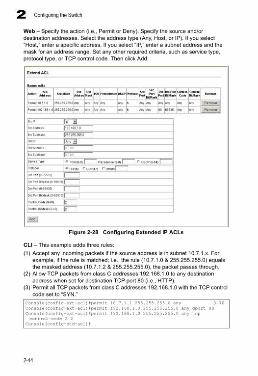
Configuring the Switch
2-44
2Web – Specify the action (i.e., Permit or Deny). Specify the source and/or destination addresses. Select the address type (Any, Host, or IP). If you select “Host,” enter a specific address. If you select “IP,” enter a subnet address and the mask for an address range. Set any other required criteria, such as service type, protocol type, or TCP control code. Then click Add.
Figure 2-28 Configuring Extended IP ACLs
CLI – This example adds three rules:(1) Accept any incoming packets if the source address is in subnet 10.7.1.x. For
example, if the rule is matched; i.e., the rule (10.7.1.0 & 255.255.255.0) equals the masked address (10.7.1.2 & 255.255.255.0), the packet passes through.
(2) Allow TCP packets from class C addresses 192.168.1.0 to any destination address when set for destination TCP port 80 (i.e., HTTP).
(3) Permit all TCP packets from class C addresses 192.168.1.0 with the TCP control code set to “SYN.”
Console(config-ext-acl)#permit 10.7.1.1 255.255.255.0 any 3-70Console(config-ext-acl)#permit 192.168.1.0 255.255.255.0 any dport 80Console(config-ext-acl)#permit 192.168.1.0 255.255.255.0 any tcp control-code 2 2
Console(config-std-acl)#
Access Control Lists
2-45
2Configuring a MAC ACLCommand Attributes• Action – An ACL can contain permit rules, deny rules, or a combination of both.
(Default: Permit rules)• Source/Destination MAC – Use “Any” to include all possible addresses, “Host” to
indicate a specific MAC address, or “MAC” to specify an address range with the Address and Bitmask fields. (Options: Any, Host, MAC; Default: Any)
• Source/Destination MAC Address – Source or destination MAC address.• Source/Destination MAC Bitmask – Hexidecimal mask for source or destination
MAC address.• VID – VLAN ID. (Range: 1-4095)• VID Mask – VLAN bitmask. (Range: 1-4095)• Ethernet Type – This option can only be used to filter Ethernet II formatted
packets. (Range: 600-fff hex.)A detailed listing of Ethernet protocol types can be found in RFC 1060. A few of the more common types include 0800 (IP), 0806 (ARP), 8137 (IPX).
• Ethernet Type Bitmask – Protocol bitmask. (Range: 600-fff hex.)• Packet Format Bitmask– This attribute includes the following packet types:
• Any – Any Ethernet packet type.• Untagged-eth2 – Untagged Ethernet II packets.• Untagged-802.3 – Untagged Ethernet 802.3 packets.• Tagged-eth2 – Tagged Ethernet II packets.• Tagged-802.3 – Tagged Ethernet 802.3 packets.
Command Usage• Egress MAC ACLs only work for destination-mac-known packets, not for multicast,
broadcast, or destination-mac-unknown packets.
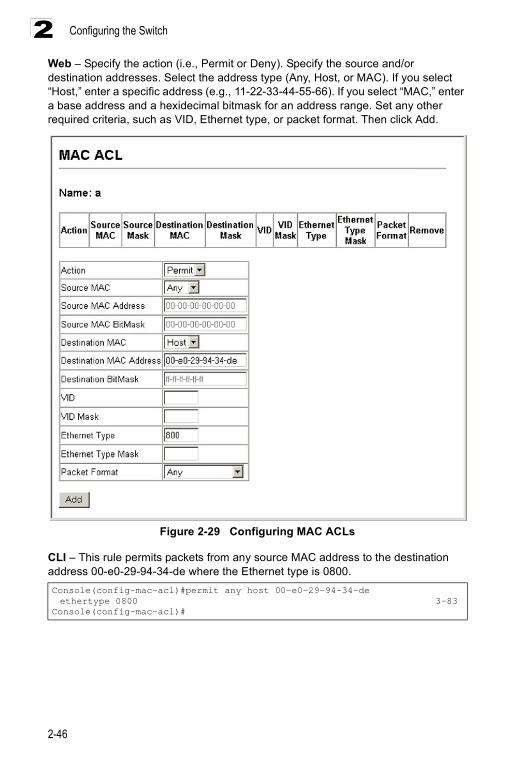
Configuring the Switch
2-46
2Web – Specify the action (i.e., Permit or Deny). Specify the source and/or destination addresses. Select the address type (Any, Host, or MAC). If you select “Host,” enter a specific address (e.g., 11-22-33-44-55-66). If you select “MAC,” enter a base address and a hexidecimal bitmask for an address range. Set any other required criteria, such as VID, Ethernet type, or packet format. Then click Add.
Figure 2-29 Configuring MAC ACLs
CLI – This rule permits packets from any source MAC address to the destination address 00-e0-29-94-34-de where the Ethernet type is 0800.Console(config-mac-acl)#permit any host 00-e0-29-94-34-de ethertype 0800 3-83
Console(config-mac-acl)#
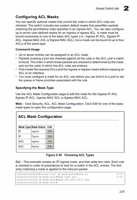
Access Control Lists
2-47
2Configuring ACL MasksYou can specify optional masks that control the order in which ACL rules are checked. The switch includes two system default masks that pass/filter packets matching the permit/deny rules specified in an ingress ACL. You can also configure up to seven user-defined masks for an ingress or egress ACL. A mask must be bound exclusively to one of the basic ACL types (i.e., Ingress IP ACL, Egress IP ACL, Ingress MAC ACL or Egress MAC ACL), but a mask can be bound to up to four ACLs of the same type.
Command Usage
• Up to seven entries can be assigned to an ACL mask.• Packets crossing a port are checked against all the rules in the ACL until a match
is found. The order in which these packets are checked is determined by the mask, and not the order in which the ACL rules are entered.
• First create the required ACLs and the ingress or egress masks before mapping an ACL to an interface.
• You must configure a mask for an ACL rule before you can bind it to a port or set the queue or frame priorities associated with the rule.
Specifying the Mask Type
Use the ACL Mask Configuration page to edit the mask for the Ingress IP ACL, Egress IP ACL, Ingress MAC ACL or Egress MAC ACL.
Web – Click Security, ACL, ACL Mask Configuration. Click Edit for one of the basic mask types to open the configuration page.
Figure 2-30 Choosing ACL Types
CLI – This example creates an IP ingress mask, and then adds two rules. Each rule is checked in order of precedence to look for a match in the ACL entries. The first entry matching a mask is applied to the inbound packet.Console(config)#access-list ip mask-precedence in 3-73Console(config-ip-mask-acl)#mask host any 3-74Console(config-ip-mask-acl)#mask 255.255.255.0 anyConsole(config-ip-mask-acl)#
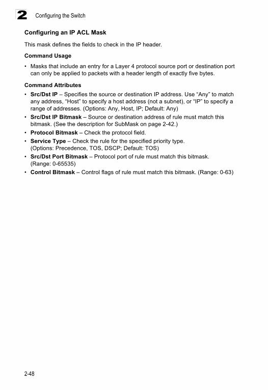
Configuring the Switch
2-48
2Configuring an IP ACL Mask
This mask defines the fields to check in the IP header.
Command Usage
• Masks that include an entry for a Layer 4 protocol source port or destination port can only be applied to packets with a header length of exactly five bytes.
Command Attributes• Src/Dst IP – Specifies the source or destination IP address. Use “Any” to match
any address, “Host” to specify a host address (not a subnet), or “IP” to specify a range of addresses. (Options: Any, Host, IP; Default: Any)
• Src/Dst IP Bitmask – Source or destination address of rule must match this bitmask. (See the description for SubMask on page 2-42.)
• Protocol Bitmask – Check the protocol field.• Service Type – Check the rule for the specified priority type.
(Options: Precedence, TOS, DSCP; Default: TOS)• Src/Dst Port Bitmask – Protocol port of rule must match this bitmask.
(Range: 0-65535)• Control Bitmask – Control flags of rule must match this bitmask. (Range: 0-63)
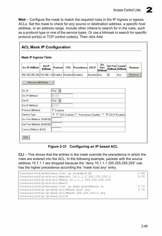
Access Control Lists
2-49
2Web – Configure the mask to match the required rules in the IP ingress or egress ACLs. Set the mask to check for any source or destination address, a specific host address, or an address range. Include other criteria to search for in the rules, such as a protocol type or one of the service types. Or use a bitmask to search for specific protocol port(s) or TCP control code(s). Then click Add.
Figure 2-31 Configuring an IP based ACL
CLI – This shows that the entries in the mask override the precedence in which the rules are entered into the ACL. In the following example, packets with the source address 10.1.1.1 are dropped because the “deny 10.1.1.1 255.255.255.255” rule has the higher precedence according the “mask host any” entry.Console(config)#access-list ip standard A2 3-69Console(config-std-acl)#permit 10.1.1.0 255.255.255.0 3-70Console(config-std-acl)#deny 10.1.1.1 255.255.255.255Console(config-std-acl)#exitConsole(config)#access-list ip mask-precedence in 3-73Console(config-ip-mask-acl)#mask host any 3-74Console(config-ip-mask-acl)#mask 255.255.255.0 anyConsole(config-ip-mask-acl)#
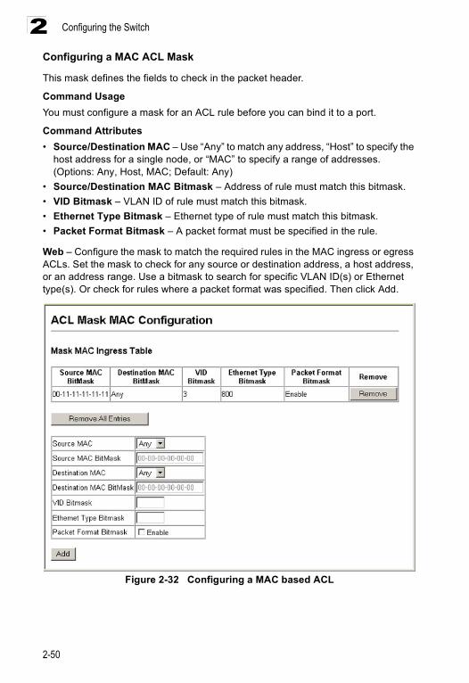
Configuring the Switch
2-50
2Configuring a MAC ACL Mask
This mask defines the fields to check in the packet header.
Command UsageYou must configure a mask for an ACL rule before you can bind it to a port.
Command Attributes• Source/Destination MAC – Use “Any” to match any address, “Host” to specify the
host address for a single node, or “MAC” to specify a range of addresses. (Options: Any, Host, MAC; Default: Any)
• Source/Destination MAC Bitmask – Address of rule must match this bitmask.• VID Bitmask – VLAN ID of rule must match this bitmask.• Ethernet Type Bitmask – Ethernet type of rule must match this bitmask.• Packet Format Bitmask – A packet format must be specified in the rule.
Web – Configure the mask to match the required rules in the MAC ingress or egress ACLs. Set the mask to check for any source or destination address, a host address, or an address range. Use a bitmask to search for specific VLAN ID(s) or Ethernet type(s). Or check for rules where a packet format was specified. Then click Add.
Figure 2-32 Configuring a MAC based ACL
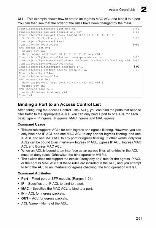
Access Control Lists
2-51
2CLI – This example shows how to create an Ingress MAC ACL and bind it to a port. You can then see that the order of the rules have been changed by the mask.
Binding a Port to an Access Control ListAfter configuring the Access Control Lists (ACL), you can bind the ports that need to filter traffic to the appropriate ACLs. You can only bind a port to one ACL for each basic type – IP ingress, IP egress, MAC ingress and MAC egress.
Command Usage• This switch supports ACLs for both ingress and egress filtering. However, you can
only bind one IP ACL and one MAC ACL to any port for ingress filtering, and one IP ACL and one MAC ACL to any port for egress filtering. In other words, only four ACLs can be bound to an interface – Ingress IP ACL, Egress IP ACL, Ingress MAC ACL and Egress MAC ACL.
• When an ACL is bound to an interface as an egress filter, all entries in the ACL must be deny rules. Otherwise, the bind operation will fail.
• The switch does not support the explicit “deny any any” rule for the egress IP ACL or the egress MAC ACLs. If these rules are included in the ACL, and you attempt to bind the ACL to an interface for egress checking, the bind operation will fail.
Command Attributes• Port – Fixed port or SFP module. (Range: 1-24)• IP – Specifies the IP ACL to bind to a port.• MAC – Specifies the MAC ACL to bind to a port.• IN – ACL for ingress packets.• OUT – ACL for egress packets.• ACL Name – Name of the ACL.
Console(config)#access-list mac M4 3-82Console(config-mac-acl)#permit any any 3-83Console(config-mac-acl)#deny tagged-eth2 00-11-11-11-11-11 ff-ff-ff-ff-ff-ff any vid 3 3-83
Console(config-mac-acl)#endConsole#show access-list 3-91MAC access-list M4: permit any any deny tagged-eth2 host 00-11-11-11-11-11 any vid 3Console(config)#access-list mac mask-precedence in 3-85Console(config-mac-mask-acl)#mask pktformat ff-ff-ff-ff-ff-ff any vid 3-86Console(config-mac-mask-acl)#exitConsole(config)#interface ethernet 1/12 3-99Console(config-if)#mac access-group M4 in 3-88Console(config-if)#endConsole#show access-listMAC access-list M4: deny tagged-eth2 host 00-11-11-11-11-11 any vid 3 permit any anyMAC ingress mask ACL: mask pktformat host any vidConsole#
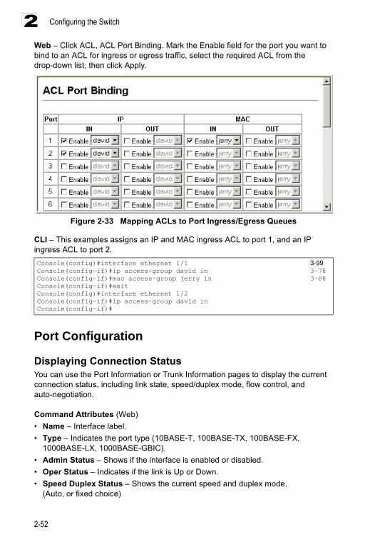
Configuring the Switch
2-52
2Web – Click ACL, ACL Port Binding. Mark the Enable field for the port you want to bind to an ACL for ingress or egress traffic, select the required ACL from the drop-down list, then click Apply.
Figure 2-33 Mapping ACLs to Port Ingress/Egress Queues
CLI – This examples assigns an IP and MAC ingress ACL to port 1, and an IP ingress ACL to port 2.
Port Configuration
Displaying Connection StatusYou can use the Port Information or Trunk Information pages to display the current connection status, including link state, speed/duplex mode, flow control, and auto-negotiation.
Command Attributes (Web)• Name – Interface label.• Type – Indicates the port type (10BASE-T, 100BASE-TX, 100BASE-FX,
1000BASE-LX, 1000BASE-GBIC). • Admin Status – Shows if the interface is enabled or disabled.• Oper Status – Indicates if the link is Up or Down. • Speed Duplex Status – Shows the current speed and duplex mode.
(Auto, or fixed choice)
Console(config)#interface ethernet 1/1 3-99Console(config-if)#ip access-group david in 3-78Console(config-if)#mac access-group jerry in 3-88Console(config-if)#exitConsole(config)#interface ethernet 1/2Console(config-if)#ip access-group david inConsole(config-if)#
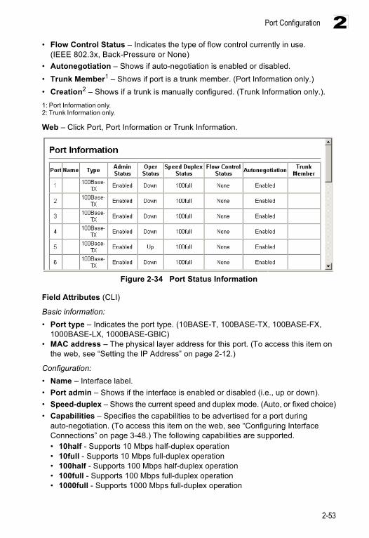
Port Configuration
2-53
2• Flow Control Status – Indicates the type of flow control currently in use.
(IEEE 802.3x, Back-Pressure or None)• Autonegotiation – Shows if auto-negotiation is enabled or disabled.• Trunk Member1 – Shows if port is a trunk member. (Port Information only.)• Creation2 – Shows if a trunk is manually configured. (Trunk Information only.).1: Port Information only.2: Trunk Information only.
Web – Click Port, Port Information or Trunk Information.
Figure 2-34 Port Status Information
Field Attributes (CLI)
Basic information:• Port type – Indicates the port type. (10BASE-T, 100BASE-TX, 100BASE-FX,
1000BASE-LX, 1000BASE-GBIC)• MAC address – The physical layer address for this port. (To access this item on
the web, see “Setting the IP Address” on page 2-12.)
Configuration:• Name – Interface label.• Port admin – Shows if the interface is enabled or disabled (i.e., up or down).• Speed-duplex – Shows the current speed and duplex mode. (Auto, or fixed choice)• Capabilities – Specifies the capabilities to be advertised for a port during
auto-negotiation. (To access this item on the web, see “Configuring Interface Connections” on page 3-48.) The following capabilities are supported. • 10half - Supports 10 Mbps half-duplex operation • 10full - Supports 10 Mbps full-duplex operation • 100half - Supports 100 Mbps half-duplex operation • 100full - Supports 100 Mbps full-duplex operation • 1000full - Supports 1000 Mbps full-duplex operation
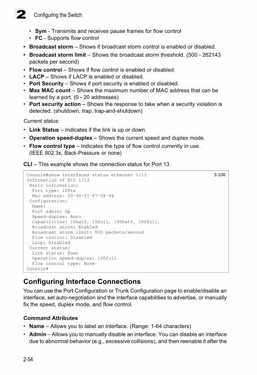
Configuring the Switch
2-54
2• Sym - Transmits and receives pause frames for flow control• FC - Supports flow control
• Broadcast storm – Shows if broadcast storm control is enabled or disabled.• Broadcast storm limit – Shows the broadcast storm threshold. (500 - 262143
packets per second)• Flow control – Shows if flow control is enabled or disabled.• LACP – Shows if LACP is enabled or disabled.• Port Security – Shows if port security is enabled or disabled.• Max MAC count – Shows the maximum number of MAC address that can be
learned by a port. (0 - 20 addresses)• Port security action – Shows the response to take when a security violation is
detected. (shutdown, trap, trap-and-shutdown)
Current status:• Link Status – Indicates if the link is up or down.• Operation speed-duplex – Shows the current speed and duplex mode.• Flow control type – Indicates the type of flow control currently in use.
(IEEE 802.3x, Back-Pressure or none)
CLI – This example shows the connection status for Port 13.
Configuring Interface ConnectionsYou can use the Port Configuration or Trunk Configuration page to enable/disable an interface, set auto-negotiation and the interface capabilities to advertise, or manually fix the speed, duplex mode, and flow control.
Command Attributes• Name – Allows you to label an interface. (Range: 1-64 characters)• Admin – Allows you to manually disable an interface. You can disable an interface
due to abnormal behavior (e.g., excessive collisions), and then reenable it after the
Console#show interfaces status ethernet 1/13 3-106Information of Eth 1/13 Basic information: Port type: 100tx Mac address: 00-30-f1-47-58-46 Configuration: Name: Port admin: Up Speed-duplex: Auto Capabilities: 10half, 10full, 100half, 100full, Broadcast storm: Enabled Broadcast storm limit: 500 packets/second Flow control: Disabled Lacp: Disabled Current status: Link status: Down Operation speed-duplex: 100full Flow control type: NoneConsole#
Port Configuration
2-55
2problem has been resolved. You may also disable an interface for security reasons.
• Speed/Duplex – Allows manual selection of port speed and duplex mode (i.e., with auto-negotiation disabled).
• Flow Control – Allows automatic or manual selection of flow control.• Autonegotiation (Port Capabilities) – Allows auto-negotiation to be enabled/
disabled. When auto-negotiation is enabled, you need to specify the capabilities to be advertised. When auto-negotiation is disabled, you can force the settings for speed, mode, and flow control.The following capabilities are supported. - 10half - Supports 10 Mbps half-duplex operation- 10full - Supports 10 Mbps full-duplex operation - 100half - Supports 100 Mbps half-duplex operation - 100full - Supports 100 Mbps full-duplex operation - 1000full - Supports 1000 Mbps full-duplex operation - Sym (Gigabit only) - When specified, the port transmits and receives pause
frames; when not specified, the port will auto-negotiate to determine the sender and receiver for asymmetric pause frames. (The current switch chip only supports symmetric pause frames.)
- FC - Supports flow control Flow control can eliminate frame loss by “blocking” traffic from end stations or segments connected directly to the switch when its buffers fill. When enabled, back pressure is used for half-duplex operation and IEEE 802.3x for full-duplex operation. (Avoid using flow control on a port connected to a hub unless it is actually required to solve a problem. Otherwise back pressure jamming signals may degrade overall performance for the segment attached to the hub.)
(Default: Autonegotiation enabled; Advertised capabilities for 100BASE-TX – 10half, 10full, 100half, 100full; 1000BASE-T – 10half, 10full, 100half, 100full, 1000full; 1000BASE-LX – 1000full)
• Trunk – Indicates if a port is a member of a trunk. To create trunks and select port members, see “Trunk Configuration” on page 2-56.
Note: Autonegotiation must be disabled before you can configure or force the interface to use the Speed/Duplex Mode or Flow Control options.
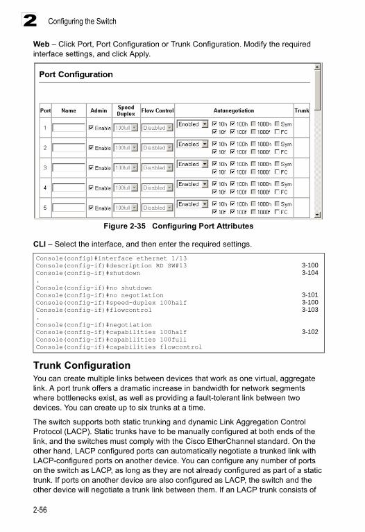
Configuring the Switch
2-56
2Web – Click Port, Port Configuration or Trunk Configuration. Modify the required interface settings, and click Apply.
Figure 2-35 Configuring Port Attributes
CLI – Select the interface, and then enter the required settings.
Trunk ConfigurationYou can create multiple links between devices that work as one virtual, aggregate link. A port trunk offers a dramatic increase in bandwidth for network segments where bottlenecks exist, as well as providing a fault-tolerant link between two devices. You can create up to six trunks at a time.
The switch supports both static trunking and dynamic Link Aggregation Control Protocol (LACP). Static trunks have to be manually configured at both ends of the link, and the switches must comply with the Cisco EtherChannel standard. On the other hand, LACP configured ports can automatically negotiate a trunked link with LACP-configured ports on another device. You can configure any number of ports on the switch as LACP, as long as they are not already configured as part of a static trunk. If ports on another device are also configured as LACP, the switch and the other device will negotiate a trunk link between them. If an LACP trunk consists of
Console(config)#interface ethernet 1/13Console(config-if)#description RD SW#13 3-100Console(config-if)#shutdown 3-104.Console(config-if)#no shutdownConsole(config-if)#no negotiation 3-101Console(config-if)#speed-duplex 100half 3-100Console(config-if)#flowcontrol 3-103.Console(config-if)#negotiationConsole(config-if)#capabilities 100half 3-102Console(config-if)#capabilities 100full Console(config-if)#capabilities flowcontrol
Port Configuration
2-57
2more than four ports, all other ports will be placed in a standby mode. Should one link in the trunk fail, one of the standby ports will automatically be activated to replace it.
Command UsageBesides balancing the load across each port in the trunk, the other ports provide redundancy by taking over the load if a port in the trunk fails. However, before making any physical connections between devices, use the Web interface or CLI to specify the trunk on the devices at both ends. When using a port trunk, take note of the following points:
• Finish configuring port trunks before you connect the corresponding network cables between switches to avoid creating a loop.
• You can create up to six trunks on the switch, with up to four ports per trunk.• The ports at both ends of a connection must be configured as trunk ports.• When configuring static trunks on switches of different types, they must be
compatible with the Cisco EtherChannel standard.• When configuring static trunks, you may not be able to link switches of different
types, depending on the manufacturer's implementation.• The ports at both ends of a trunk must be configured in an identical manner,
including communication mode (i.e., speed, duplex mode and flow control), VLAN assignments, and CoS settings.
• All the ports in a trunk have to be treated as a whole when moved from/to, added or deleted from a VLAN.
• STP, VLAN, and IGMP settings can only be made for the entire trunk.
Statically Configuring a TrunkCommand Usage• When configuring static trunks, you may not be able to link switches of different
types, depending on the manufacturer’s implementation. However, note that the static trunks on this switch are Cisco EtherChannel compatible.
• To avoid creating a loop in the network, be sure you add a static trunk via the configuration interface before connecting the ports, and also disconnect the ports before removing a static trunk via the configuration interface.
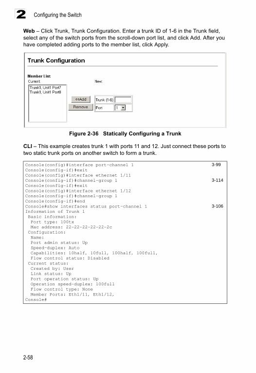
Configuring the Switch
2-58
2Web – Click Trunk, Trunk Configuration. Enter a trunk ID of 1-6 in the Trunk field, select any of the switch ports from the scroll-down port list, and click Add. After you have completed adding ports to the member list, click Apply.
Figure 2-36 Statically Configuring a Trunk
CLI – This example creates trunk 1 with ports 11 and 12. Just connect these ports to two static trunk ports on another switch to form a trunk.
Console(config)#interface port-channel 1 3-99Console(config-if)#exitConsole(config)#interface ethernet 1/11Console(config-if)#channel-group 1 3-114Console(config-if)#exitConsole(config)#interface ethernet 1/12Console(config-if)#channel-group 1Console(config-if)#endConsole#show interfaces status port-channel 1 3-106Information of Trunk 1 Basic information: Port type: 100tx Mac address: 22-22-22-22-22-2c Configuration: Name: Port admin status: Up Speed-duplex: Auto Capabilities: 10half, 10full, 100half, 100full, Flow control status: Disabled Current status: Created by: User Link status: Up Port operation status: Up Operation speed-duplex: 100full Flow control type: None Member Ports: Eth1/11, Eth1/12,Console#
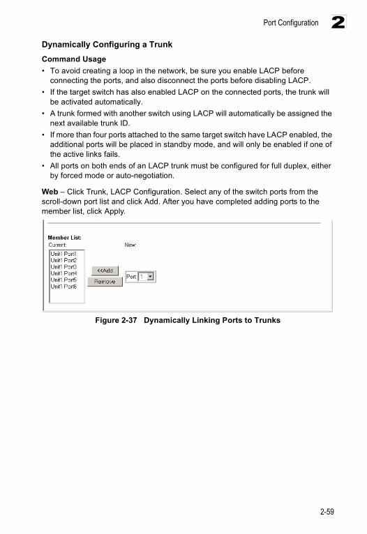
Port Configuration
2-59
2Dynamically Configuring a TrunkCommand Usage• To avoid creating a loop in the network, be sure you enable LACP before
connecting the ports, and also disconnect the ports before disabling LACP. • If the target switch has also enabled LACP on the connected ports, the trunk will
be activated automatically. • A trunk formed with another switch using LACP will automatically be assigned the
next available trunk ID. • If more than four ports attached to the same target switch have LACP enabled, the
additional ports will be placed in standby mode, and will only be enabled if one of the active links fails.
• All ports on both ends of an LACP trunk must be configured for full duplex, either by forced mode or auto-negotiation.
Web – Click Trunk, LACP Configuration. Select any of the switch ports from the scroll-down port list and click Add. After you have completed adding ports to the member list, click Apply.
Figure 2-37 Dynamically Linking Ports to Trunks
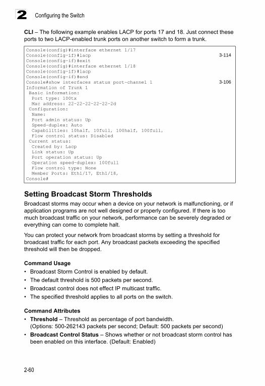
Configuring the Switch
2-60
2CLI – The following example enables LACP for ports 17 and 18. Just connect these ports to two LACP-enabled trunk ports on another switch to form a trunk.
Setting Broadcast Storm ThresholdsBroadcast storms may occur when a device on your network is malfunctioning, or if application programs are not well designed or properly configured. If there is too much broadcast traffic on your network, performance can be severely degraded or everything can come to complete halt.
You can protect your network from broadcast storms by setting a threshold for broadcast traffic for each port. Any broadcast packets exceeding the specified threshold will then be dropped.
Command Usage• Broadcast Storm Control is enabled by default.• The default threshold is 500 packets per second.• Broadcast control does not effect IP multicast traffic.• The specified threshold applies to all ports on the switch.
Command Attributes• Threshold – Threshold as percentage of port bandwidth.
(Options: 500-262143 packets per second; Default: 500 packets per second) • Broadcast Control Status – Shows whether or not broadcast storm control has
been enabled on this interface. (Default: Enabled)
Console(config)#interface ethernet 1/17Console(config-if)#lacp 3-114Console(config-if)#exitConsole(config)#interface ethernet 1/18Console(config-if)#lacpConsole(config-if)#endConsole#show interfaces status port-channel 1 3-106Information of Trunk 1 Basic information: Port type: 100tx Mac address: 22-22-22-22-22-2d Configuration: Name: Port admin status: Up Speed-duplex: Auto Capabilities: 10half, 10full, 100half, 100full, Flow control status: Disabled Current status: Created by: Lacp Link status: Up Port operation status: Up Operation speed-duplex: 100full Flow control type: None Member Ports: Eth1/17, Eth1/18,Console#
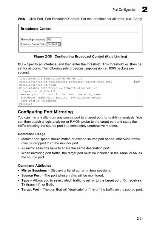
Port Configuration
2-61
2Web – Click Port, Port Broadcast Control. Set the threshold for all ports, click Apply.
Figure 2-38 Configuring Broadcast Control (Rate Limiting)
CLI – Specify an interface, and then enter the threshold. This threshold will then be set for all ports. The following sets broadcast suppression at 1000 packets per second.
Configuring Port MirroringYou can mirror traffic from any source port to a target port for real-time analysis. You can then attach a logic analyzer or RMON probe to the target port and study the traffic crossing the source port in a completely unobtrusive manner.
Command Usage• Monitor port speed should match or exceed source port speed, otherwise traffic
may be dropped from the monitor port.• All mirror sessions have to share the same destination port. • When mirroring port traffic, the target port must be included in the same VLAN as
the source port.
Command Attributes• Mirror Sessions – Displays a list of current mirror sessions.• Source Port – The port whose traffic will be monitored.• Type – Allows you to select which traffic to mirror to the target port, Rx (receive),
Tx (transmit), or Both.• Target Port – The port that will “duplicate” or “mirror” the traffic on the source port.
Console(config)#interface ethernet 1/1Console(config-if)#switchport broadcast packet-rate 1000 3-104Console(config-if)#endConsole#show interfaces switchport ethernet 1/2Information of Eth 1/2 Member port of trunk 1, that was created by user. Broadcast threshold: Enabled, 600 packets/second Lacp status: DisabledConsole#
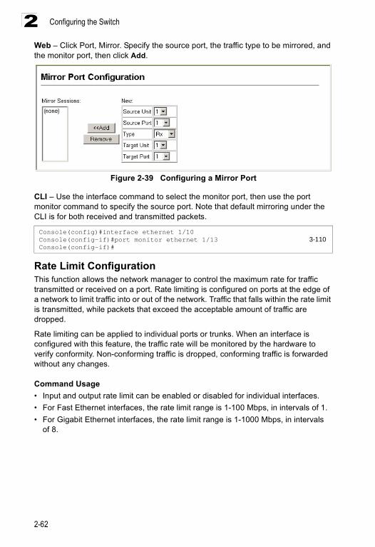
Configuring the Switch
2-62
2Web – Click Port, Mirror. Specify the source port, the traffic type to be mirrored, and the monitor port, then click Add.
Figure 2-39 Configuring a Mirror Port
CLI – Use the interface command to select the monitor port, then use the port monitor command to specify the source port. Note that default mirroring under the CLI is for both received and transmitted packets.
Rate Limit ConfigurationThis function allows the network manager to control the maximum rate for traffic transmitted or received on a port. Rate limiting is configured on ports at the edge of a network to limit traffic into or out of the network. Traffic that falls within the rate limit is transmitted, while packets that exceed the acceptable amount of traffic are dropped.
Rate limiting can be applied to individual ports or trunks. When an interface is configured with this feature, the traffic rate will be monitored by the hardware to verify conformity. Non-conforming traffic is dropped, conforming traffic is forwarded without any changes.
Command Usage• Input and output rate limit can be enabled or disabled for individual interfaces.• For Fast Ethernet interfaces, the rate limit range is 1-100 Mbps, in intervals of 1.• For Gigabit Ethernet interfaces, the rate limit range is 1-1000 Mbps, in intervals
of 8.
Console(config)#interface ethernet 1/10Console(config-if)#port monitor ethernet 1/13 3-110Console(config-if)#
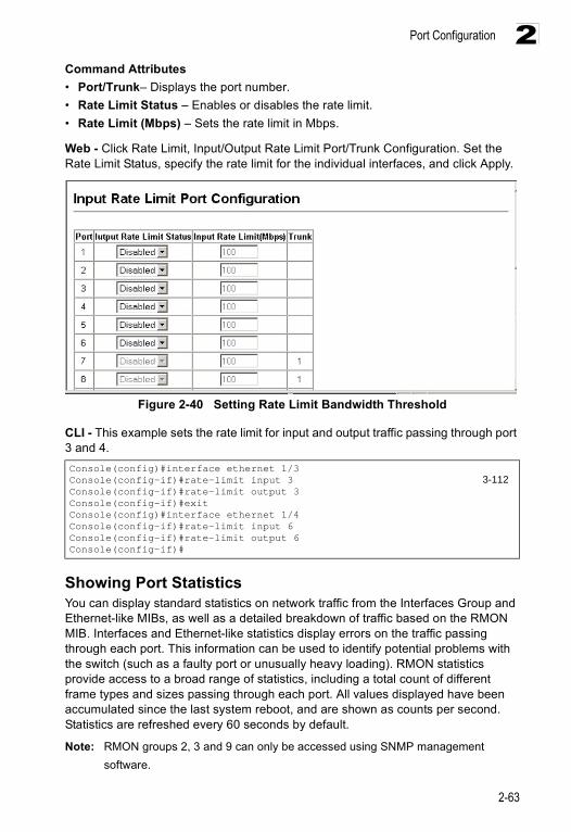
Port Configuration
2-63
2Command Attributes• Port/Trunk– Displays the port number.• Rate Limit Status – Enables or disables the rate limit.• Rate Limit (Mbps) – Sets the rate limit in Mbps.
Web - Click Rate Limit, Input/Output Rate Limit Port/Trunk Configuration. Set the Rate Limit Status, specify the rate limit for the individual interfaces, and click Apply.
Figure 2-40 Setting Rate Limit Bandwidth Threshold
CLI - This example sets the rate limit for input and output traffic passing through port 3 and 4.
Showing Port StatisticsYou can display standard statistics on network traffic from the Interfaces Group and Ethernet-like MIBs, as well as a detailed breakdown of traffic based on the RMON MIB. Interfaces and Ethernet-like statistics display errors on the traffic passing through each port. This information can be used to identify potential problems with the switch (such as a faulty port or unusually heavy loading). RMON statistics provide access to a broad range of statistics, including a total count of different frame types and sizes passing through each port. All values displayed have been accumulated since the last system reboot, and are shown as counts per second. Statistics are refreshed every 60 seconds by default.
Note: RMON groups 2, 3 and 9 can only be accessed using SNMP management software.
Console(config)#interface ethernet 1/3 Console(config-if)#rate-limit input 3 3-112Console(config-if)#rate-limit output 3Console(config-if)#exitConsole(config)#interface ethernet 1/4Console(config-if)#rate-limit input 6Console(config-if)#rate-limit output 6Console(config-if)#
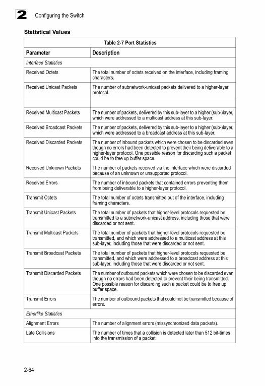
Configuring the Switch
2-64
2Statistical Values
Table 2-7 Port Statistics
Parameter DescriptionInterface Statistics
Received Octets The total number of octets received on the interface, including framing characters.
Received Unicast Packets The number of subnetwork-unicast packets delivered to a higher-layer protocol.
Received Multicast Packets The number of packets, delivered by this sub-layer to a higher (sub-)layer, which were addressed to a multicast address at this sub-layer.
Received Broadcast Packets The number of packets, delivered by this sub-layer to a higher (sub-)layer, which were addressed to a broadcast address at this sub-layer.
Received Discarded Packets The number of inbound packets which were chosen to be discarded even though no errors had been detected to prevent their being deliverable to a higher-layer protocol. One possible reason for discarding such a packet could be to free up buffer space.
Received Unknown Packets The number of packets received via the interface which were discarded because of an unknown or unsupported protocol.
Received Errors The number of inbound packets that contained errors preventing them from being deliverable to a higher-layer protocol.
Transmit Octets The total number of octets transmitted out of the interface, including framing characters.
Transmit Unicast Packets The total number of packets that higher-level protocols requested be transmitted to a subnetwork-unicast address, including those that were discarded or not sent.
Transmit Multicast Packets The total number of packets that higher-level protocols requested be transmitted, and which were addressed to a multicast address at this sub-layer, including those that were discarded or not sent.
Transmit Broadcast Packets The total number of packets that higher-level protocols requested be transmitted, and which were addressed to a broadcast address at this sub-layer, including those that were discarded or not sent.
Transmit Discarded Packets The number of outbound packets which were chosen to be discarded even though no errors had been detected to prevent their being transmitted. One possible reason for discarding such a packet could be to free up buffer space.
Transmit Errors The number of outbound packets that could not be transmitted because of errors.
Etherlike Statistics
Alignment Errors The number of alignment errors (missynchronized data packets).
Late Collisions The number of times that a collision is detected later than 512 bit-times into the transmission of a packet.
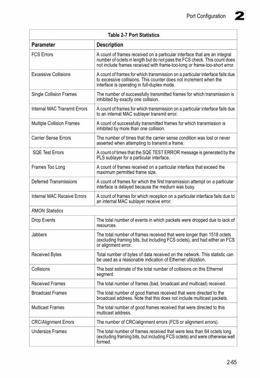
Port Configuration
2-65
2
FCS Errors A count of frames received on a particular interface that are an integral number of octets in length but do not pass the FCS check. This count does not include frames received with frame-too-long or frame-too-short error.
Excessive Collisions A count of frames for which transmission on a particular interface fails due to excessive collisions. This counter does not increment when the interface is operating in full-duplex mode.
Single Collision Frames The number of successfully transmitted frames for which transmission is inhibited by exactly one collision.
Internal MAC Transmit Errors A count of frames for which transmission on a particular interface fails due to an internal MAC sublayer transmit error.
Multiple Collision Frames A count of successfully transmitted frames for which transmission is inhibited by more than one collision.
Carrier Sense Errors The number of times that the carrier sense condition was lost or never asserted when attempting to transmit a frame.
SQE Test Errors A count of times that the SQE TEST ERROR message is generated by the PLS sublayer for a particular interface.
Frames Too Long A count of frames received on a particular interface that exceed the maximum permitted frame size.
Deferred Transmissions A count of frames for which the first transmission attempt on a particular interface is delayed because the medium was busy.
Internal MAC Receive Errors A count of frames for which reception on a particular interface fails due to an internal MAC sublayer receive error.
RMON Statistics
Drop Events The total number of events in which packets were dropped due to lack of resources.
Jabbers The total number of frames received that were longer than 1518 octets (excluding framing bits, but including FCS octets), and had either an FCS or alignment error.
Received Bytes Total number of bytes of data received on the network. This statistic can be used as a reasonable indication of Ethernet utilization.
Collisions The best estimate of the total number of collisions on this Ethernet segment.
Received Frames The total number of frames (bad, broadcast and multicast) received.
Broadcast Frames The total number of good frames received that were directed to the broadcast address. Note that this does not include multicast packets.
Multicast Frames The total number of good frames received that were directed to this multicast address.
CRC/Alignment Errors The number of CRC/alignment errors (FCS or alignment errors).
Undersize Frames The total number of frames received that were less than 64 octets long (excluding framing bits, but including FCS octets) and were otherwise well formed.
Table 2-7 Port Statistics
Parameter Description
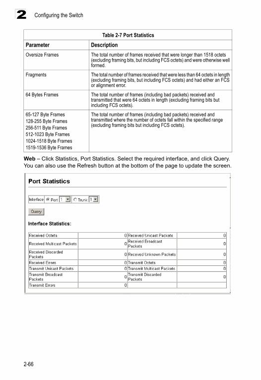
Configuring the Switch
2-66
2
Web – Click Statistics, Port Statistics. Select the required interface, and click Query. You can also use the Refresh button at the bottom of the page to update the screen.
Oversize Frames The total number of frames received that were longer than 1518 octets (excluding framing bits, but including FCS octets) and were otherwise well formed.
Fragments The total number of frames received that were less than 64 octets in length (excluding framing bits, but including FCS octets) and had either an FCS or alignment error.
64 Bytes Frames The total number of frames (including bad packets) received and transmitted that were 64 octets in length (excluding framing bits but including FCS octets).
65-127 Byte Frames128-255 Byte Frames256-511 Byte Frames512-1023 Byte Frames1024-1518 Byte Frames1519-1536 Byte Frames
The total number of frames (including bad packets) received and transmitted where the number of octets fall within the specified range (excluding framing bits but including FCS octets).
Table 2-7 Port Statistics
Parameter Description
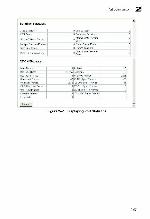
Port Configuration
2-67
2
Figure 2-41 Displaying Port Statistics
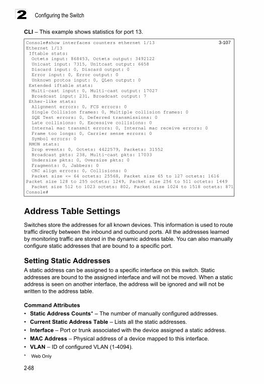
Configuring the Switch
2-68
2CLI – This example shows statistics for port 13.
Address Table SettingsSwitches store the addresses for all known devices. This information is used to route traffic directly between the inbound and outbound ports. All the addresses learned by monitoring traffic are stored in the dynamic address table. You can also manually configure static addresses that are bound to a specific port.
Setting Static AddressesA static address can be assigned to a specific interface on this switch. Static addresses are bound to the assigned interface and will not be moved. When a static address is seen on another interface, the address will be ignored and will not be written to the address table.
Command Attributes• Static Address Counts* – The number of manually configured addresses.• Current Static Address Table – Lists all the static addresses.• Interface – Port or trunk associated with the device assigned a static address.• MAC Address – Physical address of a device mapped to this interface.• VLAN – ID of configured VLAN (1-4094). * Web Only
Console#show interfaces counters ethernet 1/13 3-107Ethernet 1/13 Iftable stats: Octets input: 868453, Octets output: 3492122 Unicast input: 7315, Unitcast output: 6658 Discard input: 0, Discard output: 0 Error input: 0, Error output: 0 Unknown protos input: 0, QLen output: 0 Extended iftable stats: Multi-cast input: 0, Multi-cast output: 17027 Broadcast input: 231, Broadcast output: 7 Ether-like stats: Alignment errors: 0, FCS errors: 0 Single Collision frames: 0, Multiple collision frames: 0 SQE Test errors: 0, Deferred transmissions: 0 Late collisions: 0, Excessive collisions: 0 Internal mac transmit errors: 0, Internal mac receive errors: 0 Frame too longs: 0, Carrier sense errors: 0 Symbol errors: 0 RMON stats: Drop events: 0, Octets: 4422579, Packets: 31552 Broadcast pkts: 238, Multi-cast pkts: 17033 Undersize pkts: 0, Oversize pkts: 0 Fragments: 0, Jabbers: 0 CRC align errors: 0, Collisions: 0 Packet size <= 64 octets: 25568, Packet size 65 to 127 octets: 1616Packet size 128 to 255 octets: 1249, Packet size 256 to 511 octets: 1449 Packet size 512 to 1023 octets: 802, Packet size 1024 to 1518 octets: 871Console#
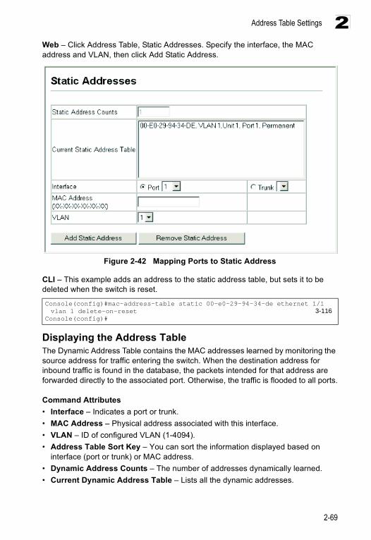
Address Table Settings
2-69
2Web – Click Address Table, Static Addresses. Specify the interface, the MAC address and VLAN, then click Add Static Address.
Figure 2-42 Mapping Ports to Static Address
CLI – This example adds an address to the static address table, but sets it to be deleted when the switch is reset.
Displaying the Address TableThe Dynamic Address Table contains the MAC addresses learned by monitoring the source address for traffic entering the switch. When the destination address for inbound traffic is found in the database, the packets intended for that address are forwarded directly to the associated port. Otherwise, the traffic is flooded to all ports.
Command Attributes• Interface – Indicates a port or trunk.• MAC Address – Physical address associated with this interface.• VLAN – ID of configured VLAN (1-4094).• Address Table Sort Key – You can sort the information displayed based on
interface (port or trunk) or MAC address.• Dynamic Address Counts – The number of addresses dynamically learned.• Current Dynamic Address Table – Lists all the dynamic addresses.
Console(config)#mac-address-table static 00-e0-29-94-34-de ethernet 1/1 vlan 1 delete-on-reset 3-116
Console(config)#
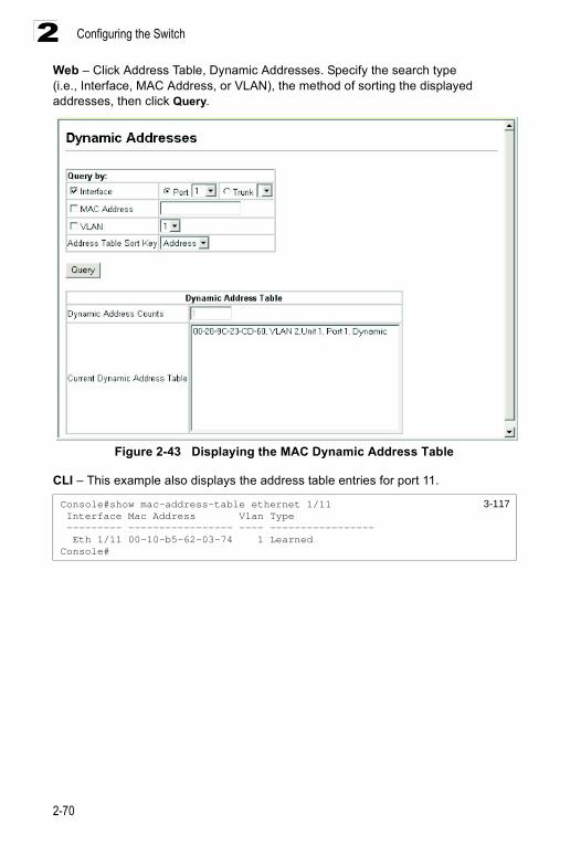
Configuring the Switch
2-70
2Web – Click Address Table, Dynamic Addresses. Specify the search type (i.e., Interface, MAC Address, or VLAN), the method of sorting the displayed addresses, then click Query.
Figure 2-43 Displaying the MAC Dynamic Address Table
CLI – This example also displays the address table entries for port 11.
Console#show mac-address-table ethernet 1/11 3-117 Interface Mac Address Vlan Type --------- ----------------- ---- ----------------- Eth 1/11 00-10-b5-62-03-74 1 LearnedConsole#
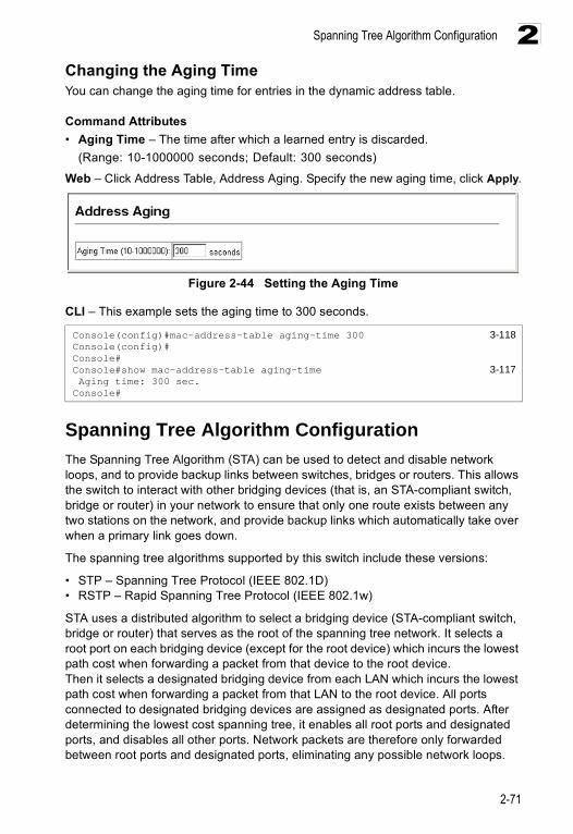
Spanning Tree Algorithm Configuration
2-71
2Changing the Aging TimeYou can change the aging time for entries in the dynamic address table.
Command Attributes• Aging Time – The time after which a learned entry is discarded.
(Range: 10-1000000 seconds; Default: 300 seconds)
Web – Click Address Table, Address Aging. Specify the new aging time, click Apply.
Figure 2-44 Setting the Aging Time
CLI – This example sets the aging time to 300 seconds.
Spanning Tree Algorithm ConfigurationThe Spanning Tree Algorithm (STA) can be used to detect and disable network loops, and to provide backup links between switches, bridges or routers. This allows the switch to interact with other bridging devices (that is, an STA-compliant switch, bridge or router) in your network to ensure that only one route exists between any two stations on the network, and provide backup links which automatically take over when a primary link goes down.
The spanning tree algorithms supported by this switch include these versions:
• STP – Spanning Tree Protocol (IEEE 802.1D)• RSTP – Rapid Spanning Tree Protocol (IEEE 802.1w)
STA uses a distributed algorithm to select a bridging device (STA-compliant switch, bridge or router) that serves as the root of the spanning tree network. It selects a root port on each bridging device (except for the root device) which incurs the lowest path cost when forwarding a packet from that device to the root device.Then it selects a designated bridging device from each LAN which incurs the lowest path cost when forwarding a packet from that LAN to the root device. All ports connected to designated bridging devices are assigned as designated ports. After determining the lowest cost spanning tree, it enables all root ports and designated ports, and disables all other ports. Network packets are therefore only forwarded between root ports and designated ports, eliminating any possible network loops.
Console(config)#mac-address-table aging-time 300 3-118Console(config)#Console#Console#show mac-address-table aging-time 3-117 Aging time: 300 sec.Console#
Configuring the Switch
2-72
2Once a stable network topology has been established, all bridges listen for Hello BPDUs (Bridge Protocol Data Units) transmitted from the Root Bridge. If a bridge does not get a Hello BPDU after a predefined interval (Maximum Age), the bridge assumes that the link to the Root Bridge is down. This bridge will then initiate negotiations with other bridges to reconfigure the network to reestablish a valid network topology.
RSTP is designed as a general replacement for the slower, legacy STP. RSTP achieves must faster reconfiguration (i.e., around one tenth of the time required by STP) by reducing the number of state changes before active ports start learning, predefining an alternate route that can be used when a node or port fails, and retaining the forwarding database for ports insensitive to changes in the tree structure when reconfiguration occurs.
Displaying Global Settings
Field Attributes• Spanning Tree State – Shows if the switch is enabled to participate in an
STA-compliant network.• Bridge ID – A unique identifier for this bridge, consisting of the bridge priority and
MAC address (where the address is taken from the switch system).• Max Age – The maximum time (in seconds) a device can wait without receiving a
configuration message before attempting to reconfigure. All device ports (except for designated ports) should receive configuration messages at regular intervals. Any port that ages out STA information (provided in the last configuration message) becomes the designated port for the attached LAN. If it is a root port, a new root port is selected from among the device ports attached to the network. (References to “ports” in this section mean “interfaces,” which includes both ports and trunks.)
• Hello Time – Interval (in seconds) at which the root device transmits a configuration message.
• Forward Delay – The maximum time (in seconds) the root device will wait before changing states (i.e., discarding to learning to forwarding). This delay is required because every device must receive information about topology changes before it starts to forward frames. In addition, each port needs time to listen for conflicting information that would make it return to a discarding state; otherwise, temporary data loops might result.
• Designated Root – The priority and MAC address of the device in the Spanning Tree that this switch has accepted as the root device.- Root Port – The number of the port on this switch that is closest to the root. This
switch communicates with the root device through this port. If there is no root port, then this switch has been accepted as the root device of the Spanning Tree network.
- Root Path Cost – The path cost from the root port on this switch to the root device.
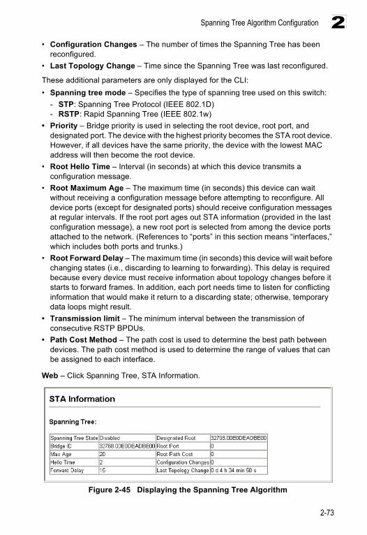
Spanning Tree Algorithm Configuration
2-73
2• Configuration Changes – The number of times the Spanning Tree has been
reconfigured.• Last Topology Change – Time since the Spanning Tree was last reconfigured.
These additional parameters are only displayed for the CLI:• Spanning tree mode – Specifies the type of spanning tree used on this switch:
- STP: Spanning Tree Protocol (IEEE 802.1D)- RSTP: Rapid Spanning Tree (IEEE 802.1w)
• Priority – Bridge priority is used in selecting the root device, root port, and designated port. The device with the highest priority becomes the STA root device. However, if all devices have the same priority, the device with the lowest MAC address will then become the root device.
• Root Hello Time – Interval (in seconds) at which this device transmits a configuration message.
• Root Maximum Age – The maximum time (in seconds) this device can wait without receiving a configuration message before attempting to reconfigure. All device ports (except for designated ports) should receive configuration messages at regular intervals. If the root port ages out STA information (provided in the last configuration message), a new root port is selected from among the device ports attached to the network. (References to “ports” in this section means “interfaces,” which includes both ports and trunks.)
• Root Forward Delay – The maximum time (in seconds) this device will wait before changing states (i.e., discarding to learning to forwarding). This delay is required because every device must receive information about topology changes before it starts to forward frames. In addition, each port needs time to listen for conflicting information that would make it return to a discarding state; otherwise, temporary data loops might result.
• Transmission limit – The minimum interval between the transmission of consecutive RSTP BPDUs.
• Path Cost Method – The path cost is used to determine the best path between devices. The path cost method is used to determine the range of values that can be assigned to each interface.
Web – Click Spanning Tree, STA Information.
Figure 2-45 Displaying the Spanning Tree Algorithm
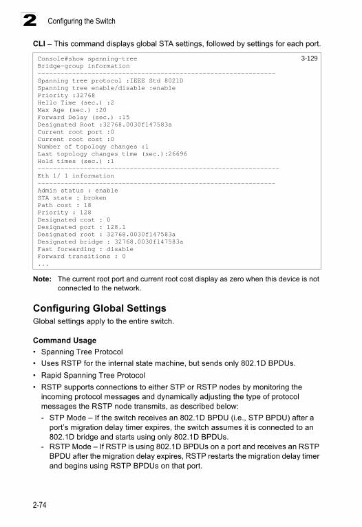
Configuring the Switch
2-74
2CLI – This command displays global STA settings, followed by settings for each port.
Note: The current root port and current root cost display as zero when this device is not connected to the network.
Configuring Global SettingsGlobal settings apply to the entire switch.
Command Usage• Spanning Tree Protocol• Uses RSTP for the internal state machine, but sends only 802.1D BPDUs.• Rapid Spanning Tree Protocol• RSTP supports connections to either STP or RSTP nodes by monitoring the
incoming protocol messages and dynamically adjusting the type of protocol messages the RSTP node transmits, as described below:- STP Mode – If the switch receives an 802.1D BPDU (i.e., STP BPDU) after a
port’s migration delay timer expires, the switch assumes it is connected to an 802.1D bridge and starts using only 802.1D BPDUs.
- RSTP Mode – If RSTP is using 802.1D BPDUs on a port and receives an RSTP BPDU after the migration delay expires, RSTP restarts the migration delay timer and begins using RSTP BPDUs on that port.
Console#show spanning-tree 3-129Bridge-group information--------------------------------------------------------------Spanning tree protocol :IEEE Std 8021DSpanning tree enable/disable :enablePriority :32768Hello Time (sec.) :2Max Age (sec.) :20Forward Delay (sec.) :15Designated Root :32768.0030f147583aCurrent root port :0Current root cost :0Number of topology changes :1Last topology changes time (sec.):26696Hold times (sec.) :1---------------------------------------------------------------Eth 1/ 1 information--------------------------------------------------------------Admin status : enableSTA state : brokenPath cost : 18Priority : 128Designated cost : 0Designated port : 128.1Designated root : 32768.0030f147583aDesignated bridge : 32768.0030f147583aFast forwarding : disableForward transitions : 0...
Spanning Tree Algorithm Configuration
2-75
2Command Attributes
Basic Configuration of Global Settings• Spanning Tree State – Enables/disables STA on this switch. (Default: Enabled)• Spanning Tree Type – Specifies the type of spanning tree used on this switch:
- STP: Spanning Tree Protocol (IEEE 802.1D; i.e., when this option is selected, the switch will use RSTP set to STP forced compatibility mode)
- RSTP: Rapid Spanning Tree (IEEE 802.1w) RSTP is the default.• Priority – Bridge priority is used in selecting the root device, root port, and
designated port. The device with the highest priority becomes the STA root device. However, if all devices have the same priority, the device with the lowest MAC address will then become the root device. - Default: 32768- Range: 0-61440, in steps of 4096- Options: 0, 4096, 8192, 12288, 16384, 20480, 24576, 28672, 32768, 36864,
40960, 45056, 49152, 53248, 57344, 61440
Root Device Configuration• Hello Time – Interval (in seconds) at which this device transmits a configuration
message. - Default: 2- Minimum: 1 - Maximum: The lower of 10 or [(Max. Message Age / 2) -1]
• Maximum Age – The maximum time (in seconds) a device can wait without receiving a configuration message before attempting to reconfigure. All device ports (except for designated ports) should receive configuration messages at regular intervals. Any port that ages out STA information (provided in the last configuration message) becomes the designated port for the attached LAN. If it is a root port, a new root port is selected from among the device ports attached to the network. (References to “ports” in this section mean “interfaces,” which includes both ports and trunks.)• Default: 20• Minimum: The higher of 6 or [2 x (Hello Time + 1)].• Maximum: The lower of 40 or [2 x (Forward Delay - 1)]
• Forward Delay – The maximum time (in seconds) this device will wait before changing states (i.e., discarding to learning to forwarding). This delay is required because every device must receive information about topology changes before it starts to forward frames. In addition, each port needs time to listen for conflicting information that would make it return to a discarding state; otherwise, temporary data loops might result.- Default: 15- Minimum: The higher of 4 or [(Max. Message Age / 2) + 1]- Maximum: 30
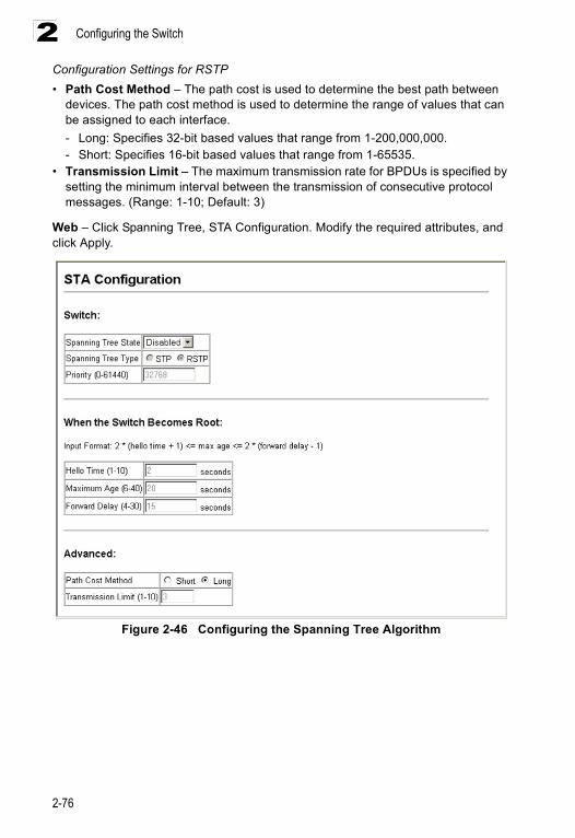
Configuring the Switch
2-76
2Configuration Settings for RSTP • Path Cost Method – The path cost is used to determine the best path between
devices. The path cost method is used to determine the range of values that can be assigned to each interface. - Long: Specifies 32-bit based values that range from 1-200,000,000.- Short: Specifies 16-bit based values that range from 1-65535.
• Transmission Limit – The maximum transmission rate for BPDUs is specified by setting the minimum interval between the transmission of consecutive protocol messages. (Range: 1-10; Default: 3)
Web – Click Spanning Tree, STA Configuration. Modify the required attributes, and click Apply.
Figure 2-46 Configuring the Spanning Tree Algorithm
Spanning Tree Algorithm Configuration
2-77
2CLI – This example enables Spanning Tree Protocol, and then sets the indicated attributes.
Displaying Interface Settings The STP Port Information and STP Trunk Information pages display the current status of ports and trunks in the Spanning Tree.
Command AttributesThe following attributes are read-only and cannot be changed:
• STA Status – Displays current state of this port within the Spanning Tree:- Discarding - Port receives STA configuration messages, but does not forward
packets.- Learning - Port has transmitted configuration messages for an interval set by
the Forward Delay parameter without receiving contradictory information. Port address table is cleared, and the port begins learning addresses.
- Forwarding - Port forwards packets, and continues learning addresses.
The rules defining port status are:• A port on a network segment with no other STA compliant bridging device is
always forwarding.
• If two ports of a switch are connected to the same segment and there is no other STA device attached to this segment, the port with the smaller ID forwards packets and the other is discarding.
• All ports are discarding when the switch is booted, then some of them change state to learning, and then to forwarding.
• Forward Transitions – The number of times this port has changed from the Learning state to the Forwarding state.
• Designated Cost – The cost for a packet to travel from this port to the root in the current Spanning Tree configuration. The slower the media, the higher the cost.
• Designated Bridge – The bridge priority and MAC address of the device through which this port must communicate to reach the root of the Spanning Tree.
• Designated Port – The port priority and number of the port on the designated bridging device through which this switch must communicate with the root of the Spanning Tree.
Console(config)#spanning-tree 3-119Console(config)#spanning-tree mode 3-120Console(config)#spanning-tree priority 40000 3-123Console(config)#spanning-tree hello-time 5 3-121Console(config)#spanning-tree max-age 38 3-122Console(config)#spanning-tree forward-time 20 3-121Console(config)#spanning-tree pathcost method long 3-123Console(config)#spanning-tree transmission-limit 5 3-124Console(config)#
Configuring the Switch
2-78
2• Oper Link Type – The operational point-to-point status of the LAN segment
attached to this interface. This parameter is determined by manual configuration or by auto-detection, as described for Admin Link Type in STA Port Configuration on page 2-80.
• Oper Edge Port – This parameter is initialized to the setting for Admin Edge Port in STA Port Configuration on page 2-80 (i.e., true or false), but will be set to false if a BPDU is received, indicating that another bridge is attached to this port.
• Port Role – Roles are assigned according to whether the port is part of the active topology connecting the bridge to the root bridge (i.e., root port), connecting a LAN through the bridge to the root bridge (i.e., designated port); or is an alternate or backup port that may provide connectivity if other bridges, bridge ports, or LANs fail or are removed. The role is set to disabled (i.e., disabled port) if a port has no role within the spanning tree.
• Trunk Member – Indicates if a port is a member of a trunk. (STA Port Information only)
These additional parameters are only displayed for the CLI:• Admin status – Shows if STA has been enabled on this interface.• Path Cost – This parameter is used by the STA to determine the best path
between devices. Therefore, lower values should be assigned to ports attached to faster media, and higher values assigned to ports with slower media. (Path cost takes precedence over port priority.)
• Priority – Defines the priority used for this port in the Spanning Tree Algorithm. If the path cost for all ports on a switch is the same, the port with the highest priority (i.e., lowest value) will be configured as an active link in the Spanning Tree. This makes a port with higher priority less likely to be blocked if the Spanning Tree Algorithm is detecting network loops. Where more than one port is assigned the highest priority, the port with lowest numeric identifier will be enabled.
• Designated root – The priority and MAC address of the device in the Spanning Tree that this switch has accepted as the root device.
• Fast forwarding – This field provides the same as Admin Edge port, and is only included for backward compatibility with earlier products.
• Admin Edge Port – You can enable this option if an interface is attached to a LAN segment that is at the end of a bridged LAN or to an end node. Since end nodes cannot cause forwarding loops, they can pass directly through to the spanning tree forwarding state. Specifying Edge Ports provides quicker convergence for devices such as workstations or servers, retains the current forwarding database to reduce the amount of frame flooding required to rebuild address tables during reconfiguration events, does not cause the spanning tree to initiate reconfiguration when the interface changes state, and also overcomes other STA-related timeout problems. However, remember that Edge Port should only be enabled for ports connected to an end-node device.
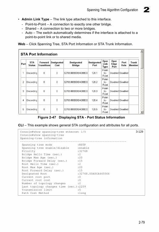
Spanning Tree Algorithm Configuration
2-79
2• Admin Link Type – The link type attached to this interface.
- Point-to-Point – A connection to exactly one other bridge.- Shared – A connection to two or more bridges.- Auto – The switch automatically determines if the interface is attached to a
point-to-point link or to shared media.
Web – Click Spanning Tree, STA Port Information or STA Trunk Information.
Figure 2-47 Displaying STA - Port Status Information
CLI – This example shows general STA configuration and attributes for all ports.
Console#show spanning-tree ethernet 1/5 3-129Console#show spanning-treeSpanning-tree information--------------------------------------------------------------- Spanning tree mode :RSTP Spanning tree enable/disable :enable Priority :32768 Bridge Hello Time (sec.) :2 Bridge Max Age (sec.) :20 Bridge Forward Delay (sec.) :15 Root Hello Time (sec.) :2 Root Max Age (sec.) :20 Root Forward Delay (sec.) :15 Designated Root :32768.00A0CA445566 Current root port :0 Current root cost :0 Number of topology changes :2 Last topology changes time (sec.):2209 Transmission limit :5 Path Cost Method :long
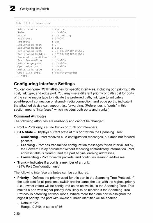
Configuring the Switch
2-80
2
Configuring Interface Settings You can configure RSTP attributes for specific interfaces, including port priority, path cost, link type, and edge port. You may use a different priority or path cost for ports of the same media type to indicate the preferred path, link type to indicate a point-to-point connection or shared-media connection, and edge port to indicate if the attached device can support fast forwarding. (References to “ports” in this section means “interfaces,” which includes both ports and trunks.)
Command AttributesThe following attributes are read-only and cannot be changed:
• Port – Ports only; i.e., no trunks or trunk port members.• STA State – Displays current state of this port within the Spanning Tree:
- Discarding - Port receives STA configuration messages, but does not forward packets.
- Learning - Port has transmitted configuration messages for an interval set by the Forward Delay parameter without receiving contradictory information. Port address table is cleared, and the port begins learning addresses.
- Forwarding - Port forwards packets, and continues learning addresses.• Trunk – Indicates if a port is a member of a trunk.
(STA Port Configuration only)
The following interface attributes can be configured:• Priority – Defines the priority used for this port in the Spanning Tree Protocol. If
the path cost for all ports on a switch are the same, the port with the highest priority (i.e., lowest value) will be configured as an active link in the Spanning Tree. This makes a port with higher priority less likely to be blocked if the Spanning Tree Protocol is detecting network loops. Where more than one port is assigned the highest priority, the port with lowest numeric identifier will be enabled.- Default: 128- Range: 0-240, in steps of 16
---------------------------------------------------------------Eth 1/ 1 information--------------------------------------------------------------- Admin status : enable Role : disable State : discarding Path cost : 100000 Priority : 128 Designated cost : 0 Designated port : 128.1 Designated root : 32768.00A0CA445566 Designated bridge : 32768.00A0CA445566 Forward transitions : 0 Fast forwarding : disable Admin edge port : disable Oper edge port : disable Admin Link type : auto Oper Link type : point-to-point---More---
Spanning Tree Algorithm Configuration
2-81
2• Path Cost – This parameter is used by the STP to determine the best path
between devices. Therefore, lower values should be assigned to ports attached to faster media, and higher values assigned to ports with slower media. (Path cost takes precedence over port priority.) Note that when the Path Cost Method is set to short (page 3-123), the maximum path cost is 65,535. • Range –
- Ethernet: 200,000-20,000,000- Fast Ethernet: 20,000-2,000,000- Gigabit Ethernet: 2,000-200,000
• Default –- Ethernet – Half duplex: 2,000,000; full duplex: 1,000,000; trunk: 500,000- Fast Ethernet – Half duplex: 200,000; full duplex: 100,000; trunk: 50,000- Gigabit Ethernet – Full duplex: 10,000; trunk: 5,000
• Admin Link Type – The link type attached to this interface.• Point-to-Point – A connection to exactly one other bridge.• Shared – A connection to two or more bridges.• Auto – The switch automatically determines if the interface is attached to a
point-to-point link or to shared media. (This is the default setting.)• Admin Edge Port (Fast Forwarding) – You can enable this option if an interface is
attached to a LAN segment that is at the end of a bridged LAN or to an end node. Since end nodes cannot cause forwarding loops, they can pass directly through to the spanning tree forwarding state. Specifying Edge Ports provides quicker convergence for devices such as workstations or servers, retains the current forwarding database to reduce the amount of frame flooding required to rebuild address tables during reconfiguration events, does not cause the spanning tree to initiate reconfiguration when the interface changes state, and also overcomes other STA-related timeout problems. However, remember that Edge Port should only be enabled for ports connected to an end-node device. (Default: Disabled)
• Migration – If at any time the switch detects STP BPDUs, including Configuration or Topology Change Notification BPDUs, it will automatically set the selected interface to forced STP-compatible mode. However, you can also use the Protocol Migration button to manually re-check the appropriate BPDU format (RSTP or STP-compatible) to send on the selected interfaces. (Default: Disabled)
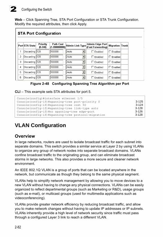
Configuring the Switch
2-82
2Web – Click Spanning Tree, STA Port Configuration or STA Trunk Configuration. Modify the required attributes, then click Apply.
Figure 2-48 Configuring Spanning Tree Algorithm per Port
CLI – This example sets STA attributes for port 5.
VLAN Configuration
OverviewIn large networks, routers are used to isolate broadcast traffic for each subnet into separate domains. This switch provides a similar service at Layer 2 by using VLANs to organize any group of network nodes into separate broadcast domains. VLANs confine broadcast traffic to the originating group, and can eliminate broadcast storms in large networks. This also provides a more secure and cleaner network environment.
An IEEE 802.1Q VLAN is a group of ports that can be located anywhere in the network, but communicate as though they belong to the same physical segment.
VLANs help to simplify network management by allowing you to move devices to a new VLAN without having to change any physical connections. VLANs can be easily organized to reflect departmental groups (such as Marketing or R&D), usage groups (such as e-mail), or multicast groups (used for multimedia applications such as videoconferencing).
VLANs provide greater network efficiency by reducing broadcast traffic, and allow you to make network changes without having to update IP addresses or IP subnets. VLANs inherently provide a high level of network security since traffic must pass through a configured Layer 3 link to reach a different VLAN.
Console(config)#interface ethernet 1/5Console(config-if)#spanning-tree port-priority 0 3-125Console(config-if)#spanning-tree cost 50 3-124Console(config-if)#spanning-tree link-type auto 3-128Console(config-if)#no spanning-tree edge-port 3-126Console(config-if)#spanning-tree protocol-migration 3-128
VLAN Configuration
2-83
2This switch supports the following VLAN features:
• Up to 255 VLANs based on the IEEE 802.1Q standard• Distributed VLAN learning across multiple switches using explicit or implicit tagging
and GVRP protocol• Port overlapping, allowing a port to participate in multiple VLANs• End stations can belong to multiple VLANs• Passing traffic between VLAN-aware and VLAN-unaware devices • Priority tagging
Assigning Ports to VLANsBefore enabling VLANs for the switch, you must first assign each port to the VLAN group(s) in which it will participate. By default all ports are assigned to VLAN 1 as untagged ports. Add a port as a tagged port if you want it to carry traffic for one or more VLANs, and any intermediate network devices or the host at the other end of the connection supports VLANs. Then assign ports on the other VLAN-aware network devices along the path that will carry this traffic to the same VLAN(s), either manually or dynamically using GVRP. However, if you want a port on this switch to participate in one or more VLANs, but none of the intermediate network devices nor the host at the other end of the connection supports VLANs, then you should add this port to the VLAN as an untagged port.
Note: VLAN-tagged frames can pass through VLAN-aware or VLAN-unaware network interconnection devices, but the VLAN tags should be stripped off before passing it on to any end-node host that does not support VLAN tagging.
VLAN Classification – When the switch receives a frame, it classifies the frame in one of two ways. If the frame is untagged, the switch assigns the frame to an associated VLAN (based on the default VLAN ID of the receiving port). But if the frame is tagged, the switch uses the tagged VLAN ID to identify the port broadcast domain of the frame.
Port Overlapping – Port overlapping can be used to allow access to commonly shared network resources among different VLAN groups, such as file servers or printers.
Untagged VLANs – Untagged (or static) VLANs are typically used to reduce broadcast traffic and to increase security. A group of network users assigned to a VLAN form a broadcast domain that is separate from other VLANs configured on the switch. Packets are forwarded only between ports that are designated for the same VLAN. Untagged VLANs can be used to manually isolate user groups or subnets. However, you should use IEEE 802.3 tagged VLANs with GVRP whenever possible to fully automate VLAN registration.
Automatic VLAN Registration – GVRP (GARP VLAN Registration Protocol) defines a system whereby the switch can automatically learn the VLANs to which each end station should be assigned. If an end station (or its network adapter) supports the IEEE 802.1Q VLAN protocol, it can be configured to broadcast a

Configuring the Switch
2-84
2message to your network indicating the VLAN groups it wants to join. When this switch receives these messages, it will automatically place the receiving port in the specified VLANs, and then forward the message to all other ports. When the message arrives at another switch that supports GVRP, it will also place the receiving port in the specified VLANs, and pass the message on to all other ports. VLAN requirements are propagated in this way throughout the network. This allows GVRP-compliant devices to be automatically configured for VLAN groups based solely on endstation requests.
To implement GVRP in a network, first add the host devices to the required VLANs (using the operating system or other application software), so that these VLANs can be propagated onto the network. For both the edge switches attached directly to these hosts, and core switches in the network, enable GVRP on the links between these devices. You should also determine security boundaries in the network and disable GVRP on ports to prevent advertisements being propagated, or forbid ports from joining restricted VLANs.
Note: If you have host devices that do not support GVRP, you should configure static or untagged VLANs for the switch ports connected to these devices (as described in “Adding Static Members to VLANs (VLAN Index)” on page 2-88). But you can still enable GVRP on these edge switches, as well as on the core switches in the network.
Forwarding Tagged/Untagged FramesIf you want to create a small port-based VLAN for devices attached directly to a single switch, you can assign ports to the same untagged VLAN. However, to participate in a VLAN group that crosses several switches, you should create a VLAN for that group and enable tagging on all ports.
Ports can be assigned to multiple tagged or untagged VLANs. Each port on the switch is therefore capable of passing tagged or untagged frames. When forwarding a frame from this switch along a path that contains any VLAN-aware devices, the switch should include VLAN tags. When forwarding a frame from this switch along a path that does not contain any VLAN-aware devices (including the destination host), the switch must first strip off the VLAN tag before forwarding the frame. When the switch receives a tagged frame, it will pass this frame onto the VLAN(s) indicated by the frame tag. However, when this switch receives an untagged frame from a VLAN-unaware device, it first decides where to forward the frame, and then inserts a VLAN tag reflecting the ingress port’s default VID.
Enabling or Disabling GVRP (Global Setting) GARP VLAN Registration Protocol (GVRP) defines a way for switches to exchange VLAN information in order to register VLAN members on ports across the network. VLANs are dynamically configured based on join messages issued by host devices and propagated throughout the network. GVRP must be enabled to permit automatic VLAN registration, and to support VLANs which extend beyond the local switch. (Default: Disabled)
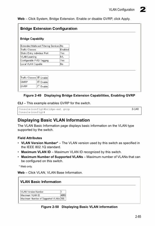
VLAN Configuration
2-85
2Web – Click System, Bridge Extension. Enable or disable GVRP, click Apply.
Figure 2-49 Displaying Bridge Extension Capabilities, Enabling GVRP
CLI – This example enables GVRP for the switch.
Displaying Basic VLAN InformationThe VLAN Basic Information page displays basic information on the VLAN type supported by the switch.
Field Attributes• VLAN Version Number* – The VLAN version used by this switch as specified in
the IEEE 802.1Q standard.• Maximum VLAN ID – Maximum VLAN ID recognized by this switch.• Maximum Number of Supported VLANs – Maximum number of VLANs that can
be configured on this switch. * Web only.
Web – Click VLAN, VLAN Base Information.
Figure 2-50 Displaying Basic VLAN information
Console(config)#bridge-ext gvrp 3-140Console(config)#
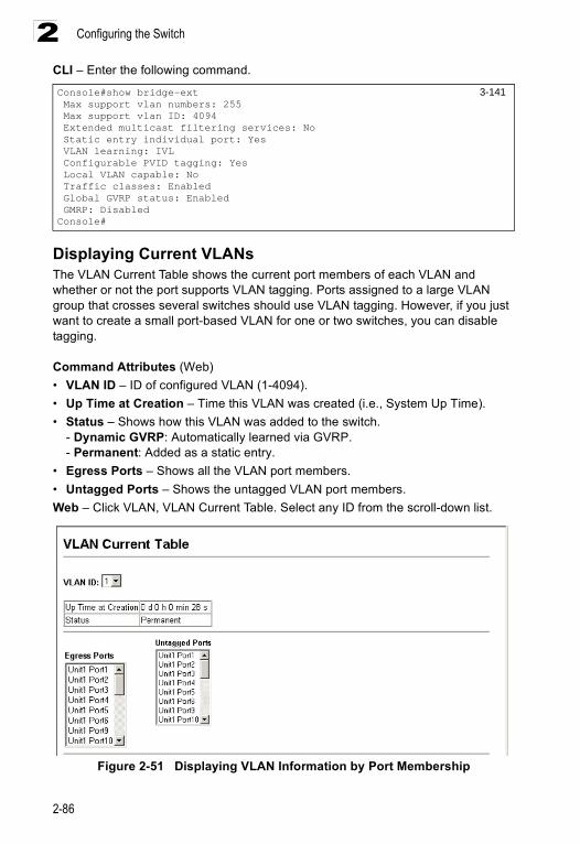
Configuring the Switch
2-86
2CLI – Enter the following command.
Displaying Current VLANsThe VLAN Current Table shows the current port members of each VLAN and whether or not the port supports VLAN tagging. Ports assigned to a large VLAN group that crosses several switches should use VLAN tagging. However, if you just want to create a small port-based VLAN for one or two switches, you can disable tagging.
Command Attributes (Web)• VLAN ID – ID of configured VLAN (1-4094).• Up Time at Creation – Time this VLAN was created (i.e., System Up Time).• Status – Shows how this VLAN was added to the switch.
- Dynamic GVRP: Automatically learned via GVRP.- Permanent: Added as a static entry.
• Egress Ports – Shows all the VLAN port members.• Untagged Ports – Shows the untagged VLAN port members.Web – Click VLAN, VLAN Current Table. Select any ID from the scroll-down list.
Figure 2-51 Displaying VLAN Information by Port Membership
Console#show bridge-ext 3-141 Max support vlan numbers: 255 Max support vlan ID: 4094 Extended multicast filtering services: No Static entry individual port: Yes VLAN learning: IVL Configurable PVID tagging: Yes Local VLAN capable: No Traffic classes: Enabled Global GVRP status: Enabled GMRP: DisabledConsole#
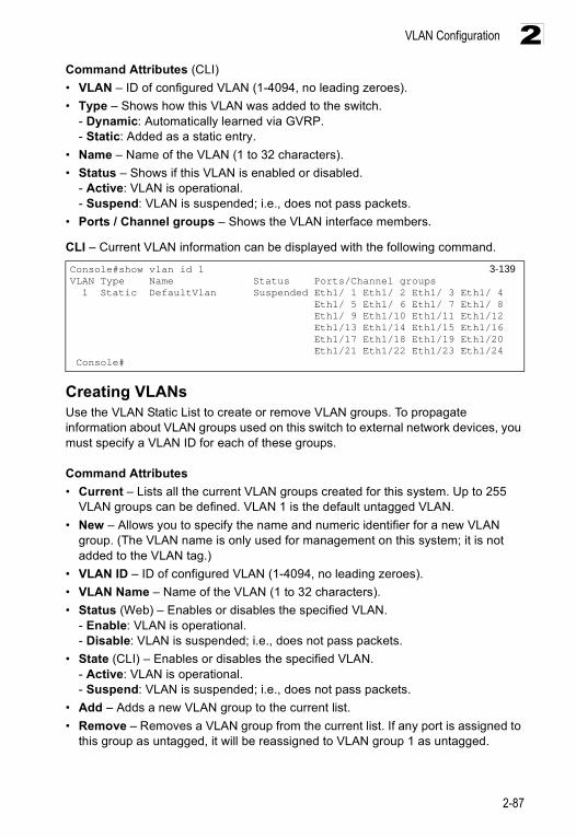
VLAN Configuration
2-87
2Command Attributes (CLI)• VLAN – ID of configured VLAN (1-4094, no leading zeroes).• Type – Shows how this VLAN was added to the switch.
- Dynamic: Automatically learned via GVRP.- Static: Added as a static entry.
• Name – Name of the VLAN (1 to 32 characters).• Status – Shows if this VLAN is enabled or disabled.
- Active: VLAN is operational.- Suspend: VLAN is suspended; i.e., does not pass packets.
• Ports / Channel groups – Shows the VLAN interface members.
CLI – Current VLAN information can be displayed with the following command.
Creating VLANsUse the VLAN Static List to create or remove VLAN groups. To propagate information about VLAN groups used on this switch to external network devices, you must specify a VLAN ID for each of these groups.
Command Attributes• Current – Lists all the current VLAN groups created for this system. Up to 255
VLAN groups can be defined. VLAN 1 is the default untagged VLAN. • New – Allows you to specify the name and numeric identifier for a new VLAN
group. (The VLAN name is only used for management on this system; it is not added to the VLAN tag.)
• VLAN ID – ID of configured VLAN (1-4094, no leading zeroes).• VLAN Name – Name of the VLAN (1 to 32 characters).• Status (Web) – Enables or disables the specified VLAN.
- Enable: VLAN is operational.- Disable: VLAN is suspended; i.e., does not pass packets.
• State (CLI) – Enables or disables the specified VLAN. - Active: VLAN is operational.- Suspend: VLAN is suspended; i.e., does not pass packets.
• Add – Adds a new VLAN group to the current list.• Remove – Removes a VLAN group from the current list. If any port is assigned to
this group as untagged, it will be reassigned to VLAN group 1 as untagged.
Console#show vlan id 1 3-139VLAN Type Name Status Ports/Channel groups 1 Static DefaultVlan Suspended Eth1/ 1 Eth1/ 2 Eth1/ 3 Eth1/ 4 Eth1/ 5 Eth1/ 6 Eth1/ 7 Eth1/ 8 Eth1/ 9 Eth1/10 Eth1/11 Eth1/12 Eth1/13 Eth1/14 Eth1/15 Eth1/16 Eth1/17 Eth1/18 Eth1/19 Eth1/20 Eth1/21 Eth1/22 Eth1/23 Eth1/24 Console#
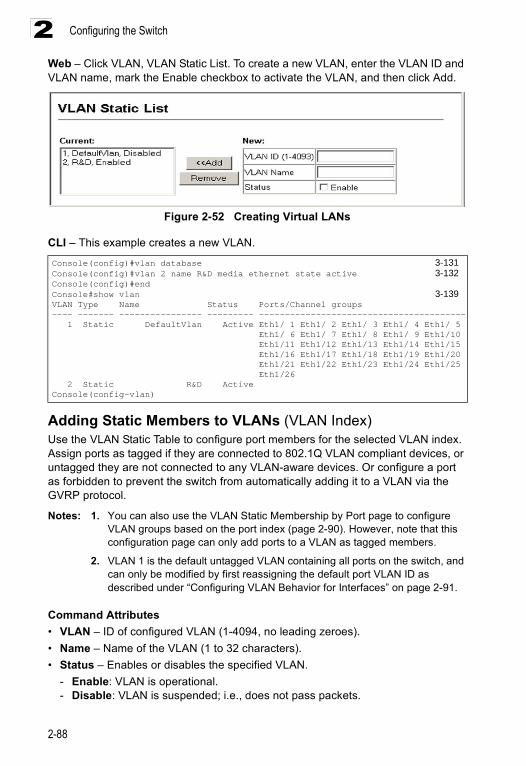
Configuring the Switch
2-88
2Web – Click VLAN, VLAN Static List. To create a new VLAN, enter the VLAN ID and VLAN name, mark the Enable checkbox to activate the VLAN, and then click Add.
Figure 2-52 Creating Virtual LANs
CLI – This example creates a new VLAN.
Adding Static Members to VLANs (VLAN Index)Use the VLAN Static Table to configure port members for the selected VLAN index. Assign ports as tagged if they are connected to 802.1Q VLAN compliant devices, or untagged they are not connected to any VLAN-aware devices. Or configure a port as forbidden to prevent the switch from automatically adding it to a VLAN via the GVRP protocol.
Notes: 1. You can also use the VLAN Static Membership by Port page to configure VLAN groups based on the port index (page 2-90). However, note that this configuration page can only add ports to a VLAN as tagged members.
2. VLAN 1 is the default untagged VLAN containing all ports on the switch, and can only be modified by first reassigning the default port VLAN ID as described under “Configuring VLAN Behavior for Interfaces” on page 2-91.
Command Attributes• VLAN – ID of configured VLAN (1-4094, no leading zeroes).• Name – Name of the VLAN (1 to 32 characters).• Status – Enables or disables the specified VLAN.
- Enable: VLAN is operational.- Disable: VLAN is suspended; i.e., does not pass packets.
Console(config)#vlan database 3-131Console(config)#vlan 2 name R&D media ethernet state active 3-132Console(config)#end Console#show vlan 3-139VLAN Type Name Status Ports/Channel groups---- ------- ---------------- --------- ---------------------------------------- 1 Static DefaultVlan Active Eth1/ 1 Eth1/ 2 Eth1/ 3 Eth1/ 4 Eth1/ 5 Eth1/ 6 Eth1/ 7 Eth1/ 8 Eth1/ 9 Eth1/10 Eth1/11 Eth1/12 Eth1/13 Eth1/14 Eth1/15 Eth1/16 Eth1/17 Eth1/18 Eth1/19 Eth1/20 Eth1/21 Eth1/22 Eth1/23 Eth1/24 Eth1/25 Eth1/26 2 Static R&D ActiveConsole(config-vlan)
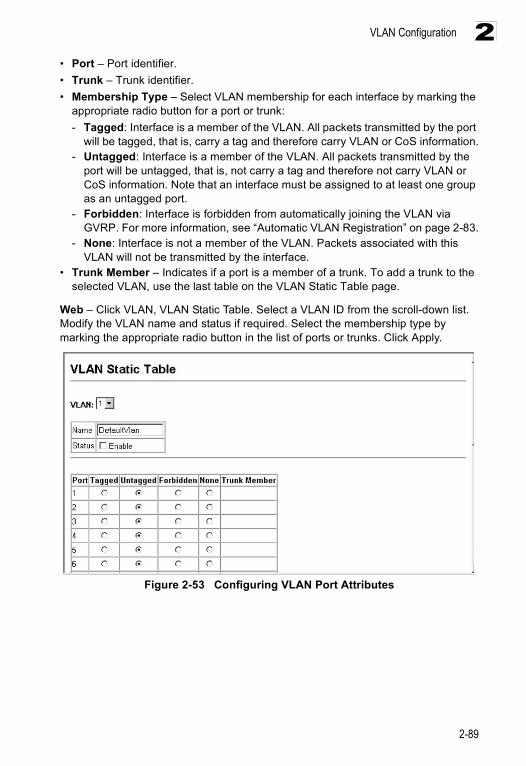
VLAN Configuration
2-89
2• Port – Port identifier.• Trunk – Trunk identifier.• Membership Type – Select VLAN membership for each interface by marking the
appropriate radio button for a port or trunk: - Tagged: Interface is a member of the VLAN. All packets transmitted by the port
will be tagged, that is, carry a tag and therefore carry VLAN or CoS information.- Untagged: Interface is a member of the VLAN. All packets transmitted by the
port will be untagged, that is, not carry a tag and therefore not carry VLAN or CoS information. Note that an interface must be assigned to at least one group as an untagged port.
- Forbidden: Interface is forbidden from automatically joining the VLAN via GVRP. For more information, see “Automatic VLAN Registration” on page 2-83.
- None: Interface is not a member of the VLAN. Packets associated with this VLAN will not be transmitted by the interface.
• Trunk Member – Indicates if a port is a member of a trunk. To add a trunk to the selected VLAN, use the last table on the VLAN Static Table page.
Web – Click VLAN, VLAN Static Table. Select a VLAN ID from the scroll-down list. Modify the VLAN name and status if required. Select the membership type by marking the appropriate radio button in the list of ports or trunks. Click Apply.
Figure 2-53 Configuring VLAN Port Attributes
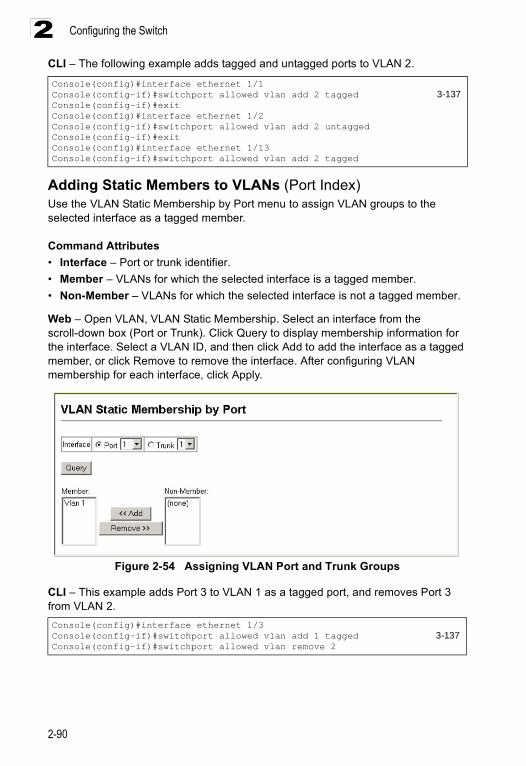
Configuring the Switch
2-90
2CLI – The following example adds tagged and untagged ports to VLAN 2.
Adding Static Members to VLANs (Port Index)Use the VLAN Static Membership by Port menu to assign VLAN groups to the selected interface as a tagged member.
Command Attributes• Interface – Port or trunk identifier.• Member – VLANs for which the selected interface is a tagged member.• Non-Member – VLANs for which the selected interface is not a tagged member.
Web – Open VLAN, VLAN Static Membership. Select an interface from the scroll-down box (Port or Trunk). Click Query to display membership information for the interface. Select a VLAN ID, and then click Add to add the interface as a tagged member, or click Remove to remove the interface. After configuring VLAN membership for each interface, click Apply.
Figure 2-54 Assigning VLAN Port and Trunk Groups
CLI – This example adds Port 3 to VLAN 1 as a tagged port, and removes Port 3 from VLAN 2.
Console(config)#interface ethernet 1/1Console(config-if)#switchport allowed vlan add 2 tagged 3-137Console(config-if)#exitConsole(config)#interface ethernet 1/2Console(config-if)#switchport allowed vlan add 2 untaggedConsole(config-if)#exitConsole(config)#interface ethernet 1/13Console(config-if)#switchport allowed vlan add 2 tagged
Console(config)#interface ethernet 1/3Console(config-if)#switchport allowed vlan add 1 tagged 3-137Console(config-if)#switchport allowed vlan remove 2
VLAN Configuration
2-91
2Configuring VLAN Behavior for InterfacesYou can configure VLAN behavior for specific interfaces, including the default VLAN identifier (PVID), accepted frame types, ingress filtering, GVRP status, and GARP timers.
Command Usage• GVRP – GARP VLAN Registration Protocol defines a way for switches to
exchange VLAN information in order to automatically register VLAN members on interfaces across the network.
• GARP – Group Address Registration Protocol is used by GVRP to register or deregister client attributes for client services within a bridged LAN. The default values for the GARP timers are independent of the media access method or data rate. These values should not be changed unless you are experiencing difficulties with GVRP registration/deregistration.
Command Attributes• PVID – VLAN ID assigned to untagged frames received on the interface. (Default: 1)
- If an interface is not a member of VLAN 1 and you assign its PVID to this VLAN, the interface will automatically be added to VLAN 1 as an untagged member. For all other VLANs, an interface must first be configured as an untagged member before you can assign its PVID to that group.
• Acceptable Frame Type – Sets the interface to accept all frame types, including tagged or untagged frames, or only tagged frames. When set to receive all frame types, any received frames that are untagged are assigned to the default VLAN. (Option: All, Tagged; Default: All)
• Ingress Filtering – If ingress filtering is enabled, incoming frames for VLANs which do not include this ingress port in their member set will be discarded at the ingress port. (Default: Disabled)- Ingress filtering only affects tagged frames. - If ingress filtering is disabled and a port receives frames tagged for VLANs for
which it is not a member, these frames will be flooded to all other ports (except for those VLANs explicitly forbidden on this port).
- If ingress filtering is enabled and a port receives frames tagged for VLANs for which it is not a member, these frames will be discarded.
- Ingress filtering does not affect VLAN independent BPDU frames, such as GVRP or STP. However, they do affect VLAN dependent BPDU frames, such as GMRP.
• GVRP Status – Enables/disables GVRP for the interface. GVRP must be globally enabled for the switch before this setting can take effect. (See “Displaying Bridge Extension Capabilities” on page 2-10.) When disabled, any GVRP packets received on this port will be discarded and no GVRP registrations will be propagated from other ports. (Default: Disabled)
• GARP Join Timer* – The interval between transmitting requests/queries to participate in a VLAN group. (Range: 20-1000 centiseconds; Default: 20)
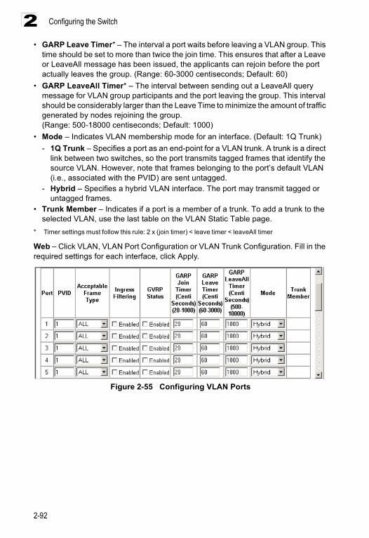
Configuring the Switch
2-92
2• GARP Leave Timer* – The interval a port waits before leaving a VLAN group. This
time should be set to more than twice the join time. This ensures that after a Leave or LeaveAll message has been issued, the applicants can rejoin before the port actually leaves the group. (Range: 60-3000 centiseconds; Default: 60)
• GARP LeaveAll Timer* – The interval between sending out a LeaveAll query message for VLAN group participants and the port leaving the group. This interval should be considerably larger than the Leave Time to minimize the amount of traffic generated by nodes rejoining the group. (Range: 500-18000 centiseconds; Default: 1000)
• Mode – Indicates VLAN membership mode for an interface. (Default: 1Q Trunk)- 1Q Trunk – Specifies a port as an end-point for a VLAN trunk. A trunk is a direct
link between two switches, so the port transmits tagged frames that identify the source VLAN. However, note that frames belonging to the port’s default VLAN (i.e., associated with the PVID) are sent untagged.
- Hybrid – Specifies a hybrid VLAN interface. The port may transmit tagged or untagged frames.
• Trunk Member – Indicates if a port is a member of a trunk. To add a trunk to the selected VLAN, use the last table on the VLAN Static Table page.
* Timer settings must follow this rule: 2 x (join timer) < leave timer < leaveAll timer
Web – Click VLAN, VLAN Port Configuration or VLAN Trunk Configuration. Fill in the required settings for each interface, click Apply.
Figure 2-55 Configuring VLAN Ports
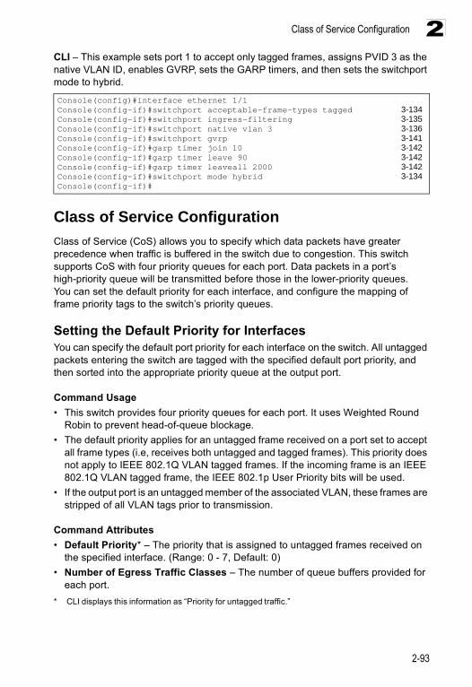
Class of Service Configuration
2-93
2CLI – This example sets port 1 to accept only tagged frames, assigns PVID 3 as the native VLAN ID, enables GVRP, sets the GARP timers, and then sets the switchport mode to hybrid.
Class of Service Configuration Class of Service (CoS) allows you to specify which data packets have greater precedence when traffic is buffered in the switch due to congestion. This switch supports CoS with four priority queues for each port. Data packets in a port’s high-priority queue will be transmitted before those in the lower-priority queues. You can set the default priority for each interface, and configure the mapping of frame priority tags to the switch’s priority queues.
Setting the Default Priority for InterfacesYou can specify the default port priority for each interface on the switch. All untagged packets entering the switch are tagged with the specified default port priority, and then sorted into the appropriate priority queue at the output port.
Command Usage• This switch provides four priority queues for each port. It uses Weighted Round
Robin to prevent head-of-queue blockage.• The default priority applies for an untagged frame received on a port set to accept
all frame types (i.e, receives both untagged and tagged frames). This priority does not apply to IEEE 802.1Q VLAN tagged frames. If the incoming frame is an IEEE 802.1Q VLAN tagged frame, the IEEE 802.1p User Priority bits will be used.
• If the output port is an untagged member of the associated VLAN, these frames are stripped of all VLAN tags prior to transmission.
Command Attributes• Default Priority* – The priority that is assigned to untagged frames received on
the specified interface. (Range: 0 - 7, Default: 0)• Number of Egress Traffic Classes – The number of queue buffers provided for
each port.* CLI displays this information as “Priority for untagged traffic.”
Console(config)#interface ethernet 1/1Console(config-if)#switchport acceptable-frame-types tagged 3-134Console(config-if)#switchport ingress-filtering 3-135Console(config-if)#switchport native vlan 3 3-136Console(config-if)#switchport gvrp 3-141Console(config-if)#garp timer join 10 3-142Console(config-if)#garp timer leave 90 3-142Console(config-if)#garp timer leaveall 2000 3-142Console(config-if)#switchport mode hybrid 3-134Console(config-if)#

Configuring the Switch
2-94
2Web – Click Priority, Default Port Priority or Default Trunk Priority. Modify the default priority for any interface, then click Apply.
Figure 2-56 Configuring Class of Service per Port
CLI – This example assigns a default priority of 5 to port 3.
Mapping CoS Values to Egress QueuesThis switch processes Class of Service (CoS) priority tagged traffic by using four priority queues for each port, with service schedules based on Weighted Round Robin (WRR). Up to 8 separate traffic priorities are defined in IEEE 802.1p. The default priority levels are assigned according to recommendations in the IEEE 802.1p standard as shown in the following table.
Console(config)#interface ethernet 1/3Console(config-if)#switchport priority default 5 3-144Console(config-if)#endConsole#show interfaces switchport ethernet 1/5 3-108Information of Eth 1/5 Broadcast threshold: Enabled, 500 packets/second Lacp status: Disabled VLAN membership mode: Hybrid Ingress rule: Disabled Acceptable frame type: All frames Native VLAN: 1 Priority for untagged traffic: 5 Gvrp status: Disabled Allowed Vlan: 1(u), Forbidden Vlan:Console#
Queue 0 1 2 3
Priority 1,2 0,3 4,5 6,7
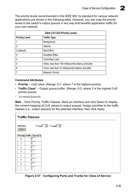
Class of Service Configuration
2-95
2The priority levels recommended in the IEEE 802.1p standard for various network applications are shown in the following table. However, you can map the priority levels to the switch’s output queues in any way that benefits application traffic for your own network.
Command Attributes• Priority – CoS value. (Range: 0-7, where 7 is the highest priority)• Traffic Class* – Output queue buffer. (Range: 0-3, where 3 is the highest CoS
priority queue)* CLI shows Queue ID.
Web – Click Priority, Traffic Classes. Mark an interface and click Select to display the current mapping of CoS values to output queues. Assign priorities to the traffic classes (i.e., output queues) for the selected interface, then click Apply.
Figure 2-57 Configuring Ports and Trunks for Class of Service
Table 2-8 CoS Priority LevelsPriority Level Traffic Type1 Background2 (Spare)0 (default) Best Effort3 Excellent Effort4 Controlled Load5 Video, less than 100 milliseconds latency and jitter6 Voice, less than 10 milliseconds latency and jitter7 Network Control
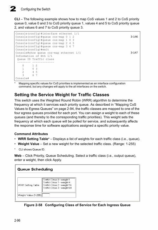
Configuring the Switch
2-96
2CLI – The following example shows how to map CoS values 1 and 2 to CoS priority queue 0, value 0 and 3 to CoS priority queue 1, values 4 and 5 to CoS priority queue 2, and values 6 and 7 to CoS priority queue 3.
* Mapping specific values for CoS priorities is implemented as an interface configuration command, but any changes will apply to the all interfaces on the switch.
Setting the Service Weight for Traffic ClassesThis switch uses the Weighted Round Robin (WRR) algorithm to determine the frequency at which it services each priority queue. As described in “Mapping CoS Values to Egress Queues” on page 2-94, the traffic classes are mapped to one of the four egress queues provided for each port. You can assign a weight to each of these queues (and thereby to the corresponding traffic priorities). This weight sets the frequency at which each queue will be polled for service, and subsequently affects the response time for software applications assigned a specific priority value.
Command Attributes• WRR Setting Table* – Displays a list of weights for each traffic class (i.e., queue).• Weight Value – Set a new weight for the selected traffic class. (Range: 1-255)* CLI shows Queue ID.
Web – Click Priority, Queue Scheduling. Select a traffic class (i.e., output queue), enter a weight, then click Apply.
Figure 2-58 Configuring Class of Service for Each Ingress Queue
Console(config)#interface ethernet 1/1Console(config)#queue cos-map 0 1 2 3-146Console(config)#queue cos-map 1 0 3Console(config)#queue cos-map 2 4 5Console(config)#queue cos-map 3 6 7Console(config)#exitConsole#show queue cos-map ethernet 1/1 3-147Information of Eth 1/1 Queue ID Traffic class -------- ------------- 0 1 2 1 0 3 2 4 5 3 6 7Console#
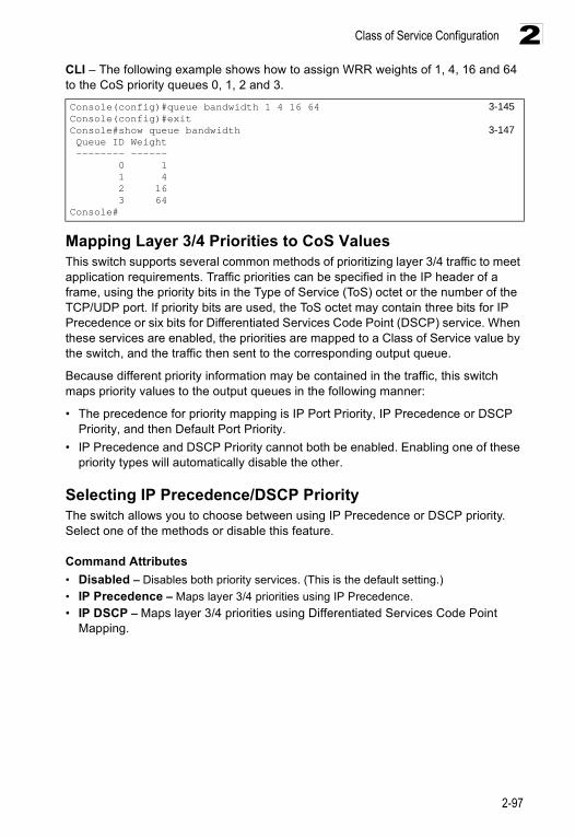
Class of Service Configuration
2-97
2CLI – The following example shows how to assign WRR weights of 1, 4, 16 and 64 to the CoS priority queues 0, 1, 2 and 3.
Mapping Layer 3/4 Priorities to CoS ValuesThis switch supports several common methods of prioritizing layer 3/4 traffic to meet application requirements. Traffic priorities can be specified in the IP header of a frame, using the priority bits in the Type of Service (ToS) octet or the number of the TCP/UDP port. If priority bits are used, the ToS octet may contain three bits for IP Precedence or six bits for Differentiated Services Code Point (DSCP) service. When these services are enabled, the priorities are mapped to a Class of Service value by the switch, and the traffic then sent to the corresponding output queue.
Because different priority information may be contained in the traffic, this switch maps priority values to the output queues in the following manner:
• The precedence for priority mapping is IP Port Priority, IP Precedence or DSCP Priority, and then Default Port Priority.
• IP Precedence and DSCP Priority cannot both be enabled. Enabling one of these priority types will automatically disable the other.
Selecting IP Precedence/DSCP PriorityThe switch allows you to choose between using IP Precedence or DSCP priority. Select one of the methods or disable this feature.
Command Attributes• Disabled – Disables both priority services. (This is the default setting.)• IP Precedence – Maps layer 3/4 priorities using IP Precedence.• IP DSCP – Maps layer 3/4 priorities using Differentiated Services Code Point
Mapping.
Console(config)#queue bandwidth 1 4 16 64 3-145Console(config)#exitConsole#show queue bandwidth 3-147 Queue ID Weight -------- ------ 0 1 1 4 2 16 3 64Console#
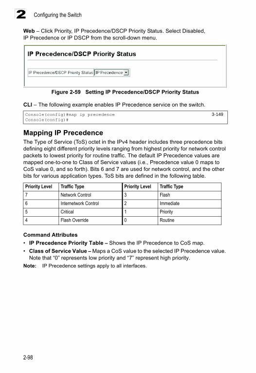
Configuring the Switch
2-98
2Web – Click Priority, IP Precedence/DSCP Priority Status. Select Disabled, IP Precedence or IP DSCP from the scroll-down menu.
Figure 2-59 Setting IP Precedence/DSCP Priority Status
CLI – The following example enables IP Precedence service on the switch.
Mapping IP PrecedenceThe Type of Service (ToS) octet in the IPv4 header includes three precedence bits defining eight different priority levels ranging from highest priority for network control packets to lowest priority for routine traffic. The default IP Precedence values are mapped one-to-one to Class of Service values (i.e., Precedence value 0 maps to CoS value 0, and so forth). Bits 6 and 7 are used for network control, and the other bits for various application types. ToS bits are defined in the following table.
Command Attributes• IP Precedence Priority Table – Shows the IP Precedence to CoS map.• Class of Service Value – Maps a CoS value to the selected IP Precedence value.
Note that “0” represents low priority and “7” represent high priority.Note: IP Precedence settings apply to all interfaces.
Console(config)#map ip precedence 3-149Console(config)#
Priority Level Traffic Type Priority Level Traffic Type7 Network Control 3 Flash6 Internetwork Control 2 Immediate5 Critical 1 Priority4 Flash Override 0 Routine
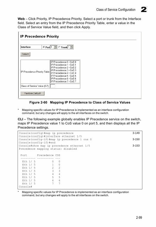
Class of Service Configuration
2-99
2Web – Click Priority, IP Precedence Priority. Select a port or trunk from the Interface field. Select an entry from the IP Precedence Priority Table, enter a value in the Class of Service Value field, and then click Apply.
Figure 2-60 Mapping IP Precedence to Class of Service Values
* Mapping specific values for IP Precedence is implemented as an interface configuration command, but any changes will apply to the all interfaces on the switch.
CLI – The following example globally enables IP Precedence service on the switch, maps IP Precedence value 1 to CoS value 0 on port 5, and then displays all the IP Precedence settings.
* Mapping specific values for IP Precedence is implemented as an interface configuration command, but any changes will apply to the all interfaces on the switch.
Console(config)#map ip precedence 3-149Console(config)#interface ethernet 1/5Console(config-if)#map ip precedence 1 cos 0 3-150Console(config-if)#endConsole#show map ip precedence ethernet 1/5 3-153Precedence mapping status: disabled
Port Precedence COS --------- ---------- --- Eth 1/ 5 0 0 Eth 1/ 5 1 0 Eth 1/ 5 2 2 Eth 1/ 5 3 3 Eth 1/ 5 4 4 Eth 1/ 5 5 5 Eth 1/ 5 6 6 Eth 1/ 5 7 7Console#
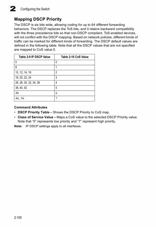
Configuring the Switch
2-100
2Mapping DSCP PriorityThe DSCP is six bits wide, allowing coding for up to 64 different forwarding behaviors. The DSCP replaces the ToS bits, and it retains backward compatibility with the three precedence bits so that non-DSCP compliant, ToS-enabled devices, will not conflict with the DSCP mapping. Based on network policies, different kinds of traffic can be marked for different kinds of forwarding. The DSCP default values are defined in the following table. Note that all the DSCP values that are not specified are mapped to CoS value 0.
Command Attributes• DSCP Priority Table – Shows the DSCP Priority to CoS map.• Class of Service Value – Maps a CoS value to the selected DSCP Priority value.
Note that “0” represents low priority and “7” represent high priority.Note: IP DSCP settings apply to all interfaces.
Table 2-9 IP DSCP Value Table 2-10 CoS Value0 08 110, 12, 14, 16 218, 20, 22, 24 326, 28, 30, 32, 34, 36 438, 40, 42 548 646, 56 7
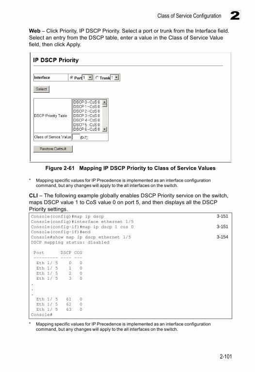
Class of Service Configuration
2-101
2Web – Click Priority, IP DSCP Priority. Select a port or trunk from the Interface field. Select an entry from the DSCP table, enter a value in the Class of Service Value field, then click Apply.
Figure 2-61 Mapping IP DSCP Priority to Class of Service Values
* Mapping specific values for IP Precedence is implemented as an interface configuration command, but any changes will apply to the all interfaces on the switch.
CLI – The following example globally enables DSCP Priority service on the switch, maps DSCP value 1 to CoS value 0 on port 5, and then displays all the DSCP Priority settings.
* Mapping specific values for IP Precedence is implemented as an interface configuration command, but any changes will apply to the all interfaces on the switch.
Console(config)#map ip dscp 3-151Console(config)#interface ethernet 1/5Console(config-if)#map ip dscp 1 cos 0 3-151Console(config-if)#endConsole#show map ip dscp ethernet 1/5 3-154DSCP mapping status: disabled
Port DSCP COS --------- ---- --- Eth 1/ 5 0 0 Eth 1/ 5 1 0 Eth 1/ 5 2 0 Eth 1/ 5 3 0... Eth 1/ 5 61 0 Eth 1/ 5 62 0 Eth 1/ 5 63 0Console#
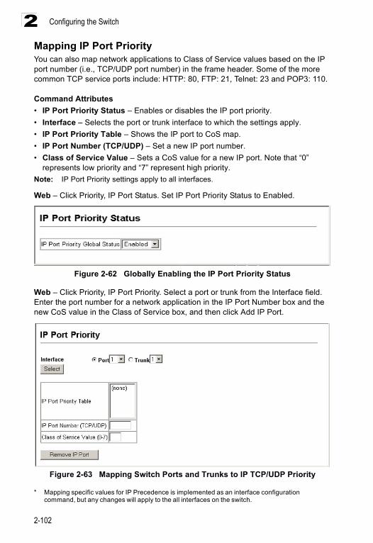
Configuring the Switch
2-102
2Mapping IP Port PriorityYou can also map network applications to Class of Service values based on the IP port number (i.e., TCP/UDP port number) in the frame header. Some of the more common TCP service ports include: HTTP: 80, FTP: 21, Telnet: 23 and POP3: 110.
Command Attributes• IP Port Priority Status – Enables or disables the IP port priority.• Interface – Selects the port or trunk interface to which the settings apply.• IP Port Priority Table – Shows the IP port to CoS map.• IP Port Number (TCP/UDP) – Set a new IP port number.• Class of Service Value – Sets a CoS value for a new IP port. Note that “0”
represents low priority and “7” represent high priority.Note: IP Port Priority settings apply to all interfaces.
Web – Click Priority, IP Port Status. Set IP Port Priority Status to Enabled.
Figure 2-62 Globally Enabling the IP Port Priority Status
Web – Click Priority, IP Port Priority. Select a port or trunk from the Interface field. Enter the port number for a network application in the IP Port Number box and the new CoS value in the Class of Service box, and then click Add IP Port.
Figure 2-63 Mapping Switch Ports and Trunks to IP TCP/UDP Priority
* Mapping specific values for IP Precedence is implemented as an interface configuration command, but any changes will apply to the all interfaces on the switch.
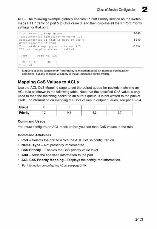
Class of Service Configuration
2-103
2CLI – The following example globally enables IP Port Priority service on the switch, maps HTTP traffic on port 5 to CoS value 0, and then displays all the IP Port Priority settings for that port.
* Mapping specific values for IP Port Priority is implemented as an interface configuration command, but any changes will apply to the all interfaces on the switch.
Mapping CoS Values to ACLsUse the ACL CoS Mapping page to set the output queue for packets matching an ACL rule as shown in the following table. Note that the specified CoS value is only used to map the matching packet to an output queue; it is not written to the packet itself. For information on mapping the CoS values to output queues, see page 2-94.
Command UsageYou must configure an ACL mask before you can map CoS values to the rule.
Command Attributes• Port – Selects the port to which the ACL CoS is configured on.• Name, Type – Not presently implemented.• CoS Priority – Enables the CoS priority value level.• Add – Adds the specified information to the port.• ACL CoS Priority Mapping – Displays the configured information.* For information on configuring ACLs, see page 2-40.
Console(config)#map ip port 3-148Console(config)#interface ethernet 1/5Console(config-if)#map ip port 80 cos 0 3-149Console(config-if)#endConsole#show map ip port ethernet 1/5 3-152TCP port mapping status: disabled
Port Port no. COS --------- -------- --- Eth 1/ 5 80 0Console#
Queue 0 1 2 3
Priority 1,2 0,3 4,5 6,7
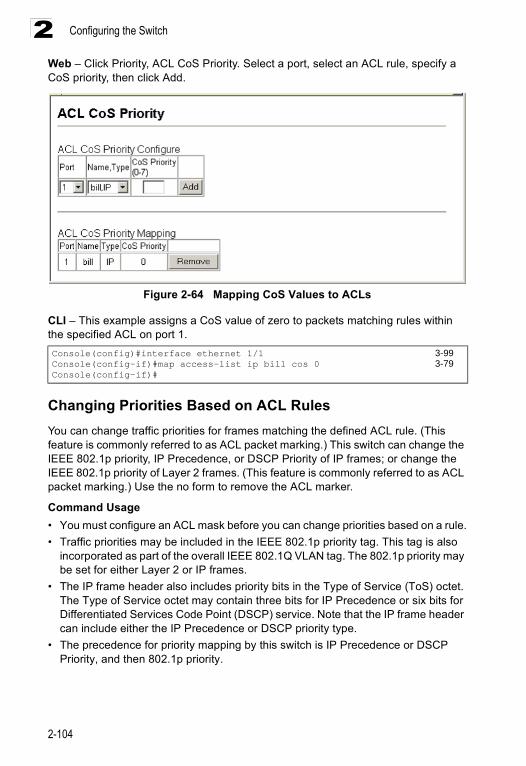
Configuring the Switch
2-104
2Web – Click Priority, ACL CoS Priority. Select a port, select an ACL rule, specify a CoS priority, then click Add.
Figure 2-64 Mapping CoS Values to ACLs
CLI – This example assigns a CoS value of zero to packets matching rules within the specified ACL on port 1.
Changing Priorities Based on ACL RulesYou can change traffic priorities for frames matching the defined ACL rule. (This feature is commonly referred to as ACL packet marking.) This switch can change the IEEE 802.1p priority, IP Precedence, or DSCP Priority of IP frames; or change the IEEE 802.1p priority of Layer 2 frames. (This feature is commonly referred to as ACL packet marking.) Use the no form to remove the ACL marker.
Command Usage• You must configure an ACL mask before you can change priorities based on a rule.• Traffic priorities may be included in the IEEE 802.1p priority tag. This tag is also
incorporated as part of the overall IEEE 802.1Q VLAN tag. The 802.1p priority may be set for either Layer 2 or IP frames.
• The IP frame header also includes priority bits in the Type of Service (ToS) octet. The Type of Service octet may contain three bits for IP Precedence or six bits for Differentiated Services Code Point (DSCP) service. Note that the IP frame header can include either the IP Precedence or DSCP priority type.
• The precedence for priority mapping by this switch is IP Precedence or DSCP Priority, and then 802.1p priority.
Console(config)#interface ethernet 1/1 3-99Console(config-if)#map access-list ip bill cos 0 3-79Console(config-if)#
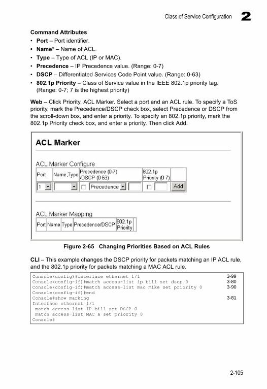
Class of Service Configuration
2-105
2Command Attributes• Port – Port identifier.• Name* – Name of ACL. • Type – Type of ACL (IP or MAC). • Precedence – IP Precedence value. (Range: 0-7)• DSCP – Differentiated Services Code Point value. (Range: 0-63)• 802.1p Priority – Class of Service value in the IEEE 802.1p priority tag.
(Range: 0-7; 7 is the highest priority)
Web – Click Priority, ACL Marker. Select a port and an ACL rule. To specify a ToS priority, mark the Precedence/DSCP check box, select Precedence or DSCP from the scroll-down box, and enter a priority. To specify an 802.1p priority, mark the 802.1p Priority check box, and enter a priority. Then click Add.
Figure 2-65 Changing Priorities Based on ACL Rules
CLI – This example changes the DSCP priority for packets matching an IP ACL rule, and the 802.1p priority for packets matching a MAC ACL rule.Console(config)#interface ethernet 1/1 3-99Console(config-if)#match access-list ip bill set dscp 0 3-80Console(config-if)#match access-list mac mike set priority 0 3-90Console(config-if)#endConsole#show marking 3-81Interface ethernet 1/1 match access-list IP bill set DSCP 0 match access-list MAC a set priority 0Console#
Configuring the Switch
2-106
2Multicast Filtering Multicasting is used to support real-time applications such as video conferencing or streaming audio. A multicast server does not have to establish a separate connection with each client. It merely broadcasts its service to the network, and any hosts that want to receive the multicast register with their local multicast switch/router. Although this approach reduces the network overhead required by a multicast server, the broadcast traffic must be carefully pruned at every multicast switch/router it passes through to ensure that traffic is only passed on the hosts which subscribed to this service.
This switch uses IGMP (Internet Group Management Protocol) to query for any attached hosts that want to receive a specific multicast service. It identifies the ports containing hosts requesting to join the service and sends data out to those ports only. It then propagates the service request up to any neighboring multicast switch/router to ensure that it will continue to receive the multicast service. This procedure is called multicast filtering.
The purpose of IP multicast filtering is to optimize a switched network’s performance, so multicast packets will only be forwarded to those ports containing multicast group hosts or multicast routers/switches, instead of flooding traffic to all ports in the subnet (VLAN).
Configuring IGMP Snooping ParametersYou can configure the switch to forward multicast traffic intelligently. Based on the IGMP query and report messages, the switch forwards traffic only to the ports that request multicast traffic. This prevents the switch from broadcasting the traffic to all ports and possibly disrupting network performance.
Command Usage• IGMP Snooping – This switch can passively snoop on IGMP Query and Report
packets transferred between IP multicast routers/switches and IP multicast host groups to identify the IP multicast group members. It simply monitors the IGMP packets passing through it, picks out the group registration information, and configures multicast filters accordingly.
• IGMP Query – A router, or multicast-enabled switch, can periodically ask their hosts if they want to receive multicast traffic. If there is more than one router/switch on the LAN performing IP multicasting, one of these devices is elected “querier” and assumes the role of querying the LAN for group members. It then propagates the service requests on to any adjacent multicast switch/router to ensure that it will continue to receive the multicast service.
Note: Multicast routers use this information, along with a multicast routing protocol such as DVMRP or PIM, to support IP multicasting across the Internet.
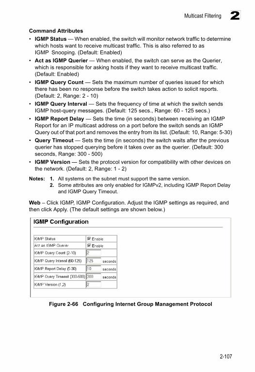
Multicast Filtering
2-107
2Command Attributes• IGMP Status — When enabled, the switch will monitor network traffic to determine
which hosts want to receive multicast traffic. This is also referred to as IGMP Snooping. (Default: Enabled)
• Act as IGMP Querier — When enabled, the switch can serve as the Querier, which is responsible for asking hosts if they want to receive multicast traffic. (Default: Enabled)
• IGMP Query Count — Sets the maximum number of queries issued for which there has been no response before the switch takes action to solicit reports. (Default: 2, Range: 2 - 10)
• IGMP Query Interval — Sets the frequency of time at which the switch sends IGMP host-query messages. (Default: 125 secs., Range: 60 - 125 secs.)
• IGMP Report Delay — Sets the time (in seconds) between receiving an IGMP Report for an IP multicast address on a port before the switch sends an IGMP Query out of that port and removes the entry from its list. (Default: 10, Range: 5-30)
• Query Timeout — Sets the time (in seconds) the switch waits after the previous querier has stopped querying before it takes over as the querier. (Default: 300 seconds, Range: 300 - 500)
• IGMP Version — Sets the protocol version for compatibility with other devices on the network. (Default: 2, Range: 1 - 2)
Notes: 1. All systems on the subnet must support the same version. 2. Some attributes are only enabled for IGMPv2, including IGMP Report Delay
and IGMP Query Timeout.
Web – Click IGMP, IGMP Configuration. Adjust the IGMP settings as required, and then click Apply. (The default settings are shown below.)
Figure 2-66 Configuring Internet Group Management Protocol
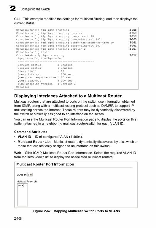
Configuring the Switch
2-108
2CLI – This example modifies the settings for multicast filtering, and then displays the current status.
Displaying Interfaces Attached to a Multicast RouterMulticast routers that are attached to ports on the switch use information obtained from IGMP, along with a multicast routing protocol such as DVMRP, to support IP multicasting across the Internet. These routers may be dynamically discovered by the switch or statically assigned to an interface on the switch.You can use the Multicast Router Port Information page to display the ports on this switch attached to a neighboring multicast router/switch for each VLAN ID.
Command Attributes• VLAN ID – ID of configured VLAN (1-4094).• Multicast Router List – Multicast routers dynamically discovered by this switch or
those that are statically assigned to an interface on this switch.
Web – Click IGMP, Multicast Router Port Information. Select the required VLAN ID from the scroll-down list to display the associated multicast routers.
Figure 2-67 Mapping Multicast Switch Ports to VLANs
Console(config)#ip igmp snooping 3-156Console(config)#ip igmp snooping querier 3-159Console(config)#ip igmp snooping query-count 10 3-159Console(config)#ip igmp snooping query-interval 100 3-160Console(config)#ip igmp snooping query-max-response-time 20 3-161Console(config)#ip igmp snooping query-time-out 300 3-161Console(config)#ip igmp snooping version 2 3-157Console(config)#exitConsole#show ip igmp snooping 3-157 Igmp Snooping Configuration ---------------------------------------------- Service status : Enabled Querier status : Enabled Query count : 10 Query interval : 100 sec Query max response time : 20 sec Query time-out : 300 sec IGMP snooping version : Version 2Console#
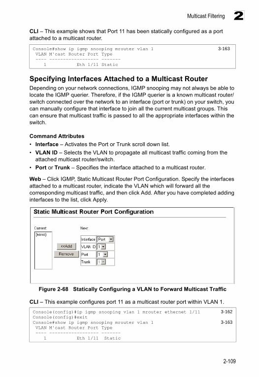
Multicast Filtering
2-109
2CLI – This example shows that Port 11 has been statically configured as a port attached to a multicast router.
Specifying Interfaces Attached to a Multicast RouterDepending on your network connections, IGMP snooping may not always be able to locate the IGMP querier. Therefore, if the IGMP querier is a known multicast router/switch connected over the network to an interface (port or trunk) on your switch, you can manually configure that interface to join all the current multicast groups. This can ensure that multicast traffic is passed to all the appropriate interfaces within the switch.
Command Attributes• Interface – Activates the Port or Trunk scroll down list.• VLAN ID – Selects the VLAN to propagate all multicast traffic coming from the
attached multicast router/switch.• Port or Trunk – Specifies the interface attached to a multicast router.
Web – Click IGMP, Static Multicast Router Port Configuration. Specify the interfaces attached to a multicast router, indicate the VLAN which will forward all the corresponding multicast traffic, and then click Add. After you have completed adding interfaces to the list, click Apply.
Figure 2-68 Statically Configuring a VLAN to Forward Multicast Traffic
CLI – This example configures port 11 as a multicast router port within VLAN 1.
Console#show ip igmp snooping mrouter vlan 1 3-163 VLAN M'cast Router Port Type ---- ------------------ ------- 1 Eth 1/11 Static
Console(config)#ip igmp snooping vlan 1 mrouter ethernet 1/11 3-162Console(config)#exitConsole#show ip igmp snooping mrouter vlan 1 3-163 VLAN M'cast Router Port Type ---- ------------------ ------- 1 Eth 1/11 Static
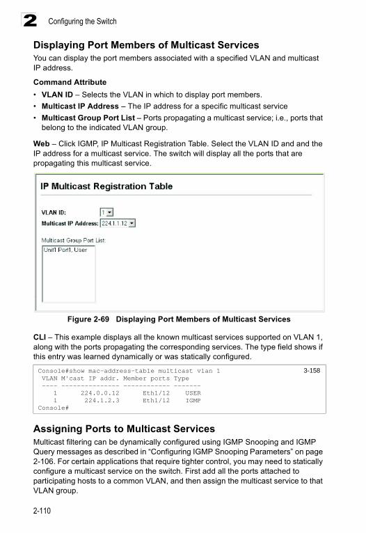
Configuring the Switch
2-110
2Displaying Port Members of Multicast ServicesYou can display the port members associated with a specified VLAN and multicast IP address.
Command Attribute• VLAN ID – Selects the VLAN in which to display port members.• Multicast IP Address – The IP address for a specific multicast service• Multicast Group Port List – Ports propagating a multicast service; i.e., ports that
belong to the indicated VLAN group.
Web – Click IGMP, IP Multicast Registration Table. Select the VLAN ID and and the IP address for a multicast service. The switch will display all the ports that are propagating this multicast service.
Figure 2-69 Displaying Port Members of Multicast Services
CLI – This example displays all the known multicast services supported on VLAN 1, along with the ports propagating the corresponding services. The type field shows if this entry was learned dynamically or was statically configured.
Assigning Ports to Multicast ServicesMulticast filtering can be dynamically configured using IGMP Snooping and IGMP Query messages as described in “Configuring IGMP Snooping Parameters” on page 2-106. For certain applications that require tighter control, you may need to statically configure a multicast service on the switch. First add all the ports attached to participating hosts to a common VLAN, and then assign the multicast service to that VLAN group.
Console#show mac-address-table multicast vlan 1 3-158 VLAN M'cast IP addr. Member ports Type ---- --------------- ------------ ------- 1 224.0.0.12 Eth1/12 USER 1 224.1.2.3 Eth1/12 IGMPConsole#
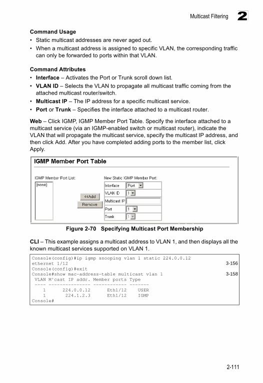
Multicast Filtering
2-111
2Command Usage• Static multicast addresses are never aged out.• When a multicast address is assigned to specific VLAN, the corresponding traffic
can only be forwarded to ports within that VLAN.
Command Attributes• Interface – Activates the Port or Trunk scroll down list.• VLAN ID – Selects the VLAN to propagate all multicast traffic coming from the
attached multicast router/switch.• Multicast IP – The IP address for a specific multicast service.• Port or Trunk – Specifies the interface attached to a multicast router.
Web – Click IGMP, IGMP Member Port Table. Specify the interface attached to a multicast service (via an IGMP-enabled switch or multicast router), indicate the VLAN that will propagate the multicast service, specify the multicast IP address, and then click Add. After you have completed adding ports to the member list, click Apply.
Figure 2-70 Specifying Multicast Port Membership
CLI – This example assigns a multicast address to VLAN 1, and then displays all the known multicast services supported on VLAN 1.Console(config)#ip igmp snooping vlan 1 static 224.0.0.12 ethernet 1/12 3-156Console(config)#exitConsole#show mac-address-table multicast vlan 1 3-158 VLAN M'cast IP addr. Member ports Type ---- --------------- ------------ ------- 1 224.0.0.12 Eth1/12 USER 1 224.1.2.3 Eth1/12 IGMPConsole#

Configuring the Switch
2-112
2
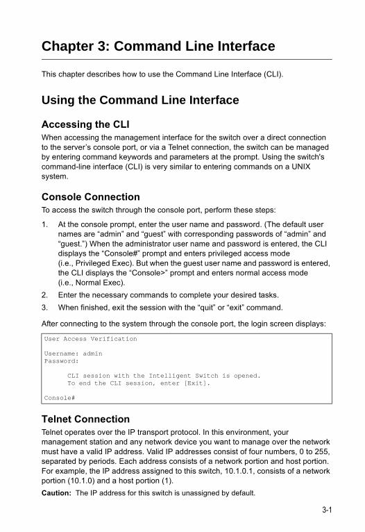
3-1
Chapter 3: Command Line Interface
This chapter describes how to use the Command Line Interface (CLI).
Using the Command Line Interface
Accessing the CLIWhen accessing the management interface for the switch over a direct connection to the server’s console port, or via a Telnet connection, the switch can be managed by entering command keywords and parameters at the prompt. Using the switch's command-line interface (CLI) is very similar to entering commands on a UNIX system.
Console ConnectionTo access the switch through the console port, perform these steps:
1. At the console prompt, enter the user name and password. (The default user names are “admin” and “guest” with corresponding passwords of “admin” and “guest.”) When the administrator user name and password is entered, the CLI displays the “Console#” prompt and enters privileged access mode (i.e., Privileged Exec). But when the guest user name and password is entered, the CLI displays the “Console>” prompt and enters normal access mode (i.e., Normal Exec).
2. Enter the necessary commands to complete your desired tasks. 3. When finished, exit the session with the “quit” or “exit” command.
After connecting to the system through the console port, the login screen displays:
Telnet ConnectionTelnet operates over the IP transport protocol. In this environment, your management station and any network device you want to manage over the network must have a valid IP address. Valid IP addresses consist of four numbers, 0 to 255, separated by periods. Each address consists of a network portion and host portion. For example, the IP address assigned to this switch, 10.1.0.1, consists of a network portion (10.1.0) and a host portion (1).Caution: The IP address for this switch is unassigned by default.
User Access Verification
Username: adminPassword:
CLI session with the Intelligent Switch is opened. To end the CLI session, enter [Exit].
Console#
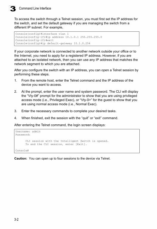
Command Line Interface
3-2
3To access the switch through a Telnet session, you must first set the IP address for the switch, and set the default gateway if you are managing the switch from a different IP subnet. For example,
If your corporate network is connected to another network outside your office or to the Internet, you need to apply for a registered IP address. However, if you are attached to an isolated network, then you can use any IP address that matches the network segment to which you are attached.
After you configure the switch with an IP address, you can open a Telnet session by performing these steps.
1. From the remote host, enter the Telnet command and the IP address of the device you want to access.
2. At the prompt, enter the user name and system password. The CLI will display the “Vty-0#” prompt for the administrator to show that you are using privileged access mode (i.e., Privileged Exec), or “Vty-0>” for the guest to show that you are using normal access mode (i.e., Normal Exec).
3. Enter the necessary commands to complete your desired tasks.
4. When finished, exit the session with the “quit” or “exit” command.
After entering the Telnet command, the login screen displays:
Caution: You can open up to four sessions to the device via Telnet.
Console(config)#interface vlan 1Console(config-if)#ip address 10.1.0.1 255.255.255.0Console(config-if)#exitConsole(config)#ip default-gateway 10.1.0.254
Username: adminPassword:
CLI session with the Intelligent Switch is opened. To end the CLI session, enter [Exit].
Console#
Entering Commands
3-3
3Entering CommandsThis section describes how to enter CLI commands.
Keywords and ArgumentsA CLI command is a series of keywords and arguments. Keywords identify a command, and arguments specify configuration parameters. For example, in the command “show interfaces status ethernet 1/5,” show interfaces and status are keywords, ethernet is an argument that specifies the interface type, and 1/5 specifies the unit/port.
You can enter commands as follows:
• To enter a simple command, enter the command keyword. • To enter multiple commands, enter each command in the required order. For
example, to enable Privileged Exec command mode, and display the startup configuration, enter:Console>enableConsole#show startup-config
• To enter commands that require parameters, enter the required parameters after the command keyword. For example, to set a password for the administrator, enter:Console(config)#username admin password 0 smith
Minimum AbbreviationThe CLI will accept a minimum number of characters that uniquely identify a command. For example, the command “configure” can be entered as con. If an entry is ambiguous, the system will prompt for further input.
Command CompletionIf you terminate input with a Tab key, the CLI will print the remaining characters of a partial keyword up to the point of ambiguity. In the “logging history” example, typing log followed by a tab will result in printing the command up to “logging.”
Getting Help on CommandsYou can display a brief description of the help system by entering the help command. You can also display command syntax by using the “?” character to list keywords or parameters.
Showing CommandsIf you enter a “?” at the command prompt, the system will display the first level of keywords for the current command class (Normal Exec or Privileged Exec) or configuration class (Global, ACL, Interface, Line, or VLAN Database). You can also display a list of valid keywords for a specific command. For example, the command
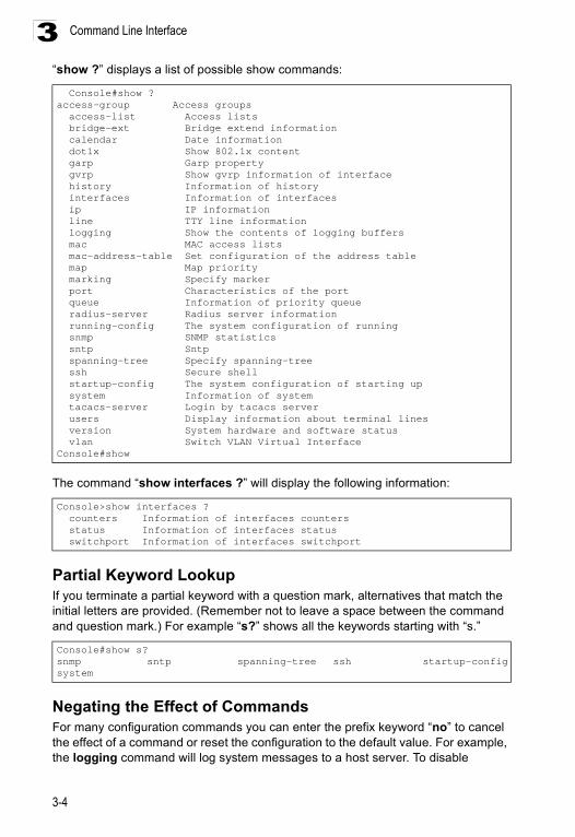
Command Line Interface
3-4
3“show ?” displays a list of possible show commands:
The command “show interfaces ?” will display the following information:
Partial Keyword LookupIf you terminate a partial keyword with a question mark, alternatives that match the initial letters are provided. (Remember not to leave a space between the command and question mark.) For example “s?” shows all the keywords starting with “s.”
Negating the Effect of CommandsFor many configuration commands you can enter the prefix keyword “no” to cancel the effect of a command or reset the configuration to the default value. For example, the logging command will log system messages to a host server. To disable
Console#show ?access-group Access groups access-list Access lists bridge-ext Bridge extend information calendar Date information dot1x Show 802.1x content garp Garp property gvrp Show gvrp information of interface history Information of history interfaces Information of interfaces ip IP information line TTY line information logging Show the contents of logging buffers mac MAC access lists mac-address-table Set configuration of the address table map Map priority marking Specify marker port Characteristics of the port queue Information of priority queue radius-server Radius server information running-config The system configuration of running snmp SNMP statistics sntp Sntp spanning-tree Specify spanning-tree ssh Secure shell startup-config The system configuration of starting up system Information of system tacacs-server Login by tacacs server users Display information about terminal lines version System hardware and software status vlan Switch VLAN Virtual InterfaceConsole#show
Console>show interfaces ? counters Information of interfaces counters status Information of interfaces status switchport Information of interfaces switchport
Console#show s?snmp sntp spanning-tree ssh startup-configsystem
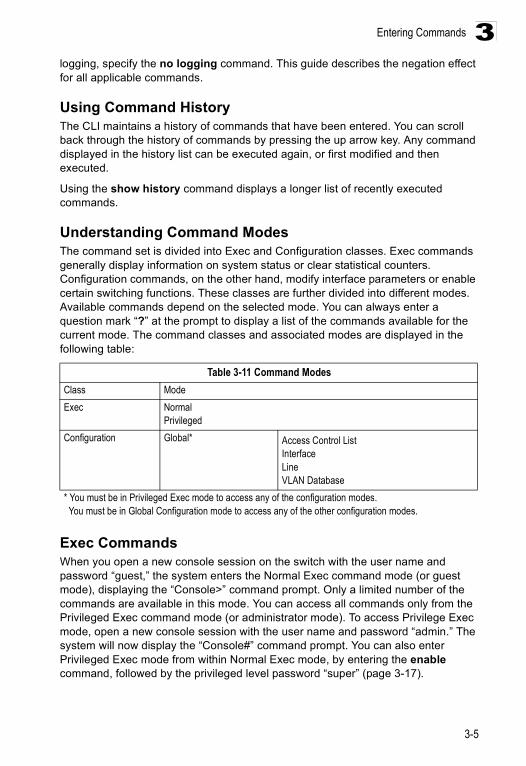
Entering Commands
3-5
3logging, specify the no logging command. This guide describes the negation effect for all applicable commands.
Using Command HistoryThe CLI maintains a history of commands that have been entered. You can scroll back through the history of commands by pressing the up arrow key. Any command displayed in the history list can be executed again, or first modified and then executed.
Using the show history command displays a longer list of recently executed commands.
Understanding Command ModesThe command set is divided into Exec and Configuration classes. Exec commands generally display information on system status or clear statistical counters. Configuration commands, on the other hand, modify interface parameters or enable certain switching functions. These classes are further divided into different modes. Available commands depend on the selected mode. You can always enter a question mark “?” at the prompt to display a list of the commands available for the current mode. The command classes and associated modes are displayed in the following table:
Exec CommandsWhen you open a new console session on the switch with the user name and password “guest,” the system enters the Normal Exec command mode (or guest mode), displaying the “Console>” command prompt. Only a limited number of the commands are available in this mode. You can access all commands only from the Privileged Exec command mode (or administrator mode). To access Privilege Exec mode, open a new console session with the user name and password “admin.” The system will now display the “Console#” command prompt. You can also enter Privileged Exec mode from within Normal Exec mode, by entering the enable command, followed by the privileged level password “super” (page 3-17).
Table 3-11 Command ModesClass ModeExec Normal
PrivilegedConfiguration Global* Access Control List
InterfaceLineVLAN Database
* You must be in Privileged Exec mode to access any of the configuration modes. You must be in Global Configuration mode to access any of the other configuration modes.
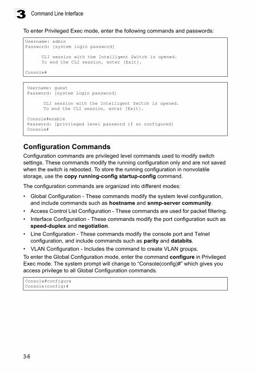
Command Line Interface
3-6
3To enter Privileged Exec mode, enter the following commands and passwords:
Configuration CommandsConfiguration commands are privileged level commands used to modify switch settings. These commands modify the running configuration only and are not saved when the switch is rebooted. To store the running configuration in nonvolatile storage, use the copy running-config startup-config command.
The configuration commands are organized into different modes:
• Global Configuration - These commands modify the system level configuration, and include commands such as hostname and snmp-server community.
• Access Control List Configuration - These commands are used for packet filtering.• Interface Configuration - These commands modify the port configuration such as
speed-duplex and negotiation. • Line Configuration - These commands modify the console port and Telnet
configuration, and include commands such as parity and databits.• VLAN Configuration - Includes the command to create VLAN groups.To enter the Global Configuration mode, enter the command configure in Privileged Exec mode. The system prompt will change to “Console(config)#” which gives you access privilege to all Global Configuration commands.
Username: adminPassword: [system login password]
CLI session with the Intelligent Switch is opened. To end the CLI session, enter [Exit].
Console#
Username: guestPassword: [system login password]
CLI session with the Intelligent Switch is opened. To end the CLI session, enter [Exit].
Console#enablePassword: [privileged level password if so configured]Console#
Console#configureConsole(config)#
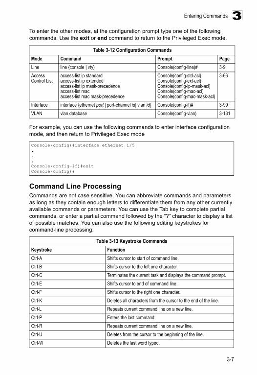
Entering Commands
3-7
3To enter the other modes, at the configuration prompt type one of the following commands. Use the exit or end command to return to the Privileged Exec mode.
For example, you can use the following commands to enter interface configuration mode, and then return to Privileged Exec mode
Command Line ProcessingCommands are not case sensitive. You can abbreviate commands and parameters as long as they contain enough letters to differentiate them from any other currently available commands or parameters. You can use the Tab key to complete partial commands, or enter a partial command followed by the “?” character to display a list of possible matches. You can also use the following editing keystrokes for command-line processing:
Table 3-12 Configuration CommandsMode Command Prompt PageLine line {console | vty} Console(config-line)# 3-9Access Control List
access-list ip standardaccess-list ip extendedaccess-list ip mask-precedenceaccess-list macaccess-list mac mask-precedence
Console(config-std-acl)Console(config-ext-acl)Console(config-ip-mask-acl)Console(config-mac-acl)Console(config-mac-mask-acl)
3-66
Interface interface {ethernet port | port-channel id| vlan id} Console(config-if)# 3-99VLAN vlan database Console(config-vlan) 3-131
Console(config)#interface ethernet 1/5...Console(config-if)#exitConsole(config)#
Table 3-13 Keystroke CommandsKeystroke FunctionCtrl-A Shifts cursor to start of command line. Ctrl-B Shifts cursor to the left one character.Ctrl-C Terminates the current task and displays the command prompt.Ctrl-E Shifts cursor to end of command line. Ctrl-F Shifts cursor to the right one character.Ctrl-K Deletes all characters from the cursor to the end of the line.Ctrl-L Repeats current command line on a new line.Ctrl-P Enters the last command.Ctrl-R Repeats current command line on a new line.Ctrl-U Deletes from the cursor to the beginning of the line. Ctrl-W Deletes the last word typed.
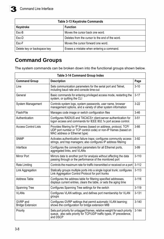
Command Line Interface
3-8
3
Command GroupsThe system commands can be broken down into the functional groups shown below.
Esc-B Moves the cursor back one word.Esc-D Deletes from the cursor to the end of the word.Esc-F Moves the cursor forward one word.Delete key or backspace key Erases a mistake when entering a command.
Table 3-14 Command Group IndexCommand Group Description PageLine Sets communication parameters for the serial port and Telnet,
including baud rate and console time-out3-10
General Basic commands for entering privileged access mode, restarting the system, or quitting the CLI
3-17
System Management Controls system logs, system passwords, user name, browser management options, and a variety of other system information
3-22
Flash/File Manages code image or switch configuration files 3-46Authentication Configures RADIUS and TACACS+ client-server authentication for
logon access and commands for IEEE 802.1x port access control.3-51
Access Control Lists Provides filtering for IP frames (based on address, protocol, TCP/UDP port number or TCP control code) or non-IP frames (based on MAC address or Ethernet type)
3-66
SNMP Activates authentication failure traps; configures community access strings, and trap managers; also configures IP address filtering
3-92
Interface Configures the connection parameters for all Ethernet ports, aggregated links, and VLANs
3-99
Mirror Port Mirrors data to another port for analysis without affecting the data passing through or the performance of the monitored port
3-110
Rate Limiting Controls the maximum rate for traffic transmitted or received on a port 3-112Link Aggregation Statically groups multiple ports into a single logical trunk; configures
Link Aggregation Control Protocol for port trunks3-113
Address Table Configures the address table for filtering specified addresses, displays current entries, clears the table, or sets the aging time
3-116
Spanning Tree Configures Spanning Tree settings for the switch 3-119VLANs Configures VLAN settings, and defines port membership for VLAN
groups3-131
GVRP and Bridge Extension
Configures GVRP settings that permit automatic VLAN learning; shows the configuration for bridge extension MIB
3-140
Priority Sets port priority for untagged frames, relative weight for each priority queue, also sets priority for TCP/UDP traffic types, IP precedence, and DSCP
3-144
Table 3-13 Keystroke CommandsKeystroke Function
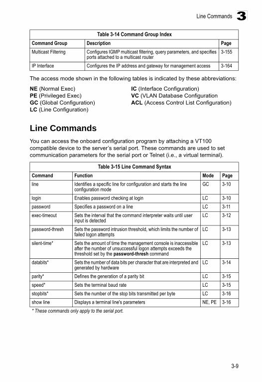
Line Commands
3-9
3
The access mode shown in the following tables is indicated by these abbreviations:
NE (Normal Exec) IC (Interface Configuration) PE (Privileged Exec) VC (VLAN Database ConfigurationGC (Global Configuration) ACL (Access Control List Configuration)LC (Line Configuration)
Line CommandsYou can access the onboard configuration program by attaching a VT100 compatible device to the server’s serial port. These commands are used to set communication parameters for the serial port or Telnet (i.e., a virtual terminal).
Multicast Filtering Configures IGMP multicast filtering, query parameters, and specifies ports attached to a multicast router
3-155
IP Interface Configures the IP address and gateway for management access 3-164
Table 3-15 Line Command SyntaxCommand Function Mode Pageline Identifies a specific line for configuration and starts the line
configuration modeGC 3-10
login Enables password checking at login LC 3-10password Specifies a password on a line LC 3-11exec-timeout Sets the interval that the command interpreter waits until user
input is detectedLC 3-12
password-thresh Sets the password intrusion threshold, which limits the number of failed logon attempts
LC 3-13
silent-time* Sets the amount of time the management console is inaccessible after the number of unsuccessful logon attempts exceeds the threshold set by the password-thresh command
LC 3-13
databits* Sets the number of data bits per character that are interpreted and generated by hardware
LC 3-14
parity* Defines the generation of a parity bit LC 3-15speed* Sets the terminal baud rate LC 3-15stopbits* Sets the number of the stop bits transmitted per byte LC 3-16show line Displays a terminal line's parameters NE, PE 3-16* These commands only apply to the serial port.
Table 3-14 Command Group IndexCommand Group Description Page
Command Line Interface
3-10
3lineUse this command to identify a specific line for configuration, and to process subsequent line configuration commands.
Syntax
line {console | vty}
• console - Console terminal line. • vty - Virtual terminal for remote console access (i.e., Telnet).
Default Setting
There is no default line.
Command Mode
Global Configuration
Command Usage
Telnet is considered a virtual terminal connection and will be shown as “Vty” in screen displays such as show users. However, the serial communication parameters (e.g., databits) do not affect Telnet connections.
Example
To enter console line mode, enter the following command:
Related Commands
show line (3-16)show users (3-44)
loginUse this command to enable password checking at login. Use the no form to disable password checking and allow connections without a password.
Syntax
login [local] no login
local - Selects local password checking. Authentication is based on the user name specified with the username command.
Default Setting
login local
Command Mode
Line Configuration
Console(config)#line consoleConsole(config-line)#
Line Commands
3-11
3Command Usage
• There are three authentication modes provided by the switch itself at login:• login selects authentication by a single global password as specified by the
password line configuration command. When using this method, the management interface starts in Normal Exec (NE) mode.
• login local selects authentication via the user name and password specified by the username command (i.e., default setting). When using this method, the management interface starts in Normal Exec (NE) or Privileged Exec (PE) mode, depending on the user’s privilege level (0 or 15 respectively).
• no login selects no authentication. When using this method, the management interface starts in Normal Exec (NE) mode.
• This command controls login authentication via the switch itself. To configure user names and passwords for remote authentication servers, you must use the RADIUS/TACACS software installed on those servers.
Example
Related Commands
username (3-24)password (3-11)
passwordUse this command to specify the password for a line. Use the no form to remove the password.
Syntax
password {0 | 7} passwordno password
- {0 | 7} - 0 means plain password, 7 means encrypted password- password - Character string that specifies the line password.
(Maximum length: 8 characters plain text, 32 encrypted, case sensitive)
Default Setting
No password is specified.
Command Mode
Line Configuration
Command Usage
• When a connection is started on a line with password protection, the system prompts for the password. If you enter the correct password, the system shows a prompt. You can use the password-thresh command to set the
Console(config-line)#login localConsole(config-line)#
Command Line Interface
3-12
3number of times a user can enter an incorrect password before the system terminates the line connection and returns the terminal to the idle state.
• The encrypted password is required for compatibility with legacy password settings (i.e., plain text or encrypted) when reading the configuration file during system bootup or when downloading the configuration file from a TFTP server. There is no need for you to manually configure encrypted passwords.
Example
Related Commands
login (3-10)password-thresh (3-13)
exec-timeoutUse this command to set the interval that the system waits until user input is detected. Use the no form to restore the default.
Syntax
exec-timeout secondsno exec-timeout
seconds - Integer that specifies the number of seconds. (Range: 0 - 65535 seconds; 0: no timeout)
Default Setting
CLI: No timeoutTelnet: 10 minutes
Command Mode
Line Configuration
Command Usage
• If user input is detected within the timeout interval, the session is kept open; otherwise the session is terminated.
• This command applies to both the local console and Telnet connections.• The timeout for Telnet cannot be disabled.
Example
To set the timeout to two minutes, enter this command:
Console(config-line)#password 0 secretConsole(config-line)#
Console(config-line)#exec-timeout 120Console(config-line)#
Line Commands
3-13
3password-threshUse this command to set the password intrusion threshold which limits the number of failed logon attempts. Use the no form to remove the threshold value.
Syntax
password-thresh [threshold]no password-thresh
threshold - The number of allowed password attempts. (Range: 1-120; 0: no threshold)
Default Setting
The default value is three attempts.
Command Mode
Line Configuration
Command Usage
• When the logon attempt threshold is reached, the system interface becomes silent for a specified amount of time before allowing the next logon attempt. (Use the silent-time command to set this interval.) When this threshold is reached for Telnet, the Telnet logon interface shuts down.
• This command applies to both the local console and Telnet connections.
Example
To set the password threshold to five attempts, enter this command:
Related Commands
silent-time (3-13)
silent-timeUse this command to set the amount of time the management console is inaccessible after the number of unsuccessful logon attempts exceeds the threshold set by the password-thresh command. Use the no form to remove the silent time value.
Syntax
silent-time secondsno silent-time
seconds - The number of seconds to disable console response. (Range: 0-65535; 0: no silent-time)
Console(config-line)#password-thresh 5Console(config-line)#
Command Line Interface
3-14
3Default Setting
The default value is no silent-time.
Command Mode
Line Configuration
Example
To set the silent time to 60 seconds, enter this command:
Related Commands
password-thresh (3-13)
databitsUse this command to set the number of data bits per character that are interpreted and generated by the console port. Use the no form to restore the default value.
Syntax databits {7 | 8}no databits
• 7 - Seven data bits per character. • 8 - Eight data bits per character.
Default Setting 8 data bits per character
Command Mode Line Configuration
Command Usage The databits command can be used to mask the high bit on input from devices that generate 7 data bits with parity. If parity is being generated, specify 7 data bits per character. If no parity is required, specify 8 data bits per character.
Example
To specify 7 data bits, enter this command:
Related Commands
parity (3-15)
Console(config-line)#silent-time 60Console(config-line)#
Console(config-line)#databits 7Console(config-line)#
Line Commands
3-15
3parityUse this command to define generation of a parity bit. Use the no form to restore the default setting.
Syntax
parity {none | even | odd}no parity
• none - No parity • even - Even parity • odd - Odd parity
Default Setting
No parity
Command Mode
Line Configuration
Command Usage
Communication protocols provided by devices such as terminals and modems often require a specific parity bit setting.
Example
To specify no parity, enter this command:
speedUse this command to set the terminal line's baud rate. This command sets both the transmit (to terminal) and receive (from terminal) speeds. Use the no form to restore the default setting.
Syntax
speed bpsno speed
bps - Baud rate in bits per second. (Options: 9600, 57600, 38400, 19200, 115200 bps)
Default Setting
9600 bps
Command Mode
Line Configuration
Console(config-line)#parity noneConsole(config-line)#
Command Line Interface
3-16
3Command Usage
Set the speed to match the baud rate of the device connected to the serial port. Some baud rates available on devices connected to the port might not be supported. The system indicates if the speed you selected is not supported.
Example
To specify 57600 bps, enter this command:
stopbitsUse this command to set the number of the stop bits transmitted per byte. Use the no form to restore the default setting.
Syntax stopbits {1 | 2}
• 1 - One stop bit • 2 - Two stop bits
Default Setting
1 stop bit
Command Mode
Line Configuration
Example
To specify 2 stop bits, enter this command:
show lineUse this command to display the terminal line's parameters.
Syntax
show line [console | vty]
• console - Console terminal line.• vty - Virtual terminal for remote console access.
Default Setting
Shows all lines
Command Mode
Normal Exec, Privileged Exec
Console(config-line)#speed 57600Console(config-line)#
Console(config-line)#stopbits 2Console(config-line)#
General Commands
3-17
3Example
To show all lines, enter this command:
General Commands
enableUse this command to activate Privileged Exec mode. In privileged mode, additional commands are available, and certain commands display additional information. See “Understanding Command Modes” on page 3-5.
Syntax
enable [level]
level - Privilege level to log into the device.
The device has two predefined privilege levels: 0: Normal Exec, 15: Privileged Exec. Enter level 15 to access Privileged Exec mode.
Console#show line Console configuration: Password threshold: 3 times Interactive timeout: Disabled Silent time: Disabled Baudrate: 9600 Databits: 8 Parity: none Stopbits: 1
Vty configuration: Password threshold: 3 times Interactive timeout: 65535Console#
Table 3-16 General CommandsCommand Function Mode Pageenable Activates privileged mode NE 3-17disable Returns to normal mode from privileged mode PE 3-18configure Activates global configuration mode PE 3-19show history Shows the contents of the command history buffer NE, PE 3-19reload Restarts the system PE 3-20end Returns to Privileged Exec mode any config.
mode 3-20
exit Returns to the previous configuration mode, or exits the CLI any 3-21quit Exits a CLI session NE, PE 3-21help Shows how to use help any NA? Shows options for command completion (context sensitive) any NA
Command Line Interface
3-18
3Default Setting
Level 15
Command Mode
Normal Exec
Command Usage
• “super” is the default password required to change the command mode from Normal Exec to Privileged Exec. (To set this password, see the enable password command on page 3-25.)
• The “#” character is appended to the end of the prompt to indicate that the system is in privileged access mode.
Example
Related Commands
disable (3-18)enable password (3-25)
disableUse this command to return to Normal Exec mode from privileged mode. In normal access mode, you can only display basic information on the switch's configuration or Ethernet statistics. To gain access to all commands, you must use the privileged mode. See “Understanding Command Modes” on page 3-5.
Default Setting
None
Command Mode
Privileged Exec
Command Usage
The “>” character is appended to the end of the prompt to indicate that the system is in normal access mode.
Example
Related Commands
enable (3-17)
Console> enablePassword: [privileged level password]Console#
Console#disableConsole>
General Commands
3-19
3configureUse this command to activate Global Configuration mode. You must enter this mode to modify any settings on the switch. You must also enter Global Configuration mode prior to enabling some of the other configuration modes, including Interface Configuration, Line Configuration, and VLAN Database Configuration. See “Understanding Command Modes” on page 3-5.
Default Setting
None
Command Mode
Privileged Exec
Example
Related Commands
end (3-20)
show historyUse this command to show the contents of the command history buffer.
Default Setting
None
Command Mode
Normal Exec, Privileged Exec
Command Usage
The history buffer size is fixed at 10 Execution commands and 10 Configuration commands.
Example
In this example, the show history command lists the contents of the command history buffer:
Console#configureConsole(config)#
Console#show historyExecution command history: 2 config 1 show history
Configuration command history: 4 interface vlan 1 3 exit 2 interface vlan 1 1 endConsole#
Command Line Interface
3-20
3The ! command repeats commands from the Execution command history buffer when you are in Normal Exec or Privileged Exec Mode, and commands from the Configuration command history buffer when you are in any of the configuration modes. In this example, the !2 command repeats the second command in the Execution history buffer (config).
reloadUse this command to restart the system.
Caution: When the system is restarted, it will always run the Power-On Self-Test. It will also retain all configuration information stored in non-volatile memory by the copy running-config startup-config command.
Default Setting
None
Command Mode
Privileged Exec
Command Usage
This command resets the entire system.
Example
This example shows how to reset the switch:
endUse this command to return to Privileged Exec mode.
Default Setting
None
Command Mode
Global Configuration, Interface Configuration, Line Configuration, VLAN Database Configuration
Example
This example shows how to return to the Privileged Exec mode from the Interface Configuration mode:
Console#!2Console#configConsole(config)#
Console#reloadSystem will be restarted, continue <y/n>? y
Console(config-if)#endConsole#
General Commands
3-21
3exitUse this command to return to the previous configuration mode or exit the configuration program.
Default Setting
None
Command Mode
Any
Example
This example shows how to return to the Privileged Exec mode from the Global Configuration mode, and then quit the CLI session:
quitUse this command to exit the configuration program.
Default Setting
None
Command Mode
Normal Exec, Privileged Exec
Command Usage
The quit and exit commands can both exit the configuration program.
Example
This example shows how to quit a CLI session:
Console(config)#exitConsole#exit
Press ENTER to start session
User Access Verification
Username:
Console#quit
Press ENTER to start session
User Access Verification
Username:
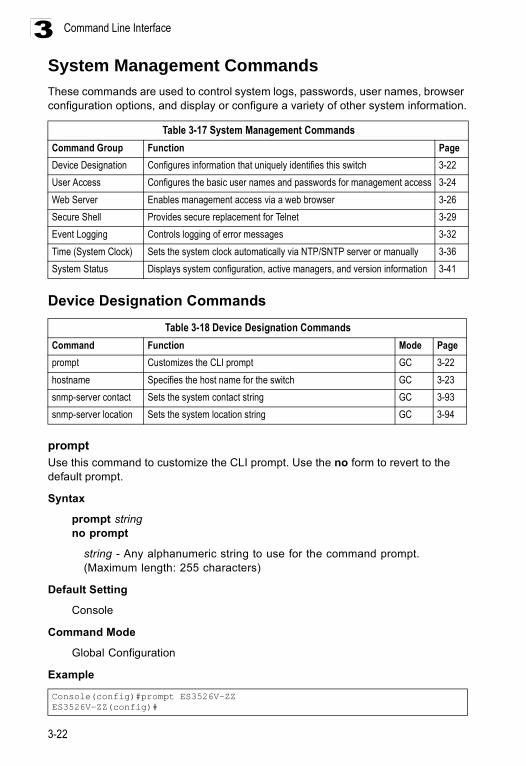
Command Line Interface
3-22
3System Management CommandsThese commands are used to control system logs, passwords, user names, browser configuration options, and display or configure a variety of other system information.
Device Designation Commands
promptUse this command to customize the CLI prompt. Use the no form to revert to the default prompt.
Syntax
prompt stringno prompt
string - Any alphanumeric string to use for the command prompt. (Maximum length: 255 characters)
Default Setting
Console
Command Mode
Global Configuration
Example
Table 3-17 System Management CommandsCommand Group Function PageDevice Designation Configures information that uniquely identifies this switch 3-22User Access Configures the basic user names and passwords for management access 3-24Web Server Enables management access via a web browser 3-26Secure Shell Provides secure replacement for Telnet 3-29Event Logging Controls logging of error messages 3-32Time (System Clock) Sets the system clock automatically via NTP/SNTP server or manually 3-36System Status Displays system configuration, active managers, and version information 3-41
Table 3-18 Device Designation CommandsCommand Function Mode Pageprompt Customizes the CLI prompt GC 3-22hostname Specifies the host name for the switch GC 3-23snmp-server contact Sets the system contact string GC 3-93snmp-server location Sets the system location string GC 3-94
Console(config)#prompt ES3526V-ZZES3526V-ZZ(config)#
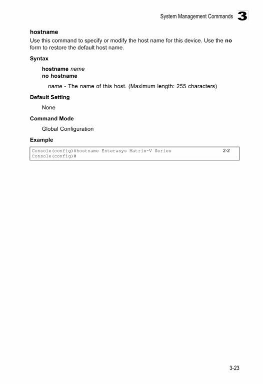
System Management Commands
3-23
3hostnameUse this command to specify or modify the host name for this device. Use the no form to restore the default host name.
Syntax
hostname nameno hostname
name - The name of this host. (Maximum length: 255 characters)
Default Setting
None
Command Mode
Global Configuration
Example
Console(config)#hostname Enterasys Matrix-V Series 2-2Console(config)#
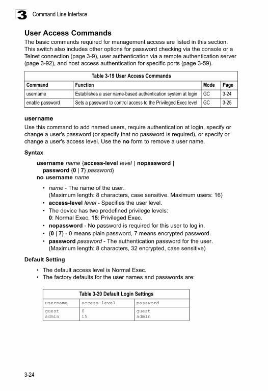
Command Line Interface
3-24
3User Access CommandsThe basic commands required for management access are listed in this section. This switch also includes other options for password checking via the console or a Telnet connection (page 3-9), user authentication via a remote authentication server (page 3-92), and host access authentication for specific ports (page 3-59).
usernameUse this command to add named users, require authentication at login, specify or change a user's password (or specify that no password is required), or specify or change a user's access level. Use the no form to remove a user name.
Syntax
username name {access-level level | nopassword | password {0 | 7} password}
no username name
• name - The name of the user. (Maximum length: 8 characters, case sensitive. Maximum users: 16)
• access-level level - Specifies the user level.• The device has two predefined privilege levels:
0: Normal Exec, 15: Privileged Exec. • nopassword - No password is required for this user to log in. • {0 | 7} - 0 means plain password, 7 means encrypted password. • password password - The authentication password for the user.
(Maximum length: 8 characters, 32 encrypted, case sensitive)
Default Setting
• The default access level is Normal Exec. • The factory defaults for the user names and passwords are:
Table 3-19 User Access CommandsCommand Function Mode Pageusername Establishes a user name-based authentication system at login GC 3-24enable password Sets a password to control access to the Privileged Exec level GC 3-25
Table 3-20 Default Login Settingsusername access-level password
guestadmin
0 15
guestadmin
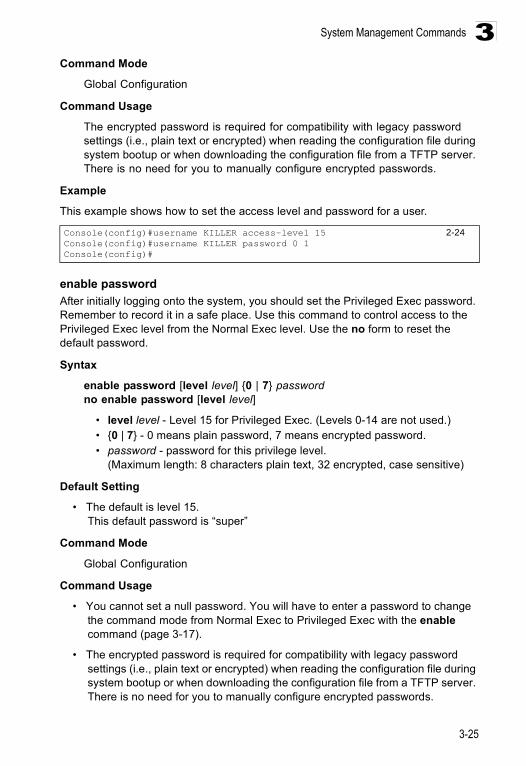
System Management Commands
3-25
3Command Mode
Global Configuration
Command Usage
The encrypted password is required for compatibility with legacy password settings (i.e., plain text or encrypted) when reading the configuration file during system bootup or when downloading the configuration file from a TFTP server. There is no need for you to manually configure encrypted passwords.
Example
This example shows how to set the access level and password for a user.
enable passwordAfter initially logging onto the system, you should set the Privileged Exec password. Remember to record it in a safe place. Use this command to control access to the Privileged Exec level from the Normal Exec level. Use the no form to reset the default password.
Syntax
enable password [level level] {0 | 7} passwordno enable password [level level]
• level level - Level 15 for Privileged Exec. (Levels 0-14 are not used.)• {0 | 7} - 0 means plain password, 7 means encrypted password. • password - password for this privilege level.
(Maximum length: 8 characters plain text, 32 encrypted, case sensitive)
Default Setting
• The default is level 15.This default password is “super”
Command Mode
Global Configuration
Command Usage
• You cannot set a null password. You will have to enter a password to change the command mode from Normal Exec to Privileged Exec with the enable command (page 3-17).
• The encrypted password is required for compatibility with legacy password settings (i.e., plain text or encrypted) when reading the configuration file during system bootup or when downloading the configuration file from a TFTP server. There is no need for you to manually configure encrypted passwords.
Console(config)#username KILLER access-level 15 2-24Console(config)#username KILLER password 0 1Console(config)#
Command Line Interface
3-26
3Example
Related Commands
enable (3-17)
Web Server Commands
ip http portUse this command to specify the TCP port number used by the Web browser interface. Use the no form to use the default port.
Syntax
ip http port port-numberno ip http port
port-number - The TCP port to be used by the browser interface. (Range: 1-65535)
Default Setting
80
Command Mode
Global Configuration
Example
Related Commands
ip http server (3-27)
Console(config)#enable password level 15 0 adminConsole(config)#
Table 3-21 Web Server CommandsCommand Function Mode Pageip http port Specifies the port to be used by the web browser interface GC 3-26ip http server Allows the switch to be monitored or configured from a browser GC 3-27ip http secure-server Enables HTTPS/SSL for encrypted communications GC 3-27ip http secure-port Specifies the UDP port number for HTTPS/SSL GC 3-28
Console(config)#ip http port 769Console(config)#
System Management Commands
3-27
3ip http serverUse this command to allow this device to be monitored or configured from a browser. Use the no form to disable this function.
Syntax
[no] ip http server
Default Setting
Enabled
Command Mode
Global Configuration
Example
Related Commands
ip http port (3-26)
ip http secure-serverThis command enables the secure hypertext transfer protocol (HTTPS) over the Secure Socket Layer (SSL), providing secure access (i.e., an encrypted connection) to the switch’s web interface. Use the no form to disable this function.
Syntax [no] ip http secure-server
Default Setting Enabled
Command Mode Global Configuration
Command Usage • Both HTTP and HTTPS service can be enabled independently on the switch.
However, you cannot configure the HTTP and HTTPS servers to use the same UDP port.
• If you enable HTTPS, you must indicate this in the URL that you specify in your browser: https://device[:port_number]
• When you start HTTPS, the connection is established in this way:- The client authenticates the server using the server’s digital certificate.- The client and server negotiate a set of security protocols to use for the
connection.- The client and server generate session keys for encrypting and decrypting
data.• The client and server establish a secure encrypted connection.
Console(config)#ip http serverConsole(config)#
Command Line Interface
3-28
3A padlock icon should appear in the status bar for Internet Explorer 5.x and Netscape Navigator 4.x or later versions.
• The following web browsers and operating systems currently support HTTPS:
• To specify a secure-site certificate, see “Replacing the Default Secure-site Certificate” on page 2-29. Also refer to the copy command on page 3-46.
Example
Related Commandsip http secure-port (3-28)copy tftp https-certificate (3-46)
ip http secure-portThis command specifies the UDP port number used for HTTPS/SSL connection to the switch’s web interface. Use the no form to restore the default port.
Syntax ip http secure-port port_numberno ip http secure-port
port_number – The UDP port used for HTTPS/SSL. (Range: 1-65535)
Default Setting 443
Command Mode Global Configuration
Command Usage • You cannot configure the HTTP and HTTPS servers to use the same port. • If you change the HTTPS port number, clients attempting to connect to the
HTTPS server must specify the port number in the URL, in this format:https://device:port_number
Example
Table 3-22 Web Browser Table 3-23 Operating SystemInternet Explorer 5.0 or later Windows 98,Windows NT (with service pack 6a),
Windows 2000, Windows XPNetscape Navigator 4.76 or later Windows 98,Windows NT (with service pack 6a),
Windows 2000, Windows XP, Solaris 2.6
Console(config)#ip http secure-serverConsole(config)#
Console(config)#ip http secure-port 1000Console(config)#
System Management Commands
3-29
3Related Commands
ip http secure-server (3-27)
Secure Shell Commands The Berkley-standard includes remote access tools originally designed for Unix systems. Some of these tools have also been implemented for Microsoft Windows and other environments. These tools, including commands such as rlogin (remote login), rsh (remote shell), and rcp (remote copy), are not secure from hostile attacks.
The Secure Shell (SSH) includes server/client applications intended as a secure replacement for the older Berkley remote access tools. SSH can also provide remote management access to this switch as a secure replacement for Telnet. When a client contacts the switch via the SSH protocol, the switch uses a public-key that the client must match along with a local user name and password for access authentication.
This section describes the commands used to configure the SSH server. However, note that you also need to install a SSH client on the management station when using this protocol to configure the switch.
Note: The switch supports only SSH Version 1.5.
ip ssh serverUse this command to enable the Secure Shell (SSH) server on this switch. Use the no form to disable this service.
Syntax ip ssh serverno ip ssh server
Default Setting Disabled
Command Mode Global Configuration
Table 3-24 Secure Shell CommandsCommand Function Mode Pageip ssh server Enables the SSH server on the switch GC 3-29ip ssh timeout Specifies the authentication timeout for the SSH server GC 3-30ip ssh authentication-retries
Specifies the number of retries allowed by a client GC 3-31
show ip ssh Displays the status of the SSH server and the configured values for authentication timeout and retries
PE 3-31
disconnect ssh Terminates an SSH connection PE 3-31show ssh Displays the status of current SSH sessions PE 3-32
Command Line Interface
3-30
3Command Usage
• The SSH server supports up to four client sessions. The maximum number of client sessions includes both current Telnet sessions and SSH sessions.
• The SSH server uses RSA for key exchange when the client first establishes a connection with the switch, and then negotiates with the client to select either DES (56-bit) or 3DES (168-bit) for data encryption.
Example
Related Commandsshow ssh (3-32)
ip ssh timeoutUse this command to configure the timeout for the SSH server. Use the no form to restore the default setting.
Syntax ip ssh timeout secondsno ip ssh timeout
seconds – The timeout for client response during SSH negotiation. (Range: 1-120)
Default Setting 10 seconds
Command Mode Global Configuration
Command Usage The timeout specifies the interval the switch will wait for a response from the client during the SSH negotiation phase. Once an SSH session has been established, the timeout for user input is controlled by the exec-timeout command for vty sessions.
Example
Related Commandsexec-timeout (3-12)show ip ssh (3-31)
Console(config)#ip ssh serverConsole(config)#
Console(config)#ip ssh timeout 60Console(config)#
System Management Commands
3-31
3ip ssh authentication-retriesUse this command to configure the number of times the SSH server attempts to reauthenticate a user. Use the no form to restore the default setting.
Syntax ip ssh authentication-retries countno ip ssh authentication-retries
count – The number of authentication attempts permitted after which the interface is reset. (Range: 1-5)
Default Setting 3
Command Mode Global Configuration
Example
Related Commandsshow ip ssh (3-31)
show ip sshUse this command to display the connection settings used when authenticating client access to the Secure Shell (SSH) server.
Command Mode Privileged Exec
Example
disconnect sshUse this command to terminate a Secure Shell (SSH) client connection.
Syntax disconnect ssh connection-id
connection-id – The session identifier as displayed in the show ip ssh command.
Command Mode Privileged Exec
Console(config)#ip ssh authentication-retires 2Console(config)#
Console#show ip sshInformation of secure shellSSH status: enableSSH authentication timeout: 120SSH authentication retries: 3Console#
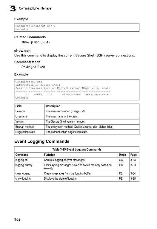
Command Line Interface
3-32
3Example
Related Commandsshow ip ssh (3-31)
show sshUse this command to display the current Secure Shell (SSH) server connections.
Command Mode Privileged Exec
Example
Event Logging Commands
Console#disconnect ssh 0Console#
Console#show sshInformation of secure shellSession Username Version Encrypt method Negotiation state------- -------- ------- -------------- ----------------- 0 admin 1.5 cipher-3des session-startedConsole#
Field DescriptionSession The session number. (Range: 0-3)Username The user name of the client.Version The Secure Shell version number.Encrypt method The encryption method. (Options: cipher-des, cipher-3des)Negotiation state The authentication negotiation state.
Table 3-25 Event Logging CommandsCommand Function Mode Pagelogging on Controls logging of error messages GC 3-33logging history Limits syslog messages saved to switch memory based on
severity GC 3-33
clear logging Clears messages from the logging buffer PE 3-34show logging Displays the state of logging PE 3-35
System Management Commands
3-33
3logging onThis command controls logging of error messages, sending debug or error messages to switch memory. The no form disables the logging process.
Syntax
[no] logging on
Default Setting
None
Command Mode
Global Configuration
Command Usage
The logging process controls error messages saved to switch memory. You can use the logging history command to control the type of error messages that are stored.
Example
Related Commands
logging history (3-33)clear logging (3-34)
logging historyUse this command to limit syslog messages saved to switch memory based on severity. The no form returns the logging of syslog messages to the default level.
Syntax
logging history {flash | ram} levelno logging history {flash | ram}
• flash - Event history stored in flash memory (i.e., permanent memory). • ram - Event history stored in temporary RAM (i.e., memory flushed on
power reset).
Console(config)#logging onConsole(config)#
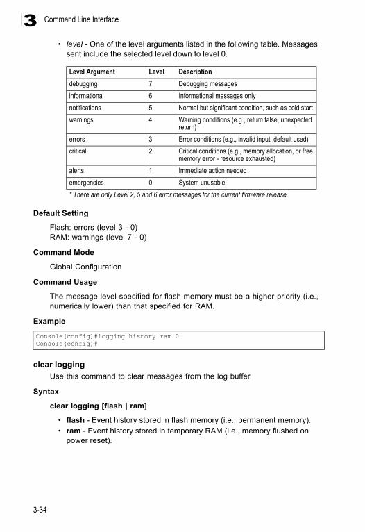
Command Line Interface
3-34
3• level - One of the level arguments listed in the following table. Messages
sent include the selected level down to level 0.
Default Setting
Flash: errors (level 3 - 0)RAM: warnings (level 7 - 0)
Command Mode
Global Configuration
Command Usage
The message level specified for flash memory must be a higher priority (i.e., numerically lower) than that specified for RAM.
Example
clear loggingUse this command to clear messages from the log buffer.
Syntax
clear logging [flash | ram]
• flash - Event history stored in flash memory (i.e., permanent memory). • ram - Event history stored in temporary RAM (i.e., memory flushed on
power reset).
Level Argument Level Descriptiondebugging 7 Debugging messagesinformational 6 Informational messages onlynotifications 5 Normal but significant condition, such as cold start warnings 4 Warning conditions (e.g., return false, unexpected
return)errors 3 Error conditions (e.g., invalid input, default used)critical 2 Critical conditions (e.g., memory allocation, or free
memory error - resource exhausted)alerts 1 Immediate action neededemergencies 0 System unusable* There are only Level 2, 5 and 6 error messages for the current firmware release.
Console(config)#logging history ram 0Console(config)#
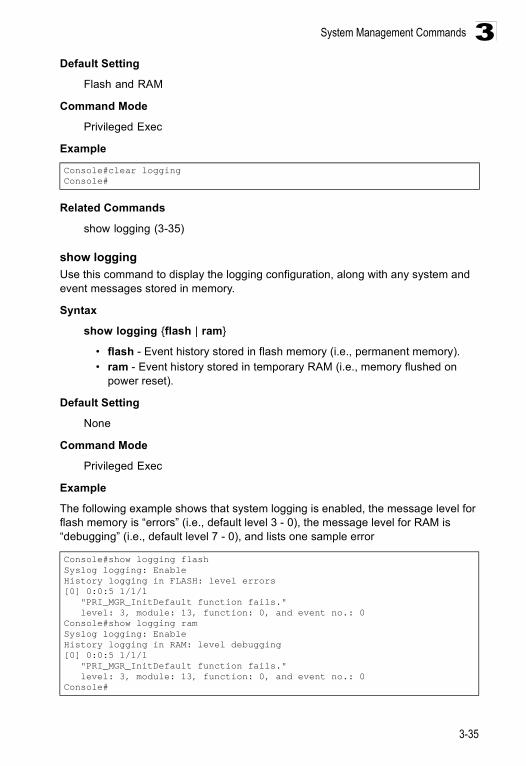
System Management Commands
3-35
3Default Setting
Flash and RAM
Command Mode
Privileged Exec
Example
Related Commands
show logging (3-35)
show loggingUse this command to display the logging configuration, along with any system and event messages stored in memory.
Syntax
show logging {flash | ram}
• flash - Event history stored in flash memory (i.e., permanent memory). • ram - Event history stored in temporary RAM (i.e., memory flushed on
power reset).
Default Setting
None
Command Mode
Privileged Exec
Example
The following example shows that system logging is enabled, the message level for flash memory is “errors” (i.e., default level 3 - 0), the message level for RAM is “debugging” (i.e., default level 7 - 0), and lists one sample error
Console#clear loggingConsole#
Console#show logging flashSyslog logging: EnableHistory logging in FLASH: level errors[0] 0:0:5 1/1/1 "PRI_MGR_InitDefault function fails." level: 3, module: 13, function: 0, and event no.: 0Console#show logging ramSyslog logging: EnableHistory logging in RAM: level debugging[0] 0:0:5 1/1/1 "PRI_MGR_InitDefault function fails." level: 3, module: 13, function: 0, and event no.: 0Console#
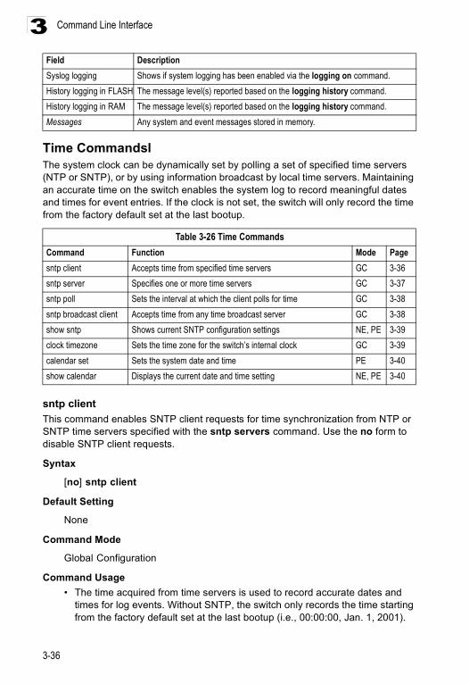
Command Line Interface
3-36
3
Time Commandsl The system clock can be dynamically set by polling a set of specified time servers (NTP or SNTP), or by using information broadcast by local time servers. Maintaining an accurate time on the switch enables the system log to record meaningful dates and times for event entries. If the clock is not set, the switch will only record the time from the factory default set at the last bootup.
sntp clientThis command enables SNTP client requests for time synchronization from NTP or SNTP time servers specified with the sntp servers command. Use the no form to disable SNTP client requests.
Syntax
[no] sntp client
Default Setting
None
Command Mode
Global Configuration
Command Usage • The time acquired from time servers is used to record accurate dates and
times for log events. Without SNTP, the switch only records the time starting from the factory default set at the last bootup (i.e., 00:00:00, Jan. 1, 2001).
Field DescriptionSyslog logging Shows if system logging has been enabled via the logging on command.History logging in FLASH The message level(s) reported based on the logging history command.History logging in RAM The message level(s) reported based on the logging history command.Messages Any system and event messages stored in memory.
Table 3-26 Time CommandsCommand Function Mode Pagesntp client Accepts time from specified time servers GC 3-36sntp server Specifies one or more time servers GC 3-37sntp poll Sets the interval at which the client polls for time GC 3-38sntp broadcast client Accepts time from any time broadcast server GC 3-38show sntp Shows current SNTP configuration settings NE, PE 3-39clock timezone Sets the time zone for the switch’s internal clock GC 3-39calendar set Sets the system date and time PE 3-40show calendar Displays the current date and time setting NE, PE 3-40
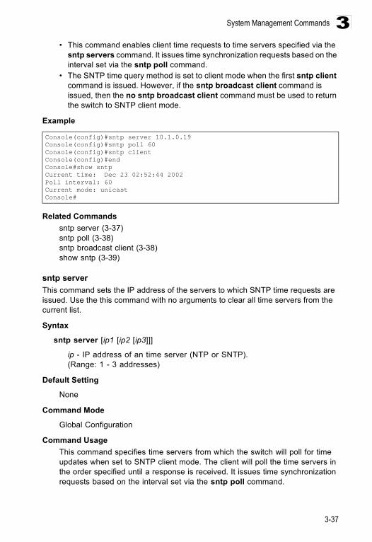
System Management Commands
3-37
3• This command enables client time requests to time servers specified via the
sntp servers command. It issues time synchronization requests based on the interval set via the sntp poll command.
• The SNTP time query method is set to client mode when the first sntp client command is issued. However, if the sntp broadcast client command is issued, then the no sntp broadcast client command must be used to return the switch to SNTP client mode.
Example
Related Commandssntp server (3-37)sntp poll (3-38)sntp broadcast client (3-38)show sntp (3-39)
sntp serverThis command sets the IP address of the servers to which SNTP time requests are issued. Use the this command with no arguments to clear all time servers from the current list.
Syntax
sntp server [ip1 [ip2 [ip3]]]
ip - IP address of an time server (NTP or SNTP). (Range: 1 - 3 addresses)
Default Setting
None
Command Mode
Global Configuration
Command Usage This command specifies time servers from which the switch will poll for time updates when set to SNTP client mode. The client will poll the time servers in the order specified until a response is received. It issues time synchronization requests based on the interval set via the sntp poll command.
Console(config)#sntp server 10.1.0.19Console(config)#sntp poll 60Console(config)#sntp clientConsole(config)#endConsole#show sntpCurrent time: Dec 23 02:52:44 2002Poll interval: 60Current mode: unicastConsole#
Command Line Interface
3-38
3Example
sntp pollThis command sets the interval between sending time requests when the switch is set to SNTP client mode. Use the no form to restore to the default.
Syntax
sntp poll secondsno sntp poll
seconds - Interval between time requests. (Range: 16-16384 seconds)
Default Setting
16 seconds
Command Mode
Global Configuration
Command Usage This command is only applicable when the switch is set to SNTP client mode.
Example
Related Commandssntp client (3-36)
sntp broadcast clientThis command synchronizes the switch’s clock based on time broadcast from time servers (using the multicast address 224.0.1.1). Use the no form to disable SNTP broadcast client mode.
Syntax
[no] sntp broadcast client
Default Setting
Disabled
Command Mode
Global Configuration
Console(config)#sntp server 10.1.0.19Console(config)#
Console(config)#sntp poll 250Console(config)#
System Management Commands
3-39
3Example
show sntpThis command displays the current time and configuration settings for the SNTP client, and indicates whether or not the local time has been properly updated.
Command Mode
Normal Exec, Privileged Exec
Example
clock timezoneThis command sets the time zone for the switch’s internal clock.
Syntax
clock timezone name hour hours minute minutes {before-utc | after-utc}
• name - Name of timezone, usually an acronym. (Range: 1-29 characters)• hours - Number of hours before/after UTC. (Range: 1-12 hours)• minutes - Number of minutes before/after UTC. (Range: 0-59 minutes)• before-utc - Sets the local time zone before (east) of UTC.• after-utc - Sets the local time zone after (west) of UTC.
Default Setting
None
Command Mode
Global Configuration
Example
Related Commandsshow sntp (3-39)
Console(config)#sntp broadcast clientConsole(config)#
Console#show sntpCurrent time: Dec 5 00:04:52 2002 ñóPoll interval: 16Current mode: unicastConsole#
Console#clock timezone Taipei hours 7 minute 00 after-UTCConsole#
Command Line Interface
3-40
3calendar set
Use this command to set the date and time of the system clock.
Syntax
calendar set hour min sec {month day year | day month year}
• hour - Hour in 24-hour format. (Range: 0 - 23)• min - Minute. (Range: 0 - 59)• sec - Second. (Range: 0 - 59)• month - january | february | march | april | may | june | july | august |
september | october | november | december • day - Day of month. (Range: 1 - 31)• year - Year (4-digit). (Range: 2001 - 2101)
Default Setting
None
Command Mode
Privileged Exec
Example
This example shows how to set the system clock to 15:12:34, March 21st, 2003.
show calendarUse this command to display the system clock.
Default Setting
None
Command Mode
Normal Exec, Privileged Exec
Example
This example shows how to display the current system clock setting.
Console#calendar set 15 12 34 March 21 2003Console#
Console#show calendar15:12:50 March 21 2003Console#
System Management Commands
3-41
3System Status Commands
show startup-configUse this command to display the configuration file stored in non-volatile memory that is used to start up the system.
Default Setting
None
Command Mode
Privileged Exec
Command Usage
• Use this command in conjunction with the show running-config command to compare the information in running memory to the information stored in non-volatile memory.
• This command displays settings for key command modes. Each mode group is separated by “!” symbols, and includes the configuration mode command, and corresponding commands. This command displays the following information:
- SNMP community strings- Users (names and access levels)- VLAN database (VLAN ID, name and state)- VLAN configuration settings for each interface- IP address configured for VLANs- Spanning tree settings- Any configured settings for the console port and Telnet
Table 3-27 System Status CommandsCommand Function Mode Pageshow startup-config Displays the contents of the configuration file (stored in flash
memory) that is used to start up the systemPE 3-41
show running-config Displays the configuration data currently in use PE 3-42show system Displays system information NE, PE 3-44show users Shows all active console and Telnet sessions, including user
name, idle time, and IP address of Telnet clientsNE, PE 3-44
show version Displays version information for the system NE, PE 3-45
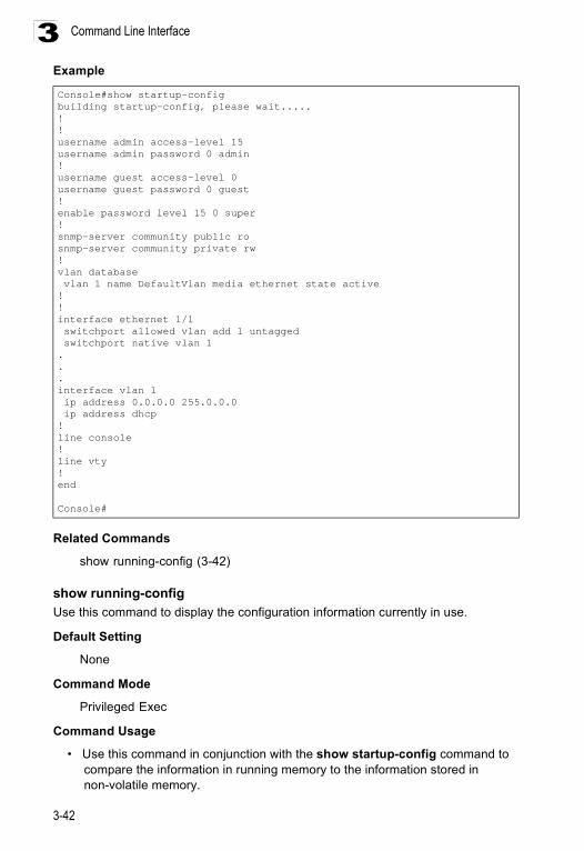
Command Line Interface
3-42
3Example
Related Commands
show running-config (3-42)
show running-configUse this command to display the configuration information currently in use.
Default Setting
None
Command Mode
Privileged Exec
Command Usage
• Use this command in conjunction with the show startup-config command to compare the information in running memory to the information stored in non-volatile memory.
Console#show startup-configbuilding startup-config, please wait.....!!username admin access-level 15username admin password 0 admin!username guest access-level 0username guest password 0 guest!enable password level 15 0 super!snmp-server community public rosnmp-server community private rw!vlan database vlan 1 name DefaultVlan media ethernet state active!!interface ethernet 1/1 switchport allowed vlan add 1 untagged switchport native vlan 1...interface vlan 1 ip address 0.0.0.0 255.0.0.0 ip address dhcp!line console!line vty!end
Console#
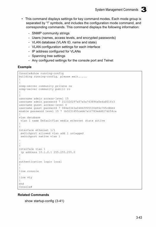
System Management Commands
3-43
3• This command displays settings for key command modes. Each mode group is
separated by “!” symbols, and includes the configuration mode command, and corresponding commands. This command displays the following information:
- SNMP community strings- Users (names, access levels, and encrypted passwords)- VLAN database (VLAN ID, name and state)- VLAN configuration settings for each interface- IP address configured for VLANs- Spanning tree settings- Any configured settings for the console port and Telnet
Example
Related Commands
show startup-config (3-41)
Console#show running-configbuilding running-config, please wait.....!!snmp-server community private rwsnmp-server community public ro!!username admin access-level 15username admin password 7 21232f297a57a5a743894a0e4a801fc3username guest access-level 0username guest password 7 084e0343a0486ff05530df6c705c8bb4enable password level 15 7 1b3231655cebb7a1f783eddf27d254ca!vlan database vlan 1 name DefaultVlan media ethernet state active!!interface ethernet 1/1 switchport allowed vlan add 1 untagged switchport native vlan 1..!interface vlan 1 ip address 10.1.0.1 255.255.255.0!!authentication login local!!line console!line vty!endConsole#
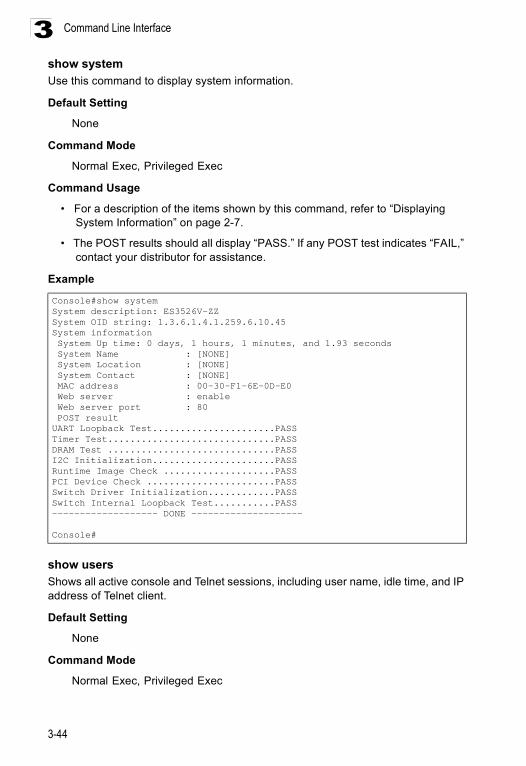
Command Line Interface
3-44
3show systemUse this command to display system information.
Default Setting
None
Command Mode
Normal Exec, Privileged Exec
Command Usage
• For a description of the items shown by this command, refer to “Displaying System Information” on page 2-7.
• The POST results should all display “PASS.” If any POST test indicates “FAIL,” contact your distributor for assistance.
Example
show usersShows all active console and Telnet sessions, including user name, idle time, and IP address of Telnet client.
Default Setting
None
Command Mode
Normal Exec, Privileged Exec
Console#show systemSystem description: ES3526V-ZZSystem OID string: 1.3.6.1.4.1.259.6.10.45System information System Up time: 0 days, 1 hours, 1 minutes, and 1.93 seconds System Name : [NONE] System Location : [NONE] System Contact : [NONE] MAC address : 00-30-F1-6E-0D-E0 Web server : enable Web server port : 80 POST resultUART Loopback Test......................PASSTimer Test..............................PASSDRAM Test ..............................PASSI2C Initialization......................PASSRuntime Image Check ....................PASSPCI Device Check .......................PASSSwitch Driver Initialization............PASSSwitch Internal Loopback Test...........PASS------------------- DONE --------------------
Console#
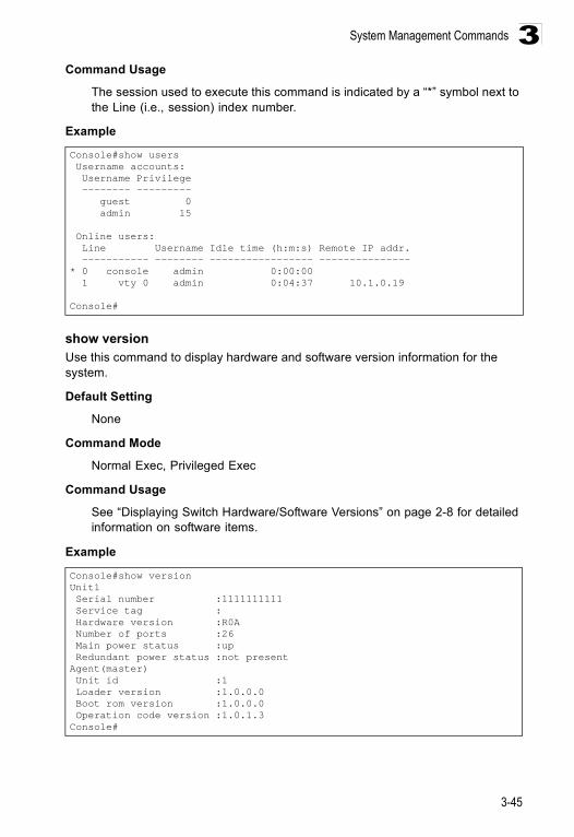
System Management Commands
3-45
3Command Usage
The session used to execute this command is indicated by a “*” symbol next to the Line (i.e., session) index number.
Example
show versionUse this command to display hardware and software version information for the system.
Default Setting
None
Command Mode
Normal Exec, Privileged Exec
Command Usage
See “Displaying Switch Hardware/Software Versions” on page 2-8 for detailed information on software items.
Example
Console#show users Username accounts: Username Privilege -------- --------- guest 0 admin 15
Online users: Line Username Idle time (h:m:s) Remote IP addr. ----------- -------- ----------------- ---------------* 0 console admin 0:00:00 1 vty 0 admin 0:04:37 10.1.0.19
Console#
Console#show versionUnit1 Serial number :1111111111 Service tag : Hardware version :R0A Number of ports :26 Main power status :up Redundant power status :not presentAgent(master) Unit id :1 Loader version :1.0.0.0 Boot rom version :1.0.0.0 Operation code version :1.0.1.3Console#
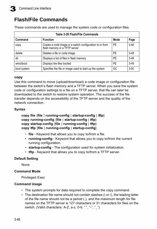
Command Line Interface
3-46
3Flash/File CommandsThese commands are used to manage the system code or configuration files.
copy Use this command to move (upload/download) a code image or configuration file between the switch’s flash memory and a TFTP server. When you save the system code or configuration settings to a file on a TFTP server, that file can later be downloaded to the switch to restore system operation. The success of the file transfer depends on the accessibility of the TFTP server and the quality of the network connection.
Syntax
copy file {file | running-config | startup-config | tftp}copy running-config {file | startup-config | tftp}copy startup-config {file | running-config | tftp}copy tftp {file | running-config | startup-config}
• file - Keyword that allows you to copy to/from a file. • running-config - Keyword that allows you to copy to/from the current
running configuration. • startup-config - The configuration used for system initialization. • tftp - Keyword that allows you to copy to/from a TFTP server.
Default Setting
None
Command Mode
Privileged Exec
Command Usage
• The system prompts for data required to complete the copy command. • The destination file name should not contain slashes (\ or /), the leading letter
of the file name should not be a period (.), and the maximum length for file names on the TFTP server is 127 characters or 31 characters for files on the switch. (Valid characters: A-Z, a-z, 0-9, “.”, “-”, “_”)
Table 3-28 Flash/File CommandsCommand Function Mode Pagecopy Copies a code image or a switch configuration to or from
flash memory or a TFTP serverPE 3-46
delete Deletes a file or code image PE 3-48dir Displays a list of files in flash memory PE 3-48whichboot Displays the files booted PE 3-49boot system Specifies the file or image used to start up the system GC 3-50
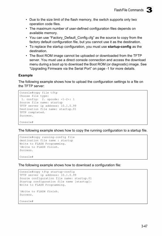
Flash/File Commands
3-47
3• Due to the size limit of the flash memory, the switch supports only two
operation code files.• The maximum number of user-defined configuration files depends on
available memory.• You can use “Factory_Default_Config.cfg” as the source to copy from the
factory default configuration file, but you cannot use it as the destination. • To replace the startup configuration, you must use startup-config as the
destination. • The Boot ROM image cannot be uploaded or downloaded from the TFTP
server. You must use a direct console connection and access the download menu during a boot up to download the Boot ROM (or diagnostic) image. See “Upgrading Firmware via the Serial Port” on page -1 for more details.
Example
The following example shows how to upload the configuration settings to a file on the TFTP server:
The following example shows how to copy the running configuration to a startup file.
The following example shows how to download a configuration file:
Console#copy file tftpChoose file type: 1. config: 2. opcode: <1-2>: 1Source file name: startupTFTP server ip address: 10.1.0.99Destination file name: startup.01TFTP completed.Success.
Console#
Console#copy running-config filedestination file name : startupWrite to FLASH Programming.\Write to FLASH finish.Success.
Console#
Console#copy tftp startup-configTFTP server ip address: 10.1.0.99Source configuration file name: startup.01Startup configuration file name [startup]:Write to FLASH Programming.
\Write to FLASH finish.Success.
Console#
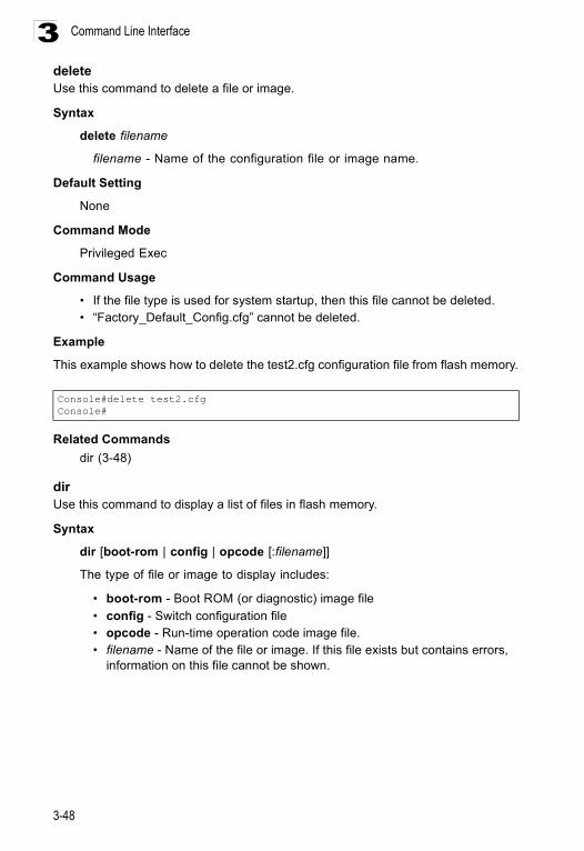
Command Line Interface
3-48
3deleteUse this command to delete a file or image.
Syntax
delete filename
filename - Name of the configuration file or image name.
Default Setting
None
Command Mode
Privileged Exec
Command Usage
• If the file type is used for system startup, then this file cannot be deleted. • “Factory_Default_Config.cfg” cannot be deleted.
Example
This example shows how to delete the test2.cfg configuration file from flash memory.
Related Commandsdir (3-48)
dirUse this command to display a list of files in flash memory.
Syntax
dir [boot-rom | config | opcode [:filename]]
The type of file or image to display includes:
• boot-rom - Boot ROM (or diagnostic) image file• config - Switch configuration file • opcode - Run-time operation code image file. • filename - Name of the file or image. If this file exists but contains errors,
information on this file cannot be shown.
Console#delete test2.cfgConsole#
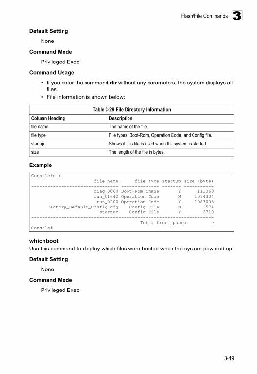
Flash/File Commands
3-49
3Default Setting
None
Command Mode
Privileged Exec
Command Usage
• If you enter the command dir without any parameters, the system displays all files.
• File information is shown below:
Example
whichbootUse this command to display which files were booted when the system powered up.
Default Setting
None
Command Mode
Privileged Exec
Table 3-29 File Directory InformationColumn Heading Descriptionfile name The name of the file.file type File types: Boot-Rom, Operation Code, and Config file.startup Shows if this file is used when the system is started.size The length of the file in bytes.
Console#dir file name file type startup size (byte)-------------------------------- -------------- ------- ----------- diag_0060 Boot-Rom image Y 111360 run_01642 Operation Code N 1074304 run_0200 Operation Code Y 1083008 Factory_Default_Config.cfg Config File N 2574 startup Config File Y 2710------------------------------------------------------------------- Total free space: 0Console#
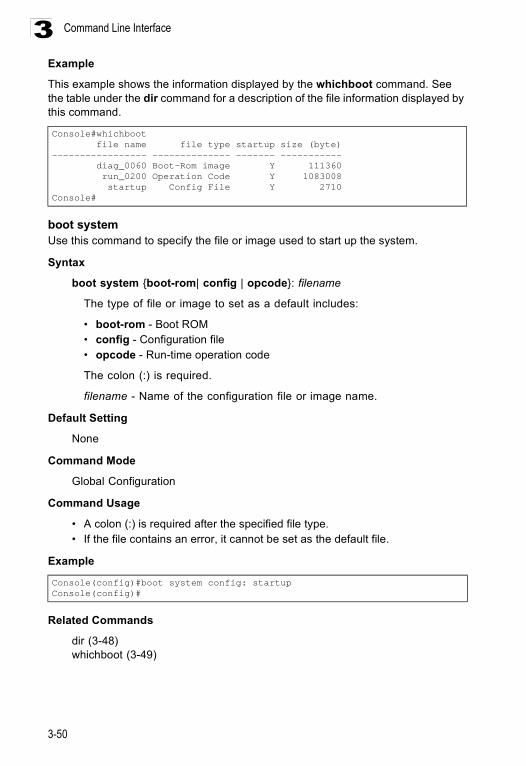
Command Line Interface
3-50
3Example
This example shows the information displayed by the whichboot command. See the table under the dir command for a description of the file information displayed by this command.
boot systemUse this command to specify the file or image used to start up the system.
Syntax
boot system {boot-rom| config | opcode}: filename
The type of file or image to set as a default includes:
• boot-rom - Boot ROM • config - Configuration file • opcode - Run-time operation code
The colon (:) is required.
filename - Name of the configuration file or image name.
Default Setting
None
Command Mode
Global Configuration
Command Usage
• A colon (:) is required after the specified file type. • If the file contains an error, it cannot be set as the default file.
Example
Related Commands
dir (3-48)whichboot (3-49)
Console#whichboot file name file type startup size (byte)----------------- -------------- ------- ----------- diag_0060 Boot-Rom image Y 111360 run_0200 Operation Code Y 1083008 startup Config File Y 2710Console#
Console(config)#boot system config: startupConsole(config)#
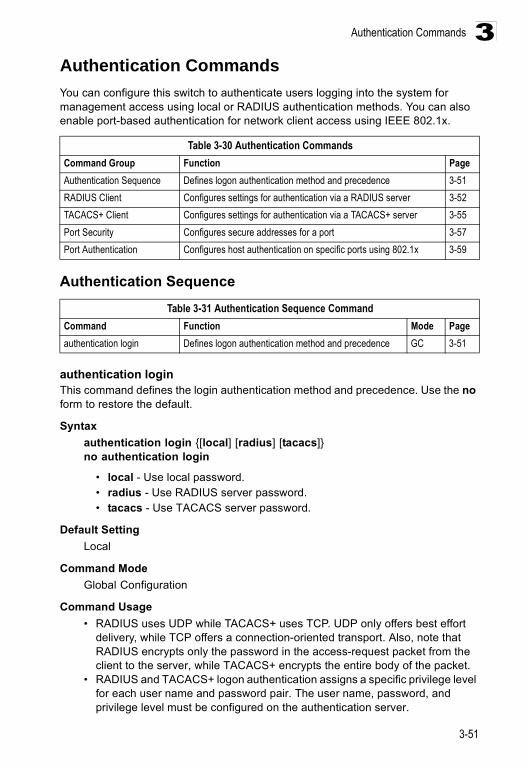
Authentication Commands
3-51
3Authentication Commands You can configure this switch to authenticate users logging into the system for management access using local or RADIUS authentication methods. You can also enable port-based authentication for network client access using IEEE 802.1x.
Authentication Sequence
authentication loginThis command defines the login authentication method and precedence. Use the no form to restore the default.
Syntax authentication login {[local] [radius] [tacacs]}no authentication login
• local - Use local password. • radius - Use RADIUS server password. • tacacs - Use TACACS server password.
Default Setting Local
Command Mode Global Configuration
Command Usage • RADIUS uses UDP while TACACS+ uses TCP. UDP only offers best effort
delivery, while TCP offers a connection-oriented transport. Also, note that RADIUS encrypts only the password in the access-request packet from the client to the server, while TACACS+ encrypts the entire body of the packet.
• RADIUS and TACACS+ logon authentication assigns a specific privilege level for each user name and password pair. The user name, password, and privilege level must be configured on the authentication server.
Table 3-30 Authentication CommandsCommand Group Function PageAuthentication Sequence Defines logon authentication method and precedence 3-51RADIUS Client Configures settings for authentication via a RADIUS server 3-52TACACS+ Client Configures settings for authentication via a TACACS+ server 3-55Port Security Configures secure addresses for a port 3-57Port Authentication Configures host authentication on specific ports using 802.1x 3-59
Table 3-31 Authentication Sequence CommandCommand Function Mode Pageauthentication login Defines logon authentication method and precedence GC 3-51
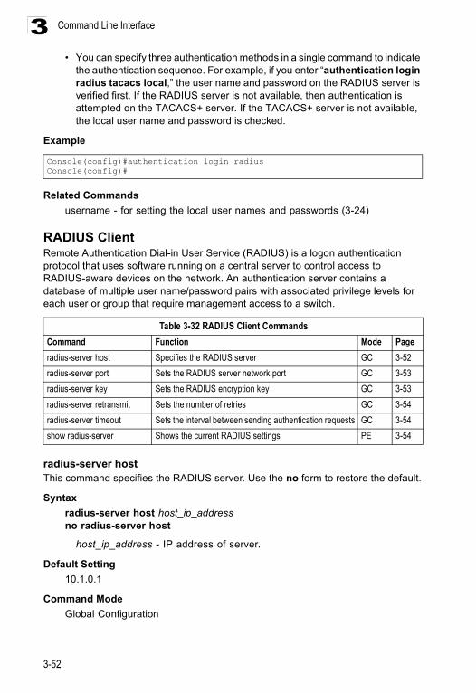
Command Line Interface
3-52
3• You can specify three authentication methods in a single command to indicate
the authentication sequence. For example, if you enter “authentication login radius tacacs local,” the user name and password on the RADIUS server is verified first. If the RADIUS server is not available, then authentication is attempted on the TACACS+ server. If the TACACS+ server is not available, the local user name and password is checked.
Example
Related Commandsusername - for setting the local user names and passwords (3-24)
RADIUS Client Remote Authentication Dial-in User Service (RADIUS) is a logon authentication protocol that uses software running on a central server to control access to RADIUS-aware devices on the network. An authentication server contains a database of multiple user name/password pairs with associated privilege levels for each user or group that require management access to a switch.
radius-server hostThis command specifies the RADIUS server. Use the no form to restore the default.
Syntax radius-server host host_ip_addressno radius-server host
host_ip_address - IP address of server.
Default Setting 10.1.0.1
Command Mode Global Configuration
Console(config)#authentication login radiusConsole(config)#
Table 3-32 RADIUS Client CommandsCommand Function Mode Pageradius-server host Specifies the RADIUS server GC 3-52radius-server port Sets the RADIUS server network port GC 3-53radius-server key Sets the RADIUS encryption key GC 3-53radius-server retransmit Sets the number of retries GC 3-54radius-server timeout Sets the interval between sending authentication requests GC 3-54show radius-server Shows the current RADIUS settings PE 3-54
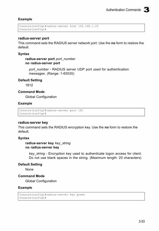
Authentication Commands
3-53
3Example
radius-server portThis command sets the RADIUS server network port. Use the no form to restore the default.
Syntax radius-server port port_numberno radius-server port
port_number - RADIUS server UDP port used for authentication messages. (Range: 1-65535)
Default Setting 1812
Command Mode Global Configuration
Example
radius-server keyThis command sets the RADIUS encryption key. Use the no form to restore the default.
Syntax radius-server key key_stringno radius-server key
key_string - Encryption key used to authenticate logon access for client. Do not use blank spaces in the string. (Maximum length: 20 characters)
Default Setting None
Command Mode Global Configuration
Example
Console(config)#radius-server host 192.168.1.25Console(config)#
Console(config)#radius-server port 181Console(config)#
Console(config)#radius-server key greenConsole(config)#
Command Line Interface
3-54
3radius-server retransmitThis command sets the number of retries. Use the no form to restore the default.
Syntax radius-server retransmit number_of_retriesno radius-server retransmit
number_of_retries - Number of times the switch will try to authenticate logon access via the RADIUS server. (Range: 1 - 30)
Default Setting 2
Command Mode Global Configuration
Example
radius-server timeoutThis command sets the interval between transmitting authentication requests to the RADIUS server. Use the no form to restore the default.
Syntax radius-server timeout number_of_secondsno radius-server timeout
number_of_seconds - Number of seconds the switch waits for a reply before resending a request. (Range: 1-65535)
Default Setting 5
Command Mode Global Configuration
Example
show radius-serverThis command displays the current settings for the RADIUS server.
Default Setting None
Command Mode Privileged Exec
Console(config)#radius-server retransmit 5Console(config)#
Console(config)#radius-server timeout 10Console(config)#
Authentication Commands
3-55
3Example
TACACS+ Client Terminal Access Controller Access Control System (TACACS+) is a logon authentication protocol that uses software running on a central server to control access to TACACS-aware devices on the network. An authentication server contains a database of multiple user name/password pairs with associated privilege levels for each user or group that require management access to a switch.
tacacs-server hostThis command specifies the TACACS+ server. Use the no form to restore the default.
Syntax tacacs-server host host_ip_addressno tacacs-server host
host_ip_address - IP address of a TACACS+ server.
Default Setting 10.11.12.13
Command Mode Global Configuration
Example
Console#show radius-serverServer IP address: 10.1.0.1 Communication key with radius server: Server port number: 1812 Retransmit times: 2 Request timeout: 5Console#
Table 3-33 TACACS+ Client CommandsCommand Function Mode Pagetacacs-server host Specifies the TACACS+ server GC 3-55tacacs-server port Specifies the TACACS+ server network port GC 3-56tacacs-server key Sets the TACACS+ encryption key GC 3-56show tacacs-server Shows the current TACACS+ settings GC 3-56
Console(config)#tacacs-server host 192.168.1.25Console(config)#
Command Line Interface
3-56
3tacacs-server portThis command specifies the TACACS+ server network port. Use the no form to restore the default.
Syntax tacacs-server port port_numberno tacacs-server port
port_number - TACACS+ server TCP port used for authentication messages. (Range: 1-65535)
Default Setting 49
Command Mode Global Configuration
Example
tacacs-server keyThis command sets the TACACS+ encryption key. Use the no form to restore the default.
Syntax tacacs-server key key_stringno tacacs-server key
key_string - Encryption key used to authenticate logon access for the client. Do not use blank spaces in the string. (Maximum length: 20 characters)
Default Setting None
Command Mode Global Configuration
Example
show tacacs-serverThis command displays the current settings for the TACACS+ server.
Default Setting None
Console(config)#tacacs-server port 181Console(config)#
Console(config)#tacacs-server key greenConsole(config)#
Authentication Commands
3-57
3Command Mode
Privileged Exec
Example
Port Security CommandsThese commands can be used to disable the learning function or manually specify secure addresses for a port. You may want to leave port security off for an initial training period (i.e., enable the learning function) to register all the current VLAN members on the selected port, and then enable port security to ensure that the port will drop any incoming frames with a source MAC address that is unknown or has been previously learned from another port.
port securityThis command enables or configures port security. Use the no form without any keywords to disable port security. Use the no form with the appropriate keyword to restore the default settings for a response to security violation or for the maximum number of allowed addresses.
Syntax port security [action {shutdown | trap | trap-and-shutdown}
| max-mac-count address-count]no port security [action | max-mac-count]
• action - Response to take when port security is violated. - shutdown - Disable port only.- trap - Issue SNMP trap message only.- trap-and-shutdown - Issue SNMP trap message and disable port.
• max-mac-count- address-count - The maximum number of MAC addresses that can be
learned on a port. (Range: 0 - 20)
Console#show tacacs-serverRemote TACACS server configuration: Server IP address: 10.11.12.13 Communication key with radius server: green Server port number: 49Console#
Table 3-34 Port Security CommandsCommand Function Mode Pageport security Configures a secure port IC 3-57mac-address-table static Maps a static address to a port in a VLAN GC 3-116show mac-address-table Displays entries in the bridge-forwarding database PE 3-117
Command Line Interface
3-58
3Default Setting
Status: DisabledAction: NoneMaximum Addresses: 0
Command Mode Interface Configuration (Ethernet)
Command Usage • If you enable port security, the switch will stop dynamically learning new
addresses on the specified port. Only incoming traffic with source addresses already stored in the dynamic or static address table will be accepted.
• To use port security, first allow the switch to dynamically learn the <source MAC address, VLAN> pair for frames received on a port for an initial training period, and then enable port security to stop address learning. Be sure you enable the learning function long enough to ensure that all valid VLAN members have been registered on the selected port.
• To add new VLAN members at a later time, you can manually add secure addresses with the mac-address-table static command, or turn off port security to re-enable the learning function long enough for new VLAN members to be registered. Learning may then be disabled again, if desired, for security.
• A secure port has the following restrictions: - Cannot use port monitoring. - Cannot be a multi-VLAN port. - Cannot be connected to a network interconnection device. - Cannot be a trunk port.
• If a port is disabled due to a security violation, it must be manually re-enabled using the no shutdown command.
Example The following example enables port security for port 5, and sets the response to a security violation to issue a trap message:
Related Commands shutdown (3-104)mac-address-table static (3-116)show mac-address-table (3-117)
Console(config)#interface ethernet 1/5Console(config-if)#port security action trap
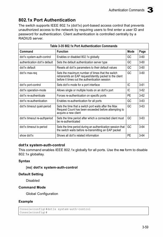
Authentication Commands
3-59
3802.1x Port Authentication The switch supports IEEE 802.1x (dot1x) port-based access control that prevents unauthorized access to the network by requiring users to first enter a user ID and password for authentication. Client authentication is controlled centrally by a RADIUS server.
dot1x system-auth-controlThis command enables IEEE 802.1x globally for all ports. Use the no form to disable 802.1x globallay.
Syntax
[no] dot1x system-auth-control
Default Setting
Disabled
Command Mode
Global Configuration
Example
Table 3-35 802.1x Port Authentication CommandsCommand Function Mode Pagedot1x system-auth-control Enables or disabled 802.1x globally GC 3-60authentication dot1x default Sets the default authentication server type GC 3-60dot1x default Resets all dot1x parameters to their default values GC 3-60dot1x max-req Sets the maximum number of times that the switch
retransmits an EAP request/identity packet to the client before it times out the authentication session
GC 3-60
dot1x port-control Sets dot1x mode for a port interface IC 3-61dot1x operation-mode Allows single or multiple hosts on an dot1x port IC 3-62dot1x re-authenticate Forces re-authentication on specific ports PE 3-62dot1x re-authentication Enables re-authentication for all ports GC 3-63dot1x timeout quiet-period Sets the time that a switch port waits after the Max
Request Count has been exceeded before attempting to acquire a new client
GC 3-63
dot1x timeout re-authperiod Sets the time period after which a connected client must be re-authenticated
GC 3-63
dot1x timeout tx-period Sets the time period during an authentication session that the switch waits before re-transmitting an EAP packet
GC 3-64
show dot1x Shows all dot1x related information PE 3-64
Console(config)#dot1x system-auth-controlConsole(config)#
Command Line Interface
3-60
3authentication dot1x defaultThis command sets the default authentication server type. Use the no form to restore the default.
Syntax
authentication dot1x default radiusno authentication dot1x
Default Setting
RADIUS
Command Mode
Global Configuration
Example
dot1x defaultThis command sets all configurable dot1x global and port settings to their default values.
Syntax
dot1x default
Command Mode
Global Configuration
Example
dot1x max-reqThis command sets the maximum number of times the switch port will retransmit an EAP request/identity packet to the client before it times out the authentication session. Use the no form to restore the default.
Syntax
dot1x max-req countno dot1x max-req
count – The maximum number of requests (Range: 1-10)
Default
2
Console(config)#authentication dot1x default radiusConsole(config)#
Console(config)#dot1x defaultConsole(config)#
Authentication Commands
3-61
3Command Mode
Global Configuration
Example
dot1x port-controlThis command sets the dot1x mode on a port interface. Use the no form to restore the default.
Syntax
dot1x port-control {auto | force-authorized | force-unauthorized}no dot1x port-control
• auto – Requires a dot1x-aware connected client to be authorized by the RADIUS server. Clients that are not dot1x-aware will be denied access.
• force-authorized – Configures the port to grant access to all clients, either dot1x-aware or otherwise.
• force-unauthorized – Configures the port to deny access to all clients, either dot1x-aware or otherwise.
Default
force-authorized
Command Mode
Interface Configuration
Example
Console(config)#dot1x max-req 2Console(config)#
Console(config)#interface eth 1/2Console(config-if)#dot1x port-control autoConsole(config-if)#
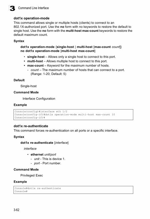
Command Line Interface
3-62
3dot1x operation-modeThis command allows single or multiple hosts (clients) to connect to an 802.1X-authorized port. Use the no form with no keywords to restore the default to single host. Use the no form with the multi-host max-count keywords to restore the default maximum count.
Syntax
dot1x operation-mode {single-host | multi-host [max-count count]}no dot1x operation-mode [multi-host max-count]
• single-host – Allows only a single host to connect to this port.• multi-host – Allows multiple host to connect to this port.• max-count – Keyword for the maximum number of hosts.
- count – The maximum number of hosts that can connect to a port. (Range: 1-20; Default: 5)
Default
Single-host
Command Mode
Interface Configuration
Example
dot1x re-authenticateThis command forces re-authentication on all ports or a specific interface.
Syntax
dot1x re-authenticate [interface]
interface
• ethernet unit/port- unit - This is device 1. - port - Port number.
Command Mode
Privileged Exec
Example
Console(config)#interface eth 1/2Console(config-if)#dot1x operation-mode multi-host max-count 10 Console(config-if)#
Console#dot1x re-authenticateConsole#
Authentication Commands
3-63
3dot1x re-authenticationThis command enables periodic re-authentication globally for all ports. Use the no form to disable re-authentication.
Syntax
[no] dot1x re-authentication
Command Mode
Global Configuration
Example
dot1x timeout quiet-periodThis command sets the time that a switch port waits after the Max Request Count has been exceeded before attempting to acquire a new client. Use the no form to reset the default.
Syntax
dot1x timeout quiet-period secondsno dot1x timeout quiet-period
seconds - The number of seconds. (Range: 1-65535)
Default
60 seconds
Command Mode
Global Configuration
Example
dot1x timeout re-authperiodThis command sets the time period after which a connected client must be re-authenticated.
Syntax
dot1x timeout re-authperiod secondsno dot1x timeout re-authperiod
seconds - The number of seconds. (Range: 1-65535)
Default
3600 seconds
Console(config)#dot1x re-authenticationConsole(config)#
Console(config)#dot1x timeout quiet-period 350Console(config)#
Command Line Interface
3-64
3Command Mode
Global Configuration
Example
dot1x timeout tx-periodThis command sets the time that the switch waits during an authentication session before re-transmitting an EAP packet. Use the no form to reset to the default value.
Syntax
dot1x timeout tx-period secondsno dot1x timeout tx-period
seconds - The number of seconds. (Range: 1-65535)
Default
30 seconds
Command Mode
Global Configuration
Example
show dot1xThis command shows general port authentication related settings on the switch or a specific interface.
Syntax
show dot1x [statistics] [interface interface]
interface
• ethernet unit/port
- unit - This is device 1. - port - Port number.
Command Mode
Privileged Exec
Command Usage
This command displays the following information:
Console(config)#dot1x timeout re-authperiod 300Console(config)#
Console(config)#dot1x timeout tx-period 300Console(config)#
Authentication Commands
3-65
3• Global 802.1X Parameters – Displays the global port access control
parameters that can be configured for this switch as described in the preceding pages, including reauth-enabled (page 3-63), reauth-period (page 3-63), quiet-period (page 3-63), tx-period (page 3-64), and max-req (page 3-60). It also displays the following global parameters which are set to a fixed value, including the following items:- supp-timeout – Supplicant timeout.- server-timeout – Server timeout.- reauth-max – Maximum number of reauthentication attempts.
• 802.1X Port Summary – Displays the port access control parameters for each interface, including the following items:- Status – Administrative state for port access control.- Mode – Dot1x port control mode (page 3-61).- Authorized – Authorization status (yes or n/a - not authorized).
• 802.1X Port Details – Displays detailed port access control settings for each interface as described in the preceding pages, including administrative status for port access control, Max request (page 3-60), Quiet period (page 3-63), Reauth period (page 3-63), Tx period (page 3-64), and Port-control (page 3-61). It also displays the following information:- Status – Authorization status (authorized or unauthorized).- Supplicant – MAC address of authorized client.
• Authenticator State Machine - State – Current state (including initialize, disconnected,
connecting, authenticating, authenticated, aborting, held, force_authorized, force_unauthorized).
- Reauth Count – Number of times connecting state is re-entered.• Backend State Machine
- State – Current state (including request, response, success, fail, timeout, idle, initialize).
- Request Count – Number of EAP Request packets sent to the Supplicant without receiving a response.
- Identifier(Server) – Identifier carried in the most recent EAP Success, Failure or Request packet received from the Authentication Server.
• Reauthentication State Machine - State – Current state (including initialize, reauthenticate).
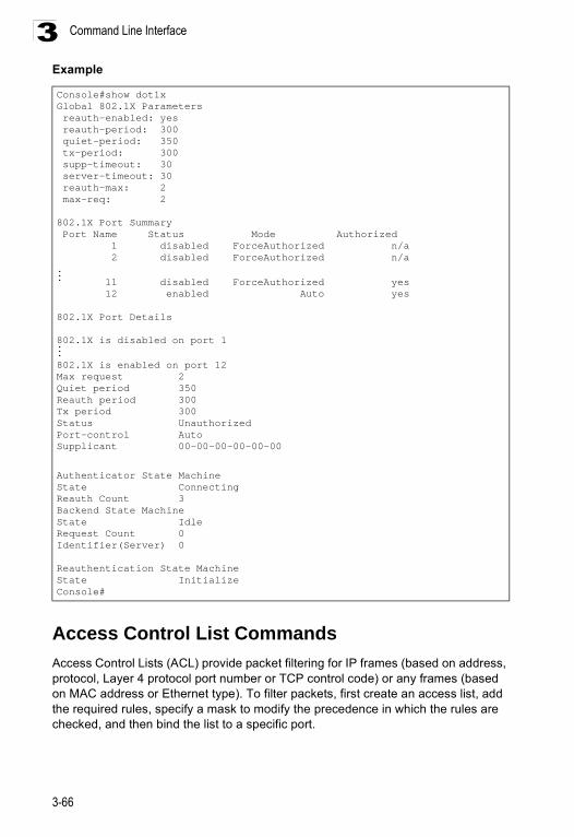
Command Line Interface
3-66
3Example
Access Control List CommandsAccess Control Lists (ACL) provide packet filtering for IP frames (based on address, protocol, Layer 4 protocol port number or TCP control code) or any frames (based on MAC address or Ethernet type). To filter packets, first create an access list, add the required rules, specify a mask to modify the precedence in which the rules are checked, and then bind the list to a specific port.
Console#show dot1xGlobal 802.1X Parameters reauth-enabled: yes reauth-period: 300 quiet-period: 350 tx-period: 300 supp-timeout: 30 server-timeout: 30 reauth-max: 2 max-req: 2
802.1X Port Summary Port Name Status Mode Authorized 1 disabled ForceAuthorized n/a 2 disabled ForceAuthorized n/a... 11 disabled ForceAuthorized yes 12 enabled Auto yes
802.1X Port Details
802.1X is disabled on port 1...802.1X is enabled on port 12Max request 2Quiet period 350Reauth period 300Tx period 300Status UnauthorizedPort-control AutoSupplicant 00-00-00-00-00-00
Authenticator State MachineState ConnectingReauth Count 3Backend State MachineState IdleRequest Count 0Identifier(Server) 0
Reauthentication State MachineState InitializeConsole#
Access Control List Commands
3-67
3Access Control ListsAn ACL is a sequential list of permit or deny conditions that apply to IP addresses, MAC addresses, or other more specific criteria. This switch tests ingress or egress packets against the conditions in an ACL one by one. A packet will be accepted as soon as it matches a permit rule, or dropped as soon as it matches a deny rule. If no rules match for a list of all permit rules, the packet is dropped; and if no rules match for a list of all deny rules, the packet is accepted.
There are three filtering modes:
• Standard IP ACL mode (STD-ACL) filters packets based on the source IP address. • Extended IP ACL mode (EXT-ACL) filters packets based on source or destination
IP address, as well as protocol type and protocol port number. If the TCP protocol is specified, then you can also filter packets based on the TCP control code.
• MAC ACL mode (MAC-ACL) filters packets based on the source or destination MAC address and the Ethernet frame type (RFC 1060).
The following restrictions apply to ACLs:
• This switch supports ACLs for both ingress and egress filtering. However, you can only bind one IP ACL and one MAC ACL to any port for ingress filtering, and one IP ACL and one MAC ACL to any port for egress filtering. In other words, only four ACLs can be bound to an interface – Ingress IP ACL, Egress IP ACL, Ingress MAC ACL and Egress MAC ACL.
• When an ACL is bound to an interface as an egress filter, all entries in the ACL must be deny rules. Otherwise, the bind operation will fail.
• Each ACL can have up to 32 rules.• The maximum number of ACLs is also 32.• However, due to resource restrictions, the average number of rules bound the
ports should not exceed 20.• You must configure a mask for an ACL rule before you can bind it to a port or set
the queue or frame priorities associated with the rule.• The switch does not support the explicit “deny any any” rule for the egress IP ACL
or the egress MAC ACLs. If these rules are included in ACL, and you attempt to bind the ACL to an interface for egress checking, the bind operation will fail.
• Egress MAC ACLs only work for destination-mac-known packets, not for multicast, broadcast, or destination-mac-unknown packets.
The order in which active ACLs are checked is as follows:1. User-defined rules in the Egress MAC ACL for egress ports.2. User-defined rules in the Egress IP ACL for egress ports.3. User-defined rules in the Ingress MAC ACL for ingress ports.4. User-defined rules in the Ingress IP ACL for ingress ports.5. Explicit default rule (permit any any) in the ingress IP ACL for ingress ports.6. Explicit default rule (permit any any) in the ingress MAC ACL for ingress ports.7. If no explicit rule is matched, the implicit default is permit all.
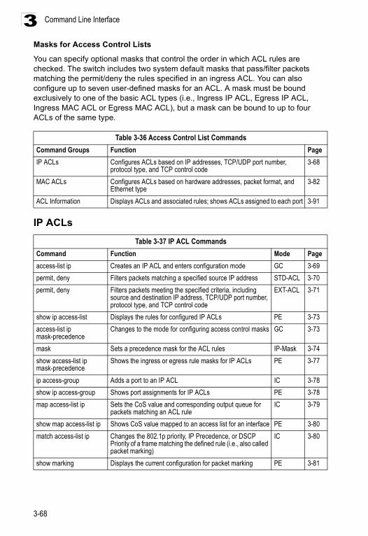
Command Line Interface
3-68
3Masks for Access Control Lists
You can specify optional masks that control the order in which ACL rules are checked. The switch includes two system default masks that pass/filter packets matching the permit/deny the rules specified in an ingress ACL. You can also configure up to seven user-defined masks for an ACL. A mask must be bound exclusively to one of the basic ACL types (i.e., Ingress IP ACL, Egress IP ACL, Ingress MAC ACL or Egress MAC ACL), but a mask can be bound to up to four ACLs of the same type.
IP ACLs
Table 3-36 Access Control List CommandsCommand Groups Function PageIP ACLs Configures ACLs based on IP addresses, TCP/UDP port number,
protocol type, and TCP control code3-68
MAC ACLs Configures ACLs based on hardware addresses, packet format, and Ethernet type
3-82
ACL Information Displays ACLs and associated rules; shows ACLs assigned to each port 3-91
Table 3-37 IP ACL CommandsCommand Function Mode Pageaccess-list ip Creates an IP ACL and enters configuration mode GC 3-69permit, deny Filters packets matching a specified source IP address STD-ACL 3-70permit, deny Filters packets meeting the specified criteria, including
source and destination IP address, TCP/UDP port number, protocol type, and TCP control code
EXT-ACL 3-71
show ip access-list Displays the rules for configured IP ACLs PE 3-73access-list ip mask-precedence
Changes to the mode for configuring access control masks GC 3-73
mask Sets a precedence mask for the ACL rules IP-Mask 3-74show access-list ip mask-precedence
Shows the ingress or egress rule masks for IP ACLs PE 3-77
ip access-group Adds a port to an IP ACL IC 3-78show ip access-group Shows port assignments for IP ACLs PE 3-78map access-list ip Sets the CoS value and corresponding output queue for
packets matching an ACL ruleIC 3-79
show map access-list ip Shows CoS value mapped to an access list for an interface PE 3-80match access-list ip Changes the 802.1p priority, IP Precedence, or DSCP
Priority of a frame matching the defined rule (i.e., also called packet marking)
IC 3-80
show marking Displays the current configuration for packet marking PE 3-81
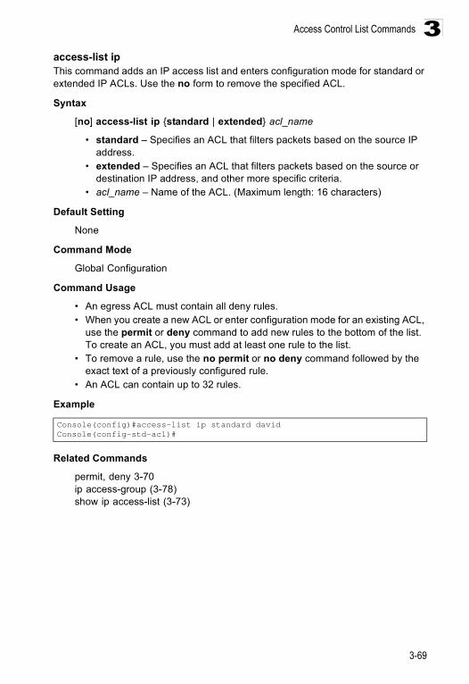
Access Control List Commands
3-69
3access-list ip This command adds an IP access list and enters configuration mode for standard or extended IP ACLs. Use the no form to remove the specified ACL.
Syntax
[no] access-list ip {standard | extended} acl_name
• standard – Specifies an ACL that filters packets based on the source IP address.
• extended – Specifies an ACL that filters packets based on the source or destination IP address, and other more specific criteria.
• acl_name – Name of the ACL. (Maximum length: 16 characters)
Default Setting
None
Command Mode
Global Configuration
Command Usage
• An egress ACL must contain all deny rules.• When you create a new ACL or enter configuration mode for an existing ACL,
use the permit or deny command to add new rules to the bottom of the list. To create an ACL, you must add at least one rule to the list.
• To remove a rule, use the no permit or no deny command followed by the exact text of a previously configured rule.
• An ACL can contain up to 32 rules.
Example
Related Commands
permit, deny 3-70ip access-group (3-78)show ip access-list (3-73)
Console(config)#access-list ip standard davidConsole(config-std-acl)#
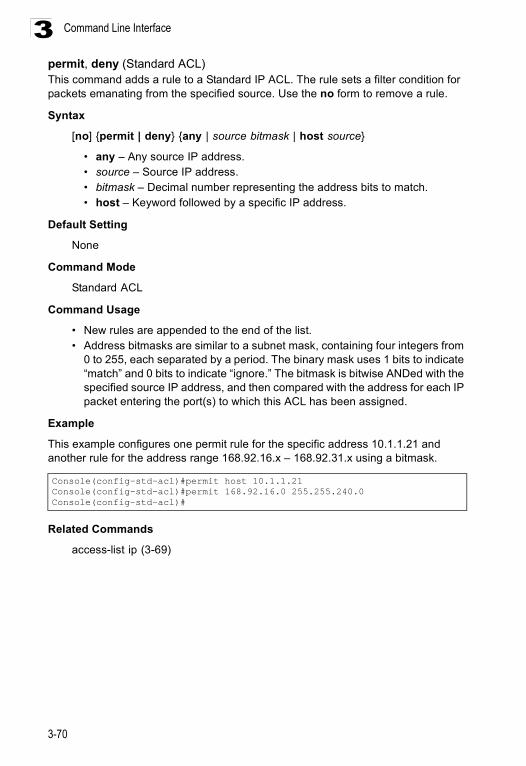
Command Line Interface
3-70
3permit, deny (Standard ACL) This command adds a rule to a Standard IP ACL. The rule sets a filter condition for packets emanating from the specified source. Use the no form to remove a rule.
Syntax
[no] {permit | deny} {any | source bitmask | host source}
• any – Any source IP address.• source – Source IP address.• bitmask – Decimal number representing the address bits to match.• host – Keyword followed by a specific IP address.
Default Setting
None
Command Mode
Standard ACL
Command Usage
• New rules are appended to the end of the list.• Address bitmasks are similar to a subnet mask, containing four integers from
0 to 255, each separated by a period. The binary mask uses 1 bits to indicate “match” and 0 bits to indicate “ignore.” The bitmask is bitwise ANDed with the specified source IP address, and then compared with the address for each IP packet entering the port(s) to which this ACL has been assigned.
Example
This example configures one permit rule for the specific address 10.1.1.21 and another rule for the address range 168.92.16.x – 168.92.31.x using a bitmask.
Related Commands
access-list ip (3-69)
Console(config-std-acl)#permit host 10.1.1.21Console(config-std-acl)#permit 168.92.16.0 255.255.240.0Console(config-std-acl)#
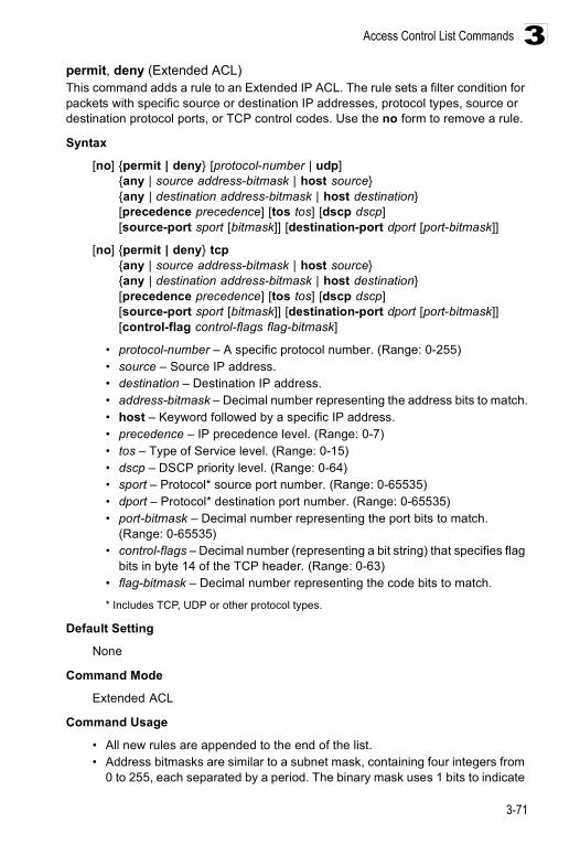
Access Control List Commands
3-71
3permit, deny (Extended ACL) This command adds a rule to an Extended IP ACL. The rule sets a filter condition for packets with specific source or destination IP addresses, protocol types, source or destination protocol ports, or TCP control codes. Use the no form to remove a rule.
Syntax
[no] {permit | deny} [protocol-number | udp] {any | source address-bitmask | host source} {any | destination address-bitmask | host destination}[precedence precedence] [tos tos] [dscp dscp][source-port sport [bitmask]] [destination-port dport [port-bitmask]]
[no] {permit | deny} tcp {any | source address-bitmask | host source} {any | destination address-bitmask | host destination}[precedence precedence] [tos tos] [dscp dscp][source-port sport [bitmask]] [destination-port dport [port-bitmask]][control-flag control-flags flag-bitmask]
• protocol-number – A specific protocol number. (Range: 0-255)• source – Source IP address.• destination – Destination IP address.• address-bitmask – Decimal number representing the address bits to match.• host – Keyword followed by a specific IP address.• precedence – IP precedence level. (Range: 0-7)• tos – Type of Service level. (Range: 0-15)• dscp – DSCP priority level. (Range: 0-64)• sport – Protocol* source port number. (Range: 0-65535)• dport – Protocol* destination port number. (Range: 0-65535)• port-bitmask – Decimal number representing the port bits to match.
(Range: 0-65535)• control-flags – Decimal number (representing a bit string) that specifies flag
bits in byte 14 of the TCP header. (Range: 0-63)• flag-bitmask – Decimal number representing the code bits to match.
* Includes TCP, UDP or other protocol types.
Default Setting
None
Command Mode
Extended ACL
Command Usage
• All new rules are appended to the end of the list.• Address bitmasks are similar to a subnet mask, containing four integers from
0 to 255, each separated by a period. The binary mask uses 1 bits to indicate
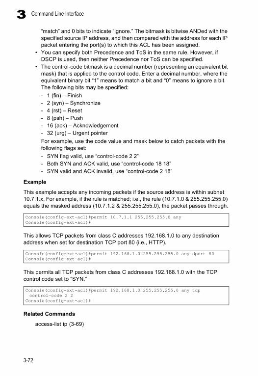
Command Line Interface
3-72
3“match” and 0 bits to indicate “ignore.” The bitmask is bitwise ANDed with the specified source IP address, and then compared with the address for each IP packet entering the port(s) to which this ACL has been assigned.
• You can specify both Precedence and ToS in the same rule. However, if DSCP is used, then neither Precedence nor ToS can be specified.
• The control-code bitmask is a decimal number (representing an equivalent bit mask) that is applied to the control code. Enter a decimal number, where the equivalent binary bit “1” means to match a bit and “0” means to ignore a bit. The following bits may be specified:- 1 (fin) – Finish- 2 (syn) – Synchronize- 4 (rst) – Reset- 8 (psh) – Push- 16 (ack) – Acknowledgement- 32 (urg) – Urgent pointerFor example, use the code value and mask below to catch packets with the following flags set: - SYN flag valid, use “control-code 2 2”- Both SYN and ACK valid, use “control-code 18 18”- SYN valid and ACK invalid, use “control-code 2 18”
Example
This example accepts any incoming packets if the source address is within subnet 10.7.1.x. For example, if the rule is matched; i.e., the rule (10.7.1.0 & 255.255.255.0) equals the masked address (10.7.1.2 & 255.255.255.0), the packet passes through.
This allows TCP packets from class C addresses 192.168.1.0 to any destination address when set for destination TCP port 80 (i.e., HTTP).
This permits all TCP packets from class C addresses 192.168.1.0 with the TCP control code set to “SYN.”
Related Commands
access-list ip (3-69)
Console(config-ext-acl)#permit 10.7.1.1 255.255.255.0 anyConsole(config-ext-acl)#
Console(config-ext-acl)#permit 192.168.1.0 255.255.255.0 any dport 80Console(config-ext-acl)#
Console(config-ext-acl)#permit 192.168.1.0 255.255.255.0 any tcp control-code 2 2
Console(config-ext-acl)#
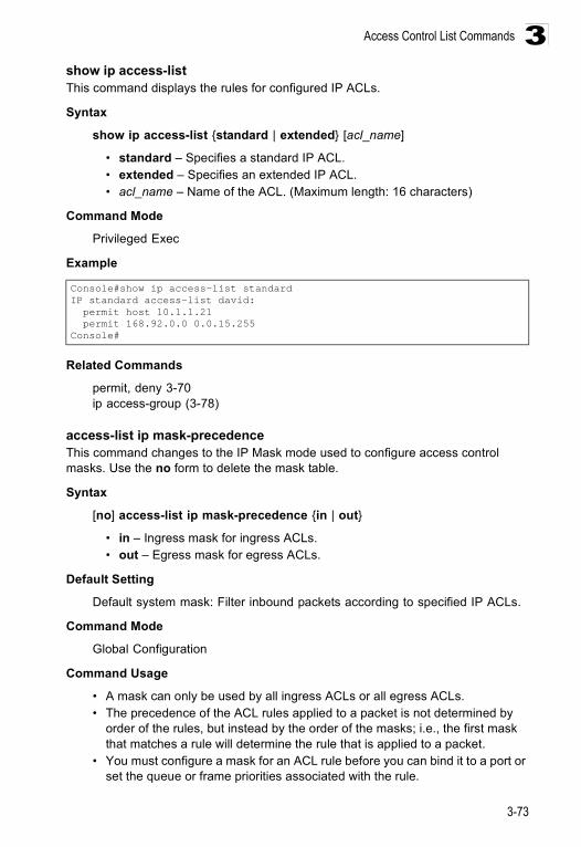
Access Control List Commands
3-73
3show ip access-list This command displays the rules for configured IP ACLs.
Syntax
show ip access-list {standard | extended} [acl_name]
• standard – Specifies a standard IP ACL.• extended – Specifies an extended IP ACL.• acl_name – Name of the ACL. (Maximum length: 16 characters)
Command Mode
Privileged Exec
Example
Related Commands
permit, deny 3-70ip access-group (3-78)
access-list ip mask-precedence This command changes to the IP Mask mode used to configure access control masks. Use the no form to delete the mask table.
Syntax
[no] access-list ip mask-precedence {in | out}
• in – Ingress mask for ingress ACLs.• out – Egress mask for egress ACLs.
Default Setting
Default system mask: Filter inbound packets according to specified IP ACLs.
Command Mode
Global Configuration
Command Usage
• A mask can only be used by all ingress ACLs or all egress ACLs.• The precedence of the ACL rules applied to a packet is not determined by
order of the rules, but instead by the order of the masks; i.e., the first mask that matches a rule will determine the rule that is applied to a packet.
• You must configure a mask for an ACL rule before you can bind it to a port or set the queue or frame priorities associated with the rule.
Console#show ip access-list standardIP standard access-list david: permit host 10.1.1.21 permit 168.92.0.0 0.0.15.255Console#
Command Line Interface
3-74
3Example
Related Commands
mask (IP ACL) (3-74)ip access-group (3-78)
mask (IP ACL)This command defines a mask for IP ACLs. This mask defines the fields to check in the IP header. Use the no form to remove a mask.
Syntax
[no] mask [protocol] {any | host | source-bitmask} {any | host | destination-bitmask} [precedence] [tos] [dscp] [source-port [port-bitmask]] [destination-port [port-bitmask]] [control-flag [flag-bitmask]]
• protocol – Check the protocol field.• any – Any address will be matched. • host – The address must be for a host device, not a subnetwork.• source-bitmask – Source address of rule must match this bitmask.• destination-bitmask – Destination address of rule must match this bitmask.• precedence – Check the IP precedence field.• tos – Check the TOS field.• dscp – Check the DSCP field.• source-port – Check the protocol source port field.• destination-port – Check the protocol destination port field.• port-bitmask – Protocol port of rule must match this bitmask.
(Range: 0-65535)• control-flag – Check the field for control flags.• flag-bitmask – Control flags of rule must match this bitmask. (Range: 0-63)
Default Setting
None
Command Mode
IP Mask
Command Usage
• Packets crossing a port are checked against all the rules in the ACL until a match is found. The order in which these packets are checked is determined by the mask, and not the order in which the ACL rules were entered.
Console(config)#access-list ip mask-precedence inConsole(config-ip-mask-acl)#
Access Control List Commands
3-75
3• First create the required ACLs and ingress or egress masks before mapping
an ACL to an interface.• If you enter dscp, you cannot enter tos or precedence. You can enter both
tos and precedence without dscp.• Masks that include an entry for a Layer 4 protocol source port or destination
port can only be applied to packets with a header length of exactly five bytes.
Example
This example creates an IP ingress mask with two rules. Each rule is checked in order of precedence to look for a match in the ACL entries. The first entry matching a mask is applied to the inbound packet.
This shows that the entries in the mask override the precedence in which the rules are entered into the ACL. In the following example, packets with the source address 10.1.1.1 are dropped because the “deny 10.1.1.1 255.255.255.255” rule has the higher precedence according the “mask host any” entry.
This shows how to create a standard ACL with an ingress mask to deny access to the IP host 171.69.198.102, and permit access to any others.
Console(config)#access-list ip mask-precedence inConsole(config-ip-mask-acl)#mask host anyConsole(config-ip-mask-acl)#mask 255.255.255.0 anyConsole(config-ip-mask-acl)#
Console(config)#access-list ip standard A2Console(config-std-acl)#permit 10.1.1.0 255.255.255.0Console(config-std-acl)#deny 10.1.1.1 255.255.255.255Console(config-std-acl)#exitConsole(config)#access-list ip mask-precedence inConsole(config-ip-mask-acl)#mask host anyConsole(config-ip-mask-acl)#mask 255.255.255.0 anyConsole(config-ip-mask-acl)#
Console(config)#access-list ip standard A2Console(config-std-acl)#permit anyConsole(config-std-acl)#deny host 171.69.198.102Console(config-std-acl)#endConsole#show access-listIP standard access-list A2: deny host 171.69.198.102 permit anyConsole#configureConsole(config)#access-list ip mask-precedence inConsole(config-ip-mask-acl)#mask host anyConsole(config-ip-mask-acl)#exitConsole(config)#interface ethernet 1/1Console(config-if)#ip access-group A2 inConsole(config-if)#endConsole#show access-listIP standard access-list A2: deny host 171.69.198.102 permit anyConsole#
Command Line Interface
3-76
3This shows how to create an extended ACL with an egress mask to drop packets leaving network 171.69.198.0 when the Layer 4 source port is 23.
Console(config)#access-list ip extended A3Console(config-ext-acl)#deny host 171.69.198.5 anyConsole(config-ext-acl)#deny 171.69.198.0 255.255.255.0 any source-port 23Console(config-ext-acl)#endConsole#show access-listIP extended access-list A3: deny host 171.69.198.5 any deny 171.69.198.0 255.255.255.0 any source-port 23Console#configConsole(config)#access-list ip mask-precedence outConsole(config-ip-mask-acl)#mask 255.255.255.0 any source-portConsole(config-ip-mask-acl)#exitConsole(config)#interface ethernet 1/15Console(config-if)#ip access-group A3 outConsole(config-if)#endConsole#show access-listIP extended access-list A3: deny 171.69.198.0 255.255.255.0 any source-port 23 deny host 171.69.198.5 anyIP egress mask ACL: mask 255.255.255.0 any source-portConsole#
Access Control List Commands
3-77
3This is a more comprehensive example. It denies any TCP packets in which the SYN bit is ON, and permits all other packets. It then sets the ingress mask to check the deny rule first, and finally binds port 1 to this ACL. Note that once the ACL is bound to an interface (i.e., the ACL is active), the order in which the rules are displayed is determined by the associated mask.
show access-list ip mask-precedence This command shows the ingress or egress rule masks for IP ACLs.
Syntax
show access-list ip mask-precedence [in | out]
• in – Ingress mask precedence for ingress ACLs.• out – Egress mask precedence for egress ACLs.
Command Mode
Privileged Exec
Example
Switch(config)#access-list ip extended 6Switch(config-ext-acl)#permit any anySwitch(config-ext-acl)#deny tcp any any control-flag 2 2Switch(config-ext-acl)#end Console#show access-listIP extended access-list A6: permit any any deny tcp any any control-flag 2 2Console#configureSwitch(config)#access-list ip mask-precedence inSwitch(config-ip-mask-acl)#mask protocol any any control-flag 2Switch(config-ip-mask-acl)#endConsole#sh access-listIP extended access-list A6: permit any any deny tcp any any control-flag 2 2IP ingress mask ACL: mask protocol any any control-flag 2Console#configureConsole(config)#interface ethernet 1/1Console(config-if)#ip access-group A6 inConsole(config-if)#endConsole#show access-listIP extended access-list A6: deny tcp any any control-flag 2 2 permit any anyIP ingress mask ACL: mask protocol any any control-flag 2Console#
Console#show access-list ip mask-precedenceIP ingress mask ACL: mask host any mask 255.255.255.0 anyConsole#
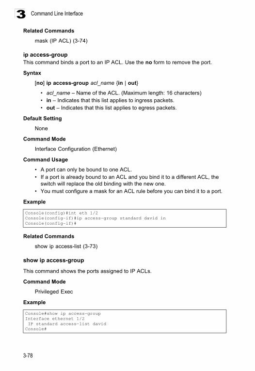
Command Line Interface
3-78
3Related Commands
mask (IP ACL) (3-74)
ip access-group This command binds a port to an IP ACL. Use the no form to remove the port.
Syntax
[no] ip access-group acl_name {in | out}
• acl_name – Name of the ACL. (Maximum length: 16 characters)• in – Indicates that this list applies to ingress packets.• out – Indicates that this list applies to egress packets.
Default Setting
None
Command Mode
Interface Configuration (Ethernet)
Command Usage
• A port can only be bound to one ACL.• If a port is already bound to an ACL and you bind it to a different ACL, the
switch will replace the old binding with the new one. • You must configure a mask for an ACL rule before you can bind it to a port.
Example
Related Commands
show ip access-list (3-73)
show ip access-group
This command shows the ports assigned to IP ACLs.
Command Mode
Privileged Exec
Example
Console(config)#int eth 1/2Console(config-if)#ip access-group standard david inConsole(config-if)#
Console#show ip access-groupInterface ethernet 1/2 IP standard access-list davidConsole#
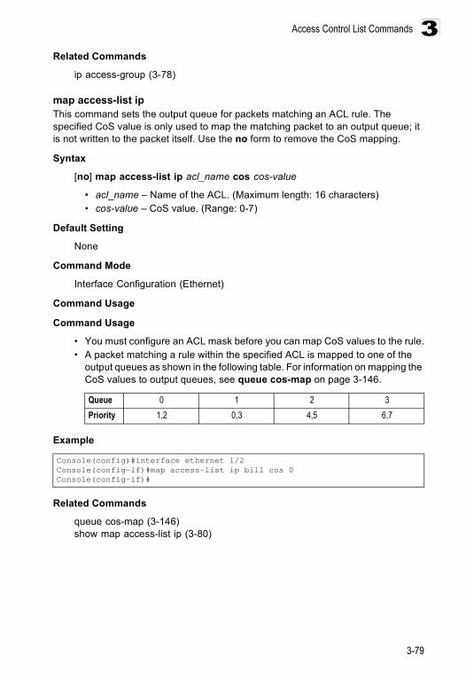
Access Control List Commands
3-79
3Related Commands
ip access-group (3-78)
map access-list ip This command sets the output queue for packets matching an ACL rule. The specified CoS value is only used to map the matching packet to an output queue; it is not written to the packet itself. Use the no form to remove the CoS mapping.
Syntax
[no] map access-list ip acl_name cos cos-value
• acl_name – Name of the ACL. (Maximum length: 16 characters)• cos-value – CoS value. (Range: 0-7)
Default Setting
None
Command Mode
Interface Configuration (Ethernet)
Command Usage
Command Usage
• You must configure an ACL mask before you can map CoS values to the rule.• A packet matching a rule within the specified ACL is mapped to one of the
output queues as shown in the following table. For information on mapping the CoS values to output queues, see queue cos-map on page 3-146.
Example
Related Commands
queue cos-map (3-146)show map access-list ip (3-80)
Queue 0 1 2 3Priority 1,2 0,3 4,5 6,7
Console(config)#interface ethernet 1/2Console(config-if)#map access-list ip bill cos 0Console(config-if)#
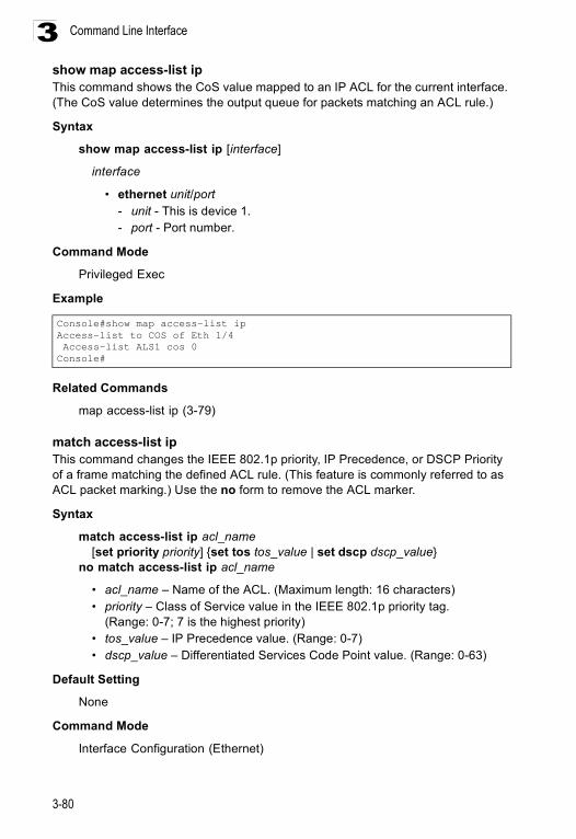
Command Line Interface
3-80
3show map access-list ip This command shows the CoS value mapped to an IP ACL for the current interface. (The CoS value determines the output queue for packets matching an ACL rule.)
Syntax
show map access-list ip [interface]
interface
• ethernet unit/port- unit - This is device 1. - port - Port number.
Command Mode
Privileged Exec
Example
Related Commands
map access-list ip (3-79)
match access-list ip This command changes the IEEE 802.1p priority, IP Precedence, or DSCP Priority of a frame matching the defined ACL rule. (This feature is commonly referred to as ACL packet marking.) Use the no form to remove the ACL marker.
Syntax
match access-list ip acl_name [set priority priority] {set tos tos_value | set dscp dscp_value}
no match access-list ip acl_name
• acl_name – Name of the ACL. (Maximum length: 16 characters)• priority – Class of Service value in the IEEE 802.1p priority tag.
(Range: 0-7; 7 is the highest priority)• tos_value – IP Precedence value. (Range: 0-7)• dscp_value – Differentiated Services Code Point value. (Range: 0-63)
Default Setting
None
Command Mode
Interface Configuration (Ethernet)
Console#show map access-list ipAccess-list to COS of Eth 1/4 Access-list ALS1 cos 0Console#
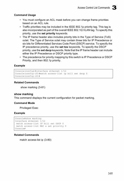
Access Control List Commands
3-81
3Command Usage
• You must configure an ACL mask before you can change frame priorities based on an ACL rule.
• Traffic priorities may be included in the IEEE 802.1p priority tag. This tag is also incorporated as part of the overall IEEE 802.1Q VLAN tag. To specify this priority, use the set priority keywords.
• The IP frame header also includes priority bits in the Type of Service (ToS) octet. The Type of Service octet may contain three bits for IP Precedence or six bits for Differentiated Services Code Point (DSCP) service. To specify the IP precedence priority, use the set tos keywords. To specify the DSCP priority, use the set dscp keywords. Note that the IP frame header can include either the IP Precedence or DSCP priority type.
• The precedence for priority mapping by this switch is IP Precedence or DSCP Priority, and then 802.1p priority.
Example
Related Commands
show marking (3-81)
show marking This command displays the current configuration for packet marking.
Command Mode
Privileged Exec
Example
Related Commands
match access-list ip (3-80)
Console(config)#interface ethernet 1/12Console(config-if)#match access-list ip bill set dscp 0Console(config-if)#
Console#show markingInterface ethernet 1/12 match access-list IP bill set DSCP 0 match access-list MAC a set priority 0Console#
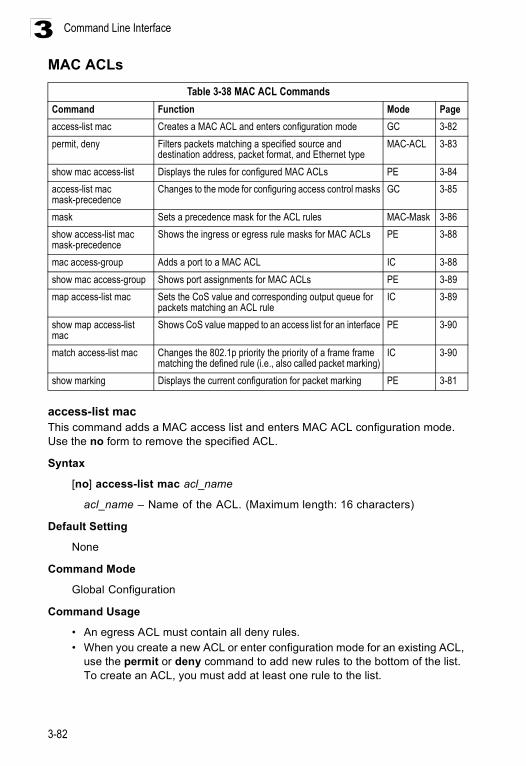
Command Line Interface
3-82
3MAC ACLs
access-list mac This command adds a MAC access list and enters MAC ACL configuration mode. Use the no form to remove the specified ACL.
Syntax
[no] access-list mac acl_name
acl_name – Name of the ACL. (Maximum length: 16 characters)
Default Setting
None
Command Mode
Global Configuration
Command Usage
• An egress ACL must contain all deny rules.• When you create a new ACL or enter configuration mode for an existing ACL,
use the permit or deny command to add new rules to the bottom of the list. To create an ACL, you must add at least one rule to the list.
Table 3-38 MAC ACL CommandsCommand Function Mode Pageaccess-list mac Creates a MAC ACL and enters configuration mode GC 3-82permit, deny Filters packets matching a specified source and
destination address, packet format, and Ethernet typeMAC-ACL 3-83
show mac access-list Displays the rules for configured MAC ACLs PE 3-84access-list mac mask-precedence
Changes to the mode for configuring access control masks GC 3-85
mask Sets a precedence mask for the ACL rules MAC-Mask 3-86show access-list mac mask-precedence
Shows the ingress or egress rule masks for MAC ACLs PE 3-88
mac access-group Adds a port to a MAC ACL IC 3-88show mac access-group Shows port assignments for MAC ACLs PE 3-89map access-list mac Sets the CoS value and corresponding output queue for
packets matching an ACL ruleIC 3-89
show map access-list mac
Shows CoS value mapped to an access list for an interface PE 3-90
match access-list mac Changes the 802.1p priority the priority of a frame frame matching the defined rule (i.e., also called packet marking)
IC 3-90
show marking Displays the current configuration for packet marking PE 3-81
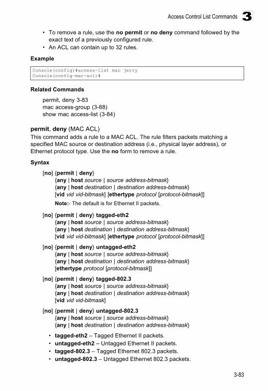
Access Control List Commands
3-83
3• To remove a rule, use the no permit or no deny command followed by the
exact text of a previously configured rule.• An ACL can contain up to 32 rules.
Example
Related Commands
permit, deny 3-83mac access-group (3-88)show mac access-list (3-84)
permit, deny (MAC ACL)This command adds a rule to a MAC ACL. The rule filters packets matching a specified MAC source or destination address (i.e., physical layer address), or Ethernet protocol type. Use the no form to remove a rule.
Syntax
[no] {permit | deny}{any | host source | source address-bitmask} {any | host destination | destination address-bitmask}[vid vid vid-bitmask] [ethertype protocol [protocol-bitmask]]Note:- The default is for Ethernet II packets.
[no] {permit | deny} tagged-eth2 {any | host source | source address-bitmask} {any | host destination | destination address-bitmask}[vid vid vid-bitmask] [ethertype protocol [protocol-bitmask]]
[no] {permit | deny} untagged-eth2{any | host source | source address-bitmask} {any | host destination | destination address-bitmask}[ethertype protocol [protocol-bitmask]]
[no] {permit | deny} tagged-802.3 {any | host source | source address-bitmask} {any | host destination | destination address-bitmask}[vid vid vid-bitmask]
[no] {permit | deny} untagged-802.3 {any | host source | source address-bitmask} {any | host destination | destination address-bitmask}
• tagged-eth2 – Tagged Ethernet II packets.• untagged-eth2 – Untagged Ethernet II packets.• tagged-802.3 – Tagged Ethernet 802.3 packets.• untagged-802.3 – Untagged Ethernet 802.3 packets.
Console(config)#access-list mac jerryConsole(config-mac-acl)#
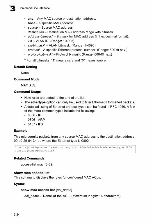
Command Line Interface
3-84
3• any – Any MAC source or destination address. • host – A specific MAC address.• source – Source MAC address.• destination – Destination MAC address range with bitmask.• address-bitmask* – Bitmask for MAC address (in hexidecimal format).• vid – VLAN ID. (Range: 1-4095)• vid-bitmask* – VLAN bitmask. (Range: 1-4095)• protocol – A specific Ethernet protocol number. (Range: 600-fff hex.)• protocol-bitmask* – Protocol bitmask. (Range: 600-fff hex.)
* For all bitmasks, “1” means care and “0” means ignore.
Default Setting
None
Command Mode
MAC ACL
Command Usage
• New rules are added to the end of the list.• The ethertype option can only be used to filter Ethernet II formatted packets. • A detailed listing of Ethernet protocol types can be found in RFC 1060. A few
of the more common types include the following:- 0800 - IP- 0806 - ARP- 8137 - IPX
Example
This rule permits packets from any source MAC address to the destination address 00-e0-29-94-34-de where the Ethernet type is 0800.
Related Commands
access-list mac (3-82)
show mac access-list This command displays the rules for configured MAC ACLs.
Syntax
show mac access-list [acl_name]
acl_name – Name of the ACL. (Maximum length: 16 characters)
Console(config-mac-acl)#permit any host 00-e0-29-94-34-de ethertype 0800Console(config-mac-acl)#
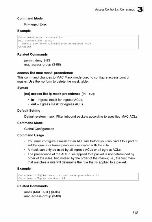
Access Control List Commands
3-85
3Command Mode
Privileged Exec
Example
Related Commands
permit, deny 3-83mac access-group (3-88)
access-list mac mask-precedence This command changes to MAC Mask mode used to configure access control masks. Use the no form to delete the mask table.
Syntax
[no] access-list ip mask-precedence {in | out}
• in – Ingress mask for ingress ACLs.• out – Egress mask for egress ACLs.
Default Setting
Default system mask: Filter inbound packets according to specified MAC ACLs.
Command Mode
Global Configuration
Command Usage
• You must configure a mask for an ACL rule before you can bind it to a port or set the queue or frame priorities associated with the rule.
• A mask can only be used by all ingress ACLs or all egress ACLs.• The precedence of the ACL rules applied to a packet is not determined by
order of the rules, but instead by the order of the masks; i.e., the first mask that matches a rule will determine the rule that is applied to a packet.
Example
Related Commands
mask (MAC ACL) (3-86)mac access-group (3-88)
Console#show mac access-listMAC access-list jerry: permit any 00-e0-29-94-34-de ethertype 0800Console#
Console(config)#access-list mac mask-precedence inConsole(config-mac-mask-acl)#
Command Line Interface
3-86
3mask (MAC ACL)This command defines a mask for MAC ACLs. This mask defines the fields to check in the packet header. Use the no form to remove a mask.
Syntax
[no] mask [pktformat] {any | host | source-bitmask} {any | host | destination-bitmask} [vid [vid-bitmask]] [ethertype [ethertype-bitmask]]
• pktformat – Check the packet format field. (If this keyword must be used in the mask, the packet format must be specified in ACL rule to match.)
• any – Any address will be matched. • host – The address must be for a single node.• source-bitmask – Source address of rule must match this bitmask.• destination-bitmask – Destination address of rule must match this bitmask.• vid – Check the VLAN ID field.• vid-bitmask – VLAN ID of rule must match this bitmask.• ethertype – Check the Ethernet type field.• ethertype-bitmask – Ethernet type of rule must match this bitmask.
Default Setting
None
Command Mode
MAC Mask
Command Usage
• Up to seven masks can be assigned to an ingress or egress ACL.• Packets crossing a port are checked against all the rules in the ACL until a
match is found. The order in which these packets are checked is determined by the mask, and not the order in which the ACL rules were entered.
• First create the required ACLs and inbound or outbound masks before mapping an ACL to an interface.
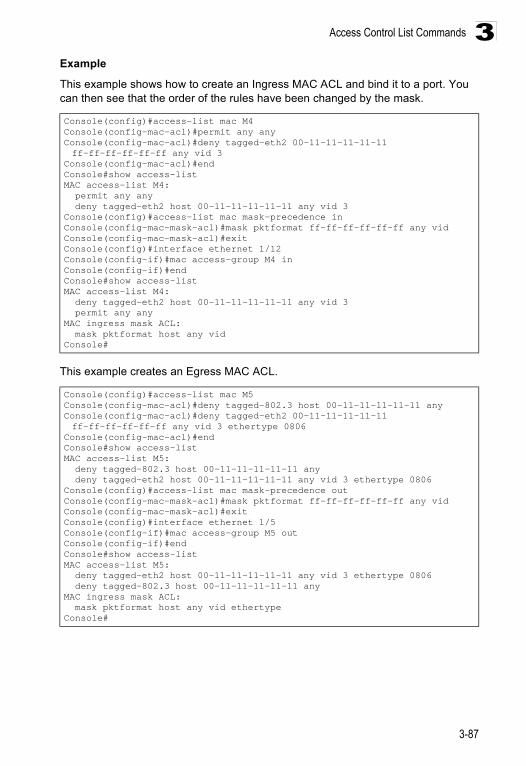
Access Control List Commands
3-87
3Example
This example shows how to create an Ingress MAC ACL and bind it to a port. You can then see that the order of the rules have been changed by the mask.
This example creates an Egress MAC ACL.
Console(config)#access-list mac M4Console(config-mac-acl)#permit any anyConsole(config-mac-acl)#deny tagged-eth2 00-11-11-11-11-11 ff-ff-ff-ff-ff-ff any vid 3
Console(config-mac-acl)#endConsole#show access-listMAC access-list M4: permit any any deny tagged-eth2 host 00-11-11-11-11-11 any vid 3Console(config)#access-list mac mask-precedence inConsole(config-mac-mask-acl)#mask pktformat ff-ff-ff-ff-ff-ff any vidConsole(config-mac-mask-acl)#exitConsole(config)#interface ethernet 1/12Console(config-if)#mac access-group M4 inConsole(config-if)#endConsole#show access-listMAC access-list M4: deny tagged-eth2 host 00-11-11-11-11-11 any vid 3 permit any anyMAC ingress mask ACL: mask pktformat host any vidConsole#
Console(config)#access-list mac M5Console(config-mac-acl)#deny tagged-802.3 host 00-11-11-11-11-11 anyConsole(config-mac-acl)#deny tagged-eth2 00-11-11-11-11-11 ff-ff-ff-ff-ff-ff any vid 3 ethertype 0806
Console(config-mac-acl)#endConsole#show access-listMAC access-list M5: deny tagged-802.3 host 00-11-11-11-11-11 any deny tagged-eth2 host 00-11-11-11-11-11 any vid 3 ethertype 0806Console(config)#access-list mac mask-precedence outConsole(config-mac-mask-acl)#mask pktformat ff-ff-ff-ff-ff-ff any vidConsole(config-mac-mask-acl)#exitConsole(config)#interface ethernet 1/5Console(config-if)#mac access-group M5 outConsole(config-if)#endConsole#show access-listMAC access-list M5: deny tagged-eth2 host 00-11-11-11-11-11 any vid 3 ethertype 0806 deny tagged-802.3 host 00-11-11-11-11-11 anyMAC ingress mask ACL: mask pktformat host any vid ethertypeConsole#
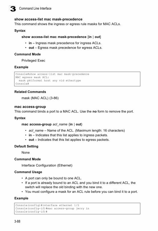
Command Line Interface
3-88
3show access-list mac mask-precedence This command shows the ingress or egress rule masks for MAC ACLs.
Syntax
show access-list mac mask-precedence [in | out]
• in – Ingress mask precedence for ingress ACLs.• out – Egress mask precedence for egress ACLs.
Command Mode
Privileged Exec
Example
Related Commands
mask (MAC ACL) (3-86)
mac access-groupThis command binds a port to a MAC ACL. Use the no form to remove the port.
Syntax
mac access-group acl_name {in | out}
• acl_name – Name of the ACL. (Maximum length: 16 characters)• in – Indicates that this list applies to ingress packets.• out – Indicates that this list applies to egress packets.
Default Setting
None
Command Mode
Interface Configuration (Ethernet)
Command Usage
• A port can only be bound to one ACL.• If a port is already bound to an ACL and you bind it to a different ACL, the
switch will replace the old binding with the new one. • You must configure a mask for an ACL rule before you can bind it to a port.
Example
Console#show access-list mac mask-precedenceMAC egress mask ACL: mask pktformat host any vid ethertypeConsole#
Console(config)#interface ethernet 1/2Console(config-if)#mac access-group jerry inConsole(config-if)#
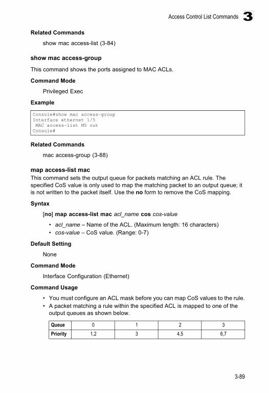
Access Control List Commands
3-89
3Related Commands
show mac access-list (3-84)
show mac access-group
This command shows the ports assigned to MAC ACLs.
Command Mode
Privileged Exec
Example
Related Commands
mac access-group (3-88)
map access-list mac This command sets the output queue for packets matching an ACL rule. The specified CoS value is only used to map the matching packet to an output queue; it is not written to the packet itself. Use the no form to remove the CoS mapping.
Syntax
[no] map access-list mac acl_name cos cos-value
• acl_name – Name of the ACL. (Maximum length: 16 characters)• cos-value – CoS value. (Range: 0-7)
Default Setting
None
Command Mode
Interface Configuration (Ethernet)
Command Usage
• You must configure an ACL mask before you can map CoS values to the rule.• A packet matching a rule within the specified ACL is mapped to one of the
output queues as shown below.
Console#show mac access-groupInterface ethernet 1/5 MAC access-list M5 outConsole#
Queue 0 1 2 3Priority 1,2 3 4,5 6,7
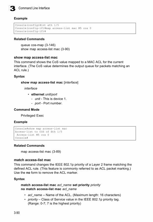
Command Line Interface
3-90
3Example
Related Commands
queue cos-map (3-146)show map access-list mac (3-90)
show map access-list mac This command shows the CoS value mapped to a MAC ACL for the current interface. (The CoS value determines the output queue for packets matching an ACL rule.)
Syntax
show map access-list mac [interface]
interface
• ethernet unit/port- unit - This is device 1. - port - Port number.
Command Mode
Privileged Exec
Example
Related Commands
map access-list mac (3-89)
match access-list mac This command changes the IEEE 802.1p priority of a Layer 2 frame matching the defined ACL rule. (This feature is commonly referred to as ACL packet marking.) Use the no form to remove the ACL marker.
Syntax
match access-list mac acl_name set priority priorityno match access-list mac acl_name
• acl_name – Name of the ACL. (Maximum length: 16 characters)• priority – Class of Service value in the IEEE 802.1p priority tag.
(Range: 0-7; 7 is the highest priority)
Console(config)#int eth 1/5Console(config-if)#map access-list mac M5 cos 0Console(config-if)#
Console#show map access-list macAccess-list to COS of Eth 1/5 Access-list M5 cos 0Console#
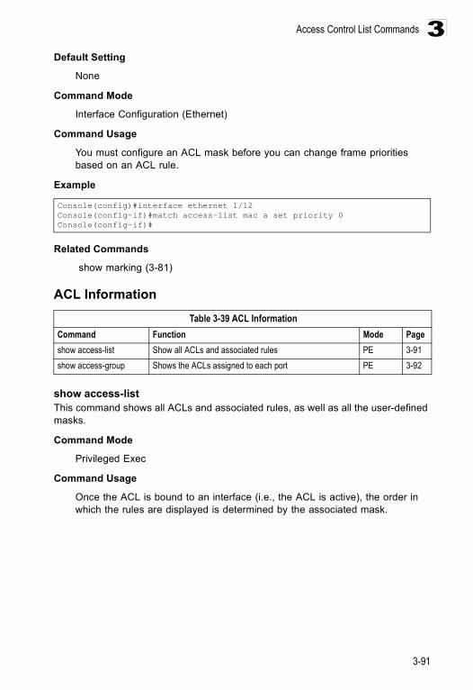
Access Control List Commands
3-91
3Default Setting
None
Command Mode
Interface Configuration (Ethernet)
Command Usage
You must configure an ACL mask before you can change frame priorities based on an ACL rule.
Example
Related Commands
show marking (3-81)
ACL Information
show access-listThis command shows all ACLs and associated rules, as well as all the user-defined masks.
Command Mode
Privileged Exec
Command Usage
Once the ACL is bound to an interface (i.e., the ACL is active), the order in which the rules are displayed is determined by the associated mask.
Console(config)#interface ethernet 1/12Console(config-if)#match access-list mac a set priority 0Console(config-if)#
Table 3-39 ACL InformationCommand Function Mode Pageshow access-list Show all ACLs and associated rules PE 3-91show access-group Shows the ACLs assigned to each port PE 3-92
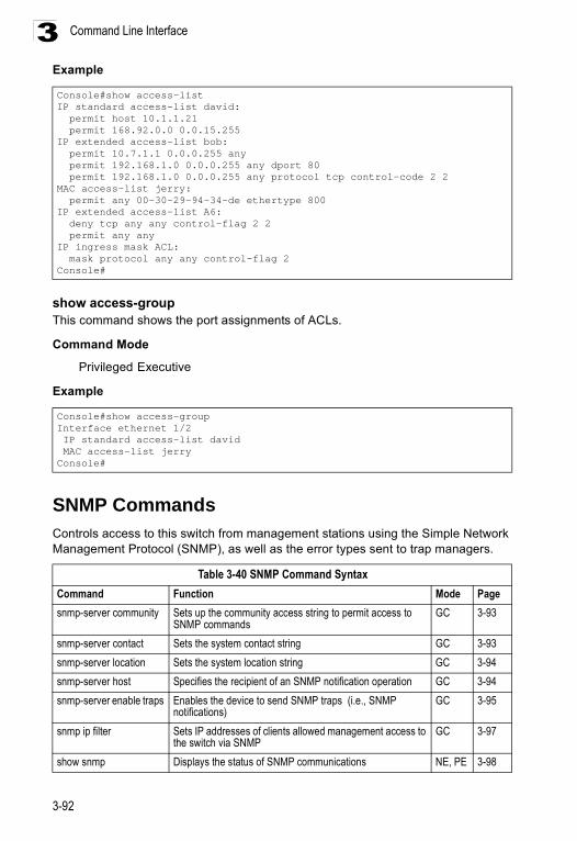
Command Line Interface
3-92
3Example
show access-groupThis command shows the port assignments of ACLs.
Command Mode
Privileged Executive
Example
SNMP CommandsControls access to this switch from management stations using the Simple Network Management Protocol (SNMP), as well as the error types sent to trap managers.
Console#show access-listIP standard access-list david: permit host 10.1.1.21 permit 168.92.0.0 0.0.15.255IP extended access-list bob: permit 10.7.1.1 0.0.0.255 any permit 192.168.1.0 0.0.0.255 any dport 80 permit 192.168.1.0 0.0.0.255 any protocol tcp control-code 2 2MAC access-list jerry: permit any 00-30-29-94-34-de ethertype 800IP extended access-list A6: deny tcp any any control-flag 2 2 permit any anyIP ingress mask ACL: mask protocol any any control-flag 2Console#
Console#show access-groupInterface ethernet 1/2 IP standard access-list david MAC access-list jerryConsole#
Table 3-40 SNMP Command SyntaxCommand Function Mode Pagesnmp-server community Sets up the community access string to permit access to
SNMP commands GC 3-93
snmp-server contact Sets the system contact string GC 3-93snmp-server location Sets the system location string GC 3-94snmp-server host Specifies the recipient of an SNMP notification operation GC 3-94snmp-server enable traps Enables the device to send SNMP traps (i.e., SNMP
notifications) GC 3-95
snmp ip filter Sets IP addresses of clients allowed management access to the switch via SNMP
GC 3-97
show snmp Displays the status of SNMP communications NE, PE 3-98
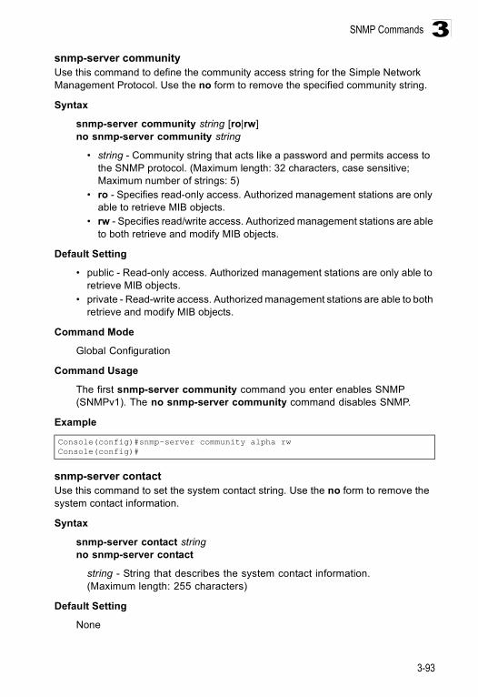
SNMP Commands
3-93
3snmp-server communityUse this command to define the community access string for the Simple Network Management Protocol. Use the no form to remove the specified community string.
Syntax
snmp-server community string [ro|rw]no snmp-server community string
• string - Community string that acts like a password and permits access to the SNMP protocol. (Maximum length: 32 characters, case sensitive; Maximum number of strings: 5)
• ro - Specifies read-only access. Authorized management stations are only able to retrieve MIB objects.
• rw - Specifies read/write access. Authorized management stations are able to both retrieve and modify MIB objects.
Default Setting
• public - Read-only access. Authorized management stations are only able to retrieve MIB objects.
• private - Read-write access. Authorized management stations are able to both retrieve and modify MIB objects.
Command Mode
Global Configuration
Command Usage
The first snmp-server community command you enter enables SNMP (SNMPv1). The no snmp-server community command disables SNMP.
Example
snmp-server contactUse this command to set the system contact string. Use the no form to remove the system contact information.
Syntax
snmp-server contact stringno snmp-server contact
string - String that describes the system contact information. (Maximum length: 255 characters)
Default Setting
None
Console(config)#snmp-server community alpha rwConsole(config)#
Command Line Interface
3-94
3Command Mode
Global Configuration
Example
Related Commands
snmp-server location (3-94)
snmp-server locationUse this command to set the system location string. Use the no form to remove the location string.
Syntax
snmp-server location textno snmp-server location
text - String that describes the system location. (Maximum length: 255 characters)
Default Setting
None
Command Mode
Global Configuration
Example
Related Commands
snmp-server contact (3-93)
snmp-server hostUse this command to specify the recipient of a Simple Network Management Protocol notification operation. Use the no form to remove the specified host.
Syntax
snmp-server host host-addr community-string [version {1 | 2c}]no snmp-server host host-addr
• host-addr - Internet address of the host (the targeted recipient). (Maximum host addresses: 5 trap destination IP address entries)
• community-string - Password-like community string sent with the notification operation. Although you can set this string using the snmp-server host command by itself, we recommend that you define this
Console(config)#snmp-server contact PaulConsole(config)#
Console(config)#snmp-server location WC-19Console(config)#
SNMP Commands
3-95
3string using the snmp-server community command prior to using the snmp-server host command. (Maximum length: 32 characters)
• version - Specifies whether to send notifications as SNMP v1 or v2c traps.
Default Setting
Host Address: NoneSNMP Version: 1
Command Mode
Global Configuration
Command Usage
• If you do not enter an snmp-server host command, no notifications are sent. In order to configure the switch to send SNMP notifications, you must enter at least one snmp-server host command. In order to enable multiple hosts, you must issue a separate snmp-server host command for each host.
• The snmp-server host command is used in conjunction with the snmp-server enable traps command. Use the snmp-server enable traps command to specify which SNMP notifications are sent globally. For a host to receive notifications, at least one snmp-server enable traps command and the snmp-server host command for that host must be enabled.
• Some notification types cannot be controlled with the snmp-server enable traps command. For example, some notification types are always enabled.
• The switch can send SNMP version 1 or version 2c notifications to a host IP address, depending on the SNMP version that the management station supports. If the snmp-server host command does not specify the SNMP version, the default is to send SNMP version 1 notifications.
Example
Related Commands
snmp-server enable traps (3-95)
snmp-server enable trapsUse this command to enable this device to send Simple Network Management Protocol traps (SNMP notifications). Use the no form to disable SNMP notifications.
Syntax
[no] snmp-server enable traps [authentication | link-up-down]
• authentication - Keyword to issue authentication failure traps. • link-up-down - Keyword to issue link-up or link-down traps.
The link-up-down trap can only be enabled/disabled via the CLI.
Console(config)#snmp-server host 10.1.19.23 batmanConsole(config)#
Command Line Interface
3-96
3Default Setting
Issue authentication and link-up-down traps.
Command Mode
Global Configuration
Command Usage
• If you do not enter an snmp-server enable traps command, no notifications controlled by this command are sent. In order to configure this device to send SNMP notifications, you must enter at least one snmp-server enable traps command. If you enter the command with no keywords, both authentication and link-up-down notifications are enabled. If you enter the command with a keyword, only the notification type related to that keyword is enabled.
• The snmp-server enable traps command is used in conjunction with the snmp-server host command. Use the snmp-server host command to specify which host or hosts receive SNMP notifications. In order to send notifications, you must configure at least one snmp-server host command.
Example
Related Commands
snmp-server host (3-94)
Console(config)#snmp-server enable traps link-up-downConsole(config)#
SNMP Commands
3-97
3snmp ip filterThis command sets the IP addresses of clients that are allowed management access to the switch via SNMP. Use the no form the remove an IP address.
Syntax[no] snmp ip filter ip_address subnet_mask
• ip_address - An IP address indicating a client or group of clients that are allowed SNMP access to the switch.
• subnet_mask - An address bitmask of decimal numbers that represent the address bits to match.
Default Setting None
Command Mode Global Configuration
Command Usage • You can create a list of up to 16 IP addresses or IP address groups that are
allowed access to the switch via SNMP management software.• Address bitmasks are similar to a subnet mask, containing four decimal
integers from 0 to 255, each separated by a period. The binary mask uses “1” bits to indicate “match” and “0” bits to indicate “ignore.”
• If the IP is the address of a single management station, the bitmask should be set to 255.255.255.255. Otherwise, an IP address group is specified by the bitmask.
• The default setting is null, which allows all IP groups SNMP access to the switch. If one IP address is configured, IP filtering is enabled and only addresses in the specified IP group will have SNMP access.
• IP filtering does not affect management access to the switch using the web interface or Telnet.
ExampleThe following example enables SNMP IP filtering on the switch and allows SNMP management access to client IP 10.1.2.3, and client IP group 10.1.3.0 to 10.1.3.255.
Related Commandsshow snmp (3-98)
Console(config)#snmp ip filter 10.1.2.3 255.255.255.255Console(config)#snmp ip filter 10.1.3.0 255.255.255.0Console(config)#
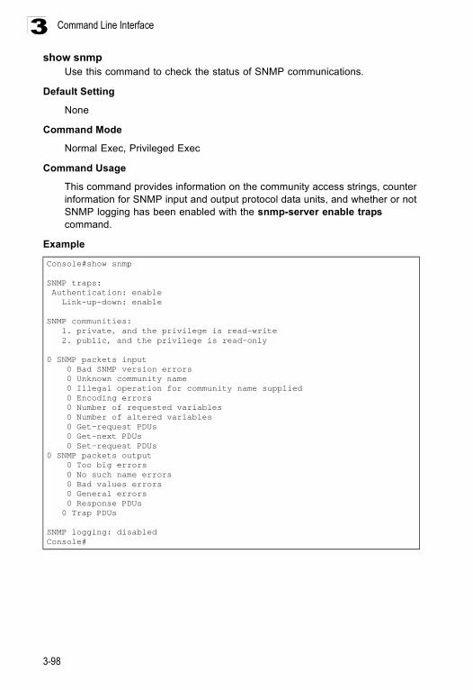
Command Line Interface
3-98
3show snmp
Use this command to check the status of SNMP communications.
Default Setting
None
Command Mode
Normal Exec, Privileged Exec
Command Usage
This command provides information on the community access strings, counter information for SNMP input and output protocol data units, and whether or not SNMP logging has been enabled with the snmp-server enable traps command.
Example
Console#show snmp
SNMP traps: Authentication: enable Link-up-down: enable
SNMP communities: 1. private, and the privilege is read-write 2. public, and the privilege is read-only
0 SNMP packets input 0 Bad SNMP version errors 0 Unknown community name 0 Illegal operation for community name supplied 0 Encoding errors 0 Number of requested variables 0 Number of altered variables 0 Get-request PDUs 0 Get-next PDUs 0 Set-request PDUs0 SNMP packets output 0 Too big errors 0 No such name errors 0 Bad values errors 0 General errors 0 Response PDUs 0 Trap PDUs
SNMP logging: disabledConsole#
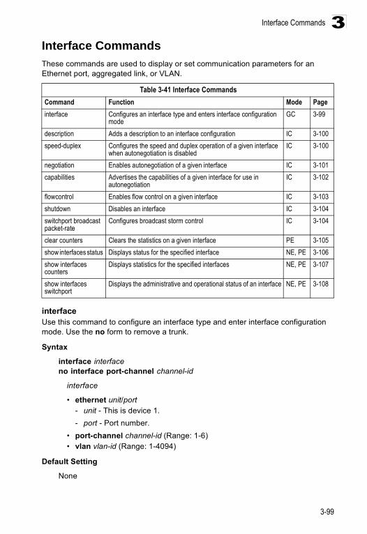
Interface Commands
3-99
3Interface CommandsThese commands are used to display or set communication parameters for an Ethernet port, aggregated link, or VLAN.
interfaceUse this command to configure an interface type and enter interface configuration mode. Use the no form to remove a trunk.
Syntax
interface interfaceno interface port-channel channel-id
interface
• ethernet unit/port- unit - This is device 1. - port - Port number.
• port-channel channel-id (Range: 1-6) • vlan vlan-id (Range: 1-4094)
Default Setting
None
Table 3-41 Interface CommandsCommand Function Mode Pageinterface Configures an interface type and enters interface configuration
mode GC 3-99
description Adds a description to an interface configuration IC 3-100speed-duplex Configures the speed and duplex operation of a given interface
when autonegotiation is disabledIC 3-100
negotiation Enables autonegotiation of a given interface IC 3-101capabilities Advertises the capabilities of a given interface for use in
autonegotiation IC 3-102
flowcontrol Enables flow control on a given interface IC 3-103shutdown Disables an interface IC 3-104switchport broadcast packet-rate
Configures broadcast storm control IC 3-104
clear counters Clears the statistics on a given interface PE 3-105show interfaces status Displays status for the specified interface NE, PE 3-106show interfaces counters
Displays statistics for the specified interfaces NE, PE 3-107
show interfaces switchport
Displays the administrative and operational status of an interface NE, PE 3-108
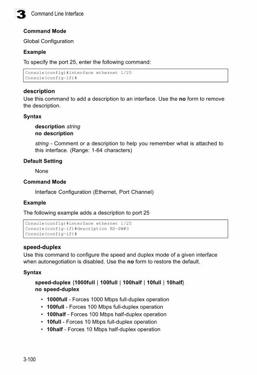
Command Line Interface
3-100
3Command Mode
Global Configuration
Example
To specify the port 25, enter the following command:
descriptionUse this command to add a description to an interface. Use the no form to remove the description.
Syntax
description stringno description
string - Comment or a description to help you remember what is attached to this interface. (Range: 1-64 characters)
Default Setting
None
Command Mode
Interface Configuration (Ethernet, Port Channel)
Example
The following example adds a description to port 25
speed-duplexUse this command to configure the speed and duplex mode of a given interface when autonegotiation is disabled. Use the no form to restore the default.
Syntax
speed-duplex {1000full | 100full | 100half | 10full | 10half}no speed-duplex
• 1000full - Forces 1000 Mbps full-duplex operation • 100full - Forces 100 Mbps full-duplex operation • 100half - Forces 100 Mbps half-duplex operation • 10full - Forces 10 Mbps full-duplex operation • 10half - Forces 10 Mbps half-duplex operation
Console(config)#interface ethernet 1/25Console(config-if)#
Console(config)#interface ethernet 1/25Console(config-if)#description RD-SW#3Console(config-if)#
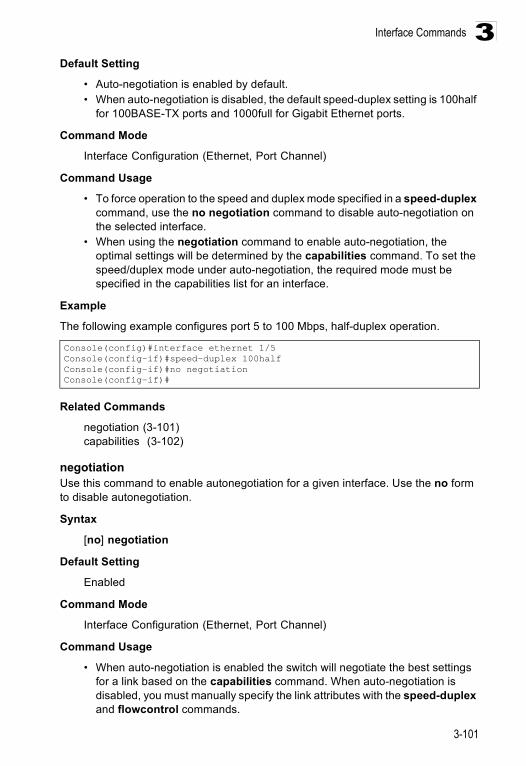
Interface Commands
3-101
3Default Setting
• Auto-negotiation is enabled by default. • When auto-negotiation is disabled, the default speed-duplex setting is 100half
for 100BASE-TX ports and 1000full for Gigabit Ethernet ports.
Command Mode
Interface Configuration (Ethernet, Port Channel)
Command Usage
• To force operation to the speed and duplex mode specified in a speed-duplex command, use the no negotiation command to disable auto-negotiation on the selected interface.
• When using the negotiation command to enable auto-negotiation, the optimal settings will be determined by the capabilities command. To set the speed/duplex mode under auto-negotiation, the required mode must be specified in the capabilities list for an interface.
Example
The following example configures port 5 to 100 Mbps, half-duplex operation.
Related Commands
negotiation (3-101)capabilities (3-102)
negotiationUse this command to enable autonegotiation for a given interface. Use the no form to disable autonegotiation.
Syntax
[no] negotiation
Default Setting
Enabled
Command Mode
Interface Configuration (Ethernet, Port Channel)
Command Usage
• When auto-negotiation is enabled the switch will negotiate the best settings for a link based on the capabilities command. When auto-negotiation is disabled, you must manually specify the link attributes with the speed-duplex and flowcontrol commands.
Console(config)#interface ethernet 1/5Console(config-if)#speed-duplex 100halfConsole(config-if)#no negotiationConsole(config-if)#
Command Line Interface
3-102
3• If autonegotiation is disabled, auto-MDI/MDI-X pin signal configuration will
also be disabled for the RJ-45 ports.
Example
The following example configures port 11 to use autonegotiation
negotiation (3-101)speed-duplex (3-100)
capabilitiesUse this command to advertise the port capabilities of a given interface during autonegotiation. Use the no form with parameters to remove an advertised capability, or the no form without parameters to restore the default values.
Syntax
[no] capabilities {1000full | 100full | 100half | 10full | 10half | flowcontrol | symmetric}
• 1000full - Supports 1000 Mbps full-duplex operation • 100full - Supports 100 Mbps full-duplex operation • 100half - Supports 100 Mbps half-duplex operation • 10full - Supports 10 Mbps full-duplex operation • 10half - Supports 10 Mbps half-duplex operation • flowcontrol - Supports flow control • symmetric (Gigabit only) - When specified, the port transmits and receives
pause frames; when not specified, the port will auto-negotiate to determine the sender and receiver for asymmetric pause frames. (The current switch ASIC only supports symmetric pause frames.)
Default Setting
• 100BASE-TX: 10half, 10full, 100half, 100full• 1000BASE-T: 10half, 10full, 100half, 100full, 1000full• 1000BASE-SX/LX/LH: 1000full
Command Mode
Interface Configuration (Ethernet, Port Channel)
Command Usage
When auto-negotiation is enabled with the negotiation command, the switch will negotiate the best settings for a link based on the capabilites command. When auto-negotiation is disabled, you must manually specify the link attributes with the speed-duplex and flowcontrol commands.
Console(config)#interface ethernet 1/11Console(config-if)#negotiationConsole(config-if)#
Interface Commands
3-103
3Example
The following example configures Ethernet port 5 capabilities to 100half, 100full and flow control
Related Commands
negotiation (3-101)speed-duplex (3-100)flowcontrol (3-103)
flowcontrolUse this command to enable flow control. Use the no form to disable flow control.
Syntax
[no] flowcontrol
Default Setting
Flow control enabled
Command Mode
Interface Configuration (Ethernet, Port Channel)
Command Usage
• Flow control can eliminate frame loss by “blocking” traffic from end stations or segments connected directly to the switch when its buffers fill. When enabled, back pressure is used for half-duplex operation and IEEE 802.3x for full-duplex operation.
• To force flow control on or off (with the flowcontrol or no flowcontrol command), use the no negotiation command to disable auto-negotiation on the selected interface.
• When using the negotiation command to enable auto-negotiation, the optimal settings will be determined by the capabilities command. To enable flow control under auto-negotiation, “flowcontrol” must be included in the capabilities list for any port
• Avoid using flow control on a port connected to a hub unless it is actually required to solve a problem. Otherwise back pressure jamming signals may degrade overall performance for the segment attached to the hub.
Console(config)#interface ethernet 1/5Console(config-if)#capabilities 100halfConsole(config-if)#capabilities 100full Console(config-if)#capabilities flowcontrolConsole(config-if)#
Command Line Interface
3-104
3Example
The following example enables flow control on port 5.
Related Commands
negotiation (3-101)capabilities (flowcontrol, symmetric) (3-102)
shutdown Use this command to disable an interface. To restart a disabled interface, use the no form.
Syntax
[no] shutdown
Default Setting
All interfaces are enabled.
Command Mode
Interface Configuration (Ethernet, Port Channel)
Command Usage
This command allows you to disable a port due to abnormal behavior (e.g., excessive collisions), and then reenable it after the problem has been resolved. You may also want to disable a port for security reasons.
Example
The following example disables port 5.
switchport broadcast packet-rateUse this command to configure broadcast storm control. Use the no form to disable broadcast storm control.
Syntax
switchport broadcast packet-rate rateno switchport broadcast
rate - Threshold level as a rate; i.e., packets per second. (Range: 500 - 262143)
Console(config)#interface ethernet 1/5Console(config-if)#flowcontrolConsole(config-if)#no negotiation Console(config-if)#
Console(config)#interface ethernet 1/5Console(config-if)#shutdownConsole(config-if)#

Interface Commands
3-105
3Default Setting
Enabled for all portsPacket-rate limit: 500 packets per second
Command Mode
Interface Configuration (Ethernet)
Command Usage
• When broadcast traffic exceeds the specified threshold, packets above that threshold are dropped.
• This command can enable or disable broadcast storm control for the selected interface. However, the specified threshold value applies to all ports on the switch.
Example
The following shows how to configure broadcast storm control at 600 packets per second on port 5:
clear countersUse this command to clear statistics on an interface.
Syntax
clear counters interface
interface
• ethernet unit/port- unit - This is device 1. - port - Port number.
• port-channel channel-id (Range: 1-6)
Default Setting
None
Command Mode
Privileged Exec
Command Usage
Statistics are only initialized for a power reset. This command sets the base value for displayed statistics to zero for the current management session. However, if you log out and back into the management interface, the statistics displayed will show the absolute value accumulated since the last power reset.
Console(config)#interface ethernet 1/5Console(config-if)#switchport broadcast packet-rate 600Console(config-if)#
Command Line Interface
3-106
3Example
The following example clears statistics on Ethernet port 1/1
show interfaces statusUse this command to display the status for an interface.
Syntax
show interfaces status [interface]
interface
• ethernet unit/port - unit - This is device 1. - port - Port number.
• port-channel channel-id (Range: 1-6) • vlan vlan-id (Range: 1-4094)
Default Setting
Shows the status for all interfaces.
Command Mode
Normal Exec, Privileged Exec
Command Usage
If no interface is specified, information on all interfaces is displayed. For a description of the items displayed by this command, see “Displaying Connection Status” on page 2-52.
Console#clear counters ethernet 1/1Console#
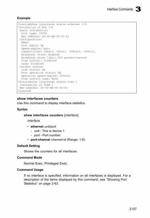
Interface Commands
3-107
3Example
show interfaces countersUse this command to display interface statistics.
Syntax
show interfaces counters [interface]
interface
• ethernet unit/port - unit - This is device 1. - port - Port number.
• port-channel channel-id (Range: 1-6)
Default Setting Shows the counters for all interfaces.
Command Mode
Normal Exec, Privileged Exec
Command Usage
If no interface is specified, information on all interfaces is displayed. For a description of the items displayed by this command, see “Showing Port Statistics” on page 2-63.
Console#show interfaces status ethernet 1/5Information of Eth 1/5 Basic information: Port type: 100TX Mac address: 00-00-AB-CD-00-01 Configuration: Name: Port admin: Up Speed-duplex: Auto Capabilities: 10half, 10full, 100half, 100full, Broadcast storm: Enabled Broadcast storm limit: 500 packets/second Flow control: Disabled Lacp: Disabled Current status: Link status: Up Port operation status: Up Operation speed-duplex: 100full Flow control type: NoneConsole#show interfaces status vlan 1 Information of VLAN 1 MAC address: 00-00-AB-CD-00-00Console#
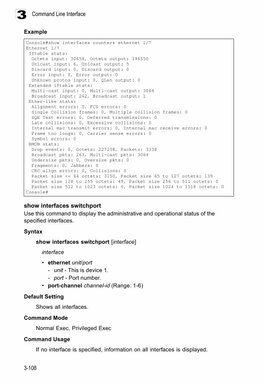
Command Line Interface
3-108
3Example
show interfaces switchportUse this command to display the administrative and operational status of the specified interfaces.
Syntax
show interfaces switchport [interface]
interface
• ethernet unit/port - unit - This is device 1. - port - Port number.
• port-channel channel-id (Range: 1-6)
Default Setting
Shows all interfaces.
Command Mode
Normal Exec, Privileged Exec
Command Usage
If no interface is specified, information on all interfaces is displayed.
Console#show interfaces counters ethernet 1/7Ethernet 1/7 Iftable stats: Octets input: 30658, Octets output: 196550 Unicast input: 6, Unicast output: 5 Discard input: 0, Discard output: 0 Error input: 0, Error output: 0 Unknown protos input: 0, QLen output: 0 Extended iftable stats: Multi-cast input: 0, Multi-cast output: 3064 Broadcast input: 262, Broadcast output: 1 Ether-like stats: Alignment errors: 0, FCS errors: 0 Single Collision frames: 0, Multiple collision frames: 0 SQE Test errors: 0, Deferred transmissions: 0 Late collisions: 0, Excessive collisions: 0 Internal mac transmit errors: 0, Internal mac receive errors: 0 Frame too longs: 0, Carrier sense errors: 0 Symbol errors: 0 RMON stats: Drop events: 0, Octets: 227208, Packets: 3338 Broadcast pkts: 263, Multi-cast pkts: 3064 Undersize pkts: 0, Oversize pkts: 0 Fragments: 0, Jabbers: 0 CRC align errors: 0, Collisions: 0 Packet size <= 64 octets: 3150, Packet size 65 to 127 octets: 139 Packet size 128 to 255 octets: 49, Packet size 256 to 511 octets: 0 Packet size 512 to 1023 octets: 0, Packet size 1024 to 1518 octets: 0Console#

Interface Commands
3-109
3Example This example shows the configuration setting for port 25.
Console#show interfaces switchport ethernet 1/22Information of Eth 1/22 Broadcast threshold: Enabled, 500 packets/second Lacp status: Disabled Ingress rate limit: disable,100M bits per second Egress rate limit: disable,100M bits per second VLAN membership mode: Hybrid Ingress rule: Disabled Acceptable frame type: All frames Native VLAN: 1 Priority for untagged traffic: 0 Gvrp status: Disabled Allowed Vlan: 1(u), Forbidden Vlan:Console#
Field DescriptionBroadcast threshold Shows if broadcast storm suppression is enabled or disabled; if enabled it also
shows the threshold level (See page 3-104.)Lacp status Shows if Link Aggregation Control Protocol has been enabled or disabled (See
page 3-114.)VLAN membership mode Indicates membership mode as Trunk or Hybrid (See page 3-134.)Ingress rule Shows if ingress filtering is enabled or disabled (See page 3-135.)Acceptable frame type Shows if acceptable VLAN frames include all types or tagged frames only (See
page 3-134.)Native VLAN Indicates the default Port VLAN ID (See page 3-136.)Priority for untagged traffic Indicates the default priority for untagged frames (See page 3-144.)Gvrp status Shows if GARP VLAN Registration Protocol is enabled or disabled (See page
3-141.)Allowed Vlan Shows the VLANs this interface has joined, where “(u)” indicates untagged and
“(t)” indicates tagged (See page 3-137.)Forbidden Vlan Shows the VLANs this interface can not dynamically join via GVRP (See page
3-138.)
Command Line Interface
3-110
3Mirror Port CommandsThis section describes how to mirror traffic from a source port to a target port.
port monitorUse this command to configure a mirror session. Use the no form to clear a mirror session.
Syntax
port monitor interface [rx | tx | both]no port monitor interface
• interface - ethernet unit/port (source port) - unit - Switch (unit 1). - port - Port number.
• rx - Mirror received packets. • tx - Mirror transmitted packets. • both - Mirror both received and transmitted packets.
Default Setting
No mirror session is defined. When enabled, the default mirroring is for both received and transmitted packets.
Command Mode
Interface Configuration (Ethernet, destination port)
Command Usage
• You can mirror traffic from any source port to a destination port for real-time analysis. You can then attach a logic analyzer or RMON probe to the destination port and study the traffic crossing the source port in a completely unobtrusive manner.
• The destination port is set by specifying an Ethernet interface. • The mirror port and monitor port speeds should match, otherwise traffic may
be dropped from the monitor port.• You can create multiple mirror sessions, but all sessions must share the same
destination port. However, you should avoid sending too much traffic to the destination port from multiple source ports.
Table 3-42 Mirror Port CommandsCommand Function Mode Pageport monitor Configures a mirror session IC 3-110show port monitor Shows the configuration for a mirror port PE 3-111
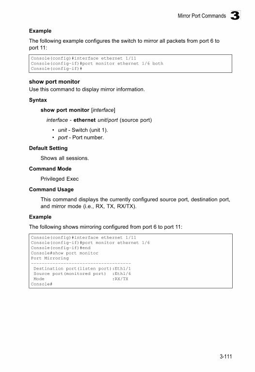
Mirror Port Commands
3-111
3Example
The following example configures the switch to mirror all packets from port 6 to port 11:
show port monitorUse this command to display mirror information.
Syntax
show port monitor [interface]
interface - ethernet unit/port (source port)
• unit - Switch (unit 1). • port - Port number.
Default Setting
Shows all sessions.
Command Mode
Privileged Exec
Command Usage
This command displays the currently configured source port, destination port, and mirror mode (i.e., RX, TX, RX/TX).
Example
The following shows mirroring configured from port 6 to port 11:
Console(config)#interface ethernet 1/11Console(config-if)#port monitor ethernet 1/6 bothConsole(config-if)#
Console(config)#interface ethernet 1/11Console(config-if)#port monitor ethernet 1/6Console(config-if)#endConsole#show port monitorPort Mirroring------------------------------------- Destination port(listen port):Eth1/1 Source port(monitored port) :Eth1/6 Mode :RX/TXConsole#
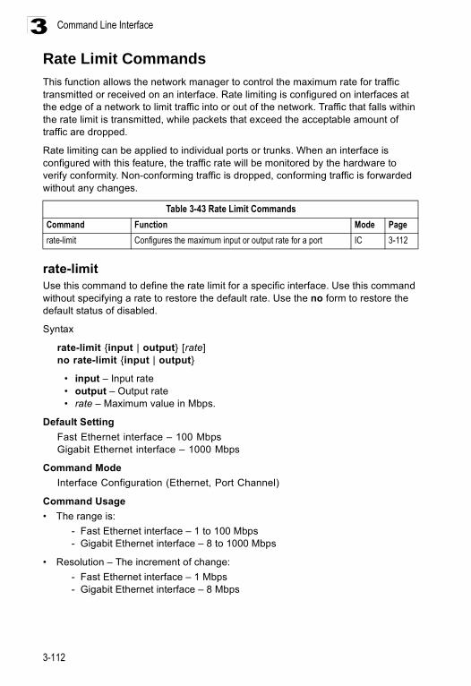
Command Line Interface
3-112
3Rate Limit CommandsThis function allows the network manager to control the maximum rate for traffic transmitted or received on an interface. Rate limiting is configured on interfaces at the edge of a network to limit traffic into or out of the network. Traffic that falls within the rate limit is transmitted, while packets that exceed the acceptable amount of traffic are dropped.
Rate limiting can be applied to individual ports or trunks. When an interface is configured with this feature, the traffic rate will be monitored by the hardware to verify conformity. Non-conforming traffic is dropped, conforming traffic is forwarded without any changes.
rate-limitUse this command to define the rate limit for a specific interface. Use this command without specifying a rate to restore the default rate. Use the no form to restore the default status of disabled.
Syntax
rate-limit {input | output} [rate]no rate-limit {input | output}
• input – Input rate• output – Output rate• rate – Maximum value in Mbps.
Default Setting Fast Ethernet interface – 100 MbpsGigabit Ethernet interface – 1000 Mbps
Command Mode Interface Configuration (Ethernet, Port Channel)
Command Usage• The range is:
- Fast Ethernet interface – 1 to 100 Mbps- Gigabit Ethernet interface – 8 to 1000 Mbps
• Resolution – The increment of change:- Fast Ethernet interface – 1 Mbps- Gigabit Ethernet interface – 8 Mbps
Table 3-43 Rate Limit CommandsCommand Function Mode Pagerate-limit Configures the maximum input or output rate for a port IC 3-112
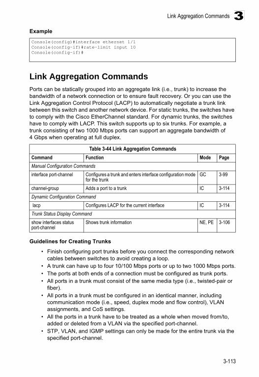
Link Aggregation Commands
3-113
3Example
Link Aggregation Commands Ports can be statically grouped into an aggregate link (i.e., trunk) to increase the bandwidth of a network connection or to ensure fault recovery. Or you can use the Link Aggregation Control Protocol (LACP) to automatically negotiate a trunk link between this switch and another network device. For static trunks, the switches have to comply with the Cisco EtherChannel standard. For dynamic trunks, the switches have to comply with LACP. This switch supports up to six trunks. For example, a trunk consisting of two 1000 Mbps ports can support an aggregate bandwidth of 4 Gbps when operating at full duplex.
Guidelines for Creating Trunks
• Finish configuring port trunks before you connect the corresponding network cables between switches to avoid creating a loop.
• A trunk can have up to four 10/100 Mbps ports or up to two 1000 Mbps ports.• The ports at both ends of a connection must be configured as trunk ports.• All ports in a trunk must consist of the same media type (i.e., twisted-pair or
fiber).• All ports in a trunk must be configured in an identical manner, including
communication mode (i.e., speed, duplex mode and flow control), VLAN assignments, and CoS settings.
• All the ports in a trunk have to be treated as a whole when moved from/to, added or deleted from a VLAN via the specified port-channel.
• STP, VLAN, and IGMP settings can only be made for the entire trunk via the specified port-channel.
Console(config)#interface ethernet 1/1Console(config-if)#rate-limit input 10Console(config-if)#
Table 3-44 Link Aggregation CommandsCommand Function Mode PageManual Configuration Commandsinterface port-channel Configures a trunk and enters interface configuration mode
for the trunk GC 3-99
channel-group Adds a port to a trunk IC 3-114Dynamic Configuration Command lacp Configures LACP for the current interface IC 3-114Trunk Status Display Commandshow interfaces status port-channel
Shows trunk information NE, PE 3-106
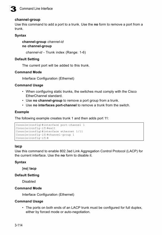
Command Line Interface
3-114
3channel-group Use this command to add a port to a trunk. Use the no form to remove a port from a trunk.
Syntax
channel-group channel-idno channel-group
channel-id - Trunk index (Range: 1-6)
Default Setting
The current port will be added to this trunk.
Command Mode
Interface Configuration (Ethernet)
Command Usage
• When configuring static trunks, the switches must comply with the Cisco EtherChannel standard.
• Use no channel-group to remove a port group from a trunk.• Use no interfaces port-channel to remove a trunk from the switch.
Example
The following example creates trunk 1 and then adds port 11:
lacpUse this command to enable 802.3ad Link Aggregation Control Protocol (LACP) for the current interface. Use the no form to disable it.
Syntax
[no] lacp
Default Setting
Disabled
Command Mode
Interface Configuration (Ethernet)
Command Usage
• The ports on both ends of an LACP trunk must be configured for full duplex, either by forced mode or auto-negotiation.
Console(config)#interface port-channel 1Console(config-if)#exitConsole(config)#interface ethernet 1/11Console(config-if)#channel-group 1Console(config-if)#
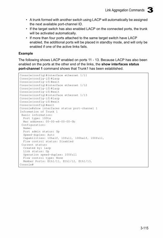
Link Aggregation Commands
3-115
3• A trunk formed with another switch using LACP will automatically be assigned
the next available port-channel ID.• If the target switch has also enabled LACP on the connected ports, the trunk
will be activated automatically. • If more than four ports attached to the same target switch have LACP
enabled, the additional ports will be placed in standby mode, and will only be enabled if one of the active links fails.
Example
The following shows LACP enabled on ports 11 - 13. Because LACP has also been enabled on the ports at the other end of the links, the show interfaces status port-channel 1 command shows that Trunk1 has been established.
Console(config)#interface ethernet 1/11Console(config-if)#lacpConsole(config-if)#exitConsole(config)#interface ethernet 1/12Console(config-if)#lacpConsole(config-if)#exitConsole(config)#interface ethernet 1/13Console(config-if)#lacpConsole(config-if)#exitConsole(config)#exitConsole#show interfaces status port-channel 1Information of Trunk 1 Basic information: Port type: 100tx Mac address: 00-00-e8-00-00-0b Configuration: Name: Port admin status: Up Speed-duplex: Auto Capabilities: 10half, 10full, 100half, 100full, Flow control status: Disabled Current status: Created by: lacp Link status: Up Operation speed-duplex: 100full Flow control type: None Member Ports: Eth1/11, Eth1/12, Eth1/13,Console#
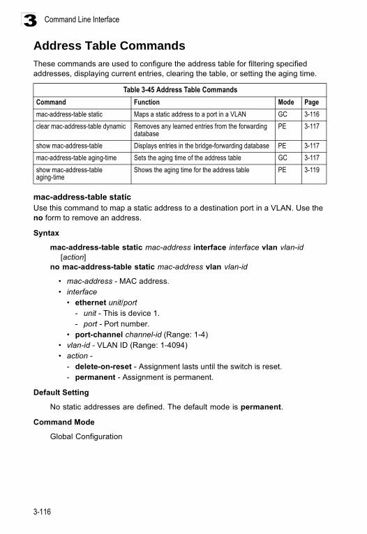
Command Line Interface
3-116
3Address Table CommandsThese commands are used to configure the address table for filtering specified addresses, displaying current entries, clearing the table, or setting the aging time.
mac-address-table staticUse this command to map a static address to a destination port in a VLAN. Use the no form to remove an address.
Syntax
mac-address-table static mac-address interface interface vlan vlan-id [action]no mac-address-table static mac-address vlan vlan-id
• mac-address - MAC address. • interface
• ethernet unit/port- unit - This is device 1. - port - Port number.
• port-channel channel-id (Range: 1-4) • vlan-id - VLAN ID (Range: 1-4094) • action -
- delete-on-reset - Assignment lasts until the switch is reset. - permanent - Assignment is permanent.
Default Setting
No static addresses are defined. The default mode is permanent.
Command Mode
Global Configuration
Table 3-45 Address Table CommandsCommand Function Mode Pagemac-address-table static Maps a static address to a port in a VLAN GC 3-116clear mac-address-table dynamic Removes any learned entries from the forwarding
database PE 3-117
show mac-address-table Displays entries in the bridge-forwarding database PE 3-117mac-address-table aging-time Sets the aging time of the address table GC 3-117show mac-address-table aging-time
Shows the aging time for the address table PE 3-119
Address Table Commands
3-117
3Command Usage
The static address for a host device can be assigned to a specific port within a specific VLAN. Use this command to add static addresses to the MAC Address Table. Static addresses have the following characteristics:
• Static addresses will not be removed from the address table when a given interface link is down.
• Static addresses are bound to the assigned interface and will not be moved. When a static address is seen on another interface, the address will be ignored and will not be written to the address table.
• A static address cannot be learned on another port until the address is removed with the no form of this command.
Example
clear mac-address-table dynamicUse this command to remove any learned entries from the forwarding database and to clear the transmit and receive counts for any static or system configured entries.
Default Setting
None
Command Mode
Privileged Exec
Example
show mac-address-tableUse this command to view classes of entries in the bridge-forwarding database.
Syntax
show mac-address-table [address mac-address [mask]] [interface interface] [vlan vlan-id] [sort {address | vlan | interface}]
• mac-address - MAC address.• mask - Bits to match in the address. • interface
• ethernet unit/port- unit - This is device 1. - port - Port number.
• port-channel channel-id (Range: 1-4) • vlan-id - VLAN ID (Range: 1-4094) • sort - Sort by address, vlan or interface.
Console(config)#mac-address-table static 00-e0-29-94-34-de interface ethernet 1/1 vlan 1 delete-on-reset
Console#clear mac-address-table dynamic
Command Line Interface
3-118
3Default Setting
None
Command Mode
Privileged Exec
Command Usage
• The MAC Address Table contains the MAC addresses associated with each interface. Note that the Type field may include the following types:- Learned - Dynamic address entries- Permanent - Static entry- Delete-on-reset - Static entry to be deleted when system is reset
• The mask should be hexadecimal numbers (representing an equivalent bit mask) in the form xx-xx-xx-xx-xx-xx that is applied to the specified MAC address. Enter hexadecimal numbers, where an equivalent binary bit “0” means to match a bit and “1” means to ignore a bit. For example, a mask of 00-00-00-00-00-00 means an exact match, and a mask of FF-FF-FF-FF-FF-FF means “any.”
• The maximum number of address entries is 8191.
Example
mac-address-table aging-timeUse this command to set the aging time for entries in the address table. Use the no form to restore the default aging time.
Syntax
mac-address-table aging-time secondsno mac-address-table aging-time
seconds - Time in number of seconds (10-1000000).
Default Setting
300 seconds
Command Mode
Global Configuration
Command Usage
The aging time is used to age out dynamically learned forwarding information.
Console#show mac-address-table Interface Mac Address Vlan Type --------- ----------------- ---- ----------------- Eth 1/ 1 00-E0-29-94-34-DE 1 Delete-on-reset Console#
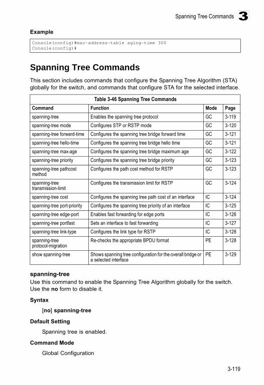
Spanning Tree Commands
3-119
3Example
Spanning Tree CommandsThis section includes commands that configure the Spanning Tree Algorithm (STA) globally for the switch, and commands that configure STA for the selected interface.
spanning-treeUse this command to enable the Spanning Tree Algorithm globally for the switch. Use the no form to disable it.
Syntax
[no] spanning-tree
Default Setting
Spanning tree is enabled.
Command Mode
Global Configuration
Console(config)#mac-address-table aging-time 300Console(config)#
Table 3-46 Spanning Tree CommandsCommand Function Mode Pagespanning-tree Enables the spanning tree protocol GC 3-119spanning-tree mode Configures STP or RSTP mode GC 3-120spanning-tree forward-time Configures the spanning tree bridge forward time GC 3-121spanning-tree hello-time Configures the spanning tree bridge hello time GC 3-121spanning-tree max-age Configures the spanning tree bridge maximum age GC 3-122spanning-tree priority Configures the spanning tree bridge priority GC 3-123spanning-tree pathcost method
Configures the path cost method for RSTP GC 3-123
spanning-tree transmission-limit
Configures the transmission limit for RSTP GC 3-124
spanning-tree cost Configures the spanning tree path cost of an interface IC 3-124spanning-tree port-priority Configures the spanning tree priority of an interface IC 3-125spanning-tree edge-port Enables fast forwarding for edge ports IC 3-126spanning-tree portfast Sets an interface to fast forwarding IC 3-127spanning-tree link-type Configures the link type for RSTP IC 3-128spanning-tree protocol-migration
Re-checks the appropriate BPDU format PE 3-128
show spanning-tree Shows spanning tree configuration for the overall bridge or a selected interface
PE 3-129
Command Line Interface
3-120
3Command Usage
The Spanning Tree Algorithm (STA) can be used to detect and disable network loops, and to provide backup links between switches, bridges or routers. This allows the switch to interact with other bridging devices (that is, an STA-compliant switch, bridge or router) in your network to ensure that only one route exists between any two stations on the network, and provide backup links which automatically take over when a primary link goes down.
Example
This example shows how to enable the Spanning Tree Algorithm for the switch:
spanning-tree modeUse this command to select the spanning tree mode for this switch. Use the no form to restore the default.
Syntax
spanning-tree mode {stp | rstp}no spanning-tree mode
• stp - Spanning Tree Protocol (IEEE 802.1D)• rstp - Rapid Spanning Tree (IEEE 802.1w)
Default Setting
rstp
Command Mode
Global Configuration
Command Usage
• Spanning Tree Protocol
Uses RSTP for the internal state machine, but sends only 802.1D BPDUs.
• Rapid Spanning Tree Protocol
RSTP supports connections to either STP or RSTP nodes by monitoring the incoming protocol messages and dynamically adjusting the type of protocol messages the RSTP node transmits, as described below:
- STP Mode – If the switch receives an 802.1D BPDU after a port’s migration delay timer expires, the switch assumes it is connected to an 802.1D bridge and starts using only 802.1D BPDUs.
- RSTP Mode – If RSTP is using 802.1D BPDUs on a port and receives an RSTP BPDU after the migration delay expires, RSTP restarts the migration delay timer and begins using RSTP BPDUs on that port.
Console(config)#spanning-treeConsole(config)#
Spanning Tree Commands
3-121
3Example
The following example configures the switch to use Rapid Spanning Tree.
spanning-tree forward-timeUse this command to configure the spanning tree bridge forward time globally for this switch. Use the no form to restore the default.
Syntax
spanning-tree forward-time secondsno spanning-tree forward-time
seconds - Time in seconds. (Range: 4 - 30 seconds)The minimum value is the higher of 4 or [(max-age / 2) + 1].
Default Setting
15 seconds
Command Mode
Global Configuration
Command Usage
This command sets the maximum time (in seconds) the root device will wait before changing states (i.e., discarding to learning to forwarding). This delay is required because every device must receive information about topology changes before it starts to forward frames. In addition, each port needs time to listen for conflicting information that would make it return to a blocking state; otherwise, temporary data loops might result.
Example
spanning-tree hello-timeUse this command to configure the spanning tree bridge hello time globally for this switch. Use the no form to restore the default.
Syntax
spanning-tree hello-time timeno spanning-tree hello-time
time - Time in seconds, (Range: 1 - 10 seconds). The maximum value is the lower of 10 or [(max-age / 2) -1].
Default Setting
2 seconds
Console(config)#spanning-tree mode rstpConsole(config)#
Console(config)#spanning-tree forward-time 20Console(config)#
Command Line Interface
3-122
3Command Mode
Global Configuration
Command Usage
This command sets the time interval (in seconds) at which the root device transmits a configuration message.
Example
spanning-tree max-ageUse this command to configure the spanning tree bridge maximum age globally for this switch. Use the no form to restore the default.
Syntax
spanning-tree max-age secondsno spanning-tree max-age
seconds - Time in seconds. (Range: 6-40 seconds)The minimum value is the higher of 6 or [2 x (hello-time + 1)].The maximum value is the lower of 40 or [2 x (forward-time - 1)].
Default Setting
20 seconds
Command Mode
Global Configuration
Command Usage
This command sets the maximum time (in seconds) a device can wait without receiving a configuration message before attempting to reconfigure. All device ports (except for designated ports) should receive configuration messages at regular intervals. Any port that ages out STA information (provided in the last configuration message) becomes the designated port for the attached LAN. If it is a root port, a new root port is selected from among the device ports attached to the network.
Example
Console(config)#spanning-tree hello-time 5Console(config)#
Console(config)#spanning-tree max-age 40Console(config)#
Spanning Tree Commands
3-123
3spanning-tree priorityUse this command to configure the spanning tree priority globally for this switch. Use the no form to restore the default.
Syntax
spanning-tree priority priority no spanning-tree priority
priority - Priority of the bridge. (Range: 0 - 65535) (Range – 0-61440, in steps of 4096; Options: 0, 4096, 8192, 12288, 16384, 20480, 24576, 28672, 32768, 36864, 40960, 45056, 49152, 53248, 57344, 61440)
Default Setting
32768
Command Mode
Global Configuration
Command Usage
Bridge priority is used in selecting the root device, root port, and designated port. The device with the highest priority becomes the STA root device. However, if all devices have the same priority, the device with the lowest MAC address will then become the root device.
Example
spanning-tree pathcost methodUse this command to configure the path cost method used for Rapid Spanning Tree. Use the no form to restore the default.
Syntax
spanning-tree pathcost method {long | short} no spanning-tree pathcost method
• long - Specifies 32-bit based values that range from 1-200,000,000.• short - Specifies 16-bit based values that range from 1-65535.
Default Setting
Long method
Command Mode
Global Configuration
Console(config)#spanning-tree priority 40000Console(config)#
Command Line Interface
3-124
3Command Usage
The path cost method is used to determine the best path between devices. Therefore, lower values should be assigned to ports attached to faster media, and higher values assigned to ports with slower media. Note that path cost (page 3-123) takes precedence over port priority (page 3-125).
Example
spanning-tree transmission-limitUse this command to configure the minimum interval between the transmission of consecutive RSTP BPDUs. Use the no form to restore the default.
Syntax
spanning-tree transmission-limit count no spanning-tree transmission-limit
count -The transmission limit in seconds. (Range: 1-10)
Default
3
Command Mode
Global Configuration
Command Usage
This command limits the maximum transmission rate for BPDUs.
Example
spanning-tree cost Use this command to configure the spanning tree path cost for the specified interface. Use the no form to restore the default.
Syntax
spanning-tree cost costno spanning-tree cost
cost - The path cost for the port. (Range: 1-200,000,000))The recommended range is:
• Ethernet: 200,000-20,000,000• Fast Ethernet: 20,000-2,000,000• Gigabit Ethernet: 2,000-200,000
Console (config)# spanning-tree pathcost method longConsole (config)#
Console(config)#spanning-tree transmission-limit 4Console(config)#
Spanning Tree Commands
3-125
3Default Setting
• Ethernet – half duplex: 2,000,000; full duplex: 1,000,000; trunk: 500,000• Fast Ethernet – half duplex: 200,000; full duplex: 100,000; trunk: 50,000• Gigabit Ethernet – full duplex: 10,000; trunk: 5,000
Command Mode
Interface Configuration (Ethernet, Port Channel)
Command Usage
• This command is used by the Spanning Tree Algorithm to determine the best path between devices. Therefore, lower values should be assigned to ports attached to faster media, and higher values assigned to ports with slower media.
• Path cost takes precedence over port priority.• When the spanning-tree pathcost method (page 3-123) is set to short, the
maximum value for path cost is 65,535.
Example
spanning-tree port-priority Use this command to configure the priority for the specified interface. Use the no form to restore the default.
Syntax
spanning-tree port-priority priorityno spanning-tree port-priority
priority - The priority for a port. (Range: 0-240, in steps of 16)
Default Setting
128
Command Mode
Interface Configuration (Ethernet, Port Channel)
Command Usage
• This command defines the priority for the use of a port in the Spanning Tree Algorithm. If the path cost for all ports on a switch are the same, the port with the highest priority (that is, lowest value) will be configured as an active link in the spanning tree.
• Where more than one port is assigned the highest priority, the port with the lowest numeric identifier will be enabled.
Console(config)#interface ethernet 1/5Console(config-if)#spanning-tree cost 50Console(config-if)#
Command Line Interface
3-126
3Example
Related Commands
spanning-tree cost (3-124)
spanning-tree edge-port Use this command to specify an interface as an edge port. Use the no form to restore the default.
Syntax
[no] spanning-tree edge-port
Default Setting
Disabled
Command Mode
Interface Configuration (Ethernet, Port Channel)
Command Usage
• You can enable this option if an interface is attached to a LAN segment that is at the end of a bridged LAN or to an end node. Since end nodes cannot cause forwarding loops, they can pass directly through to the spanning tree forwarding state. Specifying Edge Ports provides quicker convergence for devices such as workstations or servers, retains the current forwarding database to reduce the amount of frame flooding required to rebuild address tables during reconfiguration events, does not cause the spanning tree to initiate reconfiguration when the interface changes state, and also overcomes other STA-related timeout problems. However, remember that Edge Port should only be enabled for ports connected to an end-node device.
• This command has the same effect as the spanning-tree portfast.
Example
Related Commands
spanning-tree portfast (3-127)
Console(config)#interface ethernet 1/5Console(config-if)#spanning-tree port-priority 0Console(config-if)#
Console(config)#interface ethernet 1/5Console(config-if)#spanning-tree edge-portConsole(config-if)#
Spanning Tree Commands
3-127
3spanning-tree portfastUse this command to set an interface to fast forwarding. Use the no form to disable fast forwarding.
Syntax
[no] spanning-tree portfast
Default Setting
Disabled
Command Mode
Interface Configuration (Ethernet, Port Channel)
Command Usage
• This command is used to enable/disable the fast spanning-tree mode for the selected port. In this mode, ports skip the Discarding and Learning states, and proceed straight to Forwarding.
• Since end-nodes cannot cause forwarding loops, they can be passed through the spanning tree state changes more quickly than allowed by standard convergence time. Fast forwarding can achieve quicker convergence for end-node workstations and servers, and also overcome other STA related timeout problems. (Remember that fast forwarding should only be enabled for ports connected to a LAN segment that is at the end of a bridged LAN or for an end-node device.)
• This command is the same as spanning-tree edge-port, and is only included for backward compatibility with earlier products. Note that this command may be removed for future software versions.
Example
Related Commands
spanning-tree edge-port (3-126)
Console(config)#interface ethernet 1/5Console(config-if)#spanning-tree portfastConsole(config-if)#
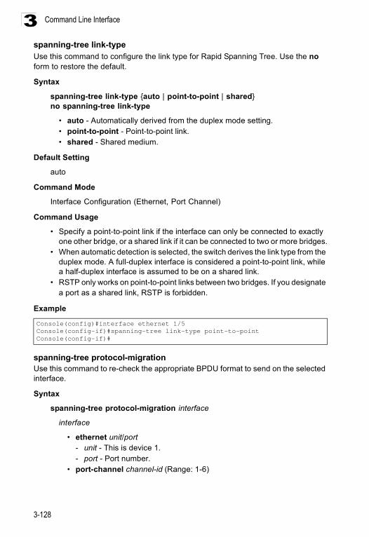
Command Line Interface
3-128
3spanning-tree link-typeUse this command to configure the link type for Rapid Spanning Tree. Use the no form to restore the default.
Syntax
spanning-tree link-type {auto | point-to-point | shared}no spanning-tree link-type
• auto - Automatically derived from the duplex mode setting. • point-to-point - Point-to-point link.• shared - Shared medium.
Default Setting
auto
Command Mode
Interface Configuration (Ethernet, Port Channel)
Command Usage
• Specify a point-to-point link if the interface can only be connected to exactly one other bridge, or a shared link if it can be connected to two or more bridges.
• When automatic detection is selected, the switch derives the link type from the duplex mode. A full-duplex interface is considered a point-to-point link, while a half-duplex interface is assumed to be on a shared link.
• RSTP only works on point-to-point links between two bridges. If you designate a port as a shared link, RSTP is forbidden.
Example
spanning-tree protocol-migrationUse this command to re-check the appropriate BPDU format to send on the selected interface.
Syntax
spanning-tree protocol-migration interface
interface
• ethernet unit/port- unit - This is device 1. - port - Port number.
• port-channel channel-id (Range: 1-6)
Console(config)#interface ethernet 1/5Console(config-if)#spanning-tree link-type point-to-pointConsole(config-if)#
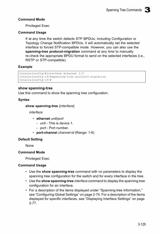
Spanning Tree Commands
3-129
3Command Mode
Privileged Exec
Command Usage
If at any time the switch detects STP BPDUs, including Configuration or Topology Change Notification BPDUs, it will automatically set the selected interface to forced STP-compatible mode. However, you can also use the spanning-tree protocol-migration command at any time to manually re-check the appropriate BPDU format to send on the selected interfaces (i.e., RSTP or STP-compatible).
Example
show spanning-treeUse this command to show the spanning tree configuration.
Syntax
show spanning-tree [interface]
interface
• ethernet unit/port - unit - This is device 1. - port - Port number.
• port-channel channel-id (Range: 1-6)
Default Setting
None
Command Mode
Privileged Exec
Command Usage
• Use the show spanning-tree command with no parameters to display the spanning tree configuration for the switch and for every interface in the tree.
• Use the show spanning-tree interface command to display the spanning tree configuration for an interface.
• For a description of the items displayed under “Spanning-tree information,” see “Configuring Global Settings” on page 2-74. For a description of the items displayed for specific interfaces, see “Displaying Interface Settings” on page 2-77.
Console(config)#interface ethernet 1/5Console(config-if)#spanning-tree protocol-migrationConsole(config-if)#
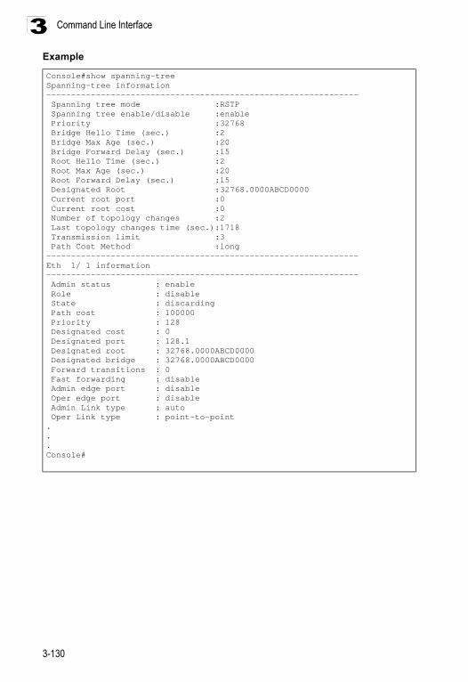
Command Line Interface
3-130
3Example
Console#show spanning-treeSpanning-tree information--------------------------------------------------------------- Spanning tree mode :RSTP Spanning tree enable/disable :enable Priority :32768 Bridge Hello Time (sec.) :2 Bridge Max Age (sec.) :20 Bridge Forward Delay (sec.) :15 Root Hello Time (sec.) :2 Root Max Age (sec.) :20 Root Forward Delay (sec.) :15 Designated Root :32768.0000ABCD0000 Current root port :0 Current root cost :0 Number of topology changes :2 Last topology changes time (sec.):1718 Transmission limit :3 Path Cost Method :long---------------------------------------------------------------Eth 1/ 1 information--------------------------------------------------------------- Admin status : enable Role : disable State : discarding Path cost : 100000 Priority : 128 Designated cost : 0 Designated port : 128.1 Designated root : 32768.0000ABCD0000 Designated bridge : 32768.0000ABCD0000 Forward transitions : 0 Fast forwarding : disable Admin edge port : disable Oper edge port : disable Admin Link type : auto Oper Link type : point-to-point...Console#
VLAN Commands
3-131
3VLAN CommandsA VLAN is a group of ports that can be located anywhere in the network, but communicate as though they belong to the same physical segment. This section describes commands used to create VLAN groups, add port members, specify how VLAN tagging is used, and enable automatic VLAN registration for the selected interface.
Editing VLAN Groups
vlan databaseUse this command to enter VLAN database mode. All commands in this mode will take effect immediately.
Default Setting
None
Command Mode
Global Configuration
Command Usage
• Use the VLAN database command mode to add, change, and delete VLANs. After finishing configuration changes, you can display the VLAN settings by entering the show vlan command.
• Use the interface vlan command mode to define the port membership mode and add or remove ports from a VLAN. The results of these commands are written to the running-configuration file, and you can display this file by entering the show running-config command.
Table 3-47 VLAN CommandsCommand Groups Function PageEditing VLAN Groups Sets up VLAN groups, including name, VID and state 3-131Configuring VLAN Interfaces
Configures VLAN interface parameters, including ingress and egress tagging mode, ingress filtering, PVID, and GVRP
3-133
Displaying VLAN Information
Displays VLAN groups, status, port members, and MAC addresses 3-138
Table 3-48 Editing VLAN GroupsCommand Function Mode Pagevlan database Enters VLAN database mode to add, change, and delete
VLANs GC 3-131
vlan Configures a VLAN, including VID, name and state VC 3-132
Command Line Interface
3-132
3Example
Related Commands
show vlan (3-139)
vlanUse this command to configure a VLAN. Use the no form to restore the default settings or delete a VLAN.
Syntax
vlan vlan-id [name vlan-name] media ethernet [state {active | suspend}]no vlan vlan-id [name | state]
• vlan-id - ID of configured VLAN. (Range: 1-4094, no leading zeroes) • name - Keyword to be followed by the VLAN name.
- vlan-name - ASCII string from 1 to 32 characters. • media ethernet - Ethernet media type. • state - Keyword to be followed by the VLAN state.
- active - VLAN is operational. - suspend - VLAN is suspended. Suspended VLANs do not pass packets.
Default Setting
By default only VLAN 1 exists and is active.
Command Mode
VLAN Database Configuration
Command Usage
• no vlan vlan-id deletes the VLAN. • no vlan vlan-id name removes the VLAN name. • no vlan vlan-id state returns the VLAN to the default state (i.e., active). • You can configure up to 255 VLANs on the switch.
Example
The following example adds a VLAN, using VLAN ID 105 and name RD5. The VLAN is activated by default.
Related Commands
show vlan (3-139)
Console(config)#vlan databaseConsole(config-vlan)#
Console(config)#vlan databaseConsole(config-vlan)#vlan 105 name RD5 media ethernetConsole(config-vlan)#
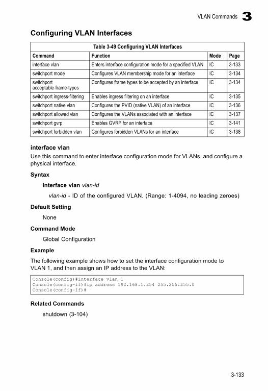
VLAN Commands
3-133
3Configuring VLAN Interfaces
interface vlanUse this command to enter interface configuration mode for VLANs, and configure a physical interface.
Syntax
interface vlan vlan-id
vlan-id - ID of the configured VLAN. (Range: 1-4094, no leading zeroes)
Default Setting
None
Command Mode
Global Configuration
Example
The following example shows how to set the interface configuration mode to VLAN 1, and then assign an IP address to the VLAN:
Related Commands
shutdown (3-104)
Table 3-49 Configuring VLAN InterfacesCommand Function Mode Pageinterface vlan Enters interface configuration mode for a specified VLAN IC 3-133switchport mode Configures VLAN membership mode for an interface IC 3-134switchport acceptable-frame-types
Configures frame types to be accepted by an interface IC 3-134
switchport ingress-filtering Enables ingress filtering on an interface IC 3-135switchport native vlan Configures the PVID (native VLAN) of an interface IC 3-136switchport allowed vlan Configures the VLANs associated with an interface IC 3-137switchport gvrp Enables GVRP for an interface IC 3-141switchport forbidden vlan Configures forbidden VLANs for an interface IC 3-138
Console(config)#interface vlan 1Console(config-if)#ip address 192.168.1.254 255.255.255.0Console(config-if)#
Command Line Interface
3-134
3switchport mode Use this command to configure the VLAN membership mode for a port. Use the no form to restore the default.
Syntax
switchport mode {trunk | hybrid}no switchport mode
• trunk - Specifies a port as an end-point for a VLAN trunk. A trunk is a direct link between two switches, so the port transmits tagged frames that identify the source VLAN. However, note that frames belonging to the port’s default VLAN (i.e., associated with the PVID) are sent untagged.
• hybrid - Specifies a hybrid VLAN interface. The port may transmit tagged or untagged frames.
Default Setting
All ports are in hybrid mode with the PVID set to VLAN 1.
Command Mode
Interface Configuration (Ethernet, Port Channel)
Example
The following shows how to set the configuration mode to port 1, and then set the switchport mode to hybrid:
Related Commands
switchport acceptable-frame-types (3-134)
switchport acceptable-frame-typesUse this command to configure the acceptable frame types for a port. Use the no form to restore the default.
Syntax
switchport acceptable-frame-types {all | tagged}no switchport acceptable-frame-types
• all - The port accepts all frames, tagged or untagged. • tagged - The port only passes tagged frames.
Default Setting
All frame types
Console(config)#interface ethernet 1/1Console(config-if)#switchport mode hybridConsole(config-if)#
VLAN Commands
3-135
3Command Mode
Interface Configuration (Ethernet, Port Channel)
Command Usage
When set to receive all frame types, any received frames that are untagged are assigned to the default VLAN.
Example
The following example shows how to restrict the traffic passed on port 1 to tagged frames:
Related Commands
switchport mode (3-134)
switchport ingress-filteringUse this command to enable ingress filtering for an interface. Use the no form to restore the default.
Syntax
[no] switchport ingress-filtering
Default Setting
Disabled
Command Mode
Interface Configuration (Ethernet, Port Channel)
Command Usage
• Ingress filtering only affects tagged frames.• If ingress filtering is disabled and a port receives frames tagged for VLANs for
which it is not a member, these frames will be flooded to all other ports (except for those VLANs explicitly forbidden on this port).
• If ingress filtering is enabled and a port receives frames tagged for VLANs for which it is not a member, these frames will be discarded.
• Ingress filtering does not affect VLAN independent BPDU frames, such as GVRP or STA. However, they do affect VLAN dependent BPDU frames, such as GMRP.
Console(config)#interface ethernet 1/1Console(config-if)#switchport acceptable-frame-types taggedConsole(config-if)#
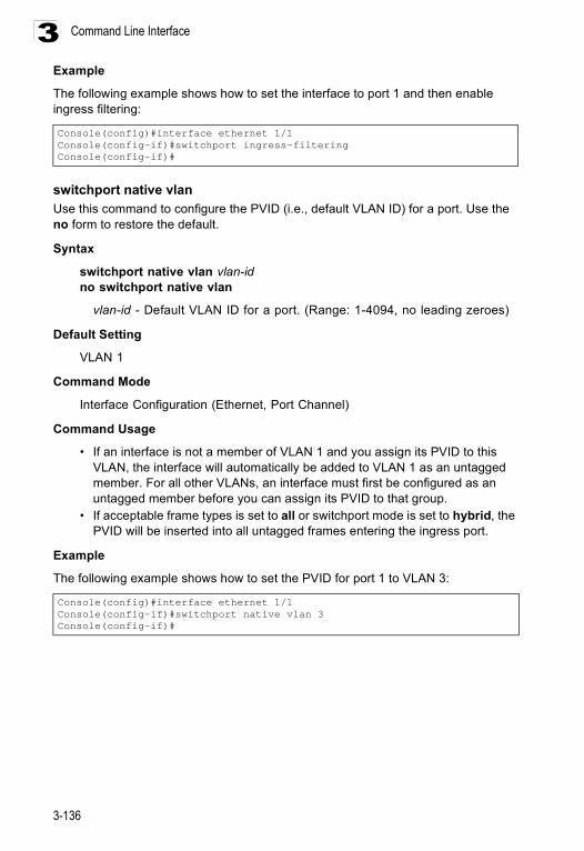
Command Line Interface
3-136
3Example
The following example shows how to set the interface to port 1 and then enable ingress filtering:
switchport native vlanUse this command to configure the PVID (i.e., default VLAN ID) for a port. Use the no form to restore the default.
Syntax
switchport native vlan vlan-idno switchport native vlan
vlan-id - Default VLAN ID for a port. (Range: 1-4094, no leading zeroes)
Default Setting
VLAN 1
Command Mode
Interface Configuration (Ethernet, Port Channel)
Command Usage
• If an interface is not a member of VLAN 1 and you assign its PVID to this VLAN, the interface will automatically be added to VLAN 1 as an untagged member. For all other VLANs, an interface must first be configured as an untagged member before you can assign its PVID to that group.
• If acceptable frame types is set to all or switchport mode is set to hybrid, the PVID will be inserted into all untagged frames entering the ingress port.
Example
The following example shows how to set the PVID for port 1 to VLAN 3:
Console(config)#interface ethernet 1/1Console(config-if)#switchport ingress-filteringConsole(config-if)#
Console(config)#interface ethernet 1/1Console(config-if)#switchport native vlan 3Console(config-if)#
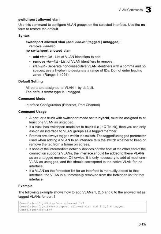
VLAN Commands
3-137
3switchport allowed vlanUse this command to configure VLAN groups on the selected interface. Use the no form to restore the default.
Syntax
switchport allowed vlan {add vlan-list [tagged | untagged] | remove vlan-list}
no switchport allowed vlan
• add vlan-list - List of VLAN identifiers to add. • remove vlan-list - List of VLAN identifiers to remove. • vlan-list - Separate nonconsecutive VLAN identifiers with a comma and no
spaces; use a hyphen to designate a range of IDs. Do not enter leading zeros. (Range: 1-4094).
Default Setting
All ports are assigned to VLAN 1 by default.The default frame type is untagged.
Command Mode
Interface Configuration (Ethernet, Port Channel)
Command Usage
• A port, or a trunk with switchport mode set to hybrid, must be assigned to at least one VLAN as untagged.
• If a trunk has switchport mode set to trunk (i.e., 1Q Trunk), then you can only assign an interface to VLAN groups as a tagged member.
• Frames are always tagged within the switch. The tagged/untagged parameter used when adding a VLAN to an interface tells the switch whether to keep or remove the tag from a frame on egress.
• If none of the intermediate network devices nor the host at the other end of the connection supports VLANs, the interface should be added to these VLANs as an untagged member. Otherwise, it is only necessary to add at most one VLAN as untagged, and this should correspond to the native VLAN for the interface.
• If a VLAN on the forbidden list for an interface is manually added to that interface, the VLAN is automatically removed from the forbidden list for that interface.
Example
The following example shows how to add VLANs 1, 2, 5 and 6 to the allowed list as tagged VLANs for port 1:
Console(config)#interface ethernet 1/1Console(config-if)#switchport allowed vlan add 1,2,5,6 taggedConsole(config-if)#
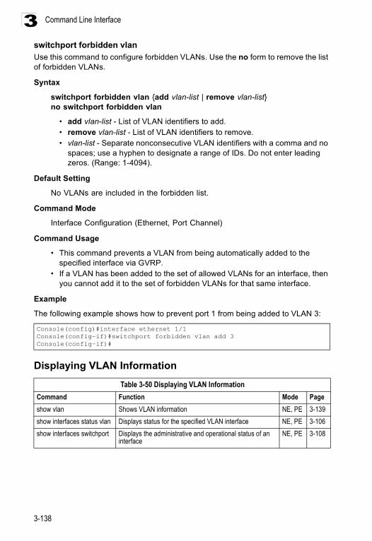
Command Line Interface
3-138
3switchport forbidden vlanUse this command to configure forbidden VLANs. Use the no form to remove the list of forbidden VLANs.
Syntax
switchport forbidden vlan {add vlan-list | remove vlan-list}no switchport forbidden vlan
• add vlan-list - List of VLAN identifiers to add. • remove vlan-list - List of VLAN identifiers to remove.• vlan-list - Separate nonconsecutive VLAN identifiers with a comma and no
spaces; use a hyphen to designate a range of IDs. Do not enter leading zeros. (Range: 1-4094).
Default Setting
No VLANs are included in the forbidden list.
Command Mode
Interface Configuration (Ethernet, Port Channel)
Command Usage
• This command prevents a VLAN from being automatically added to the specified interface via GVRP.
• If a VLAN has been added to the set of allowed VLANs for an interface, then you cannot add it to the set of forbidden VLANs for that same interface.
Example
The following example shows how to prevent port 1 from being added to VLAN 3:
Displaying VLAN Information
Console(config)#interface ethernet 1/1Console(config-if)#switchport forbidden vlan add 3Console(config-if)#
Table 3-50 Displaying VLAN InformationCommand Function Mode Pageshow vlan Shows VLAN information NE, PE 3-139show interfaces status vlan Displays status for the specified VLAN interface NE, PE 3-106show interfaces switchport Displays the administrative and operational status of an
interfaceNE, PE 3-108
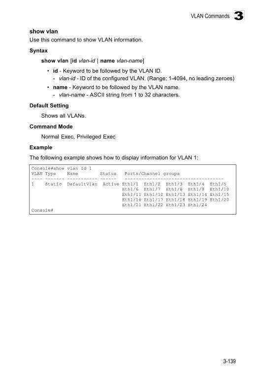
VLAN Commands
3-139
3show vlanUse this command to show VLAN information.
Syntax
show vlan [id vlan-id | name vlan-name]
• id - Keyword to be followed by the VLAN ID. - vlan-id - ID of the configured VLAN. (Range: 1-4094, no leading zeroes)
• name - Keyword to be followed by the VLAN name. - vlan-name - ASCII string from 1 to 32 characters.
Default Setting
Shows all VLANs.
Command Mode
Normal Exec, Privileged Exec
Example
The following example shows how to display information for VLAN 1:
Console#show vlan id 1VLAN Type Name Status Ports/Channel groups---- ------- ----------- ------ ------------------------------------1 Static DefaultVlan Active Eth1/1 Eth1/2 Eth1/3 Eth1/4 Eth1/5 Eth1/6 Eth1/7 Eth1/8 Eth1/9 Eth1/10 Eth1/11 Eth1/12 Eth1/13 Eth1/14 Eth1/15 Eth1/16 Eth1/17 Eth1/18 Eth1/19 Eth1/20 Eth1/21 Eth1/22 Eth1/23 Eth1/24Console#
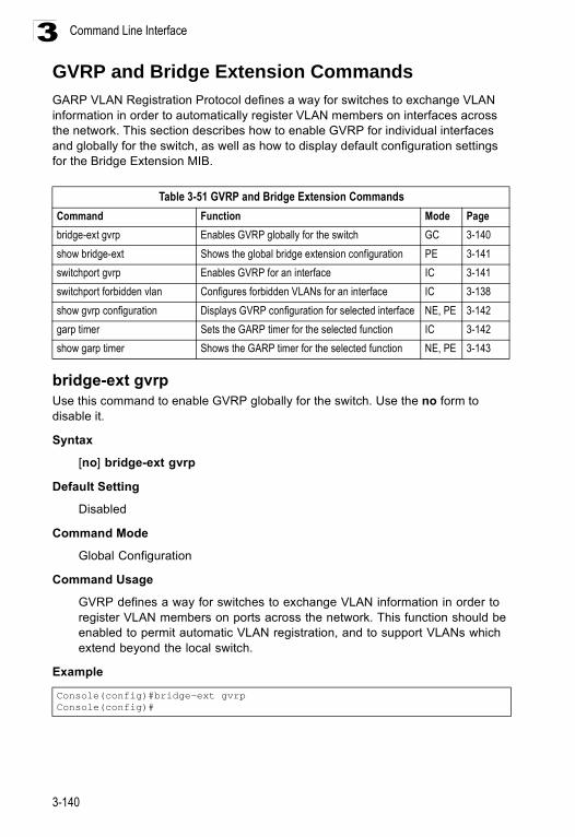
Command Line Interface
3-140
3GVRP and Bridge Extension CommandsGARP VLAN Registration Protocol defines a way for switches to exchange VLAN information in order to automatically register VLAN members on interfaces across the network. This section describes how to enable GVRP for individual interfaces and globally for the switch, as well as how to display default configuration settings for the Bridge Extension MIB.
bridge-ext gvrpUse this command to enable GVRP globally for the switch. Use the no form to disable it.
Syntax
[no] bridge-ext gvrp
Default Setting
Disabled
Command Mode
Global Configuration
Command Usage
GVRP defines a way for switches to exchange VLAN information in order to register VLAN members on ports across the network. This function should be enabled to permit automatic VLAN registration, and to support VLANs which extend beyond the local switch.
Example
Table 3-51 GVRP and Bridge Extension CommandsCommand Function Mode Pagebridge-ext gvrp Enables GVRP globally for the switch GC 3-140show bridge-ext Shows the global bridge extension configuration PE 3-141switchport gvrp Enables GVRP for an interface IC 3-141switchport forbidden vlan Configures forbidden VLANs for an interface IC 3-138show gvrp configuration Displays GVRP configuration for selected interface NE, PE 3-142garp timer Sets the GARP timer for the selected function IC 3-142show garp timer Shows the GARP timer for the selected function NE, PE 3-143
Console(config)#bridge-ext gvrpConsole(config)#
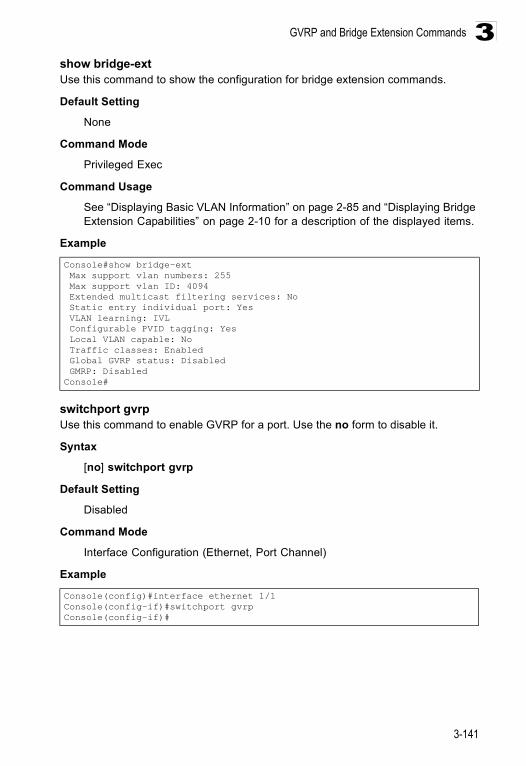
GVRP and Bridge Extension Commands
3-141
3show bridge-extUse this command to show the configuration for bridge extension commands.
Default Setting
None
Command Mode
Privileged Exec
Command Usage
See “Displaying Basic VLAN Information” on page 2-85 and “Displaying Bridge Extension Capabilities” on page 2-10 for a description of the displayed items.
Example
switchport gvrpUse this command to enable GVRP for a port. Use the no form to disable it.
Syntax
[no] switchport gvrp
Default Setting
Disabled
Command Mode
Interface Configuration (Ethernet, Port Channel)
Example
Console#show bridge-ext Max support vlan numbers: 255 Max support vlan ID: 4094 Extended multicast filtering services: No Static entry individual port: Yes VLAN learning: IVL Configurable PVID tagging: Yes Local VLAN capable: No Traffic classes: Enabled Global GVRP status: Disabled GMRP: DisabledConsole#
Console(config)#interface ethernet 1/1Console(config-if)#switchport gvrpConsole(config-if)#
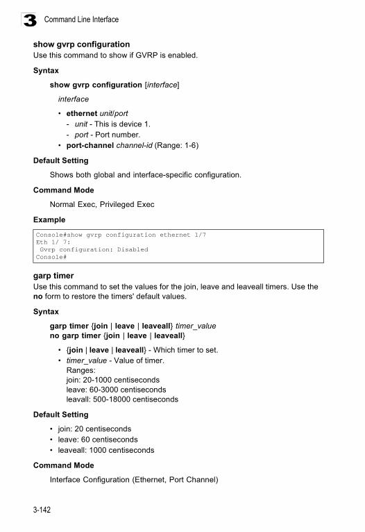
Command Line Interface
3-142
3show gvrp configurationUse this command to show if GVRP is enabled.
Syntax
show gvrp configuration [interface]
interface
• ethernet unit/port - unit - This is device 1. - port - Port number.
• port-channel channel-id (Range: 1-6)
Default Setting
Shows both global and interface-specific configuration.
Command Mode
Normal Exec, Privileged Exec
Example
garp timerUse this command to set the values for the join, leave and leaveall timers. Use the no form to restore the timers' default values.
Syntax
garp timer {join | leave | leaveall} timer_valueno garp timer {join | leave | leaveall}
• {join | leave | leaveall} - Which timer to set. • timer_value - Value of timer.
Ranges:join: 20-1000 centiseconds leave: 60-3000 centiseconds leavall: 500-18000 centiseconds
Default Setting
• join: 20 centiseconds• leave: 60 centiseconds• leaveall: 1000 centiseconds
Command Mode
Interface Configuration (Ethernet, Port Channel)
Console#show gvrp configuration ethernet 1/7Eth 1/ 7: Gvrp configuration: DisabledConsole#
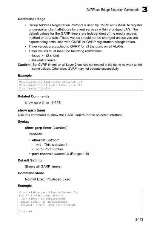
GVRP and Bridge Extension Commands
3-143
3Command Usage
• Group Address Registration Protocol is used by GVRP and GMRP to register or deregister client attributes for client services within a bridged LAN. The default values for the GARP timers are independent of the media access method or data rate. These values should not be changed unless you are experiencing difficulties with GMRP or GVRP registration/deregistration.
• Timer values are applied to GVRP for all the ports on all VLANs. • Timer values must meet the following restrictions:
- leave >= (2 x join) - leaveall > leave
Caution: Set GVRP timers on all Layer 2 devices connected in the same network to the same values. Otherwise, GVRP may not operate successfully.
Example
Related Commands
show garp timer (3-143)
show garp timerUse this command to show the GARP timers for the selected interface.
Syntax
show garp timer [interface]
interface
• ethernet unit/port - unit - This is device 1. - port - Port number.
• port-channel channel-id (Range: 1-6)
Default Setting
Shows all GARP timers.
Command Mode
Normal Exec, Privileged Exec
Example
Console(config)#interface ethernet 1/1Console(config-if)#garp timer join 100Console(config-if)#
Console#show garp timer ethernet 1/1Eth 1/ 1 GARP timer status: Join timer: 20 centiseconds Leave timer: 60 centiseconds Leaveall timer: 1000 centiseconds
Console#
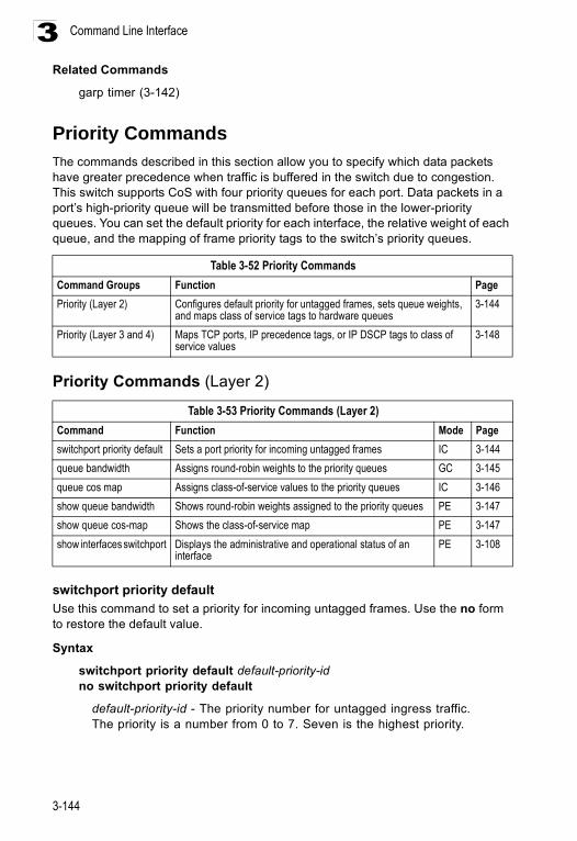
Command Line Interface
3-144
3Related Commands
garp timer (3-142)
Priority CommandsThe commands described in this section allow you to specify which data packets have greater precedence when traffic is buffered in the switch due to congestion. This switch supports CoS with four priority queues for each port. Data packets in a port’s high-priority queue will be transmitted before those in the lower-priority queues. You can set the default priority for each interface, the relative weight of each queue, and the mapping of frame priority tags to the switch’s priority queues.
Priority Commands (Layer 2)
switchport priority default Use this command to set a priority for incoming untagged frames. Use the no form to restore the default value.
Syntax
switchport priority default default-priority-idno switchport priority default
default-priority-id - The priority number for untagged ingress traffic. The priority is a number from 0 to 7. Seven is the highest priority.
Table 3-52 Priority CommandsCommand Groups Function PagePriority (Layer 2) Configures default priority for untagged frames, sets queue weights,
and maps class of service tags to hardware queues3-144
Priority (Layer 3 and 4) Maps TCP ports, IP precedence tags, or IP DSCP tags to class of service values
3-148
Table 3-53 Priority Commands (Layer 2)Command Function Mode Pageswitchport priority default Sets a port priority for incoming untagged frames IC 3-144queue bandwidth Assigns round-robin weights to the priority queues GC 3-145queue cos map Assigns class-of-service values to the priority queues IC 3-146show queue bandwidth Shows round-robin weights assigned to the priority queues PE 3-147show queue cos-map Shows the class-of-service map PE 3-147show interfaces switchport Displays the administrative and operational status of an
interfacePE 3-108
Priority Commands
3-145
3Default Setting
The priority is not set, and the default value for untagged frames received on the interface is zero.
Command Mode
Interface Configuration (Ethernet, Port Channel)
Command Usage
• The precedence for priority mapping is IP Port, IP Precedence or IP DSCP, and default switchport priority.
• The default priority applies for an untagged frame received on a port set to accept all frame types (i.e, receives both untagged and tagged frames). This priority does not apply to IEEE 802.1Q VLAN tagged frames. If the incoming frame is an IEEE 802.1Q VLAN tagged frame, the IEEE 802.1p User Priority bits will be used.
• This switch provides four priority queues for each port. It is configured to use Weighted Round Robin, which can be viewed with the show queue bandwidth command. Inbound frames that do not have VLAN tags are tagged with the input port’s default ingress user priority, and then placed in the appropriate priority queue at the output port. The default priority for all ingress ports is zero. Therefore, any inbound frames that do not have priority tags will be placed in queue 0 of the output port. (Note that if the output port is an untagged member of the associated VLAN, these frames are stripped of all VLAN tags prior to transmission.)
Example
The following example shows how to set a default priority on port 3 to 5:
queue bandwidth Use this command to assign weighted round-robin (WRR) weights to the four class of service (CoS) priority queues. Use the no form to restore the default weights.
Syntax
queue bandwidth weight1...weight4no queue bandwidth
weight1...weight4 - The ratio of weights for queues 0 - 3 determines the weights used by the WRR scheduler. (Range: 1 - 255)
Default Setting
Weights 1, 4, 16 and 64 are assigned to queue 0, 1, 2 and 3 respectively.
Command Mode
Global Configuration
Console(config)#interface ethernet 1/3Console (config-if)#switchport priority default 5
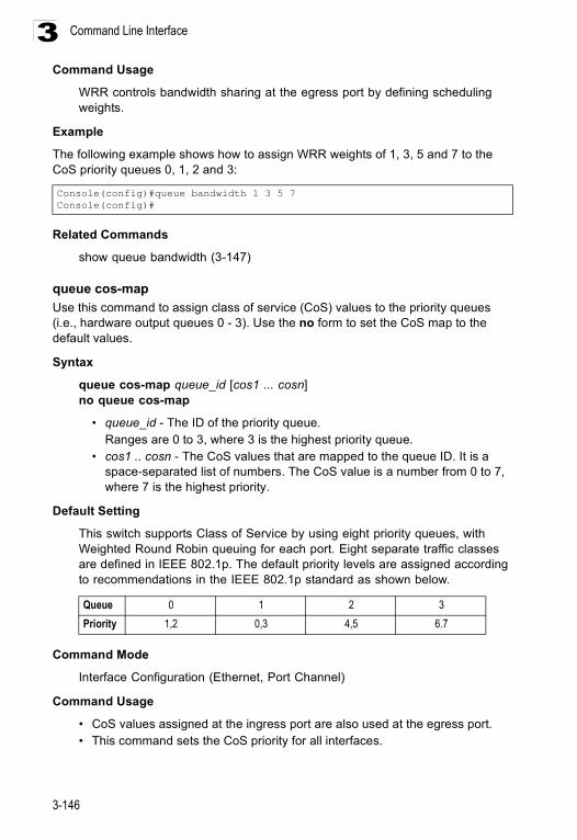
Command Line Interface
3-146
3Command Usage
WRR controls bandwidth sharing at the egress port by defining scheduling weights.
Example
The following example shows how to assign WRR weights of 1, 3, 5 and 7 to the CoS priority queues 0, 1, 2 and 3:
Related Commands
show queue bandwidth (3-147)
queue cos-mapUse this command to assign class of service (CoS) values to the priority queues (i.e., hardware output queues 0 - 3). Use the no form to set the CoS map to the default values.
Syntax
queue cos-map queue_id [cos1 ... cosn]no queue cos-map
• queue_id - The ID of the priority queue.Ranges are 0 to 3, where 3 is the highest priority queue.
• cos1 .. cosn - The CoS values that are mapped to the queue ID. It is a space-separated list of numbers. The CoS value is a number from 0 to 7, where 7 is the highest priority.
Default Setting
This switch supports Class of Service by using eight priority queues, with Weighted Round Robin queuing for each port. Eight separate traffic classes are defined in IEEE 802.1p. The default priority levels are assigned according to recommendations in the IEEE 802.1p standard as shown below.
Command Mode
Interface Configuration (Ethernet, Port Channel)
Command Usage
• CoS values assigned at the ingress port are also used at the egress port.• This command sets the CoS priority for all interfaces.
Console(config)#queue bandwidth 1 3 5 7Console(config)#
Queue 0 1 2 3Priority 1,2 0,3 4,5 6.7
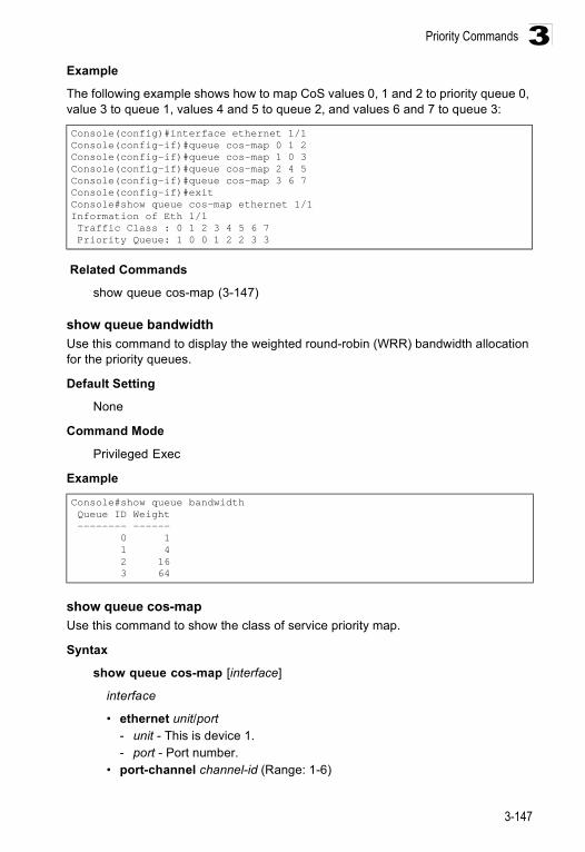
Priority Commands
3-147
3Example
The following example shows how to map CoS values 0, 1 and 2 to priority queue 0, value 3 to queue 1, values 4 and 5 to queue 2, and values 6 and 7 to queue 3:
Related Commands
show queue cos-map (3-147)
show queue bandwidthUse this command to display the weighted round-robin (WRR) bandwidth allocation for the priority queues.
Default Setting
None
Command Mode
Privileged Exec
Example
show queue cos-mapUse this command to show the class of service priority map.
Syntax
show queue cos-map [interface]
interface
• ethernet unit/port - unit - This is device 1. - port - Port number.
• port-channel channel-id (Range: 1-6)
Console(config)#interface ethernet 1/1Console(config-if)#queue cos-map 0 1 2Console(config-if)#queue cos-map 1 0 3Console(config-if)#queue cos-map 2 4 5Console(config-if)#queue cos-map 3 6 7Console(config-if)#exitConsole#show queue cos-map ethernet 1/1Information of Eth 1/1 Traffic Class : 0 1 2 3 4 5 6 7 Priority Queue: 1 0 0 1 2 2 3 3
Console#show queue bandwidth Queue ID Weight -------- ------ 0 1 1 4 2 16 3 64
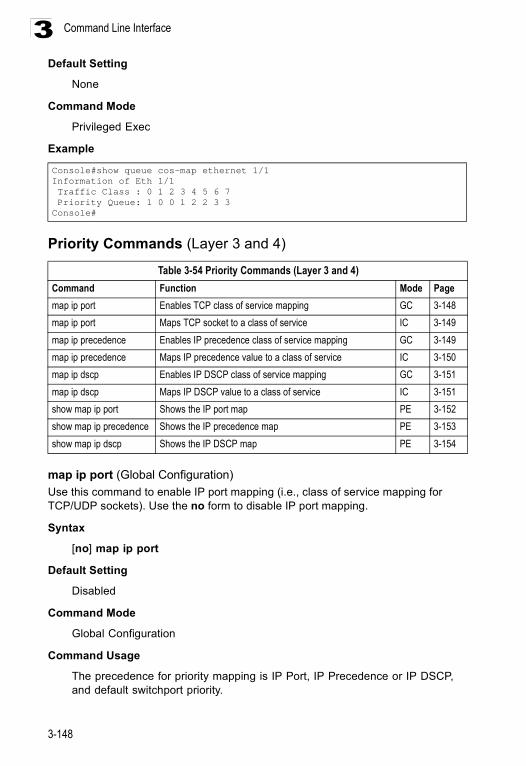
Command Line Interface
3-148
3Default Setting
None
Command Mode
Privileged Exec
Example
Priority Commands (Layer 3 and 4)
map ip port (Global Configuration)Use this command to enable IP port mapping (i.e., class of service mapping for TCP/UDP sockets). Use the no form to disable IP port mapping.
Syntax
[no] map ip port
Default Setting
Disabled
Command Mode
Global Configuration
Command Usage
The precedence for priority mapping is IP Port, IP Precedence or IP DSCP, and default switchport priority.
Console#show queue cos-map ethernet 1/1Information of Eth 1/1 Traffic Class : 0 1 2 3 4 5 6 7 Priority Queue: 1 0 0 1 2 2 3 3Console#
Table 3-54 Priority Commands (Layer 3 and 4)Command Function Mode Pagemap ip port Enables TCP class of service mapping GC 3-148map ip port Maps TCP socket to a class of service IC 3-149map ip precedence Enables IP precedence class of service mapping GC 3-149map ip precedence Maps IP precedence value to a class of service IC 3-150map ip dscp Enables IP DSCP class of service mapping GC 3-151map ip dscp Maps IP DSCP value to a class of service IC 3-151show map ip port Shows the IP port map PE 3-152show map ip precedence Shows the IP precedence map PE 3-153show map ip dscp Shows the IP DSCP map PE 3-154
Priority Commands
3-149
3Example
The following example shows how to enable TCP/UDP port mapping globally:
map ip port (Interface Configuration)Use this command to set IP port priority (i.e., TCP/UDP port priority). Use the no form to remove a specific setting.
Syntax
map ip port port-number cos cos-valueno map ip port port-number
• port-number - 16-bit TCP/UDP port number. (Range: 0-65535) • cos-value - Class-of-Service value (Range: 0-7)
Default Setting
None
Command Mode
Interface Configuration (Ethernet, Port Channel)
Command Usage
• The precedence for priority mapping is IP Port, IP Precedence or IP DSCP, and default switchport priority.
• This command sets the IP port priority for all interfaces.
Example
The following example shows how to map HTTP traffic to CoS value 0:
map ip precedence (Global Configuration) Use this command to enable IP precedence mapping (i.e., IP Type of Service). Use the no form to disable IP precedence mapping.
Syntax
[no] map ip precedence
Default Setting
Disabled
Command Mode
Global Configuration
Console(config)#map ip portConsole(config)#
Console(config)#interface ethernet 1/5Console(config-if)#map ip port 80 cos 0Console(config-if)#
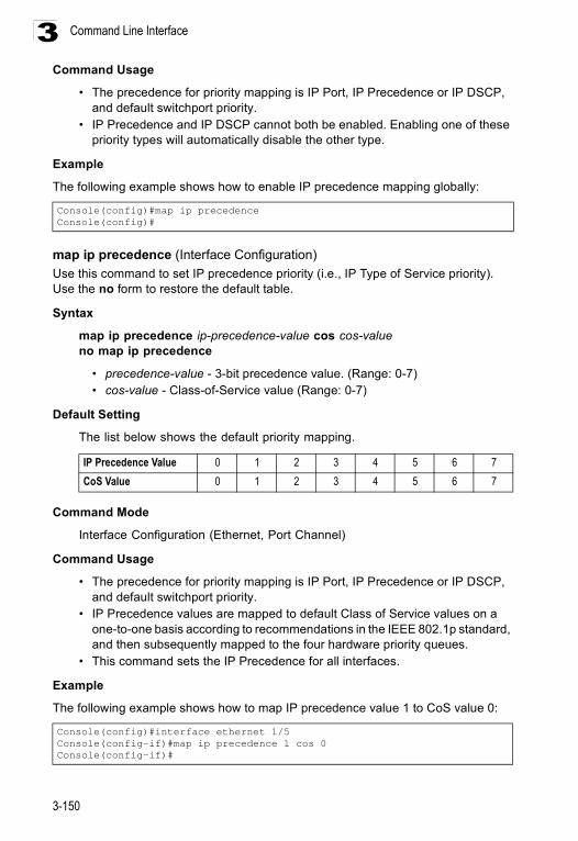
Command Line Interface
3-150
3Command Usage
• The precedence for priority mapping is IP Port, IP Precedence or IP DSCP, and default switchport priority.
• IP Precedence and IP DSCP cannot both be enabled. Enabling one of these priority types will automatically disable the other type.
Example
The following example shows how to enable IP precedence mapping globally:
map ip precedence (Interface Configuration)Use this command to set IP precedence priority (i.e., IP Type of Service priority). Use the no form to restore the default table.
Syntax
map ip precedence ip-precedence-value cos cos-valueno map ip precedence
• precedence-value - 3-bit precedence value. (Range: 0-7) • cos-value - Class-of-Service value (Range: 0-7)
Default Setting
The list below shows the default priority mapping.
Command Mode
Interface Configuration (Ethernet, Port Channel)
Command Usage
• The precedence for priority mapping is IP Port, IP Precedence or IP DSCP, and default switchport priority.
• IP Precedence values are mapped to default Class of Service values on a one-to-one basis according to recommendations in the IEEE 802.1p standard, and then subsequently mapped to the four hardware priority queues.
• This command sets the IP Precedence for all interfaces.
Example
The following example shows how to map IP precedence value 1 to CoS value 0:
Console(config)#map ip precedenceConsole(config)#
IP Precedence Value 0 1 2 3 4 5 6 7CoS Value 0 1 2 3 4 5 6 7
Console(config)#interface ethernet 1/5Console(config-if)#map ip precedence 1 cos 0Console(config-if)#
Priority Commands
3-151
3map ip dscp (Global Configuration)Use this command to enable IP DSCP mapping (i.e., Differentiated Services Code Point mapping). Use the no form to disable IP DSCP mapping.
Syntax
[no] map ip dscp
Default Setting
Disabled
Command Mode
Global Configuration
Command Usage
• The precedence for priority mapping is IP Port, IP Precedence or IP DSCP, and default switchport priority.
• IP Precedence and IP DSCP cannot both be enabled. Enabling one of these priority types will automatically disable the other type.
Example
The following example shows how to enable IP DSCP mapping globally:
map ip dscp (Interface Configuration)Use this command to set IP DSCP priority (i.e., Differentiated Services Code Point priority). Use the no form to restore the default table.
Syntax
map ip dscp dscp-value cos cos-valueno map ip dscp
• dscp-value - 8-bit DSCP value. (Range: 0-255) • cos-value - Class-of-Service value (Range: 0-7)
Console(config)#map ip dscpConsole(config)#
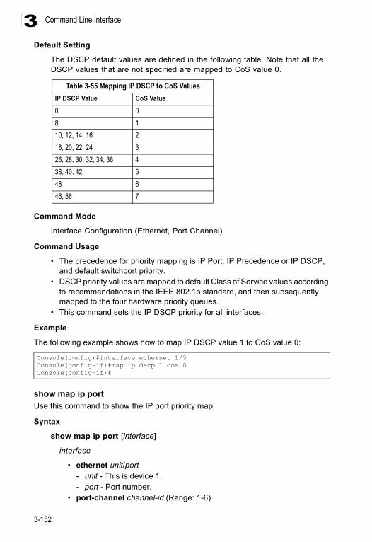
Command Line Interface
3-152
3Default Setting
The DSCP default values are defined in the following table. Note that all the DSCP values that are not specified are mapped to CoS value 0.
Command Mode
Interface Configuration (Ethernet, Port Channel)
Command Usage
• The precedence for priority mapping is IP Port, IP Precedence or IP DSCP, and default switchport priority.
• DSCP priority values are mapped to default Class of Service values according to recommendations in the IEEE 802.1p standard, and then subsequently mapped to the four hardware priority queues.
• This command sets the IP DSCP priority for all interfaces.
Example
The following example shows how to map IP DSCP value 1 to CoS value 0:
show map ip portUse this command to show the IP port priority map.
Syntax
show map ip port [interface]
interface
• ethernet unit/port - unit - This is device 1. - port - Port number.
• port-channel channel-id (Range: 1-6)
Table 3-55 Mapping IP DSCP to CoS ValuesIP DSCP Value CoS Value0 08 110, 12, 14, 16 218, 20, 22, 24 326, 28, 30, 32, 34, 36 438, 40, 42 548 646, 56 7
Console(config)#interface ethernet 1/5Console(config-if)#map ip dscp 1 cos 0Console(config-if)#
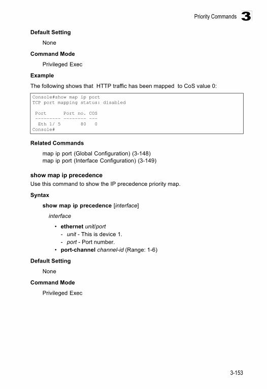
Priority Commands
3-153
3Default Setting
None
Command Mode
Privileged Exec
Example
The following shows that HTTP traffic has been mapped to CoS value 0:
Related Commands
map ip port (Global Configuration) (3-148)map ip port (Interface Configuration) (3-149)
show map ip precedenceUse this command to show the IP precedence priority map.
Syntax
show map ip precedence [interface]
interface
• ethernet unit/port - unit - This is device 1. - port - Port number.
• port-channel channel-id (Range: 1-6)
Default Setting
None
Command Mode
Privileged Exec
Console#show map ip portTCP port mapping status: disabled
Port Port no. COS --------- -------- --- Eth 1/ 5 80 0Console#
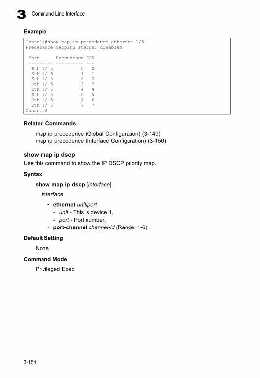
Command Line Interface
3-154
3Example
Related Commands
map ip precedence (Global Configuration) (3-149)map ip precedence (Interface Configuration) (3-150)
show map ip dscpUse this command to show the IP DSCP priority map.
Syntax
show map ip dscp [interface]
interface
• ethernet unit/port - unit - This is device 1. - port - Port number.
• port-channel channel-id (Range: 1-6)
Default Setting
None
Command Mode
Privileged Exec
Console#show map ip precedence ethernet 1/5Precedence mapping status: disabled
Port Precedence COS --------- ---------- --- Eth 1/ 5 0 0 Eth 1/ 5 1 1 Eth 1/ 5 2 2 Eth 1/ 5 3 3 Eth 1/ 5 4 4 Eth 1/ 5 5 5 Eth 1/ 5 6 6 Eth 1/ 5 7 7Console#
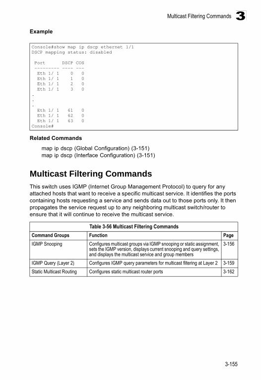
Multicast Filtering Commands
3-155
3Example
Related Commands
map ip dscp (Global Configuration) (3-151)map ip dscp (Interface Configuration) (3-151)
Multicast Filtering Commands This switch uses IGMP (Internet Group Management Protocol) to query for any attached hosts that want to receive a specific multicast service. It identifies the ports containing hosts requesting a service and sends data out to those ports only. It then propagates the service request up to any neighboring multicast switch/router to ensure that it will continue to receive the multicast service.
Console#show map ip dscp ethernet 1/1DSCP mapping status: disabled
Port DSCP COS --------- ---- --- Eth 1/ 1 0 0 Eth 1/ 1 1 0 Eth 1/ 1 2 0 Eth 1/ 1 3 0... Eth 1/ 1 61 0 Eth 1/ 1 62 0 Eth 1/ 1 63 0Console#
Table 3-56 Multicast Filtering CommandsCommand Groups Function PageIGMP Snooping Configures multicast groups via IGMP snooping or static assignment,
sets the IGMP version, displays current snooping and query settings, and displays the multicast service and group members
3-156
IGMP Query (Layer 2) Configures IGMP query parameters for multicast filtering at Layer 2 3-159Static Multicast Routing Configures static multicast router ports 3-162
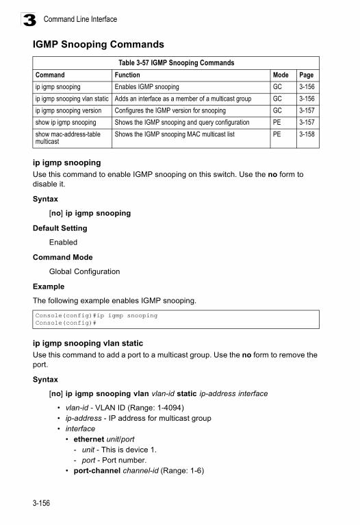
Command Line Interface
3-156
3IGMP Snooping Commands
ip igmp snoopingUse this command to enable IGMP snooping on this switch. Use the no form to disable it.
Syntax
[no] ip igmp snooping
Default Setting
Enabled
Command Mode
Global Configuration
Example
The following example enables IGMP snooping.
ip igmp snooping vlan staticUse this command to add a port to a multicast group. Use the no form to remove the port.
Syntax
[no] ip igmp snooping vlan vlan-id static ip-address interface
• vlan-id - VLAN ID (Range: 1-4094) • ip-address - IP address for multicast group • interface
• ethernet unit/port - unit - This is device 1. - port - Port number.
• port-channel channel-id (Range: 1-6)
Table 3-57 IGMP Snooping CommandsCommand Function Mode Pageip igmp snooping Enables IGMP snooping GC 3-156ip igmp snooping vlan static Adds an interface as a member of a multicast group GC 3-156ip igmp snooping version Configures the IGMP version for snooping GC 3-157show ip igmp snooping Shows the IGMP snooping and query configuration PE 3-157show mac-address-table multicast
Shows the IGMP snooping MAC multicast list PE 3-158
Console(config)#ip igmp snoopingConsole(config)#
Multicast Filtering Commands
3-157
3Default Setting
None
Command Mode
Global Configuration
Example
The following shows how to statically configure a multicast group on a port:
ip igmp snooping versionUse this command to configure the IGMP snooping version. Use the no form to restore the default.
Syntax
ip igmp snooping version {1 | 2}no ip igmp snooping version
• 1 - IGMP Version 1 • 2 - IGMP Version 2
Default Setting
IGMP Version 2
Command Mode
Global Configuration
Command Usage
• All systems on the subnet must support the same version. If there are legacy devices in your network that only support Version 1, you will also have to configure this switch to use Version 1.
• Some commands are only enabled for IGMPv2, including ip igmp query-max-response-time and ip igmp query-timeout.
Example
The following configures the switch to use IGMP Version 1:
show ip igmp snoopingUse this command to show the IGMP snooping configuration.
Default Setting
None
Console(config)#ip igmp snooping vlan 1 static 224.0.0.12 ethernet 1/5Console(config)#
Console(config)#ip igmp snooping version 1Console(config)#
Command Line Interface
3-158
3Command Mode
Privileged Exec
Command Usage
See “Configuring IGMP Snooping Parameters” on page 2-74 for a description of the displayed items.
Example
The following shows the current IGMP snooping configuration:
show mac-address-table multicastUse this command to show known multicast addresses.
Syntax
show mac-address-table multicast [vlan vlan-id] [user | igmp-snooping]
• vlan-id - VLAN ID (1 to 4094) • user - Display only the user-configured multicast entries. • igmp-snooping - Display only entries learned through IGMP snooping.
Default Setting
None
Command Mode
Privileged Exec
Command Usage
Member types displayed include IGMP or USER, depending on selected options.
Example
The following shows the multicast entries learned through IGMP snooping for VLAN 1:
Console#show ip igmp snooping Service status: Enabled Querier status: Enabled Query count: 2 Query interval: 125 sec Query max response time: 10 sec Query time-out: 300 sec IGMP snooping version: Version 2Console#
Console#show mac-address-table multicast vlan 1 igmp-snooping VLAN M'cast IP addr. Member ports Type ---- --------------- ------------ ------- 1 224.1.2.3 Eth1/11 IGMPConsole#
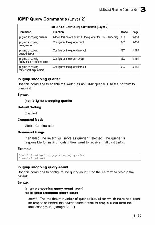
Multicast Filtering Commands
3-159
3IGMP Query Commands (Layer 2)
ip igmp snooping querierUse this command to enable the switch as an IGMP querier. Use the no form to disable it.
Syntax
[no] ip igmp snooping querier
Default Setting
Enabled
Command Mode
Global Configuration
Command Usage
If enabled, the switch will serve as querier if elected. The querier is responsible for asking hosts if they want to receive multicast traffic.
Example
ip igmp snooping query-countUse this command to configure the query count. Use the no form to restore the default.
Syntax
ip igmp snooping query-count countno ip igmp snooping query-count
count - The maximum number of queries issued for which there has been no response before the switch takes action to drop a client from the multicast group. (Range: 2-10)
Table 3-58 IGMP Query Commands (Layer 2)Command Function Mode Pageip igmp snooping querier Allows this device to act as the querier for IGMP snooping GC 3-159ip igmp snooping query-count
Configures the query count GC 3-159
ip igmp snooping query-interval
Configures the query interval GC 3-160
ip igmp snooping query-max-response-time
Configures the report delay GC 3-161
ip igmp snooping router-port-expire-time
Configures the query timeout GC 3-161
Console(config)#ip igmp snooping querierConsole(config)#
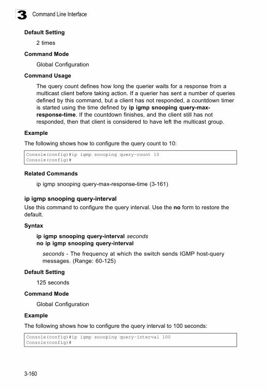
Command Line Interface
3-160
3Default Setting
2 times
Command Mode
Global Configuration
Command Usage
The query count defines how long the querier waits for a response from a multicast client before taking action. If a querier has sent a number of queries defined by this command, but a client has not responded, a countdown timer is started using the time defined by ip igmp snooping query-max- response-time. If the countdown finishes, and the client still has not responded, then that client is considered to have left the multicast group.
Example
The following shows how to configure the query count to 10:
Related Commands
ip igmp snooping query-max-response-time (3-161)
ip igmp snooping query-intervalUse this command to configure the query interval. Use the no form to restore the default.
Syntax
ip igmp snooping query-interval secondsno ip igmp snooping query-interval
seconds - The frequency at which the switch sends IGMP host-query messages. (Range: 60-125)
Default Setting
125 seconds
Command Mode
Global Configuration
Example
The following shows how to configure the query interval to 100 seconds:
Console(config)#ip igmp snooping query-count 10Console(config)#
Console(config)#ip igmp snooping query-interval 100Console(config)#
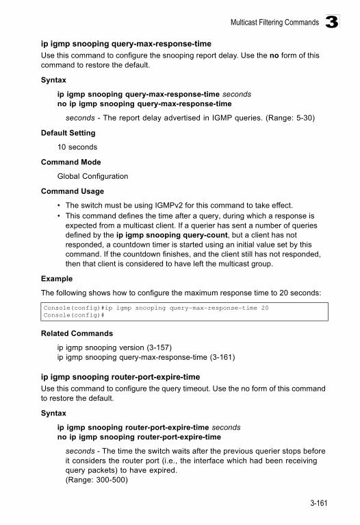
Multicast Filtering Commands
3-161
3ip igmp snooping query-max-response-timeUse this command to configure the snooping report delay. Use the no form of this command to restore the default.
Syntax
ip igmp snooping query-max-response-time secondsno ip igmp snooping query-max-response-time
seconds - The report delay advertised in IGMP queries. (Range: 5-30)
Default Setting
10 seconds
Command Mode
Global Configuration
Command Usage
• The switch must be using IGMPv2 for this command to take effect. • This command defines the time after a query, during which a response is
expected from a multicast client. If a querier has sent a number of queries defined by the ip igmp snooping query-count, but a client has not responded, a countdown timer is started using an initial value set by this command. If the countdown finishes, and the client still has not responded, then that client is considered to have left the multicast group.
Example
The following shows how to configure the maximum response time to 20 seconds:
Related Commands
ip igmp snooping version (3-157)ip igmp snooping query-max-response-time (3-161)
ip igmp snooping router-port-expire-timeUse this command to configure the query timeout. Use the no form of this command to restore the default.
Syntax
ip igmp snooping router-port-expire-time secondsno ip igmp snooping router-port-expire-time
seconds - The time the switch waits after the previous querier stops before it considers the router port (i.e., the interface which had been receiving query packets) to have expired. (Range: 300-500)
Console(config)#ip igmp snooping query-max-response-time 20Console(config)#
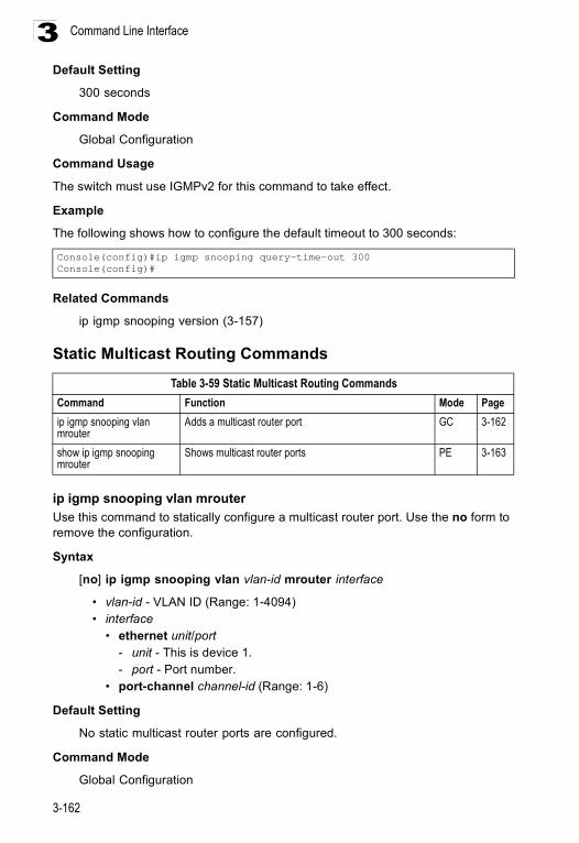
Command Line Interface
3-162
3Default Setting
300 seconds
Command Mode
Global Configuration
Command Usage
The switch must use IGMPv2 for this command to take effect.
Example
The following shows how to configure the default timeout to 300 seconds:
Related Commands
ip igmp snooping version (3-157)
Static Multicast Routing Commands
ip igmp snooping vlan mrouterUse this command to statically configure a multicast router port. Use the no form to remove the configuration.
Syntax
[no] ip igmp snooping vlan vlan-id mrouter interface
• vlan-id - VLAN ID (Range: 1-4094) • interface
• ethernet unit/port - unit - This is device 1. - port - Port number.
• port-channel channel-id (Range: 1-6)
Default Setting
No static multicast router ports are configured.
Command Mode
Global Configuration
Console(config)#ip igmp snooping query-time-out 300Console(config)#
Table 3-59 Static Multicast Routing CommandsCommand Function Mode Pageip igmp snooping vlan mrouter
Adds a multicast router port GC 3-162
show ip igmp snooping mrouter
Shows multicast router ports PE 3-163
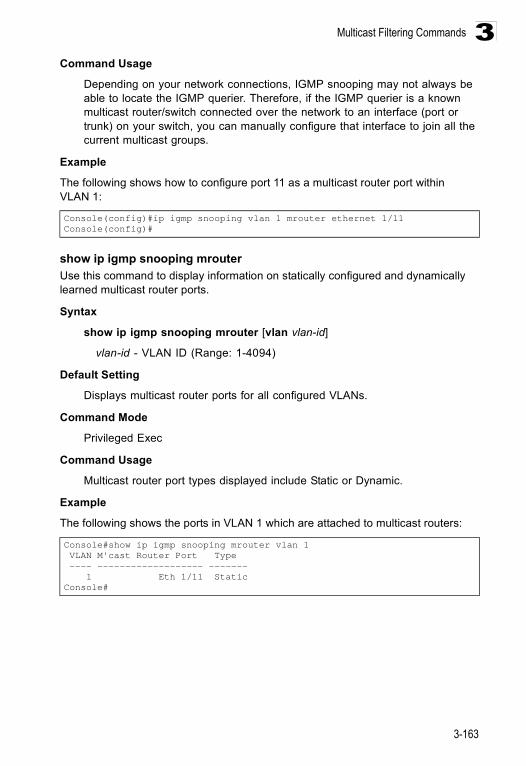
Multicast Filtering Commands
3-163
3Command Usage
Depending on your network connections, IGMP snooping may not always be able to locate the IGMP querier. Therefore, if the IGMP querier is a known multicast router/switch connected over the network to an interface (port or trunk) on your switch, you can manually configure that interface to join all the current multicast groups.
Example
The following shows how to configure port 11 as a multicast router port within VLAN 1:
show ip igmp snooping mrouter Use this command to display information on statically configured and dynamically learned multicast router ports.
Syntax
show ip igmp snooping mrouter [vlan vlan-id]
vlan-id - VLAN ID (Range: 1-4094)
Default Setting
Displays multicast router ports for all configured VLANs.
Command Mode
Privileged Exec
Command Usage
Multicast router port types displayed include Static or Dynamic.
Example
The following shows the ports in VLAN 1 which are attached to multicast routers:
Console(config)#ip igmp snooping vlan 1 mrouter ethernet 1/11Console(config)#
Console#show ip igmp snooping mrouter vlan 1 VLAN M'cast Router Port Type ---- ------------------- ------- 1 Eth 1/11 StaticConsole#
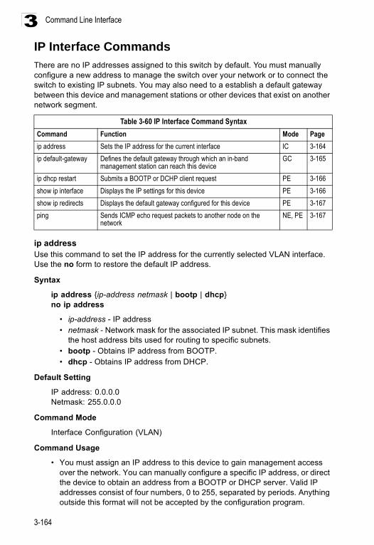
Command Line Interface
3-164
3IP Interface CommandsThere are no IP addresses assigned to this switch by default. You must manually configure a new address to manage the switch over your network or to connect the switch to existing IP subnets. You may also need to a establish a default gateway between this device and management stations or other devices that exist on another network segment.
ip address Use this command to set the IP address for the currently selected VLAN interface. Use the no form to restore the default IP address.
Syntax
ip address {ip-address netmask | bootp | dhcp}no ip address
• ip-address - IP address • netmask - Network mask for the associated IP subnet. This mask identifies
the host address bits used for routing to specific subnets. • bootp - Obtains IP address from BOOTP. • dhcp - Obtains IP address from DHCP.
Default Setting
IP address: 0.0.0.0Netmask: 255.0.0.0
Command Mode
Interface Configuration (VLAN)
Command Usage
• You must assign an IP address to this device to gain management access over the network. You can manually configure a specific IP address, or direct the device to obtain an address from a BOOTP or DHCP server. Valid IP addresses consist of four numbers, 0 to 255, separated by periods. Anything outside this format will not be accepted by the configuration program.
Table 3-60 IP Interface Command SyntaxCommand Function Mode Pageip address Sets the IP address for the current interface IC 3-164ip default-gateway Defines the default gateway through which an in-band
management station can reach this deviceGC 3-165
ip dhcp restart Submits a BOOTP or DCHP client request PE 3-166show ip interface Displays the IP settings for this device PE 3-166show ip redirects Displays the default gateway configured for this device PE 3-167ping Sends ICMP echo request packets to another node on the
network NE, PE 3-167
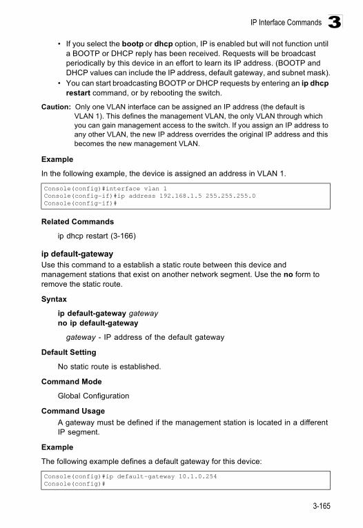
IP Interface Commands
3-165
3• If you select the bootp or dhcp option, IP is enabled but will not function until
a BOOTP or DHCP reply has been received. Requests will be broadcast periodically by this device in an effort to learn its IP address. (BOOTP and DHCP values can include the IP address, default gateway, and subnet mask).
• You can start broadcasting BOOTP or DHCP requests by entering an ip dhcp restart command, or by rebooting the switch.
Caution: Only one VLAN interface can be assigned an IP address (the default is VLAN 1). This defines the management VLAN, the only VLAN through which you can gain management access to the switch. If you assign an IP address to any other VLAN, the new IP address overrides the original IP address and this becomes the new management VLAN.
Example
In the following example, the device is assigned an address in VLAN 1.
Related Commands
ip dhcp restart (3-166)
ip default-gatewayUse this command to a establish a static route between this device and management stations that exist on another network segment. Use the no form to remove the static route.
Syntax
ip default-gateway gatewayno ip default-gateway
gateway - IP address of the default gateway
Default Setting
No static route is established.
Command Mode
Global Configuration
Command Usage A gateway must be defined if the management station is located in a different IP segment.
Example
The following example defines a default gateway for this device:
Console(config)#interface vlan 1Console(config-if)#ip address 192.168.1.5 255.255.255.0Console(config-if)#
Console(config)#ip default-gateway 10.1.0.254Console(config)#
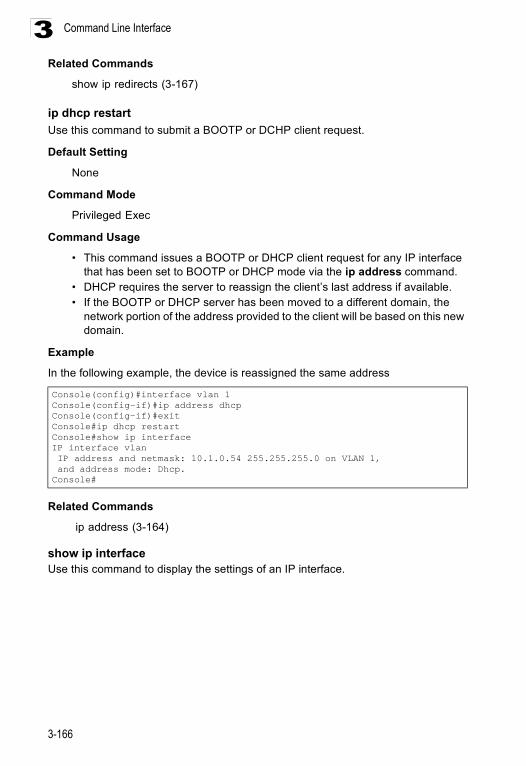
Command Line Interface
3-166
3Related Commands
show ip redirects (3-167)
ip dhcp restartUse this command to submit a BOOTP or DCHP client request.
Default Setting
None
Command Mode
Privileged Exec
Command Usage
• This command issues a BOOTP or DHCP client request for any IP interface that has been set to BOOTP or DHCP mode via the ip address command.
• DHCP requires the server to reassign the client’s last address if available. • If the BOOTP or DHCP server has been moved to a different domain, the
network portion of the address provided to the client will be based on this new domain.
Example
In the following example, the device is reassigned the same address
Related Commands
ip address (3-164)
show ip interfaceUse this command to display the settings of an IP interface.
Console(config)#interface vlan 1Console(config-if)#ip address dhcpConsole(config-if)#exitConsole#ip dhcp restartConsole#show ip interfaceIP interface vlan IP address and netmask: 10.1.0.54 255.255.255.0 on VLAN 1, and address mode: Dhcp.Console#
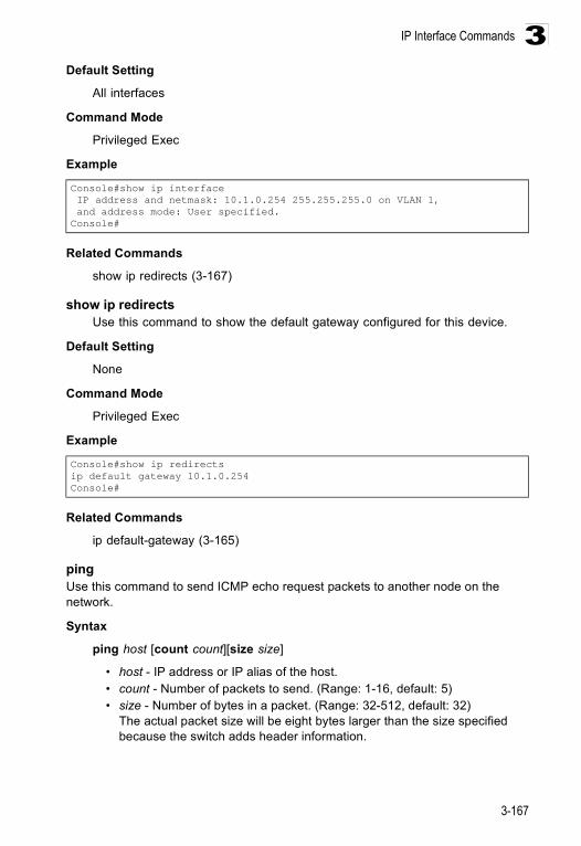
IP Interface Commands
3-167
3Default Setting
All interfaces
Command Mode
Privileged Exec
Example
Related Commands
show ip redirects (3-167)
show ip redirectsUse this command to show the default gateway configured for this device.
Default Setting
None
Command Mode
Privileged Exec
Example
Related Commands
ip default-gateway (3-165)
pingUse this command to send ICMP echo request packets to another node on the network.
Syntax
ping host [count count][size size]
• host - IP address or IP alias of the host. • count - Number of packets to send. (Range: 1-16, default: 5) • size - Number of bytes in a packet. (Range: 32-512, default: 32)
The actual packet size will be eight bytes larger than the size specified because the switch adds header information.
Console#show ip interface IP address and netmask: 10.1.0.254 255.255.255.0 on VLAN 1, and address mode: User specified.Console#
Console#show ip redirectsip default gateway 10.1.0.254Console#
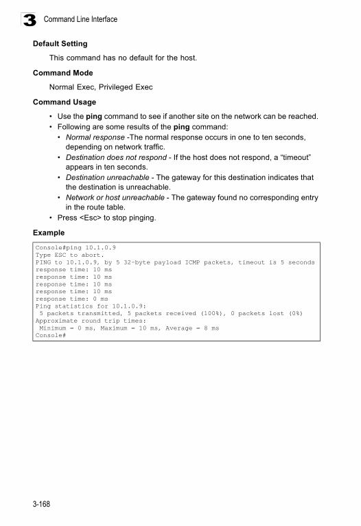
Command Line Interface
3-168
3Default Setting
This command has no default for the host.
Command Mode
Normal Exec, Privileged Exec
Command Usage
• Use the ping command to see if another site on the network can be reached. • Following are some results of the ping command:
• Normal response -The normal response occurs in one to ten seconds, depending on network traffic.
• Destination does not respond - If the host does not respond, a “timeout” appears in ten seconds.
• Destination unreachable - The gateway for this destination indicates that the destination is unreachable.
• Network or host unreachable - The gateway found no corresponding entry in the route table.
• Press <Esc> to stop pinging.
Example
Console#ping 10.1.0.9Type ESC to abort.PING to 10.1.0.9, by 5 32-byte payload ICMP packets, timeout is 5 secondsresponse time: 10 msresponse time: 10 msresponse time: 10 msresponse time: 10 msresponse time: 0 msPing statistics for 10.1.0.9: 5 packets transmitted, 5 packets received (100%), 0 packets lost (0%)Approximate round trip times: Minimum = 0 ms, Maximum = 10 ms, Average = 8 msConsole#
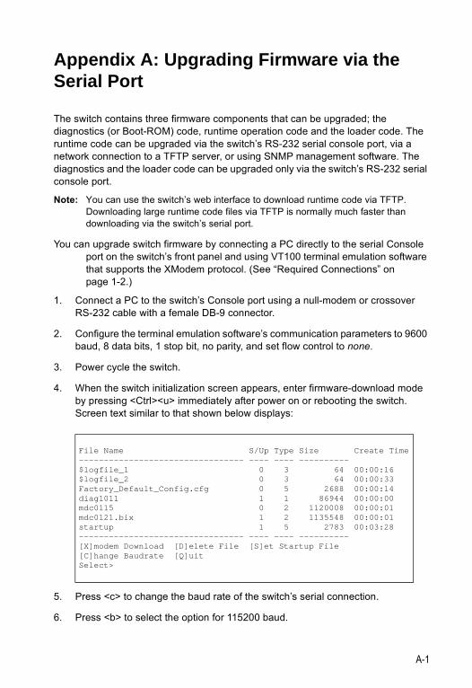
A-1
Appendix A: Upgrading Firmware via the Serial Port
The switch contains three firmware components that can be upgraded; the diagnostics (or Boot-ROM) code, runtime operation code and the loader code. The runtime code can be upgraded via the switch’s RS-232 serial console port, via a network connection to a TFTP server, or using SNMP management software. The diagnostics and the loader code can be upgraded only via the switch’s RS-232 serial console port.
Note: You can use the switch’s web interface to download runtime code via TFTP. Downloading large runtime code files via TFTP is normally much faster than downloading via the switch’s serial port.
You can upgrade switch firmware by connecting a PC directly to the serial Console port on the switch’s front panel and using VT100 terminal emulation software that supports the XModem protocol. (See “Required Connections” on page 1-2.)
1. Connect a PC to the switch’s Console port using a null-modem or crossover RS-232 cable with a female DB-9 connector.
2. Configure the terminal emulation software’s communication parameters to 9600 baud, 8 data bits, 1 stop bit, no parity, and set flow control to none.
3. Power cycle the switch.
4. When the switch initialization screen appears, enter firmware-download mode by pressing <Ctrl><u> immediately after power on or rebooting the switch. Screen text similar to that shown below displays:
5. Press <c> to change the baud rate of the switch’s serial connection.
6. Press <b> to select the option for 115200 baud.
File Name S/Up Type Size Create Time--------------------------------- ---- ---- ---------- $logfile_1 0 3 64 00:00:16$logfile_2 0 3 64 00:00:33Factory_Default_Config.cfg 0 5 2688 00:00:14diag1011 1 1 86944 00:00:00mdc0115 0 2 1120008 00:00:01mdc0121.bix 1 2 1135548 00:00:01startup 1 5 2783 00:03:28--------------------------------- ---- ---- ---------- [X]modem Download [D]elete File [S]et Startup File[C]hange Baudrate [Q]uitSelect>
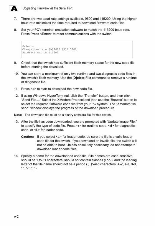
Upgrading Firmware via the Serial Port
A-2
A7. There are two baud rate settings available, 9600 and 115200. Using the higher
baud rate minimizes the time required to download firmware code files.
8. Set your PC’s terminal emulation software to match the 115200 baud rate. Press Press <Enter> to reset communications with the switch.
9. Check that the switch has sufficient flash memory space for the new code file before starting the download.
10. You can store a maximum of only two runtime and two diagnostic code files in the switch’s flash memory. Use the [D]elete File command to remove a runtime or diagnostic file.
11. Press <x> to start to download the new code file.
12. If using Windows HyperTerminal, click the “Transfer” button, and then click “Send File....” Select the XModem Protocol and then use the “Browse” button to select the required firmware code file from your PC system. The “Xmodem file send” window displays the progress of the download procedure.
Note: The download file must be a binary software file for this switch.
13. After the file has been downloaded, you are prompted with “Update Image File:” to specify the type of code file. Press <r> for runtime code, <d> for diagnostic code, or <L> for loader code.
Caution: If you select <L> for loader code, be sure the file is a valid loader code file for the switch. If you download an invalid file, the switch will not be able to boot. Unless absolutely necessary, do not attempt to download loader code files.
14. Specify a name for the downloaded code file. File names are case-sensitive, should be 1 to 31 characters, should not contain slashes (\ or /), and the leading letter of the file name should not be a period (.). (Valid characters: A-Z, a-z, 0-9, “.”, “-”, “_”)
Select>Change baudrate [A]9600 [B]115200Baudrate set to 115200
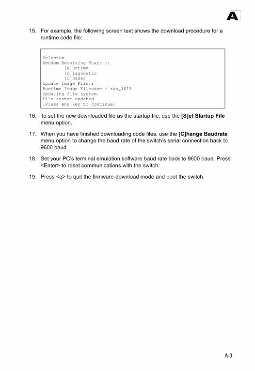
A-3
A15. For example, the following screen text shows the download procedure for a
runtime code file:
16. To set the new downloaded file as the startup file, use the [S]et Startup File menu option.
17. When you have finished downloading code files, use the [C]hange Baudrate menu option to change the baud rate of the switch’s serial connection back to 9600 baud.
18. Set your PC’s terminal emulation software baud rate back to 9600 baud. Press <Enter> to reset communications with the switch.
19. Press <q> to quit the firmware-download mode and boot the switch.
Select>xXmodem Receiving Start :: [R]untime [D]iagnostic [L]oaderUpdate Image File:rRuntime Image Filename : run_1013Updating file system.File system updated.[Press any key to continue]

Upgrading Firmware via the Serial Port
A-4
A
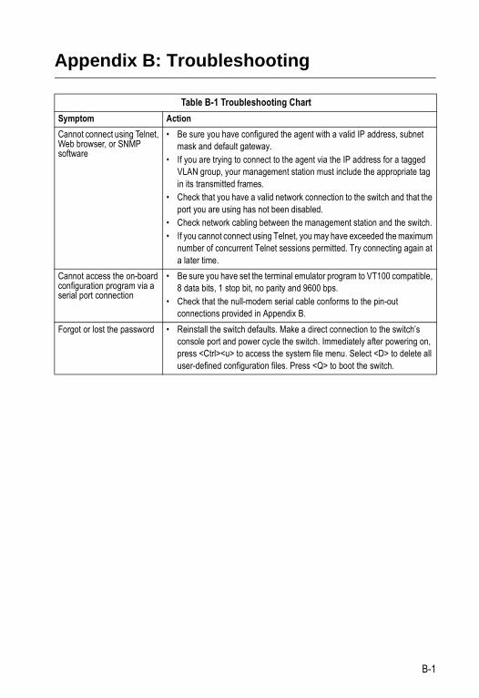
B-1
Appendix B: Troubleshooting
Table B-1 Troubleshooting ChartSymptom ActionCannot connect using Telnet, Web browser, or SNMP software
• Be sure you have configured the agent with a valid IP address, subnet mask and default gateway.
• If you are trying to connect to the agent via the IP address for a tagged VLAN group, your management station must include the appropriate tag in its transmitted frames.
• Check that you have a valid network connection to the switch and that the port you are using has not been disabled.
• Check network cabling between the management station and the switch.• If you cannot connect using Telnet, you may have exceeded the maximum
number of concurrent Telnet sessions permitted. Try connecting again at a later time.
Cannot access the on-board configuration program via a serial port connection
• Be sure you have set the terminal emulator program to VT100 compatible, 8 data bits, 1 stop bit, no parity and 9600 bps.
• Check that the null-modem serial cable conforms to the pin-out connections provided in Appendix B.
Forgot or lost the password • Reinstall the switch defaults. Make a direct connection to the switch’s console port and power cycle the switch. Immediately after powering on, press <Ctrl><u> to access the system file menu. Select <D> to delete all user-defined configuration files. Press <Q> to boot the switch.

Troubleshooting
B-2
B
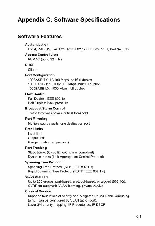
C-1
Appendix C: Software Specifications
Software FeaturesAuthentication
Local, RADIUS, TACACS, Port (802.1x), HTTPS, SSH, Port SecurityAccess Control Lists
IP, MAC (up to 32 lists)DHCP
ClientPort Configuration
100BASE-TX: 10/100 Mbps, half/full duplex1000BASE-T: 10/100/1000 Mbps, half/full duplex1000BASE-LX: 1000 Mbps, full duplex
Flow ControlFull Duplex: IEEE 802.3xHalf Duplex: Back pressure
Broadcast Storm Control Traffic throttled above a critical threshold
Port MirroringMultiple source ports, one destination port
Rate LimitsInput limitOutput limitRange (configured per port)
Port TrunkingStatic trunks (Cisco EtherChannel compliant)Dynamic trunks (Link Aggregation Control Protocol)
Spanning Tree ProtocolSpanning Tree Protocol (STP, IEEE 802.1D) Rapid Spanning Tree Protocol (RSTP, IEEE 802.1w)
VLAN SupportUp to 255 groups; port-based, protocol-based, or tagged (802.1Q),GVRP for automatic VLAN learning, private VLANs
Class of ServiceSupports four levels of priority and Weighted Round Robin Queueing(which can be configured by VLAN tag or port),Layer 3/4 priority mapping: IP Precedence, IP DSCP
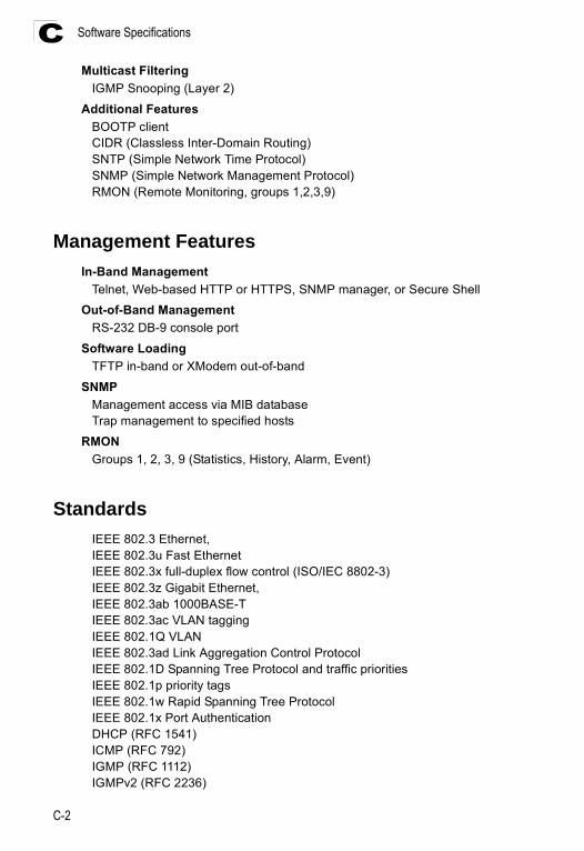
Software Specifications
C-2
CMulticast Filtering
IGMP Snooping (Layer 2)Additional Features
BOOTP clientCIDR (Classless Inter-Domain Routing)SNTP (Simple Network Time Protocol)SNMP (Simple Network Management Protocol)RMON (Remote Monitoring, groups 1,2,3,9)
Management FeaturesIn-Band Management
Telnet, Web-based HTTP or HTTPS, SNMP manager, or Secure ShellOut-of-Band Management
RS-232 DB-9 console portSoftware Loading
TFTP in-band or XModem out-of-bandSNMP
Management access via MIB databaseTrap management to specified hosts
RMONGroups 1, 2, 3, 9 (Statistics, History, Alarm, Event)
StandardsIEEE 802.3 Ethernet, IEEE 802.3u Fast EthernetIEEE 802.3x full-duplex flow control (ISO/IEC 8802-3)IEEE 802.3z Gigabit Ethernet, IEEE 802.3ab 1000BASE-TIEEE 802.3ac VLAN taggingIEEE 802.1Q VLANIEEE 802.3ad Link Aggregation Control ProtocolIEEE 802.1D Spanning Tree Protocol and traffic prioritiesIEEE 802.1p priority tagsIEEE 802.1w Rapid Spanning Tree ProtocolIEEE 802.1x Port AuthenticationDHCP (RFC 1541)ICMP (RFC 792)IGMP (RFC 1112)IGMPv2 (RFC 2236)
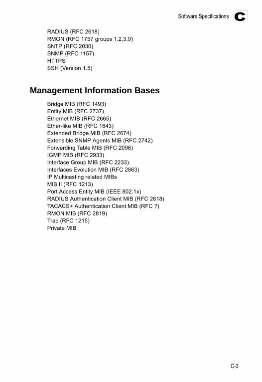
Software Specifications
C-3
CRADIUS (RFC 2618)RMON (RFC 1757 groups 1,2,3,9)SNTP (RFC 2030)SNMP (RFC 1157)HTTPSSSH (Version 1.5)
Management Information BasesBridge MIB (RFC 1493)Entity MIB (RFC 2737)Ethernet MIB (RFC 2665)Ether-like MIB (RFC 1643)Extended Bridge MIB (RFC 2674)Extensible SNMP Agents MIB (RFC 2742)Forwarding Table MIB (RFC 2096)IGMP MIB (RFC 2933)Interface Group MIB (RFC 2233)Interfaces Evolution MIB (RFC 2863)IP Multicasting related MIBs MIB II (RFC 1213)Port Access Entity MIB (IEEE 802.1x)RADIUS Authentication Client MIB (RFC 2618)TACACS+ Authentication Client MIB (RFC ?)RMON MIB (RFC 2819)Trap (RFC 1215)Private MIB

Software Specifications
C-4
C
Glossary-1
Glossary
Access Control List (ACL)ACLs can limit network traffic and restrict access to certain users or devices by checking each packet for certain IP or MAC (i.e., Layer 2) information.
Boot Protocol (BOOTP)BOOTP is used to provide bootup information for network devices, including IP address information, the address of the TFTP server that contains the devices system files, and the name of the boot file.
Class of Service (CoS)CoS is supported by prioritizing packets based on the required level of service, and then placing them in the appropriate output queue. Data is transmitted from the queues using weighted round-robin service to enforce priority service and prevent blockage of lower-level queues. Priority may be set according to the port default, the packet’s priority bit (in the VLAN tag), TCP/UDP port number, IP Precedence bit, or DSCP priority bit.
Differentiated Services Code Point Service (DSCP)DSCP uses a six-bit tag to provide for up to 64 different forwarding behaviors. Based on network policies, different kinds of traffic can be marked for different kinds of forwarding. The DSCP bits are mapped to the Class of Service categories, and then into the output queues.
Dynamic Host Control Protocol (DHCP)Provides a framework for passing configuration information to hosts on a TCP/IP network. DHCP is based on the Bootstrap Protocol (BOOTP), adding the capability of automatic allocation of reusable network addresses and additional configuration options.
Extensible Authentication Protocol over LAN (EAPOL) EAPOL is a client authentication protocol used by this switch to verify the network access rights for any device that is plugged into the switch. A user name and password is requested by the switch, and then passed to an authentication server (e.g., RADIUS) for verification. EAPOL is implemented as part of the IEEE 802.1x Port Authentication standard.
GARP VLAN Registration Protocol (GVRP)Defines a way for switches to exchange VLAN information in order to register necessary VLAN members on ports along the Spanning Tree so that VLANs defined in each switch can work automatically over a Spanning Tree network.
Glossary
Glossary-2
Generic Attribute Registration Protocol (GARP)GARP is a protocol that can be used by endstations and switches to register and propagate multicast group membership information in a switched environment so that multicast data frames are propagated only to those parts of a switched LAN containing registered endstations. Formerly called Group Address Registration Protocol.
Generic Multicast Registration Protocol (GMRP)GMRP allows network devices to register end stations with multicast groups. GMRP requires that any participating network devices or end stations comply with the IEEE 802.1p standard.
Group Attribute Registration Protocol (GARP)See Generic Attribute Registration Protocol.
IEEE 802.1DSpecifies a general method for the operation of MAC bridges, including the Spanning Tree Protocol.
IEEE 802.1QVLAN Tagging—Defines Ethernet frame tags which carry VLAN information. It allows switches to assign endstations to different virtual LANs, and defines a standard way for VLANs to communicate across switched networks.
IEEE 802.1pAn IEEE standard for providing quality of service (QoS) in Ethernet networks. The standard uses packet tags that define up to eight traffic classes and allows switches to transmit packets based on the tagged priority value.
IEEE 802.1xPort Authentication controls access to the switch ports by requiring users to first enter a user ID and password for authentication.
IEEE 802.3acDefines frame extensions for VLAN tagging.
IEEE 802.3xDefines Ethernet frame start/stop requests and timers used for flow control on full-duplex links.
IGMP SnoopingListening to IGMP Query and IGMP Report packets transferred between IP Multicast Routers and IP Multicast host groups to identify IP Multicast group members.
Glossary-3
Glossary
IGMP QueryOn each subnetwork, one IGMP-capable device will act as the querier — that is, the device that asks all hosts to report on the IP multicast groups they wish to join or to which they already belong. The elected querier will be the device with the lowest IP address in the subnetwork.
Internet Group Management Protocol (IGMP)A protocol through which hosts can register with their local router for multicast services. If there is more than one multicast switch/router on a given subnetwork, one of the devices is made the “querier” and assumes responsibility for keeping track of group membership.
In-Band ManagementManagement of the network from a station attached directly to the network.
IP Multicast FilteringA process whereby this switch can pass multicast traffic along to participating hosts.
IP PrecedenceThe Type of Service (ToS) octet in the IPv4 header includes three precedence bits defining eight different priority levels ranging from highest priority for network control packets to lowest priority for routine traffic. The eight values are mapped one-to-one to the Class of Service categories by default, but may be configured differently to suit the requirements for specific network applications.
Layer 2Data Link layer in the ISO 7-Layer Data Communications Protocol. This is related directly to the hardware interface for network devices and passes on traffic based on MAC addresses.
Link AggregationSee Port Trunk.
Link Aggregation Control Protocol (LACP)Allows ports to automatically negotiate a trunked link with LACP-configured ports on another device.
Management Information Base (MIB)An acronym for Management Information Base. It is a set of database objects that contains information about a specific device.
Glossary
Glossary-4
Multicast SwitchingA process whereby the switch filters incoming multicast frames for services for which no attached host has registered, or forwards them to all ports contained within the designated multicast VLAN group.
Network Time Protocol (NTP)NTP provides the mechanisms to synchronize time across the network. The time servers operate in a hierarchical-master-slave configuration in order to synchronize local clocks within the subnet and to national time standards via wire or radio.
Out-of-Band ManagementManagement of the network from a station not attached to the network.
Port AuthenticationSee IEEE 802.1x.
Port MirroringA method whereby data on a target port is mirrored to a monitor port for troubleshooting with a logic analyzer or RMON probe. This allows data on the target port to be studied unobstructively.
Port TrunkDefines a network link aggregation and trunking method which specifies how to create a single high-speed logical link that combines several lower-speed physical links.
Private VLANsPrivate VLANs provide port-based security and isolation between ports within the assigned VLAN. Data traffic on downlink ports can only be forwarded to, and from, uplink ports.
Remote Authentication Dial-in User Service (RADIUS)RADIUS is a logon authentication protocol that uses software running on a central server to control access to RADIUS-compliant devices on the network.
Remote Monitoring (RMON)RMON provides comprehensive network monitoring capabilities. It eliminates the polling required in standard SNMP, and can set alarms on a variety of traffic conditions, including specific error types.
Rapid Spanning Tree Protocol (RSTP)
RSTP reduces the convergence time for network topology changes to about 10% of that required by the older IEEE 802.1D STP standard.
Glossary-5
Glossary
Simple Network Management Protocol (SNMP)The application protocol in the Internet suite of protocols which offers network management services.
Simple Network Time Protocol (SNTP)SNTP allows a device to set its internal clock based on periodic updates from a Network Time Protocol (NTP) server. Updates can be requested from a specific NTP server, or can be received via broadcasts sent by NTP servers.
Spanning Tree Protocol (STP)A technology that checks your network for any loops. A loop can often occur in complicated or backup linked network systems. Spanning Tree detects and directs data along the shortest available path, maximizing the performance and efficiency of the network.
Terminal Access Controller Access Control System Plus (TACACS+)TACACS+ is a logon authentication protocol that uses software running on a central server to control access to TACACS-compliant devices on the network.
TelnetDefines a remote communication facility for interfacing to a terminal device over TCP/IP.
Transmission Control Protocol/Internet Protocol (TCP/IP)Protocol suite that includes TCP as the primary transport protocol, and IP as the network layer protocol.
Trivial File Transfer Protocol (TFTP)A TCP/IP protocol commonly used for software downloads.
User Datagram Protocol (UDP)
UDP provides a datagram mode for packet-switched communications. It uses IP as the underlying transport mechanism to provide access to IP-like services. UDP packets are delivered just like IP packets – connection-less datagrams that may be discarded before reaching their targets. UDP is useful when TCP would be too complex, too slow, or just unnecessary.
Virtual LAN (VLAN)A Virtual LAN is a collection of network nodes that share the same collision domain regardless of their physical location or connection point in the network. A VLAN serves as a logical workgroup with no physical barriers, and allows users to share information and resources as though located on the same LAN.

Glossary
Glossary-6
XModemA protocol used to transfer files between devices. Data is grouped in 128-byte blocks and error-corrected.
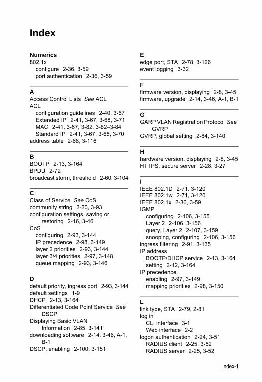
Index-1
Numerics802.1x
configure 2-36, 3-59port authentication 2-36, 3-59
AAccess Control Lists See ACLACL
configuration guidelines 2-40, 3-67Extended IP 2-41, 3-67, 3-68, 3-71MAC 2-41, 3-67, 3-82, 3-82–3-84Standard IP 2-41, 3-67, 3-68, 3-70
address table 2-68, 3-116
BBOOTP 2-13, 3-164BPDU 2-72broadcast storm, threshold 2-60, 3-104
CClass of Service See CoScommunity string 2-20, 3-93configuration settings, saving or
restoring 2-16, 3-46CoS
configuring 2-93, 3-144IP precedence 2-98, 3-149layer 2 priorities 2-93, 3-144layer 3/4 priorities 2-97, 3-148queue mapping 2-93, 3-146
Ddefault priority, ingress port 2-93, 3-144default settings 1-9DHCP 2-13, 3-164Differentiated Code Point Service See
DSCPDisplaying Basic VLAN
Information 2-85, 3-141downloading software 2-14, 3-46, A-1,
B-1DSCP, enabling 2-100, 3-151
Eedge port, STA 2-78, 3-126event logging 3-32
Ffirmware version, displaying 2-8, 3-45firmware, upgrade 2-14, 3-46, A-1, B-1
GGARP VLAN Registration Protocol See
GVRPGVRP, global setting 2-84, 3-140
Hhardware version, displaying 2-8, 3-45HTTPS, secure server 2-28, 3-27
IIEEE 802.1D 2-71, 3-120IEEE 802.1w 2-71, 3-120IEEE 802.1x 2-36, 3-59IGMP
configuring 2-106, 3-155Layer 2 2-106, 3-156query, Layer 2 2-107, 3-159snooping, configuring 2-106, 3-156
ingress filtering 2-91, 3-135IP address
BOOTP/DHCP service 2-13, 3-164setting 2-12, 3-164
IP precedenceenabling 2-97, 3-149mapping priorities 2-98, 3-150
Llink type, STA 2-79, 2-81log in
CLI interface 3-1Web interface 2-2
logon authentication 2-24, 3-51RADIUS client 2-25, 3-52RADIUS server 2-25, 3-52
Index
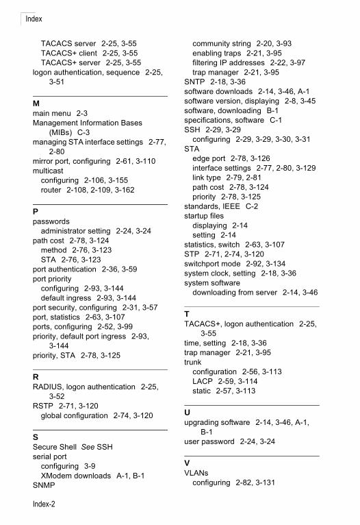
Index
Index-2
TACACS server 2-25, 3-55TACACS+ client 2-25, 3-55TACACS+ server 2-25, 3-55
logon authentication, sequence 2-25, 3-51
Mmain menu 2-3Management Information Bases
(MIBs) C-3managing STA interface settings 2-77,
2-80mirror port, configuring 2-61, 3-110multicast
configuring 2-106, 3-155router 2-108, 2-109, 3-162
Ppasswords
administrator setting 2-24, 3-24path cost 2-78, 3-124
method 2-76, 3-123STA 2-76, 3-123
port authentication 2-36, 3-59port priority
configuring 2-93, 3-144default ingress 2-93, 3-144
port security, configuring 2-31, 3-57port, statistics 2-63, 3-107ports, configuring 2-52, 3-99priority, default port ingress 2-93,
3-144priority, STA 2-78, 3-125
RRADIUS, logon authentication 2-25,
3-52RSTP 2-71, 3-120
global configuration 2-74, 3-120
SSecure Shell See SSHserial port
configuring 3-9XModem downloads A-1, B-1
SNMP
community string 2-20, 3-93enabling traps 2-21, 3-95filtering IP addresses 2-22, 3-97trap manager 2-21, 3-95
SNTP 2-18, 3-36software downloads 2-14, 3-46, A-1software version, displaying 2-8, 3-45software, downloading B-1specifications, software C-1SSH 2-29, 3-29
configuring 2-29, 3-29, 3-30, 3-31STA
edge port 2-78, 3-126interface settings 2-77, 2-80, 3-129link type 2-79, 2-81path cost 2-78, 3-124priority 2-78, 3-125
standards, IEEE C-2startup files
displaying 2-14setting 2-14
statistics, switch 2-63, 3-107STP 2-71, 2-74, 3-120switchport mode 2-92, 3-134system clock, setting 2-18, 3-36system software
downloading from server 2-14, 3-46
TTACACS+, logon authentication 2-25,
3-55time, setting 2-18, 3-36trap manager 2-21, 3-95trunk
configuration 2-56, 3-113LACP 2-59, 3-114static 2-57, 3-113
Uupgrading software 2-14, 3-46, A-1,
B-1user password 2-24, 3-24
VVLANs
configuring 2-82, 3-131

Index
Index-3
egress mode 2-92, 3-134
WWeb interface
access requirements 2-1configuration buttons 2-2
home page 2-2menu list 2-3panel display 2-3
XXModem downloads A-1, B-1

Index
Index-4


ES3526V-60150200035300AE072003-R01ES3526GE072000-R04


