Page 1
MATURATION OF AN IN VITRO
SKELETAL MUSCLE TISSUE MODEL BY
MECHANICAL STIMULATION
A Major Qualifying Project Report submitted to the faculty of
WORCESTER POLYTECHNIC INSTITUTE
in partial fulfillment of the requirements for the degree of Bachelor of Science.
Submitted by:
_______________________
Timothy Biliouris
_______________________
Gaetano Scuderi
_______________________
Craig Teed
April 29th 2016
This report represents the work of WPI undergraduate students submitted to the faculty as evidence of completion of a degree
requirement. WPI routinely publishes these reports on its website without editorial or peer review. For more information about the
projects program at WPI, please see http://www.wpi.edu/academics/ugradstudies/project-learning.html
____________________________________
Professor Raymond Page, Ph.D., Advisor
Department of Biomedical Engineering
Project ID: RLP-1501
Page 2
i
Table of Contents Chapter 1: Introduction ............................................................................................................................... 1
Chapter 2: Literature Review ...................................................................................................................... 5
2.1 Muscle Anatomy and Physiology...................................................................................................... 5
2.1.1 Brief Overview of Muscle .......................................................................................................... 5
2.1.2 Myogenesis: The Development of Skeletal Muscle ................................................................... 6
2.1.3 Native Skeletal Muscle Structure ............................................................................................... 8
2.1.4 Native Skeletal Muscle Contraction Process ............................................................................ 12
2.1.5 Muscle Contraction Factors ..................................................................................................... 16
2.1.6 Skeletal Muscle Hypertrophy ................................................................................................... 19
2.1.7 Skeletal Muscle Regeneration and Repair ................................................................................ 20
2.2 Clinical Significance ....................................................................................................................... 22
2.2.1 Muscle Atrophy ....................................................................................................................... 22
2.2.2 Muscular Dystrophy ................................................................................................................. 24
2.2.3 Volumetric Loss ....................................................................................................................... 26
2.2.4 In Vitro Tissue Engineering Applications ................................................................................ 27
2.3 Current Devices and Experiments for Mechanical Stimulation ....................................................... 30
2.3.1 Vandenburgh Mechanical Cell Stimulator ............................................................................... 31
2.3.2 Mechanical Stimulator 4.0 ....................................................................................................... 32
2.3.3 MagneTissue Bioreactor .......................................................................................................... 34
2.3.4 Main Limitations to Current Technology ................................................................................. 35
2.3.5 Prior MQP Projects in Dr. Raymond Page's Lab ...................................................................... 37
2.4 Improving the Standard for Developing Human Skeletal Muscle Tissue in vitro ........................... 42
2.4.1 Scaffolds .................................................................................................................................. 42
2.4.2 Cell Types ................................................................................................................................ 44
2.4.3 Media Types............................................................................................................................. 46
2.4.4 Mechanical Actuation of Constructs ........................................................................................ 47
Chapter 3: Project Strategy ....................................................................................................................... 48
3.1 Initial Client Statement ................................................................................................................... 48
3.2 Revised Client Statement ................................................................................................................ 49
3.3 Design Requirements (Technical) ................................................................................................... 50
3.3.1 Design Objectives .................................................................................................................... 50
3.3.2 Design Constraints ................................................................................................................... 54
3.3.3 Design Functions...................................................................................................................... 55
3.3.4 Design Parameters and Specifications ...................................................................................... 56
Page 3
ii
3.4 Design Requirements (Standards) ................................................................................................... 58
3.5 Management Strategy ..................................................................................................................... 60
Chapter 4: Design Process ........................................................................................................................ 63
4.1 Device Means ................................................................................................................................. 63
4.1.1 Proper Media Exchange ........................................................................................................... 64
4.1.2 Selection of Tissue Anchorage Point Type .............................................................................. 64
4.1.3 Displacement of Anchorage Point(s) ........................................................................................ 65
4.1.4 Controlled Strain Regimens ..................................................................................................... 66
4.2 Conceptual Device Designs ............................................................................................................ 68
4.2.1 Vertical Pin Flexible Bottom Actuator ..................................................................................... 68
4.2.2 Air Bubble Actuator ................................................................................................................. 70
4.2.3 Bottom Magnet Actuator .......................................................................................................... 71
4.2.4 Top Pin Actuator ...................................................................................................................... 73
4.2.5 Gear L-Hook Actuator ............................................................................................................. 75
4.3 Alternative Designs Prototyped Proof of Concepts ......................................................................... 76
4.3.1 Bottom Magnet Actuator Prototype ......................................................................................... 77
4.3.2 Top Pin Actuator ...................................................................................................................... 79
4.3.3 Gear L-Hook Actuator ............................................................................................................. 81
4.4 Final Design Selection .................................................................................................................... 82
4.4.1 Pugh Method Evaluation Matrix .............................................................................................. 82
4.4.2 Gear and L-Hook Modifications .............................................................................................. 84
Chapter 5: Design Verification ................................................................................................................. 93
5.1 Syringe Pump Rate Correlation ....................................................................................................... 93
5.2 Strain Calibration ............................................................................................................................ 96
5.2.1 Strain Calibration: Y-Direction (Side View) Post Deflection ................................................. 101
5.2.2 Strain Calibration: Strain Range ............................................................................................. 103
5.2.3 Strain Calibration: Device Precision Evaluation .................................................................... 104
5.3 Device Verification: Mechanical Stimulation Experiment ............................................................ 105
5.3.1 Myoblast and Fibroblast Cell Culturing Procedure ................................................................ 106
5.3.2 Fibrin Matrix-Assisted Skeletal Muscle Tissue Formation Procedure.................................... 107
5.3.3 Strain Regimen Protocol ........................................................................................................ 111
5.3.4 Histological Embedding and Staining of ESMT Constructs ................................................... 111
5.3.5 Histology Results of Mechanical Stimulation Experiment ..................................................... 113
Chapter 6: Final Design and Validation .................................................................................................. 115
6.1 Mechano-Muscle Maturation (M3) Device Final Design .............................................................. 115
Page 4
iii
6.1.1 PDMS Anchorage Posts ......................................................................................................... 116
6.1.2 96-Well Plate ......................................................................................................................... 118
6.1.3 Cover Parts ............................................................................................................................. 119
6.1.4 L-hook Pin and Wheel System ............................................................................................... 122
6.1.5 Grid System ........................................................................................................................... 123
6.1.6 Device Function ..................................................................................................................... 125
6.3 Project Impact ............................................................................................................................... 127
6.3.1 Economics .............................................................................................................................. 127
6.3.2 Environmental Impact ............................................................................................................ 128
6.3.3 Societal Influence ................................................................................................................... 128
6.3.4 Political Ramifications ........................................................................................................... 129
6.3.5 Ethical Concerns .................................................................................................................... 129
6.10.6 Health and Safety Issues ...................................................................................................... 130
6.3.7 Manufacturability ................................................................................................................... 130
6.3.8 Sustainability.......................................................................................................................... 131
Chapter 7: Discussion ............................................................................................................................. 132
7.1 General Discussion of Results....................................................................................................... 132
7.2 Comparison to Gold-Standard ....................................................................................................... 134
7.3 Comparing Final Design to Objectives ......................................................................................... 137
7.4 Comparing Final Design to Constraints ........................................................................................ 138
7.5 Limitations to Data ....................................................................................................................... 140
Chapter 8: Conclusions and Recommendations ...................................................................................... 142
8.1 Conclusions ................................................................................................................................... 142
8.2 Recommendations ......................................................................................................................... 143
References .............................................................................................................................................. 147
Appendix A: Final Device Drawings and Images ................................................................................... 150
Appendix B: Final Device Standard Operating Procedure ...................................................................... 167
Appendix C: Syringe Pump Rate Correlation Results Table ................................................................... 176
Appendix D: Bill of Materials ................................................................................................................ 177
Page 5
iv
Table of Figures
Figure 1: Hierarchical structure of skeletal muscle showing the connective tissue sheaths, individual
muscle fibers, bundles of muscle fibers called fascicles, and bundles of fascicles that make up the entire
skeletal muscle tissue [11] .......................................................................................................................... 9
Figure 2: Basic functional unit of skeletal muscle with myosin and actin myofilaments [12]. .................. 10
Figure 3: Process of neuromuscular junction signaling demonstrating how an action potential travels
from a neuron’s axon into a muscle fiber [11] .......................................................................................... 13
Figure 4: T-Tubules Involved in Excitation Contraction Coupling [11] ................................................... 14
Figure 5: Components of the cross-bridge cycle showing the thick filaments of myosin with the two
globular heads for actin binding, the thin filaments of actin with troponin and tropomyosin and the
arrangement of the thick and thin filaments within a sarcomere [11] ...................................................... 16
Figure 6: Length-Tension Relationship of Sarcomeres [11] ..................................................................... 17
Figure 7: Representation of Concentric, Eccentric, and Isometric Contractions [11] ............................. 19
Figure 8: Difference of healthy and muscular dystrophy skeletal muscle tissue [25] ............................... 24
Figure 9: Comparison of Control (no anchorage points), Unstrained (no mechanical stimulation),
Strained (mechanical stimulation), with a MHC stain of the myosin heavy chain proteins and DAPI stain
of the nuclei [6] ........................................................................................................................................ 30
Figure 10: Vandenburgh Mechanical Cell Stimulator, showing the device as well as a uniaxial-dimension
comparison between "control" and "stretch" states [1] ............................................................................ 32
Figure 11: Mechanical Cell Stimulator 4.0 showing size well plates with hBAM tissues developing around
two attachment sites [5] ............................................................................................................................ 33
Figure 12: MagneTissue Bioreactor showing the tube, spool-hook system and bioreactor set-up [6] ..... 34
Figure 13: Comparison of mechanically stimulated 3D in vitro ESMT using the MagneTissue Bioreactor
and Native Skeletal Muscle [6]. ................................................................................................................ 35
Figure 14: RLP 1401's Mechanical Stimulation Device with two platforms that which the ESMT on the
molds were placed [31]. ........................................................................................................................... 39
Figure 15: RLP 1402's Mechanical Stimulation Design with a movable post shown in the zoomed portion
of the image. The lid of the device is not shown [34] ................................................................................ 40
Figure 16: Primary (red rectangles) and secondary objectives (dark blue ovals) .................................... 52
Figure 17: Work Breakdown Structure with goals (blue rectangles) and subgoals (white rectangles) ..... 60
Figure 18: Gantt chart that organizes major milestones .......................................................................... 62
Figure 19: Syringe pump hydraulic system technique from RLP1402 [34] .............................................. 68
Figure 20: Vertical Pin Flexible Bottom Actuator showing unstrained (left) and strained (right) ........... 69
Figure 21: Air Bubble Actuator with flexible bottom wells inflated by air flow to deflect posts ............... 70
Figure 22: Magnet on Bottom Actuator that moves metal encased post on a track .................................. 72
Figure 23: Top Pin Actuator showing a pin connected to small movable post on a track that allows for
linear movement of post ............................................................................................................................ 74
Figure 24: Gear L-Hook Actuator showing a gear system that turns L-hooks to deflect flexible posts..... 75
Figure 25: Bottom Magnet Actuator prototype with wheels to reduce friction ......................................... 79
Figure 26: Top Pin Actuator Prototype .................................................................................................... 80
Figure 27: Gear L-Hook Actuator Prototype ............................................................................................ 81
Figure 28: Rotation component with grooved wheel, rubber O-ring, cylinder, and L-hook pin ............... 86
Figure 29: PDMS post anchorage point modification to allow for the L-hook to deflect the post above the
tissue ......................................................................................................................................................... 87
Page 6
v
Figure 30: PDMS post deflection diagram for prediction model. Red arrow represents change in tissue
displacement. Blue arrow represents L-hook pin displacement. A represents height at which L-hook pin
hits the post. B represents the height of the tissue. .................................................................................... 88
Figure 31: Top view of L-hook pin head (horizontal bent portion of L shape) and PDMS post. Grey
circles represents the PDMS post deflection from top view. Blue arrow represents the pin displacement.
Dotted black line represents the L-hook pin head before rotation and the solid black line represents the L-
hook pin after rotation and deflection of PDMS post. ............................................................................... 89
Figure 32: Mechano-Muscle Maturation Device fully assembled CAD drawing ...................................... 90
Figure 33: Functional flow diagram of final design ................................................................................. 91
Figure 34: Output flow rate versus input flow rate with blue data points, red trend line and R2 value =
0.9982 ....................................................................................................................................................... 95
Figure 35: 96 well plate cut to expose inside of two wells. Exposed wells contain anchorage points with
black marked caps .................................................................................................................................... 96
Figure 36: Representative images of trial 3 showing post deflection with L-hook. The line indicates the
length of the tissue. The global length was set to the 0.50 mm diameter of the L-hook in Image J. .......... 97
Figure 37: Normalized strain calibration for all four trials and average. Plot of normalized strain versus
volume of dispensed mineral oil (mL) with corresponding average trend line and R2 value. .................... 98
Figure 38: Trial 2 and trial 3 normalized strain calibration for dispensed and withdrawn mineral oil ... 99
Figure 39: Plot of average normalized strain versus volume of dispensed/withdrawn mineral oil (mL) for
trial 2 and trial 3. Withdraw average trend line, linear equation and R2 value are shown in the graph. 100
Figure 40: Pythagorean Theorem to determine the real “new” displacement of the tissue with
corresponding equations to determine displacement length and strain error ......................................... 102
Figure 41: Strain range of device showing L-hooks deflecting posts within two individual wells of a 96-
well plate. A) Minimum strain as shown by the inward deflection of the posts. B) Maximum strain of
device as shown by outward deflection of the post as it hits the well wall. All pictures contain blue line
that represents the length between the two posts. 0.80 mm diameter of the post was used as the global
measurement for all Image J analysis. .................................................................................................... 104
Figure 42: Tissue formation flow diagram showing all steps in the procedure (adapted from [48]) ...... 108
Figure 43: Three ESMT anchored to PDMS posts within a 96 well plate. Also zoomed in representative
image depicting contiguous three dimensional ESMT ............................................................................ 110
Figure 44: H&E stain of C2C12 ESMT at 5X magnification. A) Static, non-mechanically stimulated
control ESMT. B) Mechanically stimulated ESMT.................................................................................. 113
Figure 45: Fully assembled Mechano-Muscle Maturation Device final design with all components except
attached syringe ...................................................................................................................................... 116
Figure 46: PDMS posts for tissue anchorage points with corresponding dimensions ............................ 117
Figure 47: Modified PDMS post anchorage points ................................................................................ 118
Figure 48: Standard 96-well plate with PDMS anchorage points glued into bottom of each well .......... 119
Figure 49: Delrin cover with 0.5 mm diameter clearance holes, track for grid system and syringe pump
attachment .............................................................................................................................................. 120
Figure 50: Top component that fits on top cover with slit for syringe attachment .................................. 121
Figure 51: L-hook pin with attached grooved wheel, rubber O-ring, and small cylinder ....................... 123
Figure 52: Grid system with slit for syringe attachment ......................................................................... 124
Figure 53: Functional flow diagram demonstrating how all components of final device interact to allow
for deflection of the PDMS posts to strain the tissue............................................................................... 126
Figure 54: NIPAAm Stamp Mold conceptual design for one well of a 96-well plate .............................. 145
Figure 55: NIPAAm Stamp Mold within one well of a 96-well plate around the PDMS posts ................ 146
Page 7
vi
Table of Tables
Table 1: Comparison of native and gold-standard in vitro skeletal muscle (from [4], [5], and [1]) ........ 29
Table 2: Construct quantity, cell density, construct length, and anchorage type for MagneTissue
Bioreactor [6], Vandenburgh Mechanical Cell Stimulator [1], and Mechanical Cell Stimulator 4.0 [5]
compared to the ideal parameters for ESMT constructs ........................................................................... 37
Table 3: Strain Regimens of RLP 1401 [31]. ............................................................................................ 42
Table 4: Pairwise comparison chart of primary objectives ...................................................................... 51
Table 5: Device specifications showing the desired mechanical stimulation parameters for the device ... 57
Table 6: Tissue construct specifications for contiguous minimal functional units of ESMT ..................... 58
Table 7: Standards associated with the mechanical stimulation device .................................................... 58
Table 8: Functions-Means table for mechanical stimulation device ......................................................... 63
Table 9: Pugh method evaluation matrix for deciding device design. The numbers in parentheses
represent the weighted scores multiplied by the compared rankings to the baseline. ............................... 83
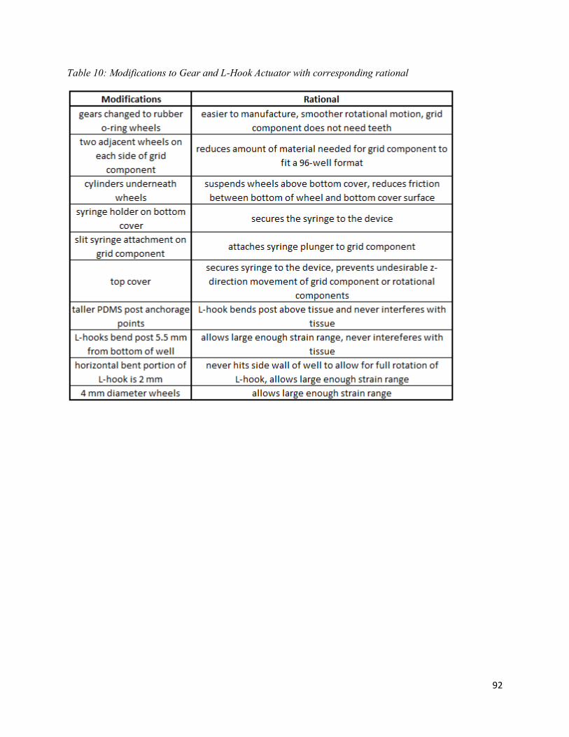
Table 10: Modifications to Gear and L-Hook Actuator with corresponding rational ............................... 92
Table 11: Four trials with dispensed mineral oil (mL), corresponding strain (%), and normalized strain
(%).The average and standard deviation of normalized strain for all four trials were also calculated .... 98
Table 12: Withdraw trial 2 and trial 3 showing volume of withdrawn mineral oil (mL), corresponding
strain, and normalized strain. Normalized strain average of both trials for dispensed mineral oil and
withdrawn mineral oil is also included. .................................................................................................. 101
Table 13: Side view trial and front view trial 2 results showing volume of dispensed mineral oil (mL),
normalized deflections (mm), and two-dimensional stretch when combining front and side view trials with
corresponding strain and strain error .................................................................................................... 103
Table 14: Eight trials of post deflection after 0.6 mL of dispensed mineral oil. Final displacement (length
in mm) and strain percentage are shown. The initial length between the posts were determined to be 2.25
mm. ......................................................................................................................................................... 105
Table 15: Strain regimen protocol used within mechanical stimulation experiments ............................. 111
Table 16: Comparison of Mechano-Muscle Maturation Device (team’s design) to Mechanical Stimulator
4.0 (gold-standard) [5]. .......................................................................................................................... 136
Page 8
vii
Authorship
Chapter Main Author(s) Editor(s) Chapter 1: Introduction Everyone Everyone
Chapter 2: Literature Review
2.1 Muscle Anatomy and Physiology Gaetano Scuderi Everyone
2.2 Clinical Significance Timothy Biliouris Everyone
2.3 Current Devices and Experiments for Mechanical
Stimulation
Craig Teed and Gaetano
Scuderi
Everyone
2.4 Improving the Standard for Developing Human
Skeletal Muscle In Vitro
Craig Teed Everyone
Chapter 3: Project Strategy
3.1 Initial Client Statement Craig Teed Everyone
3.2 Revised Client Statement Everyone Everyone
3.3 Design Requirements (Technical) Everyone Everyone
3.4 Design Requirements (Standard) Gaetano Scuderi Everyone
3.5 Management Strategy Timothy Biliouris Everyone
Chapter 4: Design Process
4.1 Device Means Gaetano Scuderi Everyone
4.2 Conceptual Device Designs Craig Teed and Timothy
Biliouris
Everyone
4.3 Alternative Designs Prototyped Proof-of-Concept Timothy Biliouris and
Gaetano Scuderi
Everyone
4.4 Final Design Selection Gaetano Scuderi Everyone
Chapter 5: Design Verification
5.1 Syringe Pump Rate Correlation Craig Teed Everyone
5.2 Strain Calibration Gaetano Scuderi Everyone
5.3 Device Verification: Mechanical Stimulation Experiment
Gaetano Scuderi Everyone
Chapter 6: Final Design and Validation
6.1 Mechano-Muscle Maturation (M3) Device Final
Design
Tim Biliouris Everyone
6.2 Comparison to Industry Standards Gaetano Scuderi Everyone
6.3 Project Impact Craig Teed and Gaetano
Scuderi
Everyone
Chapter 7: Discussion
7.1 General Discussion of Results Gaetano Scuderi Everyone
7.2 Comparison to Gold-Standard Gaetano Scuderi Everyone
7.3 Comparing Final Design to Objectives Craig Teed Everyone
7.4 Comparing Final Design to Constraints Craig Teed Everyone
7.5 Limitations to Data Gaetano Scuderi Everyone
Chapter 8: Conclusion and Recommendations Craig Teed Everyone
Page 9
viii
Acknowledgements
The team would like to thank Professor Raymond Page and Jason Forte for their assistance and
guidance throughout the duration of this project. The team would also like to express our
gratitude to Tom Partington, WPI’s Goddard Hall machinist, who helped manufacture a variety
of parts for our final design. Lastly, the team would like to thank Lisa Wall, WPI’s biomedical
engineering lab manager, for providing the team with a variety of lab equipment and supplies in
order to complete this project.
Page 10
ix
Abstract
Whether searching for cures of muscular diseases or testing the potential muscle side
effects of new therapeutics that are developed to treat any conditions, there remains no
biomimetic in vitro skeletal muscle tissue model that precisely mimics native human muscle
morphology and function, due to a lack of maturation. Animal models also fail to provide
clinically-relevant results since they do not effectively recapitulate muscular disease and lack
genetic homology to humans. Due to the lack of an accurate human skeletal muscle model, drug
efficacy and drug’s potential side effects on muscle cannot be tested pre-clinically, which can
lead up to a 90% failure rate for drug in human clinical trials. To better improve the in vitro
maturation of skeletal muscle tissue models and thus create a more clinically relevant models, a
mechanical stimulation device was developed. This device fits any standard 96-well plate and
uses a hydraulic syringe pump to simultaneously strain ninety-six 3-4 mm constructs, long-term
within an incubator. The system provides a higher throughput and is more efficient than the
current gold-standard. The project team validated that the device works properly and utilized
ImageJ software to determine that the device is capable of straining the tissues in the range of -
50% to +25% with a strong linear correlation between the volume of dispensed mineral oil by the
syringe pump and the resultant strain on the engineered tissue. The device effectively provided a
morphological difference in mouse C2C12 myoblasts as well as primary human myoblast
derived tissue constructs. The mechanically stimulated constructs yielded better myotube
alignment and less necrosis compared to the static (control) constructs.
Page 11
1
Chapter 1: Introduction
Skeletal muscle plays a vital role in the function of body movement. However, muscle
function can be significantly limited or even inhibited by conditions such as volumetric loss or
myopathies. Muscular diseases such as Muscular Dystrophy (MD) gradually deteriorate targeted
muscle tissue, depriving those who suffer from it the ability to live a normal life [1]. In 2009,
Duchenne Muscular Dystrophy affected one out of every 3,600 males between the ages of five
and twenty-four in the United States, with a 100% fatality by the age of twenty-four [2]. There is
currently no cure for the various types of Muscular Dystrophy. With limited treatments available
for these fatal conditions, there remains a significant need for further research to develop
possible cures.
Animal skeletal muscle tissue is the ideal platform for conducting research for therapeutic
treatments. However, primate genetic diseases, such as DMD, cannot be modeled in smaller
animal systems since they fail to accurately recapitulate the disease and only emulate the
symptoms of the disease. Therefore, the current method for treatment research for conditions
such as DMD in human skeletal muscle is performed through in vitro culturing of engineered
human skeletal muscle tissue (ESMT) [3]. An in vitro model of human skeletal muscle tissue
allows for research on the effects of many diseases and drugs to take place without harming a
living patient [3]. This benchtop testing method is a promising option through which researchers
may develop treatments for curing myopathies, muscle atrophy, and muscle-related ailments [3].
Although engineered in vitro skeletal muscle tissue is considered to be the next step in
research, the engineered tissue has not achieved the same properties of native adult skeletal
muscle tissue [4]. ESMT have smaller myotube diameters and lower muscle fiber densities,
which are not functional units that are comparable to native tissue [1]. Without comparable
Page 12
2
properties, the ESMT cannot be used as accurate and useful substitutes for adult muscle tissue in
research for muscular disease.
One way to improve upon the current ESMT is through mechanical stimulation.
Mechanical stimulation of the engineered muscle tissue has shown to decrease the level of
discrepancy by increasing the muscle fiber size, diameter, and density [1]. Current technology
has shown progress in increasing the in vitro maturation through regimens of uniaxial strain and
by using two anchorage posts that simulate bone attachment sites [1]. This method better
represents the linear fiber alignment environment of native skeletal muscle tissue [1]. However,
ESMT remains essentially not comparable in form to adult skeletal muscle tissue in morphology
and strength. The strength of ESMT range from 1-10% the strength of native skeletal muscle [4].
Thus, an improvement in mechanical stimulators for this engineered tissue and further improved
procedures for developing the constructs present a significant clinical need worth addressing.
The currently technology for producing ESMT in vitro has been approached in several
different ways in previous devices, from incorporating additives to the culture media that can
improve secretion of extracellular matrix (ECM) to varying strain regimens over time as the
constructs mature. However, previous devices did not maximize the number of constructs
produced, nor did they produce tissues that had comparable functional strength or alignment to
those produced naturally in vivo. It is postulated that improvements are possible with regards to
the microenvironment in which the constructs are placed in, the self-assembly pattern chosen for
growing the tissues, the cell types used, and the precise strain regimens employed. Based on the
primary source literature analyzed further in the next chapter, it is clear that there is still room for
improvement in both the device design aspect and the procedural details involved in producing
more functional models of human skeletal muscle tissue in vitro.
Page 13
3
In order to address the need for this project, the team established goals to develop in vitro
skeletal muscle tissue that more closely resembles native skeletal muscle tissue and serve as a
more accurate model for muscular diseases. The first main project goal was to grow skeletal
muscle tissue in vitro using a three dimensional construct that will mimic in vivo conditions
while also providing anchorage points similar to those found in vivo. The second goal is to
engineer a means to mechanically stimulate the tissue in vitro that will improve the maturation
process while functioning in an incubator and be integrated with the tissue constructs. After
creating a reliable mechanical stimulation device, the next goal is to measure the protein
production of the constructs in order to further quantify the maturity of the ESMT.
The team planned to effectively address the goals developed for this project through a
design approach that involved developing a superior mechanical stimulator using a re-designed
96-well plate format. Additionally, the team planned to carefully select ideal media formulations
based on the materials used for the device, cell types cultured, and actuation regimens employed.
The expectation was established that the designed system would successfully emulate native
development and maturation of human skeletal muscle tissue and would produce tissues that
exhibit an increase in several maturation indicators compared to a gold-standard mechanical
stimulation device for in vitro ESMT.
To meet the goals of the project, several metrics of success were established. First, the
device needed to be capable of providing repeatable mechanical stimulation. The stimulation
regimens needed to be precise, accurate, and consistent from one experiment to the next in order
to obtain reliable results. Another metric was the ability to grow and develop ESMT that are
more mature than currently produced constructs. This maturation was assessed based on four
maturation indicators: myotube alignment, myotubes diameter, percentage of myosin, and
Page 14
4
number of nuclei per myotubes and compared to the gold-standard mechanical stimulation
device by Powell et al. [5]. According to the primary literature, the myotubes should be aligned
about a strain axis and have minimal degrees of deviation from that axis of strain to allow for
coordinated muscle contraction [6]. The myotube diameter should be greater than 7 µm which
was presented by Powell et al. and become closer to the 100 µm diameter of native skeletal
muscle tissue [1]. Myosin is a significant myogenic protein that is involved in the functional
contraction of skeletal muscle; therefore, a greater presence of myosin indicates greater
maturation [7]. The percentage of myosin, or amount of myosin within a given area, should
exceed the gold standard of 10.9% and be approaching the 90% found in native [5]. Lastly, the
number of nuclei per myotubes is a maturation indicator since myoblasts fuse together into
multinucleated myotubes during differentiation and maturation [6]. Overall, these metrics were
used to help drive the project forward to meet the goals that were set forth by the team and the
client.
The next chapter of this report provides a literature review and discusses a variety of
topics related to skeletal muscle tissue and mechanical stimulation. The chapter addresses the
overall need for this project by examining a variety of muscular diseases and their
pathophysiology. The chapter also explains the intricate physiological processes of in vivo
muscle proliferation, differentiation, and maturation. Lastly, the current tissue engineering
process for developing in vitro skeletal muscle tissue is discussed, as well as the overall
limitations and need for improvements. The need for improvements is highlighted by comparing
native skeletal muscle tissue to the current state-of-the-art engineered tissue constructs. Lastly,
the chapter reviews mechanical stimulation protocols and devices and their significance in the
maturation of ESMT.
Page 15
5
Chapter 2: Literature Review
The following chapter contains pertinent background information on human skeletal
muscle tissue. The information in the following sections includes anatomical composition and
function of skeletal muscle tissue, the clinical need for an improved in vitro model for human
skeletal muscle tissue, and examples of devices that have been previously developed to produce
and mature skeletal muscle tissue constructs using mechanical stimulation. Through extensive
research into related primary research literature, the ideal conditions and characteristics derived
from biological phenomena and experiments were determined in an effort to develop a model
that produces tissue that exhibits more native-like characteristics than previous ESMT.
2.1 Muscle Anatomy and Physiology
Before developing a device to mechanically stimulate tissue engineered skeletal muscle
in vitro, the anatomy and physiology of native skeletal muscle in vivo must be understood. By
mimicking de novo muscle synthesis and endogenous repair, better ESMT can be developed that
more closely resemble native skeletal muscle.
2.1.1 Brief Overview of Muscle
The need for a tissue engineered skeletal muscle model cannot be fully apprehended
without first understanding the physiology and anatomy behind native skeletal muscle. There are
three main types of muscle throughout the body: 1) cardiac, 2) smooth, and 3) skeletal muscle.
The third type, skeletal muscle, is the most prevalent form of tissue found in the human body,
making up between 40-50% of the body’s tissue [7]. Skeletal muscle is attached to tendons and
bones throughout the entire body and is the only type of muscle tissue that is controlled
voluntarily. Skeletal muscles help to maintain posture and position, provide stability for joints,
generate heat during contraction, and protect internal organs from impact. However, the main
Page 16
6
function of skeletal muscle is voluntary movement. Through the use of intricate contractions and
thus the shortening of the muscle fibers, skeletal muscle provides many organisms the ability to
move voluntarily. Due to its diverse and significant physiological functions, skeletal muscle is
exceptionally critical to the survival and well-being of many organisms [7].
2.1.2 Myogenesis: The Development of Skeletal Muscle
The process of native skeletal muscle development in vivo must be fully understood in
order to help learn how to develop in vitro skeletal muscle tissue. During embryonic
development, skeletal muscle tissue begins to form through a process called myogenesis. When
myogenesis signaling begins, muscle progenitor cells begin to migrate to various areas of the
developing fetus to differentiate and develop into functional skeletal muscle tissue [8].
The overall basic process of myogenesis involves three intricate phases: 1) the
determination phase, 2) the terminal differentiation phase, and 3) the maturation phase. During
the determination phase, muscle progenitor cells commit to the muscle lineage and therefore
become myoblasts. Then the myoblasts begin to fuse together into multinucleated, early
myotubes throughout the terminal differentiation phase [9]. These early myotubes slowly begin
to mature into highly aligned muscle fibers during the maturation phase after being stimulated
mechanically and electrically in vivo [10].Through this maturation phase, skeletal muscle fibers
obtain their useful functionality [10].
All three phases of myogenesis involve a complex variety of genetic transcription factors
that are essential to the development of skeletal muscle tissue. The first step of myogenesis
occurs when myogenic factor 5 (Myf5) activates myogenic differentiation antigen (MyoD) [9].
MyoD activation has shown to help facilitate the expression of a variety of muscle specific
genes, which influence the muscle progenitor cells to commit to the determination phase and
Page 17
7
thus become myoblasts [9]. Various studies done on the embryonic development of mice have
shown that the absence of MyoD and Myf5 directly leads to the improper development of muscle
[9]. Both factors are necessary for the muscle progenitor cells to commit to the skeletal muscle
lineage and express muscle specific genes [9]. Thus, MyoD and Myf5 are imperative factors
involved with myogenesis [9]. Studies have also shown that the myogenic regulatory factor
(MRF4) is another transcription factor that is involved in the determination phase [9]. The last
notable contributor to the determination phase is the gene Pax3 as it is associated with the
migration of the muscle precursor cells [8].
After committing to myoblasts, myogenin, has a large responsibility throughout the
terminal differentiation phase to help myoblasts fuse together into early myotubes [9]. Myocyte
enhancer factor 2 (Mef2) also plays a role throughout the terminal differentiation phase to assist
the expression of a variety of muscle specific genes, to further mediate myoblast fusion [9]. The
terminal differentiation phase also coincides with bone and tendon development [10]. During the
phase, muscle attach to tendons and bones and begin to align due to axial straining, which
coincides with the last phase, maturation [10].
Once the early myotubes have formed, the maturation phase occurs when the myotubes
become innervated, vascularized, and tension is applied to developing muscle [10]. Throughout
this phase, the early myotubes mature into highly aligned muscle fibers with an increased
diameter size and greater fiber density, which increases their overall contractile strength [10].
The innervation provides electrical stimulation by nerve impulses to the muscle tissue, which
allows for the muscle to further mature and contract [10]. Vascularization provides the
developing muscle tissue the necessary nutrients for viability and proliferation [10]. Overall,
embryogenesis plays a vital role in the maturation of skeletal muscle cells. During
Page 18
8
embryogenesis, the elongation of bone, due to bone development, causes passive mechanical
forces to be applied to the maturing muscle that is attached to tendon and bone at its ends since
opposing muscles are under tension [1]. The axial straining on the muscle fibers allow for greater
muscle fiber alignment and thus greater maturation [10]. Postnatally, muscles are also constantly
being mechanically stimulated, which further improves the maturation of the muscle fibers [1].
2.1.3 Native Skeletal Muscle Structure
Native skeletal muscle’s hierarchical structure is what provides muscle with its unique
contractile properties. Therefore, understanding this structure is an essential step to
understanding the functionality of muscle. Native skeletal muscle is organized in the following
hierarchical order from largest to smallest: whole muscle tissue, fascicle, myofibril, sarcomere,
and myofilament, as shown in Figure 1. An entire muscle tissue is made up of a group of muscle
fibers, called a fascicle, that are connected through a variety of connective tissue sheaths. Muscle
fibers contain long cylindrical, multinucleated cells, called myocytes, as well as thousands of
dense fibers called myofibrils. These myofibrils make up about 80% of the entire muscle cell
volume. Surrounding each of the myofibrils, exists the sarcoplasmic reticulum, which is the
muscle’s specialized endoplasmic reticulum that stores calcium ions for muscle contractions [7].
Page 19
9
Figure 1: Hierarchical structure of skeletal muscle showing the connective tissue sheaths, individual
muscle fibers, bundles of muscle fibers called fascicles, and bundles of fascicles that make up the entire
skeletal muscle tissue [11]
Each muscle fiber contains repeating units of sarcomeres, which are considered the
skeletal muscle functional unit of contraction [7]. These sarcomeres are striated, meaning they
contain dark and light bands, which is a prominent feature of muscle tissue [7]. Within each
sarcomere, there are thick and thin myofilaments, which give the sarcomere its striated
appearance and are what allow for a muscle contractions to occur [7]. Thick filaments, which are
composed of the protein myosin, contain two globular heads that attach to the thin filaments
during a contraction [7]. Thin filaments are composed of a twisted, double stranded protein
called actin [7]. During a contraction, the thin filaments slide across the thick filaments towards
the center of the sarcomere and shorten [7]. Therefore, the alignment of the thick and thin
Page 20
10
filaments within a sarcomere are essential to the contractile functionality of skeletal muscle
tissue [7]. The structure of a sarcomere can be seen in Figure 2.
Figure 2: Basic functional unit of skeletal muscle with myosin and actin myofilaments [12].
The extracellular matrix (ECM) surrounding muscle fibers plays an integral role in the
functionality of skeletal muscle because it bares much of the muscle’s passive load [13]. The
proteins within skeletal muscle ECM can be quantified and used as benchmarks to quantify the
development and maturation of in vitro skeletal muscle tissue. The ECM also provides a natural
scaffold that allows for the skeletal muscle to develop in an organized fashion [13]. Surrounding
the muscle tissue is a hierarchy of connective tissue sheaths. The epimysium is a dense irregular
connective tissue that surrounds the entire muscle tissue and all its corresponding fascicles [7].
Surrounding the fascicles of muscle is a fibrous connective tissue sheath called the perimysium
[7]. This perimysium is made up of transverse collagen fibers [13]. The last main connective
tissue sheath is called the endomysium, which is a fine areolar connective tissue that surrounds
each of the individual muscle fibers [7]. Therefore, this hierarchy of connective tissue sheaths
provides skeletal muscle tissue with organization and structure that is necessary for proper
aligned contractions to occur. Overall, collagen makes up about one to ten percent of the mass of
muscle [7].The connective tissue sheaths are mainly composed of type I and type III collagen but
types four, five, six, eleven, twelve, fourteen, fifteen and eighteen collagen are also present
Page 21
11
within the extracellular matrix of skeletal muscle [7]. Type four collagen makes up the basement
membrane of skeletal muscle [7].
Besides the connective tissue sheaths and collagen, there are several other substances that
make up the ECM of muscle that play an influential role in the muscle’s functionality and
development [13]. Proteoglycans are a major contributor to the ECM [13]. They can store and
release growth factors that may help facilitate myogenesis [13]. The major proteoglycans within
muscle ECM are a family of small leucine-rich proteoglycans (SLRPs), such as decorin and
biglycan [13]. Proteoglycans can bind to collagen at specific, various locations and therefore
play an influential role in the muscle ECM’s overall organization and structure [13]. Also, the
absence of biglycan or decorin is directly related to a reduction in the mechanical properties of
skeletal muscle and therefore are important proteoglycans in the function of skeletal muscle
tissue [13]. Glycoproteins also play an influential role. The glycoprotein, laminin, can bind to
type IV collagen and therefore is an important molecule in the structure of the muscle’s
basement membrane [13]. Metalloproteinase, which are matrix remodeling enzymes, are also
present within the ECM [13]. These enzymes help to degrade and deposit new ECM [13]. These
enzymes are needed for cell migration and formation of myotubes and thus play a role in
myogenesis and muscle repair as well [13]. The last main contributing factor to the ECM are
fibroblasts [13]. Fibroblasts are responsible for producing a majority of the ECM components
and are needed to help organize the ECM of the muscle tissue [13]. These components of the
ECM provide more structure for the skeletal muscle tissue and therefore increase its overall
functionality [13]. Understanding the ECM of native skeletal muscle tissue is essential,
especially when developing tissue engineered skeletal muscle in vitro that requires a scaffold to
Page 22
12
develop and mature into highly aligned muscle fibers [10]. Also the ECM proteins can be used as
benchmarks for this project since their presence indicates mature skeletal muscle fibers.
2.1.4 Native Skeletal Muscle Contraction Process
Before developing a device that will mechanically stimulate skeletal muscle tissue, one
must first understand how native skeletal muscle tissue contracts. There are three main processes
that lead to skeletal muscle contraction: 1) signaling at the neuromuscular junction, 2) excitation-
contraction coupling and 3) cross bridge cycle [7]. The signaling at the neuromuscular junction
transfers the action potential from the motor neuron to the muscle fiber [7]. The excitation-
contraction coupling converts the electrical signal of the action potential that travels down the
muscle fiber into a mechanical force of contraction [7]. Lastly, the cross bridge cycle is the
molecular level of contraction that occurs from the sliding of the thick and thin filaments [7].
The signaling at the neuromuscular junction allows for communication between motor
neurons, which innervate the muscle fibers, and the muscle fibers themselves. As shown in
Figure 3, the entire process involves several intricate steps.
Page 23
13
Figure 3: Process of neuromuscular junction signaling demonstrating how an action potential
travels from a neuron’s axon into a muscle fiber [11]
During neuromuscular junction signaling, an action potential propagates down a motor
neuron and arrives at the axon terminal, which is the end of the motor neuron [7]. This change in
voltage stimulates the opening of voltage gate calcium channels, which leads to calcium ions
entering the axon terminal [7]. With the influx of calcium ions, synaptic vesicles which contain
the neurotransmitter acetylcholine, begin to exocytose into the synaptic cleft, which is the gap
between the axon terminal and the motor end plate of the muscle fiber [7]. Acetylcholine diffuses
Page 24
14
across this synaptic cleft and then binds to receptors of acetylcholine on the cell membrane of the
muscle fiber, called the sarcolemma [7]. This binding of the acetylcholine causes the opening of
ion channels at the motor end plate and thus an end plate potential, or local depolarization,
occurs [7]. This depolarization triggers an action potential to occur within the muscle fiber’s
sarcolemma [7].
Once the action potential begins within the muscle fiber, the excitation-contraction
coupling process converts the electrical signal of the action potential into an actual muscle
contraction. The action potential moves down the transverse tubules, which are tubes that extend
within the muscle fibers, as shown in Figure 4. This change in voltage within the tubules causes
voltage sensitive tubule proteins to transform shape and leads to the opening of calcium release
channels within the sarcoplasmic reticulum. Calcium ions then influx the cytosol of the muscle
fiber and bind to the protein troponin on the actin thin myofilaments. This binding of calcium to
troponin causes tropomyosin to unblock its myosin-actin binding site and leads to a contraction
through the cross-bridge cycle process [7].
Figure 4: T-Tubules Involved in Excitation Contraction Coupling [11]
Page 25
15
The cross-bridge cycle is the sliding of the thin filaments across the thick filaments,
which shortens the sarcomere and thus leads to a contraction, as shown in Figure 5. After the
unblocking of the actin-myosin binding site, the myosin globular heads of thick filaments attach
to the actin myofilaments to form a cross-bridge. The unbinding of ADP and phosphate from
myosin causes the myosin heads to perform a power stroke where they pivot and pull the actin
thin filaments closer to the center of the sarcomere. This shortening of the sarcomere is a muscle
contraction. After the power stroke, ATP binds to myosin, which causes the globular heads to
disengage from the thin filaments. Once ATP is hydrolyzed into ADP and phosphate, the myosin
head returns to its pre-power stroke shape. This entire cross-bridge cycle will continue as long as
there are calcium ions and ATP present within the muscle fiber to allow for the cycle to occur.
Therefore, calcium ions are an essential ion that is needed for muscle contractions [7]. The thick
and thin filaments of a sarcomere and the intricate components that are involved in the cross-
bridge cycle can be seen in Figure 5.
Page 26
16
Figure 5: Components of the cross-bridge cycle showing the thick filaments of myosin with the
two globular heads for actin binding, the thin filaments of actin with troponin and tropomyosin
and the arrangement of the thick and thin filaments within a sarcomere [11]
2.1.5 Muscle Contraction Factors
Besides understanding the steps that lead to a contraction, one must also understand the
factors that influence the strength of a contraction in native skeletal muscle. There are four main
factors involved in the force of muscle contractions: 1) motor unit recruitment, 2) muscle length
to tension ratio, 3) frequency of muscle stimulation, and 4) size of muscle fibers [7]. By
changing the stimulus strength and frequency, native skeletal muscles are able to control the
degree of muscle contractions [7]. Individual muscle fibers contract by an all or nothing effect
because nerves only innervate individual muscle fibers, which are a portion of the muscle [7].
Therefore, in order to increase the strength of a contraction, more motor units, which consist of
the motor neuron and the muscle fibers that the motor neuron innervates, must be recruited to
contract [7]. According to the size principle of motor unit recruitment, the smallest motor units
Page 27
17
are recruited first and then as the need for larger forces increases, larger and larger motor units
are recruited [7]. This size principle allows varying degrees of muscle contraction [7]. Also
motor unit recruitments occur in an asynchronous fashion to postpone muscle fatigue since it
allows some muscle fibers to relax and recover while others are in maximal tension [7].
The degree of muscle stretch is another influential factor in muscle contraction. Muscles
have an ideal length-tension relationship where the myofilaments overlap an optimal amount to
allow for the greatest contraction to occur [7]. If muscle are stretched or shortened too much, the
thin filaments will not be able to slide past the thick filaments optimally and thus the resulting
force of contraction will be reduced [7]. Therefore, the correct ratio of length to tension must be
provided to allow for an optimal contractile performance [7]. The ideal length of a sarcomere is
around 80-120% the initial length of the sarcomere, as shown in Figure 6 below [11]. This
length-tension relationship is an important factor in the contractile force capabilities of the
muscle fibers.
Figure 6: Length-Tension Relationship of Sarcomeres [11]
Page 28
18
Another major factor that influences muscle contractions is the frequency of action
potential stimulations that occur [7]. When there is no stimulation, muscles are under a passive
tension [13]. The elastic fiber, called titin, that anchors thick filaments within the muscle fibers is
what causes this passive tension to occur [13]. However, when an individual action potential
stimulation occurs, the individual muscle fibers undergo muscle twitch [7]. Twitch forces are
contractile forces that are produced by a single action potential that stimulates the contraction of
a muscle very quickly [7]. However, as the frequency of stimulations increases to the point
where the muscles cannot completely relax between stimulation, the muscle contractions
summate until reaching the maximum contractile force [7]. This maximum sustained contractile
force is called tetanus and is what leads to muscle fatigue once ATP runs out [7]. Therefore,
overall as the frequency of muscle stimulation increases, the force of contraction increases until
reaching tetanus [7].
There are two main muscle contraction categories: isotonic and isometric. During
isotonic contractions, the muscles overcome the load and therefore do work to lift the load by
sliding of the thin filaments. These isotonic contractions are broken up into subcategories of
concentric and eccentric contractions. Concentric contractions involves the shortening of the
muscle fibers to do work while eccentric contractions involve the lengthening of the muscle
fibers to do work. Besides the main category of isotonic, there is also isometric contractions
which involve the muscles contracting of the muscle fibers but the load does not move and
therefore there is no lengthening or shortening of the sarcomeres [7]. Isometric contractions are
the type of muscle forces that can be measured in ESMT [4]. During various types of exercises
all these contraction categories are involved with the process [7]. Figure 7 represents these
muscle contraction types.
Page 29
19
Figure 7: Representation of Concentric, Eccentric, and Isometric Contractions [11]
Muscle fiber size is the last major influential factor for muscle contractions [7]. During
weight bearing exercises or other types of exercise and subsequent recovery, the size of muscle
fibers increase. This phenomenon is known as hypertrophy [7]. This increase in muscle fiber size
leads to an increase in the overall tetanic force the muscle can achieve [7].
2.1.6 Skeletal Muscle Hypertrophy
The concept of hypertrophy is an important aspect to understand in terms of skeletal
muscle maturation. Sustained external loads induce hypertrophy, which is the growth of existing
muscle fibers, and thus lead to an increase in muscle contraction strength [14]. Muscle
hypertrophy occurs mainly during resistance exercises [14]. These resistance exercises cause the
Page 30
20
load to be distributed across all the muscle fibers and all the motor units are recruited since a
maximum tetanic force is needed to lift the external load [14]. Therefore, all the muscle fibers
that are contracting to withstand the load undergo fatigue and over time lead to hypertrophy [14].
In vivo, the size of muscle tissue is regulated by myofibrillar protein synthesis and degradation
[14]. At a biochemical level, the mechanistic target of rapamycin complex, mTORC1, was
identified as the main vital regulator of hypertrophy [14]. This complex is regulated and
activated by mechanical loads [14]. Therefore, resistance exercises activate mTORC1 and
mechanoreceptors trigger a complex biochemical pathway that leads to more protein synthesis
and thus muscle hypertrophy [14].
2.1.7 Skeletal Muscle Regeneration and Repair
To fully understand the characteristics of muscle growth, its regenerative properties must
be reviewed. Muscle repair following a muscle injury has three main phases: 1) inflammation, 2)
repair, and 3) remodeling [15]. The main contributors to the muscle repair are muscle satellite
cells, which are muscle progenitor cells that lay in their quiescent (dormant) state between the
plasma membrane and basement membrane of muscle fibers when not activated [16]. During the
inflammation phase following a muscle injury, myofibers rupture due to excessive shear forces
[15]. Intracellular components of the myofibers are exposed to the extracellular matrix of the
muscle, which triggers an immune response to occur [15].
The repair phase begins when the myofiber debris begin to be phagocytosed, or broken
down, by macrophages [15]. These macrophages also have been shown to help facilitate muscle
satellite proliferation [15]. Also paired box protein 7 (Pax7+) muscle satellite cells begin to
express MyoD, after being activated during the inflammation phase [8]. Pax7 plays a vital role in
muscle repair due to the gene’s anti-apoptotic capabilities [8]. When Pax7 is not present, the
Page 31
21
muscle satellite cells will undergo apoptosis [8]. After the muscle satellite cells migrate to the
wound site, they continue through the phases of myogenesis [16]. At the wound site, the muscle
satellite cells express MyoD and go through the determination phase to become myoblasts [16].
Once the cells have become myoblasts, Pax7 is downregulated while myogenin is upregulated
[16]. The expression of myogenin causes the myoblasts to enter the terminal differentiation
phase of myogenesis and thus differentiate and fuse together into myotubes [16]. The myotubes
begin to mature into new muscle fibers within the wounded muscle site by axial straining during
movement [16].
The last main steps in the repair phase involve vascularization and innervation [15]. New
blood vessels and nerves begin to migrate to the wound site and form around the developing
myofibers [15]. Vascular endothelial growth factors (VEGF) are released to promote growth and
formation of new blood vessels [16]. The newly formed blood vessels provide the developing
myofibers with nutrients to further mature [15]. Also the new innervation provides in vivo
electrical stimulation to allow for the muscle to contract and thus mature further into highly
developed muscle fibers [16].
Also during the repair phase, fibroblasts are triggered to proliferate and migrate to the
muscle tissue injury site to lay down new muscle ECM by the pro-fibrotic transforming growth
factor (TGF-β) [16]. These fibroblasts lay down collagen to help with muscle tissue formation by
acting as a scaffold [15]. However, in volumetric muscle loss, scar tissue can build up faster than
myogenesis occurs which can lead to a mass of dense scar tissue formation that prevents muscle
repair and regeneration and therefore a loss in contractile functionality [15].
During the last phase of remodeling, the steps of the repair phase are continued and the
newly formed muscle tissue and the surrounding new ECM is reorganized [15]. At the end of
Page 32
22
this phase, muscle functionality is restored and the scar tissue is remodeled as long as no
excessive volumetric muscle loss had occurred during the muscle injury [15].
2.2 Clinical Significance
Without healthy skeletal muscle tissue, the quality of life for patients can decrease
dramatically. Fully functional skeletal muscle tissue provides stability and strength to perform
daily activities, such as walking and overall mobility. Muscular disorders can decrease the
functionality of muscle tissue, prohibiting patients from completing their daily activities.
Included among these disorders are a series of muscular dystrophies and atrophies, which can
weaken skeletal muscle tissue dramatically and reduce functionality. Both of these types of
disorders have general unknown qualities concerning how they can be treated. Specifically,
muscular dystrophy causes life-long effects and is a fatal disease because there is no cure [2].
Developments in the knowledge of these disorders, whether it is in therapeutic drug treatments or
atrophy muscle models, require further exploration and testing. The current protocol for testing
these drugs on animals is not effective. This is due the differing anatomy between animals and
humans [17]. Tissue-engineered skeletal muscle could provide an accurate in vitro model that
allows for easy, noninvasive testing of preclinical drug treatments for muscle disorders [3]. This
could lead to expediting the development of better treatments options, which would greatly
benefit patients suffering from these, allowing them to live a better, prolonged, and viable life.
2.2.1 Muscle Atrophy
Muscle disorders mainly consist of muscle atrophy, or a loss in muscle tissue. There are
two main types of muscle atrophy: disuse atrophy and neurogenic atrophy [18]. Disuse atrophy
occurs when there is a lack of muscle usage. Muscle atrophy is caused by the activation of Ub-
proteasome pathway, a mechanism that initiates protein degradation [19]. This causes a
Page 33
23
suppression of protein synthesis rates and an increase in protein degradation rates, resulting in a
net decrease in the volume of muscle mass [19]. Muscle tissues requires minimum forces in
order to stay strong and command the protein synthesis to stay healthy [19]. Without skeletal
muscle mass, the body lacks the necessary stability and strength normally provided by this tissue
in order to function properly.
Disuse muscle atrophy can be induced by many factors, such as age and a lack of activity
[18]. One of the most common forms of disuse muscle atrophy is sarcopenia. Sarcopenia’s
effects increase as the patient ages, diminishing muscle mass at a higher rate [20]. The main
reason for sarcopenia is the denervation of motor units, converting fast type II muscle fibers into
slow type I muscle fibers [20]. As a person ages, the body loses motor neurons and accumulates
adipose tissue around the muscle fibers, which causes a decrease in skeletal muscle functionality
[21]. The main treatment for sarcopenia involves physical therapy which temporarily improves
the muscle functionality. However, over time, the muscles will still degrade faster than they can
be replaced [18]. An inferable possible issue with this treatment is that it is not well suited for
patients who have joint disabilities and cannot physically participate in the therapeutic exercises.
Therefore, there is a need for more skeletal muscle research to develop novel treatments for
sarcopenia.
Other issues associated with muscle atrophy, such as space travel and neurogenic
atrophy, require attention by the research community to develop a better understanding of their
roles in muscle atrophy. Outer space is a unique environment that that has been found to
contribute to astronauts experiencing muscle atrophy [22]. Space travel decreases protein
synthesis rates for unknown reasons, resulting in a need for further research to develop
countermeasures to space muscle atrophy [22]. Another muscle atrophy that requires more
Page 34
24
research is neurogenic atrophy, a more severe type that is cause by injured or diseased muscle.
This atrophy includes debilitating disorders such as muscular dystrophy.
2.2.2 Muscular Dystrophy
Muscular dystrophy is a genetic muscle disease that deteriorates muscle fibers over an
extended period of time [23, 24]. On the cellular level, muscular dystrophies affect the
dystrophin proteins by disrupting their functionality [23]. Dystrophin proteins bind actin
filaments to the muscle fiber, providing stability for the skeletal muscle. However, if the
dystrophin proteins are not functioning properly, the actin filaments do not bind and the
mechanical stability of the muscle fiber is lost [23]. Figure 8 shows the difference between
healthy and affected muscular dystrophic tissue. The affected muscle cells do not have functional
dystrophin proteins and thus become disconnected and unstable muscle tissue.
Figure 8: Difference of healthy and muscular dystrophy skeletal muscle tissue [25]
A common form of muscular dystrophy is Duchenne Muscular Dystrophy (DMD). DMD
is the most debilitating type of muscular dystrophy since the muscle tissue degrades at a faster
rate than other types of muscular dystrophy [2]. As an X-linked genetic muscular disorder, DMD
affects males more frequently because they only need one mutated X chromosome in order to
Page 35
25
have the disease, as opposed to females who would need to have the mutation in both
chromosomes [23]. In result, DMD is diagnosed in about one in every 3,600 males born in the
United States every year [23]. Most patients who suffer from Duchenne Muscular Dystrophy do
not survive beyond the age of twenty-four due to the dramatic muscle loss endured [2]. This loss
in muscle mass reaches the muscles involved in breathing to the point where they can no longer
function, causing death [2].
The most common type of muscular dystrophy is Facioscapulohumeral Muscular
Dystrophy (FSHD), which can affect both men and women equally across the world and has no
cure. FSHD is a prevalent muscular disease that is estimated to affect one in every 8,000 people
[2]. This disease is usually hereditary. However, 30% of cases are a result of spontaneous DNA
mutation [26]. FSHD is caused by a mutation in human DNA that deletes the D4Z4 regions on
chromosome 4, which allows double homeobox 4 (DUX4) gene to be expressed and eventually
causes muscle deterioration [26]. This disease mainly affects the skeletal muscles located in the
face, back, and upper arms [2]. These skeletal muscles gradually deteriorate like most muscular
dystrophies, leaving many patients unable to walk or do daily activities without assistance [2].
There are many therapeutic remedies to help alleviate the effects of muscular dystrophy
on patients, but there is no cure. The most common treatment for muscular dystrophy is physical
therapy. Patients undergo different stretches and exercises to maintain muscle strength as long as
possible. Unfortunately, the muscle deterioration rate eventually exceeds the synthesis rate,
leaving physical therapy to be an inadequate form of long term therapy [2]. Other treatments
include the use of steroids to maintain muscle mass. Specifically, corticosteroids are used in the
treatment of DMD, but they can have significant side effects on the patient and are not
commonly used [27]. Surgery is also an option to treat muscular dystrophy, where specific areas
Page 36
26
are operated on to avoid fatal causes of muscular dystrophy. For example, if muscles in the
respiratory system have deteriorated enough that the system begins to fail, surgery would need to
occur to manually respirate the body [27]. This solution is only temporary as it only addresses
the need at that moment to keep the patient alive and not for the long term. Overall, muscular
dystrophy is a deleterious disease in need of a cure to mitigate the effects of gradual muscle loss.
2.2.3 Volumetric Loss
Volumetric muscle loss can cause permanent effects that result in a decrease in
functionality of the injured body part. This occurs when a large portion of muscle mass is lost
due to traumatic injury [28]. When traumatic injury occurs, rhabdomyolysis is initiated, which
breaks down and damages a large portion of the skeletal muscle tissue [29]. After a muscle
injury, the body sends out satellite cells to repair the damaged tissue but if there is too much
muscle damage then the lost tissue will be replaced permanently with dense scar tissue [29]. Scar
tissue is dense, but does not have the same mechanical and physiological properties as skeletal
muscle tissue, which causes a structural deficiency at the site of the injury [28]. A common
treatment for volumetric muscle loss is the surgical implementation of autogenic muscle flaps
[28]. The flaps can restore some muscle function, but it is still too weak to fully heal the site and
often leads to amputations of the limb [28].
Volumetric muscle loss can cause rhabdomyolysis, which can lead to death. About
26,000 patients in the United States die every year from rhabdomyolysis renal failure [30]. After
muscle tissue is damaged, it begins to release myoglobin [30]. The myoglobin travels in the
blood stream until it binds to heptoglobin and is eventually removed [30]. In cases where a large
amount of muscle damage occurs, such as in volumetric loss, the amount of myoglobin exceeds
that of heptoglobin and the myoglobin travels into the kidneys where it forms a solid [30]. In
Page 37
27
result, renal failure occurs in the patient, which causes death. The treatment of rhabdomyolysis is
complicated because it affects the structural stability of muscle and the functionality of the
endocrine system, resulting in no effective cure [30]. Thus, research in drugs and other
treatments on skeletal muscle tissue is needed to help the many patients suffering from this
muscle condition.
2.2.4 In Vitro Tissue Engineering Applications
Testing of drugs and therapies of muscle disorders are necessary to bridge the gap
between the current treatments and an eventual cure. Pre-clinical testing is needed to reach
clinical testing to comply by the Food and Drug Administration (FDA) regulations. Without the
testing, the drug would never pass the regulatory steps to be able to be used on human patients.
One method of testing is to experiment with treatments in vivo. However, these in vivo
experiments can be complicated, expensive and must pass through clinical trials in order to be
approved.
Engineered skeletal muscle tissue can provide an alternative method to test drugs and
therapies pre-clinically in vitro, which is non-invasive, inexpensive, and less complicated
compared to in vivo studies [1]. These constructs can provide a platform to test drugs for the
treatment of muscle diseases, such as muscular dystrophy or muscle models [5]. Cures for
diseases such as Duchenne Muscular Dystrophy are going to need gene therapy induced by
drugs, which would be easier to develop in an in vitro model [3]. A pre-clinical method of testing
drugs and therapies for skeletal muscle disorders on engineered skeletal muscle tissue would
cause a higher success rate, save time, and reduce costs in clinical trials, while ultimately
enhancing the quality of life for affected patients.
Page 38
28
Current methods of in vitro skeletal muscle tissue testing include the use of mouse
muscle tissue. Mouse muscle tissue is commonly utilized as a model for skeletal tissue because it
has a similar physiological structure and performance as human muscle tissue [1]. However,
there are many differences that can be overlooked and diminish the validity of mouse skeletal
muscle tissue testing. For example, FSHD, a common form of muscular dystrophy in humans, is
not found in mice because mice do not have the DNA sequence that FSHD alters in humans [2].
A large portion of testing done in mice fails when it is brought to clinical testing. This failure is
due to the immunological differences between mice and humans such as the absence of MHC II
on human T-cells and CD4 glycoproteins in mice [17]. Ultimately, the best option for testing is
human engineered skeletal muscle tissue to obtain a better representation for pre-clinical testing
of drugs and therapies to aid in the treatment for skeletal muscle disorders.
A 3D in vitro engineered human skeletal muscle (ESMT) model would be beneficial for
utilization in pre-clinical in vitro testing of drugs and other applications. However, the current
constructs are not comparable to native skeletal muscle tissue, as shown by the percentage of
native row in Table 1. The most important aspects that ESMT must achieve in respect to native
muscle tissue are muscle fiber diameter, contractile protein production, and contraction forces
[1]. As of 2015, ESMT is not comparable to adult skeletal muscle tissue in any of the necessary
parameters. As seen in Table 1, the average skeletal muscle fiber diameter in native skeletal
muscle tissue is 100 µm a, whereas ESMT has only reached about 16 µm [1]. The percentage of
myosin, a main contractile protein found in mature skeletal muscle tissue, was drastically lower
for ESMT compared to native [5]. Due to the lack of size and myosin protein, ESMT has a much
lower contractile force, only achieving about 1-10% of the force of native skeletal muscle tissue
[4]. These deficiencies in engineered skeletal muscle tissue can be improved with mechanical
Page 39
29
stimulation to induce muscle maturation, allowing for better myofiber alignment and improved
mechanical properties by increasing myofiber diameter and contractile protein production [4].
Table 1: Comparison of native and gold-standard in vitro skeletal muscle (from [4], [5], and [1])
Figure 9 illustrates the effect that mechanical stimulation has on the maturation of in
vitro skeletal muscle tissue. The study was done with three groups of engineered skeletal muscle
tissue: a control group without no anchorage points or mechanical stimulation, a group with
anchorage points but no mechanical stimulation, and a group with both anchorage points and
mechanical stimulation [6]. As shown in Figure 9, the control that had no anchorage points had
many unaligned fibers, smaller diameters, and a lower nuclei cell count, which indicates that
anchorage points, which simulate muscle attachments to tendon and bone, are needed to properly
mature muscle fibers [6]. The fibers that had anchorage points and mechanical stimulation had
an improved fiber alignment, greater diameter, and higher nuclei count compared to the
unstimulated fibers and the control, as can be observed in Figure 9 [6]. Therefore, mechanical
stimulation with anchorage points are necessary to help mature skeletal muscle tissue and to
mimic myotendinous junctions [6]. Contiguous (dog-bone shaped) tissues around post anchorage
points are the closest resemblance to myotendinous junctions and thus this anchorage type is
preferred in Dr. Raymond Page’s laboratory.
Page 40
30
Figure 9: Comparison of Control (no anchorage points), Unstrained (no mechanical stimulation),
Strained (mechanical stimulation), with a MHC stain of the myosin heavy chain proteins and DAPI stain
of the nuclei [6]
Even though mechanical stimulation has shown improvements in the maturation of
engineered skeletal muscle tissue, the myofiber alignment, myofiber diameter, and percentage of
contractile protein production are still not comparable to native skeletal muscle tissue. Thus, the
need for a better mechanical stimulation device to improve ESMT maturation and thus create a
more clinically-relevant ESMT that more closely resembles native skeletal muscle tissue model
is necessary.
2.3 Current Devices and Experiments for Mechanical Stimulation
As previously discussed, there is a need for significant improvement of in vitro grown
skeletal muscle tissue so that it may serve as a platform for diseased models and studying
therapeutic treatments. In order to reach the point where models are representative of tissues
Page 41
31
formed natively in the body, the gold standard of growth and maturation must be improved. The
first step in developing a revolutionary design and process for mechanical stimulation to produce
more mature skeletal muscle tissue in vitro is to explore the current mechanical stimulation
technology that produces the favorable results. Within each design, aspects such as scaffold,
media, and cell types must be considered. Variations in each of these factors affects the actuation
mechanisms used in the device, as well as the ultimate success achieved for increasing fiber
alignment and density.
2.3.1 Vandenburgh Mechanical Cell Stimulator
A preliminary design that served as a major springboard for further iterations of
mechanical stimulators was the Vandenburgh Mechanical Cell Stimulator, as shown in Figure 10
[1]. This device was performed in a two-dimensional (2D) culturing environment, as a 24-well
chamber was used to proliferate and differentiate populations of primary avian skeletal
myoblasts [1]. A computer was used to control the activity of a stepper motor for mechanical
actuation [1]. For the experiment performed, constant, uniaxial strain was placed on the cells [1].
This resulted in the parallel orientation of the myotubes relative to the directionality of the force
[1]. However, when continuous cyclic stress was placed on the developing constructs, the
myotubes showed the tendency to orient perpendicular to the direction of the force [1].
This precursor device and experiment, in addition to the previously mentioned
observation of myotube alignment based on the type of stimulation applied to the constructs, was
limited due to the inherent environment it was placed in. The 2D culture dish did not allow for
significant increase in myotube density, which made the constructs that formed drastically
different than native tissue in terms of physical characteristics [1].
Page 42
32
Figure 10: Vandenburgh Mechanical Cell Stimulator, showing the device as well as a uniaxial-dimension
comparison between "control" and "stretch" states [1]
2.3.2 Mechanical Stimulator 4.0
A device that was developed many years later, the Mechanical Stimulator 4.0, involved
the use of exogenous ECM for human bio-artificial muscles (hBAM) that formed around posts
that acted as anchorage points. Also, one post was connected to a force transducer to measure the
contractile forces of the hBAM. As shown in Figure 11, this device provided a cyclic strain to
the constructs through the use of an electrical motor system [5]. They were stretched at 5% strain
for the first two days of actuation. After, the constructs were strained at 10% for two days, and
subsequently 15% for four days[5]. The stretching and relaxing of the constructs over a total of
eight days increased the average myofiber diameter by 12% relative to tissues kept in a static
state [5]. Additionally, unidirectional stretching the constructs for the first 36-40 hours and
subsequently stretching them cyclically for 2-3 weeks showed improvement in the parallel
Page 43
33
alignment of myofibers along the line of principal strain [5]. This process effectively mimicked
the process of embryogenesis that occurs in the human body during early fetal development [5].
Figure 11: Mechanical Cell Stimulator 4.0 showing size well plates with hBAM tissues developing around
two attachment sites [5]
This study was representative of the fact that in vitro muscle tissue development does not
closely resemble native muscle. Using sarcomeric myosin staining, on average, 80% of tissue
volume in native muscle consists of muscle fibers. In contrast, the hBAM tissue developed using
this device contained only 2-15% muscle fibers by cross-sectional area [5]. The remaining
portion of the hBAM tissue was made up of ECM, which does not mimic in vivo conditions [5].
Poor diffusion of necessary nutrients in solution was postulated to be the reason for this less than
desirable result [5]. On a separate note, although the thickness of the myofibers showed
improvement in the exercised constructs, sixteen days of mechanical actuation in this experiment
yielded an average diameter that was still significantly less than that of normal in vivo tissue [5].
Page 44
34
The hBAM tissue had an average myofiber diameter of 8 µm, compared to in vivo myofiber
diameters of 10 – 100 µm [5]. Differences between native and bioartificial tissue, such as
presence of innervation and vascularization, as well as the detractions caused by using a collagen
gel system, were concluded to be the likely reasons for the comparably smaller fibers produced
[5].
2.3.3 MagneTissue Bioreactor
Another type of system that has been developed, referred to as a MagneTissue system,
achieved mechanical stimulation of tissue constructs by means of a step motor and magnetic
force transmission, as shown in Figure 12 [6]. This design created a 3D environment through a
bioreactor designed to allow for effective nutrient diffusion into the constructs, as well as
controlled mechanical actuation [6]. Fibrin was used as a scaffold for the ESMTs [6]. This
design allowed for nutrient diffusion on the inner and outer areas of the tissues. The regimen for
stimulation provided to the tissue constructs was static and cyclic in nature, to mimic
embryogenesis and exercise respectively [6]. The strain regimen was executed over a 6-day
period. Each day consisted of an "exercise phase" and a "rest phase." The former of the two
phases occurred for six hours of the day and provided a 10% static strain, while the latter induced
a 3% static strain for the remaining 18 hours [6].
Figure 12: MagneTissue Bioreactor showing the tube, spool-hook system and bioreactor set-up [6]
Page 45
35
The results of this experiment included an increase in the fusion index (myocyte fusion)
between the unstrained and strained constructs, as well as improved sarcomere alignment for the
strained tissue [6]. One major limitation to this design was the fibrin scaffold, which greatly
reduced the overall fiber density of the ESMT even though this scaffold helped with muscle fiber
alignment [6]. Also, staining of the myotubes revealed that the engineered fibers were
significantly thinner than those imaged from native skeletal muscle, as shown in Figure 13 [6].
Figure 13: Comparison of mechanically stimulated 3D in vitro ESMT using the MagneTissue Bioreactor
and Native Skeletal Muscle [6].
Despite this device’s integrated and improved design relative to previously developed
mechanical stimulator models, the results displayed that a more improved design that produces
more robust constructs is required for reaching the point of attaining representative of human
skeletal muscle tissue in vitro.
2.3.4 Main Limitations to Current Technology
All three mechanical stimulation devices have several overarching limitations to their
design, as shown in Table 2. First of all, the quantity of ESMT constructs that these devices can
mechanically stimulate is limited and does not meet the 96 well plate standardized format for in
vitro drug testing. Pharmaceutical companies regularly use a 96-well format in order to
efficiently and cost effectively screen a variety of different drugs in a high throughput manner.
The next main limitation involves the size of the constructs and the corresponding number of
Page 46
36
cells per construct. All three devices contain large constructs ranging from 20-30 mm in length.
Since these constructs are relatively large, they require a large number of cells to produce each
ESMT constructs. The large relative size of the constructs becomes a major limitation since the
nutrients from the media cannot diffuse into the thick non-vascularized ESMT, leading to limited
development and necrosis. These large constructs also dramatically increase the overall time,
cost and difficult of culturing, especially when working with human primary myoblasts. Overall,
these large constructs are not a cost effective and efficient approach for an in vitro skeletal
muscle tissue model. Therefore, Dr. Raymond Page’s laboratory prefers the usage of minimal
functional units of ESMT. A minimal functional unit is a construct that is large enough to
withstand its own force of contraction but small enough to require an optimal small amount of
cells and materials to produce each construct. A minimal functional unit ESMT is a more cost
effective model for high throughput drug testing and more appealing to pharmaceutical
companies.
Another major limitation to two of the three technologies is the type of anchorage point
that is used. The MagneTissue Bioreactor and Vandenburgh Mechanical Cell Stimulator do not
have contiguous (dog-bone shaped) anchorage points that closely mimic native myotendinous
junctions. Mimicking native myotendinous junctions is an important aspect in creating an
accurate clinically-relevant skeletal muscle tissue model that most closely resembles native
human skeletal muscle morphology and function. The significant limitation to all three current
technologies is the lack of their ability to function long-term within an incubator. The
MagneTissue Bioreactor is a separate customized bioreactor system that contains the same high
humidity, temperature, and 5% carbon dioxide level environment as a standard incubator.
However, since it is not compatible with a standard incubator, the translation of this device for
Page 47
37
use in a pharmaceutical company is not cost effective. The Vandenburgh Mechanical Cell
Stimulator and Mechanical Stimulator 4.0 both involve electronic and mechanical parts that are
not able to withstand an incubator’s environment over a long period of time. The incubator’s
environment mimics the native environment within the body. Therefore, disrupting this incubator
environment would have drastic effects on the functionality of the developing ESMT.
Table 2: Construct quantity, cell density, construct length, and anchorage type for MagneTissue
Bioreactor [6], Vandenburgh Mechanical Cell Stimulator [1], and Mechanical Cell Stimulator 4.0 [5]
compared to the ideal parameters for ESMT constructs
As a result, prior MQP teams at WPI have attempted to create a mechanical stimulation
device that would effectively produce constructs that can serve as improved human skeletal
muscle tissue models for research.
2.3.5 Prior MQP Projects in Dr. Raymond Page's Lab
Undergraduate students at WPI have completed projects dedicated to producing improved
human skeletal muscle tissue models. In particular, two project teams that executed their design
processes within Dr. Raymond Page's lab during the 2014-2015 academic year, aiming to design
improved mechanical stimulation devices and strain regimens that would result in measurable
improvement in tissue formation and maturation compared to prior industry models and
methods.
Page 48
38
RLP 1401 decided to pursue a scaffold design that was a dog bone shape, with the mold
composed of agarose to promote self-assembly of the constructs. Due to the specific procedure
they followed that involved initially growing the cells outside of the stimulation device and
subsequent placement into the device myogenic C2C12 cells proliferated and differentiated
successfully using the scaffold design this team decided upon. However, the inability of the
tissue to be secured to the anchorage posts of the scaffold proved to be a major drawback of this
team’s design, as it inhibited them from being able to actuate the tissue by the proposed method
[31].
RLP 1402 pursued a fibrin matrix-assisted tissue culturing procedure previously adopted
within Dr. Page’s laboratory for their project. The fibrin matrix provided a provisional scaffold
to help support the developing ESMT around two vertical posts. As the ESMT developed, the
myotubes passively contracted to form dog-bone shape tissues and thus this procedure was an
assisted self-assembly for the ESMT. Over time, the myotubes produced their own ECM and
replaced the fibrin scaffold. Unlike RLP 1401, this team experienced difficulty during the tissue
development stage, as the plate design in which the cells were developing had holes in them as
part of the re-designed well plates used for the project. This caused the cells found in the
population to escape from the region, which ultimately limited the amount of cells differentiating
to form the constructs [32].
RLP 1401 developed a device that consisted of a polysulfone box, two platforms (one
stationary and the other movable), and a syringe that provided the means for actuation, as shown
in Figure 14 [31]. This design for mechanical stimulation of the constructs was simple and
included the factor of self-assembling tissue through the use of agarose molds [31]. After self-
assembling the ESMT on the agarose molds, the mold was placed on the two platforms of the
Page 49
39
device. One platform was actuated through the use of a hydraulic syringe pump system while the
other platform remained stationary to allow for mechanical stimulation of the ESMT [31].
Figure 14: RLP 1401's Mechanical Stimulation Device with two platforms that which the ESMT on the
molds were placed [31].
However, there were several limitations to this design. Only one stimulation regimen
could be employed to the tissues in the device. Another major limitation was the difficulty
involved with removing and placing the agarose molds with the self-assembled ESMT into the
platforms of the device. Therefore, the device is not very user friendly. Due to the design
complications related to introducing the mold into the device, the team was not able to test the
effectiveness of the device for mechanically stimulating C2C12 muscle tissue constructs [31].
The design for RLP 1402 consisted of four major parts: a lid, top and bottom plates, wells
with posts, and a syringe-pump system for stimulation control [32]. The team employed
Page 50
40
MED610 plastic, deemed to be biocompatible with the system they designed. In the device, one
post performed the uniaxial motion and another post was stationary, as shown in Figure 15 [32].
Device actuation was controlled by the use of two syringes that were attached with tubing and
filled with mineral oil, which was used as a hydraulic system. As one syringe actuated the
device, the other was modulated by the syringe pump through sequential dispensing and
withdrawal of mineral oil [32]. Advantages to the system this team constructed included that it
was capable of stimulating many tissue constructs at once due to its 96-well plate format. The
team also developed a means to automate the actuation process, and use of familiar,
biocompatible materials was beneficial when considering integrating into future lab practices.
Figure 15: RLP 1402's Mechanical Stimulation Design with a movable post shown in the zoomed portion
of the image. The lid of the device is not shown [34]
Page 51
41
However, RLP 1402’s mechanical stimulation device also had many limitations. The
rectangular slot on the bottom of the wells caused many issues, since the wells were not a closed
system. Media and some skeletal muscle cells in suspension seeped through the rectangular well
holes and did not allow the team to properly seed the cells without the use of a fibrinogen
scaffold. To combat this problem, the team used a thermoresponsive hydrogel, called NIPAAm,
to try to plug the holes and prevent the loss of media and cells. However, an unforeseen
complication occurred where the NIPAAm did not polymerize due to an unforeseen interaction
with the device's biocompatible plastic. Another limitation was the rigidity of the posts. Since
they could not deflect or bend, no contractile forces of the ESMT could be measured [32].
Overall, due to these major limitations, the device failed to meet many of the objectives of the
design.
For both RLP 1401 and RLP 1402, mouse myoblast cells (C2C12) were selected [31] and
[32]. In terms of passaging cells, RLP 1401 decided to maintain <50% confluency in the
population prior to differentiate, while RLP 1402 decided to maintain the population at
approximately 75% confluency [31] and [32]. In both experiments, the cells were grown first in
proliferation media, and subsequently placed in differentiation media when the population was
placed in the incubator for 24 hours [31] and [32]. Both designs relied on the formation of
myofibers and subsequent tissue constructs after 24 hours of incubation [31] and [32].
As previously stated, RLP 1401 was unable to effectively actuate the tissue constructs
due to the inability of the scaffold. However, RLP 1401 made a planned regimen for actuation,
involving the increase in the strain placed on the constructs between days 1-3 and days 4-5, and
again between days 4-5 and days 6-7 [31]. Strain would be increased from 5% at the lowest to a
maximum of 15% [31].The precise regimen is detailed in Table 3 included below [31].
Page 52
42
Table 3: Strain Regimens of RLP 1401 [31].
Days Strain (%) Times/day Reps of
stretch/relax
Rest period
between sets
Strain rate
(mm/s)
Time of
stimulation (s)
1-3 5 3 5 30 seconds 0.635 2
4-5 10 3 5 30 seconds 0.635 4
6-7 15 3 5 30 seconds 0.635 6
RLP 1402, in contrast, successfully actuated the tissue constructs by employing their
design concepts. Their project involved the measurement of strain placed on the tissues based on
the change in volume of the fluid in the syringe pump system used. Therefore, their results were
not obtained by using a specified strain regimen. Rather, the results were produced to
demonstrate the proof-of-concept for the design. They wanted to prove that there was a
correlational relationship between the syringe volume and the subsequent theoretical strain
placed on the tissue constructs in the device [32].
2.4 Improving the Standard for Developing Human Skeletal Muscle Tissue in vitro
The prior models previously discussed do not sufficiently stimulate the muscle tissue
constructs in order to provide a comparable muscle model in vitro. The cause for insufficient
maturation of the tissues could be caused by a variety of factors, including the scaffold choice,
specific cell type used, the different components in the media, and actuation regimens. In order
to develop a more favorable system for developing a better muscle model, the most favorable
features must be selected using a combination of conclusions drawn from primary source
research on relevant biological interactions and ideal conditions used in previous experiments.
2.4.1 Scaffolds
Three major material choices are utilized for scaffolds used for culturing human tissue.
Matrigel, type I collagen, and fibrin each provide a platform with preferential makeup, as they
Page 53
43
contribute to positive development of the ECM [33]. Some scaffolds are made with varying
amounts of each component. Future applications involving innervation of bioartificial muscle
models may be benefited by the use of certain scaffolds, as well. Studies have been performed
that correlate the enhanced survival of Schwann cells when using scaffolds composed of type I
collagen and Matrigel compared to other options [34].
The porous nature of scaffolds used to encourage nutrient diffusion through tissue
constructs is important to consider as well. Diffusion through the scaffold allows for nutrients to
reach all portions of the tissue. This is particularly critical because in vitro tissue does not have
any vascularization [35]. Native skeletal muscle, on the contrary, has the advantage of successful
gaseous and nutrient exchange, leading to thicker and stronger tissue. Although porosity of
scaffolds are beneficial and improve nutrient exchange, it does not match the benefit of vascular
networks in native tissue [36].
Scaffolds also provide anchorage for newly-forming tissue constructs in vitro, effectively
imitating native skeletal muscle formation in the process of embryogenesis [6]. During the
preliminary stages of the process, cells are allowed to grow in a nutrient-rich and biocompatible
environment. The manipulation of the culture to differentiate causes the cells to become
multinucleated and tubular. The shape of the muscle fiber is guided as it forms around the posts
in the scaffold, and it adopts the general shape of the platform. Lastly, mechanical actuation by
moving these anchorage points mimics in vivo conditions, as native muscles are anchored by two
points and are exercised through stretching and contracting in a similar fashion [37]. In the
development of mature tissue, the triggering of cell differentiation can be performed by altering
the culture media or by placing primary cells into a 3D environment (cell-cell contact). As a
Page 54
44
result, media composition and the timing involved for switching between different types proves
to be quite important in the process of developing mature in vitro constructs.
Despite the benefits of developing the ideal scaffold to promote development of muscle
tissue constructs, many limitations still exist when using them. While the ECM does aid to
mediate mimicry of the native muscle environment, none of the options currently in-use
completely recapitulate it, as the biological complexity is not matched [38]. As stated previously,
the porous nature of scaffolds provides limited improvement as a supplement to vascularization.
Lack of vascularization for in vitro constructs means that the thickness that can be reached is
limited by the level of diffusivity possible. In human muscle tissue, there must be a distance of
less than 100 micrometers from the ECM in order for the cells to receive nutrients that diffuses
through [39]. This phenomenon has led to the belief that, ultimately, the development of a
vascular bed for in vitro muscle tissue is the “holy grail” for growing bioartificial muscle that has
similar functional capabilities as native muscle, as well as the potential for successful integration
through in vivo transplantation [40].
2.4.2 Cell Types
The major cell line utilized for proof-of-concept of mechanical actuation designs are
C2C12 cells, or mouse myoblast cells. This cell type is known for being relatively easy to
passage, durable, immortalized, and easy to manipulate in 2D cultures [8]. However, there are
disadvantages for using these cells, including that the product from the growth and maturation
process is not a representative model for human skeletal muscle tissue. Therefore, C2C12 cells
may not be used for clinical research of muscle diseases or therapeutic treatment options for such
diseases [8].
Page 55
45
Primary human muscle cells, always starting with human muscle satellite cells, are
selected as the ideal cell type for producing muscle models in mechanical actuating devices that
will serve as useful research platforms. The reason for their preference over other options is
primarily due to the fact that the product of this system is capable of producing tissue that
resembles native human skeletal muscle tissue. Although culturing and maintaining these mortal
cells is often times procedurally difficult and time-consuming to culture, they are observed as the
ideal choice for latter stages of experimentation [8]. Another potential problem associated with
using human muscle cells is that characteristics of the tissue vary depending on the source in the
body from which the cells are drawn from. Therefore, developing the parameters for the tissue
constructs developed becomes increasing complex and difficult [10].
Beyond primary cell types, secondary cell types must be considered to maximize in vitro
skeletal muscle maturation and mimic the in vivo environment. Secondary cells work with
primary human cells to enhance the maturation of muscle tissue [41]. These cells are utilized to
provide growth factors that aid in ECM development and vascularization [41]. Fibroblasts are a
common type of secondary cell used in skeletal muscle tissue engineering. Fibroblasts release
cytokines and growth factors that induce growth. Fibroblasts secrete transforming growth factor
(TGF- β) and connective tissue growth factor to induce muscle synthesis [42]. This results in
fibroblasts playing a large role in ECM development, which is in an integral part of in vitro
skeletal muscle growth [42]. In addition to fibroblasts, neural cells can aid in the maturation of
tissue engineered skeletal muscle. When neural cells are utilized in vitro, neuromuscular-like
junctions form spontaneously [10]. These interact with the acetylcholine receptors (AChRs)
attached to the muscle cells, causing spontaneous contractions of the muscle tissue during growth
[10]. In vitro constructs that have this nerve-muscle characteristic have improved contractility
Page 56
46
characteristics compared to muscle only constructs [10]. Secondary cell types help form mature
muscle tissue in vitro and should be utilized properly within the culture media to produce the
desired characteristics.
2.4.3 Media Types
The overall makeup of culture media is very important for the formation of a healthy,
confluent population of the cell type being grown. A proper mixture of nutrients, including
sugars, amino acids, salts, as well as selected antibiotics and growth factors, allow for successful
conditioning of the cells and produce an environment that mimics in vivo conditions [43]. The
sole exception to this environment mimicking is the presence of antibiotics, as those such as
penicillin streptomycin are often added solely to prevent growth of contaminants of the culture
that would only occur as a result of in vitro culture techniques [6].
Another artificial manipulation tactic commonly used in cell culture is the variation of
serum concentrations to induce either proliferation or differentiation. The transition of cellular
behavior from proliferation to differentiation is the pinnacle of the procedure for growing mature
skeletal muscle tissue constructs. Without proliferation, the confluency of the cell population
would be insufficient for tissue formation. However, differentiation is necessary as well, for the
cells need to form multinucleated myotubes and ultimately mature muscle fibers in order to
collectively perform the expected function of the construct [9].
To control these pathways, different concentration of serum are utilized. To induce
proliferation, usually a type of fetal serum is added to the media. The high concentration of
growth factors present within fetal serum triggers widespread proliferation in early-stage muscle
precursor cells [6]. In contrast, adult horse serum is added as a component to the culture media to
induce differentiation. The low concentration of growth factors within adult serum triggers a
Page 57
47
shift from prior proliferation to differentiation, as the cells fuse to form multinucleated
myotubes. Some processes involve a lack of serum in media, also causing differentiation [6].
2.4.4 Mechanical Actuation of Constructs
The current industry standard for mechanically stimulating muscle tissue is not up to par,
but there are common characteristics that contribute to a successful stimulating device. The most
common method of actuating the tissue is by uniaxial stretching. This is to properly simulate
contraction of skeletal muscle tissue in vivo [1]. The shape of the tissue is usually in a dog bone
shape because it provides the most predictable stress profile throughout the shape and mimics the
in vivo myotendinous junctions of native skeletal muscle [5]. This method is most effective
combined with strain regimens that mimic how muscle matures in embryogenesis and
myogenesis [1]. The optimal strain regimens allow for a constant strain and cyclic strain between
five percent and fifteen percent [1] and [5]. This range is in the optimal range to initiate muscle
fiber maturation, while not stretching the tissue to the point of permanent damage.
Many different strain regimens and uniaxial stretching methods have been tested in the
attempt to find the best mechanical stimulation method for ESMT. In order to maximize the
success of the device, all of these methods must be taken into consideration. Specifically, the
actuation type, shape, and strain regimens need to simulate how muscle contracts in vivo by
simulating embryogenesis and myogenesis. The following chapter outlines the characteristics
and specifications of a device that accomplishes these goals.
Page 58
48
Chapter 3: Project Strategy The team evaluated the initial client statement provided by the client, and performed an
extensive literature review to gather information pertinent to the design process. The information
considered included the biological identity of muscle and how it functions, the need for an
improved ESMT model, and the current methods for mechanical actuation of in vitro tissue
constructs. The team compiled and analyzed the findings, and then developed the specifications
and standards for a successful design. The team did this in order ensure that the design would
meet the client’s needs and wants. After considering the design objectives, constraints, and
functions, as well as the proposed mechanism’s parameters and specifications, the team
developed a revised client statement that would be utilized to purpose further development of a
design that successfully addressed the need proposed by this project.
3.1 Initial Client Statement
The statement included below was provided to the group by Dr. Raymond Page at the
outset of this MQP:
“Tissue-engineered skeletal muscle has potential for both restoration of lost function
clinically and as a model system to study muscle formation and function. Skeletal muscle
formation requires directional guidance, mechanical and electrical stimulation, and is
anchorage-dependent. Most tissue engineering strategies address this by using micro-patterned
surfaces, either in monolayer or multilayer, that allow for tissue formation. But long-term
anchorage and mechanical stimulation are difficult to attain.
Moreover, a device that successfully provides mechanical stimulation of in vitro skeletal
muscle tissue can assist in the formation of more mature muscle tissue constructs. With these
model tissue constructs, testing the effects of diseases and newly-developed therapeutic
treatments can be executed. Additionally, these improved in vitro tissues can serve as a platform
Page 59
49
for growing skeletal muscle tissue in vitro that will be ultimately transplanted into human
subjects.”
3.2 Revised Client Statement
This initial client statement provided the team with a framework by which they could
meet to discuss internally, as well as with the client. Subsequently, the team worked with the
client to develop the client’s needs and wants in order to obtain a deeper understanding of the
initial client statement. A “need” is considered to be a requirement for the process or design,
while a “want” refers to something that would improve the function or results produced by the
device but is not required. The needs and wants that Dr. Raymond Page communicated to the
team are as follows:
Needs:
1. Mechanically actuate skeletal muscle tissue; provide negative and positive strain.
2. Anchor tissue constructs at two points (model in vivo conditions).
3. Simulate embryogenesis and myogenesis to allow for growth and maturation of
C2C12 cells and primary human skeletal muscle cells.
4. Automate the actuation feature of the device.
Wants:
1. Measure the force of contraction produced by the muscle constructs.
2. Allow for different strain regimens within the device.
3. Simulate atrophy in muscle tissues
4. Provide platform for testing drugs on diseased muscle tissue by using ESMT that
have comparable properties to units of native muscle tissue
Page 60
50
After developing the needs and wants of the device, the team revised the initial client
statement to reflect upon these needs and wants. The revised client statement is as follows:
“Engineer a device and a means to use it that mechanically stimulates in vitro skeletal
muscle tissue. Mechanically actuating these tissue constructs, effectively simulating
embryogenesis and myogenesis, will allow for proper growth and maturation. This device must
be operational in an incubator, capable of producing accurate and repeatable strain regimens
on the tissue constructs, contain anchorage points to model in vivo growth conditions, and allow
for successful exchange of different types of culture media without mixing or contamination. The
actuation function of the device must be automated. Lastly, the device should provide an effective
platform to measure the force of contraction produced by the muscle constructs, allow for
various strain regimens simultaneously across the device, simulate atrophied muscle, and allow
for testing of therapeutic drugs developed to treat diseased muscle tissue.”
This revised client statement allowed the team to focus the scope of the project as well as
provided guidance for the overall project strategy.
3.3 Design Requirements (Technical)
When considering technical design requirements, the team formulated objectives that met
the needs and the wants of the client. Aspects such as constraints for design, functional
capabilities for the device, and the parameters and specifications that the design type should
follow were developed in order to evaluate the feasibility of different design ideas the team
formulated during the ideation stage of the process.
3.3.1 Design Objectives
Following a thorough literature review, the team developed a list of four primary
objectives for the device design. The objectives were: user friendly, reliable, efficient, and
Page 61
51
dynamic. These objectives were specifically chosen to maximize the success of the mechanical
stimulation device.
In order to rank the objectives, the team completed a pairwise comparison chart (PCC) as
seen in Table 4, after talking with the client. In this analysis, the importance of each objective
was weighed individually against the others to gauge which objectives were the most important
overall in the design. From the analysis, the objectives were ranked in order of descending
importance, with objective one being the most important:
1. Reliable: accurate and controlled strain regimens
2. User Friendly: simple and intuitive to assemble and operate
3. Efficient: high throughput of tissues
4. Dynamic: different strain regimens across device
Table 4: Pairwise comparison chart of primary objectives
Within each objective the team determined secondary objectives to breakdown each
primary objective into smaller goals. The secondary objectives helped determine specific
characteristics for the device under the primary objective. The primary and secondary objectives
were ranked based on their importance in the design of the device. Figure 16 shows an objective
tree of ranked primary and secondary objectives.
Page 62
52
Reliability was found to be the most important primary objective in making a successful
device. In an interview with the user, Jason Forte, he stressed that reliability is a significant
characteristics for this device in order to receive usable results. This was broken down into
secondary objectives ranked in order of descending importance: consistent device function, and
repeatable and accurate strains. All of these secondary objectives are complimentary to each
other. The device must consistently stretch the muscle tissue with accurate and repeatable strains.
This will allow accurate analysis and efficient maturation of the muscle in the device. The design
Figure 16: Primary (red rectangles) and secondary objectives (dark blue ovals)
Page 63
53
must be able to repeat its function accurately, within 5%, in order to obtain useful results in
stimulating skeletal muscle tissue.
User-friendliness was ranked second among the primary objectives. The device should be
user-friendly to minimize the effort and time for the user to tend to the device. This objective
was broken down further into the secondary objectives ranked from most important to least
important as follows: ease of assembly, sterilization, mechanical stimulation, seeding the cells
and extracellular matrix, media replacement, and drug delivery. In this context, “ease” means
simple and intuitive for the user to perform the desired task. The most important secondary
objectives are the ease of assembly and sterilization because they allow for the greatest
opportunity for user error, assuming the user has never used the device before. Automation of the
mechanical actuation is also important because it would significantly reduce the time needed by
the user to work the device. Overall, the device should not impede the user’s ability to complete
the other secondary objectives since it should support the lab activities of cell culture, muscle
actuation, and possible drug research relatively easily.
Efficiency was determined to be the third most important primary objective. The device
should be efficient so that it provides the highest throughput of stimulated tissue. Specifically,
this was broken down into secondary objectives, ranked in order of decreasing importance:
ability to not impede cell viability and maximize quantity of stimulated tissue constructs. The
device should not decrease cell viability because cells can be expensive and laborious to culture.
It would be ideal if the device could use the least amount of cells as possible to produce the
largest output to maximize efficiency. Overall this objective is important to decrease costs and
maximize the amount of usable tissue constructs.
Page 64
54
The dynamic nature of the device was the lowest ranked primary objective. The device
would reach optimal functionality if it could perform multiple strain regimens at the same time.
A dynamic device would allow for multiple tests to be run simultaneously on the muscle tissue.
With the ability to run various strain regimens simultaneously, the device would allow for
multiple tests to be run at once. This would save time for the user, as well as allow the user to
make direct comparisons of different muscle testing simultaneously under different strain
regimens. This objective is necessary to make the device versatile and effective.
3.3.2 Design Constraints
A constraint is something that limits or inhibits the success of the device if not included
in the design. Through an elaborate literature review and meetings with our client, various design
constraints have been identified by the team. The following are the design constraints for the
device:
1. Time limitation (28 weeks)
2. Budget ($156 per team member for a total of $468)
3. Function within incubator
a. 95% humidity, 5% CO2, and 37°C environment
b. Size limitations: 60 cm height and 45 cm width
4. Aseptic environment
a. Able to be sterilized without damaging device
b. Maintain sterile barrier while transmitting mechanical stimulation
5. Safety
a. User and the skeletal muscle tissue constructs
6. No cytotoxicity with materials
Page 65
55
These constraints must be taken into account when designing the skeletal muscle
mechanical stimulator. This entire project will last 28 weeks and thus the device must be
designed, manufactured, and tested before this time limitation. The budget is another major
constraint that greatly limits the design expenditures since the total cost of the project must be at
a maximum of $468. The device must also function within an incubator to allow for proper tissue
viability. Therefore, it must be functional within an environment of 90-95% humidity, 37°C
temperature, and 5% CO2 in air [44]. Besides the incubator’s environment, the device must fit
within the size limitations of the incubator of 60 x 45 cm. Sterilization is another essential design
constraint. The device must be able to be sterilized repeatedly and must also be able to maintain
an aseptic environment to prevent the contamination of the seeded, developing tissue. Another
major constraint is safety for the user and the developing skeletal muscle tissue constructs since
the skeletal muscle mechanical stimulator must not cause any deleterious effects on the health of
the user or the tissue. Biocompatibility or bioinertness the material used in the design is the last
main constraint. The material must not hinder the growth and maturation of the developing
skeletal muscle tissue.
3.3.3 Design Functions
To create a design that meets the aforementioned objectives and constraints, the device
must perform specific functions. The device will need to perform these functions to achieve the
ultimate goal of culturing mature engineered skeletal muscle tissue. The functions are as follows:
1. Allow accessible wells for proper media exchange
2. Provide anchorage points to simulate in vivo conditions
3. Displace anchorage point(s)
4. Offer accurate, controlled, and automatic strain regimens
Page 66
56
These functions are required for the device to properly stimulate and strengthen the
engineered skeletal muscle tissue. The device’s wells must be accessible to allow for proper
media exchange. The media must be exchanged throughout the development of the ESMT and,
therefore, access to the tissue within the device is essential. In order to achieve proper growth,
the device must simulate the in vivo environment by providing anchorage points. In addition,
displacing the anchorage points to providing mechanical stimulation, and thus straining of the
muscle tissue mechanically to initiate hypertrophy, is vital to the success of the device design.
Lastly, the device must be able to displace the anchorage point(s) in an accurate, controlled, and
automatic manner in order to allow for various strain regimens to be used on the ESMT during
experiments. Each of these functions has a specific purpose that will allow for a sound and
innovative device.
3.3.4 Design Parameters and Specifications
After a thorough literature review, meetings with the client, and a clear distinction of the
design space, the team compiled design specifications for the device and the tissue constructs.
The specifications were developed to provide quantitative benchmarks for the various elements
of the project to achieve the necessary goals. These are highlighted in Table 5, as the
specifications for the device to function successfully. The device designed for a 96-well format
was a main design specification since this is the standard for high-throughput, cost effective, and
efficient drug testing by pharmaceutical companies. If the device is able to stimulate 96 tissue
constructs simultaneously within a standard 96-well format, the device could more easily be
incorporated into the standard protocols of pre-clinical pharmaceutical drug testing. The
accuracy of the device is critical in stimulating the muscle tissue. The strain rate and strain error
percentages must be less than 5%. With less error, the effectiveness of the device can be properly
Page 67
57
evaluated and analyzed, as well as produce repeatable muscle fiber stimulation. Based on the
research and client interviews, the device must be able to apply a strain between negative ten and
positive twenty percent. Negative straining will allow for muscle atrophy models to be produced
and studied. From the literature, straining the ESMT greater than 20% has led to tearing of the
muscle tissue [45].
Table 5: Device specifications showing the desired mechanical stimulation parameters for the device
Strain Error
Percentage
Strain Rate
Error Percentage
Strain Percentage
Range
Device Format
< 5% < 5% -10% to +20% 96-well format
Besides device specifications, tissue construct (ESMT) specifications have also been
created. The tissue constructs should be a contiguous (dog-bone) shape to more closely mimic
native myotendinous junctions. Contiguous shaped ESMT prevent undesirable tissue necrosis at
the anchorage points when being mechanically stimulated. Another tissue construct specification
involves forming minimal functional units of ESMT. As described in chapter 2, minimal
functional units of ESMT are large enough to withstand their own forces of contraction and thus
function like skeletal muscle tissue but small enough where they do not require a large amount of
cells or materials to produce. These minimal functional units are more cost effective and can be
easily incorporate into the small wells of any standard 96-well plate. Also due to their small size,
greater nutrient diffusion can occur throughout the ESMT to reduce tissue necrosis. More
specifically, the minimal functional units should be about 400,000 cells per construct, 200 μm in
thickness, and about 3-4 mm in length. A summary of all the tissue construct specifications can
be seen in Table 6 below.
Page 68
58
Table 6: Tissue construct specifications for contiguous minimal functional units of ESMT
Cells Per
Construct
Thickness Length Anchorage
Type/Shape
400,000 200 μm 3-4 mm Contiguous
(dog-bone)
3.4 Design Requirements (Standards)
Standards are a necessary aspect to any engineering design. They allow for consistent, safe,
quality-controlled, reproducible results and products. Therefore, acknowledging and abiding by
standards throughout the engineering design process will help to ensure the design and
development of a product that conforms to these widely accepted guidelines and specifications
[46]. In the design of a mechanical stimulator for skeletal muscle tissue, a variety of standards
need to be addressed. The major standards associated with this design are as shown in Table 7.
Table 7: Standards associated with the mechanical stimulation device
Page 69
59
All these standards need to be considered and followed throughout the design process.
Tissue and cell culture standards are important aspects for the culturing and seeding of skeletal
muscle tissue on the mechanical stimulation device. Since this device will involve the use of
animal skeletal muscle cells and primary human skeletal muscle cells, standards must be
followed to properly store and manage these cells. Besides tissue culture, biocompatibility
standards for the biomaterial being used for the mechanical stimulator need to be considered in
order to ensure the material is biocompatible and does not cause any cytotoxic effects on the
skeletal muscle tissue. Sterility standards need to be addressed to ensure a proper sterilization
technique is used to sterilize the mechanical stimulator and prevent bacterial and viral
contamination. Environmental standards must also be followed to ensure the materials that make
up the mechanical stimulator do not cause any major deleterious effects on the environment.
Other standards involve the use of laboratory equipment and laboratory techniques. During the
culturing and passaging of skeletal muscle cells, cell counting standards must be followed to
ensure proper and acceptable counting techniques are used. Also during the cell culturing
process, serological pipettes and micropipettes must be properly used and managed. Conforming
to the American National Standards Institute (ANSI) standard for the exact dimensions of a 96-
well plate is an important standard that must be taken into consideration. Lastly, biomimetric
standards must be followed. Biomimicry involves the mimicking of the processes of nature in
engineering design [46]. In this design project, the mechanical stimulator must mimic the natural
mechanical loading of skeletal muscle tissue around anchorage points to simulate bone and
tendon attachments. Therefore, biomimetric standards should be followed to ensure proper
processes are used.
Page 70
60
Overall, these design requirement standards provide a framework to the design project
and allow the team to design a device that addresses these widely accepted guidelines.
3.5 Management Strategy
To ensure the success of the project, the team developed a management strategy use as a
guiding tool throughout the design process. The management strategy consists of a two-pronged
attack of goal success and time management. These measures were put in place to keep the
project on track and lead to a successful outcome.
The team developed a list of goals associated with the completion of the project, which
must be met. To outline the specific goals needed, the project will follow the goals outlined in
Figure 17, the work breakdown structure. The project consists of five major goals: understand
the problem, analyze function requirements, generate designs, develop prototype, and evaluate
design effectiveness. Each of these goals is complemented with a list of smaller goals that will
lead to the team in making a successful design.
Figure 17: Work Breakdown Structure with goals (blue rectangles) and subgoals (white rectangles)
Page 71
61
In order to complete the goals fully and successfully, the team established a management
strategy to keep each member and the team as a whole accountable. Over the duration of the
project, the team will meet on a regular basis with the team members and with the client. Each
meeting will have an agenda to organize the meeting objectives and goals to be completed.
Within each meeting the team will check in, with themselves and the client, to make sure the
necessary goals are being completed in the scope of the project. In addition, the team will
complete interim reports to inform the client on the current progress on the project. These
management strategies will ensure that team is meeting the requirements of the client and project
as a whole.
The time management aspect of the project is an integral part in the success of the design.
There is a limited time to complete and test the design, which stresses the need to complete tasks
in a timely manner. Time management of the project will be organized by a Gantt chart. This is a
useful tool that sets hard deadlines for both small and large goals that need to be achieved. As
seen in Figure 18, the Gantt chart illustrates major goals and their completion deadlines that the
team will follow. To highlight the most important deadlines in the project, the prototype will be
ready for manufacturing by December 17th, 2015, the prototype will be tested and refined by
March 4th, 2016, and the testing analysis along with the final design will be completed by April
1st, 2016. These three major milestones must be completed within the scope of the project. The
time allotted to each of the major goals has extra time built in to protect against any unforeseen
complications that may happen.
Page 72
62
Figure 18: Gantt chart that organizes major milestones
Page 73
63
Chapter 4: Design Process
Within this chapter, means for the desired device were established and organized. Several
alternative designs were investigated by the team and prototyped to test the proof-of-concept.
The advantages and disadvantages of each of the alternative designs were assessed. Throughout
this design process, the team utilized the Pugh method to select a final design that most ideally
met the functional requirements of the device.
4.1 Device Means
The team brainstormed and established a variety of means to perform the proposed
device functions which are explained in Chapter 3. As shown in Table 8 below, a functions-
means table was created to organize the various means by which designs could execute the
desired functions.
Table 8: Functions-Means table for mechanical stimulation device
Page 74
64
4.1.1 Proper Media Exchange
One aspect of the device considered was the ability to exchange media properly and
easily. In this context, “properly and easily” means simple and intuitive to exchange the media
without any major obstructions from the mechanical stimulation device. Exchanging media is
vital to any tissue culture procedure. Therefore, the device must allow for media exchange that
reflects the protocol for cell culture and tissue maturation. In order to achieve this function, the
device could have a cover that is easily removed and therefore wells that are readily accessible,
such as those associated with 96-well plates. Another option for attaining aseptic media
exchange would be through the use of valves, which would provide an inflow and outflow for
media and would significantly reduce the risk of contamination during the aseptic tissue
culturing process when a lid is used instead, such as the case for tissue culture bioreactors.
4.1.2 Selection of Tissue Anchorage Point Type
Another function that must be met by the device is to contain anchorage points around
which the skeletal muscle tissue constructs can form and grow, to simulate in vivo attachment to
myotendinous junctions. These in vivo attachment sites allow uniaxial alignment of the muscles
during initial development, and subsequently allow for the tissues to contract in a coordinated
fashion during maturation. Therefore, the device must include a means for providing anchorage
points for both ends of the tissue constructs. The anchorage points must be biocompatible and
not cytotoxic since the material will be in direct contact with media and the developing tissue. A
variety of means were established by the team, such as the use of vertical posts, clamps, molds,
hooks, and notches, to represent the anchorage points. Based on the characteristics of industry-
standard devices of this type, vertical posts are the most prevalent form of anchorage points for
skeletal muscle tissue constructs grown in vitro. Within Professor Raymond Page’s laboratory,
Page 75
65
bioinert vertical posts, composed of either agarose or polydimethylsiloxane (PDMS), are the
preferred type of anchorage. Vertical posts also allow for the formation of contiguous (dog bone)
shaped tissue constructs that more closely mimic myotendinous junctions and do not cause
necrosis of the tissue at the interface between the anchorage point and the developing tissue.
Therefore, the team focused on the use of posts as the main anchorage point method.
4.1.3 Displacement of Anchorage Point(s)
The anchorage points must also be actuated to allow for mechanical stimulation of the
skeletal muscle tissue. Therefore, general means for actuating the anchorage points were
explored. Since the team focused on the use of vertical posts, the team investigated possible
actuation methods for vertical posts. One way to achieve this function would be to deflect
flexible vertical posts to allow for straining of the anchored tissue constructs. Another possible
means would be to allow for sliding of vertical post within a track. A third way of successfully
displacing the anchorage point would be to place the non-stationary posts on a movable bottom
insert and moving the insert the desired distance. This final means was the basis of the design
concept for RLP-1402, which had several limitations.
The advantages and limitations of each of the means for anchorage point displacement
were subsequently determined. The deflection of flexible posts allows for proper execution and
control of the strain regimen for the closed systems in each tissue culture well. However,
calculating the amount of strain of the wells can be challenging since the tissue constructs are not
straining in a uniaxial and horizontal direction, due to the bend of the posts. These calculations
will need to be assessed to determine if the slight differences in strain of the tissue constructs are
negligible. The sliding vertical posts on tracks are another closed system but friction along the
bottom of the vertical posts and tracks could potentially lead to major errors in the proposed
Page 76
66
strain regimens. The use of an exogenous force to keep the posts in place would be necessary.
Actuation of an entire rigid vertical post bottom has several advantages, such as simple strain
calculations. However, the main limitation is that this would not allow for a closed system in
each of the wells since a hole would need to be present within the wells to allow for the vertical
posts to move. This major limitation was apparent within RLP 1402’s design, which ultimately
led to the design’s failure as described in Chapter 2. The majority of these methods were
explored further throughout the design process. Several alternative designs outlined in later
sections of this chapter contain several of these means as their methods for anchorage point
actuation.
4.1.4 Controlled Strain Regimens
To control the actuation of the anchorage points to produce accurate strain regimens (5%
strain error), various means were also explored by the team. Motors are the most commonly used
method to generate linear motion. Motor systems are what other device designs within the
literature have used to allow for controlled and accurate strain regimens. The motors could be
used with a pulley system, levers, sliding plate links, rotation of gears, or movement of a magnet
to allow for actuation of the anchorage posts. However, since motors require the use of electrical
components, modifying the motor to function within an incubator would be an onerous task.
The use of stimulus responsive biomaterials is another viable option. In response to
certain stimuli, such as changes in temperature, pH, or voltage, shape memory materials can
change its shape and can lead to actuation of the anchorage points. Also a voltage can be applied
to piezoelectric materials to produce a force that will allow actuation. Therefore, external stimuli
can be used to actuate the biomaterial and thus cause a strain on the tissue constructs. However,
controlling the amount of strain using this method could be challenging and therefore various
Page 77
67
experiments on controlling strain would need to be performed in order to determine its
feasibility.
Electromagnets also provide another method for an automatic strain regimen. Using this
technique, electricity can be applied to generate a magnetic field, which in turn could attract a
conducting material within the anchorage point posts to allow for actuation and thus straining of
the tissue constructs. However, strain regimens with accurate strains and strain rates may be
difficult to control using this method and therefore further testing would need to be made to
determine the feasibility of utilizing this method. The ability for an electromagnet to function
within an incubator environment would also need to be further investigated.
Another possible mean is the use of a syringe pump hydraulic system to allow for
automatic and controlled strain regimens, as shown in Figure 19 below. This technique was used
in RLP1401 and RLP1402 as the method by which provided the actuation of their devices.
Within these reports, extensive experiments have been performed to prove the feasibility of this
technique. The syringe pump motor component can be placed on the outside of the incubator
while the tubing can be fit through a septum in the back of the incubator. Therefore, there are no
functionality limitations when the device is placed within an incubator environment [32]. The
syringe pump can be further programmed to provide automatic strain regimens. Due to the
ability to function within an incubator, provide a relatively accurate, controlled, and automatic
strain regimen, as well as previous feasibility experiments have already proven the functionality
of this method, the team decided to use this method as the means by which the device would be
providing the actuation for the strain regimens.
Page 78
68
Figure 19: Syringe pump hydraulic system technique from RLP1402 [34]
4.2 Conceptual Device Designs
After assessing the means to achieve the desired device functions, the team brainstormed
various conceptual designs. The advantages and limitations to each conceptual design were also
evaluated to gain a better understanding of which device designs should be prototyped for a
proof of concept. If the limitations outweighed the advantages of the device design based on the
desired device functions, the team decided to not move forward with a proof of concept
prototype.
4.2.1 Vertical Pin Flexible Bottom Actuator
In this design, a vertical pin is actuated to provide strain to the tissue constructs.
Specifically, vertical pins are attached to flexible well bottoms. As seen in Figure 20, as the pin
is actuated upward, the flexible material is stretched in a convex fashion. This would cause the
two flexible anchorage point posts to deflect apart from the each other and thus straining the
tissue. The main advantage of the bottom pin idea was that it kept a closed system. Each well
would be isolated, leaving no chance for media, cells, or particles to enter or escape the well
Page 79
69
during actuation. Another advantage was that it could easily be expanded to a 96-well plate
format. Multiple pins could be attached to a plate that actuates up and down, which would allow
strain to be applied to 96 constructs simultaneously.
Figure 20: Vertical Pin Flexible Bottom Actuator showing unstrained (left) and strained (right)
One main disadvantage is the need to produce a 96 well plate with flexible bottoms,
which is not a common design aspect of the 96 well plate format. These flexible bottoms would
need to be sealed completely to prevent media and cell leakage from the bottom, which could
potentially be a major manufacturing problem. Another main disadvantage with this design is
actuation in the z-direction and thus working against gravity. This puts a large responsibility on
the actuation method to accurately displace the pin upwards against gravity. A syringe pump
hydraulic pump system would not be able to move the pin upwards and also provide accurate and
controllable strain regimens since gravity is working against the system. Therefore, other
methods were explored to actuate the system in the horizontal direction and cause vertical
motion of the pins, such as a crank method or an expanding truss system. However, the ideas
became too complex for the system and not feasible to manufacture or produce at such an
intricately small scale.
Ultimately, the team decided to not move forward with prototyping a proof of concept for
this design. Although the idea of actuating the pin to stretch the bottom of the well and move the
Page 80
70
posts was theoretically sound, the mechanics needed to accurately actuate the pin upward were
not feasible. That problem outweighed the advantages of this design because there were simpler
options available that would provide accurate strain.
4.2.2 Air Bubble Actuator
The air bubble design was a unique design that took advantage of air flow to create strain
in the tissue. Similar to the Vertical Pin Flexible Bottom Actuator, the bottom of each well would
be made of a flexible material. On top of that flexible material would be two posts that simulate
the bone attachment that is present in vivo. Below the wells would be a reservoir that could be
filled up with air. The reservoir would have an opening for a syringe pump to be attached. The
reservoir would fill up with air and would cause the flexible material on the bottom of each well
to stretch into a convex fashion. Therefore, the flexible anchorage posts would deflect, creating a
strain in the tissue attached to the posts. A conceptual design can be seen in Figure 21.
Figure 21: Air Bubble Actuator with flexible bottom wells inflated by air flow to deflect posts
One advantage of this method is that it could easily be made to function in a 96-well
format. The reservoir would be large enough so that when filled, each well would be
Page 81
71
simultaneously actuated. This design also has minimal moving parts. There is no major opposing
force in the design such as gravity. Manufacturing of this device design could be feasibly done in
one piece, making assembly and function an easy process.
The main limitation to this method is the ability to apply the same strain to each well
accurately. As the air would flow into the reservoir, some wells would start to inflate before
other wells based on the flow of the air. In result, the placement of the syringe pump is crucial to
this design because the wells closest to the pump will inflate the quickest and possibly more than
wells farther away, resulting in varying strains across the device. If the varying strains could be
quantified experimentally, the device would have a built-in, innate varying strain regimen across
the entire system, which could be a potential advantage to the device. However, it would be
difficult to control the air flow, which could potentially cause inaccurate or unreliable strain
regimens.
The team decided not to continue with this design because the main limitation to this
device design outweighed any advantages. Although the air pocket has been proven to work with
a single well, the concept would not be able to be expanded to a 96-well format very easily.
Achieving this feature was important in the design of the tissue actuation device. Other options
were found that achieve that feature successfully, resulting in the discontinuation of the air
bubble design.
4.2.3 Bottom Magnet Actuator
Magnets can be used for a variety of applications involving coordinated movement, and
this design involves using a magnet to attract a non-stationary post within a track a
predetermined distance. This idea was developed upon the consideration that magnets allow for
actuation to be made possible without directly introducing the mode of actuation into the aseptic
Page 82
72
system where the tissue constructs grow and develop. A conceptual design of this device can be
seen in Figure 22.
Figure 22: Magnet on Bottom Actuator that moves metal encased post on a track
This design can be produced in a 96-well plate format, with one post in each well not
adhered to the bottom. A magnet is located on a moving platform directly below the 96-well
plate. The non-stationary post contains a casted piece of metal that is attracted to the magnet
below the plate. The initial attraction allows for the movable posts in the wells to remain
stationary on the bottom of the wells while the solutions and cells are introduced to the system.
Subsequently, when it is time to begin the strain regimen, the magnetic attraction allows for
movement of the non-stationary posts along the tracks the appropriate distance to strain the
construct.
As previously mentioned, this concept of actuation by using a magnet allows for sterility
of the system to be more feasibly maintained. Casting metal inside of the post means that there
will be no metal introduced to the system that contains live cells and several different solutions
Page 83
73
containing ions and organic material. Additionally, movement of the posts with a magnet means
that the path for actuating the tissues would be determined based on a linear distance which the
posts are moved, making the calculations rather straightforward.
The main disadvantage of this device is the delay effect between the magnet’s movement
and the post’s movement and the overall jerky motion associated with magnetic movement. The
non-stationary posts will be sliding within a track, making friction a major limiting factor to this
device design. The ability for the magnet to maintain the non-stationary posts in the upwards
position was also a major concern of this conceptual design. In order to determine the feasibility
and functionality of this design, a proof-of-concept prototype needed to be tested.
4.2.4 Top Pin Actuator
This design incorporates a modification to the cover of a well plate to actuate the muscle
tissue. The cover would be modified to be thicker overall with a hollow interior. On the inside of
the cover, a sheet with a plastic pin protruding downwards would be inserted. The plastic pins
would poke through slits made on the bottom side of the cover, facing the wells. Inside the wells,
there would be a stationary post and a moveable post placed in a track to ensure uniaxial
movement. The moveable post would have a hollow interior to allow the pin coming from the
top to fit inside. To actuate the moveable pin, a syringe pump would be attached to the interior
plate in the cover. As the syringe pump moves, the plate would be pushed back and forth,
consequently moving the post in the well and strain the tissue constructs. A conceptual design of
the Top Pin Actuator can be seen in Figure 23.
Page 84
74
Figure 23: Top Pin Actuator showing a pin connected to small movable post on a track that allows for
linear movement of post
The main advantage behind this design, is its ability to be optimized to a 96 well plate
system. A 96 well plate cover could be modified to fit a sheet of pins inside that protrude through
many slits above the wells. This design allows the system to be closed because the wells still
only have the opening at the top of the well instead of inside the well. This is able to happen
because the pin that actuates the tissue comes from the top and not within the well itself.
There are some disadvantages to this idea because of the size of the parts. The pins that
insert into each post would have to be very small because the posts are already less than a
millimeter in diameter. This would create a difficulty in manufacturing, as the accuracy of each
pin’s size and placement on the sheet would be vital to achieving accurate strain. If the pin is too
small or short, it may cause a moment within the post, which could hinder actuation. Due to
miniscule size of the pins and movable posts, aligning these two components every time the
cover is taken off and put back also could potentially be very challenging for the user. Thus,
Page 85
75
further investigation needed to be completed through conceptual design prototyping to gauge the
design’s effectiveness.
4.2.5 Gear L-Hook Actuator
Gears are used in a variety of systems to provide radial motion and perform a certain
function. Depending on the construction of the system, that function can vary significantly. In
this particular device concept, a gear is utilized to move an L-hook that passes through a septum
in the lid where one of the flexible posts that the tissue construct forms around. Specifically, a
pin is attached to the gear, which is in contact with a gear shaft. The linear movement of the gear
shaft, controlled by a syringe pump, would cause the gear and L-hook to rotate. When the L-
hook is rotated and contacts the flexible post, the post bends and the amount of bending induced
by the hook is correlative to the amount of strain placed on the tissue construct. The bending of
the post with the L-hooks would need to occur underneath the tissue since the tissues tend to
reside at the top of the PDMS posts. A conceptual design of this device can be seen in Figure 24.
Figure 24: Gear L-Hook Actuator showing a gear system that turns L-hooks to deflect flexible posts
Page 86
76
The method of actuation for this design involves a bar with grooved teeth that align with
those of the gears. This bar can be moved back and forth, subsequently rotating the gears that the
L-hooks are attached. As a result, this rotates the L-hooks and allows for them to bend the
targeted post. The bars are vertically aligned with the gears, outside of the aseptic system where
the constructs are located. Lengthwise, the bars scale the entire device, allowing for movement
of these parts to rotate all gears simultaneously and thus allow for a high-throughput. The
movement of these bars can be made possible by the use of the syringe pump hydraulic system.
Similar to the other conceptual designs, the team evaluated the advantages and limitations
to this design. One major advantage is the expandability of the amount of mechanically
stimulated tissue constructs that can be made within the device. This design is adaptable to be
scaled up to a 96-well plate format. The design could allow for simultaneous actuation of 96
individual tissue constructs, with the amount of strain provided being controllable by properly
correlating the amount of strain placed on the tissue to a certain amount of bending of the post.
Therefore, the device could provide accurate and controlled strain regimens across the entire
device. However, since radial motion needs to be translated into linear motion, the calculations
of the strain regimens can become rather complicated and complex. Therefore, further
prototyping of this proof-of-concept was necessary to determine this design’s feasibility.
4.3 Alternative Designs Prototyped Proof of Concepts
Three main design ideas were prototyped by the team to prove the conceptual design
idea. Each design was tested to determine the feasibility of achieving the desired device
functions.
Page 87
77
4.3.1 Bottom Magnet Actuator Prototype
In testing the magnet actuation design, the team created a crude, simple prototype to test
the basic actuation method. To represent the moveable post, a hollow plastic material was filled
with a metal material and glued onto an acrylic base. This base was placed in a rectangle track to
simulate the track inside the well. To begin testing, a 2.5-mm piece of acrylic was placed
between the track bottom and the magnet to simulate the material in the plate between the
magnet and the post. The magnet was dragged by hand and the resulting post movement was
observed for multiple test runs. This test was repeated on a one millimeter piece of acrylic. All
the results from these tests were qualitative.
One significant drawback of this design was the inevitable time delay and sporadic
movement of the posts in response to the displacement of the magnet beneath the plate. The
movement of the posts would preferably be constant and smooth, but the preliminary testing of
an alpha prototype used to display proof-of-concept for this particular design yielded results that
did not support the feasibility of attaining this with the use of a magnet as the means of inducing
actuation.
In order to determine whether or not this design could be further pursued for this project,
potential ideas for alterations were brainstormed and explored. The thickness of the polymeric
layer separating the post and the magnet was decreased to determine if this had any effect on the
prevalent and apparent time delay in the first prototype. However, decreasing the thickness did
not cause any changes in the time delay. A polymer layer of less than one millimeter still caused
major time delays. Since changing the thickness failed to make any prominent difference in the
strain delays, the magnetic attraction was increased to determine if this method would decrease
the time delay. However, increasing the magnetic attraction between the metal in the post and the
Page 88
78
magnet beneath the plate led to an increase in the frictional force between the bottom of the posts
and the bottom of the wells. This increase in friction was determined to be a non-desirable
phenomenon, as this ultimately led to an increased time delay. The increased friction was also
hypothesized to cause a deterioration of the affected surfaces over an extended period of time.
The remnants of detached polymer from the site of friction could leach into the solutions and
destructively contaminate the system. In addition, over time, the worn down portion of the post
could lead to exposure of the system to the casted metal. This was also a significant issue
pertaining to maintaining proper sterility for the wells in the device.
To mitigate the friction effect on the post base, the team tested the same conceptual
design with wheels attached to the base, as seen in Figure 25. The same procedure was followed,
moving the magnet beneath the acrylic track and observing the movement of the post. This test
yielded similar results as the initial testing. There was too much friction between the base of the
post and the track to allow smooth actuation. The thickness of the material underneath the track
did not improve the results, as friction was prevalent in all cases.
Page 89
79
Figure 25: Bottom Magnet Actuator prototype with wheels to reduce friction
4.3.2 Top Pin Actuator
To test the top pin actuator design, the team assembled a simple prototype. The prototype
consisted of a hollow plastic material glued to an acrylic base and placed in a track to ensure
linear movement, simulating the moveable post from the design as seen in Figure 26. A plate
was propped above the post with a toothpick attached that was inserted into the hollow post. In
testing the prototype, the plate was manually actuated by hand, while observations were made
about the movement of the post. All results from this test were qualitative.
Page 90
80
Figure 26: Top Pin Actuator Prototype
The major disadvantage observed from this test was the tipping of the post during
movement. When moved, the inner pin created a moment at the top of the post. The driving
reason for the produced moment was because the toothpick did not fit perfectly into the hollow
post. Since the pin was too short, it was inevitable that a moment would be created around the
base of the post. The tipping of the post caused stoppages in the actuation of the post, as the edge
of the post got caught on the bottom of the well. When the post did not tip forward within the
track, the actuation was smooth.
In order to continue with this design, modifications were brainstormed to fix the
aforementioned disadvantages of the design. The inner pin must fit snuggly inside the post, while
also reaching as close as possible to the bottom of the post, to mitigate the possible moment that
would occur during actuation. It was hypothesized that this would be very difficult because of
the size of the posts. The accuracy needed to manufacture and place the pins was also found to
be very challenging. Furthermore, removing and replacing the cover for the user would be
Page 91
81
problematic since the intricate and miniscule pins and posts must match perfectly with each other
in each well. Every time the cover was removed or replaced, the user would have to ensure the
posts and pins were in the exact same place, while lining them up for the pins to fit in the posts.
4.3.3 Gear L-Hook Actuator
A simple prototype was made to test the gear design idea. This prototype consisted of an
acrylic plate with holes for the L-shaped pins to simulate the top of the cover as seen in Figure
27. On top of the acrylic plate, an acrylic gear shaft was set in place and fit with an acrylic gear.
The gear had a hole that lined up with the hole in the cover, where the L-shaped pin, a paper clip
in this prototype, was glued. The pin was also fed through the hole in the cover. In testing, the
gear shafts were manually actuated, causing the gear and pin to rotate. All results for this test
were qualitative.
Figure 27: Gear L-Hook Actuator Prototype
The prototype testing for this design performed the desired functions successfully. The
shaft caused a smooth rotation in the gear and pin. This was found to be easily translatable to
cause actuation in a flexible post. Also, the team hypothesized that multiple shafts could be
connected in order to actuate multiple wells at one time. The main drawback with this design
Page 92
82
was manufacturing small gears with accuracy to ensure smooth rotation. If the gear notches are
not all the same, then it may cause a bump in gear rotation, which would affect the actuation of
the post and thus the accuracy or precision of the strain regimens.
4.4 Final Design Selection
This sections explains how the team decided upon the final design. The first subsection
uses the Pugh Method, which is an evaluation matrix, to quantitatively compare the alternative
designs with one another based on design and user requirements. The next section gives a brief
overview of how the team modified the alternative design that was chosen in order to create a
fully functioning final design.
4.4.1 Pugh Method Evaluation Matrix
After prototyping three alternative designs, the team used the Pugh method to provide an
objective way to assess each design concept and decide upon a design that best fits the user and
design requirements for the device. This method also offers a framework that can be used to
broaden the design space and look beyond any obvious first choices in design concepts.
The procedure for the Pugh method involved several concrete steps. The first step was to
identify the essential user/design requirements for the device. These user/design requirements
were then weighed on a scale from one to five with one being “nice to have” and five being
“must have” with the help of the client and user. Then a baseline device design, the industry
standard, was used to compare the design concepts against. For this design, Powell et al.’s
mechanical cell stimulator was used as the baseline [5]. Once the baseline was established, the
design concepts were directly compared to the baseline and ranked according to the following
scoring criteria for each user/design requirement: 0 for being comparable to baseline, -1 for a
design concept that underperforms the baseline, and +1 for a design concept that outperforms the
Page 93
83
baseline. These comparable rankings were then multiplied by the weighted scores of 1-5 and all
the scores are then summed together for all the design/user requirements to obtain a total rank
score within a selection matrix table. The highest ranked score was the leading design concept
that the team decided to move forward with future iterations.
The selection matrix table for the three prototyped design concepts and the baseline is
shown in Table 9 below. After performing the Pugh method, the Gear and L-Hook actuator was
determined to be the leading design concept.
Table 9: Pugh method evaluation matrix for deciding device design. The numbers in parentheses
represent the weighted scores multiplied by the compared rankings to the baseline.
According to the evaluation matrix, the Magnet on Bottom Actuator failed to meet
several of the user/design requirements, such as providing accurate, controlled, and automated
strain regimens and strain rates, since this design concepts had major time delays during the
actuation process. Therefore, the Magnet on Bottom Actuator had an overall score of negative
one, underperformed compared to the baseline, and was eliminated from contention as a
potential design concept. The Top Pin Actuator also failed to meet several of the user/design
requirements and therefore underperformed compared to the baseline design. For this design
concept, the miniscule pins on the cover must match directly with the holes within the movable
Page 94
84
posts to allow for the device to be actuated. Therefore, removing and replacing the cover on the
device would be very challenging for the user while seeding the cells and exchanging media. The
Gear and L-Hook Actuator, however, outperformed the baseline according to the total ranked
score. More specifically, this design concept was comparable to the baseline for the majority of
the user/design requirements and outperformed the baseline in two requirements. This device
design can easily be scaled to a 96-well format. Overall, all three design concepts outperformed
the baseline for functioning within an incubator since the baseline used a motor system to actuate
the post, which is not compatible within an incubator’s environment.
Throughout the design process, the team brainstormed, tested, and analyzed multiple
designs for a muscle tissue mechanical actuation device. After narrowing down the choices to the
top three designs, each design was prototyped and tested. Taking into consideration the design
objectives of providing accurate strain regimens, intuitive operation, high throughput of tissues,
and different strain regimens achievable across the device, as well as manufacturing feasibility,
the L-hook rotation actuator was chosen as the design to pursue for a final design. This design
idea achieves the objectives for the device and best accomplishes the design requirements outline
in the Pugh method. These factors, combined with its manufacturing feasibility, led the team to
pick this design as the one to develop and test as a final device.
4.4.2 Gear and L-Hook Modifications
Once the Gear and L-Hook Actuator was chosen as the alternative design to pursue
further, the team began making decisions to improve and modify the design in order to develop a
fully functioning final design, called the Mechano-Muscle Maturation (M3) Device. The first
modification involved changing the gear components to rubber wheels. The team decided to
modify the gears since the small gear notches and teeth in the gear shaft grid component proved
Page 95
85
to be very difficult to manufacture at such a small scale. Therefore, the team decided to use a
wheel that contained grooves with rubber O-rings fitting into the grooves. This modification in
the rotational component of the cover eliminated the manufacturing difficulty, while providing a
smooth surface with a high coefficient of friction. Thus, the friction between the smooth grid
component and rubber O-ring wheel would be the driving force in rotating the wheel as a result
of the linear movement of the grid component. In order to fit the grid component and 96 rubber
O-ring wheels on to the cover of the device, the team decided to have each row of the grid
component contain two adjacent rubber O-ring wheels on each side to decrease the overall
materials needed for the grid component. This design modification allowed the team to fit all 96
rubber wheels and a grid component on to the cover of the device that fit a 96-well plate. The last
main modification of this wheel component involved manufacturing small cylinders that were
placed underneath the wheels so that the wheels were suspended off the cover to reduce the
friction that the bottom of the wheel would have with the surface of the cover. An assembly of
the entire rotational component can be seen in Figure 28.
Page 96
86
Figure 28: Rotation component with grooved wheel, rubber O-ring, cylinder, and L-hook pin
Modifications also involved a way to attach the syringe to the system to allow for linear
movement of the grid component. In order to attach the syringe, the bottom cover that contained
the grid component and all rotational components contained an additional syringe holder on the
side of the bottom cover with a slit that secured the syringe in place. Also the grid component
was modified to contain a slit that the syringe’s plunger fit into to allow for the plunger of the
syringe to move the grid component in a linearly. The details of these modifications are
explained further in chapter 6.
Other modifications involved stabilizing the grid component and rotational components
to prevent any undesirable movement in the z-direction. As the rotational component rotates with
the linear displacement of the grid component, the wheels begin to move up in the z-direction
until they are above the grid component and thus do not rotate since they are not in contact with
the grid component. Therefore, the team designed a top cover that fit on top of the bottom cover
Page 97
87
that which would prevent the internal grid component and rotational components from moving
up in the z-direction. This top cover also contained a slit to secure the syringe in the system. The
details of this top cover component are explained in chapter 6.
Another main design modification involved the PDMS post anchorage points. As
discussed in the description of the original Gear and L-Hook Actuator Conceptual Design, with
the current PDMS post anchorage points that are used readily within Dr. Raymond Page’s
laboratory, the L-hooks would need to bend the post underneath the tissues since the tissue
resides at the top of the post directly below the cap. Since the team did not want the L-hooks to
potentially interfere with the tissue during the mechanical stimulation, the team decided to
slightly modify the posts by incorporating a post above the top of the other post’s cap, as shown
in Figure 29. This modification had two main advantages: 1) the L-hooks never would interfere
and disrupt the tissues, and 2) the amount of linear translation of the grid component needed to
strain the tissue to a desired 20% maximum was greatly reduced, as explained by the strain
prediction model that was created in the next paragraph.
Figure 29: PDMS post anchorage point modification to allow for the L-hook to deflect the post above the
tissue
Page 98
88
To determine the optimized diameter of the rubber wheels, distance above the base of the
PDMS posts that the L-hooks needed to deflect, length of the horizontal bent portion of the L-
hook pins, and the distance required for translational linear movement of the grid component, a
mathematical strain prediction model was created. This estimation was used to ensure all
components could be assembled together and allow for an ample strain range. For this prediction
model, the team assumed the post would bend as a rigid body and would bend only in the x-
direction without any significant y-direction movement, as depicted in Figure 30. The team also
assumed the tissue had a negligible thickness.
Figure 30: PDMS post deflection diagram for prediction model. Red arrow represents change in tissue
displacement. Blue arrow represents L-hook pin displacement. A represents height at which L-hook pin
hits the post. B represents the height of the tissue.
Since the initial length of the tissue is about 2.7 mm from post to post, the tissue
displacement must be at least 0.54 mm (red arrow in Figure 30) in order to strain the tissue by
20%, which is the maximum desired strain as discussed in the design specifications section of
chapter 3. The height of the tissue will be 4 mm above the base of the PDMS posts and the
height of the L-hook pins will be 5.5 mm (to ensure the L-hooks are at least 1.5 mm above the
tissue). Knowing the tissue displacement (red arrow), the height at which the L-hook pin hits the
Page 99
89
post (A), and the height of the tissue (B), the team used the geometrical method of similar
triangles to find the correlating pin displacement (blue arrow), as shown by equation 1.
Equation 1: 𝑇𝑖𝑠𝑠𝑢𝑒 𝐷𝑖𝑠𝑝𝑙𝑎𝑐𝑒𝑚𝑒𝑛𝑡
𝑃𝑖𝑛 𝐷𝑖𝑠𝑝𝑙𝑎𝑐𝑒𝑚𝑒𝑛𝑡=
𝐵
𝐴
Using equation 1, the calculated pin displacement is 0.393 mm, which will allow the
tissue to be strained 20%. This pin displacement was then used to calculate the rotation of the pin
that was necessary to get the desired maximum strain. The team used trigonometry to find the
estimated angle of pin rotation as seen in equation 2 and Figure 31.
Equation 2: 𝐴𝑛𝑔𝑙𝑒 𝑜𝑓 𝑝𝑖𝑛 𝑟𝑜𝑡𝑎𝑡𝑖𝑜𝑛 (𝜃) = tan−1(𝑃𝑖𝑛 𝐷𝑖𝑠𝑝𝑙𝑎𝑐𝑒𝑚𝑒𝑛𝑡
𝑙𝑒𝑛𝑔𝑡ℎ 𝑜𝑓 𝑝𝑖𝑛 ℎ𝑒𝑎𝑑)
Figure 31: Top view of L-hook pin head (horizontal bent portion of L shape) and PDMS post. Grey
circles represents the PDMS post deflection from top view. Blue arrow represents the pin displacement.
Dotted black line represents the L-hook pin head before rotation and the solid black line represents the L-
hook pin after rotation and deflection of PDMS post.
Using equation 2, with a pin displacement of 0.393 mm and the length of the pin head
that hits the post being about 1 mm, the angle of pin rotation is 21.45°. This angle was then used
to find a ratio of rotation using equation 3 to relate the ratio of rotation from the pin to the top
wheel on the device. Once the ratio was determined, the team estimated the linear movement that
Page 100
90
the grid component needed to move by calculating the arc length of the ratio proportion of the
wheel using equation 4.
Equation 3: 𝑅𝑎𝑡𝑖𝑜 𝑜𝑓 𝑅𝑜𝑡𝑎𝑡𝑖𝑜𝑛(𝑅) = 𝜃
360
Equation 4: 𝐴𝑟𝑐 𝐿𝑒𝑛𝑔𝑡ℎ = 𝑅𝜋(𝐷𝑖𝑎𝑚𝑒𝑡𝑒𝑟 𝑜𝑓 𝑤ℎ𝑒𝑒𝑙)
The ratio of rotation (R) was calculated to be 0.059 and the arc length, or amount of
linear movement of the grid component, was 0.75 mm. By this predicted strain model, the grid
component only needed to have a linear translational displacement of about an estimated 0.75
mm to strain the tissue 20%. Therefore, the grid component was designed to allow for at least
this amount of linear movement. This predicted strain mode also validated that the diameter of
the wheel and the height of the L-hook was feasible to obtain the maximum strain of 20%.
Using these estimations on the dimensional specifications for the final design, the team
created the final design on SolidWorks, as shown in Figure 32.
Figure 32: Mechano-Muscle Maturation Device fully assembled CAD drawing
Page 101
91
The functional flow diagram shown below in Figure 33 demonstrates how the device
strains the tissue and is explained in greater detail in chapter 6.
Figure 33: Functional flow diagram of final design
All the design modifications to the Gear and L-Hook Actuation are shown below in Table
10, which enabled the team to design and manufacture a fully functional final design, called the
Mechano-Muscle Maturation Device. All components to the final design and how the device was
manufactured and assembled are explained in specific and intricate detail within chapter 6.
Page 102
92
Table 10: Modifications to Gear and L-Hook Actuator with corresponding rational
Page 103
93
Chapter 5: Design Verification
This chapter discusses the methods and quantitative results that were obtained throughout
the course of this project to verify the functionality of the final design. Section 5.1 explains an
experiment that was performed to determine the feasibility and functionality of the syringe pump
mineral oil system that was used as the actuation mechanism for the team’s final design. The
next section discusses the final design validation experiment that was performed to quantitatively
determine the amount of post deflection that occurs with varying increments of dispensed
mineral oil from the syringe pump to obtain a calibration curve of amount of dispensed mineral
oil to amount of strain. The last section describes the entire mechanical stimulation experiment
that was used to determine if mechanical stimulation with the Mechano-Muscle Maturation
Device allows for greater ESMT maturation. This last section includes sub sections on the cell
culture procedure, the tissue formation procedure, strain regimen protocol, histological
embedding and staining procedure, and the corresponding histology results.
5.1 Syringe Pump Rate Correlation
Before proceeding with validating the final device, different sized syringes and tubing
were tested preliminarily to determine which sizing would be most suitable for the hydraulic
syringe pump mechanical actuation application. The team also wanted to confirm the linear
relationship between the amount of volume dispensed and the correlating plunger displacement.
After deciding based on more qualitative measures such as fewer air bubbles and more feasible
manipulation of flow rate, the system was tested to determine a mathematical correlation
between the volume of mineral oil displaced and the resulting displacement of the plunger. The
final system involved a 20-mL syringe operated by the syringe pump and a 35-mL syringe
receiving the dispensed mineral oil that is attached to the final device.
Page 104
94
The experiment to make the aforementioned correlation required using a New Era NE-
4000 dual syringe pump to dispense a programmed volume of mineral oil, which resulted in a
measurable displacement of the syringe plunger that will be attached to the project’s device. In
order to calculate the linear relationship between mineral oil volume and linear displacement,
time point measurements were taken for both parameters. The rates used for the experiment were
0.25-mL increments between 3 and 5 mL per minute. The system involved the use of a Zeiss
Primo Vert microscope with a 5X magnification, which observed the incremental movement of
the plunger as the fluid entered into the receiving syringe. When the plunger passed an increment
on the syringe, the individual observing the progression under the microscope signaled the
individual operating the stop watch. Each incremental movement was timed and all times were
averaged for each rate the syringe pump was set. Since this experiment was run and monitored in
real-time, the rate at which the desired displacement was reached could be calculated in addition
to the amount of mineral oil to be dispensed to reach that displacement.
The rate at which the fluid entered into the larger syringe was measured by observing this
portion of the system under a microscope with 5X magnification and recording the time elapsed
for the liquid to eclipse each 1-mL increment over 10 mL, for a total of ten time points per every
pre-determined flow rate. The bottom of the plunger was used a baseline for tracking the
progression of the mineral oil into the syringe.
According to the data obtained by transferring the fluid from the 20-mL syringe at
numerous flow rates, there is a linear relationship between the flow rate out of one syringe and
into the other. The R2 value of the corresponding trend line was 0.9982, which represents a
strong linear correlation between the data.
Page 105
95
Figure 34: Output flow rate versus input flow rate with blue data points, red trend line and R2 value =
0.9982
By conducting this syringe pump experiment, the team was able to validate that the basic
principles of fluid mechanics were valid in this case. In other words, a force pushed the plunger
of the first syringe which caused the fluid to flow at an initial velocity. This velocity was
sustained through the outlet of the syringe and into the tubing of a measurable diameter.
Subsequently, the fluid (deemed virtually incompressible based on its material properties) flowed
through the inlet of the larger syringe and displaced the plunger a measured amount. The flow
rates out of one syringe and into another should have a linear relationship, as they should be
directly proportional to the sizes of the inlet and outlet. Validating this phenomenon allows the
team the ability to set the syringe pump to a certain flow rate and conclusively state that it will
cause a calculated displacement of the plunger in the larger syringe. Due to the low standard
deviation for each flow rate, one can also conclude that the 35 mL syringe output flow rate is
also uniform, as shown in Appendix C. The overall significance of this conclusion includes that a
desired linear displacement of the plunger to apply a particular strain on the tissue constructs can
be attained by calculating the necessary flow rate of the syringe that is being acted upon directly
y = 1.142x - 0.048R² = 0.9982
3
3.5
4
4.5
5
5.5
6
2.8 3.3 3.8 4.3 4.8
35 m
L Sy
rin
ge O
utp
ut
Flo
w R
ate
(mL/
min
)
20 mL Syringe Input Flow Rate (mL/min)
Output Flow Rate vs Input Flow Rate
Page 106
96
by the syringe pump. These results validate the feasibility of using a syringe pump hydraulic
system for the actuation mechanism of the final design.
5.2 Strain Calibration
After the final device was completely assembled, the correlation between the volume of
mineral oil dispensed from the syringe attached to the syringe pump and the amount of
displacement of the deflected posts needed to be determined experimentally to verify the
device’s functionality. In this experiment, a standard 96 well plate was cut to expose individual
wells in order to see the deflection of the PDMS posts, as shown in Figure 35. This process
needed to be done since the deflection of the posts could not be seen clearly from the top or
bottom of the device. The 96 well plate was secured using tape to prevent any movement during
the experiment. Due to the translucent color of the PDMS posts, the caps were colored black to
be used as a reference point for the displacement.
Figure 35: 96 well plate cut to expose inside of two wells. Exposed wells contain anchorage points with
black marked caps
During all four trials of the experiment, images of the post deflection were taken at
increments of about 0.150 mL of dispensed mineral oil using a Nikon D 3200 camera attached to
Page 107
97
a tripod. Each trial consisted of dispensing mineral oil until maximum deflection and then
withdrawing the mineral oil until the post no longer deflected. The flow rate of the syringe pump
was set to 60 mL/hr for all trials. After obtaining all images of post deflection for the experiment,
Image J was used to calculate the resultant displacement and strain of the deflected post in
correlation with the dispensed volume of mineral oil. Once the strains were calculated, a
calibration curve of dispensed mineral oil volume versus strain of the deflected post was created.
The equation of the trend line and R2 value were also calculated for the calibration curve. This
calibration curve was then used to determine the volume of mineral oil that needed to be
dispensed to execute the desired strain regimen that was discussed in section 5.4.2.
After obtaining all the post deflection images and analyzing the images with Image J to
calculate the corresponding strain, the results were compiled for the four trials of the front view
post deflection and the two trials of the side view post deflection. Representative images of the
post deflection with the L-hook for trial 3 are shown in the Figure 36 below.
Figure 36: Representative images of trial 3 showing post deflection with L-hook. The line indicates the
length of the tissue. The global length was set to the 0.50 mm diameter of the L-hook in Image J.
Since the increments of dispensed mineral oil volume varied slightly from trial to trial,
the strain was normalized to increments of 0.150 mL mineral oil volume in order to compare the
corresponding strain results of all four trials. The results of the four trials are shown below in
Table 11.
Page 108
98
Table 11: Four trials with dispensed mineral oil (mL), corresponding strain (%), and normalized strain
(%).The average and standard deviation of normalized strain for all four trials were also calculated
The volume of dispensed mineral oil and the normalized strain were plotted for each trial
along with the average trend line. The corresponding linear equation and R2 value were also
determined and presented on the graph, as shown in Figure 37.
Figure 37: Normalized strain calibration for all four trials and average. Plot of normalized strain versus
volume of dispensed mineral oil (mL) with corresponding average trend line and R2 value.
The R2 value of 0.9963 for the average indicates the trend line is a good linear fit for the
calibration curve. The linear equation shown in Figure 37 was used to determine how much
Page 109
99
mineral oil must be dispensed to obtain the desired strains of 5%, 10%, and 15% for the strain
regimen protocol.
Trial 2 and trial 3 from the previous set of experiments also included data on the
correlation between withdraw volume of mineral oil in 0.15 mL increments to strain. The strains
were normalized and the entirety of the two trials including dispensed and withdrawn data was
graphed, as shown in Figure 38.
Figure 38: Trial 2 and trial 3 normalized strain calibration for dispensed and withdrawn mineral oil
The average of these two trials was calculated and the corresponding trend line’s linear
equation was determined, as shown in Figure 39. The average trend line’s linear equation was
used to determine how much volume of mineral oil needed to be withdrawn in order to return the
grid component of the device back to the starting position. As indicated in the graph, the R2
value of 0.9929 indicates the trend line was a good linear fit for the average calibration curve.
Page 110
100
Figure 39: Plot of average normalized strain versus volume of dispensed/withdrawn mineral oil (mL) for
trial 2 and trial 3. Withdraw average trend line, linear equation and R2 value are shown in the graph.
During the withdraw phase, a greater volume of mineral oil needed to be dispensed in
order to bring the strain back to 0%, as shown by the negative volume of mineral oil dispensed
during the withdraw phase in the graph and Table 12 below. There is negative values for the
withdrawn mineral oil since the zero volume of mineral oil was the starting position of the
dispensing phase.
Page 111
101
Table 12: Withdraw trial 2 and trial 3 showing volume of withdrawn mineral oil (mL), corresponding
strain, and normalized strain. Normalized strain average of both trials for dispensed mineral oil and
withdrawn mineral oil is also included.
5.2.1 Strain Calibration: Y-Direction (Side View) Post Deflection
The exact same procedure was done to evaluate the side deflection (y-direction) of the
posts in a 96 well plate that was cut on the side to expose the posts. The team performed this
experiment since the L-hooks rotate and deflect the post in a diagonal manner. Therefore, there
are x and y-directional displacement vectors involved with post deflection. One trial of the slide
deflection experiment were performed to determine if there is any significant non-linear
deflection of the posts.
To quantify whether the side view had a significant effect on determining the strain of the
tissue, the team took measurements of the side views of the tissue to find displacement in the y-
direction. After the pictures were obtained, the displacement was calculated in Image J as a y-
direction vector. Using the front view measurements as the x-direction vector, a right triangle
was formed, as seen in Figure 40, and Pythagorean Theorem was applied to find the new
displacement. The new displacements were calculated using the front measurements from trial 2.
Once the new displacement was calculated, the percent error in strain between the real strain and
original strain were calculated for comparison.
Page 112
102
Equation: New Displacement = √𝑥2 + 𝑦2
Equation: % Strain Error = (𝜀𝑛𝑒𝑤−𝜀𝑜
𝜀𝑜) ∗ 100
Figure 40: Pythagorean Theorem to determine the real “new” displacement of the tissue with
corresponding equations to determine displacement length and strain error
Table 13 depicts the percent error in the strain measurement caused by neglecting the side
view when measuring displacement. The percent error for each measurement increased as the
tissue was strained because the pin caused more y-displacement at increased rotation. However,
the error did not exceed the desired error for the device in the range of strain that the device was
intended to perform. The strain regimen that was used was within 0 to 15 percent strain, in which
the percent error for strain ranged from 0 to 4.29 percent. Note that the percent strain error was
the fraction in which the strain could vary. In result, the y-direction strain was found to be almost
negligible in calibrating the device for its intended purpose.
Page 113
103
Table 13: Side view trial and front view trial 2 results showing volume of dispensed mineral oil (mL),
normalized deflections (mm), and two-dimensional stretch when combining front and side view trials with
corresponding strain and strain error
5.2.2 Strain Calibration: Strain Range
In order to determine the strain range the device was capable of performing, a separate
experiment was also conducted. For positive strain, the post was deflected by the L-hook until
the post hit the individual well wall. For negative strain, the L-hooks were positioned tangent to
the back of the posts and mineral oil was withdrawn until just before the L-hooks slipped off the
posts. All images were analyzed in Image J as before to determine the corresponding strain
associated with the amount of post deflection. For the strain range experiment, as shown in
Figure 41, the strain ranges from -50% to 25%, which exceeds the design specifications of -20%
to 20%, as previously described in chapter three.
Page 114
104
Figure 41: Strain range of device showing L-hooks deflecting posts within two individual wells of a 96-
well plate. A) Minimum strain as shown by the inward deflection of the posts. B) Maximum strain of
device as shown by outward deflection of the post as it hits the well wall. All pictures contain blue line
that represents the length between the two posts. 0.80 mm diameter of the post was used as the global
measurement for all Image J analysis.
5.2.3 Strain Calibration: Device Precision Evaluation
The precision of the device was also evaluated using the same experimental set-up. For
this procedure, 0.6 mL of mineral oil was dispensed by the syringe pump for eight separate trials
within the same well, images were taken of the post deflection and the displacement was
calculated in Image J. The standard deviation of the all eight separate trials was calculated,
which indicates the estimated precision of the device. As shown in Table 14, the standard
deviation of the four trials was 1.11%, which indicates that the device is capable of reasonable
reproducible strains.
Page 115
105
Table 14: Eight trials of post deflection after 0.6 mL of dispensed mineral oil. Final displacement (length
in mm) and strain percentage are shown. The initial length between the posts were determined to be 2.25
mm.
5.3 Device Verification: Mechanical Stimulation Experiment
To validate the functionality of the device, a mechanical stimulation experiment was
performed where mechanically stimulated ESMT was compared to static (control) ESMT to
determine if the team’s mechanical stimulation device improved the overall maturation of
ESMT. Six C2C12 ESMT were mechanically stimulated, six C2C12 ESMT were not
mechanically stimulated (control), two human ESMT were mechanically stimulated, and two
human ESMT were not mechanically stimulated (control). The ESMT were cultured using the
protocol described in section 5.3.1. The fibrin-matrix assisted tissue formation, as explained in
section 5.3.2, is then described. After culturing for three days, the mechanically stimulated
ESMT were strained using the strain regimen protocol, as described in section 5.3.3. After
mechanical stimulation was complete at day 10, the ESMT specimens underwent histological
stains of hematoxylin and eosin and immunohistochemical stain for myosin, as outlined in
section 5.3.4, and the results of this experiment are reported in section 5.3.5.
Page 116
106
5.3.1 Myoblast and Fibroblast Cell Culturing Procedure
C2C12 murine myoblasts were cultured in T75 tissue flasks in 10 milliliters of
Dulbecco’s Modified Eagles Medium (DMEM), which contains 4.5 g/L glucose and sodium
pyruvate, supplemented with 10% fetal bovine serum (FBS), 1% PenStrep, and 1% Glutamax
and placed within an incubator of 5% CO2. CRL-2352 human fibroblasts were cultured in T75
tissue flasks in 10 milliliters of Iscove’s Dulbecco’s Modified Eagles Medium (IDMEM), which
contains 25 mM HEPES, supplemented with 10% fetal bovine serum (FBS), 1% PenStrep, and
1% Glutamax and placed within an incubator at 5% CO2, as described in a study performed by
Dr. Raymond Page’s laboratory [47]. The C2C12 and CRL-2352 cells were passaged every 2
days after reaching 75% confluency to prevent any premature differentiation. During the
passaging procedure, each cell type was trypsinized, pelleted in a 15 milliliter conical tube via
centrifugation, and 200,000 cells were re-plated in T75 tissue flasks. Prior to the tissue culturing
procedure, each cell type in each T75 tissue flask were passaged at a 50:50 dilution into two
T175 tissue flasks with 20 milliliters of media and allowed to reach 75% confluency.
Primary human skeletal muscle myoblasts were also cultured using a procedure adapted
from Dr. Raymond Page’s laboratory [47]. The cells were originally extracted from the
latissimus dorsi of a fifty-eight year old female. The primary myoblasts were cultured in T75
tissue flasks using a 60:40 ratio of DMEM to Ham’s F12 media [47]. This primary myoblast
growth media was also supplemented with 10% FBS, 4mM L-glutamine, fibroblast growth
factor-basic (FGF-2) at a concentration of 4.0 ng/mL, insulin-like growth factor-1 (IGF-1) at a
concentration of 5.0 ng//mL, hepatocyte growth factor (HGF) at a concentration of 2.5 ng/mL,
and epidermal growth factor (EGF) at a concentration of 10 ng/mL [47]. These supplemental
Page 117
107
growth factors help facilitate primary human myoblasts proliferation and increase their overall
longevity [47].
5.3.2 Fibrin Matrix-Assisted Skeletal Muscle Tissue Formation Procedure
The method for tissue formation involved a fibrin matrix-assisted procedure previously
performed in Dr. Raymond Page’s laboratory and modified from Vandenburgh et al. [48]. As
shown within the literature, a fibrin matrix helps to facilitate the formation of the engineered
skeletal muscle tissue constructs (ESMT) [49]. This fibrin matrix acts as a provisional scaffold
that creates the initial structure for the developing ESMT. As the ESMT develops, the myotubes
within the fibrin matrix passively contract to form a dog-bone shape that stretches across the two
anchorage points of the system. Therefore, this fibrin matrix procedure is an assisted self-
assembly for the ESMT. The cells of the ESMT are able to migrate, proliferate, and produce
their own extracellular matrix (ECM), which begins to replace the fibrin matrix [49]. To further
facilitate ESMT development, fibroblasts were co-cultured with myoblasts within the fibrin
matrix, which was shown in Dr. Raymond Page’s Laboratory to help with ESMT formation.
Fibroblasts secrete growth factors and play a large in ECM production, which are integral
components of ESMT development, as previously discussed in Chapter 2 [42].
Page 118
108
Figure 42: Tissue formation flow diagram showing all steps in the procedure (adapted from [48])
After the device was completely assembled and sterilized using ethylene oxide, the tissue
formation procedure commenced. As shown in Figure 42, the flow diagram demonstrates all the
steps involved in the tissue formation procedure. This procedure is commonly performed in Dr.
Raymond Page’s laboratory and adapted from previous studies [48]. Following ethylene oxide
sterilization, 85 µL of NIPAAm solution was added to each well of the 96 well-plate. NIPAAm
is a thermoresponsive polymer that forms a “non-permanent stage” to generate tissue in the
middle of the posts and does not adhere to tissues. The device was then placed in a 47°C oven
for 30 minutes to allow the NIPAAm solution to reach its lowest critical solution temperature
and thus transition into a gel. While the NIPAAm becomes a gel, 500 U/mL thrombin stock was
diluted 1:250 in DPBS(-) to form a 2 U/mL thrombin/DPBS(-) solution. Fibrinogen stock was
diluted 1:10 in DPBS(-) to form a 10% fibrinogen/DPBS(-) solution [48].
Page 119
109
To form the ESMT constructs, the C2C12 murine myoblasts or primary human myoblasts
and CRL-2352 fibroblasts were passaged from the tissue flasks. Each well was seeded with a
concentration of 400,000 cells/ 60 µL of 2U/mL thrombin/DPBS(-). The 400,000 cells in each
well contained a 75:25 ratio of myoblasts to fibroblasts. To obtain this “co-culture” of myoblasts
and fibroblasts at the desired ratio of 75:25, both cell types were passaged simultaneously, the
correct amount of cells was added to a 15 milliliter conical tube, the conical tube underwent
centrifugation, and the “co-cultured” cell pellet was resuspended in the correct amount of 2U/mL
thrombin/DPBS(-) to maintain a 400,000 cell/60 µL thrombin/DPBS(-) concentration.
Immediately after the NIPAAm formed into a gel, 60 µL of 2U/mL thrombin/DPBS(-)/cell
suspension was pipetted on top of the NIPAAm in each well. 60 µL of 10% fibrinogen/DPBS(-)
solution was then added to each well and mixed with the thrombin solution [48]. Thrombin
cleaves the ends of the fibrinogen molecules to allow for the fibrinogen to polymerize into a
fibrin gel matrix.
The device was then incubated at 37°C and 5% CO2 for one hour to allow for the fibrin
matrix-assisted tissue constructs to begin to contract around the PDMS anchorage points and
form ESMT. During the incubation time, ESMT growth media was created using the regular
growth media described early for C2C12 cell culture or human primary myoblast cell culture,
except the media was supplemented with 1% tranexamic acid (TEX) and 5% aprotonin to inhibit
protein enzymes and therefore prevent the early degradation of the fibrin matrix-assisted
structures. Following the hour incubation time, 95 µL ESMT tissue culture growth media was
added to each well to completely submerge each ESMT within the media. The device was then
placed back into the incubator overnight for about 16 hours. After about 16 hours, the device was
placed in the refrigerator at 4°C for 30 minutes to allow the NIPAAm to transition into a
Page 120
110
solution. Following the liquefying of NIPAAm, the ESMT tissue culture growth media and
NIPAAm were aspirated off and each well was flooded with 200 µL of new ESMT tissue culture
growth media. At this point, the developing ESMT constructs were left suspended in the middle
of the PDMS anchorage points allowing for nutrient diffusion on all sides of the developing three
dimensional tissue. The device was then placed back into the incubator. After one day, for the
C2C12 ESMT, differentiation media was added, which contained DMEM supplemented with 2%
adult horse serum (AHS), 1% insulin transferring selenium (ITS), 5% aprotonin, and 1% TEX to
each well to cause the C2C12 myoblasts to differentiate into myotubes [48]. The human ESMT
differentiation media contained a 60:40 ratio of DMEM to Ham’s F12 media and supplemented
with 1% ITS, 2% AHS, 5% aprotonin, 1% TEX, and 4 mM L-glutamine [47]. The differentiation
media was exchanged every 48 hours for the C2C12 ESMT and every 24 hours for the human
ESMT. After the ESMT constructs formed for three days, the device mechanically stimulated the
tissue constructs according to the strain regimen indicated in the next section. Fully developed,
contiguous ESMT can be seen in Figure 43 below.
Figure 43: Three ESMT anchored to PDMS posts within a 96 well plate. Also zoomed in representative
image depicting contiguous three dimensional ESMT
Page 121
111
5.3.3 Strain Regimen Protocol
The success of the device design was measured by the ability to deliver accurate,
controlled, and automatic strain regimens by mechanical stimulation/actuation. As discussed
thoroughly in Chapter 2, cyclic straining was employed to mimic the high demand of muscle
functionality in vivo from exercise and regular movement [5]. Cyclic straining protocols simulate
physiological conditions and thus lead to a greater maturation of the tissue.
After three days of tissue development, the tissues were mechanically stimulated to
mimic exercise and induce hypertrophy. The team used a cyclic strain regimen protocol adopted
from Powell et al [5]. For the strain regimen, the ESMT underwent three sets of five
stretch/relaxation patterns. Each set was separated by 30 seconds of rest at 0% strain. For days 4-
5, 5% strain was administered to the ESMT. For days 6-7, the ESMT was strained 10%. Then
from days 8-10, the device strained the ESMT 15% [5]. The relative strain rate used was 8
seconds per stretch, which was derived from the strain rate of 0.635 mm/sec used within
Vandenburgh’s mechanical stimulator for larger tissue constructs [1]. A slower strain rate was
used since it reduces the risk of ESMT rupture [1]. Table 15 below outlines the strain regimen
protocol.
Table 15: Strain regimen protocol used within mechanical stimulation experiments
Days Strain
(%)
Sets/Day Stretch/Relaxation
Patterns
Rest Period
Stimulation Time
(sec)
4-5 5 3 5 30 minutes 8
6-7 10 3 5 30 minutes 8
8-10 15 3 5 30 minutes 8
5.3.4 Histological Embedding and Staining of ESMT Constructs
After mechanical stimulation was completed, the tissue culturing differentiation media
was aspirated off and 2% paraformaldehyde was used to fix the tissues. Using forceps, the
Page 122
112
PDMS anchorage points with the attached ESMT were removed from the 96 well plate and
placed in DPBS(-). The ESMT were carefully removed from the posts and placed on a thin film
of liquid agarose. The agarose was used to ensure the ESMT remained stationary during the
embedding procedure. For cutting longitudinal cross-sections, the ESMT were placed standing
upright on the liquid agarose. For cutting perpendicular cross-sections, the ESMT were cut in
half at the center and the cut portions were stood upright on the agarose. After the agarose
solidified, small squares of the agarose containing the ESMT were cut out. These agarose ESMT
squares were placed in separate histological cassettes. These histological cassettes containing the
agarose ESMT squares were then placed in an automated tissue processor, where the ESMT
underwent further fixation with paraformaldehyde, dehydrated with increasing graded alcohols,
and then cleared of alcohol by using xylene in order to allow the ESMT to be infiltrated with
paraffin. After the tissue processing procedure was finished, the processed ESMT agarose
squares were embedded in paraffin, cut into cross sections of 6 µm thickness using a microtome,
and placed on glass slides.
Prior to performing the histological stains, the glass slides containing the ESMT cross
sections were allowed to dehydrate completely. The first stain performed to characterize the
ESMT constructs was a hematoxylin and eosin (H&E) stain. The protocol for the H&E stain
involved placing the slides in xylene to deparaffinize the slides and then a series of decreasing
graded alcohols to slowly rehydrate the slides in preparation for the hematoxylin and eosin stain.
After the H&E stain was complete, the slides were placed in a series of increasing graded
alcohols and then xylene to gradually dehydrate the stained tissues in preparation for cover
slipping. The second type of stain used to characterize ESMT constructs was an
immunohistochemical (IHC) stain for myosin, as performed readily in Dr. Raymond Page’s
Page 123
113
laboratory. The IHC stain involved the use of an anti-myosin IgG primary antibody, ImmPRESS
solution, and enzymatic ImmPACT perioxidase substrate. Harris hematoxylin was then used to
counterstain the slides. After counterstaining, all the slides were cover slipped.
5.3.5 Histology Results of Mechanical Stimulation Experiment
After staining all the tissues with an H&E and IHC myosin stain, images were taken at
5X magnification to assess any morphological differences between static (control) and
mechanically stimulated engineered skeletal muscle tissue (ESMT) for the C2C12 and human
ESMT constructs. As shown in Figure 44 below, mechanical stimulation with the Mechano-
Muscle Maturation Device improved the C2C12 ESMT alignment and decreased the amount of
necrotic tissue in the center of the ESMT compared to the static control. The same results could
be seen in the human ESMT. Therefore, the device was able to produce a morphological
difference in the developing ESMT.
Figure 44: H&E stain of C2C12 ESMT at 5X magnification. A) Static, non-mechanically stimulated
control ESMT. B) Mechanically stimulated ESMT
Page 124
114
However, the IHC myosin stain revealed no significant amounts of myosin present within
any of the ESMT. Therefore, no conclusions could be drawn on the devices ability to improve
maturation with this first iteration of this mechanical stimulation experiment.
Page 125
115
Chapter 6: Final Design and Validation
This chapter describes in intricate detail all the components of the Mechano-Muscle
Maturation Device final design along with how the device was manufactured and assembled to
create a functioning prototype. This chapter also discusses the industry standards that were taken
into account in the final design, as discussed in chapter 3. Lastly, the chapter explains in a broad
scope how the final design impacts a variety of different aspects of society.
6.1 Mechano-Muscle Maturation (M3) Device Final Design
After device testing and refinement, the device design was finalized for optimal
functionality, shown in Figure 45. The main function of the device was to deflect
Polydimethylsiloxane (PDMS) posts, with engineered skeletal muscle tissue (ESMT) attached to
the two posts, to actuate the tissue and thus allow for mechanical stimulation. Specifically, the
mechanism functioned via linear movement from a syringe pump. The pump displaced fluid into
a syringe attached to the device, which moved a grid that rubbed against rubber wheels with
hook-shaped pins attached. Subsequently, the linear movement of the grid caused rotational
movement of the hook-shaped pins, which ultimately deflected one of the posts. This was
accomplished through several customized parts outline in this section.
Page 126
116
Figure 45: Fully assembled Mechano-Muscle Maturation Device final design with all components except
attached syringe
6.1.1 PDMS Anchorage Posts
The anchorage points for the ESMT were fabricated using a mold to create two flexible
hydrophilic polydimethylsiloxane (PDMS) vertical posts with small hydrophobic caps that reside
on top of a circular disk, as shown in Figure 46 below. PDMS was used for the anchorage points
since it has no cytoxicity effects. The hydrophobic caps prevent the developing tissue from
sliding off the posts. The flexible PDMS material has preferable elastic properties so that the
posts could be easily deflected, while having the ability to return to its original position without
significant plastic deformation.
Page 127
117
Figure 46: PDMS posts for tissue anchorage points with corresponding dimensions
This type of anchorage point system has been used readily within Dr. Raymond Page’s
laboratory in the past to create minimal functional units of ESMT and provide anchorage points
that mimic in vivo myotendinous junctions. Due to the familiarity with this anchorage point
method, the team used this concept within their design. However, since the ESMT tend to reside
directly below the caps of the PDMS posts, the L-hook pins of the device would need to bend the
posts directly below the posts and could potentially interfere with the developing tissue.
Therefore, the team decided to slightly modify the anchorage points to allow for bending of the
flexible PDMS post above the tissues and eliminate any possibility of the L-hook damaging the
tissue during rotation. The modification to the design was to glue a capped post on top of the
other post to double the height. The modified PDMS anchorage point system is shown below in
Figure 47. After fabrication, the PDMS anchorage points were glued on the bottom of a 96 well
plate using uncured PDMS and positioned perpendicular to the L-hook within each well.
Page 128
118
Figure 47: Modified PDMS post anchorage points
6.1.2 96-Well Plate
The platform used for the culturing and actuation elements of this design was a standard
cell-culture treated polystyrene 96-well plate. The team decided to use a 96-well format since
this is the standard for high throughput drug testing by pharmaceutical companies. The PDMS
anchorage points were glued to the bottom of each well of the 96 well plate to be perpendicular
to the zero position of the L-hook pins. The anchorage points were glued using uncured PDMS.
Figure 48 shows the 96 well plate with PDMS anchorage points glued in the correct orientation.
Page 129
119
Figure 48: Standard 96-well plate with PDMS anchorage points glued into bottom of each well
6.1.3 Cover Parts
The main component of the device was the customized cover part made out of Delrin
with acetal resin. This part was designed to fit on any standard 96-well plate to allow industry
wide use. Delrin with acetal resin was chosen as the material because of its manufacturability for
small features, its use in many FDA approved medical devices, and no significant cytotoxic
effects. The 1 mm bottom walls of the cover were designed to be 125.76 mm by 83 mm to allow
slight movement when placed on a 96-well plate for natural gas exchange. The cover was
designed with ninety-six 1 mm diameter holes to achieve proper clearance for the pins to rotate,
as depicted in Figure 49, which align directly next to one of the posts in each well. This design
element was made to allow each pin to contact the post at 90 degrees of rotation. To accomplish
this feature, each hole was offset from each post 0.25 mm in the x-direction and 1 mm in the y-
direction, making the pin contact radius 1 mm. The cover was designed with track slits on the
edges to allow for the grid system to slide back and forth without any lateral deviation. Attached
Page 130
120
to the cover was a syringe holder, which stabilized the syringe attached to the device in x and y
directions. The part was made out of Delrin to match the cover properties. The holder had a 27
mm diameter groove to fit a 35-mL syringe with a 2 mm slit to fit the wings on the syringe,
solidifying it into place. This syringe holder was attached to the Delrin cover with two nylon
screws. To ensure a completely closed system, the bottom of the Delrin cover was covered in
silicone and then the L-hooks were penetrated through each of the holes. This silicone sealed the
0.5 mm clearance holes to prevent any contaminants from entering any of the 96 wells and also
was flexible enough to allow for rotational motion of the L-hooks without any unwanted
frictional inhibition of rotation.
Figure 49: Delrin cover with 0.5 mm diameter clearance holes, track for grid system and syringe pump
attachment
Page 131
121
An acrylonitrile butadiene styrene (ABS) plastic top component was manufactured using
3D printing. ABS plastic was chosen as the material of this top cover component since it is
inexpensive, can be repeatedly sterilized by ethylene oxide, and is a common plastic used for 3D
printing. Even though ABS has potentially cytotoxic effects, since this top cover component
would never be in contact with media or cells, it did not matter. This component was created to
stabilize the syringe in the z-direction and prevent the L-hook pins from riding up in the z-
direction during movement. The top piece had a small insert at the bottom that was 121.76 mm
by 81 mm to snuggly fit into the top of the cover. This insert had a depth of 4.5 mm into the
cover, which acted as a stopper for the top of the pins, keeping them in the same location on the
z-axis. Manufactured into the top, was a part for the top of the syringe. This portion had an
identical groove and slit to match the bottom piece, so that the syringe fit in between both, fully
restraining it. Figure 50 shows the top piece component to the final design.
Figure 50: Top component that fits on top cover with slit for syringe attachment
Page 132
122
6.1.4 L-hook Pin and Wheel System
The pin and wheel system was a collection of three parts assembled together to achieve
repeatable rotational movement and post deflection in each well. The main component of this
system, the L-hook pin, was made from a 0.5 mm diameter stainless steel minutien pin. Stainless
steel was chosen since it is corrosion resistant, does not cause any deleterious cytotoxic effects,
and can easily be sterilized repeatedly. The pin was cut to 18.5 mm with the lower 2 mm bent to
a 90 degree angle, allowing the pin ample room to rotate 360° in each well without hitting the
well wall, while contacting the post 1 mm away from the bend without tissue interference. The
height of the L-hook was chosen to be 16.5 mm to bend the taller 8.2 mm PDMS post of the
anchorage points about 1.5 mm above the developing muscle tissue to ensure the L-hook never
touches the tissue during mechanical stimulation while also providing enough post deflection to
strain the tissue with a wide range of values.
The L-hook pin component was attached to a wheel part, as illustrated in Figure 51. The
team decided upon the use of a rubber wheel component instead of gears, as proposed in the
initial design prototype, since the rubber wheels allow greater fluid rotation. These wheels were
also much easier to manufacture reproducibly. With the use of gears, the grid component would
have had to have grooved teeth that matched up with the gears to allow for rotation, which adds
unnecessary complexity to the design. The wheel component was made of a Delrin rim with a
rubber O-ring. The Delrin rim was 1.25 mm thick and equipped with a 0.5 mm groove on its
edge to ensure the proper fit for the O-ring, which had a 1 mm cross-section thickness and 4 mm
outer diameter. Overall, the wheel component had a 4 mm outer diameter, which is the maximum
diameter the wheel could be without compromising manufacturing limitations for other parts,
such as the ability to rotate the L-hook pins enough to allow for a wide range of corresponding
Page 133
123
strain due to post deflection. The wheel and pin system was glued together by super glue with 2
mm of the pin exposed above the top of the wheel to prevent movement of the system in the z-
direction. To keep this system parallel to the 96-well plate, a small cylinder piece made from
Delrin was manufactured and glued above each hole on the cover. The wheel sat right on top of
the 1.5 mm high cylinder to ensure it stayed flat during rotation and provide the wheel with
suspension from the bottom surface of the cover to minimize friction. Each cylinder had a 0.5
mm clearance hole that was concentrically placed above the middle of each hole on the cover of
Figure 49. Overall, the final design contained 96 of these L-hook and wheel rotation
components, which protruded into each of the 96 wells of the standard 96-well plate.
Figure 51: L-hook pin with attached grooved wheel, rubber O-ring, and small cylinder
6.1.5 Grid System
To be able to create pin rotation, a customized ABS plastic grid system was made to
translate linear motion from the syringe pump to rotational motion in the L-hook pins, as shown
Page 134
124
in Figure 52. The grid system was 3D printed with eight bars to fit in between each set of wheels
to allow for simultaneous rotation and eventual actuation across the whole system. The 2.83 mm
thickness was designed specifically to fit in between the wheels, creating the right amount of
friction to turn the wheels without hindering linear or rotational movement. The grid system was
created with a 119 mm length to fit into the pre-made track grooves in the cover and a 75.2 mm
width to permit a maximum translational displacement of 2.75 mm, which allowed for a large
strain range capability of our device. The strain prediction model described in the next section
was used to ensure there was enough movement to allow for at least 20% strain. The ends of the
grid system that fit into the track grooves were 2.5 mm width to allow for enough room for
translational movement in the track. The grid part was equipped with a small slit in the center of
the front bar as a syringe pump attachment, where the plunger could simply be inserted and taken
out during testing and media exchange. Displacement of the plunger causes displacement of the
grid system.
Figure 52: Grid system with slit for syringe attachment
Page 135
125
6.1.6 Device Function
After the device was assembled, it ran a simple oscillating function in which all parts
worked together to achieve a specific strain. As seen in Figure 53, the system starts with the
movement of the syringe pump. The syringe pump was set to a specific expulsion rate based on
the relationships between the two syringe pumps in the system that was filled with mineral oil.
As the mineral oil was displaced from the first syringe, the plunger on the second syringe, which
was attached to the device and grid system, starts to linearly displace the grid. The friction
between the wheels and the grid system caused the L-hook pin, attached to the wheel, to rotate.
Since the L-hook pin’s starting position is directly contacting the post in the well, deflection
occurs immediately, as the L-hook pin’s rotation deflects the post. Thus, the tissue begins to
undergo a specific strain. Once actuation is complete, the syringe pump begins to withdraw the
mineral oil back into the first syringe, subsequently reversing the process. The second syringe
begins to expel mineral oil out of the system, causing the plunger to move back into the syringe
and the grid system to move back into place. This results in reverse rotation for the wheels
simultaneously and a decrease in post deflection until the system undergoes the next oscillation.
All images of the manufactured prototype and CAD drawings can be found in Appendix A. All
images of manufactured final design prototype are in Appendix Ahe standard operating
procedure of the Mechano-Muscle Maturation (M3) Device can be found in Appendix B. Also
the Bill of Materials can be found in Appendix D.
Page 136
126
6.2 Comparison to Industry Standards
Standards were incorporated into the final design. As discussed in Chapter 3, a variety of
industry standards were investigated and considered during the design process. ISO 10993-1 and
ISO 10993-5:2009 were both incorporated in the final design to ensure the device was
biocompatible and did not have any cytotoxic effects on the developing ESMT since the tissues
were only in contact with materials that were biocompatible and had no significant deleterious
cytoxicity. For sterility, ISO 11737-2:2009 was also taken into account, as the device could be
sterilized repeatedly using a standard sterilization technique, ethylene oxide. In terms of tissue
and cell culturing, the tissue culturing procedures of this project considered ISO 13022:2012 in
the management of viable human primary myoblasts. The device also conformed to the ANSI
Figure 53: Functional flow diagram demonstrating how all components of final device interact to
allow for deflection of the PDMS posts to strain the tissue
Page 137
127
recommended dimensional standard for 96-well plates. Since these standards were taken into
account, the design is capable of being manufactured and marketed by any pharmaceutical
company.
6.3 Project Impact
All projects in the field of engineering inevitably impact society; the ways that it does
this can range from through the environment, ethical concerns, health and safety regulations,
economic ramifications, and more. This section details how this design project may impact
society on all levels by considering how its infiltration into pharmaceutical research might
impact stakeholders.
6.3.1 Economics
The cost of the device can be broken down into the prices for each component as seen in
the bill of materials (Appendix E). The 96 well plate cover, wheels, cylinders, and syringe pump
attachment were made of acetal resin, also known as Delrin, for a cost of $40, purchased from
McMaster-Carr. These parts were manufactured by a Worcester Polytechnic Institute machinist
for no cost of labor. A full supply of 100 minutien pins was ordered for $20. An Object 260
Connex Rapid Prototype Machine was used to 3D print the grid system, made out of acrylonitrile
butadiene styrene (ABS) plastic, for $49.23 from Worcester Polytechnic Institute’s 3D printing
services. Twenty rubber O-rings were purchased from an online vender, called Boston Atlantic,
for $5. A Dimension SST 1200ES Rapid Prototype Machine was used to 3D print the top cover,
made out of ABS plastic, for $46.64 from Worcester Polytechnic Institute’s 3D printing services.
The manufacturing of the device alone costs approximately $200. This price does not
include the cost of labor, shipping, or cost-benefit analysis of the business that would be
producing the device. However, this price is also fixed based on the costs of the materials for one
Page 138
128
instrument. It can be deduced that buying larger amounts of these materials would make the unit
prices more reasonable. Based on the prices for one device and the lab materials for culturing
enough cells to supply the 96-well plate, the price to produce 1 tissue construct was calculated to
be approximately $1.82 based on all the device costs and the laboratory fee of $100.
6.3.2 Environmental Impact
The device design included several different materials, ranging from Delrin and stainless
steel to ABS plastic. Due to its widely accepted and embraced use in medical-grade instruments,
316-L medical grade stainless steel would be ideal for use in future models of this device. A
waste product from the degradation of Delrin is formaldehyde which is toxic, but the device is
reusable so the degradation of this material would be a non-factor. Acrylonitrile butadiene
styrene is a type of thermoplastic that can be carcinogenic if melted at very high temperatures
and is not biodegradable. However, the ABS plastic of the top cover and grid system will never
reach such extremely high temperatures so this material will not cause a large environmental
impact, especially since the final device is reusable. Stainless steel is non-degradable, but it is
easily sterilized and re-used. The polystyrene and PDMS also do not degrade but can also be
sterilized and re-used. The materials align well with the intention that the device be reused until
it ceases to function properly. If maintained properly and repaired when necessary, the device
can be reused indefinitely.
6.3.3 Societal Influence
The most significant societal impact that this device may make is regarding those who are
affected in some way by debilitating skeletal muscle diseases, such as muscular dystrophies.
With no cure for Duchene Muscular Dystrophy, and its impact ranging from those who have the
disease to their families, friends, and communities, this device represents a potential significant
Page 139
129
step towards being able to develop biomimetic human skeletal muscle units in vitro to use for
drug treatment research.
The current options of animal testing and human trials both pose significant
disadvantages that can be avoided with this technology. Animal testing provides a system that
can be analyzed when observing how diseased tissue behaves and allows for this possibility
without testing directly on human subjects. Having said that, the results from testing a system
composed of skeletal muscle tissue from animal cell lines is not guaranteed to be the same
response from treating human skeletal muscle tissue.
6.3.4 Political Ramifications
Some cultural and religious groups are opposed to the concept of creating biomimetic
models, as it poses human life in a system that is manipulated or artificial. Inevitably, some
groups will remain closed off to this idea, and each culture will have the opportunity to decide
whether or not this device will be involved in future procedures or research exercises.
In addition to whether or not some people agree with the concept surrounding in vitro
development of human skeletal muscle tissue, an additional political ramification to consider for
this device is the impact on the market. The effectiveness of the device will dictate whether or
not it is purchased on a wide scale basis, and the success of its mechanism of action might cause
it to pose as a serious competitor to similar mechanical stimulation devices. The funds generated
from increases in revenue could lead to further efforts to improve future iterations of the
instrument, as well as procedural improvements to the methods for using the device.
6.3.5 Ethical Concerns
From an ethical standpoint, this device has the potential to lead to ground breaking
research on many debilitating muscular diseases. If the device is optimized to improve the
Page 140
130
overall maturation of ESMT, this in vitro model could be used to study disease and be used as a
as a model to effectively test the efficacy of drugs pre-clinically. With a more effective pre-
clinical drug testing model, less human clinical trials will be conducted with drugs that end up
not working since the lack of drug efficacy could potentially be determined in the pre-clinical
model. This device could also potentially reduce the reliance of animals for evaluating drug
efficacy pre-clinically. Animal models currently are of limited value for pre-clinical drug testing
of muscular diseases since they do not effectively recapitulate disease and lack the same genetic
homology to humans. This device provides individuals with the potential ability to create more
clinically relevant in vitro skeletal muscle models to test drug efficacy, thus reducing the need
for animal testing. Therefore, indirectly this device could lead to greater and more sustainable
healthy lives for those individuals who currently significantly suffer from skeletal muscle
diseases and reduce the amount of pre-clinical drug testing on animals.
6.10.6 Health and Safety Issues
This device does not have many direct connections with overall health and personal
safety of people. However, indirectly, as discussed earlier, this device has the potential to be
used as a skeletal muscle research platform to study disease, muscle repair, and muscle
regeneration. Therefore, using this device would provide researchers with the opportunity to gain
a better understanding of skeletal muscle and potentially discover ways to improve muscle
regeneration and treatments for muscular diseases to improve the health of individuals.
6.3.7 Manufacturability
Overall, this device can be manufactured relatively easily. Even though there are a lot of
small parts, the device is not difficult to assemble. Most of the parts were manufactured by
WPI’s Goddard hall machinist. The team’s choice to use Delrin as one of the main materials of
Page 141
131
the design greatly improved the device’s manufacturability. Delrin is a hard plastic material that
can be milled and shaped into intricate parts without causing any major surface deformation.
Therefore, this material was chosen as the material that which was used for all parts that required
machining to manufacture. The other parts were even easier to manufacture since they involved
3D printing.
6.3.8 Sustainability
As discussed in the environmental impact section, our device can be reused a
considerable amount of times since it can easily be ethylene oxide sterilized. Since the device is
capable of being sterilized repeatedly, the device is sustainable, unlike disposable devices that
need to be produced in large quantities. Without needing to produce many of these devices, the
overall long-term impacts on the ecosystem and renewable energy are minimal.
Page 142
132
Chapter 7: Discussion
This chapter discusses the significance of the results that were obtained throughout this
project. The discussion compares the results to a previous gold-standard mechanical stimulation
device to signify the many advantages of the team’s design compared to previous work. This
discussion also compares the final design to the objectives and constraints that were explained in
the Chapter 3 Project Strategy to indicate that the final design met all requirements. The
limitations to the data were also acknowledged. These limitations were discussed to show how
they were not critical to the project’s success.
7.1 General Discussion of Results
The syringe pump correlation and strain calibration results validate the feasibility and
efficacy of using an automatic syringe pump hydraulic system to obtain accurate and reliable
mechanical stimulation with the team’s final design in an incubator environment. Due to the
strong linear correlation between the volume of mineral oil dispensed and the corresponding
strain due to the post deflection, the team was able to confidently use this calibration curve to
obtain the desired strains for the mechanical stimulation experiment. The team was also able to
validate and verify the device’s ability to obtain a large strain range from -50% to 25% as well as
an acceptable strain precision. With further optimization of the syringe’s plunger attachment to
the grid component to eliminate the small amount of delay that was apparent from each
strain/relaxation pattern due to the non-negligible tolerance in the grid component’s slit and the
thickness of the syringe’s plunger, the accuracy and precision of the device will be further
improved.
After verifying the functionality of the Mechano-Muscle Maturation Device with various
experiments to demonstrate the post deflection, the team also validated the device’s functionality
Page 143
133
with engineered skeletal muscle tissue (ESMT). From this experiment with C2C12 ESMT and
human ESMT, the results of the hematoxylin and eosin (H&E) stain indicate that the mechanical
stimulation led to a morphological difference when comparing the mechanically stimulated
ESMT to the static (control) ESMT for both C2C12 ESMT and human ESMT. The mechanically
stimulated ESMT had a greater myofiber alignment and also significantly less necrotic tissue in
the center of the ESMT compared to the static (control) ESMT for all samples. As proven within
the literature, mechanically stimulation, or straining of the tissue, greatly improves the alignment
of the myofibers to allow for greater coordinated muscle contractions. It is hypothesized that
there is little to no necrotic tissue in the center of the mechanically stimulated ESMT compared
to the static ESMT since the dynamic straining of the tissue allowed for greater nutrient diffusion
into all areas of the tissue.
However, the immunohistochemical stain of myosin for all samples of the mechanically
stimulated C2C12 ESMT and human ESMT did not indicate any significant amounts of myosin
present throughout the tissues, unlike what was expected. Myosin is the main contractile proteins
found in mature skeletal muscle and therefore the presence of this protein would indicate
maturation of the tissue. The reason for the lack of myosin within the mechanically stimulated
ESMT could have been due to the lack of optimizing the strain regimen that was used to
mechanically stimulate the tissue and the lack of optimizing the tissue formation methodology.
Even though the strain regimen was taken directly from the primary literature and was proven to
be a successful regimen used to mature ESMT within their system, the exact same strain regimen
may not translate optimally to the Mechano-Muscle Maturation Device. When comparing the
H&E stain between the mechanically stimulated and control tissue, it was readily apparent that a
significant amount of cells did not properly adhere to the fibrin gel within the mechanically
Page 144
134
stimulated group and therefore fell off during the straining of the tissue. Further optimization of
this tissue formation methodology must be done to ensure the cells attach to the scaffold.
Therefore, the team cannot conclude that the team’s device allowed for greater maturation of the
ESMT. However, with future experiments to optimize the strain regimen and tissue formation
methodology, the team believes that the team’s device can be used to create more mature
clinically relevant ESMT.
7.2 Comparison to Gold-Standard
The gold standard chosen to be compared to the final design was the Mechanical
Stimulator 4.0 since it contained posts as anchorage points and contiguous dog-bone shaped
ESMT, unlike the other mechanical stimulation devices that were discussed in chapter 2. As
discussed in Chapter 2, the Mechanical Stimulator 4.0 involved a step motor that allowed for
mechanical actuation of anchorage points that were attached to the cover. This device allowed
for automated and accurate strain on the developing ESMT constructs [5].
However, there were several limitations to the overall design of the Mechanical
Stimulator 4.0 that which the team’s Mechano-Muscle Maturation Device properly addressed.
First of all, the mechanism used for mechanical actuation involved an electrical stepper motor.
Although the article states the device functioned within an incubator’s environment of high
humidity and 37°C temperature, the electrical components of the motor can be assumed to not
function properly in that environment over a long period of time [5]. In contrast, the team’s
device had no problems with functionality in an incubator over extended periods of time due to
the hydraulic syringe pump system that was controlled outside the incubator with tubing filled
with mineral oil that was fed through the back of the incubator. Another major limitation to the
design of the device is the overall amount of ESMT that could be mechanically stimulated
Page 145
135
simultaneously. With the Mechanical Stimulator 4.0, only six ESMT could be mechanically
stimulated simultaneously at the exact same strain percentage [5]. In contrast, the team’s device
can mechanically stimulate 96 tissue constructs simultaneously and therefore meets the standard
high throughput 96-well plate format that pharmaceutical companies use for their drug testing.
The team’s design had a 16-fold increase in amount of constructs that could be stimulated
simultaneously compared to the gold-standard. In addition, by varying the starting position angle
of the L-hooks for the team’s design, varying strains can be performed across the 96 well plate,
which makes the team’s design very useful when wanting to perform different strain across the
device within one experiment. Another advantage of the Mechano-Muscle Maturation Device
over the Mechanical Stimulator 4.0 is the strain range that the devices can perform. The team’s
design can strain ESMT from about -50% to 25% compared to the Mechanical Stimulator 4.0’s
ability to strain ESMT ranges only from 0% to 25% [5]. Therefore, the team’s device has a clear
advantage over the gold-standard since it can negatively strain ESMT and therefore be used to
research and model muscle atrophy.
Besides the limitations of the device design, there were also many limitations with the
Mechanical Stimulator 4.0’s ESMT that the Mechano-Muscle Maturation Device’s ESMT
properly addressed. The Mechanical Stimulator 4.0’s ESMT required 50x105 cells per construct
with a construct length of 20 mm and construct thickness of about 800 μm [5]. These large
ESMT were not minimal functional units of skeletal muscle tissue. Due to their large size,
nutrients cannot diffuse completely into the center of the thick ESMT, which greatly inhibits
their development and maturation. The large size also increases the overall cost, time, and
difficulty in forming these tissue constructs. Culturing a large amount of human primary
myoblasts is very difficult and therefore this limits the application of this in vitro tissue model.
Page 146
136
The team’s device contained minimal functional units of ESMT that were 3-4mm in length, a 6.7
fold decrease compared to the gold-standard, and contained 4x10⁵ cells per construct, a 12.5 fold
decrease compared to the gold-standard, and a construct thickness of 200 µm, a 4 fold decrease
compared to the gold-standard. Nutrients from the media could reach more areas of the
developing ESMT and therefore increases the ESMT’s viability. Due to the smaller size, less
cells are required to produce each tissue construct, which significantly decreases the overall cost
of producing each ESMT compared to the gold-standard. These major advantages could make
the minimal functional unit ESMT model a desirable option for pharmaceutical companies to use
pre-clinically to test drug efficacy. Table 16 below summarizes the comparisons between the
Mechanical Stimulator 4.0 and the team’s Mechano-Muscle Maturation Device.
Table 16: Comparison of Mechano-Muscle Maturation Device (team’s design) to Mechanical Stimulator
4.0 (gold-standard) [5].
Page 147
137
7.3 Comparing Final Design to Objectives
At the onset of this project, the team and faculty advisor Dr. Raymond Page determined
the primary objectives for the device. As scripted in Chapter 3 of this report, the major objectives
were ranked according to relative importance. From most to least important, the objectives were
determined to be: 1) reliable, 2) user friendly, 3) efficient, and 4) dynamic.
The team successfully validated that the device deflects the posts in the 96-well plate a
consistent and correlative amount relative to the amount of mineral oil that is dispensed by the
syringe pump. This was executed in the initial validation of the device, and was subsequently
proven in the successful maturation of the strained tissue using a cyclic strain regimen when
compared to the maturation of the unstrained control group. The results obtained by several
levels of experimental testing supported the reliability of the device design and procedure.
The procedure executed in the setting of this Major Qualifying Project involved a level of
manual operation of the syringe pump in order to properly execute the prescribed strain regimens
on the experimental group of constructs. However, the device and procedure is capable of
automation. The syringe pump is programmable and, if desired by the laboratory group
executing the protocol, the strain regimen can be executed without any intervention during the
process (in terms of operating the syringe pump). This would limit the maintenance work to
merely exchanging the media as instructed in the protocol while the tissues matured. Therefore,
the team concluded that the device was user friendly.
With the design outlined in this report and with the procedure executed by the team,
minimal functional units of skeletal muscle tissue formed by seeding 400,000 cells per well. The
tissues that formed represented units of tissue that were both strong enough to maintain their
integrity under the strength of their own contraction, while simultaneously being small enough to
Page 148
138
allow for nutrient diffusion. As outlined previously in this report, successfully reaching both of
these conditions is required for successful development and maturation of tissue. Insufficient
strength due to size would cause the tissue to rupture, while insufficient nutrient diffusion due to
a thickness that was too large would cause for inadequate nourishment. Lastly, it was
communicated that a high throughput should be achieved through the device and protocol that
the team proposed. The device and protocol designed by this team allows for 96 tissues to be
simultaneously strained, and the size of the tissue based on the number of cells seeded is both
small enough to allow for proper nutrient diffusion and large enough to withstand its own
contraction, meaning that the design is efficient.
Lastly, the device was also designed to be dynamic. The mechanism of action involves
the use of L-hook pins to deflect the posts around which the tissues are found, which strains the
tissues a pre-determined amount. The amount of strain placed on the tissue, as a result, is directly
correlated to the amount of mineral oil dispensed by the syringe pump. Under the condition that
all the L-hook pins are oriented in the same position relative to the post holding the tissue, the
strain regimen provided across the device would be equal. However, the orientation of the
origins for the L-hook pins can be modified to provide different strains to specified wells.
Therefore, the design is considered dynamic because several different strain regimens can be
employed simultaneously to mimic different contractile phenomena for the tissue.
7.4 Comparing Final Design to Constraints
The team also outlined several constraints presented by this project, and each of them
were addressed appropriately in the process of completing the device design and procedure. The
factors that were considered and affected the way in which the team operated included time,
Page 149
139
money, the incubator environment in which the device would function, the requirement for
maintaining the integrity of the system, safety for operators, and material biocompatibility.
The first constraint addressed by the team was the factor of time. The project was
confined to 4 academic terms, for a total of 28 weeks. This constraint was addressed by the
maintenance of a Gantt chart throughout the process, with advisor meetings to provide updates
on the team’s progress. By employing proper time management and organizational strategies, the
project was planned and executed in a timely fashion. The device and procedure was completed
prior to the Project Presentation Day, and the corresponding report was completed before the
final submission deadline in late April.
Another constraint that affected the plans of the team was the budget, as a pre-determined
amount of resources was provided by the Biomedical Engineering department of WPI. For a
team of three undergraduates, a total budget of $468 was allocated. As previously outlined, the
materials and resources used to complete the device for this project was comfortably below this
margin, meaning that the team successfully addressed this constraint in an appropriate manner.
The device needed to be functional in an incubator, which presented another constraint
for the device design and procedure. Considering the fact that an external factor was required to
manipulate the system to properly strain the tissues, electronic devices were rendered essentially
useless for the application. The team responded by designing a system that involved a syringe
pump and tubing connecting two syringes that were synchronized through the closed system. The
mineral oil found inside the system is essentially incompressible, so the dispensing of mineral oil
by the syringe pump could be directly correlated to the strain regimen. This phenomenon meant
that the team successfully accounted for the constraint of the device functioning within an
incubator.
Page 150
140
In addition to considering the environment in which the device would be functioning, the
more microscopic-scale environment for the individual wells of the device needed to be aseptic.
It has been previously determined that the standard design of 96-well plates used for cell culture
allow for adequate gas exchange while protecting the system from significant contamination.
While considering this phenomenon, the team developed the device with appropriate parts to
make a cover that was dimensionally appropriate relative to the 96-well plate, allowing for gas
exchange and simultaneously providing adequate protection from exposure to outside
contaminants. The entire device was sterilized using ethylene oxide before tissue culturing to
prevent bacterial, fungal, or viral contamination.
The final two major constraints that the team considered were operator safety and the
biocompatibility of the materials used for the device. To address the topic of safety, the team
designed the device such that the procedure for cell culturing and maintenance is virtually
identical in nature to that used for culturing in a standard 96-well plate format. Since the standard
process is considered to be safe, keeping in mind that the operator follows the appropriate
standard operating procedures for personal protective equipment and behaviors, the team
concluded that this device would be safe for use. As previously stated in this report, all of the
polymer and metal materials were initially selected such that the parts that the tissue could be
exposed to were biocompatible according to primary literature.
7.5 Limitations to Data
The first main limitation to the data was the small sample size that was used to compare
static (control) ESMTs to mechanically stimulated ESMTs. The mechanical stimulation
experiment involved only six static C2C12 ESMTs, six mechanically stimulated C2C12 ESMTs,
two static human ESMTs, and two mechanically stimulated human ESMTs. A large sample size
Page 151
141
is needed to make more significant conclusions. However, since the main focus of this project
was to create a mechanical stimulation device that provided accurate and reliable strains, the
small sample size did not impact the project’s success. Overall, with further optimization of the
strain regimen and the tissue formation methodology, and a larger sample size, the team is
confident that a significant conclusion can be made that the Mechano-Muscle Maturation Device
allows for greater ESMT maturation.
Page 152
142
Chapter 8: Conclusions and Recommendations
8.1 Conclusions
The device developed by this project team simultaneously exercises 96 skeletal muscle
tissue constructs in a controllable, accurate manner, while also providing an aseptic environment
that is suitable for proper growth and maturation of the tissues. The team determined parameters
that, if met by the device design, would yield a system that surpasses the results possible from
utilizing the current industry standard devices for producing 3D skeletal muscle tissue models.
The device includes PDMS posts in each well, effectively simulating myotendinous junctions
found in vivo. The system is functional in an incubator by utilizing a programmable syringe
pump system of actuation. It also provides a more efficient, high-throughput platform for
producing tissues when compared to other available devices. The size of each construct produced
by the device yields minimal functional units of tissue. The significance of this phenomenon is
that fewer cells are used per construct, allowing for optimal nutrient diffusion and consumption
of less material than other systems, while also permitting negative and positive straining without
the construct rupturing from the force of its contraction.
The experiments executed by the project team proved the device functionality, supported
the high level of accuracy of the system, and showed that alignment and viability of in vitro
skeletal muscle tissue is improved by exercising the constructs with a strain regimen as opposed
to static tissue. Therefore, the device is capable of producing clinically relevant tissue models
that, upon further optimization of the system and device, will provide a suitable platform for
research and pre-clinical drug screening of human therapeutics. More specifically, the muscle
models produced by this device are capable of modeling muscle atrophy, analyzing diseased
muscle morphology and performance, studying means for muscle repair and regeneration, testing
different nutrient supplements and growth factors to optimize development, and more. In
Page 153
143
conclusion, this device has a wide range of potential applications in human physiology research
and the biopharmaceutical industry, making its further optimization imperative.
8.2 Recommendations
The system and device developed by the project team can be further optimized to
improve the extent of tissue maturation and provide a suitable platform for drug testing and a
model for studying a variety of different muscle conditions. Limitations ranging from the amount
of time the team had to complete the project to the monetary and material resources readily
available for use resulted in the inevitability of the device being more improved if certain
characteristics of the design are changed.
Upon completion of the final design prototype, the project team realized that the device
did not allow for viewing the tissues while the cover was on. It is recommended that a future
iteration include a cover that is transparent to allow for convenient viewing of the inside
mechanisms of the device and the individual tissue wells without needing to remove the cover.
Another change to the current design that is recommended is to incorporate the cylinders
(responsible for raising the wheels) with the cover of the device as one piece as opposed to
leaving the cylinders as individual parts. The final prototype produced by the team required a
separate piece to center each L-hook because the clearance holes in the Delrin cover allowed for
variation in L-hook alignment relative to where each would be in the wells of the device. To
minimize the number of parts needed for the device while ensuring precision and consistency
across the device, it is recommended that 0.5-mm clearance holes be made in the cover instead of
the 1-mm holes chosen for the project’s final design. Another recommendation involves
modifying the anchorage points so that the non-mechanically stimulated post is composed of a
more rigid material. Even though not proven quantitatively, it is hypothesized that as the taller
Page 154
144
flexible post is bent the other flexible post will bend along with it when there is a tissue anchored
to the two posts. Therefore, the exact strain of the tissue may vary. Lastly, it was observed that
the plunger of the receiving syringe pump did not optimally connect with the associated notch in
the grid system. This presented the possibility for a decrease in the accuracy of the strain placed
on the tissue based on the volume dispensed by the syringe pump.
In terms of the system and experimental methods used for this project, it is recommended
that the syringe pump be automated to dispense the volume that is consistent with the pre-
determined strain regimen called for by the experiment being implemented. This would
minimize user effort and potential variation due to human error from manually operating the
syringe pump apparatus. In terms of employing strain regimens, this project only attempted one
regimen from the primary literature that yielded favorable results. It is recommended that future
experiments be done involving variations in cyclic and static straining, as well as others
involving negative straining to support that the device can indeed simulate muscle atrophy.
For forming the tissue constructs in the wells, the project involved a fibrin matrix-
assisted formation protocol. For future experiments, it is recommended that the tissue formation
methodology be adjusted to utilize a self-assembly approach to form more clinically-relevant,
mature tissues. As discussed in Chapter 2, self-assembly involves the formation of tissues using
only cells and no scaffold. Within Professor Raymond Page’s laboratory, they use non-adhesive
agarose molds to create contiguous dog-bone shape tissues that are then transferred directly on to
posts for anchorage points. Since the main focus of this project was developing a mechanical
stimulation device, the team did not have time to develop and test any concepts for self-
assembly. However, the team has come up with one particular conceptual design for a self-
assembly approach that the team recommends be pursued in the near future. One of the main
Page 155
145
problems associated with self-assembly is creating tissues around anchorage point posts that
have caps. Without the caps, the tissues tend to fall off during contraction and especially during
mechanical stimulation. Another problem is that the use of self-assembly methods are not
integrated well with a standard 96-well format. Therefore, the team has created a self-assembly
conceptual design that involves the 96-well format as well as the PDMS anchorage point posts
that already have caps. This conceptual design is called the NIPAAm Stamp Mold, as shown
below in Figure 54.
Figure 54: NIPAAm Stamp Mold conceptual design for one well of a 96-well plate
This design concept involves stamping NIPAAm into a contiguous dog-bone shape mold
around the PDMS posts. NIPAAm is a non-adhesive, biocompatible, thermoresponsive material
that was used previously for the fibrin-matrix tissue formation methodology. The two holes of
the NIPAAm Stamp Mold would be lined up with the two PDMS posts that are glued to the
bottom of the well, as shown in Figure 55. Then this 96-well plate with the NIPAAM Stamp
Mold would be ethylene oxide sterilized. Following sterilization, a predetermined amount of
NIPAAm would be added to the well by pipetting the liquid NIPAAm through the rectangular
Page 156
146
holes in the NIPAAm Stamp Mold. Then the NIPAAm would be placed in a 47°C oven to
solidify the NIPAAm and create a contiguous dog-bone shape mold around the PDMS posts, just
below the caps. The NIPAAm Stamp Model device would then be removed and a mixture of
fibroblasts and myoblasts could be added to the dog-bone shaped mold to create self-assembled
tissues. After allowing the tissues to form, the NIPAAm could be aspirated off as before by
bringing the thermoresponsive NIPAAm back to its liquid state. The team feels that this design
concept or something closely related to this design could potentially be a viable option for a self-
assembly approach and therefore should be explored further in the future.
Figure 55: NIPAAm Stamp Mold within one well of a 96-well plate around the PDMS posts
Page 157
147
References [1] H. Vandenburgh, S. Hatfaludy, P. Karlisch, and J. Shansky, "Mechanically induced alterations in
cultured skeletal muscle growth," Journal of Biomechanics, vol. 24, pp. 91-99, 1991/01/01 1991.
[2] Center for Disease Control and Prevention. (2014). Muscular Dystrophy.
[3] H. Vandenburgh, J. Shansky, F. Benesch-Lee, K. Skelly, J. M. Spinazzola, Y. Saponjian, et al.,
"Automated drug screening with contractile muscle tissue engineered from dystrophic
myoblasts," The FASEB Journal, vol. 23, pp. 3325-3334, 2009.
[4] D. G. Moon, G. Christ, J. D. Stitzel, A. Atala, and J. J. Yoo, "Cyclic mechanical preconditioning
improves engineered muscle contraction," Tissue Engineering Part A, vol. 14, pp. 473-482, 2008.
[5] C. A. Powell, B. L. Smiley, J. Mills, and H. H. Vandenburgh, "Mechanical stimulation improves
tissue-engineered human skeletal muscle," American Journal of Physiology-Cell Physiology, vol.
283, pp. C1557-C1565, 2002.
[6] P. Heher, B. Maleiner, J. Prüller, A. H. Teuschl, J. Kollmitzer, X. Monforte, et al., "A novel
bioreactor for the generation of highly aligned 3D skeletal muscle-like constructs through
orientation of fibrin via application of static strain," Acta Biomaterialia, vol. 24, pp. 251-265,
9/15/ 2015.
[7] E. Marieb and K. Hoehn, Human Anatomy & Physiology, 9 ed. Boston: Pearson, 2013.
[8] M. Buckingham, "Myogenic progenitor cells and skeletal myogenesis in vertebrates," Current
Opinion in Genetics & Development, vol. 16, pp. 525-532, 10// 2006.
[9] C. A. Berkes and S. J. Tapscott, "MyoD and the transcriptional control of myogenesis," Seminars
in Cell & Developmental Biology, vol. 16, pp. 585-595, 8// 2005.
[10] M. Koning, M. C. Harmsen, M. J. A. van Luyn, and P. Werker, "Current opportunities and
challenges in skeletal muscle tissue engineering," Journal of tissue engineering and regenerative
medicine, vol. 3, pp. 407-415, 2009.
[11] OpenStax College. (2014). Anatomy & Physiology.
[12] P. Luther. (2013). Electron Tomography of Muscle Sarcomere.
[13] A. R. Gillies and R. L. Lieber, "Structure and function of the skeletal muscle extracellular
matrix," Muscle & Nerve, vol. 44, pp. 318-331, 2011.
[14] G. R. Marcotte, D. W. D. West, and K. Baar, "The molecular basis for load-induced skeletal
muscle hypertrophy," Calcified tissue international, vol. 96, pp. 196-210, 2015.
[15] N. J. Turner and S. F. Badylak, "Regeneration of skeletal muscle," Cell and Tissue Research, vol.
347, pp. 759-774, 2012.
[16] M. Juhas and N. Bursac, "Engineering skeletal muscle repair," Current Opinion in Biotechnology,
vol. 24, pp. 880-886, 10// 2013.
[17] J. Mestas and C. C. W. Hughes, "Of mice and not men: differences between mouse and human
immunology," The Journal of Immunology, vol. 172, pp. 2731-2738, 2004.
[18] J. Campellone. (2014, 10/6/15). Muscle Atrophy.
[19] S. H. Lecker, R. T. Jagoe, A. Gilbert, M. Gomes, V. Baracos, J. Bailey, et al., "Multiple types of
skeletal muscle atrophy involve a common program of changes in gene expression," The FASEB
Journal, vol. 18, pp. 39-51, 2004.
[20] S. von Haehling, J. E. Morley, and S. D. Anker, "An overview of sarcopenia: facts and numbers
on prevalence and clinical impact," Journal of cachexia, sarcopenia and muscle, vol. 1, pp. 129-
133, 2010.
[21] W. R. Frontera, A. R. Zayas, and N. Rodriguez, "Aging of human muscle: understanding
sarcopenia at the single muscle cell level," Physical medicine and rehabilitation clinics of North
America, vol. 23, pp. 201-207, 2012.
[22] H. Vandenburgh, J. Chromiak, J. Shansky, M. Del Tatto, and J. Lemaire, "Space travel directly
induces skeletal muscle atrophy," The FASEB Journal, vol. 13, pp. 1031-1038, 1999.
[23] F. Rahimov and L. M. Kunkel, "Cellular and molecular mechanisms underlying muscular
dystrophy," The Journal of cell biology, vol. 201, pp. 499-510, 2013.
Page 158
148
[24] N. Querica, "The Gale Encyclopedia of Medicine: Muscular Dystrophy," ed, 2011.
[25] Boundless. (2015, 10/7/15). Muscular Dystrophy.
[26] FSH Society. (2015, 10/6/15). Facts & Statistics.
[27] American Toracic Society, "Respiratory Care of the Patient with Duchenne Muscular
Dystrophy," vol. 170, ed, 2004.
[28] M. T. A. Li, N. J. Willet, B. A. Uhrig, R. E. Guldberg, and G. L. Warren, "Functional analysis of
limb recovery following autograft treatment of volumetric muscle loss in the quadriceps femoris,"
Journal of Biomechanics, vol. 47, pp. 2013-2021, 2014.
[29] W. H. Bagley, "Rhabdomyolysis," vol. 2, ed, 2006, pp. 210-218.
[30] J. M. Sauret, G. Marindes, and G. K. Wang, "Rhabdomyolysis," Am Fam Physician, vol. 65, pp.
907-912, 2002.
[31] K. Pawelski, T. Miller, N. Henao Arango, and K. E. Cole, Mechanical and Electrical Stimulation
Device for the Creation of a Functional Unit of Human Skeletal Muscle in Vitro. Worcester, MA:
Worcester Polytechnic Institute, 2015.
[32] S. Renganathan, S. Lindow, S. Keilich, and S. Hussain, Mechanical Stimulator for Tissue-
Engineered Skeletal Muscle. Worcester, MA: Worcester Polytechnic Institute, 2015.
[33] H. Vandenburgh, M. D. Tatto, J. Shansky, J. Lemaire, A. Chang, F. Payumo, et al., "Tissue-
engineered skeletal muscle organoids for reversible gene therapy," Human gene therapy, vol. 7,
pp. 2195-2200, 1996.
[34] D. D. Dewitt, S. N. Kaszuba, D. M. Thompson, and J. P. Stegemann, "Collagen I-Matrigel
Scaffolds for Enhanced Schwann Cell Survival and Control of Three-Dimensional Cell
Morphology," Tissue Engineering Part A, vol. 15, pp. 2785-2793, Oct 2009.
[35] S. Levenberg, J. Rouwkema, M. Macdonald, E. S. Garfein, D. S. Kohane, D. C. Darland, et al.,
"Engineering vascularized skeletal muscle tissue," Nature biotechnology, vol. 23, pp. 879-884,
2005.
[36] M. J. Sawkins, W. Bowen, P. Dhadda, H. Markides, L. E. Sidney, A. J. Taylor, et al., "Hydrogels
derived from demineralized and decellularized bone extracellular matrix," Acta Biomaterialia,
vol. 9, pp. 7865-7873, Aug 2013.
[37] M. J. Webber, O. F. Khan, S. A. Sydlik, B. C. Tang, and R. Langer, "A perspective on the clinical
translation of scaffolds for tissue engineering," Annals of biomedical engineering, vol. 43, pp.
641-656, 2015.
[38] V. J. Mase Jr, J. R. Hsu, S. E. Wolf, J. C. Wenke, D. G. Baer, J. Owens, et al., "Clinical
application of an acellular biologic scaffold for surgical repair of a large, traumatic quadriceps
femoris muscle defect," Orthopedics, vol. 33, pp. 511-511, 2010.
[39] E. Bland, D. Dréau, and K. J. L. Burg, "Overcoming hypoxia to improve tissue‐engineering
approaches to regenerative medicine," Journal of tissue engineering and regenerative medicine,
vol. 7, pp. 505-514, 2013.
[40] W. Bian and N. Bursac, "Tissue engineering of functional skeletal muscle: challenges and recent
advances," Ieee Engineering in Medicine and Biology Magazine, vol. 27, pp. 109-113, Sep-Oct
2008.
[41] G. C. Vigodarzere and S. Mantero, "Skeletal muscle tissue engineering: strategies for volumetric
constructs," Frontiers in Physiology, vol. 5, 2014-September-22 2014.
[42] T. Wong, J. A. McGrath, and H. Navsaria, "The role of fibroblasts in tissue engineering and
regeneration," British Journal of Dermatology, vol. 156, pp. 1149-1155, 2007.
[43] ATCC, "ATCC PrimaryCell Culture Guide," ed, 2014.
[44] T. Scientific. (2015). Cell Culture Environment.
[45] J. I. Andersen, M. Juhl, T. Nielsen, J. Emmersen, T. Fink, V. Zachar, et al., "Uniaxial cyclic
strain enhances adipose-derived stem cell fusion with skeletal myocytes," Biochemical and
Biophysical Research Communications, vol. 450, pp. 1083-1088, 7/25/ 2014.
[46] International Organization for Standardization. (2015). Standards.
Page 159
149
[47] R. L. Page, C. Malcuit, L. Vilner, I. Vojtic, S. Shaw, E. Hedblom, et al., "Restoration of Skeletal
Muscle Defects with Adult Human Cells Delivered on Fibrin Microthreads," Tissue engineering.
Part A, vol. 17, pp. 2629-2640, 2011.
[48] H. Vandenburgh, J. Shansky, F. Benesch‐Lee, V. Barbata, J. Reid, L. Thorrez, et al., "Drug‐screening platform based on the contractility of tissue‐engineered muscle," Muscle & Nerve, vol.
37, pp. 438-447, 2008.
[49] Y.-C. Huang, R. G. Dennis, L. Larkin, and K. Baar, "Rapid formation of functional muscle in
vitro using fibrin gels," Journal of Applied Physiology, vol. 98, pp. 706-713, 2005.
Page 160
150
Appendix A: Final Device Drawings and Images
Appendix Figure 1: SolidWorks drawing of Delrin cover with exact dimensions in millimeters
Page 161
151
Appendix Figure 2: SolidWorks drawing of Delrin cylinders with exact dimensions in millimeters
Page 162
152
Appendix Figure 3: SolidWorks drawing of grid system with exact dimensions in millimeters
Page 163
153
Appendix Figure 4: SolidWorks drawing of L-hook pins with exact dimensions in millimeters
Page 164
154
Appendix Figure 5: SolidWorks drawing of anchorage points with exact dimensions in millimeters
Page 165
155
Appendix Figure 6: SolidWorks drawing of syringe pump attachment with exact dimensions in millimeters
Page 166
156
Appendix Figure 7: SolidWorks drawing of rubber O-rings with exact dimensions in millimeters
Page 167
157
Appendix Figure 8: SolidWorks drawing of top cover with exact dimensions in millimeters
Page 168
158
Appendix Figure 9: SolidWorks drawing of grooved wheels with exact dimensions in millimeters
Page 169
159
Appendix Figure 10: Final design full assembly with white Delrin cover, yellow top cover, clear
polyethylene bottom 96-well plate, and attached 35 mL syringe with tubing and mineral oil
Page 170
160
Appendix Figure 11: Delrin cover with Delrin cylinders and syringe attachment (top view)
Page 171
161
Appendix Figure 12: Delrin cover with syringe attachment (bottom view)
Page 172
162
Appendix Figure 13: Grid system with slit for syringe attachment (top view)
Appendix Figure 14: Delrin cover with grid system, syringe attachment, and 35 mL syringe attached
Page 173
163
Appendix Figure 15: Delrin cover with wheels, grid system, and syringe attachment (top view)
Page 174
164
Appendix Figure 16: Delrin cover with protruding L-hooks (bottom view)
Appendix Figure 17: Wheels with attached rubber O-rings on top of Delrin cylinder and in contact with
grid system
Page 175
165
Appendix Figure 18: Yellow top cover (top view)
Appendix Figure 19: Yellow top cover (bottom view)
Page 176
166
Appendix Figure 20: Final device attached to syringe pump within incubator. Tubing with mineral oil
feeds through back of incubator.
Appendix Figure 21: Complete set-up of device with syringe pump, mineral oil filled tubing, and device
Page 177
167
Appendix B: Final Device Standard Operating Procedure
Title: Maturation of an In Vitro Skeletal Muscle Tissue Model by Mechanical Stimulation
Device
1.0 Purpose
To describe the procedure for operating this mechanical stimulation device in an effort to mature
in vitro skeletal muscle tissue, designed to apply predetermined strain regimens to each of the
constructs developed in the plate in order to exhibit more maturation relative to those that are not
mechanically stimulated.
2.0 Scope
This procedure involves skeletal muscle cells cultured separately and then introduced to the 96-
well plate format where the constructs are exercised according to a selected strain regimen. This
procedure can be utilized for several cell types. Particularly, it has been utilized for mouse
myoblast cells (C2C12) and primary human skeletal muscle cells.
3.0 Responsibility
All personnel operating the device.
Definitions
PDMS – polydimethylsiloxane
4.0 Materials
New Era NE-4000 dual syringe pump
Device and associated parts (see RLP-1501’s Bill of Materials)
Uncured PDMS glue
35-mL syringe
20-mL syringe
Tubing
Mineral oil (MP Bio: 151694)
Superglue
Silicone
Cylinder placement tool
Cast acrylic block
Page 178
168
5.0 Procedure
5.1 Assembly
1. Obtain all parts necessary to assemble device (see RLP 1501’s Bill of Materials).
96 Delrin cylinders, 96 Delrin grooved wheels, 96 rubber O-rings, 96 minutien
pins, grid component, bottom cover with syringe holder, top cover, 96 modified
PDMS posts, and 96-well plate
2. Place a thin sheet of silicone along the bottom face of the entire bottom cover to seal
all 96 of the 0.5 mm clearance holes. Allow the silicone to solidify for 24 hours
before continuing with the next steps.
3. Place bottom cover facing up on table (face that contains the two grooved tracks).
Using a small amount of super glue and the customized cylinder placement tool, glue
each of the 96 Delrin cylinders so that the cylinders’ holes are concentric with the
ninety-six 0.5 millimeter holes in the bottom cover
Note: To use the cylinder placement tool, place the tool into a 0.5 millimeter
clearance hole from the bottom face of the bottom cover and then slide the cylinder
over the rod of cylinder placement tool before applying superglue. See SOP Figure 1
below as reference.
SOP Figure 1: A) Cylinder placement tool, B) Cylinder placement tool in 0.5 mm clearance hole of
bottom cover. Delrin cylinder is placed over the black rod to ensure concentric
4. To make L-hooks, use plyers or a hand saw to cut 96 minutien pins to 18.5 mm long (cutting
the gold ball end of the minutien pin off). Using a cast acrylic block that has 2 mm deep 0.5
mm diameter holes, place the cut end of the minutien pin into the hole and bend until
reaching 90° to create the L-hook shape. Therefore, the L-hook should be 16.5 mm long with
a 2 mm length bend.
Page 179
169
SOP Figure 2: Minutien pin and corresponding acrylic block used to make L-hook
5. After creating all 96 L-hooks, place the rubber O-rings around the middle grooves of the
Delrin wheels to create 96 rubber O-ring wheels.
6. After the silicone has cured, penetrate the silicone sheet from the bottom face of the bottom
cover with the sharp end of the L-hook in each of the 0.5 mm clearance holes and up through
the superglued Derlin cylinders. Then place the rubber O-ring wheels on to the sharp end of
the protruding L-hook until the sharp end of the L-hook is 2 mm above the top face of the
rubber O-ring wheels. Then superglue all 96 wheels to each of the 96 L-hooks. A
representative image of four rubber O-ring wheels superglued to L-hooks at the correct height
and Delrin cylinders underneath the rubber O-ring wheels is shown below in SOP Figure 3.
Note: Avoid getting superglue on rubber O-rings.
SOP Figure 3: Superglued Delrin cylinders with L-hooks superglued to rubber O-ring wheels on bottom
cover
7. After allowing all 96 wheel/L-hook systems to dry, twist the L-hooks so that the bend
is perpendicular to the front edge of the bottom cover (facing towards the syringe
holder), as shown in SOP Figure 4.
Note: This will ensure the L-hooks are exactly tangent to the PDMS posts in the 96-
well plate.
Page 180
170
SOP Figure 4: Correctly positioned L-hooks facing the front edge of the bottom cover (bottom view of
bottom cover)
8. After positioning all L-hooks correctly, place the grid component on to the top face of
the bottom cover with each bar of the grid component fitting between each row of
wheels, the tall ends of the grid component fitting into the grooved side tracks of the
bottom cover, and the slit syringe attachment facing the front edge of the bottom
cover.
9. Ensure the grid component is pushed all the way forward touching the front edge of
the bottom cover. Correct the positioning of the L-hooks if necessary. Then mark a
line across the bar of the grid component and the wheels using a black sharpie, as
shown in SOP Figure 5. This black line is used as a reference to ensure the wheels are
rotating correctly with the corresponding linear movement of the grid component.
SOP Figure 5: Top view of bottom cover with correctly positioned wheel/L-hook systems and grid
component and black marked lines.
Page 181
171
10. To modify the PDMS anchorage points, cut 96 posts off the PDMS anchorage points.
Then using uncured PDMS as glue, place the post with the cap side down on top of
the capped post of one side of 96 PDMS anchorage points, as shown in SOP Figure 10.
Note: The taller post of the modified PDMS anchorage point will be the post that is
deflected by the mechanical stimulation device.
SOP Figure 6: Modified PDMS anchorage points
11. After creating all 96 modified PDMS anchorage points, glue all 96 into each well of
the 96-well plate using uncured PDMS. These PDMS anchorage points should be
perpendicular to the zero position of the L-hooks with the tall post of each PDMS
anchorage point adjacent to each other in each of the well columns. The correct
positioning of the 96 anchorage points are shown in SOP Figure 10.
SOP Figure 7: 96-well plate with all 96 anchorage points positioned correctly. The red dots indicate the
relative pattern of how to position the taller posts of the 96 anchorage points
Page 182
172
12. To assemble the hydraulic system for the device, fill the tubing completely with
mineral oil and attach the 35 mL syringe to one side. Then place the black rubber
stopper on the tubing with the smaller diameter face of the rubber stopper facing the
25 mL syringe side of the tubing. Move the rubber stopper to a position along the
tubing that will allow enough slack for tubing with 35 mL syringe side to be attached
to the device within an incubator.
13. Use silicone to seal the hole between the rubber stopper and tubing to prevent any
loss of carbon dioxide when placed in the incubator. All the silicone to solidify for 24
hours before use.
14. After the silicone has solidified, place the tubing with the 35 mL syringe attached into
the incubator and replace the incubator’s rubber stopper with the new rubber stopper
that contains the tubing feeding through it. Attach the 25 mL syringe to the other end
of tubing that feeds outside the incubator and ensure no air bubbles are present
throughout the inside of the tubing.
15. Attach the 25 mL syringe to the NE-4000 Syringe Pump, as shown in SOP Figure 8.
SOP Figure 8: 25 mL syringe attached to syringe pump
16. Sterilize the device and the corresponding 96-well plate that contains the 96 PDMS
anchorage points using ethylene oxide.
Note: Allow the device and 96-well plate to aerate for at least 24 hours after
sterilization to ensure no significant amounts of residual ethylene oxide remain with
the material of the device and 96-well plate.
17. Attach the 35 mL syringe to the device within the incubator by placing the plunger
into the grid component slit and the base of the syringe into the syringe holder
attachment on the bottom cover, as shown in SOP Figure 9.
Page 183
173
SOP Figure 9: 35 mL syringe attached to device
18. After the 35 mL syringe is properly attached to the device and the grid component is
all the way forward (zero position), place the top cover on the device to further secure
the 35 mL syringe to the device in the incubator, as shown in SOP Figure 10.
SOP Figure 10: Top cover properly attached to secure 35 mL syringe to device. Bottom picture shows
device in incubator with rubber stopper in the back wall of incubator with tubing feeding out of incubator
5.2 Calibration
1. To calibrate the device and thus determine how much mineral oil must be dispensed
to obtain the desired amount of strain, see RLP-1501’s strain calibration section of
chapter 5.
Page 184
174
2. The calibration curve that was determined experimentally is the following: y =
0.1719x – 0.0272, with y being the strain and x being the volume of dispensed
mineral oil. Use this calibration curve to obtain the desired strain according to the
strain regiment that is used.
5.3 Operation
1. After sterilizing the device and 96-well plate, create the tissue constructs in the
sterilized 96-well plate that contains the 96 modified anchorage points, as described
in RLP-1501.
2. After the tissues have formed and are ready to be mechanically stimulated, place the
device on to the 96-well plate that contains the tissues and then follow steps 17-18 in
the 5.1 Assembly section to properly set up the device in the incubator.
3. Determine the amount of dispensed mineral oil volume necessary to strain the tissue
according to the desired strain (use the calibration curve in section 5.2).
4. To manually use the NE-4000 syringe pump to perform the desired strain regimen,
turn on the syringe pump by flipping the switch on the back of the syringe pump.
Press the “Diameter” button on the front panel of the syringe pump and change the
diameter to 19.13 using the four arrow buttons. Then press the “Rate” button and
change the flow rate of the syringe pump to the desired rate using the four arrow
buttons. *See SOP Figure 11 below of NE-4000 syringe pump front panel*
Note: To change the flow rate units, press the “Rate” button twice until “UNTS” is
displayed on the screen and use the last arrow button. Then press the “Rate” button
again to lock in the flow rate units.
3. Press the “Volume” button to turn on the volume. Then press the “Start” button to
begin straining the tissues. Press the “Start” button again once the desired amount of
dispensed mineral oil volume has been reached according to the calibration curve.
Then press the right and left arrow button to change to withdraw. Then press the
“Start” button again to withdraw mineral oil volume until reaching the zero position.
4. Repeat step 5 as needed in order to strain the constructs with the desired reps, sets,
and rest periods.
Note: To program the syringe pump to automatically perform the desired strain regimen, see
NE-4000 Syringe Pump Instruction Manual, which can be found online.
Page 185
175
SOP Figure 11: NE-4000 syringe pump front panel used to manually control the amount of strain
5.4 Exchanging Media
1. To take the device out of the incubator, take off the top cover of the device and detach
the 35 mL syringe from the device. Then place the top cover back on the device and
remove the entire device with the 96-well plate out of the incubator and place into a
cell culture hood.
2. Take the device off the 96-well plate that contains the tissues and place the device on
to another sterile 96-well plate. Then place the clear sterile cover of that other 96-well
plate on to the 96-well plate that contains the tissues.
Note: This is done to simplify the process involved with exchanging the media since
the regular 96-well plate cover is transparent and easier to remove.
3. Replace the media in each well and then exchange the covers again as described in
Step 2.
Note: If necessary, readjust the L-hooks of the device by taking off the top cover and
turning the wheels until they are lined up with the black marked lines of the grid
component at the zero position. This portion of the device does not need to be
completely sterile. Only the bottom face of the bottom cover must be sterile at all
times.
6.0 Attachments
See NE-4000 Syringe Pump Instruction Manual (can be found online)
Page 186
176
Appendix C: Syringe Pump Rate Correlation Results Table
Appendix Table 1: Syringe pump rate correlation results showing pre-determined input flow rates,
corresponding output time in seconds to reach 1 mL increments, standard deviation of time in seconds to
reach 1 mL increments, and average output flow rate
Page 187
177
Appendix D: Bill of Materials
Appendix Figure 22: Bill of materials for entire fully assembled final design