64
D.C. MICROVOLT - NANOAMP METER MAY 1967 Three Shillings ireless World 'ELECTRONICS TELEVISION RADIO AUDIO Britain's Latest Satellite Tracker +ó7J03 -ua4O6s www.americanradiohistory.com
D.C. MICROVOLT - NANOAMP METER MAY 1967
Three Shillings
ireless World 'ELECTRONICS TELEVISION RADIO AUDIO
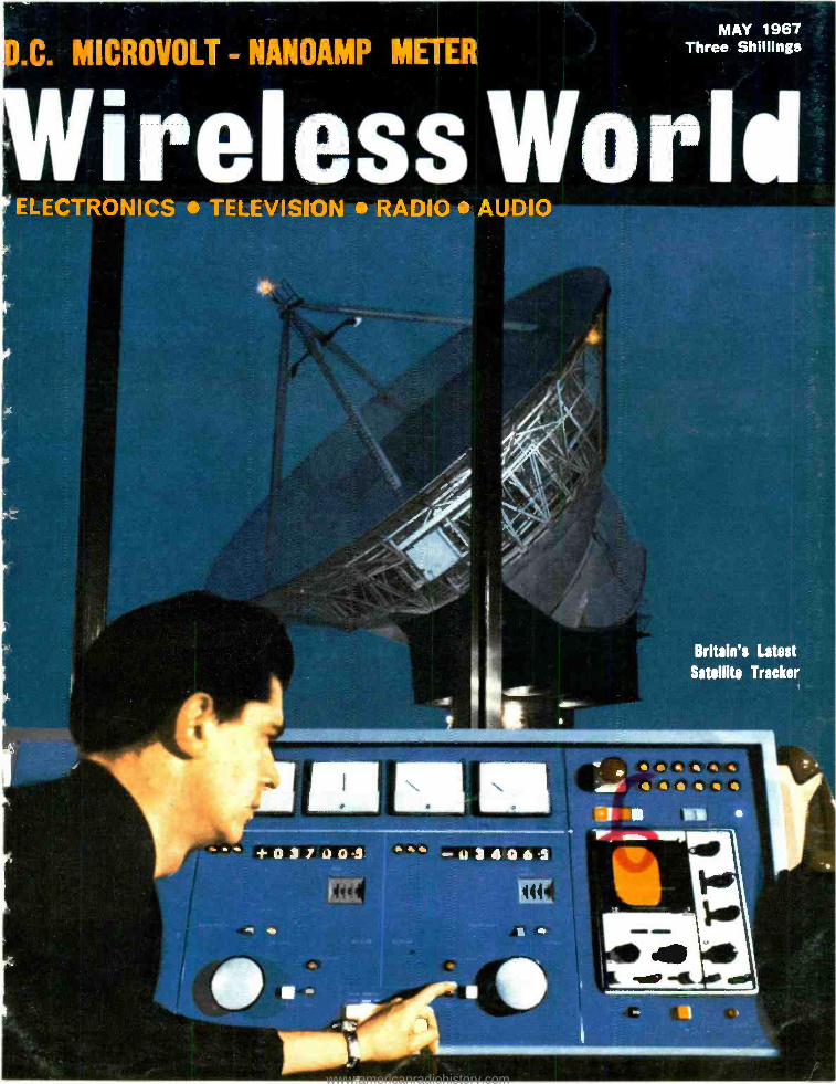
Britain's Latest
Satellite Tracker
+ó7J03 -ua4O6s
www.americanradiohistory.com
ii Wireless World
c NIACI
MAY, 1957
MEE: FOR THE BEST IN CONNECTOR DESIGN
THE SECRET IS IN
ìñß`
THE SPRING
CONNECTORS EDGE CONNECTORS -EWD SERIES LFC SERIES The latest range of Ferranti Edge Connectors offer even Ferranti LFC Connectors are designed for use either as rack greater reliability. The design incorporates a unique rolling- and panel connectors, or, when used with the appropriate leaf spring contact, which has a low rate stress limiting connector cover, as a free plug or free socket. LFC characteristic, giving controlled contact pressure and very Connectors offer: UNSURPASSED RELIABILITY VERY low insertion and withdrawal force. LOW INSERTION FORCE LOW RATE FLOATING AVAILABLE WITH 8, 16, 24, 32 or 40 POLE POSITIONS SPRING CONTROLLED CONTACT FORCE. SINGLE OR DOUBLE SIDED CONTACTS. Available in 35, 70 and 91 pole sizes.
I I s It Ii1 r
Tellir
WRAPPING TOOLS The Ferranti range of Wrapping Tools enable wrapped joints to be made quickly and easily with the minimum of staff training. Wrapped joints are the
CIRCUIT -SAVERS Ferranti Circuit- Savers overcome the
most reliable joints known, take less space and completely problem of replacing quickly and easily integrated circuits
eliminate the possibility of damage caused by heat. in printed circuit boards. The Circuit -Saver is inserted into
A full range of Hand and Power operated tools is available the board and soldered into the circuit. Integrated circuits
for making standard or miniature joints. Standard power in 8 or 10 -lead TO -5 encapsulations can then be inserted
tools are driven by compressed air and miniature power into the Circuit -Saver in a matter of seconds.Thus integrated
tools by electricity. circuits can be replaced quickly, without damage.
FERRANTI First into the Future
FERRANTI LTD KINGS CROSS ROAD DUNDEE SCOTLAND - Telephone: (ODU2) Dundee 89311
OSIT154 /2
WW -001 FOR FURTHER DETAILS
www.americanradiohistory.com
Editor- in- chiet.
W. T. COCKING, F.I.E.E.
Editor: H. W. BARNARD
Technical Editor: T. E. IVALL
Editorial: B. S. CRANK
F. MILLS
G. B. SHORTER, B.sc.
Drawing Office:
H. J. COOKE
Production:
D. R. BRAY
Advertisements:
G. BENTON ROWELL (Manager)
J. R. EYTON-JONES
Iliffe Electrical Publications Ltd., Chairman: W. E. Miller,
M.A., M. I.E. R. E. Managing Director: Kenneth Tett Dorset House, Stamford Street,
London, S.E.1
© Ilifle Electrical Publications Ltd., 1967. Permission in writing from the Editor must first be obtained before letterpress or illustrations are reproduced from this journal. Brief extracts or comments are allowed provided acknowledgement to the journal is given.
VOLUME 73 No. 5
PRICE: 3s.
FIFTY- SEVENTH YEAR OF PUBLICATION
Wireless World ELECTRONICS, TELEVISION, RADIO, AUDIO
MAY 1 967
205 The Post Office and its Powers
206 D.C. Nanoammeter and Microvoltmeter 211 Power Supply Filters and Energy Storage 214 Efficiency Considerations in a Class D Amplifier (concluded)
by G. F. Turnbull and J. M. Townsend
by D. Bollen
by L. B. Arguimbau
218 I.L.S. for Automatic Landing 221 Colour Decoding " Matrix " Circuits by T. D. Towers
236 Paris Components Show
240 Sequential Logic Design by H. R. Henly
246 Ferrite Phase Shifters, Y.I.G. Filters and Other Devices by K. E. Hancock
249 London Audio Fair Report
SHORT ITEMS
210 Chilbolton Satellite Tracking Station 220 Electronics in Medicine
231 Field Artillery Computer Equipment
235 Wire Mesh Aerial Reflectors
238 Research at Chilbolton
239 Microelectronics and Education
REGULAR FEATURES
205 Editorial Comment 233 Personalities 213 May Conferences and Ex- 235 May Meetings
hibitions 245 Books Received
219 H.F. Predictions 251 New Products
226 Literature Received 259 World of Amateur Radio 260 News from Industry
227 Letters to the Editor 262 Real and Imaginary
231 World of Wireless by " Vector "
PUBLISHED MONTHLY (3rd Monday of preceding month). Telephone: 01 -928 3333 (70 lines). Telegrams /Telex: Wiworld Iliffepres 25137 London. Cables: "Ethaworld. London, S.E.1." Annual Subscriptions: Home; £2 6s Od. Overseas; £2 15s Od. Canada and U.S.A.; $8.00. Second -Class mail privileges authorised at New York N.Y. BRANCH OFFICES: BIRMINGHAM: 401, Lynton House, Walsall Road, 22b. Telephone: Birchfields 4838. BRISTOL: 11 Marsh Street, 1. Telephone: Bristol 21491 /2. COVENTRY: 8 -10, Corporation Street. Telephone: Coventry 25210. GLASGOW: 123, Hope Street, C.2. Telephone: Central 1265 -6. MANCHESTER: 260, Deansgate, 3. Telephone: Blackfriars 4412. NEW YORK OFFICE U.S.A.: 300 East 42nd Street, New York 10017. Telephone: 867 -3900.
www.americanradiohistory.com
\Vnzr; r \V,i:1 ,
passed with honours:
After ninety -five assembly processes and
fourteen quality checks, we were beginning to
wonder if they were ever going to put us in
boxes and let us out of this place.
But we passed for performance and quality,
so we must be pretty good !
The valve for service-
It's easy to see why a Mullard valve is better.
Right from basic components it's Mullard.
They make every bit of it, under strict control.
Only in that way can they be sure that its
quality and performance are basically better.
WW-101 FOR FURTHER DETAILS EMDI`
www.americanradiohistory.com
VOL 73 NO 5
MAY 1967
WIRELESS WORLD, MAY 1967
Wireless World ELECTRONICS, TELEVISION, RADIO, AUDIO
The Post Office and its Powers WHEN the recommendations in the Government White Paper* on the reorganization of the Post Office are implemented, a new public Corporation will be set up instead of the present Government Department but it will continue to be called the Post Office. The proposed Bill will confer on the Corporation the P.M.G's existing monopoly, in a modernized form, " of telecommunications within the United Kingdom."
A single Minister (should he be called the Minister of Communications or of Tele- communications?) will be responsible for the new Corporation " and for the residue of the Postmaster General's functions (except Savings)." He will assume the P.M.G's responsibilities under the Wireless Telegraphy Act 1949 and in the broadcasting field. " This will include general regulatory control of radio transmission and reception, and the issue of licences accordingly."
We have on several occasions voiced the opinion (shared by many others) that a Department which is itself a major user of the frequency spectrum should not have the legislative responsibility for allocating frequencies. Although the new Minister will apparently have ministerial responsibility for this particular aspect of the country's telecommunications it is to be hoped the actual administration will be taken out of the hands of the Post Office and given to a new organization, similar to the Federal Communications Commission in the United States. Such a British Communications Commission could adjudicate independently on the vexed question of space in the spectrum. The present P.M.G. has, of course, his advisers in this particular field - the frequency advisory committee under the chairmanship of Dr. R. L. Smith -Rose- but one wonders whether any such non -executive body can withstand the demands of the Services for frequencies which " may be needed in an emergency."
The B.C.C. should also take over the responsibility for licences, both transmitting and receiving. (The F.C.C. wields considerable power, in that it is able to withdraw a licence if the licensee is not making full and proper use of the facility granted.) The actual collection of licence fees could be one of the " counter services " which, under the Bill, the new Post Office is to provide.
In the international field the B.C.C. would be the Government agency and at inter- national conferences would be the spokesman. Representatives of the Post Office would continue to attend, but as one of the several users of the spectrum (like the B.B.C., I.T.A., Cable & Wireless, etc.) and not as the final arbiter.
The Bill may also have repercussions in the electronics industry. At the recent dinner of the Telecommunication Engineering & Manufacturing Association the Post- master General (whose contracts, incidentally, account for a major part of the members' sales) stated that he was going to do some hard bargaining with the manu- facturers of telecommunications equipment. This reference to bargaining has taken on a new significance with the publication of the White Paper, for the proposed Bill will give the Corporation " power to manufacture anything used in connection with the exercise of its powers " and " will also have power to form subsidiaries and to engage in joint undertakings with other organizations." Might this be the first step in the direction of a nationalized telecommunications industry?
* "Reorganisation of the Post Office," Cmnd. 32'3
205
www.americanradiohistory.com
D.C. NANOAMMETER
AND MICRO-
VOLTMETER
By D. BOLLEN
Low -drift chopper -type instrument measuring
down to microvolt and nanoamp regions
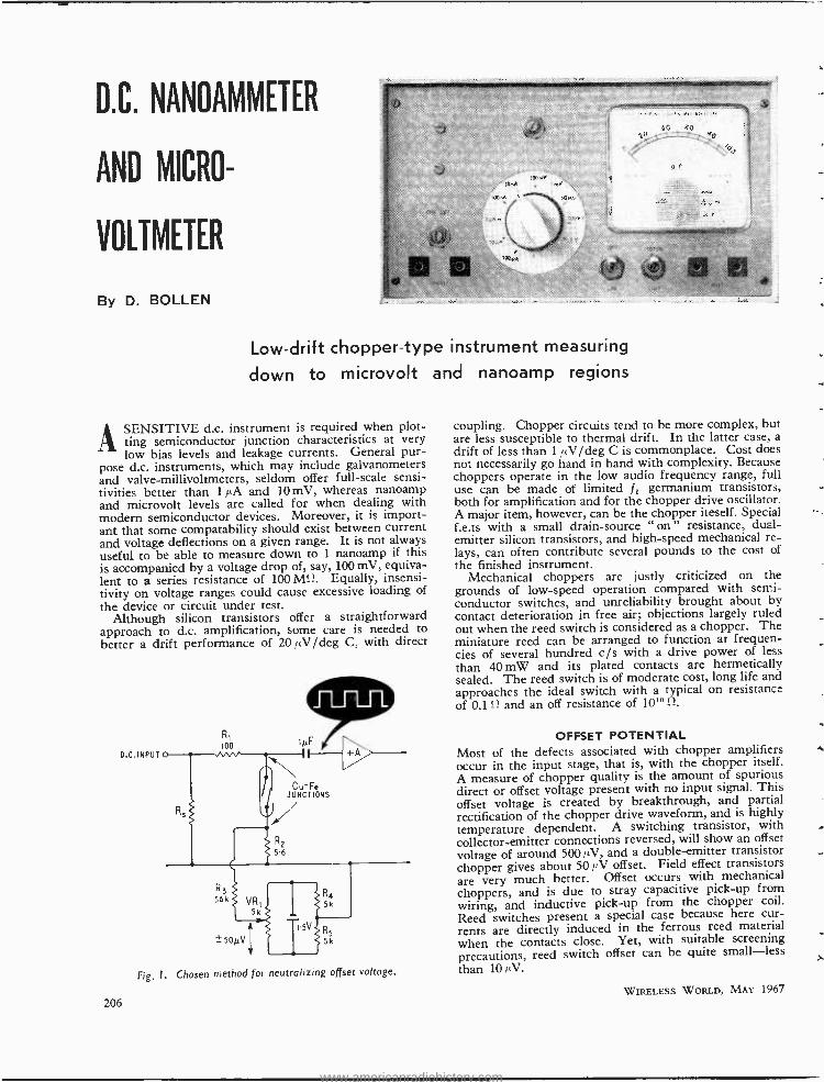
SENSITIVE d.c. instrument is required when plot- ting ting semiconductor junction characteristics at very low bias levels and leakage currents. General pur-
pose d.c. instruments, which may include galvanometers and valve -millivoltmeters, seldom offer full -scale sensi- tivities better than 1 µA and 10 mV, whereas nanoamp and microvolt levels are called for when dealing with modern semiconductor devices. Moreover, it is import- ant that some compatability should exist between current and voltage deflections on a given range. It is not always useful to be able to measure down to 1 nanoamp if this is accompanied by a voltage drop of, say, 100 mV, equiva- lent to a series resistance of 100 MQ. Equally, insensi- tivity on voltage ranges could cause excessive loading of the device or circuit under test.
Although silicon transistors offer a straightforward approach to d.c. amplification, some care is needed to better a drift performance of 20 µV /deg C, with direct
D.C. INPUT
206
loo IµF
Cu -Fe JUNCTIONS i
R3 56k
±soµV R
5k
Fig. I. Chosen method for neutralizing offset voltage.
coupling. Chopper circuits tend to be more complex, but are less susceptible to thermal drift. In the latter case, a drift of less than 1 rtV /deg C is commonplace. Cost does not necessarily go hand in hand with complexity. Because choppers operate in the low audio frequency range, full use can be made of limited f i germanium transistors, both for amplification and for the chopper drive oscillator. A major item, however, can be the chopper iteself. Special f.e.ts with a small drain -source " on " resistance, dual - emitter silicon transistors, and high -speed mechanical re- lays, can often contribute several pounds to the cost of the finished instrument.
Mechanical choppers are justly criticized on the grounds of low -speed operation compared with semi- conductor switches, and unreliability brought about by contact deterioration in free air; objections largely ruled out when the reed switch is considered as a chopper. The miniature reed can be arranged to function at frequen- cies of several hundred c/s with a drive power of less than 40 mW and its plated contacts are hermetically sealed. The reed switch is of moderate cost, long life and approaches the ideal switch with a typical on resistance of 0.1 n and an off resistance of 101° P.
OFFSET POTENTIAL Most of the defects associated with chopper amplifiers occur in the input stage, that is, with the chopper itself. A measure of chopper quality is the amount of spurious direct or offset voltage present with no input signal. This offset voltage is created by breakthrough, and partial rectification of the chopper drive waveform, and is highly temperature dependent. A switching transistor, with collector -emitter connections reversed, will show an offset
voltage of around 50014V, and a double -emitter transistor chopper gives about 501ÁV offset. Field effect transistors are very much better. Offset occurs with mechanical choppers, and is due to stray capacitive pick -up from wiring, and inductive pick -up from the chopper coil.
Reed switches present a special case because here cur- rents are directly induced in the ferrous reed material when the contacts close. Yet, with suitable screening precautions, reed switch offset can be quite small -less than 10µV.
WIRELESS WORLD, MAY 1967
www.americanradiohistory.com
Another temporary cause of voltage offset is due to temperature gradients within the instrument case, when the ambient temperature suddenly changes. Bi -metal junctions in resistors, nickel plated connectors, and switch contacts can generate a considerable current in such conditions. Fortunately, this effect is relatively short lived but is sometimes confused with normal offset currents.
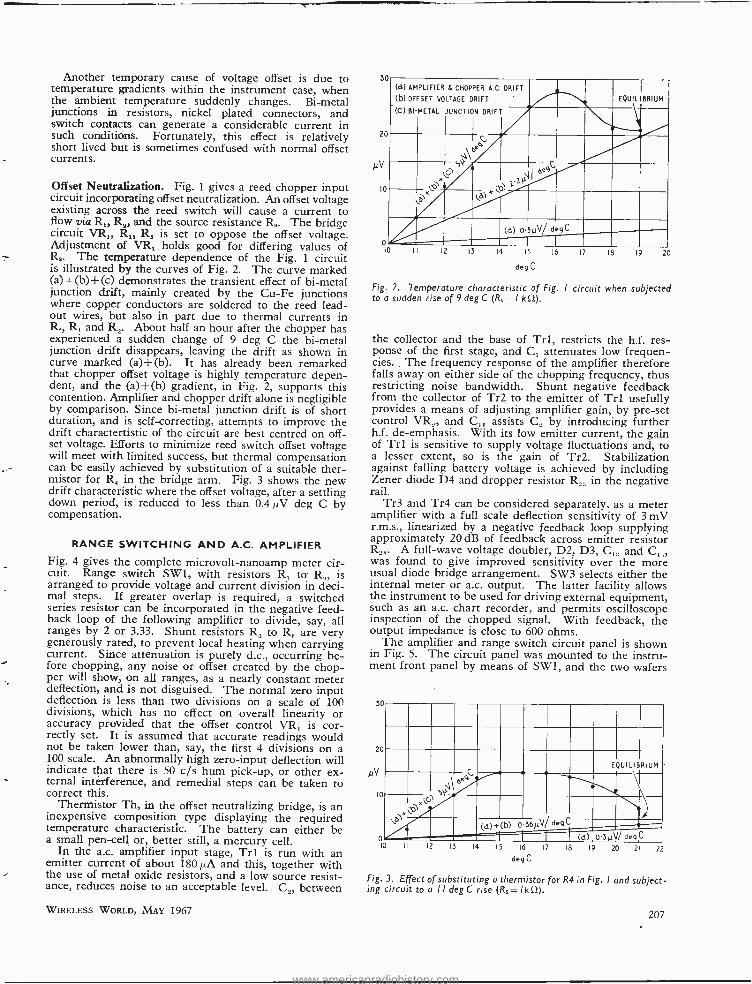
Offset Neutralization. Fig. 1 gives a reed chopper input circuit incorporating offset neutralization. An offset voltage existing across the reed switch will cause a current to flow via RI, R9, and the source resistance Rs. The bridge circuit VR RL, R, is set to oppose the offset voltage. Adjustment of VR, holds good for differing values of Rs. The temperature dependence of the Fig. 1 circuit is illustrated by the curves of Fig. 2. The curve marked (a) +(b)+(c) demonstrates the transient effect of bi -metal junction drift, mainly created by the Cu -Fe junctions where copper conductors are soldered to the reed lead - out wires, but also in part due to thermal currents in R , R, and R,. About half an hour after the chopper has experienced a sudden change of 9 deg C the bi -metal junction drift disappears, leaving the drift as shown in curve marked (a)- }-(b). It has already been remarked that chopper offset voltage is highly temperature .depen- dent, and the (a)+(b) gradient, in Fig. 2, supports this contention. Amplifier and chopper drift alone is negligible by comparison. Since bi -metal junction drift is of short duration, and is self -correcting, attempts to improve the drift charactertistic of the circuit are best centred on off- set voltage. Efforts to minimize reed switch offset voltage will meet with limited success, but thermal compensation can be easily achieved by substitution of a suitable ther- mistor for R, in the bridge arm. Fig. 3 shows the new drift characteristic where the offset voltage, after a settling down period, is reduced to less than 0.4µV deg C by compensation.
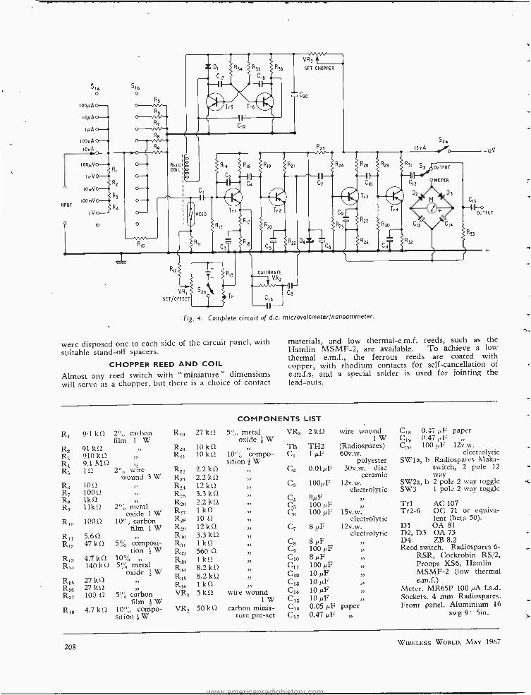
RANGE SWITCHING AND A.C. AMPLIFIER Fig. 4 gives the complete microvolt -nanoamp meter cir- cuit. Range switch SW1, with resistors R, to. R,,, is arranged to provide voltage and current division in deci- mal steps. If greater overlap is required, a switched series resistor can be incorporated in the negative feed- back loop of the following amplifier to divide, say, all ranges by 2 or 3.33. Shunt resistors R; to R, are very generously rated, to prevent local heating when carrying current. Since attenuation is purely d.c., occurring be- fore chopping, any noise or offset created by the chop- per will show, on all ranges, as a nearly constant meter deflection, and is not disguised. The normal zero input deflection is less than two divisions on a scale of 100 divisions, which has no effect on overall linearity or accuracy provided that the offset control VR, is cor- rectly set. It is assumed that accurate readings would not be taken lower than, say, the first 4 divisions on a 100 scale. An abnormally high zero -input deflection will indicate that there is 50 c/s hum pick -up, or other ex- ternal interference, and remedial steps can be taken to correct this.
Thermistor Th, in the offset neutralizing bridge, is an inexpensive composition type displaying the required temperature characteristic. The battery can either be a small pen -cell or, better still, a mercury cell.
In the a.c. amplifier input stage, Trl is run with an emitter current of about 180µA and this, together with the use of metal oxide resistors, and a low source resist- ance, reduces noise to an acceptable level. C2, between
WIRELESS WORLD, MAY 1967
30
20
pV
10
O
(d) AMPLIFIER 8 CHOPPER A.C. DRIFT
(b) OFFSET VOLTAGE DRIFT
(C) BI -METAL JUNCTION DRIFT
EQUILIBRIUM
10 12 13 14 15
deg C
16 17 18 19 20
Fig. 2. Temperature characteristic of Fig. I circuit when subjected to a sudden rise of 9 deg C (Rs-- I k 0).
the collector and the base of Trl, restricts the h.f. res- ponse of the first stage, and C, attenuates low frequen- cies. The frequency response of the amplifier therefore falls away on either side of the chopping frequency, thus restricting noise bandwidth. Shunt negative feedback from the collector of Tr2 to the emitter of Trl usefully provides a means of adjusting amplifier gain, by pre -set control VR.,, and C, assists C, by introducing further h.f. de- emphasis. With its low emitter current, the gain of Tr1 is sensitive to supply voltage fluctuations and, to a lesser extent, so is the gain of Tr2. Stabilization against falling battery voltage is achieved by including Zener diode D4 and dropper resistor R_, in the negative rail.
Tr3 and Tr4 can be considered separately, as a meter amplifier with a full scale deflection sensitivity of 3 mV r.m.s., linearized by a negative feedback loop supplying approximately 20 dB of feedback across emitter resistor R.: . A full -wave voltage doubler, D2, D3, C and C,,, was found to give improved sensitivity over the more usual diode bridge arrangement. SW3 selects either the internal meter or a.c. output. The latter facility allows the instrument to be used for driving external equipment, such as an a.c. chart recorder, and permits oscilloscope inspection of the chopped signal. With feedback, the output impedance is close to 600 ohms.
The amplifier and range switch circuit panel is shown in Fig. 5. The circuit panel was mounted to the instru- ment front panel by means of SW1, and the two wafers
3
20
µV
10
o
EQUILIBRIUM
xlGl <3
C,
ò °4 3
0.36µV / deg C (d) +(b) (d) O'3ttV/ deg C
n 12 13 14 15 16 17 18 19
deg C
20 21 22
Fig. 3. Effect of substituting a thermistor for R4 in Fig. I and subject- ing circuit to a I I deg C rise (Rs- Ikf)).
207
www.americanradiohistory.com
516 o
1000
10pA
IµA
100nA
10nA
1000/
ImV
IOmV
NPUT 100mV
1V
51b o
R5
R6 o--JM R7
o- Les.M+
Ry 15mA s2.. o--- 12V
REED COIL
1
REED
o
C15
OUTPUT
R53
R,
VR,
SET/OFFSET C16 F- Fig. 4. Complete circuit of d.c. microvoltmeter /nanoammeter.
were disposed one to each side of the circuit panel, with suitable stand -off spacers.
CHOPPER REED AND COIL Almost any reed switch with " miniature " dimensions will serve as a chopper, but there is a choice of contact
materials, and low thermal- e.m.f. reeds, such as the Hamlin MSMF -2, are available. To achieve a low thermal e.m.f., the ferrous reeds are coated with copper, with rhodium contacts for self- cancellation of e.m.f.s, and a special solder is used for jointing the lead -outs.
R1 9.1 kí2 2°;, carbon film 1 W
R, 91kS2 R3 910 kS2 R4 9.1 MO 11.5 1S2
10f2 R7 100 S2
R8 1kí2 R9 11kf2
» »
2 wire wound 3 W
,>
55
2% metal oxide 1 W
R10 100 f2 10" ,, carbon film 1 W
R11 >,
R12 47 kf2 5% composi- tion ! W
4.7 kf2 10% R14 140 kf2 5% metal
oxide } W
R13
5.6s2
R15 27 kf2 R10 27 ki) R07 100 i2
R18
» »
5% carbon film 1 W
4.7 kf2 10% compo- sition 1 W
R1 27 k S2
R_ 10 k i2
R21 10 k it
R22 R,;1
R24
2.2 k f2
2.2 kn 12 kn
R25 3.3 kf2 2.2 kf2
R27 1 kf2 R,s 10 f2
R29 12 kf2 R30 3.3 kf2 R31 lkf2
560 S2
1 kf2 8.2 8.2 kf2
R38 1 kn Viti 5 kf2
Ren
R32 R33 R34
COMPONENTS LIST
5 " metal oxide i W
>,
10% compo- sition 1 W
» » ,>
»
» ,D
f, f) J)
,>
,>
),
wire wound 1W
VR2 50 k i2 carbon minia- ture pre -set
VR3 2 kit wire wound C18 0.47 pF paper 1 W C19 0.47 pF
Th TH2 (Radiospares) C20 100 pF 12v.w. Cl 1µF 60v.w. electrolytic
polyester SW1a, b Radiospares Maka- C2 0.01µF 30v.w. disc switch, 2 pole 12
ceramic way C3 10012F 12v.w. SW2a, b 2 pole 2 way toggle
electrolytic SW3 1 pole 2 way toggle C4 8µF C5 100 pF C6 100 pF 15v.w.
electrolytic C7 8µF 12v.w.
electrolytic Cs C9 C10 C33 C12 C13 C14 C15 C36 C17
8 pF 100 pF 8 /IF 100 pF 10 pF 10 pF 10 pF 10 pF 0.05 /IF 0.47 pF
,>
» >,
13
33
33
,, paper
f)
Trl AC 107 Tr2 -6 OC 71 or equiva-
lent (beta 50). D1 OA 81 D2, D3 OA 73 D4 ZB 8.2 Reed switch. Radiospares 6-
RSR, Cockrobin RS P2,
Proops XS6, Hamlin MSMF -2 (low thermal e.m.f.)
Meter. MR65P 100 pA f.s.d. Sockets. 4 min Radiospares. Front panel. Aluminium 16
swg 9 5in.
208 WIRELESS WORLD, MAY 1967
www.americanradiohistory.com
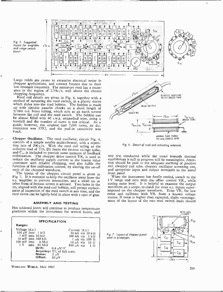
Fig. S. Suggested layout for amplifier 272 in and range switch panel.
Large reeds are prone to excessive electrical noise in chopper applications, and contact bounce due to their low resonant frequency. The miniature reed has a reson- ance in the region of 2.3 kc /s, well above the chosen chopping frequency.
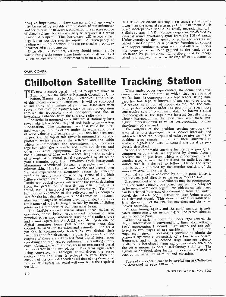
Reed coil details are given in Fig. 6, together with a method of mounting the reed switch, in a plastic sleeve which slides into the reed bobbin. The bobbin is made up with circular paxolin cheeks on a short length of 5116in o.d. brass tubing, which acts as an earth screen between the coil and the reed switch. The bobbin can be almost filled with 40 s.w.g. enamelled wire, using a handrill and the number of turns is not critical. As a guide, however, the original had 7,000 turns, its d.c. resistance was 370e, and the pull -in sensitivity was 9 mA.
Chopper Oscillator. The reed oscillator, circuit Fig. 4, consists of a simple astable multivibrator, with a repeti- tion rate of 200 c /s. With the reed coil acting as the collector load of Tr5, D1 limits the reverse voltage spike, and C is included to provide some measure of feedback stabilization. The chopper drive control VR, is used to reduce the oscillator supply current to the lowest value consistant with reliable chopping, and also fulfils the function of fine calibration control, by altering the on -off ratio of the chopped waveform.
The layout of the chopper circuit panel is given in Fig. 7. It is essential to keep the oscillator away from the a.c. amplifier to prevent interaction, and a small tin or other form of ferrous screen is advised. Two holes in the tin, aligned with the reed coil bobbin, will permit replace- ment of inspection of the reed switch at any time, and the reed sleeve can be lightly held in place with a spot of glue.
ASSEMBLY AND TESTING Hot soldered joints will continue to produce temperature gradients within the instrument for several hours, and
SPECIFICATION Ranges: Voltage (d.c.) 100 µV into 1 k S2
1 mV into 10 kû 10 mV into 100 k S2
100 mV into 1 M12 1 V into 10 M S2
Drift: 0.4 µV /°C Accuracy: 5% of full scale. Noise: 2µV Offset: 10 µV
Current (d.c.) 10 nA via 10 kn
100 nA via 1 k SZ
1µA via 100 SI 10 µA via 10Sì
100µA via 1 Ç
WIRELESS WORLD, MAY 1967
6 \ ì SLEEVING
REED SWITCH
3/4intI lA. S/lóin D- .
4-
Sla
PLASTIC SLEEVING TO FIT BRASS TUBE
I<--- l'h in 7/32 in I.D.
BRASS TUBE
APPROX 7,000 TURNS
40 s.w.g. ENAMEL WIRE
Fig. 6. Detail of reed and actuating solenoid.
any test conducted while the trend towards thermal equilibrium is still in progress will be meaningless. Atten- tion should be paid to the adequate earthing of positive rail, chopper coil tube, chopper oscillator screening can, and apropriate input and output terminals to the metal front panel.
When the instrument has finally cooled, switch to the 1 V range and zero with the offset control VR,, while noting noise level. It is helpful to examine the output waveform on a scope, to check for stray a.c. inputs super- imposed on the chopper waveform. Trim VR, for low noise and calibrate with VR, from a known voltage source. If noise is higher than expected, slight rearrange- ment of the layout of the two reed switch leads should
Fig. 7. Layout of chopper panel used in prototype. 21/ in
REED COIL LEADS
I7/8in
R36
R35
R34
209
www.americanradiohistory.com
bring an improvement. Low current and voltage ranges may be tested by suitable combinations of potentiometer and series resistor networks, connected to a precise source of direct voltage, but this will only be required if a range resistor is suspect. The instrument will accept either negative or positive polarity inputs. A discrepancy of reading when input connections are reversed will point to incorrect offset adjustment.
Once VR, has been set, zeroing should remain stable within fairly wide temperature limits, and on all switched ranges, except where the instrument is to measure current
OUR COVER
in a device or circuit ottering a resistance substantially lower than the internal resistance of the instrument. Such offset discrepancies should be small, necessitating only a slight re -trim of VR,. Voltage ranges are unaffected by external source resistance, apart from the 100µV range. Unfortunately, as the majority of plugs and sockets are nickel plated or produce a polarized junction in contact with copper conductors, some additional offset will occur of ter connectors have been gripped by the hand, or are moistened by perspiration. This effect must be recog- nized and allowed for when making offset adjustments.
Chilbolton Satellite Tracking Station T
HE new steerable aerial designed to operate down to 3 cm, built for the Science Research Council at Chil- bolton, Hampshire, by AEI Electronics, is the object
of this month's cover illustration. It will be employed to aid study of a variety of problems associated with space communication systems, such as wave propagation through the troposphere and ionosphere, and also to
investigate radiation from the sun and radio stars. The aerial is mounted on a substantial stationary base
tower which has been designed and built to an exacting specification. The maximum error that could be toler- ated was two minutes of arc under the worst conditions of wind velocity and temperature, and this has been met in practice. On top of this tower is mounted a rotatable platform which supports the reflector and the cabin which accommodates the transmitters and receivers together with the azimuth and elevation drives and other mechanical equipment. The paraboloid reflector has a diameter of 25 m and 9 m focal length and consists of a single skin central panel surrounded by 48 sector panels manufactured from two -inch thick honeycomb aluminium sandwiched between a stretch -formed alu- minium skin. This form of construction has been shown by past experience to accurately retain the reflector profile in strong gusts of wind by virtue of its high stiffness /weight ratio. When checked with an AEI Parabascan optical survey instrument the r.m.s. deviation from the paraboloid of best fit was 0.04in, this, it is
stated, can be improved upon if necessary. To allow for thermal expansion of the reflector, and to compen- sate for the fact that the gravitational forces on the panels alter with changes in reflector elevation angle, the reflec- tor is attached to its backing structure by means of sliding joints and a temperature compensating beam.
The flexible control system allows three modes of
operation, these being, programmed movement from punched paper tape, automatic tracking of a radio source and manual operation. An A.E.I. special -purpose on -line digital computer forms part of the servo loops that control the aerial in elevation and azimuth. The aerial position is continuously sensed by two digital shaft encoders (one for elevation, the other for azimuth). The cutputs of these are subtracted from digital information specifying the required co- ordinates, the resulting differ- ence information is, of course, an exact measure of aerial position error in the two planes. This error signal after being converted to analogue form, drives the servo motors until the error is reduced to zero, then the outputs of the position encoder and that of the demanded position will agree; the aerial will now be in the required position.
210
While under paper tape control, the demanded aerial co- ordinates and the time at which they are required are fed into the computer, via a tape reader, using stan- dard five hole tape, at intervals of one second or longer. To reduce the amount of input data required, the com- puter performs second order interpolation on every three consecutive sets of co- ordinate data for intervals equal to one -eighth of the tape time interval (usually 1 sec). Linear interpolation is then performed over these one- eighth intervals down to values corresponding to one- sixtyfourth of a second.
The outputs of the position sensing encoders are sampled at one -sixtyfourth of a second intervals and subtracted from the interpolated values to give the digital position error signals. These are then converted to analogue signals and used to control the aerial as pre- viously described.
When the automatic tracking facility is required, the computer error signals are replaced by signals from a receiver the output from which is proportional to the angular error between the aerial and the radio frequency source that it is desired to follow. Hence the servo loop is now completed by the angular position of the source relative to the aerial.
Manual control is achieved by simple potentiometric methods coupled directly to the servo mechanisms.
Predetermined aerial co- ordinates may be programmed on a 256 word capacity peg board, instructions being sex
in by means of " diode pegs." An address on this board can be selected by means of a command from the control panel, the " diode peg " instruction then being treated as a demand signal. This demand signal is subtracted from the output of the position encoders and the aerial moved accordingly.
Various timing signals and the aerial position is indi- cated continuously on in -line digital indicators situated in the control panel.
When the aerial is operating under tape control the digital information is converted into linear d.c. voltages, 1 mV representing 1 second of arc error, and are sub- jected to two stages of pre -amplification. In the first stage, error signal processing is provided to obtain the required dynamic characteristic of a low servo control frequency, and in the second stage transient velocity feedback is introduced from tacho- generators fitted on the servo motors to obtain satisfactory stability. The signals so obtained, after further processing, are used to control the aerial, in azimuth and elevation.
Some of the experiments to be carried out at Chilbolton are described on page 238. -Ed.
WIRELESS WORLD, MAY 1967
www.americanradiohistory.com
Power Supply Filters and Energy Storage
By L. B. ARGUIMBAU i
A New Look at Power Supply Effectiveness using Watt- second Rating in Place of Henrys and Farads
THE function of a capacitor on the input of a power supply is to accept energy in pulses and to redistri- bute it, in time, assuring a reasonably constant
voltage and power flow. Similarly the function of an input inductor is to accept energy in half sinusoids and to store it briefly, pumping a constant current into the load. Looked at in this way it would seem reasonable to study the filter action on the basis of energy storage rather than of various other quantities that may come more readily to mind but are in a sense less significant. This approach has the further advantage that it points up a number of broad design principles that should occupy an important place in our minds.
CAPACITOR -INPUT CASE Fig. 1 shows a capacitor -input power supply using RC filtering. As usual with such problems the first question we should ask ourselves is what variables to use. Con- ventional approaches to the subject use C, RF, Ede, and either RL or Ide, but these conceal the issues rather than clearing them up.
We shall assume that the desired load voltage Ede is known and also the load power. Further we shall assume that the maximum energy storage of the capacitor at its rated voltage is known, and that a given fraction, ß, of the
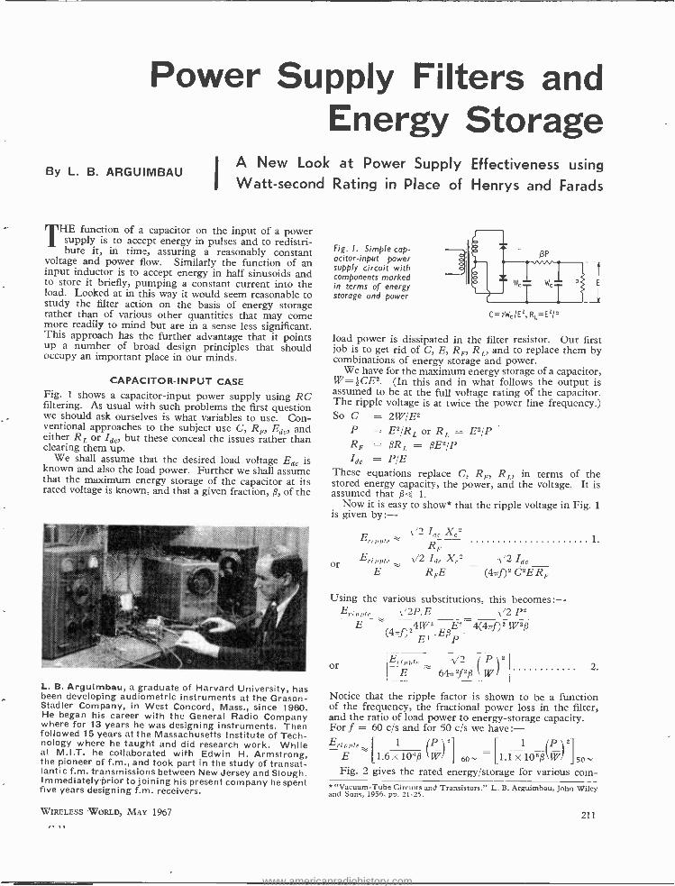
L. B. Argutmbau, a graduate of Harvard University, has been developing audiometric instruments at the Grason- Stadler Company, in West Concord, Mass., since 1960. He began his career with the General Radio Company where for 13 years he was designing instruments. Then followed 15 years at the Massachusetts Institute of Tech- nology where he taught and did research work. While at M.I.T. he collaborated with Edwin H. Armstrong, the pioneer of f.m., and took part in the study of transat- lantic f.m. transmissions between New Jersey and Slough. Immediately prior to joining his present company he spent five years designing f.m. receivers.
WIRELESS WORLD, MAY 1967
Fig. I. Simple cap- acitor -input power supply circuit with components marked in terms of energy storage and power
C=2WcIEz, R1=Ez/P
load power is dissipated in the filter resistor. Our first job is to get rid of C, E, RF, RL, and to replace them by combinations of energy storage and power.
We have for the maximum energy storage of a capacitor, W= j;CE2. (In this and in what follows the output is assumed to be at the full voltage rating of the capacitor. The ripple voltage is at twice the power line frequency.) So C = 2W /E2
P = E2IRL or RL = E2 /P RF = fRL = ßE2 /P Ide = P/E
These equations replace C, RF, RL, in terms of the stored energy capacity, the power, and the voltage. It is assumed that ß <'s 1.
Now it is easy to show* that the ripple voltage in Fig. 1 is given by:-
A/2 Ide Xe2
Eripp±e"
or Erippie A/2 Ide Xe2 E RFE
v/2 Ide
(47f)2 C2ERF
Using the various substitutions, this becomes: El pple A/2P E w "2 P2
E 4W2 E2 4(4rrf)2 Wag (47f)2 E' -.EßP
or Eri.p E
Ce. A/2 rP 64rr2f2ß \WI
1
2.
Notice that the ripple factor is shown to be a function of the frequency, the fractional power loss in the filter, and the ratio of load power to energy -storage capacity. For f = 60 c/s and for 50 c/s we have :- Erinpie 1 (P l2 1 (P 2
E 1.6 x 10⁶ß `W/ ] 6n [1.1 x 10⁸ß`W , SO- Fig. 2 gives the rated energy /storage for various corn-
* "Vacuum -Tube Circuits and Transistors." L. B. Arguimbau, John Wiley and Sons, 1956, pp. 21 -25.
211
www.americanradiohistory.com
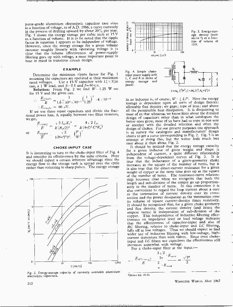
puter -grade aluminium electrolytic capacitor case sizes as a function of voltage, as of A.D. 1966, a curve currently in the process of drifting upward by about 20% per year. Fig. 3 shows the energy storage per cubic inch at 15 V as a function of volume. It is to be noted that the ripple factor in equation 1 appears to be independent of voltage. However, since the energy storage for a given volume increases roughly linearly with operating voltage it is clear that the volume effectiveness of power -supply filtering goes up with voltage, a most important point to bear in mind in transistor circuit design.
EXAMPLE
Determine the minimum ripple factor for Fig. 1
assuming the capacitors are operated at their maximum rated voltages. Use a 15 -V capacitor with 1 3in can, a 1 W load, and ß =0.1 and f =60 cis.
Solution: From Fig. 2 we find W= 1.25 W sec for 15 V and the given. can.
2 =4 <10 -8 10-' 1.25
Erippie 1
E 1.6 x 10⁶
E.ppl = 60µV. If we use three equal capacitors and divide the frac-
tional power loss, ß, equally between two filter resistors, we get,
E.;,,,,,g v 2 IdrXe3 4,2 Th.
E E(RF/2)2 - E(4nf)3C3R1'2 Or Eripple, 2 (P 1 3
E 128.73f3132. ``WI
CHOKE -INPUT CASE
It is interesting to turn to the choke -input filter of Fig. 4
and consider its effectiveness by the same criteria. Here we should expect a certain inherent advantage since the energy flow to the storage tank is spread over the cycle rather than occurring in sharp pulses. The energy storage
ioo
O
LaA
ó
O.
\` ti
"All Pr
M
ti i}MO ti Ail
a io 100
E (voLTs)
Fig. 2. Energy- storage capacity of currently available aluminium electrolytic capacitors.
212
CCCiiiCC'iiii ..ENmim.. =11111u1110unt.o MMINUNIMuI =MENEm 11111 Cí11111111111
iO
VOLUME (in')
Fig. 4. Simple choke - input power supply with L, C and R in terms of energy storage and power.
100
Fig. 3. Energy -stor- age density (watt sec/in 3) as a func- tion of volume at ISV.
L =sWL E1/P2, C= 2WCIEZ, RL =EZIP
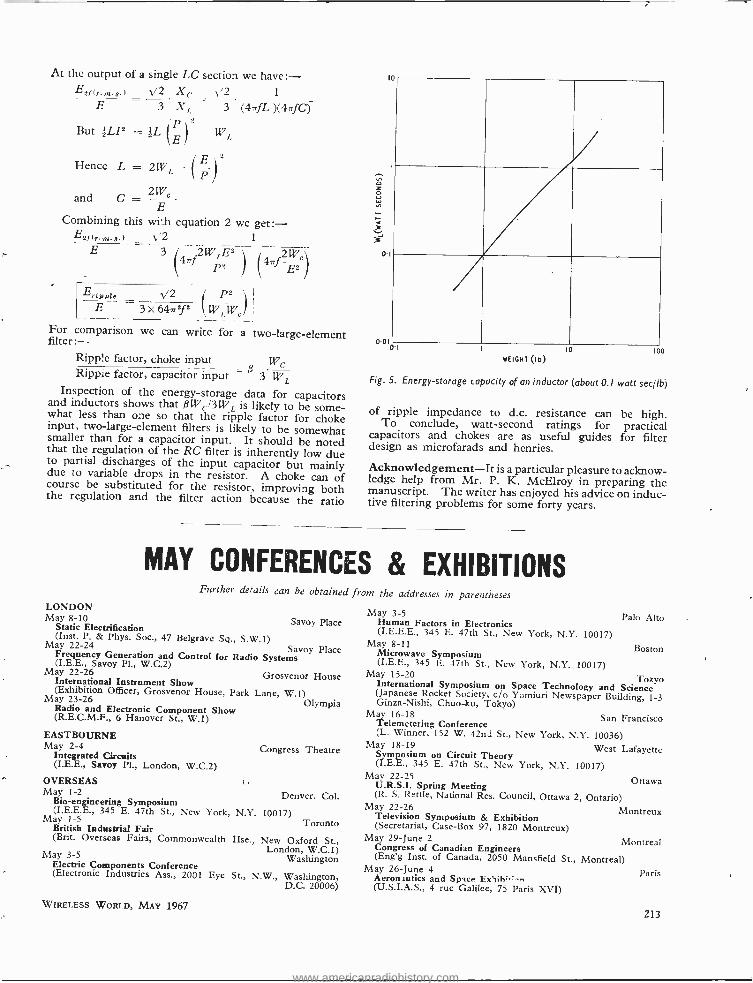
in an inductor is, of course, W = 2 LI2. Here the energy storage is dependent upon all sorts of design factors: allowable flux density; air gaps; type of iron; and above all the permissible heat dissipation. It is disquieting to most of us that wheareas we know little about the detailed design of capacitors other than in what catalogues the better ones grow, most of us have had to cope in one way or another with the detailed selection and often the design of chokes. For our present purposes one approach is to survey the catalogues and manufacturers' design sheets to get a curve corresponding to Fig. 2. Fig. 5 is an attempt at doing this, but the writer feels much less easy about it than about Fig. 2.
It should be noticed that the energy storage capacity for a given inductor of given weight and shape is
independent of current, a quite different relationship from the voltage -dependent curves of Fig. 2. It is
true that the inductance of a given -geometry choke increases as the square of the number of turns, but it is also true that the direct -current resistance for a given weight of copper at the same time goes up as the square of the number of turns. The resistance -turns relation- ship becomes clear when we recognize that both the length and sub -division of the copper go up proportion- ately to the number of turns. In this connection it is
also convenient to regard the loop current about a core as the summation of current density over its cross - section and the power dissipation as the summation over its volume of square current -density times resistivity. It should be recognized that, for a given choke geometry and flux density, the current density (and hence the ampere turns) is independent of sub -division of the copper. This independence of inductive filtering effec- tiveness on impedance level or load voltage indicates that the effectiveness of capacitor -input and also of RC filtering, relative to choke -input and LC filtering, falls off at low voltages. Thus we should expect to find wider use of inductive filtering with low- voltage, high - current transistors than with valves. Since even choke - input and LC filters use capacitors the effectiveness still increases somewhat with voltage.
For a choke -input filter at the input :- 2 2
37r ' _v_"3* Elf (r m. s') E -= 2
E"tux
"Ibidem pp. 29-31
WIRELESS WORLD, MAY 1967
www.americanradiohistory.com
At the output of a single LC section we have: - Esf V2 X c "2 1
E 3 X, 3 (47fL)(477fC)
(-3) But }LIE = ¡L
Hence L = 2W,, (P) E
2We
E Combining this wi`h equation 2 we get: -
EEf(rm.a) V2 1
E 3/ 4rrf2WPEE
1 \4,7 É el
and
Erippte 1/2 E
E 3x64nsfE (WiWe)
For comparison we can write for a two -large -element filter :- Ripple factor, choke input We Ripple factor, capacitor input = ß
3 W Inspection of the energy- storage data for capacitors
and inductors shows that $W(;13WL is likely to be some- what less than one so that the ripple factor for choke input, two -large -element filters is likely to be somewhat smaller than for a capacitor input. It should be noted that the regulation of the RC filter is inherently low due to partial discharges of the input capacitor but mainly due to variable drops in the resistor. A choke can of course be substituted for the resistor, improving both the regulation and the filter action because the ratio
lo
00l0.1 10 loo
WEIGHT (lb)
Fig. 5. Energy- storage capacity of an inductor (about 0.1 watt sec /lb)
of ripple impedance to d.c. resistance can be high. To conclude, watt- second ratings for practical
capacitors and chokes are as useful guides for filter design as microfarads and henries.
Acknowledgement -It is a particular pleasure to acknow- ledge help from Mr. P. K. McElroy in preparing the manuscript. The writer has enjoyed his advice on induc- tive filtering problems for some forty years.
MAY CONFERENCES & EXHIBITIONS Further derails can be obtained
LONDON May 8 -10 Savoy Place Static Electrification
(Inst. P. & Phys. Soc., 47 Belgrave Sq., S.W.1) May 22 -24 Savoy Place Frequency Generation and Control for Radio Systems (I.E.E., Savoy Pl., W.C.2) May 22 -26 Grosvenor House International Instrument Show
(Exhibition Officer, Grosvenor House, Park Lane, W.1) May 23 -26 Radio and Electronic Component Show
Olympia (R.E.C.M.F., 6 Hanover St., W.1)
EASTBOURNE May 2-4 Congress Theatre Integrated Circuits
(I.E.E., Savoy Pl., London, W.C.2)
OVERSEAS May 1 -2 Denver, Col. Bio- engineering Symposium
(I.E.E.E., 345 E. 47th St., New York, N.Y. 10017) May 1 -5 Toronto British Industrial Fair (Brit. Overseas Fairs, Commonwealth Hse., New Oxford St.,
London, W.C.1) May 3 -5 Washington Electric Components Conference (Electronic Industries Ass., 2001 Eye St., N.W., Washington,
D.C. 20006)
WIRELESS WORLD, MAY 1967
from the addresses in parentheses
May 3 -5 Palo Alto Human Factors in Electronics (I.E.E.E., 345 E. 47th St., New York, N.Y. 10017)
May 8-11 Boston Microwave Symposium (I.E.E., 345 E. 47th St., New York, N.Y. 10017)
May 15 -20 Tokyo International Symposium on Space Technology and Science (Japanese Rocket Society, c/o Yomiuri Newspaper Building, 1 -3 Ginza -Nishi, Chuo -ku, Tokyo) May 16 -18 San Francisco Telemetering Conference
(L. Winner, 152 W. 42nd St., New York, N.Y. 10036) May 18 -19 West Lafayette Symposium on Circuit Theory
(I.E.E., 345 E. 47th St., New York, N.Y. 10017) May 22 -25 Ottawa U.R.S.I. Spring Meeting
(R. S. Rettie, National Res. Council, Ottawa 2, Ontario) May 22 -26 Montreux Television Symposium & Exhibition
(Secretariat, Case -Box 97, 1820 Montreux) May 29 -June 2 Montreal Congress of Canadian Engineers
(Eng'g Inst. of Canada, 2050 Mansfield St., Montreal) May 26 -June 4 Paris Aeronautics and Space ExSiht.: -.,
(U.S.I.A.S., 4 rue Galilee, 75 Paris XVI)
213
www.americanradiohistory.com
Efficiency Considerations in a
Class D Amplifier IMPROVED 5 W DESIGN
BY G. F. TURNBULL, M.Sc. AND J. M. TOWNSEND, M.Sc.
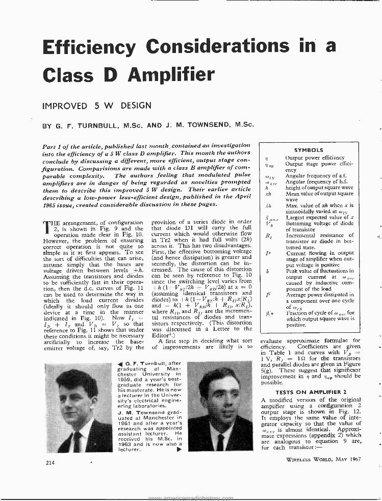
Part 1 of the article, published last month, contained an investigation into the efficiency of a 5 W class D amplifier. This month the authors conclude by discussing a different, more efficient, output stage con- figuration. Comparisions are made with a class B amplifier of com- parable complexity. The authors feeling that modulated pulse amplifiers are in danger of being regarded as novelties prompted them to describe this improved 5 W design. Their earlier article describing a low -power less-efficient design, published in the April 1965 issue, created considerable discussion in these pages.
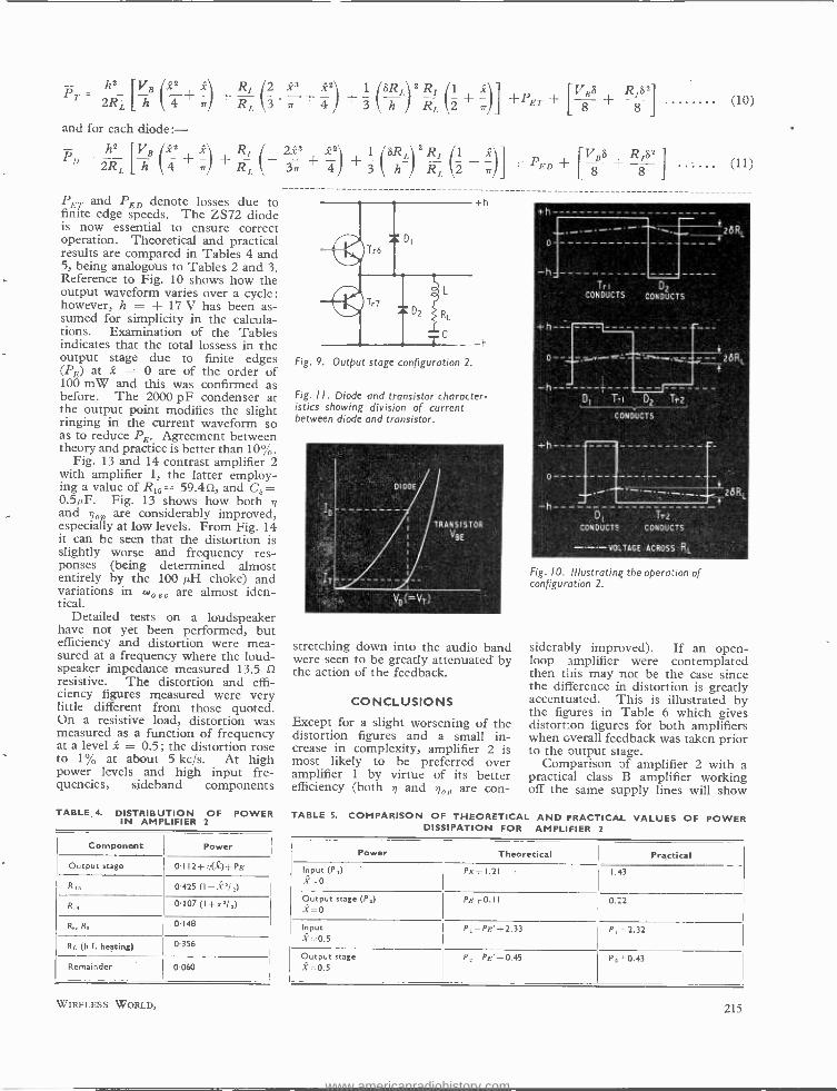
THE arrangement, of configuration 2, is shown in Fig. 9 and the operation made clear in Fig. 10.
However, the problem of ensuring correct operation is not quite so simple as it at first appears. To see the sort of difficulties that can arise, assume simply that the bases are voltage driven between levels +h. Assuming the transistors and diodes to be sufficiently fast in their opera- tion, then the d.c. curves of Fig. 11
can be used to determine the way in which the load current divides (ideally it should only flow in one device at a time in the manner indicated in Fig. 10). Now It = I { IT and V = V7 so that reference to Fig. 11 shows that under these conditions it might be necessary artificially to increase the base - emitter voltage of, say, Tr2 by the
214
provision of a series diode in order that diode D1 will carry the full current which would otherwise flow in Tr2 when it had full volts (2h) across it. This has two disadvantages. First, the effective bottoming voltage (and hence dissipation) is greater and secondly, the distortion can be in- creased. The cause of this distortion can be seen by reference to Fig. 10 since the switching level varies from +h (1 - VBr'2h + VBD /2h) at x = 0 (assuming identical transistors and diodes) to +h (1 -VBT /h + R77x, /R,) and - h(1 + VB /h + R, x/R1), where R, and RIT are the incremen- tal resistances of diodes and tran- sistors respectively. (This distortion was discussed in a Letter to the Editors.)
A first step in deciding what sort of improvements are likely is to
Q. F. Turnbull, after graduating at Man- chester University in 1959, did a year's post- graduate research for his masterate. He is now a lecturer in the Univer- sity's electrical engine- ering laboratories. J. M. Townsend grad- uated at Manchester in 1961 and after a year's research was appointed assistant lecturer. He received his M.Sc. in 1963 and is now also a lecturer.
7
op
WIN W ose h xh
zh
Xntl:r VB
R1
I+
S
P
ß/,r
SYMBOLS Output power efficiency Output stage power effici- ency Angular frequency of a.f. Angular frequency of h.f. height of output square wave Mean value of output square wave Max. value of xh when x is sinusoidally varied at WIl Largest expected value of x Bottoming voltage of diode of transistor Incremental resistance of transistor or diode in bot- tomed state. Current flowing in output stage of amplifier when out- put voltage is positive Peak value of fluctuations in output current at W
caused by inductive com- ponent of the load Average power dissipated in a component over one cycle of to,N Fraction of cycle of W o., e for which output square wave is positive.
evaluate approximate formulae for efficiency. Coefficients are given in Table 1 and curves with VB = 1 V, R1 = 1 Sl for the transistors and parallel diodes are given in Figure 5(g). These suggest that significant improvement in +7 and +lop should be possible.
TESTS ON AMPLIFIER 2
A modified version of the original amplifier using a configuration 2 output stage is shown in Fig. 12. It employs the same value of inte- grator capacity so that the value of coo ,. e is almost identical. Approxi- mate expressions (appendix 2) which are analogous to equation 9 are, for each transistor:-
WIRELESS WORLD, MAY 1967
www.americanradiohistory.com
P' 2R¿[hB4+/ +R \2 X32) 1 zRL R 3' R ,r 4 3 h
and for each diode: h2 VB
(X2 xl R (_ 2x3 2 1 1 z V a `+ / + + 4) + 3
(8RL'2RI h Rc 2 ), ED [ 8 +
1 21 1 +PET + [V8 B8 - R8 f
PET. and PED denote losses due to finite edge speeds. The ZS72 diode is now essential to ensure correct operation. Theoretical and practical results are compared in Tables 4 and 5, being analogous to Tables 2 and 3. Reference to Fig. 10 shows how the output waveform varies over a cycle: however, h = + 17 V has been as- sumed for simplicity in the calcula- tions. Examination of the Tables indicates that the total lossess in the output stage due to finite edges (PE) at z = 0 are of the order of 100 mW and this was confirmed as before. The 2000 pF condenser at the output point modifies the slight ringing in the current waveform so as to reduce PE. Agreement between theory and practice is better than 10%.
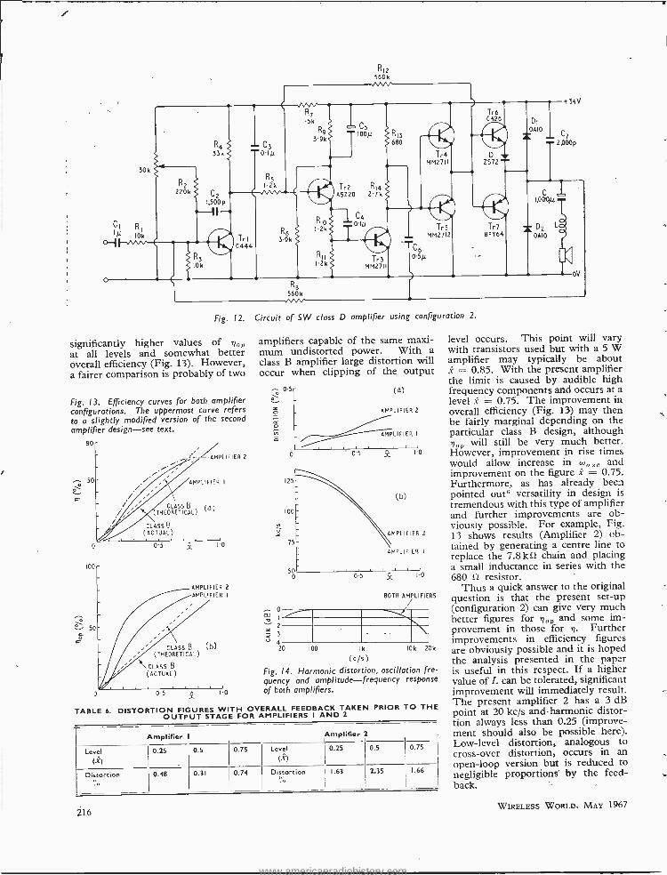
Fig. 13 and 14 contrast amplifier 2 with amplifier 1, the latter employ-. ing a value of R15 = 59.451, and C8= 0.5µF. Fig. 13 shows how both ij and *lo are considerably improved, especially at low levels. From Fig. 14 it can be seen that the distortion is slightly worse and frequency res- ponses (being determined almost entirely by the 100 µH choke) and variations in (sosa are almost iden- tical.
Detailed tests on a loudspeaker have not yet been performed, but efficiency and distortion were mea- sured at a frequency where the loud- speaker impedance measured 13.5 S)
resistive. The distortion and effi- ciency figures measured were very little different from those quoted. On a resistive load, distortion was measured as a function of frequency at a level x = 0.5; the distortion rose to 1% at about 5 kc /s. At high power levels and high input fre- quencies, sideband components
TABLE 4. DISTRIBUTION OF POWER IN AMPLIFIER 2
Component Power
Output stage 0. 112+ n(-Z)-i- Pa
R,, 0.425 (I- .X'/ _)
R 0.107 (I +x' /,)
R,, R, 0. 148
RL (h f. heating) 0356
Remainder 0.060
WIRELESS WORLD,
Fig. 9. Output stage configuration 2.
Fig. II. Diode and transistor character- istics showing division of current between diode and transistor.
stretching down into the audio band were seen to be greatly attenuated by the action of the feedback.
CONCLUSIONS
Except for a slight worsening of the distortion figures and a small in- crease in complexity, amplifier 2 is most likely to be preferred over amplifier 1 by virtue of its better efficiency (both +i and iioP are con-
(10)
+h
TrI CONDUCTS
D2
CONDUCTS
h -
+h
tzáRL
DI Ti D2 Tr2
CONDUCTS
o-
h Di
CONDUCTS
Tr2 CONDUCTS
- - - VO_TAGE ACROSS RL
Fig. 10. Illustrating the operation of configuration 2.
siderably improved). If an open - loop amplifier were contemplated then this may not be the case since the difference in distortion is greatly accentuated. This is illustrated by the figures in Table 6 which gives distortion figures for both amplifiers when overall feedback was taken prior to the output stage.
Comparison of amplifier 2 with a practical class B amplifier working off the same supply lines will show
TABLE 5. COMPARISON OF THEORETICAL AND PRACTICAL VALUES OF POWER DISSIPATION FOR AMPLIFIER 2
Power Theoretical Practical Input (P,)
-0 PE 1.21 1.43
Output stage (P,) x =0
PurO.II 0.22
Input x =0.5
P,+Pa'+2.33
Output stage 1-0.5
P,+Pe+0.45
215
www.americanradiohistory.com
30k
R1
10k
R2
220k
R4 33k
R7 5k
C3
R9 3.9k
R12 560k
yVV
0Iµ
R5 I2k
C2
C5 T!OOp R13
600
Tr2 R14 ASZ20 2.7k
Tra MM2711
Tr6 C426
1,500 p
Tri C444
R6 3.9k
R10 I.2k
C4 0Ip
R3 ICk
R8 560k WV
R11 I.2k Tr3
MM27I1
C6 0.5p
Try MM2712
D ZS72 =
Tr7 BF 064
1,4i
DI
0010
T 2,0006
C'I 1,000/1
L
oV
i 02 GAIO
Fig. 12. Circuit of SW class D amplifier using configuration 2.
significantly higher values of 'qo at all levels and somewhat better overall efficiency (Fig. 13). However, a fairer comparison is probably of two
Fig. 13. Efficiency curves for both amplifier configurations. The uppermost curve refers to a slightly modified version of the second
amplifier design -see text.
a
80
50
100
¿PLIFIER 2
AMPLIFIER I
CLASS B ( d
) THEORETICAL)
CLASS B
(ACTUAL)
0.5 o
AMPLIFIER 2
AMPLIFIER I
TABLE 6.
CLASS B (b) (THEORETICAL) \ CLASS B
(ACTUAL)
0.5 X 10
DISTORTION FIGURES WITH OVERALL FEEDBACK TAKEN PRIOR TO THE OUTPUT STAGE FOR AMPLIFIERS I AND 2
amplifiers capable of the same maxi- mum undistorted power. With a class B amplifier large distortion will occur when clipping of the output
-- 03 á o
Ñ
o
I
2
< 3
4 20
(d)
AMPLIFIER 2
AMPLIFIER I
o
125
100
75
500
0.5 X 1.0
0.5
(b)
AMPLIFIER 2
AMPLIFIER I
X I!o
BOTH AMPLIFIERS
100 Ik
(c /s) Fig. 14. Harmonic distortion, oscillation fre- quency and amplitude -frequency response
of both amplifiers.
10k 20k
Amplifier Amplifier 2
Level
(-X)
0.25 0.5 0.75 Level (X)
0.25 0.5 0.75
Distortion ,ó
0.48 0.31 0.74 Distortion 1.63 2.35 1.66
216
level occurs. This point will vary with transistors used but with a 5 W amplifier may typically be about X = 0.85. With the present amplifier the limit is caused by audible high frequency components acrd occurs at a level X = 0.75. The improvement in overall efficiency (Fig. 13) may then be fairly marginal depending on the particular class B design, although tno will still be very much better. However, improvement in rise times would allow increase in too and improvement on the figure X = 0.75. Furthermore, as has already been pointed outs versatility in design is tremendous with this type of amplifier and further improvements are ob- viously possible. For example, Fig. 13 shows results (Amplifier 2) ob- tained by generating a centre line to replace the 7.8 k chain and placing a small inductance in series with the 680 û resistor.
Thus a quick answer to the original question is that the present set -up (configuration 2) can give very much better figures for '9o and some im- provement in those for +l. Further improvements in efficiency figures are obviously possible and it is hoped the analysis presented in the paper is useful in this respect. If a higher value of L can be tolerated, significant improvement will immediately result. The present amplifier 2 has a 3 dB point at 20 kc /s and harmonic distor- tion always less than 0.25 (improve- ment should also be possible here). Low -level distortion, analogous to cross -over distortion, occurs in an open -loop version but is reduced to negligible proportions by the feed- back.
WIRELESS WORLD, MAY 1967
www.americanradiohistory.com
At this point the Editor's past remarks' seem extremely relevant when one considers the exact signi- ficance of efficiency figures. Consider amplifier 2 with the small choke in series with the 680 fl resistor. At any level of output, no resistor dis- sipates more than 150 mW. A maximum of 1 /3W is dissipated in the loudspeaker depending on the size of L (> 100 RH). Under normal operation heating will only be equi- valent to, say, z = 0.1 giving a maxi- mum of 265 mW total in the output stage (with L = 100 pH). Maximum can temperature of the BFY64 is about 12 deg C above ambient. At full load, the only significant in- crease in power loss is in the output stage with the total power now at 1.3 W (BFY64 temperature 43 deg C above ambient).
To merit further improvements one is surely thinking in terms of microminiaturization, since even with the present arrangement all com- ponents operate at all times well below maximum ratings. Considerations of this sort have possibly more relevance in other fields.
REFERENCES
5. B. D. Josephson, Letter to the Editor, Wireless World, July, 1965.
6. F. Butler, Letter to the Editor, Wireless World, July, 1965.
7. Wireless World, April, 1965, p. 154.
APPENDIX I
Calculation of Efficiency in Case (ii), Table I
wo,L <<R: R1= oo
Voltage and current waveforms are iden- tical, being rectangular waves of height
h, ! h /RL respectively. Correct oper- ation is always ensured, i.e. Trl carries the current I + =h /Rt.
The voltage across the transistor is V- VR -1 -R,I so that the power (Pr) averaged over one cycle of the oscil- lation frequency is given by:-
VR.h R1.h2 2ß P. RL F Re J 27r
h2 Vg RI - - x
2RL h R1
Now wmN> wo sc so that substituting x -x sin went and integrating over one cycle of the input signal gives the average power ("TO:-
Pr h VI? RI
2Ri:L h Ri.
The load power (P) at a point in a cycle of the input signal is P= L2x2 /RL
WIRELESS WORLD, MAY 1967
DESIGN
In designing a modulated pulse amplifier of the feedback type (whichever configuration of the output stage is to be used) one important factor in minimizing distortion is to ensure that the loop gain is both large and as linear as possible. Although one part of the loop in the feedback circuit is a hysteretic relay it can be shown both theoretically and practically (e.g. Fig. 7a, ref. 1) that the relay has a continuous characteristic as far as the low (audio) modulating frequency is concerned. In view of the original requirement of high loop gain it is therefore essential that the gain of this low frequency characteristic is high. This is achieved first by keeping the hysteresis small and secondly by keeping all stray capacitance with- in the loop as small as possible as it is found that additional time constants comparable in size with the main loop time constant in the first stage have a profound effect on loop gain and distortion. This means that the layout should be small and neat.
RECAP
The first stage, the summing integrator, must be designed so that the input impedance does not cause too great a decrease in the loop gain since this resist- ance, together with the feedback resistance and all the other resist- ances connected to the base point form a complex attenuator net- work within the feedback loop. The principal requirement is a transistor having a good high fre- quency response together with a high gain at low currents.
The second requirement for keeping the distortion low is a linear loop gain. The first stage provides some of this gain but the largest part is provided by the relay in the way described earlier. In order to maintain linearity the circuit was arranged so that its switching character- istics between the two states were reasonably similar while retain- ing simple circuitry. This is the reason for employing a comple- mentary driver stage in addition to a complementary output stage.
Further design details are given in ref. 1.
and thus the heating losses in R1 are: - h2(1 -x2)
PiRI.= RL
Averaging over one cycle of the input waveform gives:- - h2 h2(2 -z')
P= - . and P, = L L
P Thus ,i =, -- -
P +PRL +2P7
i.e.
i.e.
APPENDIX 2
Derivation of Equations 10 and 11
In the amplifier 2 at x = 0, the " change- over points " are approximately 0, 42, n, 3x/2, etc. It is thus very easy to show that expressions for P.1 and PD are identical,
VRS R1S2
Pl = - 8 +
12
Conduction is by one diode and tran- sistor once 'xI > SR, /h which with L- 100 µH is approximately for Ix'> L
VR h2 R, h'-' R,2 Then P. =
h 2R x(x -I
1) T R 2R x(x + 1) -i
6 (1 + x)
!. I. I.
VR h2 R h' R'-, and P =
h 2R X(1 -X) + R 2R
x(1-x) + 6'
(1-x) r , t.
'1 =
P + 2Pr
,c2
non
( ll 2+2 [ h
i
R¡J
The approximate formulae of equa- tions 10 and 11 have been derived first by assuming that this expression is valid for all x (i.e. changeover to the other diode and transistor occurs at x - 0 as it does with a large value of L) and aver- aging: since this gives a value at x =0 which is much less than P,, this has been simply added to the result. Exact analysis is readily achieved but leads to rather weighty expressions, and anyway the approximate method gives little error at large values of x, e.g. x = 0.5.
217
www.americanradiohistory.com
I.L.S. for Automatic Landing Can the system be improved?
T a time when automatic landing is about to go into regular service on British airlines it is disquieting to hear that I.L.S. (Instrument Landing System), on
which the whole process depends, has " inherent defects" and that " the required system integrity cannot be guaranteed." The words quoted were used by two experts from the Royal Aircraft Establishment, J. Ben- jamin and J. M. Jones, in papers presented at a joint I.E.E. /I.E.R.E. conference on " Air Traffic Control Systems Engineering and Design " held in London in March. Their argument was not that the reliability and accuracy of the manufactured equipment were in ques- tion but that the "integrity" of the whole operating system -that is, including the radio propagation path- was not good enough for automatic landing. " Integrity" is, in fact, a measure of system reliability, and in the case of I.L.S. it is given by the probability value that a radio signal in space of specified characteristics is avail- able to the landing aircraft.
R.A.E. have carried out a feasibility study to determine the suitability of I.L.S. as the sole means of guidance for automatic landing, and the results were presented in a paper written by J. M. Jones. It emerged from this that the " locali er " transmitter, which provides field patterns for guidance in azimuth, is the most critical part of the system -the glide -path transmitter not being used during
0.5µsec PULSES ON f1
J L
(a)
MICROWAVE TRANSMITTER I
PART OF HYPERBOLIC PHASE PATTERN
RUNWAY - - ---- - -. ---
I µsec PULSES ON f2
MICROWAVE
fl 1
±90/5
+i56
C.C.C. OF fl n2±90 PULSES
(b)
TRANSMITTER 2
C.C.COEFF. OF
fl /f2 PULSES
TIME DISPLACEMENT -IA- BETWEEN PULSEST)
TIME DISPLACEMENT (T) OR AIRCRAFT POSITION
C.C.C. OF fl /f2 ±150 PULSES
} DIFFERENCE + VALUE
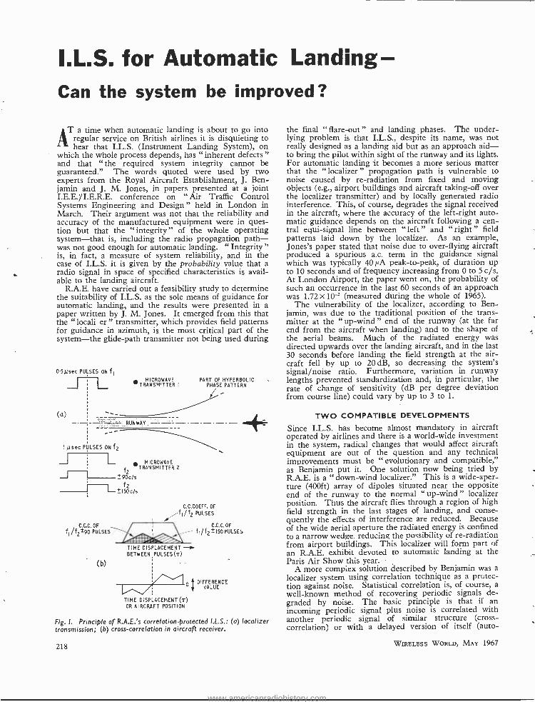
Fig. I. Principle of R.A.E.'s correlation- protected I.L.S.: (a) localizer transmission; (6) cross -correlation in aircraft receiver.
218
the final " flare -out " and landing phases. The under- lying problem is that I.L.S., despite its name, was not really designed as a landing aid but as an approach aid - to bring the pilot within sight of the runway and its lights. For automatic landing it becomes a more serious matter that the "localizes" propagation path is vulnerable to noise caused by re- radiation from fixed and moving objects (e.g., airport buildings and aircraft taking -off over the localizer transmitter) and by locally generated radio interference. This, of course, degrades the signal received in the aircraft, where the accuracy of the left -right auto- matic guidance depends on the aircraft following a cen- tral equi- signal line between "left" and "right" field patterns laid down by the localizer. As an example, Jones's paper stated that noise due to over -flying aircraft produced a spurious a.c. term in the guidance signal which was typically 40µA peak -to-peak, of duration up to 10 seconds and of frequency increasing from 0 to 5 c /s. At London Airport, the paper went on, the probability of such an occurrence in the last 60 seconds of an approach was 1.72 X 10' (measured during the whole of 1965).
The vulnerability of the localizer, according to Ben- jamin, was due to the traditional position of the trans- mitter at the "up- wind" end of the runway (at the far end from the aircraft when landing) and to the shape of the aerial beams. Much of the radiated energy was directed upwards over the landing aircraft, and in the last 30 seconds before landing the field strength at the air- craft fell by up to 20 dB, so decreasing the system's signal /noise ratio. Furthermore, variation in runway lengths prevented standardization and, in particular, the rate of change of sensitivity (dB per degree deviation from course line) could vary by up to 3 to 1.
TWO COMPATIBLE DEVELOPMENTS
Since I.L.S. has become almost mandatory in aircraft operated by airlines and there is a world -wide investment in the system, radical changes that would affect aircraft equipment are out of the question and any technical improvements must be " evolutionary and compatible," as Benjamin put it. One solution now being tried by R.A.E. is a " down -wind localizer." This is a wide -aper- ture (400ft) array of dipoles situated near the opposite end of the runway to the normal " up -wind " localizer position. Thus the aircraft flies through a region of high field strength in the last stages of landing, and conse- quently the effects of interference are reduced. Because of the wide aerial aperture the radiated energy is confined to a narrow wedge. reducing the possibility of re- radiation from airport buildings. This localizer will form part of an R.A.E. exhibit devoted to automatic landing at the Paris Air Show this year.
A more complex solution described by Benjamin was a localizer system using correlation technique as a protec- tion against noise. Statistical correlation is, of course, a well -known method of recovering periodic signals de- graded by noise. The basic principle is that if an incoming periodic signal plus noise is correlated with another periodic signal of similar structure (cross - correlation) or with a delayed version of itself (auto-
WIRELESS WORLD, MAY 1967
www.americanradiohistory.com
correlation), there is high correlation between the periodic components but practically zero correlation between the random noise and the periodic components and between the noise and itself. In a practical system, the noise is, in effect, "cancelled out."
The R.A.E. " Correlation Protected I.L.S." uses two microwave transmitters straddling the runway at its mid- point, as shown at (a) in Fig. 1. Their frequencies, f, and f, are arranged such that the difference frequency, f, -f.,, is a normal v.h.f. localizes- frequency, so that, although the aircraft has to have a small horn microwave aerial (with a built -in mixer), its I.L.S. receiver does not have to be modified. Transmission f, is modulated with 0.5 µs pulses and f._ with synchronized 1µs pulses, both at a p.r.f. of 200 kc /s. In addition 1, carries the normal 90 c/s and 150 c/s tone modulations used in I.L.S. to identify the "left" and "right" field patterns, but here only the sidebands are selected and the microwave fre- quencies actually transmitted are f,±90 c/s and 12±150 c /s. These two frequencies are also pulse modulated and, as shown, the pulses are advanced and delayed by 0.25 /4s with respect to the Transmitter 1 pulse.
The effect of these transmissions is to set up three hyperbolic phase patterns in space. These delineate the phase relationships at points in space of the pairs of pulses carried by f, /fp, f1/12±90c /s and 11122 ±150c /s. The hyperbolic patterns can be considered as being made up of lines (as shown), each of which joins all points in
My. 40
30
20
15
10
e
6
5
4
MONTREAL
space where a pair of pulses arrive with a given time displacement (-) between them. As the landing aircraft deviates from the runway centre line its horn aerial " samples " these lines. The I.L.S. receiver acts as the integrating filter of a correlation detector, and at each point in space the receiver effectively computes the cross - correlation coefficient between each pair of pulses. Ii the aircraft moved laterally across the pattern lines, thus " seeing " a series of different time displacements (r) between pulse pairs, the receiver would derive three cross -correlation functions as shown at (b). From the three cross -correlation coefficients at any point (value of r), the receiver automatically derives a d.c. voltage cor- responding to that giving the difference between the "left " and " right " modulated signals in conventional I.L.S., and this voltage is used for control of the steering. This d.c. difference value at any point in space is, in fact, the difference between the 111,± 90 and f,/f±150 c.c. coefficients, divided by the f,/f, c.c. coefficient, and a graph of this difference value with r is shown at (b).
The great advantage of the system is that the difference value derived in the aircraft's I.L.S. receiver and used for steering is a measure of time difference instead of signal - amplitude difference, so that it is independent of trans- mission amplitudes and is unaffected by uncorrelated noise in the radio propagation path.
A similar technique is used to form the glide -path component of the C.P.I.L.S. scheme.
H. F. PREDICTIONS - MAY
..........
MVAMI Aim .) I J -_ _,_,-I__--_- !!!lZliWINMI lr NIP CAI !!!!!NMl.a.111 alerll%!!!!rle !601r !!E!
1.1..M.111111111MMM. .1111111111111.....110111
WITH AURORAL CORRECTION
12 16 20
Mc/. 40
Nr
I t 0 4
Me/. 40
30
JOHANNESBURG ............ 20
I5 :: :. ¡R IO ==::A1111/,1111 >.MI!!
e8l4!!!!!eV!le881 !!! e
6
s
4
UM= !!II!!!!!n1!!! !WI9!!!!!i!!! =1111111111111111=1111111MMIC
3 .......
e i2
HONG KONG
16 20
30
20
5
IO
e
6
s
4
03
Mc/r 40
J
J
12 16 20 0 0 4 6 12 16
G. M.T. G. M.T.
WIRELESS WORLD, MAY 1967
20
MEDIAN STANDARD M U F
OPTIMUM TRAFFIC FREQUENCY
- . - -- LOWEST USABLE H F
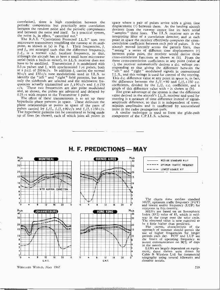
The charts show median standard MUF, optimum traffic frequency (FOT) and lowest usable frequency (LUF) for reception in this country.
MUFs are based on an Ionospheric Index (IF2) value of 83, which is mid -
30 way in the range over the solar cycle. The observed value is now expected to
20 be a little higher than predicted. Flat curves, characteristic of the
15 approach of summer should permit the use of higher frequencies for longer periods each day. FOT and LUF are the limits of operating frequency to assure communication on 90% of days in the month.
LUFs are largely dependent on equip- ment; those shown were drawn by Cable & Wireless Ltd. for commercial telegraphy using several kilowatts and rhombic aerials.
10
8
6
5
4
03
219
www.americanradiohistory.com
ELECTRONICS IN MEDICINE International Medical Engineering and Automation Exhibition*
AFIRST appraisal of Medea 67 left an impression that there was little else but instruments and equip -
ment for the analysis and treatment of cardiac cases. Closer scrutiny, however, revealed that while there were many such instruments, the 75 exhibitors at Earls Court were also showing equipment as diverse as foetal heart rate indicators, e.c.g. machines, ultrasonic .surgical and diagnostic apparatus, and an electronic sleep inducing unit. An interesting highlight of this exhibition was the small but encouraging number of exhibits by hospitals and research organizations, a
symptom," it is hoped, of even closer collaboration between the doctor and engineer in this young inter- disciplinary science. An outstanding example of this was demonstrated at the exhibition by the Atomic Weapons Research Establishment at Aldermaston who have worked with the Medical Research Council Unit for Muscle Substitutes to develop a powered hand pros- thesis. This hand is an improved version of the one shown at the 1966 Physics Exhibition, and the first two fingers are actuated by a d.c. permanent magnet motor. Silicon strain gauges are contained within the pros- thesis to provide an electrical signal proportional to the force developed. Muscle potentials (e.m.g.) from flexor and sensor groups in the forearm provide control of the hand. These potentials are amplified and rectified, and produce a d.c. signal closely proportional to the force demanded of the muscles by the central nervous system. Velocity and force feedback are employed in this control system and both a delicate grip and the ability to lift heavy objects are possible.
The West End Hospital for Neurology and Neuro- surgery were showing their system for the accurate focus of ultrasonic transducers employed in neuro- surgery. Location of sites for surgery 10 cm away is achieved three dimensionally -by the pulse echo tech - nique-to an accuracy of 0.1 mm King's College Hos- pital showed in experimental form a cardiac stimulator with paired pulses. The Royal Naval Physiological Laboratory is concerned with the problem of measuring the physiological parameters of a diver when working. A telemetry system is being developed (part of which was on display), and it was stated that an e.c.g. signal was actually transmitted through several feet of water during a recent experiment in a water tank. A blood flow meter, by Nycotron of Oslo, utilizes the principle that an e.m.f. is induced in a conductor moving across a magnetic field. By means of a C- shaped probe, this meter measures the mean blood flow in surgically ex- posed but unopened blood vessels, and these probes are available for vessels having diameters from 1 to 25 mm. This instrument is intended for applications in such cases as heart and vascular surgery, and for moni- toring blood flow through heart -lung or artificial kidney machines.
An interesting array of medical electronic units on the modular plan have been designed by Simonsen & Weel of Denmark. This equipment exhibited by Newmark
* MEDEA 67 was spmsore'i by the Electronic Engineering Association ni the Scientific Instrument Manufacturers' Association.
220
Instruments Ltd., consisted of a basic range of seven units, a pulse tachometer, pacemaker, miniscope, cardiac synchronizer, manometer, d.c. defibrillator, and a high - low heart rate warning system. Each of the units can be used separately, or in combination with each other to provide complex bedside monitor systems in recovery rooms and intensive care units. The same company have designed a portable e.c.g. simulator, for testing e.c.g. and patient " mdnitoring equipment. Producing a known cardiac -rhythm signal; it will enable an operator to check for a faulty oscilloscope, defective cables, misaligned amplifiers, and by variable heart rates it will check the high -low warning systems of equipment.
Computer applications
There was abundant evidence also that automation in medicine is keeping pace with other medical engineer-. ing trends. A computer capable of forecasting the ap- proach of a heart attack was on show at the Lan -Elec- tronics stand. The heart rhythms of a patient are fed to a computer, which scans the information continuously and gives a 40 minute warning of an impending crisis. Based on detailed studies and recorded data of seriously - ill cardiac patients, this system is a good example of collaboration between electronics engineers and doctors. This small computer, known as the Pre -Arrester, can be programmed not only to give a warning but also to initiate remedial action -such as automatic pace -making pulses -as heart abnormalities arise. Other computer applications, perhaps not so dramatic in demonstration, were shown at various stands. Data Laboratories Ltd. presented the Biomac 1000 a new computer model for use where there is a need to study electrical waveforms which are too small, or too numerous, to be recorded by the normal techniques. An averaging process permits the recovery of repetitive signals from a noisy background.
The applications of computers for biomedical research are numerous, but those mentioned and seen at the ex- hibition indicate the scope and depth, particularly of analogue computers. These applications included simu- lation of muscle contraction, heart simulation problems, haemodynamic data, cardiovascular systems, hemiplegic gait studies, chemical reactions, simulation of blood pres- sure curves, simulation of gas exchange and ventilation in the lungs, blood clotting models, and control systems for nervous pressure. An electroencephalograph by Galileo of Italy was shown on the stand of Specialised Laboratory Equipment. It has 18 channels, two of which are for time and stimulus, and event and stimulus. The maximum sensitivity is 1 p.V /mm. Recording is by an ink stylus using folded paper which can move at four speeds: 7.5, 15, 30, 60 mm /sec.
Complete patient monitoring systems, automatic bio- chemical analyses, and the acquisition and processing of data (electronically by computers) are encouraging signs of the advancement not only in research, but of actual applications in this field of medical engineering where the translation of theoretical concepts and designs into actual working instruments can be difficult.
WIRELESS WORLD, MAY 1967
www.americanradiohistory.com
Colour Receiver Techniques -5
COLOUR DECODING "MATRIX" CIRCUITS
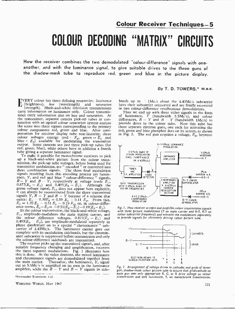
How the receiver combines the two demodulated "colour- difference" signals with one - another, and with the luminance signal, to give suitable drives to the three guns of the shadow -mask tube to reproduce red, green and blue in the picture display.
EVERY colour has three defining properties: luminance (brightness), hue (wavelength) and saturation (strength). Black- and -white television transmissions
carry information on luminance only. Colour transmis- sions carry information also on hue and saturation. At the transmitter, separate camera pick -up tubes in con- junction with an optical colour separation system analyse the scene into three signals corresponding to the primary colour components red, green and blue. After com- pensation for receiver display tube non -linearity, three colour voltages emerge (red = ER, green E,; and blue = Err) available for modulating the transmitter output. Some cameras use just three pick -up tubes (for red, green, blue), while others have in addition a fourth tube giving a separate luminance signal.
To make it possible for monochrome receivers to pick up a black -and -white picture from the colour trans- mission, the pick -up tube voltages, before being used for transmitter modulation, are " encoded " or converted into three combination signals. The three final modulation signals resulting from this encoding process are lumin- ance, Y, and red and blue " colour- difference " signals, R- Y and B -Y, respectively at voltage levels E), 0.877(ER - Ey) and 0.493(E, - Ey). Although the green voltage signal, Er;, does not appear here explicitly, it can always be reconstituted from the three transmitted signals Y, R -Y and B -Y because of a relation that exists: Ey = 0.30ER + 0.59 EE + 0.11 ER. From this, EG = 1.70 Ey - 0.51 ER - 0.19 EB, or, in colour- differ- ence terms, EG -Ey= -0 51(ER- El,)- 0.19(ER -Ey).
In the colour transmission, the black- and -white voltage, Ei., amplitude -modulates the main station carrier, and the colour difference voltages, 0.877(ER - E)) and 0.493(ER - Ey), are amplitude -modulated separately in phase quadrature on to a special " chrominance " sub - carrier of 4.43Mc /s. The luminance carrier goes out complete with its modulation sidebands, but the chromin- ance subcarrier is suppressed before transmission and only the colour- difference sidebands are transmitted.
The receiver picks up the transmitted signals, and, after suitable frequency changing and amplification, recovers the three separate modulations. Fig. 1 illustrates how this is done. At the video detector, the mixed luminance and chrominance signals are demodulated together from the main carrier. Thereafter, the luminance, Y, signal out to 5.5Mcis is amplified on its own in the luminance amplifier, while the R -Y and B -Y signals in side-
*Newmarket Transistors Ltd.
WIRELESS WORLD, MAY 1967
By T. D. TOWERS,* M.B.E.
bands up to 1Mcr's about the 4.43Mc /s subcarrier have their subcarrier reinserted and are finally recovered in two colour- difference synchronous demodulators.
Thus we end up with three video signals in the form of luminance, Y (bandwidth 5.5Mc /s), and colour differences, R -Y and B -Y (bandwidth 1Mc /s) to provide drive to the colour tube. Now this tube has three separate electron guns, one each for activating the red, green and blue phosphor dots on its screen, as shown in Fig. 2. The red gun requires a voltage, ER, between
5'5Mcls BAND OF VISION MODULATION (INCL. CHROMINANCE
ON 443Mc /s)
0- 5.5Mc /s LUMINANCE MODULATION
LUMINANCE AMPLIFIER
TUNER AND
I.F. AMPLIFIER VIDEO DETECTOR
U.H.F. TRANSMISSION WITH 5.5Mc /s BAND OF
VISION FREQUENCIES
4'43 ± I Mc /s
CHROMINANCE MODULATION
55Mc/s WIDEBAND
Y
IMc/s NARROW W.B.
R Y CHROMINANCE
AMPLIFIER & 4-43Mc/s
CARRIER REINSERTION
SECTION
R -Y CHROM. DEMODULATOR
I Mc/s NARROW W.B.
B Y
B -Y CHROM. DEMODULATOR
Fig. I. How receiver accepts and amplifies colour transmission signals with three picture modulations (Y on main carrier and R -Y, B -Y on colour subcarrier frequency) and extracts the modulations separately to provide signals for ultimately driving colour picture tube.
jCATHODES
} GRIDS
Y
R-Y I I
I
I
I
I
B
G-Y i
B-Y
ELECTRON BEAMS TO
I
I
G
SCREEN PHOSPHOR DOTS R
Fig. 2. Arrangement of voltage drives to cathodes and grids of three - gun, shadow -mask colour picture tube to ensure that grid -cathode on each gun sees only appropriate R, G, or B drive voltage on colour transmission and only luminance, Y, on monochrome transmission.
221
www.americanradiohistory.com
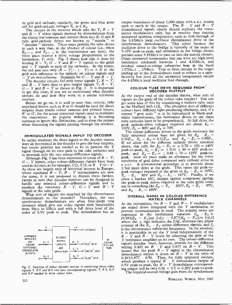
its grid and cathode; similarly, the green and blue guns call for grid -cathode voltages EG aid En.
The circuit s in the receiver which take the Y, R -Y and B -Y video signals derived by demodulation from the colour transmission and convert them into R, G and B tube grid- cathode drives are known as " matrix " or
decoder " circuits. These must provide the tube drives in such a way that, in the absence of colour (i.e., when ER_ Y and EB _
Y in the transmission are zero), the three guns receive, a drive voltage proportional to the luminance, Y, only. Fig. 2 shows how this is done by feeding R Y, G -Y and B -Y signals to the grids and -Y signals to each of the cathodes. In the result, the red gun sees only (R - Y) - (- Y) = R at the grid with reference to the cathode on colour signals and + Y on monochrome. Similarly for G -Y and B - Y.
The decoder circuits fed with input signals Y, R - Y, and B -Y have thus to give output signals Y, R - Y, G -Y and B - Y as shown in Fig. 3. It is important to get this clear, if you are to understand what decoder circuits do and how they work in a colour television receiver.
Before we go on, it is well to note that, strictly, only unprimed letters such as R or G should be used for direct outputs from studio colour cameras and primed letters, R' or G', for the actual corrected signals used to modulate the transmitter. In popular writing, it is becoming common to ignore this distinction, and to drop the primes when discussing the signals passing through the receiver.
DEMODULATED SIGNALS INPUT TO DECODER
In earlier receivers the three inputs to the decoder matrix were all intermixed in the decoder to give the four outputs, but recent practice has tended to be to process the Y signal through on its own path to the tube cathodes and to intermix only the two colour- difference signals.
Although Fig. 3 has been expressed in terms of R -Y, G -Y inputs, other colour- difference signals have been used in the past, as for example, I /Q, X /Z, or R -Y /G- Y. As these are largely only of historical interest in Europe, where equiband R - Y, B -Y transmissions are now the norm, it is not proposed to discuss these further, except to note that decoder matrices can be designed to handle any selected colour- difference signals and to produce the necessary R - Y, G -Y and B -Y signals at the tube grids.
What sort of signals are supplied by the chrominance demodulators to the decoder? Nowadays, the two synchronous demodulators are often four -diode ring elements which give out video signals with bandwidths from 50c /s to 1Mc /s and with a full drive level of the order of 0.5V peak to peak. The demodulator has an
LUMINANCE
AMPLIFIER AND
COLOUR
DIFFERENCE DEMODULATOR
OUTPUTS
R-Y
DECODER
MATRIX
CIRCUITS
AND
AMPLIFIERS
R -Y
G-Y
B-Y B-Y
CATHODES
"RED'GRID
"GREEN" GRID
"BLUE" GRID
OF
COLOUR PICTURE
TUBE
Fig. 3. Function of co our decoder section in converting three video
signals Y, R -Y and B -Y into four corresponding signals, Y, R -Y, G -Y and B -Y needed to drive colour tube.
222
output impedance of about 1,000 ohms with a d.c. return path to earth in the source. The R -Y and B -Y demodulated signals ideally should replicate the trans- mitter modulations only, but in practice they contain unwanted spurious components, such as leak- through of the 4.43Mc /s local oscillator chrominance drive to the synchronous demodulators. This arises because the oscillator drive to the bridge is typically of the order of 5 -10V peak -to -peak, and unbalance in the bridge diodes permits some 4.43Mc /s to pass on into the matrix circuits. Other unwanted components that can arise are high -level luminance sidebands between 1 and 4.43Mc /s, and residual sound -to- colour subcarrier beat in the band 1.57Mcís _L- 150kc /s. Trap or filter circuits in the stages leading up to the demodulators tend to reduce to a satis- factorily low level all the unwanted components except the 4.43Mc!s local oscillator feed through.
COLOUR TUBE DRIVE REQUIRED FROM DECODER OUTPUT
At the output end of the decoder matrix, what sort of signals do the grids of the colour tube require? You can get some idea of this by considering a modern tube such as the Mullard A63 -11X. The phosphor dots of different colours have different light- producing efficiency, and, if a correct " grey scale " is to be reproduced in black -and- white transmissions, the luminance drives to the three tube cathodes have to be proportioned. At full drive the peak cathode -drive voltages required are about ER = 100V, EG = 80V and EB = 70V.
The colour -difference drives to the grids necessary for fully saturated colour bars are given by ER - EY = 0.70Er, EG- EY= 0.41E1, and EB- Ey= 0.89E1. If we allow for the different cathode drives specified above, this calls for ER - E1 = + 0.70 x 100 = 140V peak -to -peak, EE - E1 = ± 0.41 x 80 = 66V peak -to- peak, and EB - E1 = + 0.89 x 70 = 125V peak -to- peak. Now we must make an allowance for the lower sensitivity of grid drive compared with cathode drive in a c.r.t. A conventional procedure is to provide about 1 /3rd more drive at the grids. This raises the peak -to- peak voltages required at the grids to ER - E1 = 185V, EG - EY = 88V and EB - E1 = 167V. Finally, if we allow a further 10% margin against component ageing, the peak -to -peak drives required at the tube grids come out to something like ER - E1 = 200V, E(, EY = 95V, and EB - E1 = 180V.
OVERALL GAINS IN COLOUR DIFFERENCE MATRIX CHANNELS
At the transmitter, the R -Y and B -Y modulations are scaled down compared with the Y modulation to prevent overmodulation in total. The relative ratios are expressed in the modulation equation EM = EY -I-
[0.493(ER - EY)sin 2rrf ft ± 0.877(ER - E1)cos 27rfct] where the + sign indicates the PAL alternate -line phase reversal of the ER - EY colour- difference signals, and L is the chrominance subcarrier frequency. In the receiver, it is practicable to set the Y level independently of the R -Y and B -Y levels by adjusting the gain of the Y luminance amplifier on its own. The colour- difference signals decoder must, however, provide for the different scaling 0.493 on B -Y and 0.877 on R - Y. This means that the peak B -Y signal at the chrominance demodulator output is down on R -Y in the ratio of 0.493 0.877 = 0.56. Thus, for fully saturated colours, which produce a typical R -Y demodulator output of 0.5V peak -to -peak, the B -Y demodulator correspond- ing output will be only 0.56 x 0.5 = 0.28V peak -to -peak.
The required overall voltage gain from the synchronous
WIRELESS WORLD, MAY 1967
www.americanradiohistory.com
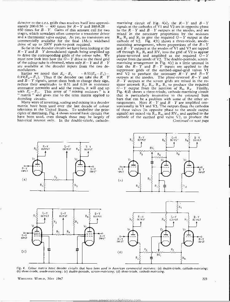
detector to the c.r.t. grids thus resolves itself into approxi- mately 200 0.56 = 400 times for R- Y and 180/0.28 = 650 times for B- Y. Gains of this amount call for two stages, which nowadays often comprise a transistor driver and a thermionic valve output. As yet, no transistors are commercially available for the final 1Mcis wideband drive of up to 200V peak -to -peak required.
So far in the decoder circuits we have been looking at the R- Y and B- Y demodulated signals being amplified up to drive the corresponding grids of the colour tube. We must now look into how the G- Y drive to the third grid of the colour tube is obtained, when only R- Y and B- Y are available at the decoder inputs from the two de- modulators.
Earlier we noted that EG -E,, _ - 0.51(ER -E,.)- 0.19(E, - Ei). Thus if the decoder can take the R- Y and B -Y signals, invert them both to change their sign, reduce their amplitudes to 0.51 and 0.19 in resistance attenuator networks and add the results, it will end up with E(; - E}.. This array of " mixing resistors " is a " matrix " and gives rise to the term matrix applied to decoding circuits.
Many ways of inverting, scaling and mixing in a decoder matrix have been used over the last decade of colour television in the United States. To underline the prin- ciples of matrixing, Fig. 4 shows several basic circuits that have been used, even though these may be largely of historical interest only. In the double- triode, cathode-
R -Y OUTPUT
1
OuTPÚT R, oUT úT A
R -Y INPUT
(e-)
B -Y INPUT
matrixing circuit of Fig. 4(a), the R- Y and B- Y signals at the cathodes of VI and V2 are in opposite phase to the R- Y and B- Y outputs at the anodes, and are mixed in the necessary proportions by the resistors R2, R3 and R5 to give the required G- Y output at the cathode of V2. Fig. 4(b) shows a three- triode, anode - matrixing arrangement, where proportions of the R -Y and B- Y outputs at the anodes of VI and V3 are tapped off through R3, R2 and RV, into the grid of V2 to appear phase- inverted and amplified as the required G- Y output from the anode of V2. The double -pentode, screen matrixing arrangement in Fig. 4(c) is a little unusual in that the R- Y and B - Y inputs are applied to the suppressor grids of the earthed -signal -grid valves VI and V2 to produce the necessary R -Y and B -Y outputs at the anodes. The phase- reversed R- Y and B- Y outputs at the screen grids are mixed in the re- sistor network R2, R;,, R R; to produce the required G- Y output from the junction of R,, R,. Finally, Fig. 4(d) shows a three -triode, cathode -matrixing circuit that is particularly insensitive to the coloured hum bars that can be a problem with some of the other ar- rangements. Here R- Y and B- Y are amplified con- ventionally in V1 and V3. The outputs from the cathodes of these valves (in opposite phase to the anode output signals) are mixed via R3, Rn, and RV and applied to the cathode of the earthed grid valve V2, to produce the
Continued en next page
R -Y G -Y OUTPUT RR OUTPUT
Fig. 4. Colour matrix basic decoder circuits that have been used in American commercial receivers: (a) double- triode, cathode -matrixing; (b) three - triode, anode -matrixing; (c) double -pentode, screen -matrixing; (d) three -triode, cathode- matrixing.
WIRELESS WORLD, MAY 1967 223
www.americanradiohistory.com
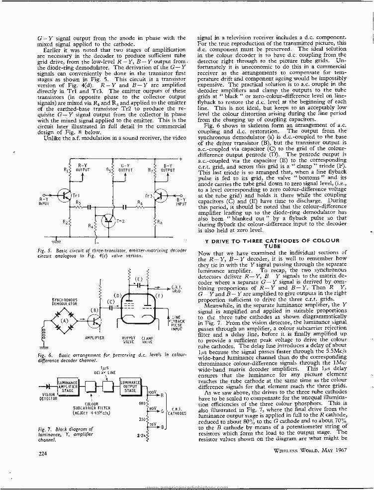
G- Y signal output from the anode in phase with the mixed signal applied to the cathode.
Earlier it was noted that two stages of amplification are necessary in the decoder to produce sufficient tube grid drive, from the low -level R- Y, B -Y output from the diode -ring demodulator. The derivation of the G- Y signals can conveniently be done in the transistor first stages as shown in Fig. 5. This circuit is a transistor version of Fig. 4(d). R- Y and B- Y are amplified directly in Trl and Tr3. The emitter outputs of these transistors (in opposite phase to the collector output signals) are mixed via R, and Re and applied to the emitter of the earthed -base transistor Tr2 to produce the re- quisite G -Y signal output from the collector in phase with the mixed signal applied to the emitter. This is the circuit later illustrated in full detail in the commercial design of Fig. 8 below.
Unlike the a.f, modulation in a sound receiver, the video
Fig. 5. Basic circuit of three -transistor, emitter -matrixing decoder circuit analogous to Fig. 4(c) valve version.
SYNCHRONOUS DEMODULATOR
(B)
AMPLIFIER OUTPUT CLAMP VALVE VALVE
C.R.T. GRID
LINE FLYBACK
PULSE INPUT
Fig. 6. Basic arrangement for preserving d.c. levels in colour - difference decoder channel.
VISION DETECTOR
LUMINANCE AMPLIFIER
STAGE
1/LS DELAY LINE
COLOUR SUBCARRIER FILTER
(REJECT 4.43Mc /s)
Fig. 7. Block diagram of luminance, Y, amplifier channel.
224
LUMINANCE OUTPUT STAGE
680
330
Z2k
I00V
80V
70V
C.R.T. CATHODES
signal in a television receiver includes a d.c. component. For the true reproduction of the transmitted picture, this d.c. component must be preserved. The ideal solution in the colour decoder is to have d.c. coupling from the detector right through to the picture tube grids. Un- fortunately it is uneconomic to do this in a commercial receiver as the arrangements to compensate for tem- perature drift and component ageing would be impossibly expensive. The practical solution is to a.c. couple in the decoder amplifiers and clamp the outputs to the tube grids at " black " or zero -colour- difference level on line - flyback to restore the d.c. level at the beginning of each line. This is not ideal, but keeps to an acceptably low level the colour distortion arising during the line period from the charging up of coupling capacitors.
Fig. 6 shows in skeleton form an arrangement of a.c. coupling and d.c. restoration. The output from the synchronous demodulator (a) is d.c.- coupled to the base of the driver transistor (B), but the transistor output is a.c.- coupled via capacitor (C) to the grid of the colour - difference output pentode (D). The pentode output is a.c.- coupled via the capacitor (E) to the corresponding c.r.t. grid, and across this grid is a " clamp " triode (F). This last triode is so arranged that, when a line flyback pulse is fed to its grid, the valve " bottoms " and its anode carries the tube grid down to zero signal level, (i.e., to a level corresponding to zero colour- difference voltage at the tube grid) and holds it there while the coupling capacitors (C) and (E) have time to discharge. During this period, it should be noted that the colour- difference amplifier leading up to the diode -ring demodulator has also been " blanked out " by a flyback pulse so that during flyback the colour -difference input to the decoder is also held at zero level.
Y DRIVE TO THREE CATHODES OF COLOUR TUBE
Now that we have examined the individual sections of the R -Y, B -Y decoder, it is well to remember how they tie in with the Y signal passing through the separate luminance amplifier. To recap, the two synchronous detectors deliver R- Y, B- Y signals to the matrix de- coder where a separate G -Y signal is derived by com- bining proportions of R- Y and B -Y. Then R- Y, G- Y and B- Y are amplified to give outputs in the right proportion sufficient to drive the three c.r.t. grids.
Meanwhile, in the separate luminance amplifier, the Y signal is amplified and applied in suitable proportions to the three tube cathodes as shown diagrammatically in Fig. 7. From the vision detector, the luminance signal passes through an amplifier, a colour subcarrier rejection filter and a delay line, before it is finally amplified up to provide a sufficient peak voltage to drive the colour tube cathodes. The delay line introduces a delay of about lµs because the signal passes faster through the 5.5Mc /s wide -band luminance channel than do the corresponding chrominance colour- difference signals through the 1Mc/ wide -band matrix decoder amplifiers. This 1µs delay ensures that the luminance for any picture element reaches the tube cathode at the same time as the colour difference signals for that element reach the three grids.
As we saw above, the drives to the three tube cathodes have to be scaled to compensate for the unequal illumina- tion efficiencies of the three colour phosphors. This is also illustrated in Fig. 7, where the final drive from the luminance output stage is applied in full to the R cathode, reduced to about 80% to the G cathode and to about 70% to the B cathode by means of a potentiometer string of resistors which form the load to the output stage. The resistor values shown on the diagram are what might be
WIRELESS WORLD, MAY 1967
www.americanradiohistory.com
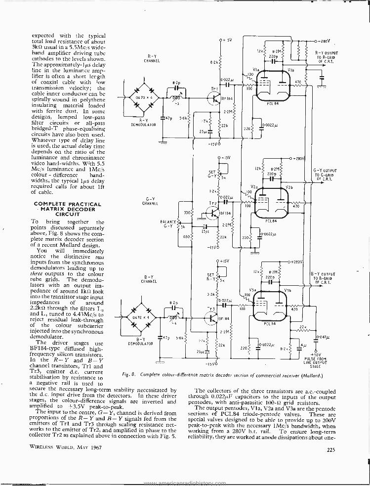
expected with the typical total load resistance of about 3k S2 usual in a 5.5Mc s wide - band amplifier driving tube cathodes to the levels shown. The approximately -1µs delay line in the luminance amp- lifier is often a short ler.gth of coaxial cable with low transmission velocity; the cable inner conductor can be spirally wound in polythene insulating material loaded with ferrite dust. In some designs, lumped low -pass filter circuits or all -pass bridged -T phase -equalising circuits have also been used. Whatever type of delay line is used, the actual delay time depends on the ratio of the luminance and chrominance video hand- widths. With 5.5 Mc /s luminance and 1Mc,'s colour - difference band- widths, the typical lµs delay required calls for about lft of cable.
COMPLETE PRACTICAL MATRIX DECODER
CIRCUIT To bring together the points discussed separately above, Fig. 8 shows the corn- plete matrix decoder section of a recent Mullard design.
You will immediately notice the distinctive two inputs from the synchronous demodulators leading up to three outputs to the colour tube grids. The demodu- lators with an output im- pedance of around 1kS2 look into the transistor stage input impedances of around 2.2k S2 through the filters L3 and L4 tuned to 4.43Mc /s to reject residual leak- through of the colour subcarrier injected into the synchronous demodulator.
The driver stages use BF184 -type diffused high - frequency silicon transistors. In the R- Y and B- Y channel transistors, Trl and Tr3, emitter d.c. current stabilisation by resistance to a negative rail is used to
R -Y CHANNEL 82k
+ISV
12k 82M
+280V
R-Y OUTPUT To R-GRID OF C.R.T.
8.2p 0.022y
Tri
BF184 PCL 84.
R -Y DEMODULATOR
47p 5.6k
0.0022/1
-15V
0 +280V
SET
G -Y 5
12k 82M 220p
G-Y OUTPUT TO G-GRID
OF C.R.T.
G -Y CHANNEL
B -Y CHANNEL
V22 I2k 100
0022/1 --
BALANCE G -Y
BF 184
2.2M
25/L
-ISV
SET B -Y
3.3k
8-2p
Tra
0A70 x 4
22k
+15V
5
0022/1
BF184
22M
22k
PCL 84
10.0022/1
0 +280V
12k 82M 220p
B-Y OUTPUT TO B-GRID OF C.R.T.
V3a 1 f . 3b
100 I T
B -Y DEMODULATOR
T47p 56k P7k
PCL 84
0022/1
25/1 B2k
-15V
J 47/1
471 T
+50V T PULSE FROM LINE OUTPUT
STAGE
Fig. 8. Complete colour -difference matrix decoder section of commercial receiver (Mullard.)
secure the necessary long -term stability necessitated by the d.c. input drive from the detectors. In these driver stages, the colour- difference signals are inverted and amplified to --3.5V peak -to -peak.
The input to the centre, G- Y, channel is derived from proportions of the R- Y and B- Y signals fed from the emitters of Trl and Tr3 through scaling resistance net- works to the emitter of Tr2, and amplified in phase to the collector Tr2 as explained above in connection with Fig. 5.
WIRELESS WORLD, MAY 1967
The collectors of the three transistors are a.c.- coupled through 0.022µF capacitors to the inputs of the output pentodes, with anti -parasitic 100 -fl grid resistors.
The output pentodes, Vla, V2a and V3a are the pentode sections of PCL84 triode -pentode valves. These are special valves designed to be able to provide up to 200V peak -to -peak with the necessary 1Mc /s bandwidth, when working from a 280V h.t. rail. To ensure long -term reliability, they are worked at anode dissipations about one-
225
www.americanradiohistory.com
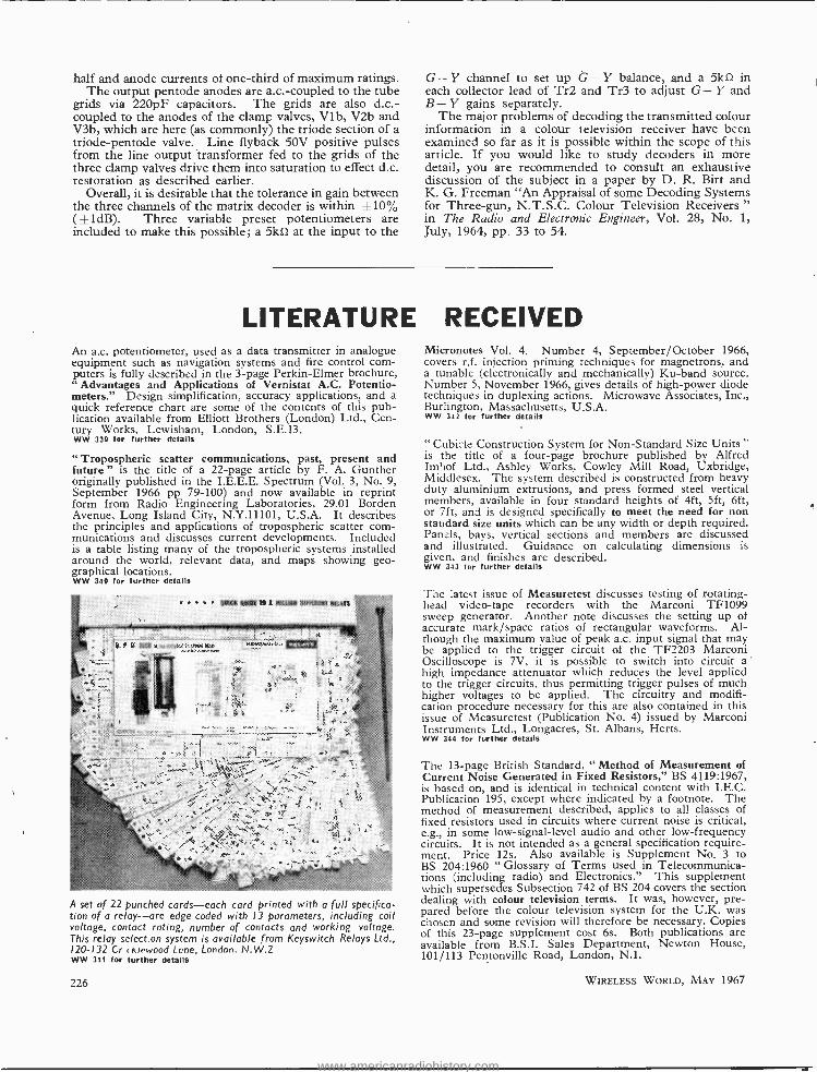
half and anode currents of one -third of maximum ratings. The output pentode anodes are a.c.- coupled to the tube
grids via 220pF capacitors. The grids are also d.c.- coupled to the anodes of the clamp valves, Vlb, V2b and V3b, which are here (as commonly) the triode section of a triode- pentode valve. Line flyback 50V positive pulses from the line output transformer fed to the grids of the three clamp valves drive them into saturation to effect d.c. restoration as described earlier.
Overall, it is desirable that the tolerance in gain between the three channels of the matrix decoder is within ±10% (±1dB). Three variable preset potentiometers are included to make this possible; a 5kS2 at the input to the
G- Y channel to set up G- Y balance, and a 5k0 in each collector lead of Tr2 and Tr3 to adjust G- Y and B- Y gains separately.
The major problems of decoding the transmitted colour information in a colour television receiver have been examined so far as it is possible within the scope of this article. If you would like to study decoders in more detail, you are recommended to consult an exhaustive discussion of the subject in a paper by D. R. Birt and K. G. Freeman "An Appraisal of some Decoding Systems for Three -gun, N.T.S.C. Colour Television Receivers " in The Radio and Electronic Engineer, Vol. 28, No. 1, July, 1964, pp. 33 to 54.
LITERATURE RECEIVED An a.c. potentiometer, used as a data transmitter in analogue equipment such as navigation systems and fire control com- puters is fully described in the 3 -page Perkin -Elmer brochure, " Advantages and Applications of Vernistat A.C. Potentio- meters." Design simplification, accuracy applications, and a quick reference chart are some of the contents of this pub- lication available from Elliott Brothers (London) Ltd., Cen- tury Works, Lewisham, London, S.E.13. WW 339 for further details
" Tropospheric scatter communications, past, present and future " is the title of a 22 -page article by F. A. Gunther originally published in the I.E.E.E. Spectrum (Vol. 3, No. 9, September 1966 pp 79 -100) and now available in reprint form from Radio Engineering Laboratories, 29.01 Borden Avenue, Long Island City, N.Y.11101, U.S.A. It describes the principles and applications of tropospheric scatter com- munications and discusses current developments. Included is a table listing many of the tropospheric systems installed around the world, relevant data, and maps showing geo- graphical locations. WW 340 for further details
A set of 22 punched cards -each card printed with a full specifica- tion of a relay -are edge coded with 13 parameters, including coil voltage, contact rating, number of contacts and working voltage. This relay select. on system is available from Keyswitch Relays Ltd., 120 -132 Cr sklewood Lone, London. N.W.2 WW 341 for further details
226
Micronotes Vol. 4. Number 4, September /October 1966, covers r.f. injection priming techniques for magnetrons, and a tunable (electronically and mechanically) Ku -band source. Number 5, November 1966, gives details of high -power diode techniques in duplexing actions. Microwave Associates, Inc., Burlington, Massachusetts, U.S.A. WW 342 for further details
" Cubicle Construction System for Non -Standard Size Units " is the title of a four -page brochure published by Alfred Imhof Ltd., Ashley Works, Cowley Mill Road, Uxbridge, Middlesex. The system described is constructed from heavy duty aluminium extrusions, and press formed steel vertical members, available in four standard heights of 4ft, 5ft, 6ft, or 7ft, and is designed specifically to meet the need for non standard size units which can be any width or depth required. Panels, bays, vertical sections and members are discussed and illustrated. Guidance on calculating dimensions is given, and finishes are described. WW 343 for further details
The latest issue of Measuretest discusses testing of rotating - head video -tape recorders with the Marconi TF1099 sweep generator. Another note discusses the setting up of accurate mark /space ratios of rectangular waveforms. Al- though the maximum value of peak a.c. input signal that may be applied to the trigger circuit of the TF2203 Marconi Oscilloscope is 7V, it is possible to switch into circuit a high impedance attenuator which reduces the level applied to the trigger circuits, thus permitting trigger pulses of much higher voltages to be applied. The circuitry and modifi- cation procedure necessary for this are also contained in this issue of Measuretest (Publication No. 4) issued by Marconi Instruments Ltd., Longacres, St. Albans, Herts. WW 344 for further details
The 13 -page British Standard, " Method of Measurement of Current Noise Generated in Fixed Resistors," BS 4119:1967, is based on, and is identical in technical content with I.E.C. Publication 195, except where indicated by a footnote. The method of measurement described, applies to all classes of fixed resistors used in circuits where current noise is critical, e.g., in some low- signal -level audio and other low- frequency circuits. It is not intended as a general specification require- ment. Price 12s. Also available is Supplement No. 3 to BS 204:1960 " Glossary of Terms used in Telecommunica- tions (including radio) and Electronics." This supplement which supersedes Subsection 742 of BS 204 covers the section dealing with colour television terms. It was, however, pre- pared before the colour television system for the U.K. was chosen and some revision will therefore be necessary. Copies of this 23 -page supplement cost 6s. Both publications are available from B.S.I. Sales Department, Newton House, 101/113 Pentonville Road, London, N.1.
WIRELESS WORLD, MAY 1967
www.americanradiohistory.com
LETTERS TO THE EDITOR The editor does Not necessarily endorse the opinions expressed by his correspondents
The Gyrator - Old Wine in I HAVE a personal belief that an engineer should have a knowledge of engineering history.
Whilst not, in any way, denigrating the current interest in gyrators I must point out that " gyrators " were known, used, and effectively analysed, before the last war. At that time the circuit was called a reactance valve and the analysis given in those days is still appropriate to semi- conductor configurations, with suitable attention to operating conditions. Mr. Sinclair's circuit (March 1967) is a case in point, using a super alpha pair to increase the input impedance offered to the phase splitting circuit.
Of many possibilties, Emrys Williams " Thermionic Valve Circuits," published during the war is a good reference.
T. G. CLARK Astaron Electronics Ltd.,
Poole, Dorset.
The author replies: - THIS note is an answer to the points raised above by Mr. Clark and also to those made by Mr. Donaldson on p. 194 of the April issue. In the interests of brevity and clarity it is best to set out the arguments in a logical sequence rather than to deal with their comments in a disconnected fashion.
For a start, I hope there is no dispute about the impor- tance and significance of the gyrator concept as distinct from its realization as an active circuit. If there is, the best answer is to quote from Tellegen's original paper, in which he lists the properties of five circuit elements as under: -
Resistor: v =Ri, . . . . . . (1)
Inductor : v = L dt , .. (2)
Capacitor : i = Ce-,
Transformer: v,= Lidtl+Mdf,
di v2= Mdt1
L dt2
(3)
(4)
In the special case M2 =L,L2 and L,LI =n2, the trans- former equation becomes:
il = - ni2
Gyrator: 272 = nv,
v,=-Ri2
v2= Rii
J
J
(5)
(6)
Looked at in this way, all of these concepts of circuit ele-.
a New Bottle? ments rank equal in significance. But Mr. Donaldson's point was that it is wrong to attach a corresponding impor- tance to the actual physical realization of the concept as an element of circuit. I disagree profoundly and con- sider that there is enormous engineering merit in con- structing any one of these elements so that it becomes a close approximation to its mathematical specification. The physical realization of an almost ideal gyrator is a task of great complexity.
The admittance matrix of a non -ideal gyrator is: YII yt2
17= (7) Y2t .Y22
The practical problem is to reduce to zero the terms yn, y2, and to make y21, y, 2 into pure conductances of opposite sign. When other constraints are added, such as require- ments for direct -coupling throughout or for operation at extremely high frequency the task is by no means trivial and calls for design competence of a very high order.
It is naïve, if not puerile, to say that reactance modu- lators, developed for a very restricted and limited appli- cation, embody the features of modern high -grade gyrators. At best they can be regarded only as highly degenerate gyrators. I write with some feeling on this topic, having published a paper' giving an exhaustive analysis of various types. I lump with reactance modulators a whole class of electronic filters based on similar principles.
When it comes to network synthesis, there are three distinct approaches which can be made. One involves feedback amplifiers, one makes use of negative impedance converters and the third invokes gyrators. All can be made to do the same job.
In many cases the use of feedback amplifiers involves the synthesis of lossy elements followed by resistance cancellation by some positive feedback technique. Stable Q- factors are difficult to achieve. Negative impedance converters are simpler than gyrators but in many embodi- ments the two ports are heavily loaded by resistances which must be exactly equal in value and which must be non - reactive. Alternatively, special compensation is neces- sary. There are also serious practical difficulties in synthesizing floating elements.
By contrast, in well- designed gyrators2 there is a very large internal negative feedback, typically 80 -140 dB, round the loop consisting of the (unloaded) transadmit- tances. When the gyrator is terminated by capacitance, this feedback is effective down to d.c. so that the opera- ting points are held with great stability. When terminated by inductors or small resistors, the feedback at d.c. is removed but the loading effects still guarantee stability. It is quite feasible to simulate inductors of 200 H with Q- factors of several hundred, maintained with complete stability.
In much of the published work on active filters, not using gyrators, it is essential to use large numbers of close - tolerance components of awkward values. Derisory rates of cut -off, (12 or 24 dB per octave) are achieved even when using quite complex circuits.
WIRELESS WORLD, MAY 1967 227
www.americanradiohistory.com
Again, with good gyrators it is possible to duplicate exactly the performance of high -grade LC filters, even if they involve floating elements.
Admittedly in many standard RC oscillators and filters it is quite possible to cover a 10 -1 frequency range by variation of either R or C, just as it is with gyrators. However, the filter transfer characteristic is quite different in the two cases. RC filters of the Wien bridge or parallel - T type are characterized by a sharp and narrow peak, with poor skirt selectivity. The response of a gyrator filter is that of a high -Q tuned circuit and bears no resem- blance to that of the normal RC types.
Finally, a most important feature of many modern designs of active gyrators is that the circuits are readily producible in microminiature form.
Standardization of a preferred circuit would be less
difficult than in the case of operational amplifiers, yet integrated- circuit versions of these are readily available at reasonable cost.
As regards the alternative ways of looking at the mode of operation of a particular circuit entity, the choice must be
Symbols -in
decided by personal preferences or past experience. I see no particular merit in Mr. Donaldson's approach to the gyrator but it may well appeal to some readers and I have used a similar idea in several previously published papers on impedance converters using feedback amplifiers.
F. BUTLER, Cheltenham,
Glos. References 1. F. Butler, " Reactance Modulator
1948, p. 69. 2. W. H. Holmes, S. Greutzmann, W. E. Heinlein. " High Performance
Direct -Coupled Gyrators," Electronics Letters, (I.E.E.), February, 1967, p. 45.
Theory," Wireless Engineer, March,
Mr. P. E. K. Donaldson asks us to correct a small error in his letter "The Gyrator -Old Wine in a New Bottle ?" in the April issue. In the left -hand column after "Hence a =0" the next equation should read:
Defence of British Standards
WITH reference to the correspondence on symbols in
the March issue.
Resistor. -The zig -zag has been in use, in certain Euro- pean countries, as a winding for many years. Hence the majority of countries favoured the rectangle as the " preferred " symbol with the zig -zag as second choice. The B.S.I. shows the zig -zag, and also the rectangle as
the "objective" symbol in its BS.3939. Any change from previous practice is a nuisance, at the least. The probability that, in the future, all countries will be using the one symbol, the rectangle, makes the change worth while. This rectangle is relatively long and thin, and
there is little likelihood of it being confused with the rectangle for block symbols which always has some text or other symbol within the rectangle.
Logic Diagrams. -The British representatives on the Working Party of I.E.C. technical committee No. 3,
which is preparing logic symbols, have consistently opposed the use of a rectangle to represent logic func- tions. A meeting of this working party (of which I am
a member) was held in London during the week 27th February-3rd March, this year.
The British symbol of a circle to represent a logic
element (gate) as shown in BS.530 Supplement No. 5
was supported by only one other country (Italy). There was, however, considerable support for the British pro- posal that the logic element (gate) should be represented by a distinctive shape, other than the rectangle, and there was majority support for the semi -circle. The working party will, therefore, be proposing to the main committee
1
N RQCtC,
"1'.C.3 that two alternatives be shown for the logic element (gate), viz a semi- circle and a rectangle. The proposal, if accepted, will, in due course, be circulated to National Committees for approval.
The British proposal for a time delay element was also accepted, with a slight amendment, again with the rectangle as an alternative.
London, W.C.2. J. READING
A Dis- Ztrehs -ing Business UNFORTUNATELY I am finding myself agreeing less
and less with the changes in nomenclature proposed fox
such quantities as frequency, magnetic flux, etc. I'm also a little worried about such things as the inter- national bargaining that Mr. Osborne hints at in his
letter in the March issue. Perhaps it will end up with the "mega -doll " or " micro- guy," or the "milli- ivano- vich," if the national prestige angle comes in.
In any case, the commemoration of scientists' and engineers' names in the units do not assist in the under- standing of the physical quantities involved. At least
the term " cycles per second " gives the meaning instantly, as other writers have mentioned. When we teach the sixth form students, do we now have to say " a one hertz pendulum " and when mentioning the periodic time, as we do often in Simple Harmonic Motion will
we have to say " reciprocal hertz " or " ztrehs "? K. SMITH
Physics Dept., Holloway School, London.
Constant Current Circuits- Another Arrangement
I READ with interest the articles and letters about con-
stant current circuits, particularly as I found I had used part of Mr. P. Williams' circuit (September 1966) in a
near -constant current arrangement as part of a voltage stabilizer, about a year ago. This stabilizer was added to a battery operated a.f. generator with the object of
obtaining the maximum useful battery life together with consistent performance during battery life. Thus a
circuit is indicated which
228
(a) produces a stable output at the lowest output voltage consistent with correct operation of the load,
(b) requires a minimum of battery voltage above the stabilized voltage,
(c) causes a minimum of current rise when the battery voltage is high,
(d) requires very little current of its The circuit given here fulfills all
and may be of interest to readers.
WIRELESS WORLD, MAY 1967
own. these requirements,
www.americanradiohistory.com
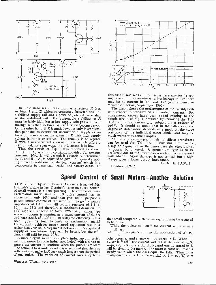
LOAD SUPPLY ` LOAD
Fig.1 Fig.2
Fig.3
In most stabilizer circuits there is a resistor R (e.g. in Figs. 1 and 2) which is connected between the un- siabilized supply rail and a point of potential near that of the stabilized rail. For reasonable stabilization R must be fairly high, but at low supply voltage the current through R is then so low that stabilization becomes poor. On the other hand, if R is made low, not only is stabiliza- tion poor due to insufficient attenuation of supply varia- tions but also the current taken by R with high supply voltage is rather excessive. The remedy is to replace R with a near -constant current circuit, which offers a high impedance even when the p.d. across it is low.
Thus the circuit of Fig. 1 was modified as shown in Fig. 3. L_ is almost constant, provided Ibz remains constant. Now Ib2 =I, which is essentially determined by V, and R,. R, is adjusted to give the required stand- ing current (additional to the load current) which is a compromise between stabilization and battery drain. In
Speed Control of THE criticism by Mr. Stewart (February issue) of Mr. Estaugh's article in last October's issue on speed control of small motors is a little puzzling. He comments, with exclamation mark, that a 1 :9 pulse control has an efficiency of only 10% and then goes on to propose a potentiometer control of the same ratio to give a source impedance of 10. This will require resistors of 1.1 + 10 = say 11>Z and therefore a continuous drain on the 12V supply of at least lA (over 12W) at all times. So when his motor is running at a mean current of 0.15A and back e.m.f. of 1.2V ( =0.18 watt) the efficiency is less than 11 % -my turn to have an exclamation mark! He certainly achieves better speed regulation but at a rather heavy price, in elegance if not in cash. A regulated supply of conventional type will be better, but the effi- ciency will still be only 10 %.
A more elegant solution is to place inductance in series with the motor (its own inductance helps) with a diode to enable the current to continue when the pulser is " off." The action is best understood if it is assumed that there is sufficient L to make L/R very much longer than the period of one pulse. The variation of current over a cycle is
WIRELESS WORLD, MAY 1967
E
0 2 H
- CIRCUIT FIG.3
--- 1, R=6eof1 .........
...,
i/ i y- / ./
/' / ,
... '''
4
3
D
6'0 5'8 J° 56;o$ 5'4
52
5'05.5 60 65 70 75 80 85 90 95 100 Vin
this case it was set to 1 mA. R, is necessary for " start- ing " the circuit, otherwise with low leakage in Tr3 there may be no current in Trl and Tr2 (see reference to " bistable " action, September, 1966).
The graph shows the performance of the circuit, both with respect to stabilization and no -load current. For comparison, curves have been added relating to the simple circuit of Fig. 1, obtained by removing the Trl- Tr2 part of the circuit and substituting a resistor of 68011. It should be noted that in the latter case the degree of stabilization depends very much on the slope resistance of the individual zener diode, and may be much worse with some samples.
Almost any n- p- n -p -n -p pair of silicon transistors can be used for Trl, Tr2. Transistor Tr3 can be p -n -p or n -p -n, but in the latter case the circuit must of course be inverted. A germanium type is to be preferred due to the lower base -emitter drop compared with silicon. Again the type is not critical, but a high /3 type gives a lower output impedance.
G. N. E. PASCH London, N.W.2.
Small Motors -Another Solution L
then small compared with the average and may be assun ed to be linear.
While the pulser is " on " the current will rise at a
rate E
L m amps /sec due to the application of E -v,,,
volts across L, and energy will be stored in L. When the pulser is " off " the current will fall at the rate of v,,, /L amps /sec, flowing via the diode, and energy stored in L will be given to the motor. The mean current will reach a steady value when the rises equal the falls. Thus for a mark /space ratio of 1 : 9, (E- v,,,) /L x 1 = (v,,, /L) x 9
229
www.americanradiohistory.com
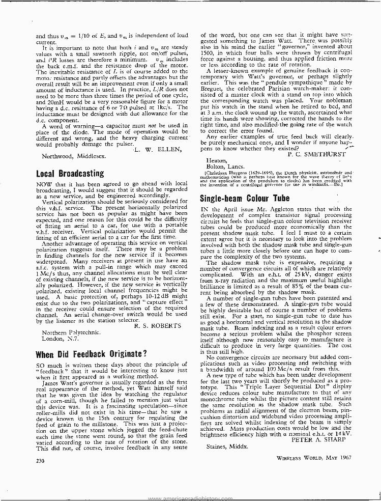
and thus vm = 1 /10 of E, and vm is independent of load current.
It is important to note that both i and vm are steady values with a small sawtooth ripple, not on /off pulses, and i2R losses are therefore a minimum. vm includes the back e.m.f. and the resistance drop of the motor. The inevitable resistance of L is of course added to the motor resistance and partly offsets the advantages but the overall result will be an improvement even if only a small amount of inductance is used. In practice, L/R does not need to be more than three times the period of one cycle, and 20mH would be a very reasonable figure for a motor having a d.c. resistance of 6 or 7 i2 pulsed at lkc /s. The inductance must be designed with due allowance for the d.c. component.
A word of warning -a capacitor must not be used in place of the diode. The mode of operation would be different and wrong, and the heavy charging current would probably damage the pulser.
L. W. ELLEN, Northwood, Middlesex.
Local Broadcasting NOW that it has been agreed to go ahead with local broadcasting, I would suggest that it should be regarded as a new service, and be engineered accordingly.
Vertical polarization should be seriously considered for this vh.f. service. The present horizontally polarized service has not been as popular as might have been expected, and one reason for this could be the difficulty of fitting an aerial to a car, for use with a portable v.h.f. receiver. Vertical polarization would permit the fitting of an efficient aerial to a car for the first time.
Another advantage of operating this service on vertical polarization suggests itself. There may be a problem in finding channels for the new service if it becomes widespread. Many receivers at present in use have an a.f.c. system with a pull -in range which may exceed 1 Mc /s thus, any channel allocations must be well clear of existing channels, if the new service is to be horizont- ally polarized. However, if the new service is vertically polarized, existing local channel frequencies might be used. A basic protection of, perhaps 10 -12 dB might exist due to the two polarizations, and " capture effect " in the receiver could ensure selection of the required channel. An aerial change -over switch would be used by the listener as the station selector.
R. S. ROBERTS Northern Polytechnic. London, N.7.
When Did Feedback Originate? SO much is written these days about the principle of "feedback" that it would be interesting to know just when it first appeared as a working method.
James Watt's governor is usually regarded as the first real appearance of the method, yet Watt himself said that he was given the idea by watching the regulator of a corn -mill, though he failed to mention just what this device was. It is a fascinating speculation -since roller -mills did not exist in his time -that he saw a
device known in the 15th century for regulating the feed of grain to the millstone. This was just a projec- tion on the upper stone which jogged the feed -chute each time the stone went round, so that the grain feed varied according to the rate of rotation of the stone. This did not, of course, involve feedback in any sense
230
of the word, but one can see that it might have sug- gested something to James Watt. There, was possibly also in his mind the earlier " governor," invented about 1500, in which four balls were thrown by centrifugal force against a housing, and thus applied friction more or less according to the rate of rotation.
A lesser -known example of genuine feedback is con- temporary with Watt's governor, or perhaps slightly earlier. This was the " pendule sympathique " made by Breguet, the celebrated Parisian watch- maker: it con- sisted of a master clock with a stand on top into which the corresponding watch was placed. Your nobleman put his watch in the stand when he retired to bed, and at 3 a.m. the clock wound up the watch, ascertained what time its hands were showing, corrected the hands to the right time, and also modified the going rate of the watch to correct the error found.
Any earlier examples of true feed back will clearly .
be purely mechanical ones, and I wonder if anyone hap- pens to know whether they existed?
P. C. SMETHURST Heaton, Bolton, Lancs.
[Christiaan Huygens (1629 -1695), the Dutch physicist, astforiolnér and mathematician (who is perhaps best known for the wave theory cf lit"t and the application of the pendulum to clocks) has been credited with the invention of a centrifugal governor for use in windmills. -En.]
Single -beam Colour Tube
1N the April issue Mr. Aggleton states that with the development of complex transistor signal processing circuits he feels that single -gun colour television receiver tubes could be produced more economically than the present shadow mask tube. I feel I must to a certain extent agree but it is necessary to look into the problem involved with both the shadow mask tube and single -gun tubes a little more closely before one can hope to com- pare the complexity of the two systems.
The shadow mask tube is expensive, requiring a number of convergence circuits all of which are relatively complicated. With an e.h.t. of 25 kV, danger exists from x -ray radiation and the maximum useful highlight brilliance is limited as a result of 85% of the beam cur- rent being absorbed by the shadow mask.
A number of single -gun tubes have been patented and a few of these demonstrated. A single -gun tube would be highly desirable but of course a number of problems still exist. For a start, no single -gun tube to date has as good a horizontal and vertical resolution as the shadow mask tube. Beam indexing and as a result colour errors become a serious problem whilst the phosphor screen itself although now reasonably easy to manufacture is difficult to produce in very large quantities. The cost is thus still high.
No convergence circuits are necessary but added com- plications such as video processing and switching with a bandwidth of around 100 Mc /s result from this.
A new type of tube which has been under development for the last two years will shortly be produced as a pro- totype. This " Triple Layer Sequential Dot" display device reduces colour tube manufacture to that of any monochrome tube whilst the picture content still retains the same resolution as the shadow mask tube. Such problems as radial alignment of the electron beam, pin- cushion distortion and wideband video processing ampli- fiers are solved whilst indexing of the beam is simply achieved. Mass production costs would be low and the brightness efficiency high with a nominal e.h.t. or 14 kV.
PETER A. SHARP Staines, Middx.
WIRELESS WORLD, MAY 1967
www.americanradiohistory.com
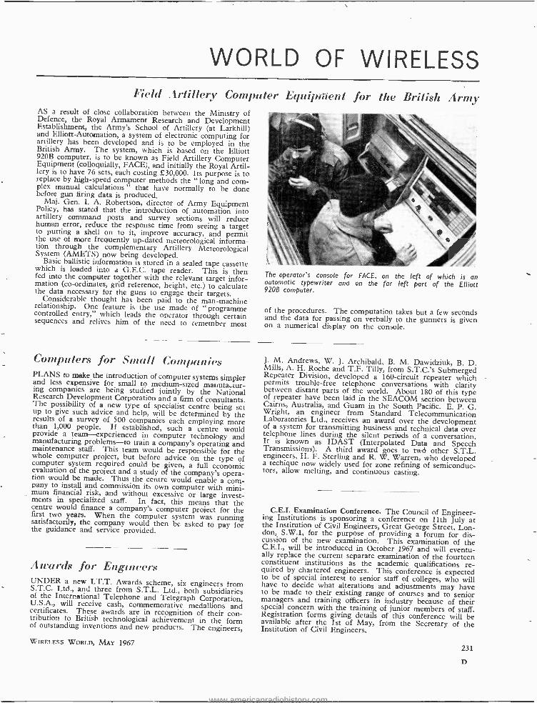
WORLD OF WIRELESS Field Artillery Computer Equipment for the British Army
AS a result of close collaboration between the Ministry of Defence, the Royal Armament Research and Development Establishment, the Army's School of Artillery (at Larkhill) and Elliott- Automation, a system of electronic computing for artillery has been developed and is to be employed in the British Army. The system, which is based on the Elliott 920B computer, is to be known as Field Artillery Computer Equipment (colloquially, FACE), and initially the Royal Artil- lery is to have 76 sets, each costing £30,000. Its purpose is to replace by high -speed computer methods the " long and corn - plex manual calculations " that have normally to be done before gun firing data is produced.
Maj. Gen. I. A. Robertson, director of Army Equipment Policy, has stated that the introduction of automation into artillery command posts and survey sections will reduce human error, reduce the response time from seeing a target to putting a shell on to it, improve accuracy, and permit the use of more frequently up -dated meteorological informa- tion through the complementary Artillery Meteorological System (AMETS) now being developed.
Basic ballistic information is stored in a sealed tape cassette which is loaded into a G.E.C. tape reader. This is then fed into the computer together with the relevant target infor- mation (co- ordinates, grid reference, height, etc.) to calculate the data necessary for the guns to engage their targets.
Considerable thought has been paid to the man -machine relationship. One feature is the use made of " programme controlled entry," which leads the operator through certain sequences and relives him of the need to remember most
The operator's console for IACE, on the left of which is an automatic typewriter ana on the for left part of the Elliott 9206 computer.
of the procedures. The computation takes but a few seconds and the data for passing on verbally to the gunners is given on a numerical display on the console.
Computers for Small Companies PLANS to make the introduction of computer systems simpler and less expensive for small to medium -sized manuta..tur- ing companies are being studied jointly by the National Research Development Corporation and a firm of consultants. The possibility of a new type of specialist centre being set up to give such advice and help, will be determined by the results of a survey of 500 companies each employing more than 1,000 people. If established, such a centre would provide a team-experienced in computer technology and manufacturing problems -to train a company's operating and maintenance staff. This team would be responsible for the whole computer project, but before advice on the type of computer system required could be given, a full economic evaluation of the project and a study of the company's opera- tion would be made. Thus the centre would enable a com- pany to install and commission its own computer with mini- mum financial risk, and without excessive or large invest- ments in specialized staff. In fact, this means that the centre would finance a company's computer project for the first two years. When the computer system was running satisfactorily, the company would then be asked to pay for the guidance and service provided.
Awards for Engineers UNDER a new I.T.T. Awards scheme, six engineers from S.T.C. Ltd., and three from S.T.L. Ltd., both subsidiaries of the International Telephone and Telegraph Corporation, U.S.A., will receive cash, commemorative medallions and certificates. These awards are in recognition of their con- tribution to British technological achievement in the form of outstanding inventions and new products. The engineers,
WIRELESS WORLD, MAY 1967
J. M. Andrews, W. J. Archibald, B. M. Dawidziuk, B. D. Mills, A. H. Roche and T.F. Tilly, from S.T.C.'s Submerged Repeater Division, developed a 160 -circuit repeater which permits trouble -free telephone conversations with clarity between distant parts of the world. About 180 of this type of repeater have been laid in the SEACOM section between Cairns, Australia, and Guam in the South Pacific. E. P. G. Wright, an engineer from Standard Telecommunication Laboratories Ltd., receives an award over the development of a system for transmitting business and technical data over telephone lines during the silent periods of a conversation. It is known as IDAST (Interpolated Data and Speech Transmissions). A third award goes to twci other S.T.L. engineers, H. F. Sterling and R. W. Warren, who developed a techique now widely used for zone refining of semiconduc- tors, allow melting, and continuous casting.
C.E.I. Examination Conference. The Council of Engineer- ing Institutions is sponsoring a conference on 11th July at the Institution of Civil Engineers, Great George Street, Lon- don, S.W.1, for the purpose of providing a forum for dis- cussion of the new examination. This examination of the C.E.I., will be introduced in October 1967 and will eventu- ally replace the current separate examination of the fourteen constituent institutions as the academic qualifications re- quired by chartered engineers. This conference is expected to be of special interest to senior staff of colleges, who will have to decide what alterations and adjustments may have to be made to their existing range of courses and to senior managers and training officers in industry because of their special concern with the training of junior members of staff. Registration forms giving details of this conference will be available after the 1st of May, from the Secretary of the Institution of Civil Engineers.
231
D
www.americanradiohistory.com
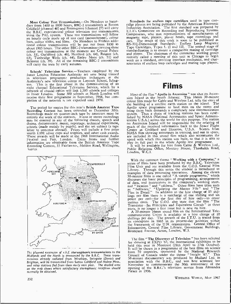
More Colour Test Transmissions. -On Mondays to Satur- days from 1400 to 1800 hours, BBC -2 transmitters at Sutton Goldfield (channel 40) and Bromsgrove (channel 27) will carry the B.B.C. experimental colour television test transmissions, using the PAL system. These test transmissions will follow an hourly cycle made up of test card (monochrome), colour bars, colour slides, and films. On Mondays to Fridays addi- tional colour transmissions will be put out from 1830 to about 1915 hours. The other BBC -2 transmitter carrying these colour test transmissions at the moment are Crystal Palace (ch. 33), Guildford (ch. 46), Hertford (ch. 64), Reigate (ch. 63), Tunbridge Wells (ch. 44), Emley Moor (ch. 51) and Belmont (ch. 28). All of the remaining BBC -2 transmitters will carry the tests by early autumn.
Schools' Television Service.- Teachers employed by the Inner London Education Authority are now being trained in television programme production techniques at the Authority's new television centre at Laycock School, Isling- ton. This is the first phase in the commissioning of an eight channel Educational Television Service, which by a network of coaxial cables will link 1,300 schools and colleges in Inner London. Some 300 schools in North London will receive their first programme in September, 1968, but corn - pletion of the network is not expected until 1970.
The period for entries for this year's British Amateur Tape Recording Contest has been extended to December 30th. Recordings made on quarter -inch tape by amateurs must be entirely the work of the entrants. 1V ono or stereo recordings may be entered in any of the following classes, speech and drama, documentary, music, reportage, technical experiment, schools (made mainly by pupils), and the set subject (a tape letter to someone abroad). Prizes will include a first prize worth £100, silver cups and trophies, and other cash awards. These awards will be made at the 1968 International Audio Festival and Fair, London. Entry forms and further information are obtainable from the British Amateur Tape Recording Contest, 33 Fairlawnes, Maldon Road, Wallington, Surrey.
*SCARBOROUGH
HOLME MOSS
O SHEFFIELD
HEREFORD
SUTTON COLDFIELD
.NORTHAMPTON
WROTHAMO
DOVER
BRIGHTON
Thy planned extension of v.h.f. stereophonic transmissions to the Midlands and the North is announced by the B.B.C. These trans- missions already radiated from Wrotham, Swingate (Dover) and Brighton, will be transmitted from Sutton Coldfield and Holme Moss, and relay stations fed from them early next year. The shaded area on the map shows where satisfactory stereophonic reception should normally be obtained.
232
Standards for endless tape cartridges used in tape cart- ridge players are being published by the American Electronic Industries Association. The first standard was prepared by E.I.A's Committee on Recording and Reproducing Systems Components, who met representatives of manufacturers of magnetic tape, players, player heads, tape recordings and cars. The result of this work is soon to be published as RS- 332 -Dimensional Standards : Endless Loop Magnetic Tape Cartridges, Types I, II and III. The second stage of standardization is to ensure a compatible mating of cartridge and player. The chairman of the committee working group recently called a meeting of this unit at Chicago to begin work on a standard, covering interface mechanics, and char- acteristics of endless loop cartridges and mating tape players.
Films Most of the film " Apollo in Ascension " was shot on Ascen-
sion Island in the South Atlantic. This 16mm 30- minute colour film made for Cable and Wireless Ltd. tells the story of the building of a satellite earth station on the island. The Apollo space programme to land men on the moon and bring them back demands a completely new communication system. Thus a chain of tracking stations has been estab- lished by NASA (National Aeronautics and Space Adminis- tration U.S.A.) across the world for this purpose. The station on Ascension Island will be responsible for the relaying of much of the received information back to the Space Flight Centre at Goddard and Houston, U.S.A. Scenes from NASA film showing astronauts in training, and out in space, are included in this sound film which also accentuates the speed with which this station was built, so that it is able to play its full part in the whole Apollo test programme.
It will be available for hire from Cable & Wireless Ltd., Public Relations Office, Mercury House, Theobalds Road, London, W.C.1.
With the common theme " Working with a Computer," a series of films have been produced by the B.B.C. Television Film Unit and are available from the C.O.I. Central Film Library. Through this series the student is introduced to examples of data processing operations. Among the eleven 30- minute films is one called " A simple programme," which discusses the basic principles of programming, arrangements of data, and instructions in the computer's working store, and " location " and " address." Other films have titles such as " Software," " Updating the Master File " and " The Plan in Detail." In addition to the hire charge of 15 shil- lings per film there is a surcharge of one shilling and six pence per reel -for the first day of hire only -to cover various costs. The C.O.I. also state that the film " The Transistor -Its Principles and Equivalent Circuit" in three parts, is no longer a free issue but is now on hire.
A 20- minute 16mm sound film on the International Tele- communication Union is available at a hire charge of 10
shillings per day. The growth of the I.T.U. is traced from its conception in 1865 to its present -day activities within the framework of the U.N. organization. Central Office of Information, Central Film Library, Government Buildings, Bromyard Avenue, Acton, London, W.3.
The film " The Discovery of Television " has been selected for showing at EXPO '67, the international exhibition to be held this year in Montreal (28th April to 27th October). It will be shown in a programme of the best films on science from 70 countries, sponsored by the National Research Council of Canada under the theme " Insight '67." This 50- minute documentary was produced by Mullard Ltd. in association with the B.B.C., and was first screened last November to commemorate the 30th anniversary of the opening of the B.B.C.'s television service from Alexandra Palace in 1936.
WIRELESS WORLD, MAY 1967
www.americanradiohistory.com
PERSONALITIES Group Captain E. Fennessy, C.B.E.,
director of Plessey Electronics Group, is the chairman of the Electronic Engineer- ing Association for 1967/68. Group Captain Fennessy, who is 55, joined the original Air Ministry radar research team at Bawdsey Manor in 1938 and during the war served on the staff at No. 60 (Radar) Group, R.A.F. After the war he joined Decca and played an important part in helping to establish the Decca Navigator Company. In 1950 he became managing director of the newly formed Decca Radar Ltd. and in 1965 joined Plessey as head of the Electronics Group. He was recently
Group Captain E. Fennessy
appointed chairman of World Satellite Terminals Ltd. the consortium formed by A.E.I., G.E.C. and Plessey to build complete communications satellite ter- minals. Ht was a founder -director of the British Space Development Com- pany and is a member of the National Industrial Space Committee.
Commander H. Pasley -Tyler, R.N. (Retd.), is the new vice -chairman of the E.E.A. Commander Pasley -Tyler is a director and group general manager of Elliott- Automation Ltd., an assistant managing director of Elliott Brothers (London) Ltd., chairman of Elliott Flight Automation Ltd., of Elliott - Automation Radar Systems Ltd., and of Elliott Space and Weapon Automa- tion Ltd., and a director of Elliott -Auto- mation Computers Ltd. Born in 1910, he entered the Royal Naval College, Dartmouth, in 1925 and subsequently specialized as a signals officer. After the war he was in command of a naval training establishment until 1948 when he went to Washington as a member of the British Naval Mission. He retired from the Navy in 1950 and joined Elliotts.
S. H. Cohen recently retired from the position of group chief inspector of the Rank Bush Murphy sound radio and television factories. He had been with the Murphy organization for 28 years.
WIRELESS WORLD, MAY 1967
Recently -elected Fellows of the Royal Society include F. E. Jones, M.B.E., B.Sc., Ph.D., F.I.E.E., M.I.E.R.E., managing director of Nul- lard Ltd; I. Maddock, O.B.E., B.Sc., M.I.E.R.E., controller in the Ministry of Technology; and J. M. Ziman, pro- fessor of theoretical physics in the University of Bristol. Dr. Jones, whose citation reads " For his contributions to radar and infra -red technology, and for his outstanding technological leadership in an advanced industry," has been with Mullard since 1956 prior to which he was in the scientific civil service. He joined the Telecommunications Research Establishment after graduating at King's College, London, in 1940. Mr. Mad- dock, who is elected " for his contribu- tions to the design, engineering and operation of recording systems, includ- ing work on the recording of nuclear explosions," has been in the Ministry of Technology since its formation. He was previously at the Atomic Weapons Research Establishment. Professor Ziman's election is "for his theoretical contributions to solid state physics, especially the study of transport pheno- mena and for his work on the electronic properties of liquid metals."
A. M. Beresford- Cooke, O.B.E., for the past eleven years head of the Plan- ning and Construction Department of the Independent Television Authority, has been appointed deputy chief engineer. After a short period in E.M.I.'s research laboratories he volunteered in 1939 for the Army and ended his service in 1945 as a R.E.M.E. major concerned with radar. Mr. Beresford- Cooke, who is 50, joined the I.T.A. on its formation in
A. M. Beresford -Cooke
1955 prior to which he was concerned with the planning and installation of television studios for the B.B.C. The I.T.A.'s Planning and Construction De- partment is being replaced by two departments. These will be known as the Planning and Propagation Dept. of which A. L. Witham, M.A., will be head,
and the Station Design and Construction Dept., of which T. S. Robson, M.B.E., will be head and H. W. Boutall deputy head. Mr. Witham obtained his M.A. in mechanical sciences at Cambridge and on leaving the University in 1947 joined the B.B.C. He has been with the Authority since 1955 and has been senior engineer (lines) since 1963. He is 40. Mr. Robson (to be head of Station Design and Construction) joined the I.T.A. in 1957 as engineer -in- charge of the Black Hill transmitting station in central Scotland. Immediately prior to that he was for ten years at E.M.I.'s research laboratories. Mr. Robson, who is 44, was with the B.B.C. Engineering Dept. for a few years from 1941 and then served in the Radar Branch of the R.A.F. Mr. Boutall (to be deputy head of Station Design and Construction) who is 40, joined the Authority in 1955 and has been senior engineer (contracts) since 1958. For eleven years before joining the I.T.A. he was with the B.B.C.
I. J. P. James
I. J. P. James, B.Sc., F.I.E.E., M.I.E.R.E., has been appointed general manager of development and produc- tion of the Television Group in E.M.I. Electronics. He joined E.M.I. in 1937 and, since 1951, has been concerned with the development of the company's tele- vision equipment. Most recently he headed the team which designed E.M.I.'s latest colour camera channel Type 2001. In his new position Mr. James, together with the commercial manager Mr. J. D. Tucker, will be re- sponsible for all television equipment.
Professor D. Gabor, Dr.Ing., F.R.S., of Imperial College of Science & Technology, University of London, is to receive the Thomas Young medal and prize of the Institution of Physics and Physical Society for his work on electron and physical optics. Dr. Gabor, who is professor of applied electron physics in the Department of Electrical
233
www.americanradiohistory.com
Engineering at the College, is to receive the award at the I.P.P.S. annual dinner on May 2nd. Well known for his original work on holography and on the flat " picture frame " television tube, he came to this country from Hungary in 1934 and worked in the B.T.H. Research Laboratory (now part of A.E.I.) at Rugby until he joined the staff of Imperial College in 1949. Prior to being appointed professor in 1958 he was Mullard Reader in Electronics.
E. Bonong, who joined the B.B.C. in 1928 as an assistant maintenance engin- eer at Savoy Hill and who has been superintendent engineer (transmitters II) since 1964, has retired and is suc- ceeded by D. A. V. Williams, B.A., M.I.E.E. The superintendent engineer (transmitters II) is responsible for the maintenance of the low -, medium- and high -frequency transmitting stations in the U.K. and overseas. Mr. Bonong was in charge of the B.B.C.'s War Reporting Unit in Italy until 1945 and was seconded to the War Office in 1947 as chief engineer of Radio SEAC, Ceylon. In 1949 he resumed his duties in the B.13.C. Transmitter Department and was appointed head of the transmitter ad- ministrative section. ir. 1961. Mr. Wil-
D. V. A. Williams
hams was educated at Marlborough Col- lege and, after military service, at Trin- ity Hall, Cambridge, where he took an engineering degree. On leaving Cam- bridge in 1950 he joined the B.B.C. and was appointed to the television studios at Alexandra Palace. In 1962 he was appointed as the B.B.C.'s senior engin- eer in New York and on completion of a two -year tour of duty returned to the Transmitter Planning and Installation Department where he became head of the external services unit.
Transitron Electronic Ltd., of Maiden- head, Berks, recently appointed J. Bailey, B.Sc., M.I.E.E., as marketing co- ordinator for international activities through its subsidiary companies and sales agents. Prior to joining Transitron N r. Bailey was technical and publicity officer for Tektronix U.K. Ltd.
Dr. Vladimir K. Zworykin, has been awarded the American National Medal
234
of Science for " major contributions to the instrumentation of science, engineer- ing and television and for his stimulation of the application of engineering to medicine." Dr. Zworykin, who is 76, has been with R.C.A. since 1929 and is now honorary vice -president. He has throughout devoted himself to the acti- vities of the company's research labora- tories and is also responsible for the direction of a Medical Electronics Centre at the Rockefeller Institute in New York.
J. B. Warman, F.I.E.E., departmental chief engineer in the Telecommunica- tions Division of A.E.I., has been awarded the 1966 Prince Philip Medal of the City & Guilds of London Institute " as a mark of recognition of his out- standing achievement " in the telecom- munications industry. Prince Philip will
J. B. Warman
present the award at Buckingham Palace on May 24th. Mr. Warman, who is 41, joined A.E.I. as a student apprentice in 1940 and returned after war service with R.E.M.E. From 1952 to 1965 he was a member of the staff of the Advanced Development Laboratories of the A.E.I. Telecommunications Division. The award, first made in 1962, is restricted to those who have " travelled the City and Guilds path " and have received qualifications by examination provided by the Institute.
M. A. Perry, A.M.I.Mech.E., A.F.R.Ae.S., formerly head of the Air- craft & Automobile Instrumentation Laboratories at the College of Aero- nautics, Cranfield, and now technical director of S. Davall & Sons Ltd., has been appointed to the boards of the associated companies Perivale Controls Company Ltd., and Telford Products Ltd. Mr. Perry started his career with the Royal Aircraft Establishment, Farn- borough, and then studied at the College of Aeronautics where in 1953 he was awarded a post- graduate diploma in electrical engineering. He then worked on the " Seaslug " missile programme at what is now Hawker Siddeley Dynamics after which he returned to the College as lecturer and head of the instrumentation laboratory.
Herbert C. Bostock has been appointed chief inspector of the Sanders Division of Marconi Instruments Ltd. at Steven- age, Herts. He has been in the elec- tronics industry for 25 years and prior to joining Marconi Instruments was chief inspector of the Airborne Com- munications Division, of Elliott Bros., Boreham Wood.
H. C. Bostock
Michael Lee, who has been with Hewlett -Packard Ltd. for four years, has become service manager at the com- pany's marketing and servicing head- quarters at Slough. Before joining H: P. he was deputy head of the trials department of English Electric Aviation at Stevenage. He takes over at Slough from Hugh Smith who is now at Hewlett -Packard's manufacturing divi- sion at South Queensferry, Scotland.
E. J. K. Banks, B.Sc., M.I.E.E., has been appointed chief engineer of Shipton Electronics Ltd. Mr. Banks, who is 41, was with the Telecommunications Department, Malaya, for some years until 1963; he was then controller.
OBITUARY George Rowland Scott -Farnie, C.B.E.,
M.I.E.R.E., deputy chairman and managing director of International Aeradio Ltd., died on March 26th at the age of 55. Throughout the last war he served in the R.A.F. as group captain on special signals intelligence duties, latterly on the staff of General Eisen- hower. In 1946 he joined E.M.I. as assistant to the managing director but thL following year left to become opera- tions manager of International Aeradio which had recently been formed. He became managing director in 1957 and deputy chairman two years ago. A few weeks before his sudden death Mr. Scott -Farnie was appointed chairman of the newly formed Civil Air Transport Industry Training Board by the Minister of Labour. He had been an active radio amateur since before the last war. His call was GSFI.
WIRELESS WORLD, MAY 1967
www.americanradiohistory.com
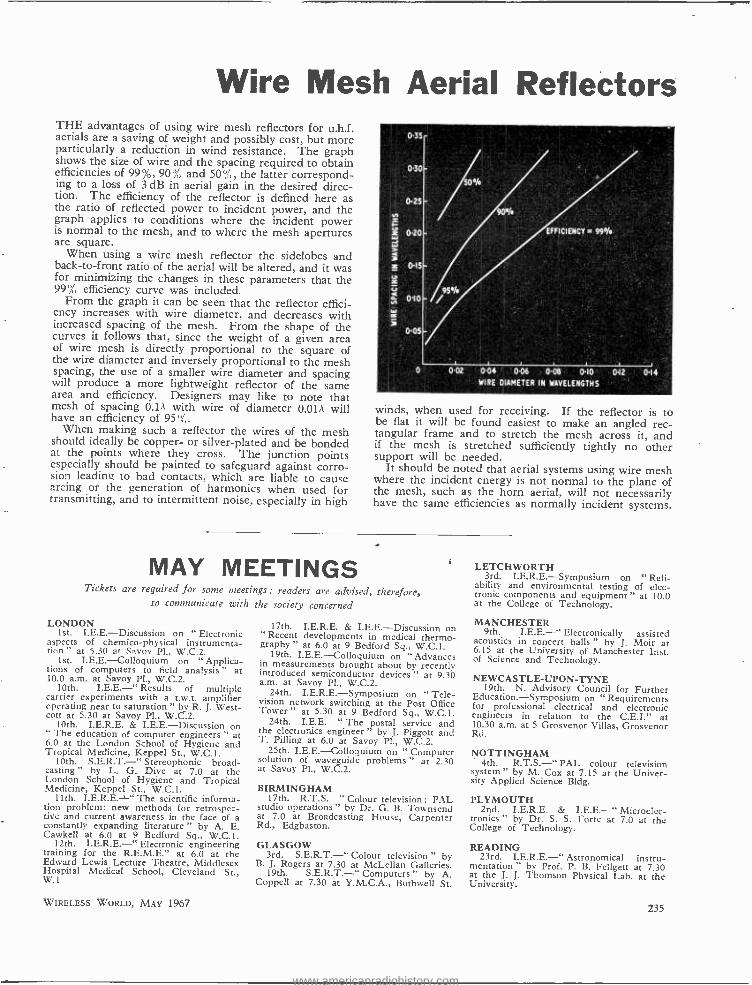
Wire Mesh Aerial Reflectors THE advantages of using wire mesh reflectors for u.h.f. aerials are a saving of weight and possibly cost, but more particularly a reduction in wind resistance. The graph shows the size of wire and the spacing required to obtain efficiencies of 99 %, 90 % and 50%, , the latter correspond- ing to a loss of 3 dB in aerial gain in the desired direc- tion. The efficiency of the reflector is defined here as the ratio of reflected power to incident power, and the graph applies to conditions where the incident power is normal to the mesh, and to where the mesh apertures are square.
When using a wire mesh reflector the sidelobes and back -to -front ratio of the aerial will be altered, and it was for minimizing the changes in these parameters that the 99% efficiency curve was included.
From the graph it can be seen that the reflector effici- ency increases with wire diameter, and decreases with increased spacing of the mesh. From the shape of the curves it follows that, since the weight of a given area of wire mesh is directly proportional to the square of the wire diameter and inversely proportional to the mesh spacing, the use of a smaller wire diameter and spacing will produce a more lightweight reflector of the same area and efficiency. Designers may like to note that mesh of spacing O.1A with wire of diameter O.OIA will have an efficiency of 95 %.
When making such a reflector the wires of the mesh should ideally be copper- or silver -plated and be bonded at the points where they cross. The junction points especially should be painted to safeguard against corro- sion leading to bad contacts, which are liable to cause arcing or the generation of harmonics when used for transmitting, and to intermittent noise, especially in high
MAY MEETINGS
0.35
030
0.25
0.20
015
010
005
EFFICIENCY= 991/4
95%
0 0.02 0.04 0-06 0.08 0.10 012 0.14 WIRE DIAMETER IN WAVELENGTHS
winds, when used for receiving. If the reflector is to be flat it will be found easiest to make an angled rec- tangular frame and to stretch the mesh across it, and if the mesh is stretched sufficiently tightly no other support will be needed.
It should be noted that aerial systems using wire mesh where the incident energy is not normal to the plane of the mesh, such as the horn aerial, will not necessarily have the same efficiencies as normally incident systems.
Tickets are required for some meetings : readers are advised, therefore, to communicate with the society concerned
LONDON 1st. I.E.E. -Discussion on " Electronic
aspects of chemico- physical instrumenta- tion " at 5.30 at Savoy Pl., W.C.2.
1st. I.E.E. -Colloquium on " Applica- tions of computers to field analysis " at 10.0 a.m. at Savoy Pl., W.C.2.
10th. LE.E. -" Results of multiple carrier experiments with a t.w.t. amplifier operating near to saturation " by R. J. West- con at 5.30 at Savoy Pl., W.C.2.
10th. I.E.R.E. & I.E.E. -Discussion on " The education of computer engineers " at 6.0 at the London School of Hygiene and Tropical Medicine, Keppel St., W.C.1.
10th. S.E.R.T. -" Stereophonic broad- casting " by L. G. Dive at 7.0 at the London School of Hygiene and Tropical Medicine, Keppel St., W.C.1.
11th. The scientific informa- tion problem: new methods for retrospec- tive and current awareness in the face of a constantly expanding literature " by A. E. Cawkell at 6.0 at 9 Bedford Sq., W.C.1.
12th. I.E.R.E.-" Electronic engineering training for the R.E.M.E." at 6.0 at the Edward Lewis Lecture Theatre, Middlesex Hospital Medical School, Cleveland St., W.1
WIRELESS WORLD, MAY 1967
17th. I.E.R.E. & I.E.E.- Discussion on " Recent developments in medical thermo- graphy " at 6.0 at 9 Bedford Sq., W.C.1.
19th. I.E.E. -Colloquium on " Advances in measurements brought about by recently introduced semiconductor devices " at 9.30 a.m. at Savoy Pl., W.C.2.
24th. I.E.R.E.- Symposium on " Tele- vision network switching at the Post Office Tower " at 5.30 at 9 Bedford Sq., W.C.1.
24th. I.E.E. " The postal service and the electronics engineer " by J. Piggott and T. Pilling at 6.0 at Savoy Pl., W.C.2.
25th. I.E.E. -Colloquium on " Computer solution of waveguide problems " at 2.30 at Savoy Pl., W.C.2.
BIRMINGHAM 17th. R.T.S. " Colour television : PAL
studio operations " by Dr. G. B. Townsend at 7.0 at Broadcasting House, Carpenter Rd., Edgbaston.
GLASGOW 3rd. S.E.R.T. -" Colour television " by
B. J. Rogers at 7.30 at McLellan Galleries. 19th. S.E.R.T.-" Computers " by A.
Coppell at 7.30 at Y.M.C.A., Bothwell St.
LETCHWORTH 3rd. I.E.R.E.- Symposium on "Reli-
ability and environmental testing of elec- tronic components and equipment " at 10.0 at the College of Technology.
MANCHESTER 9th. I.E.E. -" Electronically assisted
acoustics in concert halls " by J. Moir at 6.15 at the University of Manchester Inst. of Science and Technology.
NEWCASTLE -UPON -TYNE 19th. N. Advisory Council for Further
Education.- Symposium on " Requirements for professional electrical and electronic engineers in relation to the C.E.I." at 10.30 a.m. at 5 Grosvenor Villas, Grosvenor Rd.
NOTTINGHAM 4th. R.T.S. -" PAL colour television
system " by M. Cox at 7.15 at the Univer- sity Applied Science Bldg.
PLYMOUTH 2nd. I.E.R.E. & I.E.E. -" Microelec-
tronics " by Dr. S. S. Forte at 7.0 at the College of Technology.
READING 23rd. I.E.R.E. -" Astronomical instru-
mentation " by Prof. P. B. Feilgett at 7.30 at the J. J. Thomson Physical Lab. at the University.
235
www.americanradiohistory.com
Paris Components Show
FRENCH RIVAL TO SHADOW -MASK TUBE
New Devices seen at the Salon International des Composants Electroniques
TWO branches of electronic tech- nology of special importance in Europe at the moment are colour
television and integrated circuits and at the recent Paris Components Show (Porte de Versailles, 5 -10 April) there was evidence of rapid development in both these fields. The French com- ponent manufacturers, who domin- ated the exhibition numerically, are particularly concerned about both of them -colour because a regular colour television service on the French 625 -line second network using the SECAM system is due to start in October, and integrated circuits because French government policy on technology has recently en- couraged a massive invasion of American semiconductor and i.c.
manufacturers into the country. Since U.S. semiconductor technology is two or three years ahead of Europe's, the native French manufacturers are find- ing it difficult to compete with the subsidiaries of the American corn - panies, and there are fears for the future of this sector of the industry. On the other hand, SECAM colour TV is seen as a big opportunity for French component manufacturers to develop their own products and find good markets for them -particularly as the French have extensive technical and commercial agreements with Russia and the eastern bloc countries, to whom they have " sold " the SECAM system.
To meet the commercial threat from U.S. manufacturers of integrated circuits, the French government is
now considering the possibility of instituting a national plan for elec- tronic components, a " Plan Compos- ants." In this the big French semi- conductor and integrated circuit com- panies would join forces and organize a massive national effort to develop really advance devices, largely sup-. ported by French money. This might well follow the pattern of a similar scheme, a " Plan Calcul " already put into operation for the protection of the French computer industry.
Many of the colour receiver com- ponents on show- shadow -mask dis- play tubes, deflection and convergence coils, scanning valves, line- output transformers, etc. -were very similar
236
to those which arc becoming familiar in the U.K. But a somewhat different approach in set design -in particular more complete transistorization -may well become possible as a result of a new type of tri- colour display tube which has just been introduced by the Compagnie Francaise de Télévision (who developed SECAM). This has the usual three electron guns, but the shadow mask is replaced by a grid of 550 vertical wires with 0.75 mm spac- ing, and the RGB phosphor dots on the screen by vertical RGB phosphor stripes- actually 480 triplets. Coated on the back of the phosphor screen are films of aluminium and graphite. The wire grid, to which a potential of 7 kV is applied, separates the beams, and, in conjunction with the screen, which is at an e.h.t. of 25 kV, focuses them on to the appropriate phosphor stripes. Post -acceleration of the beam electrons occurs between this grid and the screen. This separation system is claimed to have an electron transpar- ency as high as 80 -90 %, whereas a shadow mask allows only about 20 %,
of the electrons through to the screen. As a result, for a given screen bright- ness, the beam modulation signals can be much smaller than those re- quired by the shadow -mask tube, and, because of the post- acceleration, the energy needed for beam deflection is less. The big advantage of these two characteristics is that the new tube can be modulated and deflected with- out difficulty by transistor circuits. Line scanning on 625 lines requires about 11 watts and field scanning about 4 watts. Static and dynamic convergence is still needed, however. Manufacture is said to be simpler than with the shadow -mask tube.
Transistors, of course, are already being used for modulation and deflec- tion in the smaller black -and -white television receivers. An example of a completely transistorized set was shown by the French company Orega to demonstrate the possibilities of their television components. An interesting feature of this " lash -up " was a new Orega u.h.f. /v.h.f. tuner with no moving parts -capacitance variation for tuning is achieved by applying d.c. voltages across varicap diodes and band -changing by means
of switching diodes. The tuner, which has a gain of 25 dB and a noise factor of 7 dB, uses four transistors, five varicap diodes and nine switching diodes. Tuning voltages are applied from potentiometer networks, using pre -selection push buttons incorpor- ating variable controls. The tuner was also demonstrated in operation on a lash -up 625/819 -line colour re- ceiver, along with a range of colour TV components and sub -assemblies.
Among the British exhibitors, Plessey were showing a complete set of colour scanning wound components for use with 90° tubes. The line out- put transformer is interesting in that it does not have the usual type of e.h.t. secondary winding. The trans- former secondary produces about 7 kV and this is brought up to the required 25 kV by a voltage multiplier using selenium rectifier sticks.
A range of germanium power tran- sistors intended for line scanning out- put stages was presented by the Italian company Ates Componenti Elettronici. One, the latest, for SECAM colour receivers, is the AT450, which has maximum ratings of 430 V collector -to -base, 150 V col - lector-to- emitter, and 10 A collector current. The company also showed a complete line- output /e.h.t. sub- assembly for a 23 -in, 114° portable receiver using their AU112 ger- manium power transistor. With a supply of 40 V, this generates 260 V at the primary of the output trans- former and produces an e.h.t. of 18 kV.
Another new field into which power transistors are beginning to penetrate, is amplification of signals in the Gc /s region. Both R.C.A. and TRW Semi- conductors had types capable of delivering 1 W at 2 Gc /s with a gain of 5 dB. The TRW transistor (2N4976) is constructed for incorpora- tion in strip -line circuits and the R.C.A. one (TA7003) for incorpora- tion in coaxial circuits.
It was interesting to see hints of the possibility of obtaining useful amounts of power from linear inte- grated circuits. LCC- STEAFIX, of France, had an integrated servo amplifier with an output of 3.5 W, while R.C.A. showed a range of linear
WIRELESS WORLD, MAY 1967
www.americanradiohistory.com
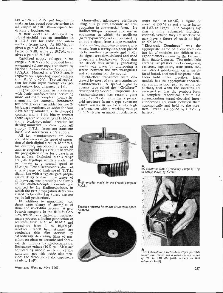
i.cs which could be put together to make an f.m. sound receiver giving an a.f. output of 550 mW- adequate for driving a loudspeaker.
A new linear i.c. displayed by SGS- Fairchild was an amplifier in a TO -5 can for radio and inter- mediate frequencies. At 100 Mc /s it gives a gain of 20 dB and has a noise factor of 7 dB, while at 10.7 Mc /s it gives a gain of 26.5 dB.
Stabilized supply voltages in the range 2 to 30 V can be provided by an integrated voltage regulator shown by National Semiconductor Corporation (U.S.A.). Housed in a TO -5 can, it requires corresponding input voltages from 8.5 V to 40 V. Typical regula- tion for both input voltage changes and output load changes, is 1 %,.
Digital i.cs continue to proliferate, with logic configurations becoming more and more complex. Texas In- struments, for example, introduced five new devices : an adder for two 2- bit binary numbers, an adder for four 2 -bit binary numbers, a divide -by -12 counter and a 4-bit binary counter (both capable of operating at 15 Mc /s), and a b.c.d.- to- decimal decoder for driving numerical indicator tubes. All employ T.T.L. (transistor -transistor logic) and work from a 5 V supply.
All i.c. manufacturers are con- cerned to increase the speed of opera-. tion of their digital circuits. Motorola, for example, introduced a range of emitter -coupled logic circuits in which the propagation delay for a gate is as low as 5 ns. Included in this range are J -K flip -flops which are claimed to operate at a typical speed of 85 Mc /s. Texas Instruments also had a new range of high -speed T.T.L. digital i.cs with a typical gate propa- gation delay of 6ns. The fastest of all, however, was probably the family of six emitter -coupled circuits an- nounced by La Radiotechnique, in which the gate propagation delay was stated to be only 2 ns (these are not yet in full production).
In addition to monolithic i.c.s. there were plenty of examples of thin- and thick -film circuits. A new French company in the field is Cer- mex, which has a thick -film manufac- turing process allowing production of resistors from 1012 to 10 MS2 and capacitors from 1 to 10,000 pF. Another French firm, Alcatel, are producing thin film devices by cathodicaUp depositing films of tan- talum on glass or ceramic and form- ing the circuits by photoengraving. Resistance values (10 S2 to 1 Mfg) are adjusted by anodic oxidation of the tantalum, and this oxide also pro- vides the dielectric of the capacitors (2 nF to 1µF).
WIRELESS WORLD, MAY 1967
Gunn -effect microwave oscillators using bulk gallium arsenide are now appearing in commercial form. La Radiotechnique demonstrated one in equipment in which the oscillator (battery- powered) was modulated by an audio signal from a tape recorder. The resulting microwaves were trans- mitted from a waveguide, then picked up by another waveguide and finally the signal was demodulated and used to operate a loudspeaker. Proof that the device was actually generating waves was given by interposing a screen between the two waveguides and so cutting off the sound.
Field -effect transistors were dis- played by most of the semiconductor manufacturers. A special high -fre- quency type called the " Gridistor " developed by Société Européenne des Semiconducteurs has recently gone into production. This has a p -type grid structure in an n -type substrate which results in an extremely high performance: with a working voltage of 50 V. It has an imput impedance of
t Shaft encoder made by the French company M.C.B.
Thomson Houston -Hotchkiss Brandt four -speed turntable. y
more than 10,000 M1?, a figure of merit of 150 Mc /s and a noise factor of 1 dB at 1 kc /s. The company say that a more advanced, multiple - channel, version they are working on may have a figure of merit as high as 500 Mc/s. " Electronic Dominoes " was the appropriate name of a circuit- build- ing kit of modules for children and experimenters shown by the German firm, Egger -Lectron. The units, little rectangular plastics blocks containing resistors, capacitors, transistors, etc., are placed side -by -side on a metal - faced board, and small magnets inside them hold them together. Each module has the appropriate theoreti- cal circuit symbol printed on its top surface, and when the modules are arranged so that the symbols form a complete theoretical circuit the corresponding actual electrical inter- connections are made between them automatically and held by the mag- nets. Power is supplied by a 9 V dry battery.
RC oscillator with a frequency range of I c's to IMc /s shown by Alcatel.
This Laboratoire Electro- Acoustique portable sound level meter has a measurement range of 24 to 140 dB (with respect to 0dB reference level).
237
www.americanradiohistory.com
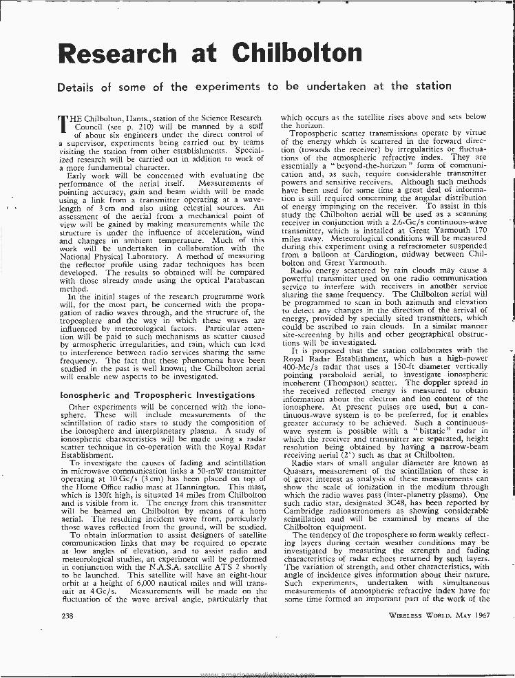
Research at Chilbolton Details of sonne of the experiments to be undertaken at the station
THE Chilbolton, Hants., station of the Science Research Council (see p. 210) will be manned by a staff of about six engineers under the direct control of
a supervisor, experiments being carried out by teams visiting the station from other establishments. Special- ized research will be carried out in addition to work of a more fundamental character.
Early work will be concerned with evaluating the performance of the aerial itself. Measurements of pointing accuracy, gain and beam width will be made using a link from a transmitter operating at a wave- length of 3 cm and also using celestial sources. An assessment of the aerial from a mechanical point of view will be gained by making measurements while the structure is under the influence of acceleration, wind and changes in ambient temperature. Much of this work will be undertaken in collaboration with the National Physical Laboratory. A method of measuring the reflector profile using radar techniques has been developed. The results so obtained will be compared with those already made using the optical Parabascan method.
In the initial stages of the research programme work will, for the most part, be concerned with the propa- gation of radio waves through, and the structure of, the troposphere and the way in which these waves are influenced by meteorological factors. Particular atten- tion will be paid to such mechanisms as scatter caused by atmospheric irregularities, and rain, which can lead to interference between radio services sharing the same frequency. The fact that these phenomena have been studied in the past is well known; the Chilbolton aerial will enable new aspects to be investigated.
Ionospheric and Tropospheric Investigations Other experiments will be concerned with the iono-
sphere. These will include measurements of the scintillation of radio stars to study the composition of the ionosphere and interplanetary plasma. A study of ionospheric characteristics will be made using a radar scatter technique in co- operation with the Royal Radar Establishment.
To investigate the causes of fading and scintillation in microwave communication links a 50 -mW transmitter operating at 10 Gc /s (3 cm) has been placed on top of the Home Office radio mast at Hannington. This mast, which is 130ft high, is situated 14 miles from Chilbolton and is visible from it. The energy from this transmitter will be beamed en Chilbolton by means of a horn aerial. The resulting incident wave front, particularly those waves reflected from the ground, will be studied.
To obtain information to assist designers of satellite communication links that may be required to operate at low angles of elevation, and to assist radio and meteorological studies, an experiment will be performed in conjunction with the N.A.S.A. satellite ATS 2 shortly to be launched. This satellite will have an eight -hour orbit at a height of 6,000 nautical miles and will trans- mit at 4Gc /s. Measurements will be made on the fluctuation of the wave arrival angle, particularly that
238
which occurs as the satellite rises above and sets below the horizon.
Tropospheric scatter transmissions operate by virtue of the energy which is scattered in the forward direc- tion (towards the receiver) by irregularities or fluctua- tions of the atmospheric refractive index. They are essentially a "beyond -the- horizon" form of communi- cation and, as such, require considerable transmitter powers and sensitive receivers. Although such methods have been used for some time a great deal of informa- tion is still required concerning the angular distribution of energy impinging on the receiver. To assist in this study the Chilbolton aerial will be used as a scanning receiver in conjunction with a 2.6 -Gc /s continuous -wave transmitter, which is installed at Great Yarmouth 170 miles away. Meteorological conditions will be measured during this experiment using a refractometer suspended from a balloon at Cardington, midway between Chil- bolton and Great Yarmouth.
Radio energy scattered by rain clouds may cause a powerful transmitter used on one radio communication service to interfere with receivers in another service sharing the same frequency. The Chilbolton aerial will be programmed to scan in both azimuth and elevation to detect any changes in the direction of the arrival of energy, provided by specially sited transmitters, which could be ascribed to rain clouds. In a similar manner site -screening by hills and other geographical obstruc- tions will be investigated.
It is proposed that the station collaborates with the Royal Radar Establishment, which has a high -power 400 -Mc /s radar that uses a 150 -ft diameter vertically pointing paraboloid aerial, to investigate ionospheric incoherent (Thompson) scatter. The doppler spread in the received reflected energy is measured to obtain information about the electron and ion content of the ionosphere. At present pulses are used, but a con- tinuous -wave system is to be preferred, for it enables greater accuracy to be achieved. Such a continuous- wave system is possible with a "bistatic" radar in which the receiver and transmitter are separated, height resolution being obtained by having a narrow -beam receiving aerial (2`) such as that at Chilbolton.
Radio stars of small angular diameter are known as Quasars, measurement of the scintillation of these is of great interest as analysis of these measurements can show the scale of ionization in the medium through which the radio waves pass (inter -planetry plasma). One such radio star, designated 3C48, has been reported by Cambridge radioastronomers as showing considerable scintillation and will be examined by means of the Chilbolton equipment.
The tendency of the troposphere to form weakly reflect- ing layers during certain weather conditions may be investigated by measuring the strength and fading characteristics of radar echoes returned by such layers. The variation of strength, and other characteristics, with angle of incidence gives information about their nature. Such experiments, undertaken with simultaneous measurements of atmospheric refractive index have for some time formed an important part of the work of the
WIRELESS WORLD, MAY 1967
www.americanradiohistory.com
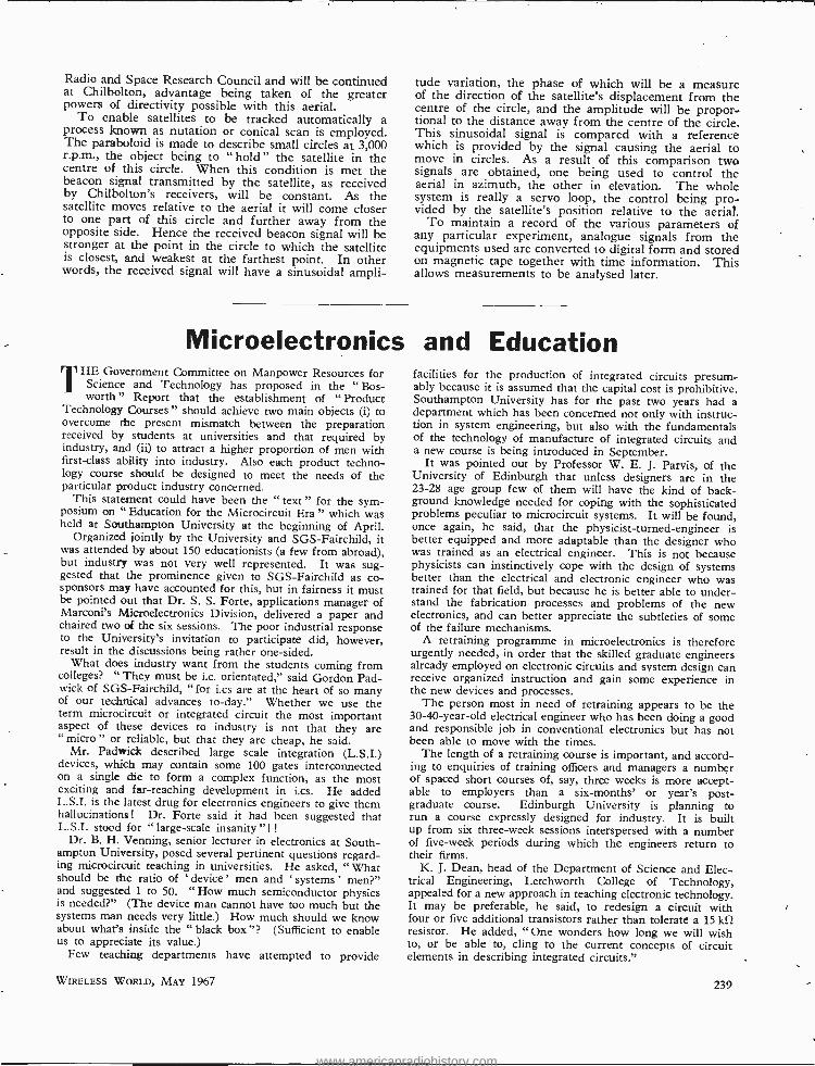
Radio and Space Research Council and will be continued at Chilbolton, advantage being taken of the greater powers of directivity possible with this aerial.
To enable satellites to be tracked automatically a process known as nutation or conical scan is employed. The paraboloid is made to describe small circles at 3,000 r.p.m., the object being to " hold " the satellite in the centre of this circle. When this condition is met the beacon signal transmitted by the satellite, as received by Chilbolton's receivers, will be constant. As the satellite moves relative to the aerial it will come closer to one part of this circle and further away from the opposite side. Hence the received beacon signal will be stronger at the point in the circle to which the satellite is closest, and weakest at the farthest point. In other words, the received signal will have a sinusoidal ampli-
tude variation, the phase of which will be a measure of the direction of the satellite's displacement from the centre of the circle, and the amplitude will be propor- tional to the distance away from the centre of the circle. This sinusoidal signal is compared with a reference which is provided by the signal causing the aerial to move in circles. As a result of this comparison two signals are obtained, one being used to control the aerial in azimuth, the other in elevation. The whole system is really a servo loop, the control being pro- vided by the satellite's position relative to the aerial.
To maintain a record of the various parameters of any particular experiment, analogue signals from the equipments used are converted to digital form and stored on magnetic tape together with time information. This allows measurements to be analysed later.
Microelectronics and Education THE Government Committee on Manpower Resources for
Science and Technology has proposed in the " Bos- worth " Report that the establishment of "Product
Technology Courses " should achieve two main objects (i) to overcome the present mismatch between the preparation received by students at universities and that required by industry, and (ii) to attract a higher proportion of men with first -class ability into industry. Also each product techno- logy course should be designed to meet the needs of the particular product industry concerned.
This statement could have been the " text " for the sym- posium on " Education for the Microcircuit Era " which was held at Southampton University at the beginning of April.
Organized jointly by the University and SGS- Fairchild, it was attended by about 150 educationists (a few from abroad), but industry was not very well represented. It was sug- gested that the prominence given to SGS -Fairchild as co- sponsors may have accounted for this, but in fairness it must be pointed out that Dr. S. S. Forte, applications manager of Marconi's Microelectronics Division, delivered a paper and chaired two of the six sessions. The poor industrial response to the University's invitation to participate did, however, result in the discussions being rather one -sided.
What does industry want from the students coming from colleges? " They must be i.c. orientated," said Gordon Pad - wick of SGS -Fairchild, "for i.cs are at the heart of so many of our technical advances to- day." Whether we use the term microcircuit or integrated circuit the most important aspect of these devices to industry is not that they are " micro " or reliable, but that they are cheap, he said.
Mr. Padwick described large scale integration (L.S.I.) devices, which may contain some 100 gates interconnected on a single be to form a complex function, as the most exciting and far -reaching development in i.cs. He added L.S.I. is the latest drug for electronics engineers to give them hallucinations! Dr. Forte said it had been suggested that L.S.I. stood for " large -scale insanity "! !
Dr. B. H. Venning, senior lecturer in electronics at South- ampton University, posed several pertinent questions regard- ing microcircuit teaching in universities. He asked, " What should be the ratio of `device' men and `systems' men ?" and suggested 1 to 50. "How much semiconductor physics is needed?" (The device man cannot have too much but the systems man needs very little.) How much should we know about what's inside the " black box "? (Sufficient to enable us to appreciate its value.)
Few teaching departments have attempted to provide
WIRELESS WORLD, MAY 1967
facilities for the production of integrated circuits presum- ably because it is assumed that the capital cost is prohibitive. Southampton University has for the past two years had a department which has been concerned not only with instruc- tion in system engineering, but also with the fundamentals of the technology of manufacture of integrated circuits and a new course is being introduced in September.
It was pointed out by Professor W. E. J. Parvis, of the University of Edinburgh that unless designers are in the 23 -28 age group few of them will have the kind of back- ground knowledge needed for coping with the sophisticated problems peculiar to microcircuit systems. It will be found, once again, he said, that the physicist- turned -engineer is better equipped and more adaptable than the designer who was trained as an electrical engineer. This is not because physicists can instinctively cope with the design of systems better than the electrical and electronic engineer who was trained for that field, but because he is better able to under- stand the fabrication processes and problems of the new electronics, and can better appreciate the subtleties of some of the failure mechanisms.
A retraining programme in microelectronics is therefore urgently needed, in order that the skilled graduate engineers already employed on electronic circuits and system design can receive organized instruction and gain some experience in the new devices and processes.
The person most in need of retraining appears to be the 30 -40- year -old electrical engineer who has been doing a good and responsible job in conventional electronics but has not been able to move with the times.
The length of a retraining course is important, and accord- ing to enquiries of training officers and managers a number of spaced short courses of, say, three weeks is more accept- able to employers than a six- months' or year's post- graduate course. Edinburgh University is planning to run a course expressly designed for industry. It is built up from six three -week sessions interspersed with a number of five -week periods during which the engineers return to their firms.
K. J. Dean, head of the Department of Science and Elec- trical Engineering, Letchworth College of Technology, appealed for a new approach in teaching electronic technology. It may be preferable, he said, to redesign a circuit with four or five additional transistors rather than tolerate a 15 kit resistor. He added, " One wonders how long we will wish to, or be able to, cling to the current concepts of circuit elements in describing integrated circuits."
239
www.americanradiohistory.com
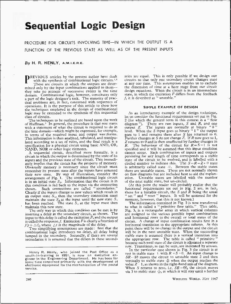
Sequential Logic Design
PROCEDURE FOR CIRCUITS INVOLVING TIME -IN WHICH THE OUTPUT IS A
FUNCTION OF THE PREVIOUS STATE AS WELL AS OF THE PRESENT INPUTS
By H. R. HENLY. A.m.I.E.R.E.
PREVIOUS articles by the present author have dealt with the synthesis of combinational logic circuits.'2 These are circuits in which the outputs are deter-
mined only by the input combinations applied to them - they take no account of successive events in the time domain. Combinational logic, however, constitutes only a part of the logic designer's task. The majority of prac- tical problems are, in fact, concerned with sequences of operations. It is the purpose of this article to show how the techniques employed in the design of combinational logic may be extended to the synthesis of this sequential class of circuits.
The techniques to be outlined are based upon the work of Huffman.3 In general, the procedure is that one starts with a statement of what the circuit is required to do in the time domain -which might be expressed, for example, in terms of the required input and output waveforms. This information is then analysed, tabulated, and manipu- lated according to a set of rules, and the final result is a specification for a physical circuit using basic AND, OR, NAND, NOR or other logic elements.
A sequential circuit, described more formally, is a circuit in which the output is determined by the state of its inputs and the previous state of the circuit. This immedi- ately implies that the circuit has the property of memory. Obviously memory is necessary since the circuit must remember its present state after the inputs have assumed their new state. By way of illustration, consider the arrangement of Fig. 1. The combinational logic circuit is in an initial state So. Information that the circuit is in this condition is fed back to the input via the connection shown. Such connections are called " secondaries." Clearly if the inputs change to new values which result in an output state S1, then the secondary connection must maintain the state So at the input until the new state S1 has been reached. The state S1 at the input must then maintain this new state.
The only way in which this condition can be met is by inserting a delay in the secondary circuit, as shown. The input to this delay is called the excitation F, and the output is called the response, f. Excitation F is clearly a function of f (t + A t), where A t is the magnitude of the delay.
Two simplifying assumptions are made: first that the combinational logic introduces no delay, all delay being lumped in the secondary. Secondly, if there are several secondaries it is assumed that the delays in these second-
Henry R. Henly, who joined the Post Office as a youth -in- training in 1951, is now an executive en- gineer in the Engineering Department. He has been for some time concerned primarily with the development of electronic equipment for the mechanization of the postal service.
aries are equal. This is only possible if we design our circuits so that only one secondary circuit changes state at any one time. This assumption enables us to exclude the dimension of time at a later stage from our circuit design equations. When the circuit is in an intermediate state, in which the excitation F differs from the feedback f, it is described as " unstable."
SIMPLE EXAMPLE OF DESIGN
As an introductory example of the design technique, let us consider the functional requirements set out in Fig. 2 (for which the general term in this context is a " flow diagram "). There are two inputs, S and R, and one output Z. The inputs are normally at binary " 0 " level. When the S input goes to binary " 1 " the output goes to 1 and remains there after S has returned to O. Further changes at S do not change Z. If R now goes to 1, Z returns to 0 and is then unaffected by further changes in R. The behaviour of the circuit for R=S =1 is not specified and it will be assumed that this input condition cannot occur. Each combination of inputs and outputs persisting for any length of time corresponds to a stable state of the circuit to be evolved, and is labelled with a circled number to indicate this. The S =R =Z - 0 state is arbitrarily called state (t). Between the stable states there are unstable states. These are not normally shown on flow diagrams but are included here to aid the explan- ation. Unstable states are labelled with the number of the next stable state, but un- circled.
(At this point the reader will probably realize that the functional requirements set out in Fig. 2 are, in fact, those for a bistable circuit, the S and R being the usual " set " and " reset " inputs. It will be assumed for the moment, however, that this is not known.)
The information contained in Fig. 2 is now transferred to what is called a " primitive flow table." This table, Fig. 3, is a rectangular array in which vertical columns are assigned to the various possible input combinations and horizontal rows to the overall or total states of the circuit. A change of input combination results first in a horizontal transistion to the appropriate column. At this point there will be no change in the output and the circuit will be in the next unstable state. When the succeeding stable state is assumed there is a vertical transition into the appropriate row. The table is called " primitive " because each total state of the circuit is allocated a separate row. Transitions, as can be seen, are indicated by arrows.
In the particular case shown in Fig. 3 the circuit is at rest in stable state i with R- S - O. An input change to SR =10 moves the circuit to unstable state 2 and then vertically to stable state 2 when the output reaches the value Z =1, as shown in the right -hand axis of the diagram. When S returns to zero, i.e. SR =00, the circuit moves via 3 to stable state 3 ), at which it will stay until a further
240 WIRELESS WORLD, MAY 1967
www.americanradiohistory.com
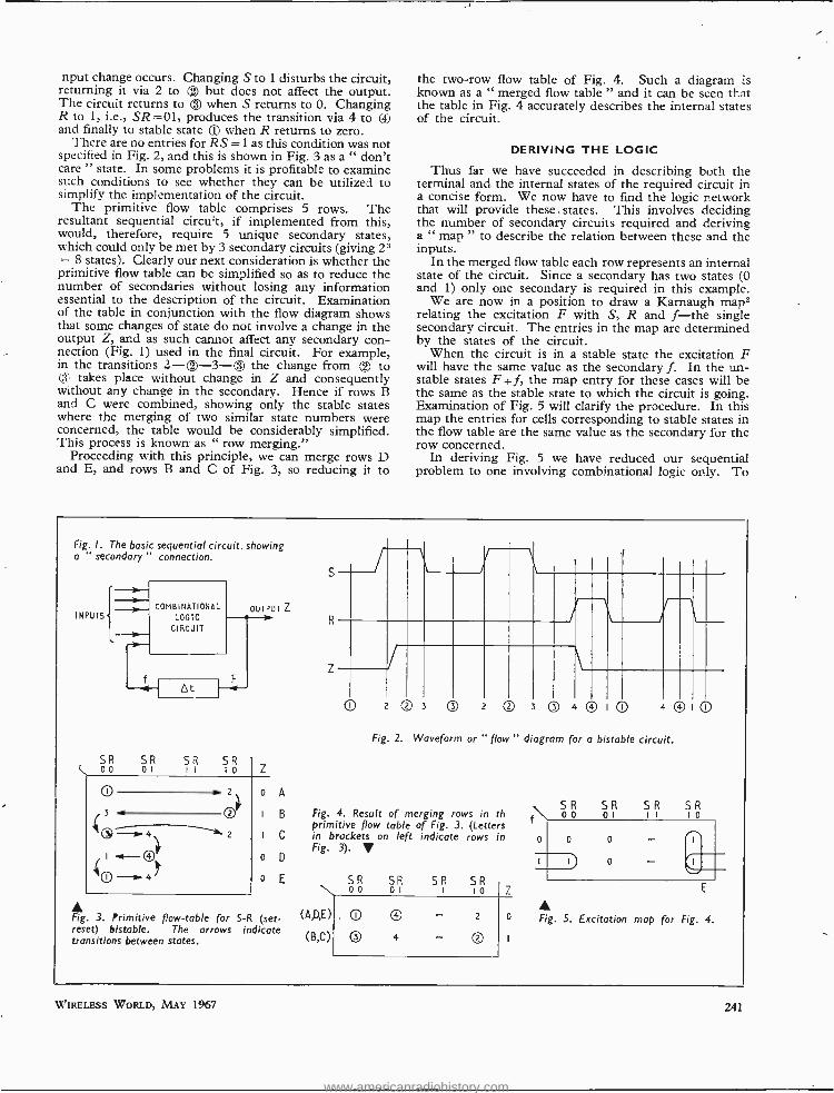
nput change occurs. Changing S to 1 disturbs the circuit, returning it via 2 to Q2 but does not affect the output. The circuit returns to Q3 when S returns to O. Changing R to 1, i.e., SR =01, produces the transition via 4 to and finally to stable state t3l when R returns to zero.
There are no entries for RS =1 as this condition was not specified in Fig. 2, and this is shown in Fig. 3 as a " don't care " state. In some problems it is profitable to examine such conditions to see whether they can be utilized to simplify the implementation of the circuit.
The primitive flow table comprises 5 rows. The resultant sequential circuit, if implemented from this, would, therefore, require 5 unique secondary states, which could only be met by 3 secondary circuits (giving 2' = 8 states). Clearly our next consideration is whether the primitive flow table can be simplified so as to reduce the number of secondaries without losing any information essential to the description of the circuit. Examination of the table in conjunction with the flow diagram shows that some changes of state do not involve a change in the output Z, and as such cannot affect any secondary con- nection (Fig. 1) used in the final circuit. For example, in the transitions 2- ® -3-(:® the change from e to
3 takes place without change in Z and consequently without any change in the secondary. Hence if rows B and C were combined, showing only the stable states where the merging of two similar state numbers were concerned, the table would be considerably simplified. This process is known as " row merging."
Proceeding with this principle, we can merge rows D and E, and rows B and C of Fig. 3, so reducing it to
the two -row flow table of Fig. 4. Such a diagram is known as a " merged flow table " and it can be seen that the table in Fig. 4 accurately describes the internal states of the circuit.
DERIVING THE LOGIC
Thus far we have succeeded in describing both the terminal and. the internal states of the required circuit in a concise form. We now have to find the logic network that will provide these , states. This involves deciding the number of secondary circuits required and deriving a " map " to describe the relation between these and the inputs.
In the merged flow table each row represents an internal state of the circuit. Since a secondary has two states (0 and 1) only one secondary is required in this example.
We are now in a position to draw a Karnaugh map2 relating the excitation F with S, R and f -the single secondary circuit. The entries in the map are determined by the states of the circuit.
When the circuit is in a stable state the excitation F will have the same value as the secondary f. In the un- stable states F $ f, the map entry for these cases will be the same as the stable state to which the circuit is going. Examination of Fig. 5 will clarify the procedure. In this map the entries for cells corresponding to stable states in the flow table are the same value as the secondary for the row concerned.
In deriving Fig. 5 we have reduced our sequential problem to one involving combinational logic only. To
Fig. I. The basic sequential circuit, showing a " secondary " connection.
INPUTS
11.
COMBINATIONAL LOGIC
CIRCUIT
At
OUTPUT Z
< 00 R SR SR
Z
O zl
OOI
2
o A
B
I C
o D
o E
s
(3 .011
Q->4 I
®Z o-.f4".
Fig. 3. Primitive flow -table for S -R (set - reset) bistable. The arrows indicate transitions between states.
S
R
0 O 3 O 02 3 0 4® O 4 ® O
Fig. 2. Waveform or " flow " diagram for a bistable circuit.
Fig. 4. Result of merging rows in th primitive flow table of Fig. 3. (Letters in brackets on left indicate rows in Fig. 3). V
SR \ ao
(A,D,E )
(B,C)
O
SR o SR SR I 10 Z
4
- 2
O
o
SR SR SR SR oo 01 I I I o
Fig. 5. Excitation map for Fig. 4.
\W'IRELESS WORLD, MAY 1967 241
www.americanradiohistory.com
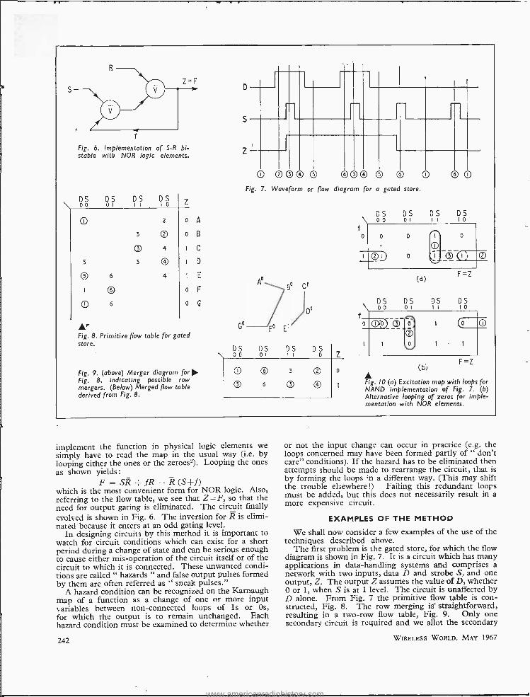
f
Fig. 6. Implementation of S -R bi- stable with NOR logic elements.
\ óó DS DS DS
Z
0 3
z
02
o A
o B
O 4 C
5 3 ® I D
I
O
6
© 6
4 I E
o F
o
Fig. 8. Primitive flow table for gated store.
Fig. 9. (above) Merger diagram for O. Fig. 8, indicating possible row mergers. (Below) Merged flow table derived from Fig. 8.
D
5
Z
0 00® 0 ® ®® ® © 0 Fig. 7. Waveform or flow diagram for a gated store.
DS 00
C
DS DS DS o l 1 1 l o
05 6 03
0
DS \ 00 f
f
DS 0 DS
O 0
DS I o
O
F=Z
DS i0
O
F =Z
DS 00
DS 01
(d)
DS II
o o
(bi
Fig. IO (a) Excitation map with loops for NAND implementation of Fig. 7. (b) Alternative looping of zeros for imple- mentation with NOR elements.
implement the function in physical logic elements we simply have to read the map in the usual way (i.e. by looping either the ones or the zeroes2). Looping the ones as shown yields:
F= SR -{-fR (S+ f) which is the most convenient form for NOR logic. Also, referring to the flow table, we see that Z = F, so that the need for output gating is eliminated. The circuit finally evolved is shown in Fig. 6. The inversion for R is elimi- nated because it enters at an odd gating level.
In designing circuits by this method it is important to watch for circuit conditions which can exist for a short period during a change of state and can be serious enough to cause either mis- operation of the circuit itself or of the circuit to which it is connected. These unwanted condi- tions are called " hazards " and false output pulses formed by them are often referred as " sneak pulses."
A hazard condition can be recognized on the Karnaugh map of a function as a change of one or more input variables between non -connected loops of is or Os,
for which the output is to remain unchanged. Each hazard condition must be examined to determine whether
242
or not the input change can occur in practice (e.g. the loops concerned may have been formed partly of " don't care" conditions). If the hazard has to be eliminated then attempts should be made to rearrange the circuit, that is by forming the loops ;n a different way. (This may shift the trouble elsewhere!) Failing this redundant loops must be added, but this does not necessarily result in a more expensive circuit.
EXAMPLES OF THE METHOD
We shall now consider a few examples of the use of the techniques described above.
The first problem is the gated store, for which the flow diagram is shown in Fig. 7. It is a circuit which has many applications in data -handling systems and comprises a network with two inputs, data D and strobe S, and one output, Z. The output Z assumes the value of D, whether 0 or 1, when S is at 1 level. The circuit is unaffected by D alone. From Fig. 7 the primitive flow table is con- structed, Fig. 8. The row merging is straightforward, resulting in a two -row flow table, Fig. 9. Only one secondary circuit is required and we allot the secondary
WIRELESS WORLD, MAY 1967
www.americanradiohistory.com
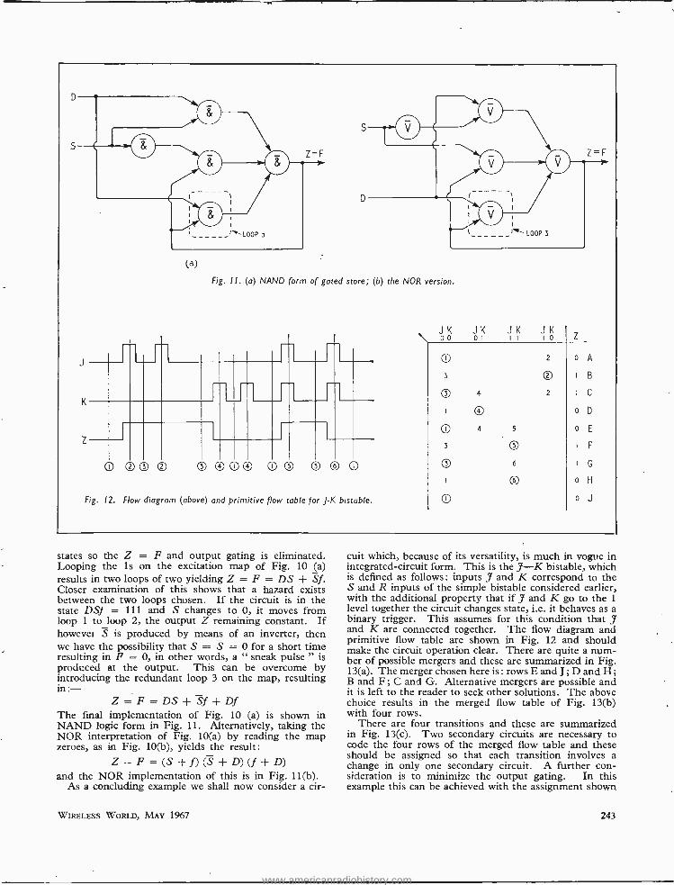
(a)
Fig. 1 1. (a) NAND form of gated store; (b) the NOR version.
\ JK 00
JK 01
JK JK I I I o Z
0 3
Q 4
2
Q 2
o A
I g
I C -i- K
® o D
0
O 3
Q
4 5
Q 6
o E
F
G
z
@®® 0® 0® 0 Q © © o H
Fig. 12. Flow diagram (above) and primitive flow table for f -K bistable. O o J
states so the Z = F and output gating is eliminated. Looping the is on the excitation map of Fig. 10 (a) results in two loops of two yielding Z = F = DS + Sf. Closer examination of this shows that a hazard exists between the two loops chosen. If the circuit is in the state DS} = 111 and S changes to 0, it moves from loop 1 to loop 2, the output Z remaining constant. If however S is produced by means of an inverter, then we have the possibility that S = S = 0 for a short time resulting in F = 0, in other words, a " sneak pulse " is produced at the output. This can be overcome by introducing the redundant loop 3 on the map, resulting in :-
Z = F = DS+Sf-}- Df The final implementation of Fig. 10 (a) is shown in NAND logic form in Fig. 11. Alternatively, taking the NOR interpretation of Fig. 10(a) by reading the map zeroes, as in Fig. 10(b), yields the result:
Z = F = (S + f) (S + D) (f + D) and the NOR implementation of this is in Fig. 11(b).
As a concluding example we shall now consider a cir-
WIRELESS WORLD, MAY 1967
cuit which, because of its versatility, is much in vogue in integrated -circuit form. This is the J -K bistable, which is defined as follows: inputs J and K correspond to the S and R inputs of the simple bistable considered earlier, with the additional property that if J and K go to the 1
level together the circuit changes state, i.e. it behaves as a binary trigger. This assumes for this condition that J and K are connected together. The flow diagram and primitive flow table are shown in Fig. 12 and should make the circuit operation clear. There are quite a num- ber of possible mergers and these are summarized in Fig. 13(a). The merger chosen here is : rows E and J; D and H; B and F; C and G. Alternative mergers are possible and it is left to the reader to seek other solutions. The above choice results in the merged flow table of Fig. 13(b) with four rows.
There are four transitions and these are summarized in Fig. 13(c). Two secondary circuits are necessary to code the four rows of the merged flow table and these should be assigned so that each transition involves a change in only one secondary circuit. A further con- sideration is to minimize the output gating. In this example this can be achieved with the assignment shown
243
www.americanradiohistory.com
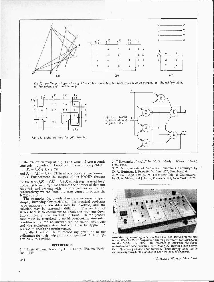
o
JK \ 00
3
3
óK
4
4
4
JK Jó Z
V
w
X
Y
w
V
X
Y
fI f\ o
V
X
Y
w
0
5
6
5
6
2
2
2
o
0
w
Y
V
(b) (c)
Fig. 13. (a) Merger diagram for Fig. 12, each line connecting two rows which could be merged. (b) Merged flow table. (c) Transitions and transition map.
flf2 0o
JK JK JK Ola
o I II JK
I 0
w
y
X Fig. 15. NAND
I o 00
00
0 0
00
00
II I 0I
I l
0 i
II I I
I I
11 ,
Io II V implementation of the J-K bistable.
F1 F2
Fig. 14. Excitation map for J-K bistable.
in the excitation map of Fig. 14 in which Z corresponds conveniently with F2. Looping the is as shown yields:-
Ft =.f2K -1- JK. and F5 = f2K - ft i + JK in which there are two common terms. Furthermore the output of the NAND element
for the term f K = f2K = 12+K which can be used for f, in the first term of F1. This reduces the number of elements required, and we end with the arrangement in Fig. 15. Alternatively we can loop the map zeroes to obtain the NOR circuit.
The examples dealt with above are necessarily quite simple, involving few variables. In practical problems large numbers of variables may be involved, and the solution may be extremely difficult. The method of attack here is to endeavour to break the problem down into simpler, inter -connected functions. In the process care must be exercised to avoid overlooking unwanted conditions. Often an answer can be found intuitively and the techniques described can then be applied in reverse to check the performance.
Finally I would like to record my gratitude to my colleagues for their help and encouragement in the prep- aration of this article.
REFERENCES 1. " Logic Without Tears," by H. R. Henly. Wireless World, Jan., 1965.
244
2. " Economical Logic," by H. R. Henly. Wireless World, Oct., 1965. 3. " The Synthesis of Sequential Switching Circuits," by D. A. Huffman, J. Franklin Institute, 257, Nos. 3 and 4. 4. " The Logic Design of Transistor Digital Computers," by G. A. Maley, and J. Earle, Prentice -Hall, New York, 1962.
Insertion of sound effects into television and sound programmes is simplified by this "programme effects generator" just introduced by the B.B.C. The effects are recorded in specially developed matchbox -size tape cassettes, each giving 30 seconds playing time. Four reproducing channels are provided. Tape playing speed can be
continuously varied, for example to alter the pace of footsteps.
WIRELESS WORLD, MAY 1967
1
www.americanradiohistory.com
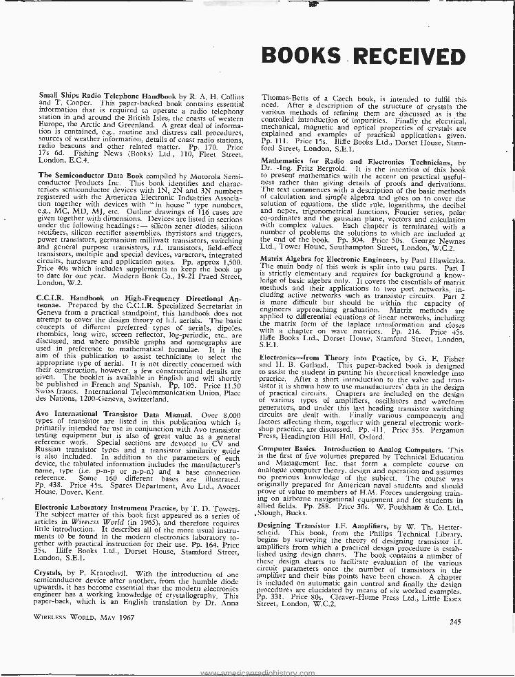
Small Ships Radio Telephone Handbook by R. A. H. Collins and T. Cooper. This paper- backed book contains essential information that is required to operate a radio telephony station in and around the British Isles, the coasts of western Europe, the Arctic and Greenland. A great deal of informa- tion is contained, e.g., routine and distress call procedures, sources of weather information, details of coast radio stations, radio beacons and other related matter. Pp. 170. Price 17s 6d. Fishing News (Books) Ltd., 110, Fleet Street, London, E.C.4.
The Semiconductor Data Book compiled by Motorola Semi- conductor Products Inc. This book identifies and charac- terizes semiconductor devices with 1N, 2N and 3N numbers registered with the American Electronic Industries Associa- tion together with devices with " in house " type numbers, e.g., MC, MD, MJ, etc. Outline drawings of 116 cases are given together with dimensions. Devices are listed in sections under the following headings:- silicon zener diodes, silicon rectifiers, silicon rectifier assemblies, thyristors and triggers, power transistors, germanium milliwatt transistors, switching and general purpose transistors, r.f, transistors, field -effect transistors, multiple and special devices, varactors, integrated circuits, hardware and application notes. Pp. approx 1,500. Price 40s which includes supplements to keep the book up to date for one year. Modern Book Co., 19 -21 Praed Street, London, W.2.
C.C.I.R. Handbook on High- Frequency Directional An- tennae. Prepared by the C.C.I.R. Specialized Secretariat in Geneva from a practical standpoint, this handbook does not attempt to cover the design theory of h.f. aerials. The basic concepts of different preferred types of aerials, dipoles, rhombics, long wire, screen reflector, log- periodic, etc., are discussed, and where possible graphs and nomographs are used in preference to mathematical formulae. It is the aim of this publication to assist technicians to select the appropriate type of aerial. It is not directly concerned with their construction, however, a few constructional details are given. The booklet is available in English and will shortly be published in French and Spanish. Pp. 105. Price 11.50 Swiss francs. International Telecommunication Union, Place des Nations, 1200- Geneva, Switzerland.
Ayo International Transistor Data Manual. Over 8,000 types of transistor are listed in this publication which is primarily intended for use in conjunction with Am transistor testing equipment but is also of great value as a general reference work. Special sections are devoted to CV and Russian transistor types and a transistor similarity guide is also included. In addition to the parameters of each device, the tabulated information includes the manufacturer's name, type (i.e. p -n -p or n -p -n) and a base connection reference. Some 160 different bases are illustrated. Pp. 438. Price 45s. Spares Department, Am Ltd., Avocet House, Dover, Kent.
Electronic Laboratory Instrument Practice, by T. D. Towers. The subject mauer of this book first appeared as a series of articles in Wiretc.ss World (in 1965), and therefore requires little introduction. It describes all of the more usual instru- ments to be found in the modern electronics laboratory to- gether with practical instruction for their use. Pp. 164. Price 35s. Iliffe Books Ltd., Dorset House, Stamford Street, London, S.E.1.
Crystals, by P. Kratochvil. With the introduction of one semiconductor device after another, from the humble diode upwards, it has become essential that the modem electronics engineer has a working knowledge of crystallography. This paper -back, which is an English translation by Dr. Anna
WIRELESS WORLD, MAY 1967
BOOKS RECEIVED
Thomas -Betts of a Czech book, is intended to fulfil this need. After a description of the structure of crystals the various methods of refining them are discussed as is the controlled introduction of impurities. Finally the electrical, mechanical, magnetic and optical properties of crystals are explained and examples of practical applications given. Pp. 111. Price 15s. Iliffe Books Ltd., Dorset House, Stam- ford Street, London, S.E.1.
Mathematics for Radio and Electronics Technicians, by Dr. -Ing. Fritz Bergtold. It is the intention of this book to present mathematics with the accent on practical useful- ness rather than giving details of proofs and derivations. The text commences with a description of the basic methods of calculation and simple algebra and goes on to cover the solution of equations, the slide rule, logarithms, the decibel and neper, trigonometrical functions, Fourier series, polar co- ordinates and the gaussian plane, vectors and calculation with complex values. Each chapter is terminated with a number of problems the solutions to which are included at the end of the book. Pp. 304. Price 50s. George Newnes Ltd., Tower House, Southampton Street, London, W.C.2. Matrix Algebra for Electronic Engineers, by Paul Hlawiczka. The main body of this work is split into two parts. Part I is strictly elementary and requires for background a know- ledge of basic algebra only. It covers the essentials of matrix methods and their applications to two port networks, in- cluding active networks such as transistor circuits. Part 2 is more difficult but should be within the capacity of engineers approaching graduation. Matrix methods are applied to differential equations of linear networks, including the matrix form of the laplace transformation and closes with a chapter on wave matrices. Pp. 216. Price 45s. Iliffe Books Ltd., Dorset House, Stamford Street, London, S.E.1.
Electronics -from Theory into Practice, by G. E. Fisher and H. B. Gatland. This paper- backed book is designed to assist the student in putting his theoretical knowledge into practice. After a short introduction to the valve and tran- sistor it is shown how to use manufacturers' data in the design of practical circuits. Chapters are included on the design of various types of amplifiers, oscillators and waveform generators, and under this last heading transistor switching circuits are dealt with. Finally various components and factors affecting them, together with general electronic work- shop practice, are discussed. Pp. 411. Price 35s. Pergamon Press, Headington Hill Hall, Oxford.
Computer Basics. Introduction to Analog Computers. This is the first of five volumes prepared by Technical Education and Management Inc. that form a complete course on analogue computer theory, design and operation and assumes no previous knowledge of the subject. The course was originally prepared for American naval students and should prove of value to members of H.M. Forces undergoing train- ing on airborne navigational equipment and for students in allied fields. Pp. 288. Price 30s. W. Foulsham & Co. Ltd., Slough, Bucks.
Designing Transistor I.F. Amplifiers, by W. Th. Hetter- scheid. This book, from the Philips Technical Library, begins by surveying the theory of designing transistor i.f. amplifiers from which a practical design procedure is estab- lished using design charts. The book contains a number of these design charts to facilitate evaluation of the various circuit parameters once the number of transistors in the amplifier and their bias points have been chosen. A chapter is included on automatic gain control and finally the design procedures are elucidated by means of six worked examples. Pp. 331. Price 80s. Cleaver -Hume Press Ltd., Little Essex Street, London, W.C.2.
245
www.americanradiohistory.com
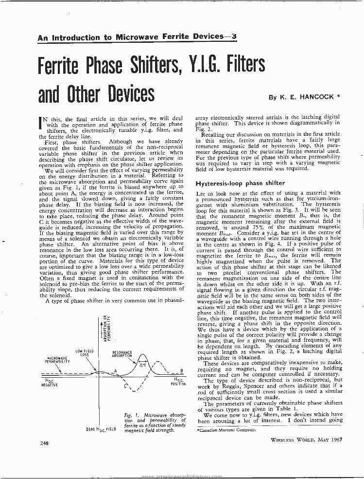
An Introduction to Microwave Ferrite Devices- 3
Ferrite Phase Shifters, V.I.G. Filters
and Other Devices
IN this, the final article in this series, we will deal with the operation and application of ferrite phase shifters, the electronically tunable y.i.g. filter, and
the ferrite delay line. First, phase shifters. Although we have already
covered the basic fundamentals of the non- reciprocal variable phase shifter in the previous article when describing the phase shift circulator, let us review its operation with emphasis on the phase shifter application.
We will consider first the effect of varying permeability on the energy distribution in a material. Referring to the microwave absorption and permeability curve again given as Fig. 1, if the ferrite is biased anywhere up to about point A, the energy is concentrated in the ferrite, and the signal slowed down, giving a fairly constant phase delay. If the biasing field is now increased, the energy concentration will decrease as interaction begins to take place, reducing the phase delay. Around point C it becomes negative as the effective width of the wave - guide is reduced, increasing the velocity of propagation. If the biasing magentic field is varied over this range by means of a solenoid we obtain an electronically variable phase shifter. An alternative point of bias is above resonance in the low loss area occurring there. It is, of course, important that the biasing range is in a low -loss portion of the curve. Materials for this type of device are optimized to give a low loss over a wide permeability variation, thus giving good phase shifter performance. Often a fixed magnet is used in conjunction with the solenoid to pre -bias the ferrite to the start of the perma- ability slope, thus reducing the current requirements of the solenoid.
A type of phase shifter in very common use in phased-
MICROWAVE PERMEABILITY
LOW FIELD LOSS
NEGATIVE
246
RESONANCE ABSORPTION
AH i \
A
C\V
ZERO Roc.FIELO
H D.C. POSITIVE
Fig. 1. Microwave absorp- tion and permeability of ferrite as a function of steady magnetic field strength.
By K. E. HANCOCK *
array electronically steered aerials is the latching digital phase shifter. This device is shown diagrammatically in Fig. 2.
Recalling our discussion on materials in the first article in this series, ferrite materials have a fairly large remanent magnetic field or hysteresis loop, this para- meter depending on the particular ferrite material used. For the previous type of phase shift where permeability was required to vary in step with a varying magnetic field of low hysteresis material was required.
Hysteresis -loop phase shifter
Let us look now at the effect of using a material with a pronounced hysteresis such as that for yttrium -iron- garnet with aluminium substitution. The hysteresis loop for this material is shown as Fig. 3. It will be seen that the remanent magnetic moment Br, that is, the magnetic moment remaining after the external field is removed, is around 75% of the maximum magnetic moment Borax- Consider a y.i.g. bar set in the centre of a waveguide with a control wire running through a hole in the centre as shown in Fig. 4. If a positive pulse of current is passed through the control wire sufficient to magnetize the ferrite to B,n x, the ferrite will remain highly magnetized when the pulse is removed. The action of this phase shifter at this stage can be likened to two parellel conventional phase shifters. The remanent magnetization on one side of the centre line is down whilst on the other side it is up. With an r.f. signal flowing in a given direction the circular r.f. mag- netic field will be in the same sense on both sides of the waveguide as the biasing magnetic field. The two inter- actions will aid each other and we will get a large positive phase shift. If another pulse is applied to the control line, this time negative, the remanent magnetic field will reverse, giving a phase shift in the opposite direction. We thus have a device which by the application of a single pulse of the correct polarity will provide a change in phase, that, for a given material and frequency, will be dependent on length. By cascading elements of any required length as shown in Fig. 2, a latching digital phase shifter is obtained.
These devices are comparatively inexpensive to make, requiring no magnet, and they require no holding current and can be computer controlled if necessary.
The type of device described is non -reciprocal, but work by Reggia, Spencer and others indicate that if a rod of sufficiently small cross section is used a similar reciprocal device can be made.
The parameters of currently obtainable phase shifters of various types are given in Table 1.
We come now to y.i.g. filters, new devices which have been arousing a lot of interest. I don't intend going
*Canadian Marconi Company.
WIRELESS WORLD, MAY 1967
www.americanradiohistory.com
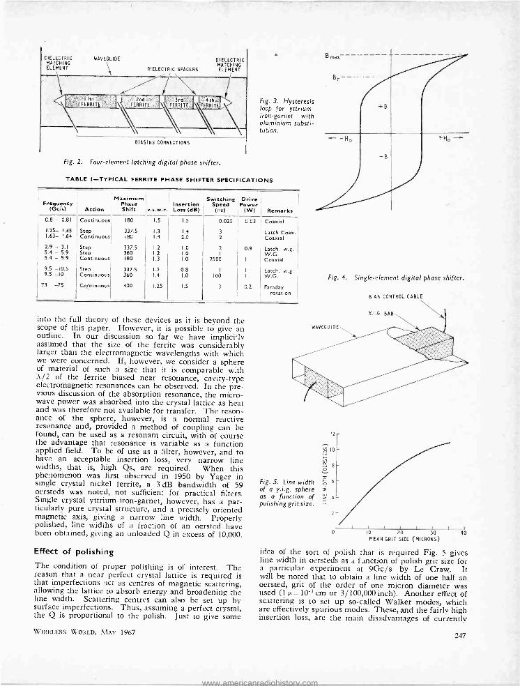
DIELECTRIC MATCHING ELEMENT
WAVEGUIDE
DIELECTRIC SPACERS
- / I
DIELECTRIC MATCHING ELEMENT
Ist ERRITE
2nd FERRITE
'- 3rd k .4thóa FERRITE XERRITE \
BIASING CONNECTIONS
Fig. 2. Four- element latching digital phase shifter.
Fig. 3. Hysteresis loop for yttrium - iron -garnet with aluminium substi- tution.
TABLE I- TYFICAL FERRITE PHASE SHIFTER SPECIFICATIONS
Maximum Frequency Phase Insertion
(Gc /s) Action Shift Loss (dB)
Switching Drive Speed Power (i,$) (W) Remarks
0.8 - 0.81 Continuous 180 1.5 1.5 0.020 0.03 Coaxial
t.25- 1.45 Step 337.5 1.3 1.4 3 Latch Coax. 1.63- 1.64 Continuous 180 1.4 2.0 2 Coaxial
2.9 - 3.1 Step 337.5 1.2 1.0 2 0.9 Latch. w.g. 5.4 - 5.9 Step 360 1.2 1.0 I W.G. 5.4 - 5.9 Continuous 180 1.3 1.0 2500 I Coaxial
9.5 -10.5 Step 337.5 1.2 0.8 1 I Latch. w.g. 9.5 -10 Continuous 360 1.4 1.0 100 I W.G. Fig. 4.
73 -75 400 1.25 1.5 3 0.2 Faraday rotation
into the full theory of these devices as it is beyond the scope of this paper. However, it is possible to give an outline. In our discussion so far we have implicitly assumed that the size of the ferrite was considerably larger than the electromagnetic wavelengths with which we were concerned. If, however, we consider a sphere of material of such a size that it is comparable with A/2 of the ferrite biased near resonance, cavity -type electromagnetic resonances can be observed. In the pre- vious discussion of the absorption resonance, the micro- wave power was absorbed into the crystal lattice as heat and was therefore not available for transfer. The reson- ance of the sphere, however, is a normal reactive resonance and, provided a method of coupling can be found, can be used as a resonant circuit, with of course the advantage that resonance is variable as a function applied field. To be of use as a filter, however, and to have an acceptable insertion loss, very narrow line widths, that is, high Qs, are required. When this phenomenon was first observed in 1950 by Yager in single crystal nickel ferrite, a 3 dB bandwidth of 59 oersteds was noted, not sufficient for practical filters. Single crystal yttrium -iron -garnet, however, has a par- ticularly pure crystal structure, and a precisely oriented magnetic axis, giving a narrow line width. Properly polished, line widths of a fraction of an oersted have been obtained, giving an unloaded Q in excess of 10,000.
Effect of polishing
The condition of proper polishing is of interest. The reason that a near perfect crystal lattice is required is that imperfections act as centres of magnetic scattering, allowing the lattice to absorb energy and broadening the line width. Scattering centres can also be set up by surface imperfections. Thus, assuming a perfect crystal, the Q is proportional to the polish. Just to give some
WIRELESS WORLD, MAY 1967
WAVEGUIDE
Single -element digital phase shifter.
BIAS CONTROL CABLE
Y.I.G. BAR
Fig. S. Line width of a y.i.g. sphere as a function of polishing grit size.
12
2
10 20 30 40 MEAN GRIT SIZE (MICRONS)
idea of the sort of polish that is required Fig. 5 gives line width in oersteds as a function of polish grit size for a particular experiment at 9Gc /s by Le Craw. It will be noted that to obtain a line width of one half an oersted, grit of the order of one micron diameter was used (1 t =10-' cm or 3/100,000 inch). Another effect of scattering is to set up so- called Walker modes, which are effectively spurious modes. These, and the fairly high insertion loss, are the main disadvantages of currently
247
www.americanradiohistory.com
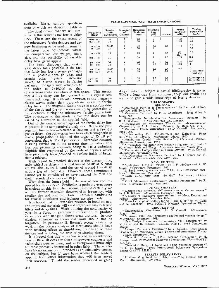
available filters, sample specifica- tions of which are shown in Table 2.
The final device that we will con- sider in this series is the ferrite delay line. These are the most recent of the microwave ferrite devices and are now beginning to be used in some of the latest radar equipments, where the comparative low weight, small size, and the possibility of variable delay have great appeal.
The basic discovery that makes y.i.g. delay lines possible is the fact that fairly low loss acoustic propaga- tion is possible through y.i.g. and certain other crystals. Acoustic waves, or elastic waves in ferrite parlance, propagate with velocities of
TABLE 2- TYPICAL Y.I.G. FILTER SPECIFICATIONS
Frequency (Gcls)
Nominal 3 dB
Bandwidth
Number of
Cavities
Rejection Maximum
(dB)
Insertion Loss (dB)
Inband Spurious
v.s.w.r. (dB)
Tuning Sensitivity
(mA)
0.09- 0.3 8 2 20 8 -20 2.5
0.3 - 1.0 22 2 20 4 -20 2.5
1.0 -22.0 10-35 1 30 1.5 2.1 -10 3.0
1.0 -2.0 25 4 70 4 4.6
2.0 - 4.0 15 4 80 6 2.1 (2) -25, -10
3.5
2.0 - 4.0 25 I 30 1 1.5 -25 10.0
4.0 - 8.0 30 4 60 3 1.5 -20 10.0
4.0 - 8.0 30 I 20 1.5 1.2 -20 5
8.0 -12.4 10-50 2 50 2.5 2.1 - I 3
8.0 -12.4 20-50 2 50 3 2.1 3 non recip- rocal w.g.
12.4 -18 20 2 30 2.5 1.5 12 waveguide
26 -40 20 2 30 5 1.5 16 waveguide
the order of 1 /10,000 of that of electromagnetic radiation in free space. This means that a 1 µs delay can be obtained with a crystal less than # inch long. It is normal, however, to use magneto- elastic waves rather than pure elastic waves in ferrite delay lines. The magneto -elastic wave is a combination of the elastic and the spin waves set up by precession of the electrons during the microwave ferrite interaction. The advantage of this mode is that the delay can be varied by alteration of the applied field.
One of the main disadvantages of the ferrite delay line at present is its comparatively high loss. While the pro- pagation loss is low- between a fraction and a few dB per ps delay -the conversion loss from electromagnetic to elastic propagation is high, of the order of 25 dB per conversion, that is 50 dB per device. Extensive research is being carried on at the present time to reduce this loss, one promising approach being to use a cadmium sulphide film evaporated on the ends of crystals which have previously been polished to surface finish of better than a micron.
With regard to practical devices at the present time, units with 3 µs delay and a total loss of 70 dB at X band are available, as are L band devices of around 1 cs delay with a loss of 10 -15 dB. However, these components cannot yet be considered to have reached the " off the shelf " standard component stage.
What does the future hold in the way of new and im- proved ferrite devices? Prediction is probably even more hazardous in this field than normal; almost certainly we will see further extension downward in frequency, with smaller size and cost reduction. Increased bandwidths for coaxial circulators and isolators are also likely.
It is hoped that the extensive research in hand on new and improved materials will yield improvements in ferrite filters and delay lines. Work utilizing the nonlinearity of y.i.g. in a form of parametric interaction to produce delay lines with net gain shows great promise. In con- clusion, advances in theoretical work should not be forgotten. In particular H. Bosma's recent outstanding work in the precise analysis of circulators should have wide reaching effects in simplifying the design of these devices and reducing the cost of producing them.
It is hoped that this series has served as an introduc- tion to these devices for those microwave engineers and technicians new to them, and as background knowledge for those primarily interested in other fields. The articles have by no means been intended as an exhaustive treatise on the subject, but if they have whetted the reader's appetite for further information they will have served their purpose. To aid the reader interested in going
248
deeper into the subject a partial bibliography is given. While a long way from complete, they will enable the reader to gain a wide knowledge of ferrite devices.
BIBLIOGRAPHY GENERAL
" Microwave Ferrites & Ferrimagnetics " by Lax and Button. McGraw Hill Book Co., N.Y.
" Microwave Ferrites " by P. B. Charricoats. John Wiley &
Sons, N.Y. Ferrites-An Introduction for Microwave Engineers " by
R. A. Waldron. D. Van Nostrand Co., London. " Introduction to Microwave Theory and Measurements,"
Chapter 10, by A. L. Lance. McGraw Hill Book Co., N.Y. " Microwave Ferrite Interaction " by D. Caswell. Microwaves,
June 1963. " Understanding Field Displacement and Differential Phase
Shift " by D. Caswell. Microwaves, March 1965. " Miniaturized Coaxial Ferrite Devices " by Clark and Harrison.
Microwave Journal, June 1962. " A magnetless millimeter wave isolator using strontium ferrite "
by Vilmur, Ishir and Wang. Microwave Journal, March 1962. " Temperature Compensation of Ferrite Devices " by D. Caswell.
Microwaves, November 1963. " A Discussion on Microwave Ferrites " by J. Brauer and N.
Korolkoff. Electronic Industries, May 1962.
Y.I.G. FILTERS " Application of Y.I.G. Devices " by J. F. McCabe and A. W.
Shaw. Microwaves, September 1965. " L Band sweep generator uses Y.I.G. tuned transistor oscil-
lator." Microwaves, May 1965. " Single Y.I.G. filter tuner 1 -10 Gc." Microwaves, October
1965. Y.I.G. Microwave Electronically Tunable Preselectors " by R.
Blau. Microwave Journal, May 1962.
PHASE SHIFTERS " Electronically controlled shifters -a state of the art survey "
by J. B. Brinton. Microwaves, December 1964. " A review of microwave phase shifters " by Molz, Dodson and
Pribble. Microwaves, December 1964. " Ferroelectric phase shifters for VHF and UHF " by M. Cohn
and A. Ekenbery. 1962 PGMTT National Symposium Digest.
CIRCULATORS " Understanding Circulators " by D. Caswell. Microwaves,
August 1963. Miniature VHF -UHF circulators use lumped element design."
Microwaves, December 1963. " New Design Techniques for miniature VHF Circulators " by
V. Dunn and R. Roberts. I.E.E.E. PGHTT 1965 Symposium Digest.
Lumped Element Y Circulator " by Y. Koviske. International Conference on Microwave Circuit Theory and Information Thcory -Tokyo, September 1964.
" Theoretical Aspects of 3 -Port Junction Circulators " by H. Bosma. 1966 International Microwave Symposium Digest G -MTT L.E.E.E.
Theoretical Design of 3 -port and 4 -port waveguide circulator " by L. E. Davies. 1966 International Microwave Symposium Digest G -MTT I.E.E.E.
FERRITE DELAY LINES " Understanding Solid State Delay Lines " by Hernian van de
Vaart. Microwaves, July 1966.
WIRELESS WORLD, MAY 1967
www.americanradiohistory.com
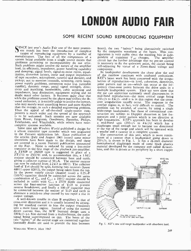
LONDON AUDIO FAIR SOME RECENT SOUND REPRODUCING EQUIPMENT
SINCE last year's Audio Fair one of -the most promin- ent trends has been the introduction of complete ranges of reproducing equipment by a number of
manufacturers. The fact of all the components of a system being available from a single source means that problems pertaining to incompatability do not arise. Such problems might involve the nature of the amplifier load, its efficiency, impedance, power handling capability and damping; signal levels, signal -to -noise ratios, equal- ization, distortion factors, input and output impedances of tape recorders, microphone, tuner(s) and decoder, and pickup; not to mention crosstalk, screening, earth loops, power supply problems, extraneous noise (e.g. turntable rumble), dynamic range, aerial signal strength, direc- tivity and matching, bandwidths, cable screening and impedances, heat dissipation, equipment styling and no doubt many other factors. It becomes quite clear that while the problems posed by the above may titillate the de- voted enthusiast, it is entirely unfair to involve the layman, who may merely want something better and more flexible than the average, in such a detailed engineering problem. Thus the appeal of off -the -shelf single- source com- ponents is much wider and the spread of the approach is to be welcomed. Such systems are now available from Braun, Ferguson, Goodmans, Parmeko, Philips, Telefunken, and Wharfedale, while others have near - complete systems available.
Some time ago Wireless World published a design for a silicon transistor tape recorder which was originated in the Ferranti applications lab. Since publication of the articles (July and August 1965 issues) some minor alterations have been made to the design, and these are covered in a recent Ferranti publication announced at the Fair. Noise is reduced by using a less -noisy transistor in the first stage of the playback pre -amplifier. A ZT929 or 2N929 type is suggested in place of a ZT1711 or 2N1711 and, to accommodate this, a 1 M<2 resistor should be connected between base and earth, giving a collector current of 50 ILA. The emitter resistor can now be reduced from 2.2 kS2 to 680 fl. The collector load of Tr4 should be split, forming two resistors (lower 680 S2 upper 820 S2), the output being taken from the tap. In the power supply circuit (August issue) a 0.25 /4F (100 V) capacitor should be connected across the series combination of C , and C,;,; a 100!.2 resistor should be included in series with C,; ; a ZS70 diode connected across the base -emitter junction of Tr25 to prevent reverse breakdown; and finally a 500 /4F capacitor may be connected between the emitter of Tr25 and earth to eliminate a switch -on plop caused by too rapid a rise in output voltage.
A well -known trouble in class B amplifiers is that of cross -over distortion and it is usually lessened by arrang- ing for standing current to bias the output transistors into a more linear region. Instead of using the normal direct current bias, the 30 W Ferranti design uses a 100 kc /s a.c. bias derived from a multivibrator, the audio signal being superimposed on this. The bases of the two halves of the output stage are connected together (normally diodes are used to provide the bias between
WIRELESS WORLD, MAY 1967
bases), the two " halves " being alternatively switched by the composite waveform at the bases. This con- figuration is very stable since the standing bias is inde- pendent of transistor V es changes. The amplifier circuit has the further advantage that no pre -set control is necessary to fix the quiescent point, the circuit being self- adjusting by virtue of a Zener -fixed voltage and comparator.
In loudspeaker development the chase after the end of the rainbow continues with unabated enthusiasm. KEF's latest work has been concerned with the irregu- larities of reproduction -in level, coloration, directivity, polar pattern and so on -which can occur at the fre- quency cross -over points between the drive units in a multiple loudspeaker system. They say tests show that the ear can appreciate extremely small discrepancies in mid -band reproduction -the most critical range being 250 c/s to 4 kc /s -and it is in this region that the cross- over irregularities usually occur. The response in the overlap region is, in fact, very difficult to control. The problem can be avoided, of course, by using a single wide -range loudspeaker, but those of conventional con- struction are subject to Doppler distortion at low fre- quencies and a polar pattern which is too directive at high frequencies. KEF's approach has been to develop a mid -band unit (250c /s to 4kc /s) which has a diaphragm small enough not to become too directional at the top of the range and which will be operated with a woofer and a tweeter in a complete system.
The construction of this unit, which is more remin- iscent of a tweeter than a loudspeaker going down to 250c /s, is shown in Fig. 1. It has a 21-inch diameter hemispherical diaphragm made of some black plastics material developed by the company and called Acousti- lene, and this is driven at its periphery by a short copper
MAGNET VOICE COIL ON
ALUMINIUM FORMER
:"///;/////////// \.
MO1t
SULPHUR FILLING
- 33in LONG FLEXIBLE PIPE FILLED WITH LONG-HAIR WOOL
DOME DIAPHRAGM
SURROUND
Fig. I. KEF's new mid -range loudspeaker with absorbent load.
249
www.americanradiohistory.com
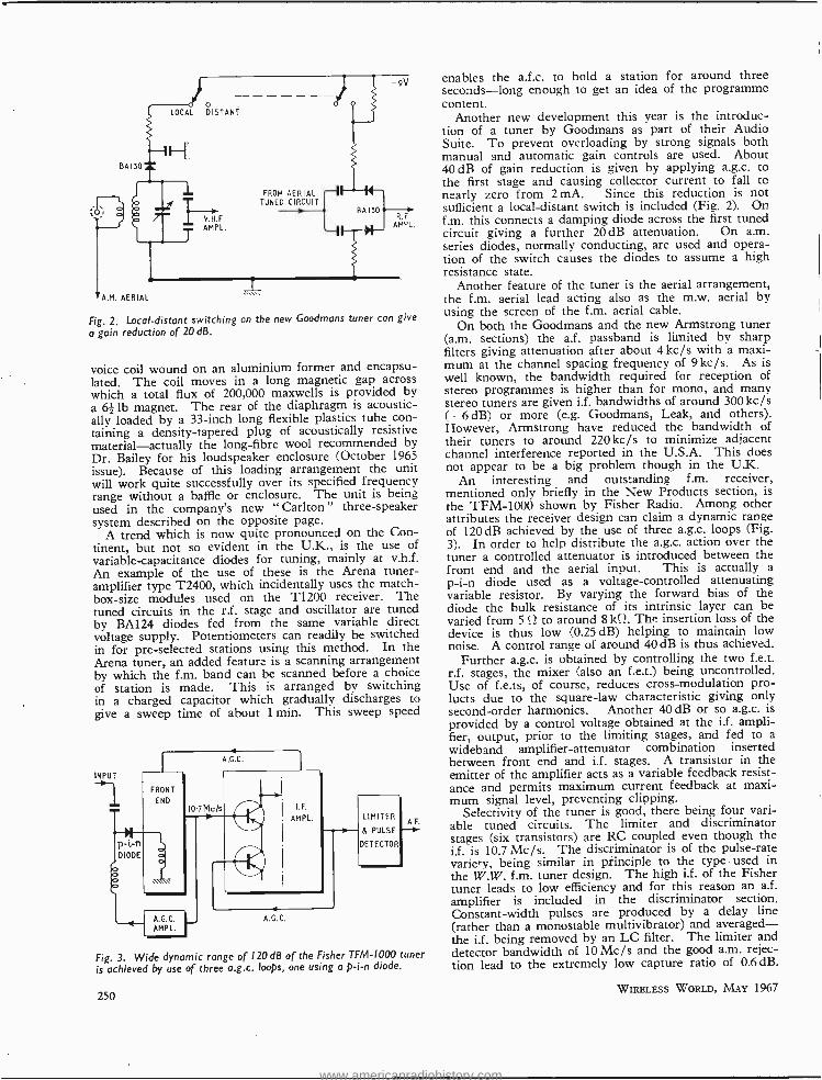
Fig. 2. Local- distant switching on the new Goodmans tuner can give
o gain reduction of 20 dB.
voice coil wound on an aluminium former and encapsu- lated. The coil moves in a long magnetic gap across which a total flux of 200,000 maxwells is provided by a 62 lb magnet. The rear of the diaphragm is acoustic- ally loaded by a 33 -inch long flexible plastics tube con- taining a density -tapered plug of acoustically resistive material- actually the long -fibre wool recommended by Dr. Bailey for his loudspeaker enclosure (October 1965 issue). Because of this loading arrangement the unit will work quite successfully over its specified frequency range without a baffle or enclosure. The unit is being used in the company's new "Carlton" three- speaker system described on the opposite page.
A trend which is now quite pronounced on the Con- tinent, but not so evident in the U.K., is the use of variable- capacitance diodes for tuning, mainly at v.h.f. An example of the use of these is the Arena tuner- amplifier type T2400, which incidentally uses the match- box -size modules used on the T1200 receiver. The tuned circuits in the r.f. stage and oscillator are tuned by BA124 diodes fed from the same variable direct voltage supply. Potentiometers can readily be switched in for pre -selected stations using this method. In the Arena tuner, an added feature is a scanning arrangement by which the f.m. band can be scanned before a choice of station is made. This is arranged by switching in a charged capacitor which gradually discharges to give a sweep time of about 1 min. This sweep speed
Fig. 3. Wide dynamic range of 120 dB of the Fisher TFM -1000 tuner is achieved by use of three a.g.c. loops, one using a p -i -n diode.
250
enables the a.f.c. to hold a station for around three seconds -long enough to get an idea of the programme content.
Another new development this year is the introduc- tion of a tuner by Goodmans as part of their Audio Suite. To prevent overloading by strong signals both manual and automatic gain controls are used. About 40 dB of gain reduction is given by applying a.g.c. to the first stage and causing collector current to fall to nearly zero from 2mA. Since this reduction is not sufficient a local- distant switch is included (Fig. 2). On f.m. this connects a damping diode across the first tuned circuit giving a further 20 dB attenuation. On a.m. series diodes, normally conducting, are used and opera- tion of the switch causes the diodes to assume a high resistance state.
Another feature of the tuner is the aerial arrangement, the f.m. aerial lead acting also as the m.w. aerial by using the screen of the f.m. aerial cable.
On both the Goodmans and the new Armstrong tuner (a.m. sections) the a.f. passband is limited by sharp filters giving attenuation after about 4 kc /s with a maxi- mum at the channel spacing frequency of 9 kc /s. As is well known, the bandwidth required for reception of stereo programmes is higher than for mono, and many stereo tuners are given i.f. bandwidths of around 300 kc /s (- 6 dB) or more (e.g. Goodmans, Leak, and others). However, Armstrong have reduced the bandwidth of their tuners to around 220 kc /s to minimize adjacent channel interference reported in the U.S.A. This does not appear to be a big problem though in the U.K.
An interesting and outstanding f.m. receiver, mentioned only briefly in the New Products section, is the TFM -1000 shown by Fisher Radio. Among other attributes the receiver design can claim a dynamic range of 120 dB achieved by the use of three a.g.c. loops (Fig. 3). In order to help distribute the a.g.c. action over the tuner a controlled attenuator is introduced between the front end and the aerial input. This is actually a p -i -n diode used as a voltage- controlled attenuating variable resistor. By varying the forward bias of the diode the bulk resistance of its intrinsic layer can be varied from 5 .2 to around 8 kQ. The insertion loss of the device is thus low (0.25 dB) helping to maintain low noise. A control range of around 40 dB is thus achieved.
Further a.g.c. is obtained by controlling the two f.e.t. r.f. stages, the mixer (also an f.e.t.) being uncontrolled. Use of f.e.ts, of course, reduces cross -modulation pro - lucts due to the square -law characteristic giving only second -order harmonics. Another 40 dB or so a.g.c. is provided by a control voltage obtained at the i.f. ampli- fier, output, prior to the limiting stages, and fed to a wideband amplifier -attenuator combination inserted between front end and i.f. stages. A transistor in the emitter of the amplifier acts as a variable feedback resist- ance and permits maximum current feedback at maxi- mum signal level, preventing clipping.
Selectivity of the tuner is good, there being four vari- able tuned circuits. The limiter and discriminator stages (six transistors) are RC coupled even though the i.f. is 10.7 Mc /s. The discriminator is of the pulse -rate variety, being similar in principle to the type used in the W.W. f.m. tuner design. The high i.f. of the Fisher tuner leads to low efficiency and for this reason an a.f. amplifier is included in the discriminator section. Constant -width pulses are produced by a delay line (rather than a monostable multivibrator) and averaged - the ii. being removed by an LC filter. The limiter and detector bandwidth of 10 Mc /s and the good a.m. rejec- tion lead to the extremely low capture ratio of 0.6 dB.
WIRELESS WORLD, MAY 1967
www.americanradiohistory.com
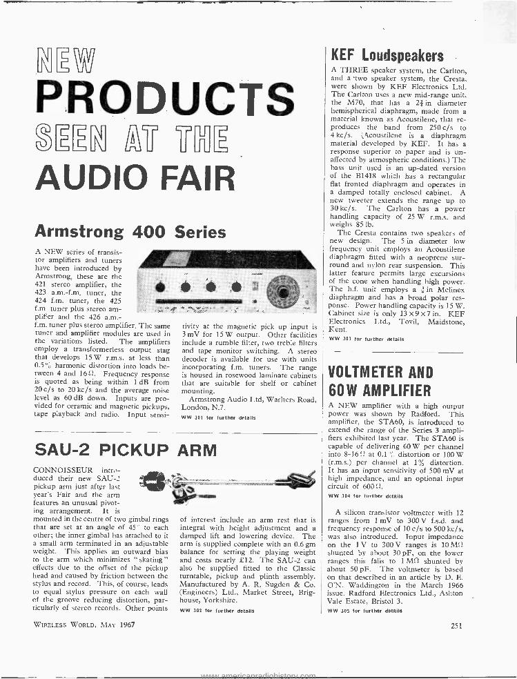
PRODUCTS 2r1 "YL
AUDIO FAIR
Armstrong 400 Series A NEW series of transis- tor amplifiers and tuners have been introduced by Armstrong, these are the 421 stereo amplifier, the 423 a.m. -f.m. tuner, the 424 f.m. tuner, the 425 f.m ,. tuner plus stereo am- plifier and the 426 a.m. - f.m. tuner plus stereo amplifier. The same tuner and amplifier modules are used in the variations listed. The amplifiers employ a transformerless output stag thai develops 15 W r.m.s. at less than 0.5"' harmonic distortion into loads be- tween 4 and 1611. Frequency response is quoted as being within 1 dB from 20 c/s to 20 kc /s and the average noise level as 60 dB down. Inputs are pro- vided for ceramic and magnetic pickups, tape playback and radio. Input sensi-
tivity at the magnetic pick up input is 3 mV for 15 W output. Other facilities include a rumble filter, two treble filters and tape monitor switching. A stereo decoder is available for use with units incorporating f.m. tuners. The range is housed in rosewood laminate cabinets that are suitable for shelf or cabinet mounting.
Armstrong Audio Ltd, Warlters Road, London, N.7. WW 301 for further details
SAU -2 PICKUP ARM CONNOISSEUR intro- duced their new SAU-2 pickup arm just after last year's Fair and the arm features an unusual pivot- ing arrangement. It is mounted in the centre of two gimbal rings that are set at an angle of 45' to each other; the inner gimbal has attached to it a small arm terminated in an adjustable weight. This applies an outward bias to the arm which minimizes " skating " effects due to the offset of the pickup head and caused by friction between the stylus and record. This, of course, leads to equal stylus pressure on each wall of the groove reducing distortion, par- ticularly of stereo records. Other points
WIRELESS WORLD, MAY 1967
of interest include an arm rest that is integral with height adjustment and a damped lift and lowering device. The arm is supplied complete with an 0.6 gm balance for setting the playing weight and costs nearly £12. The SAU -2 can also be supplied fitted to the Classic turntable, pickup and plinth assembly. Manufactured by A. R. Sugden & Co. (Engineers) Ltd., Market Street, Brig- house, Yorkshire. WW 302 for further details
KEF Loudspeakers A THREE speaker system, the Carlton, and a two speaker system, the Cresta, were shown by KEF Electronics Ltd. The Carlton uses a new mid -range unit, the M70, that has a 2, in diameter hemispherical diaphragm, made from a material known as Acoustilene, that re- produces the band from 250c /s to 4 kc /s. Okcoustilene is a diaphragm material developed by KEF. It has a response superior to paper and is un- affected by atmospheric conditions.) The bass unit used is an up -dated version of the B1418 which has a rectangular fiat fronted diaphragm and operates in a damped totally enclosed cabinet. A new tweeter extends the range up to 30 kc /s. The Carlton has a power handling capacity of 25 W r.m.s. and weighs 85 lb.
The Cresta contains two speakers of new design. The 5 in diameter low frequency unit employs an Acoustilene diaphragm fitted with a neoprene sur- round and nylon rear suspension. This latter feature permits large excursions of the cone when handling high power. The h.f. unit employs a ¡An Melinex diaphragm and has a broad polar res- ponse. Power handling capacity is 15 W. Cabinet size is only 13 X 9 X 7 in. KEF Electronics Ltd., Tovil, Maidstone, Kent. WW 303 for further details
VOLTMETER AND
60W AMPLIFIER A NEW amplifier with a high output power was shown by Radford. This amplifier, the STA60, is introduced to extend the range of the Series 3 ampli- fiers exhibited last year. The STA60 is capable of delivering 60 W per channel into 8 -1612 at 0.1 distortion or 100 W (r.m.s.) per channel at 1% distortion. It has an input sensitivity of 500 mV at high impedance, and an optional input circuit of 60011. WW 304 for further details
A silicon transistor voltmeter with 12 ranges from 1 mV to 300 V f.s.d. and frequency response of 10 c/s to 500 kc /s, was also introduced. Input impedance on the 1 V to 300 V ranges is 10 M11 shunted by about 30 pF, on the lower ranges this falls to 1 Mû shunted by about 50 pF. The voltmeter is based on that described in an article by D. E. O'N. Waddington in the March 1966 issue. Radford Electronics Ltd., Ashton Vale Estate, Bristol 3. WW 305 For further details
251
www.americanradiohistory.com
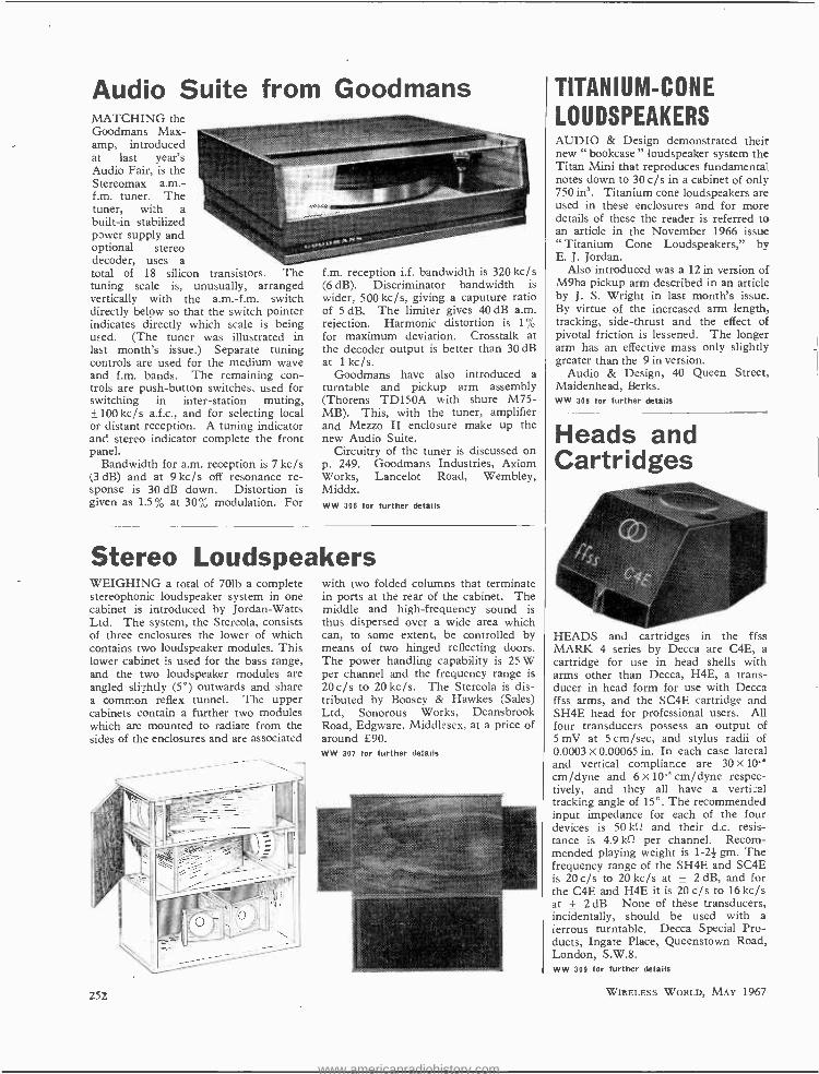
Audio Suite from Goodmans MATCHING the Goodmans Max - amp, introduced at last year's Audio Fair, is the Stereomax a.m. - f.m. tuner. The tuner, with a built -in stabilized power supply and optional stereo decoder, uses a total of 18 silicon transistors. The tuning scale is, unusually, arranged vertically with the a.m. -f.m. switch directly below so that the switch pointer indicates directly which scale is being used. (The tuner was illustrated in last month's issue.) Separate tuning controls are used for the medium wave and f.m. bands. The remaining con- trols are push- button switches, used for switching in inter- station muting, ±100 kc/ s a.f.c., and for selecting local or distant reception. A tuning indicator and stereo indicator complete the front panel.
Bandwidth for a.m. reception is 7 kc /s (3 dB) and at 9 kc /s off resonance re- sponse is 30 dB down. Distortion is given as 1.5% at 30% modulation. For
f.m. reception i.f. bandwidth is 320 kc /s (6 dB). Discriminator bandwidth is wider, 500 kc /s, giving a caputure ratio of 5 dB. The limiter gives 40 dB a.m. rejection. Harmonic distortion is 1% for maximum deviation. Crosstalk at the decoder output is better than 30 dB at 1 kc /s.
Goodmans have also introduced a turntable and pickup arm assembly (Thorens TD150A with shure M75- MB). This, with the tuner, amplifier and Mezzo II enclosure make up the new Audio Suite.
Circuitry of the tuner is discussed on p. 249. Goodmans Industries, Axiom Works, Lancelot Road, Wembley, Middx. WW 306 for further details
Stereo Loudspeakers WEIGHING a total of 701b a complete stereophonic loudspeaker system in one cabinet is introduced by Jordan -Watts Ltd. The system, the Stereola, consists of three enclosures the lower of which contains two loudspeaker modules. This lower cabinet is used for the bass range, and the two loudspeaker modules are angled slightly (5 °) outwards and share a common reflex tunnel. The upper cabinets contain a further two modules which are mounted to radiate from the sides of the enclosures and are associated
with two folded columns that terminate in ports at the rear of the cabinet. The middle and high -frequency sound is thus dispersed over a wide area which can, to some extent, be controlled by means of two hinged reflecting doors. The power handling capability is 25 W per channel and the frequency range is 20c /s to 20kc /s. The Stereola is dis- tributed by Boosey & Hawkes (Sales) Ltd, Sonorous Works, Deansbrook Road, Edgware, Middlesex, at a price of around £90. WW 307 for further details
252
TITANIUM -CONE
LOUDSPEAKERS AUDIO & Design demonstrated their new " bookcase " loudspeaker system the Titan Mini that reproduces fundamental notes down to 30 c/s in a cabinet of only 750 in'. Titanium cone loudspeakers are used in these enclosures and for more details of these the reader is referred to an article in the November 1966 issue " Titanium Cone Loudspeakers," by E. J. Jordan.
Also introduced was a 12 in version of M9ba pickup arm described in an article by J. S. Wright in last month's issue. By virtue of the increased arm length, tracking, side -thrust and the effect of pivotal friction is lessened. The longer arm has an effective mass only slightly greater than the 9 in version.
Audio & Design, 40 Queen Street, Maidenhead, Berks. WW 308 for further details
Heads and Cartridges
HEADS and cartridges in the ffss MARK 4 series by Decca are C4E, a cartridge for use in head shells with arms other than Decca, H4E, a trans- ducer in head form for use with Decca ffss arms, and the SC4E cartridge and SH4E head for professional users. All four transducers possess an output of 5 mV at 5 cm /sec, and stylus radii of 0.0003 x 0.00065 in. In each case lateral and vertical compliance are 30 x 10- cm /dyne and 6 x 10-° cm /dyne respec- tively, and they all have a vertical tracking angle of 15°. The recommended input impedance for each of the four devices is 50 kll and their d.c. resis- tance is 4.9 kffl per channel. Recom- mended playing weight is 1 -21 gm. The frequency range of the SH4E and SC4E is 20 c/s to 20 kc /s at ± 2 dB, and for the C4E and H4E it is 20 c/s to 16 kc /s at ± 2 dB. None of these transducers, incidentally, should be used with a ferrous turntable. Decca Special Pro- ducts, Ingate Place, Queenstown Road, London, S.W.8. WW 309 for further details
WIRELESS WORLD, MAY 1967
www.americanradiohistory.com
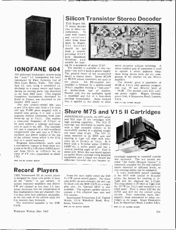
IONOFANE 604 AN additional loudspeaker system using the " ionic " h.f. loudspeaker has been introduced by Fane Acoustics Ltd of Hick Lane, Batley, Yorks. The Iono- fane h.f. unit, using a modulated r.f. discharge as a sound source and hence having no moving parts, was described in the June 1965 issue. (The original Ionophone loudspeaker, developed by Klein in France, was described in the January 1952 issue.)
The new system -model 604 -uses a new 12 in drive unit (with a 2 in voice coil and 17,000 gauss magnet) with a treated cone giving, it is said, a level response without colorations from cone break -up up to 5 kc /s. This enables a cross -over frequency of 3.5 kc /s to be used without a separate mid -range unit as used in the 603. The Ionofane h.f. unit is mounted in a well -ventilated compartment (the unit uses a 27 Mc /s oscillator and power supply) at the top of the cabinet, below which is the 12 in unit in a sealed enclosure.
Response measurements, made with a microphone 1 metre in front show res- ponse to be 80 ± 2 dB above 0.0002 dyne/ cm' from 50 c/s to >22 kc /s for an input of 4 V r.m.s (equivalent to about 1 W).
WW 310 for further details
Silicon Transistor Stereo Decoder THE Rogers Mk. II stereo decoder can, in many cir- cumstances, be used with tuners and receivers apart from those made by Rogers. The decoder should be fed from a receiver providing 0.5 -1 V peak (maximum deviation) a n d suitable for load- ing by a maximum of about 25 k..
The decoder is available in two ver- sions -one with a built -in power supply. The printed board of the un- powered model is shown above. Seven BC108 or BC118 silicon transistors are used in the circuit. An RC- coupled pre- amplifier is followed by a double -tuned 19 kc /s amplifier feeding a " full wave " or double -diode type of doubler. Parallel with this the multiplex signal is amplified and fed to a four -diode envelope demodulator. Some forward bias is applied to the diodes to allow
mono reception without switching. A direct -coupled pair of transistors is used to operate a stereo indicator lamp, these being driven from the d.c. com- ponent of the doubler via the 38 kc /s amplifier.
The decoder gives a separation of 30 dB at 1 kc /s with spurious compon- ents (e.g. 19 and 38 kc /s) level of -50 dB. The decoder costs £15, with- out power supply. Rogers Develop- ments Ltd., 4 Barmeston Road, London, S.E.6. WW 311 for further details
Shure M75 and V1 5 II Cartridges ANNOUNCED recently, the M75 series and V15 type II are cartridges with high tracking capability. The V15 II cartridge was developed to enable discs with a high recorded velocity to be successfully tracked at a playing weight not more than lZ gm. The V15 II, when mounted in an SME arm and tracking at gm will cope with velo- cities up to 26 cm /s at I kc /s. It is fitted with a bi- radial stylus (0.0002 X 0.0007 in), a stylus guard and has a vertical tracking angle of 15 °. Cost is about £35. When this was heard against an earlier Shure cartridge using identical equipment and a Shure test record the difference between the two became in-
Record Players THE Stereosound SS 16 record player is designed for those who prefer to have all the " works " in one cabinet. It utilizes transistor amplifiers that deliver 8 W per channel at less than 1% har- monic distortion into the complement of four loudspeakers (two per channel). The 5 in bass units face sideways, unusually, at the two ends of the cabinet while the 43n tweeters face forwards.
The associated turnable is the BSR UA70.
WIRELESS WORLD, MAY 1967
From the same stable comes the SS9 3 +3 W stereo record player. For those who prefer an auto -changer, the unit can be fitted with the BSR UA70 or, a single play unit, the Garrard SP25 is also available. The separate speaker cabinets contain a 9 in elliptical bass unit and 4 in tweeter.
Stereosound Productions Ltd, Capital Works, 12 -14 Wakefield Road, Brig- house, Yorkshire. WW 312 for further details
creasingly apparent as recorded velocity was increased. The test record, en- titled " An Audio Obstacle Course," is separately available for 25s and contains tracks recorded at different levels, so that tracking ability can be estimated.
A more moderately priced cartridge is the M75 with conical or bi- radial stylus, the former for tracking at 11- 3 gm and the elliptical for á -1f gm. Tracking ability is 25 cm /s at 1 gm with the M75E (at 1 kc /s and mounted in an SME arm). Price is about £22 for the M75E and £15 for the conical stylus version. Price reductions have, inci- dentally, been announced on other car- tridges in the range. Shure Electronics Ltd, 84 Blackfriars Road, London S.E.1.
WW 313 for further details
253
www.americanradiohistory.com
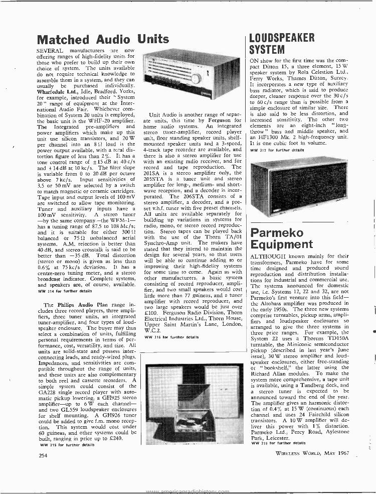
Matched Audio SEVERAL manufacturers :ire now offering ranges of high -fidelity units for those who prefer to build up their own choice of system. The units available do not require technical knowledge to assemble them in a system, and they can usually be purchased individually. Wharfedale Ltd., Idle, Bradford, Yorks, for example, introduced their " System 20 " range of equipment at the Inter- national Audio Fair. Whichever com- bination of System 20 units is employed, the basic unit is the WHF -20 amplifier. The Integrated pre -amplifiers and power amplifiers which make up this unit use silicon transistors, and 20 W per channel into an 8 S2 load is the power output available, with a teal dis- tortion figure of less than 2%. It has a tone control range of ± 15 dB at 40 c/s and ± 14 dB at 10 kc /s. The filter slope is variable from 0 to 20 dB per octave above 7kc /s. Input sensitivities of 3.5 or 50 mV are selected by a switch to match magnetic or ceramic cartridges. Tape input and output levels of 100 mV are switched to allow tape monitoring. Tuner and auxiliary inputs have a 100 mV sensitivity. A stereo tuner -by the same company -the WFM -1- has a tuning range of 87.5 to 108 Mc /s; and it is suitable for either 300 S2
balanced or 75 SI unbalanced aerial systems. A.M. rejection is better than 40 dB, and stereo crosstalk is said to be better than -35 dB. Total distortion (stereo or mono) is given as less than 0.6% at 75 kc/s deviation. It has a centre -zero tuning meter, and a stereo broadcast indicator. Complete systems, and speakers are, of course, available. WW 314 for further details
The Philips Audio Plan range in- cludes three record players, three ampli- fiers, three tuner units, an integrated tuner -amplifier, and four types of loud- speaker enclosure. The buyer may thus select a combination of units, fulfilling personal requirements in terms of per- formance, cost, versatility, and size. All units are solid -state and possess inter- connecting leads, and ready -wired plugs. Impedances, and sensitivities are com- patible throughout the range of units, and these units are also complementary to both reel and cassette recorders. A simple system could consist of the GA228 single record player with auto- matic pickup lowering, a GH925 stereo amplifier -up to 6 W each channel - and two GL559 loudspeaker enclosures for shelf mounting. A GH926 tuner could be added to give f.m. mono recep- tion. This system would cost under 60 guineas, and other systems could be built, ranging in price up to £240. WW 315 for further details
254
Units
Unit Audio is another range of separ- ate units, this time by Ferguson for home audio systems. An integrated stereo tuner -amplifier, record player unit, floor standing speaker units, shelf - mounted speaker units and a 3- speed, 4 -track tape recorder are available, and there is also a stereo amplifier for use with an existing radio receiver, and for record and tape reproduction. The 201SA is a stereo amplifier only, the 205STA is a tuner unit and stereo amplifier for long -, medium- and short- wave reception, and a decoder is incor- porated. The 206STA consists of a
stereo amplifier, a decoder, and a pre- set v.h.f. tuner with five preset channels. All units are available separately for building up variations in systems for radio, mono, or stereo record reproduc- tion. Stereo tapes can be played back with the use of the Thorn TA /Ol Synchro -Amp unit. The makers have stated that they intend to maintain the design for several years, so that users will be able to continue adding to or improving their high- fidelity systems for some time to come. Again as with other manufacturers, a basic system consisting of record reproducer, ampli- fier, and two small speakers would cost little more than 77 guineas, and a tuner amplifier with record reproducer, and two large speakers would be just over £100. Ferguson Radio Division, Thorn Electrical Industries Ltd., Thorn House, Upper Saint Martin's Lane, London, W.C.2. WW 316 for further details
LOUDSPEAKER SYSTEM ON show for the first time was the com- pact Ditton 15, a three element, 15 W speaker system by Rola Celestion Ltd., Ferry Works, Thames Ditton, Surrey. It incorporates a new type of auxiliary bass radiator, which is said to produce deeper, cleaner response over the 30 c/s to 60 c/s range than is possible from a simple enclosure of similar size. There is also said to be less distortion, and increased sensitivity. The other two elements are an eight -inch " long - throw " bass and middle speaker, and an HF1300 Mk. 2 high -frequency unit. It is one cubic foot in volume. WW 317 for further details
Parmeko Equipment ALTHOUGH known mainly for their transformers, Parmeko have for some time designed and produced sound reproduction and distribution installa- tions for industrial and commercial use. The systems announced for domestic use, i.e. Systems 12, 22 and 32, are not Parmeko's first venture into this field - the Altobass amplifier was produced in the early 1950s. The three new systems comprise turntables, pickup arms, ampli- fiers and loudspeaker enclosures so arranged to give the three systems in three price ranges. For example, the System 22 uses a Thorens TD150A turntable, the Miniconic semiconductor pickup (described in last year's June issue), 30 W stereo amplifier and loud- speaker enclosures, either free -standing or " bookshelf," the latter using the Richard Allan modules. To make the system more comprehensive, a tape unit is available, using a Tandberg deck, and a stereo tuner is expected to be announced toward the end of the year. The amplifier gives an harmonic distor- tion of 0.4% at 15 W (continuous) each channel and uses 24 Fairchild silicon transistors. A 10 W amplifier will de- liver this power with 1% distortion. Parmeko Ltd., Percy Road, Aylestone Park, Leicester. WW 318 for further details
WIRELESS WORLD, MAY 1967
www.americanradiohistory.com
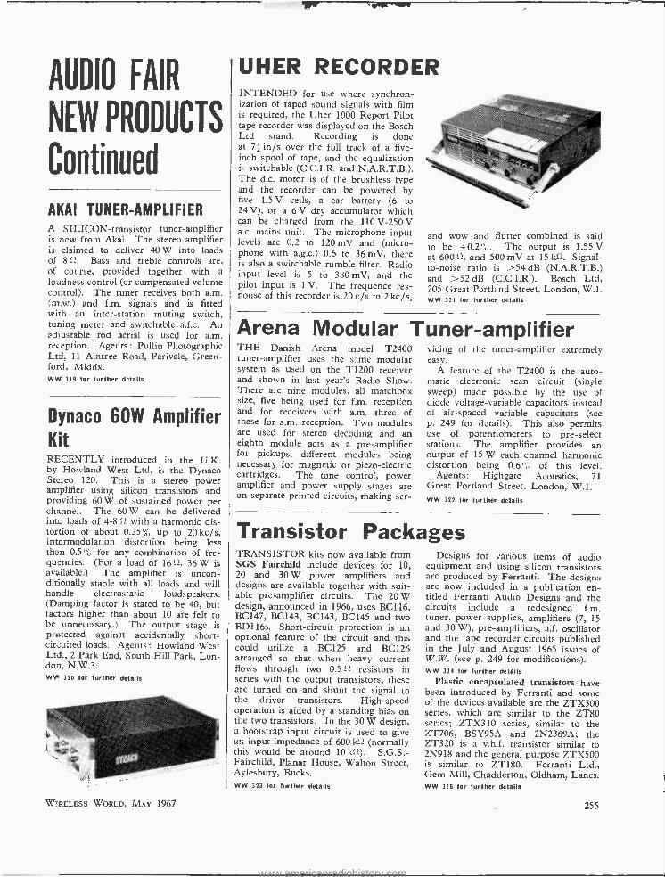
AUDIO FAIR
NEW PRODUCTS
Continued
AKAI TUNER -AMPLIFIER A SILICON -transistor tuner -amplifier is new from Akai. The stereo amplifier is claimed to deliver 40 W into loads of 812. Bass and treble controls are, of course, provided together with a loudness control (or compensated volume control). The tuner receives both a.m. (m.w.) and f.m. signals and is fitted with an inter -station muting switch, tuning meter and switchable a.f.c. An adjustable rod aerial is used for a.m. reception. Agents : Pullin Photographic Ltd, 11 Aintree Road, Perivale, Green - ford, Middx. WW 319 for further details
Dynaco 60W Amplifier Kit RECENTLY introduced in the U.K. by Howland West Ltd, is the Dynaco Stereo 120. This is a stereo power amplifier using silicon transistors and providing 60 W of sustained power per channel. The 60 W can be delivered into loads of 4 -8 12 with a harmonic dis- tortion of about 0.25% up to 20 kc /s, intermodulation distortion being less than 0.5% for any combination of fre- quencies. (For a load of 1612, 36 W is available.) The amplifier is uncon- ditionally stable with all loads and will handle electrostatic loudspeakers. (Damping factor is stated to be 40, but factors higher than about 10 are felt to be unnecessary.) The output stage is protected against accidentally short - circuited loads. Agents: Howland West Ltd., 2 Park End, South Hill Park, Lon- don, N.W.3. WW 320 for further details
WIRELESS WORLD, MAY 1967
UHER RECORDER INTENDED for use where synchron- ization of taped sound signals with film is required, the Uher 1000 Report Pilot tape recorder was displayed on the Bosch Ltd stand. Recording is done at 71 in /s over the full track of a five - inch spool of tape, and the equalization is switchable (C.C.I.R. and N.A.R.T.B.). The d.c. motor is of the brushless type and the recorder can be powered by five 1.5 V cells, a car battery (6 to 24 V), or a 6 V dry accumulator which can be charged from the 110 V -250 V a.c. mains unit. The microphone input levels are 0.2 to 120 mV and (micro- phone with a.g.c.) 0.6 to 36 mV, there is also a switchable rumble filter. Radio input level is 5 to 380 mV, and the pilot input is 1 V. The frequence res- ponse of this recorder is 20 c/s to 2 kc /s,
and wow and flutter combined is said to be ±0.2 The output is 1.55 V at 600 f1, and 500 mV at 151d). Signal - to -noise ratio is >54 dB (N.A.R.T.B.) and >52 dB (C.C.I.R.). Bosch Ltd, 205 Great Portland Street, London, W.1. WW 321 for further details
Arena Modular Tuner -amplifier THE Danish Arena model T2400 tuner -amplifier uses the same modular system as used on the T1200 receiver and shown in last year's Radio Show. There are nine modules, all matchbox size, five being used for f.m. reception and for receivers with a.m. three of these for a.m. reception. Two modules are used for stereo decoding and an eighth module acts as a pre -amplifier for pickups, different modules being necessary for magnetic or piezo-electric cartridges. The tone control, power amplifier and power supply stages are on separate printed circuits, making ser-
vicing of the tuner- amplifier extremely easy.
A feature of the T2400 is the auto- matic electronic scan circuit (single sweep) made possible by the use of diode voltage- variable capacitors instead el air -spaced variable capacitors (see p. 249 for details). This also permits use of potentiometers to pre -select stations. The amplifier provides an output of 15 W each channel harmonic distortion being 0.6'' of this level.
Agents: Highgate Acoustics, 71 Great Portland Street, London, W.1. ww 322 for further details
Transistor Packages TRANSISTOR kits now available from SGS Fairchild include devices for 10, 20 and 30 W power amplifiers and designs are available together with suit- able pre -amplifier circuits. The 20 W design, announced in 1966, uses BC116, BC147, BC143, BC143, BC145 and two BD116s. Short -circuit protection is an optional feature of the circuit and this could utilize a BC125 and BC126 arranged so that when heavy current flows through two 0.512 resistors in series with the output transistors, these are turned on and shunt the signal to the driver transistors. High -speed operation is aided by a standing bias on the two transistors. In the 30 W design, a bootstrap input circuit is used to give an input impedance of 600 k11 (normally this would be around 10 k12). S.G.S. - Fairchild, Planar House, Walton Street, Aylesbury, Bucks. WW 323 for further details
Designs for various items of audio equipment and using silicon transistors are produced by Ferranti. The designs are now included in a publication en- titled Ferranti Audio Designs and the circuits include a redesigned f.m. tuner, power supplies, amplifiers (7, 15 and 30 W), pre -amplifiers, a.f. oscillator and the tape recorder circuits published in the July and August 1965 issues of W.W. (see p. 249 for modifications). WW 324 for further details
Plastic encapsulated transistors have been introduced by Ferranti and some of the devices available are the ZTX300 series, which are similar to the ZT80 series; ZTX310 series, similar to the ZT706, BSY95A and 2N2369A; the ZT320 is a v.h.f. transistor similar to 2N918 and the general purpose ZTX500 is similar to ZTI80. Ferranti Ltd., Gem Mill, Chadderton, Oldham, Lancs. WW 325 for further details
255
www.americanradiohistory.com
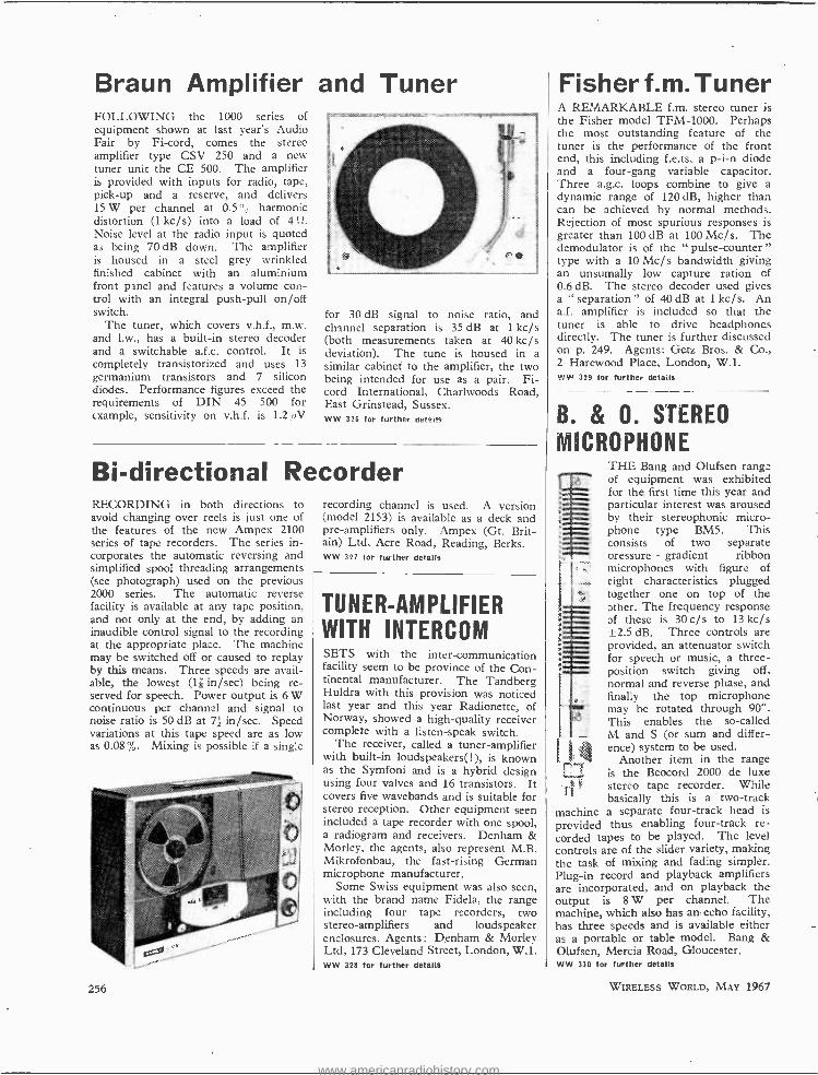
Braun Amplifier and Tuner FOLLOWING the 1000 series of equipment shown at last year's Audio Fair by Fi -cord, comes the stereo amplifier type CSV 250 and a new tuner unit the CE 500. The amplifier is provided with inputs for radio, tape, pick -up and a reserve, and delivers 15 W per channel at 0.5 harmonic distortion (1 kc /s) into a load of 4
level at the radio input is quoted as being 70 dB down. The amplifier is housed in a steel grey wrinkled finished cabinet with an aluminium front panel and features a volume con- trol with an integral push -pull on /off switch.
The tuner, which covers v.h.f., m.w. and l.w., has a built -in stereo decoder and a switchable a.f.c. control. It is completely transistorized and uses 13 germanium transistors and 7 silicon diodes. Performance figures exceed the requirements of DIN 45 500 for example, sensitivity on v.h.f. is 1.2 /4V
for 30 dB signal to noise ratio, and channel separation is 35 dB at 1 kc /s (both measurements taken at 40 kc /s deviation). The tune is housed in a similar cabinet to the amplifier, the two being intended for use as a pair. Fi- cord International, Charlwoods Road, East Grinstead, Sussex. WW 326 for further details
Bi- directional Recorder RECORDING in both directions to avoid changing over reels is just one of the features of the new Ampex 2100 series of tape recorders. The series in- corporates the automatic reversing and simplified spool threading arrangements (see photograph) used on the previous 2000 series. The automatic reverse facility is available at any tape position, and not only at the end, by adding an inaudible control signal to the recording at the appropriate place. The machine may be switched off or caused to replay by this means. Three speeds are avail- able, the lowest (1R in /sec) being re- served for speech. Power output is 6 W continuous per channel and signal to noise ratio is 50 dB at 7z in /sec. Speed variations at this tape speed are as low as 0.08%. Mixing is possible if a single
256
recording channel is used. A version (model 2153) is available as a deck and pre- amplifiers only. Ampex (Gt. Brit- ain) Ltd, Acre Road, Reading, Berks. WW 327 for further details
TUNER- AMPLIFIER WITH INTERCOM SETS with the inter -communication facility seem to be province of the Con- tinental manufacturer. The Tandberg Huldra with this provision was noticed last year and this year Radionette, of Norway, showed a high -quality receiver complete with a listen -speak switch.
The receiver, called a tuner -amplifier with built -in loudspeakers(!), is known as the Symfoni and is a hybrid design using four valves and 16 transistors. It covers five wavebands and is suitable for stereo reception. Other equipment seen included a tape recorder with one spool, a radiogram and receivers. Denham & Morley, the agents, also represent M.B. Mikrofonbau, the fast -rising German microphone manufacturer.
Some Swiss equipment was also seen, with the brand name Fidela, the range including four tape recorders, two stereo -amplifiers and loudspeaker enclosures. Agents : Denham & Morley Ltd, 173 Cleveland Street, London, W.I. WW 328 for further details
Fisher f.m. Tuner A REMARKABLE f.m. stereo tuner is the Fisher model TFM -1000. Perhaps the most outstanding feature of the tuner is the performance of the front end, this including f.e.ts, a p -i -n diode and a four -gang variable capacitor. Three a.g.c. loops combine to give a dynamic range of 120 dB, higher than can be achieved by normal methods. Rejection of most spurious responses is greater than 100 dB at 100 Mc /s. The demodulator is of the " pulse- counter " type with a 10 Mc /s bandwidth giving an unsumally low capture ration of 0.6 dB. The stereo decoder used gives a " separation " of 40 dB at 1 kc/s. An a.f. amplifier is included so that the tuner is able to drive headphones directly. The tuner is further discussed on p. 249. Agents: Getz Bros. & Co., 2 Harewood Place, London, W.1. ww 329 for further details
B. & O. STEREO
MICROPHONE THE_Bang and Olufsen range of equipment was exhibited for the first time this year and particular interest was aroused by their stereophonic micro- phone type BM5. This consists of two separate pressure - gradient ribbon microphones with figure of eight characteristics plugged together one on top of the ether. The frequency response of these is 30 c/s to 13 kc /s ±2.5 dB. Three controls are provided, an attenuator switch for speech or music, a three - position switch giving off. normal and reverse phase, and finally the top microphone may be rotated through 90 °. This enables the so- called M and S (or sum and differ- ence) system to be used.
Another item in the range is the Beocord 2000 de luxe
FT stereo tape recorder. While basically this is a two -track
machine a separate four -track head is
provided thus enabling four -track re- corded tapes to be played. The level controls are of the slider variety, making the task of mixing and fading simpler. Plug -in record and playback amplifiers are incorporated, and on playback the output is 8 W per channel. The machine, which also has an echo facility, has three speeds and is available either as a portable or table model. Bang & Olufsen, Mercia Road, Gloucester. ww 330 for further details
WIRELESS WORLD, MAY 1967
www.americanradiohistory.com

Recorder with Multiplex Filter I SANSUI EQUIPMENT LATEST addition to the Tandberg series 6 tape recorders is the 64X, a three -speed stereo machine. The recorder is a hybrid design using five valves per channel and six transistors. The newly designed oscillator uses tran- sistors and is probably a class D design. Separate 4 -track playback and record heads are used and further, the bias and erase heads are separate, the bias head being termed by some, rightly or wrongly, a cross -field head. (The term cross -field head is also applied to sep- arate heads in Akai recorders, but was originally coined by M. Camras, see p. 129 March 1965 issue.) H.F. response extends up to 20kc /s at 72 in /sec and up to 8 kc /s at 1; in /sec. Multiplex filters are fitted as standard to the re-
corder to avoid beat trouble arising from frequencies above audibility. Signal to noise ratios are given as 62 dB for 7? in /sec and 56 dB at 18 in /sec. (A two - track model will be available later with s/n figures 3 dB better.) A centre channel (left plus right) is included for headphone monitoring from the tape. Agents : Elstone Electronics Ltd, Here- ford House, North Court, Vicar Lane, Leeds 2.
WW 331 for further details
TECHNICAL Ceramics Ltd of Havant, Hants, have been appointed sole U.K. concessionaires for Sansui of Japan. The complete range of Sansui equipment was shown at the Audio Fair and in- cludes mainly a.m. -f.m. tuner -amplifiers, loudspeaker systems and headphones. Distributors: Metrosound Manufactur- ing Co. Ltd, Bridge Works, Wallace Road, London, N.1. WW 332 for further details
STEREO TUNER AND AMPLIFIER FOR stereo sound reproduction, Grundig have introduced the SV40 which comprises mains powered inte- grated stereo pre -amplifiers and power amplifiers. This stereo amplifier has input sockets for magnetic cartridges (3 mV at 47 kfl), for a radio tuner or tape recorder (200 mV at 470 ki2); and a universal input socket for crystal cartridge or additional tuner (200 mV at 1 Mf2). Output is 15 W (continuous r.m.s.) per channel. Channel separation is better than 46 dB, and the frequency response is 20c /s to 20 kc /s ±1 dB.
The RT40 tuner and SV80 amplifier were also shown and have been available on the Continent for some time. The SV80 amplifier incidentally uses 14 transistors per channel and incorporates a presence control, not often found nowadays, and a compensated volume control. New tape recorders are the TK245 and TK220 four and two-track machines incorporating automatic level control circuits. Grundig (Gt. Britain) Ltd, Newlands Park, London, S.E.26. WW 333 for further details
OTHER NEW PRODUCTS Low -cost Cardioid Mike
A NEW microphone from the London Microphone Co. is the LM200, a " dynamic " type with a cardioid direc- tional characteristic. It is claimed to be the lowest priced microphone with a cardioid characteristic (about £5).
It is available in four impedance values (60, 200, 500 f2 and a dual impedance of 50 kf2 and 200 f2). Sensi- tivity at 50 id/ is -50 dB, or 3 mV /µbar, and -80 dB, or 0.1mV /µbar at 60f2. As can be seen from the graph, a front-to- back discrimination of about 20 dB is provided at 1 kc /s. London Microphone Co. Ltd., 182 Camp - den Hill Road, Lon- don, W.8.
WW 330 for further details
o°
lao°
50
WIRELESS WORLD, MAY 1967
100 200 500 1,000 2,000
FREQUENCY (c /s) 5,000 10,000 20,000
" Pulse- counting" F.M. Tuner ONE of the few commercially available f.m. tuners using the so- called pulse - counting technique was seen at the International Public Address Exhibition.
The tuner is based on the W.W. crystal -controlled tuner design, pub- lished in the July 1964 issue. The only major modification is the addition of an a.f. amplifier which will feed into a 600 f2 line. Transistors from the New- market range are used and since a higher -gain type is used in the r.f. stage, sensitivity is increased (to about 8µV fol reliable triggering). The inductors used in the low -pass filter in the i.f. amplifier have been eliminated, no trouble having been experienced as a result. The oscillator is, of course, crystal -controlled and the three crystals are arranged to give an i.f. of 160 kc /s. S.N.S. Communications Ltd., 851 Ring- wood Road, Bournemouth. ww 335 for further details
257
www.americanradiohistory.com
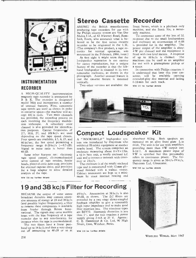
INSTRUMENTATION
RECORDER A HIGH -QUALITY instrumentation magnetic tape recorder is announced by B & K. The recorder is designated model 7001 and incorporates a number of unusual features. First, concentric tape spools are used as shown in order to conserve space -the machine will ac- cept 10_ in reels. Two main channels are provided, the recording process on each involving the frequency modula- tion technique. A subsidiary voice channel is also provided for identifica- tion purposes. Carrier frequencies of 2.7, 10.8, 27, and 108 kc /s are used depending on the tape speed chosen. Four speeds are available, 1.5, 6, 15, and 60 in /sec, the last speed permitting a frequency range 0 -20 kc /s ( -0.5 dB). Signal to noise ratio is better than 48 dB.
Some other features are : electronic tape speed control, electromechanical servo control of tape tension, ferrite heads, photo -electric auto -stop, provision for external capstan drive, and provision for a loop adaptor to allow detailed analysis of the tape.
WW 336 for further details
Stereo Cassette AMONG the British manufacturers producing tape recorders for use with the Philips cassette system are Van Der Molen Ltd., of 42 Mawney Road, Rom - ford, Essex, who announce what is be- lieved to be the first stereo cassette recorder to be originated in the U.K. (The company's first product, a tape re- corder for vertical operation, was announced in the February, 1966, issue.)
At first sight it might seem that the loudspeaker separation is too narrow for stereo reproduction, but a unique feature of the recorder is that the left - hand loudspeaker is situated in its own removable enclosure, as shown in the photograph. Another unusual feature is that the cassette fixture is mounted vertically.
Two other versions are available: the
Recorder Sonic Seven, which is a playback only machine, and the Sonic Six, a mono- only machine.
To counteract some of the loss of l.f. response due to the small loudspeakers and enclosure an accentuation of 6 dB is provided for in the amplifier. The power output of the amplifier is about 4 W per channel and the equipment is fitted with two level meters. A response of up to 10 kc /s is claimed. The machines can be used as an amplifier for use with a gramophone pickup or a tuner.
In connection with Philips cassettes it is understood that later this year cas- setttes will be available carrying extended -play disc material and lasting 6 -10 min for each track. WW 337 for further details
Compact Loudspeaker Kit A "BOOKSHELF" loudspeaker sys- tem was introduced by Daystrom who exhibited Heathkit equipment at another nearby hotel. The system comprises an enclosure measuring about 8 x 9 x 13in, a 63 in bass unit, a totally enclosed h.f. unit and a crossover network with cross- over at 2 kc /s.
The enclosure is of the totally enclosed type and is constructed with 12 mm ply- wood finished with a walnut veneer. Cabinet resonances are kept to a mini- mum by stout internal bracing and
19 and 38 kc/s Filter for Recording BECAUSE the output of some stereo broadcast decoders may contain exces- sive amounts of energy at 19 and 38 kc /s (and possibly higher frequencies), a filter to remove these components is available from Studer through Revox Inter- national. The signals may cause audible beats with the bias frequency of a tape recorder due to any non -linearity, for instance when the tape is overmodulated.
The two filters have a linear pass - band up to 14 kc /s and then a very sharp cut off amounting to 40 dB or so at
258
19 kc /s. Attenuation at 38 kc /s is also 40 dB, as shown. The LC filters are preceded by a two stage direct -coupled feedback amplifier to give a reasonably high input impedance and to make good filter insertion loss. The transistor types are BSY72. Harmonic distortion is less than 1 and the unit requires a power supply giving 2 mA at 25 V. Agents: C. E. Hammond & Co. Ltd, 90 High Street, Eton, Windsor, Berks.
WW 339 for further details
absorbent filling. Both speakers are mounted on an alloy front plate , in thick. The unit is for use with amplifiers providing more than 4W output into 8 -16!1. A maximum power input of- 9 W is specified but this presumably refers to continuous power. The fre- quency range is given as 50 c /s -19 kc /s. Daystrom Ltd, Gloucester.
WW 338 for further details
WIRELESS WORLD, MAY 1967
www.americanradiohistory.com
WORLD OF AMATEUR RADIO
The Mobile Rally Season Opens LAST year, attendances well in excess of 500 were frequently reported at mobile rallies up and down the country. This year, given good weather, the numbers will increase still fur- ther, especially at the large national rallies where upwards of 300 cars can be expected. Today, more than 2,200 of the 12,000 licensed radio amateurs in the United Kingdom are authorized to operate equipment from a moving vehicle and the number is growing monthly.
With the 1967 Mobile Rally season now under way organi- zers, in general, have sought variety in choice of venue. A cliff -top site close to the Viking ship at Pegwell Bay, Rams- gate, Kent, will provide the rallying point for the Thanet Radio Society event on May 7th while the historic Mote House, Mote Park, near Maidstone, Kent, will be the meet- ing place for a rally organized by the Medway Amateur Radio Mobile Committee on June 11th. A week later, on June 18th, the traditional Bucket and Spade party will take place at Hunstanton, Norfolk, where cars from many parts of East Anglia, the Midlands and East Yorkshire will ren- dezvous. On July 9th the close link between the amateur radio and the Boy Scout movement will be further strength- ened when the R.S.G.B. hold its first National Mobile Rally of the season at the Scout camp at Gilwell Park, near Ching - ford, Essex. A record attendance is expected.
Amateur RTTY INTEREST in amateur radio teleprinting is sponsored and encouraged in the United Kingdom by the British Amateur Radio Teleprinting Group whose publication, the B.A.R.T.G. News Letter, is edited by A. W. Owen, G2FUD, 184 Hale Road, Hale, Cheshire. The current issue (36 pages) records an interesting discussion at the Group's recent annual general meeting on RTTY operating speeds, a subject that has caused difficulties in the United States an dsome other countries where amateurs are tied to 45.45 bauds, either by the type of synchronous motor in use or by licensing regulations. U.K. amateurs seem to have overcome the problem of dif- ferent speeds (45.5 or 50 bauds) by the use of twin or dual speed governors. Increased use of narrow -shift keying (170 c /s) is being advocated by the Group's chairman (Robin Addie, G8LT) and others, as it makes for increased receiver selectivity in the presence of heavy interference, although calling for greater receiver and transmitter stability.
To commemorate Centennial Year in Canada, radio tele- printing enthusiasts in the Dominion have formed the Canadian Amateur Radio Teletype Group, to which the call signs VE3RTT and 3C3RTT have been assigned. During Centennial Year Canadian amateurs may use the prefix 3C or the more usual prefix VE.
A.R.R.L. National Convention .-The 16th American Radio Relay League Convention, due to take place in Montreal, Canada, during the period June 30th -July 2nd, will be the first held outside the United States. Details of the extensive Convention programme are available from Douglas Shaw, VE2BSX, 7401 Mount Avenue, Montreal 16, Quebec.
International V.H.F. Convention. -The most important tech- nical- cum -social event for many United Kingdom and Con- tinental v.h.f. /u.h.f. enthusiasts is the Annual International Convention which for the past 12 years has been held in Central London. This year the experiment is to be tried of meeting on the perimeter, with The Winning Post Hotel, Whitton, Twickenham, providing the venue for the 13th Convention on Saturday, May 13th. Talks on field effect transistors, varactors and on how to get going on 2,400 Mc /s, with an A.E.I. film in between, are part of an extensive
WIRELESS WORLD, MAY 1967
programme planned to terminate in the evening with the tra- ditional dinner. Further details of the event can be obtained from the Secretary, R.S.G.B. /V.H.F. Committee, 28 Little Russell Street, London, W.C.1.
I.A.R.U. Region I Division Still Growing. -With the admis- sion to membership of the Radio Society of East Africa the number of subscribing member societies in I.A.R.U. Region I Division is now 24. The R.S.E.A. is one of the oldest established societies on the African continent and while not very strong numerically it has among its 70 members many well -known personalities in amateur radio circles. Head- quarters are in Nairobi, Kenya, and the secretary is Major D. S. Kent, P.O. Box 5681.
Amateur Radio in Turkey. -Although amateur transmitting licences have not yet been issued by the Turkish administra- tion an amateur radio society is flourishing. Latest informa- tion from the Turkish Amateur Radio Club reveals a mem- bership of 600 and about a dozen smaller affiliated clubs. A monthly journal which began three years ago with a few pages and a printing of 1,000 copies now contains 64 pages each month and the printing order has increased to 5,000 copies.
Temporary Licences in Yugoslavia. -News that temporary licences are to be issued to qualified foreign amateurs who visit Yugoslavia will be well received. An application form for a temporary licence can be obtained by writing to the secretary of the Yugoslav National Amateur Radio Society (S.R.J.), P.O. Box 48, Belgrade. When completed the appli- cation form must be returned to S.R.J. together with 10 Inter- national Reply Coupons. Application can be made for a fixed, portable or mobile licence and a YU7 call sign will be issued.
St. Dunstan's Amateur Radio Reunion. -Using the special call sign GB3STD, an amateur station was operated during the weekend April 8th -9th, by a number of war -blinded radio amateurs attending a reunion at St. Dunstan's holiday home and training centre at Ovingdean, near Brighton, Sussex. Host at the inauguration of the station was Lord Fraser of Lons - dale, C.H., chairman of St. Dunstan's who was president of the Radio Society of Great Britain in 1928 and at that time, in spite of his blindness, active as GSSU from his Regent's Park home in London. Also present at the inauguration were A. D. Patterson, GI3KYP, and J. C. Graham, G3TR, respec- tively president and executive vice -president of the R.S.G.B. Among the members of St. Dunstan's who attended were R. L. Vincent, G3TXB, of Cricklewood, London and J. F. Proc- tor, G3JFP, of Rottingdean, Sussex, who, although having the additional handicap of loss of hands as well as of sight, regularly transmit from their own amateur stations.
New Communications Manager. -Following the recent retirement of Francis E. Handy, W1BDI, after 42 years service as communications manager of the American Radio Relay League, George Hart, W1NJM /W3AMR, has suc- ceeded to that office. First licensed in 1930, Hart formed the A.R.R.L. Training Aids section in 1946 and two years later he was appointed assistant to Handy. In 1949 he developed the National Traffic System, later becoming National Emergency Co- ordinator, a post he still holds.
France -California on 144 Mc /s.- Confirmation has been received of a series of two -way 144 Mc/ s contacts by lunar reflection (moon- bounce) between W6DNG Long Beach, California, and F8DO, Bessenay, Rhone. The contacts, the first on 144Mc /s between the West Coast of the United States and France, took place between January 23rd and 27th.
JOHN CLARRICOATS, G6CL.
259
www.americanradiohistory.com
NEWS FROM INDUSTRY
INTERNATIONAL CONSORTIUM TO EQUIP NADGE
A SIX -NATION corporation has been formed to build an air defence warning system for NATO extending from Norway to Turkey at an estimated cost of £100M. This is the largest military electronics project ever undertaken in Europe. The system, which has been called NADGE (NATO Air Defence Ground Environment), will provide fighter aircraft and ground -to -air missiles with an advanced ground con- trol system that will detect, identify, track and destroy enemy bombers.
Shareholding companies of the cor- poration, which is called Nadgeco Ltd., are N.V. Hollandse Signaalapparaten (Netherlands) who will provide gap filler radars and two -dimensional data extractors; Hughes Aircraft Company (U.S.A.) responsible for data processing computers and computer programming;
Marconi Company (U.K.) will carry out improvements to existing early warning radars and also supply height finder radars, manual tracking and reporting posts; Selenia SpA (Italy) will provide data display consoles and the video link for Italy; AEG -Telefunken (Germany) will supply the video link for Norway; and Thomson Houston -Hotchkiss Brandt (France) provide medium power radars some of which will be manu- factured in Denmark and Turkey under sub -contract.
A feature of the NADGE contract is the balance of payments scheme in- volving each of the NATO countries, with the exception of Iceland. This ensures that each country participating in the scheme will receive contracts of equivalent value to that country's con - tribution to the cost of the programme.
EXTRACTS FROM CHAIRMAN'S SPEECH AT E.E.A. LUNCHEON
SALES of radar and navigational aids in the first nine months of 1966 amounted to nearly £60M, over £21M of which was exported. This was stated in a
speech given by the chairman of the Electronic Engineering Association at their annual lunch.
Referring to the visit of Mr. Kosygin and the gift of a u.h.f. radio communica- tions system given to him by the Prime Minister, the chairman stated that it would be a nice thought if this was in- dicative of an enlightened approach to trade in technological products with eastern Europe, and that the Govern- ment will constantly seek to have re- moved from the embargo list those kinds of equipment which have little strategic importance.
In the field of space, with the decision to go ahead with the Black Arrow pro- gramme and from the present ESRO study on behalf of the European Con- ference of Satellite Telecommunications, it is hoped will come a European satel- lite programme. We have heard, he added, suggestions that a single British Authority for space may be set up.
The chairman then went on to say that the Association has welcomed the opportunity, through the Conference of the. Electronics Industry, to put its views to the Fulton Committee on the Civil Service. " We consider it vital that the Civil Service should be manned by people with the right training and out- look so organized as to make an effec- tive contribution to the national good and with the understanding of industry and technology.
The Association view with dismay the
260
importance attached by new graduates to Ph.D courses, and the lack of in- terest in a career in industry of those who have taken such courses, and also the fact that advertisements inviting graduates to remain in universities on courses qualifying for S.R.C. non -tax- able grants are now appearing in con- siderable numbers. " There seems no doubt that a career in industry is in- creasingly ` Non -U.' Part of this fault is our own. We have to convince graduates that problems in industry can be as intellectually stimulating as else- where."
NEW SECURITY ALARM
AN interesting security alarm has been installed in Southampton that links com- mercial premises directly- to the police b; a radio link. A transmitter is in- stalled in the protected premises coupled to the conventional alarm system. This transmitter can send four separate pulse -coded signals each corresponding to a particular type of emergency, burglary, fire, etc. In the event of a power failure built -in bat- teries, that are normally continuously trickle charged from the mains, provide the necessary power. A complex modulation system is used that has been developed to minimise the effect of jamming. The system, which is manu- factured by Halpins of Hampshire Ltd. and distributed in the U.K. by Asso- ciated Fire Alarms Ltd., is subject to a number of patents and because of its very nature further details cannot be divulged.
To replace the existing Pegasus com- puter now in operation at the Science Research Council's Radio and Space Research Station at Slough, an I.C.T. 1905 computer system has been ordered. The 1905 central processor employs a floating point circuit with a primary core store of 16,000 words, backing storage being provided by four magnetic tape units each operating at 20,000 characters a second. Input and output equipment consists of tape and card readers and printers, a 300- lines- per minute line printer and a graph plotter. The equipment will be used for calculating the orbits of artificial earth satellites, processing data from the ionospheric observatories, studies of ionospheric and tropospheric propaga- tion together with other allied tasks.
A contract to install a microwave radio link from Tripoli in southern Greece to Zacros on the island of Crete, a distance of some 450 miles, has been
on by G.E.C. (Telecommunications) Ltd. The route of the new link will be via the islands of Kythira and Antiky- thira. Semiconductors will be used throughout the equipment that for the most part will operate at 6 Gc /s al- though additional circuits on Crete will operate at 7 Gc /s. The main system can carry up to 960 telephone circuits and an automatic failure circuit will allow a standby channel to be used should a working channel fail.
Thorn Electrical Industries and the Bendix Corporation of America are to merge certain of their electronic in- terests and form a jointly owned corn - pany to be known as Thorn Bendix Ltd. which will have a share capital of £750,000. The U.K. companies affected by the merger are Thorn Electronics Ltd., Thom Special Products Ltd., Thorn Electronics (Laboratories) Ltd., Bendix Electronics Ltd. and the M.P.J. Gauge and Tool Company. At the start Thorn Bendix will be con- cerned with electrical connectors, air- craft components, measuring equipment, avionics and defence and industrial elec- tronic equipment. In the future it is envisaged that expansion into allied fieids will take place.
The transformer and circuitry depart- ment of Ferranti Ltd. which is located at Kings Cross Road, Dundee, is to manu- facture under licence from Wabash Mag- netics Inc. of Indiana, U.S.A., a range of resin cast, high- voltage, stabilized power units. The power units have application wherever a high voltage with overload protection is required. The design of the power units is based on ferro -resonant principles which confer in addition to voltage stabilization a current limiting feature. A range of the units is available with voltage outputs of up to 15 kV d.c. at 25 W. Stabiliza- tion is between 0.1% and 7% depend- ing on the nature of the load.
WIRELESS WORLD, MAY 1967
www.americanradiohistory.com
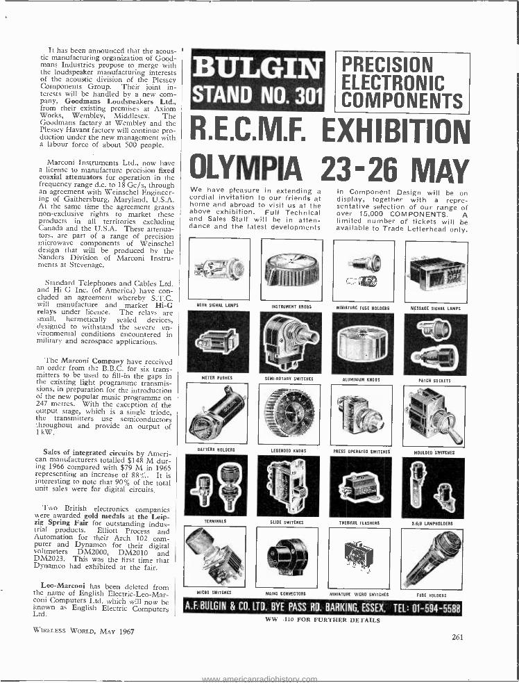
It has been announced that the acous- tic manufacturing organization of Good - mans Industries propose to merge with the loudspeaker manufacturing interests of the acoustic division of the Plessey Components Group. Their joint in- terests will be handled by a new com- pany, Goodmans Loudspeakers Ltd., from their existing premises at Axiom Works, Wembley, Middlesex. The Goodmans factory at Wembley and the Plessey Havant factory will continue pro- duction under the new management with a labour force of about 500 people.
Marconi Instruments Ltd., now have a license to manufacture precision fixed coaxial attenuators for operation in the frequency range d.c. to 18 Gc /s, through an agreement with Weinschel Engineer- ing of Gaithersburg, Maryland, U.S.A. At the same time the agreement grants non -exclusive rights to market these products in all territories excluding Canada and the U.S.A. These attenua- tors, are part of a range of precision microwave components of Weinschel design that will be produced by the Sanders Division of Marconi Instru- ments at Stevenage.
Standard Telephones and Cables Ltd. and Hi -G Inc. (of America) have con- cluded an agreement whereby S.T.C. will manufacture and market Hi -G relays under licence. The relays are small, hermetically sealed devices, designed to withstand the severe en- vironmental conditions encountered in military and aerospace applications.
The Marconi Company have received an order from the B.B.C. for six trans- mitters to be used to fill -in the gaps in the existing light programme transmis- sions, in preparation for the introduction of the new popular music programme on 247 metres. With the exception of the output stage, which is a single triode, the transmitters use semiconductors throughout and provide an output of 1 kW.
Sales of integrated circuits by Ameri- can manufacturers totalled $148 M dur- ing 1966 compared with $79 M in 1965 representing an increase of 88", It is interesting to note that 90% of the total unit sales were for digital circuits.
Two British electronics companies were awarded gold medals at the Leip- zig Spring Fair for outstanding indus- trial products. Elliott Process and Automation for their Arch 102 com- puter and Dynamco for their digital voltmeters DM2000, DM2010 and DM2023. This was the first time that Dynamco had exhibited at the fair.
Leo -Marconi has been deleted from the name of English Electric- Leo -Mar- coni Computers Ltd. which will now be known as English Electric Computers Ltd.
WIRELESS WORLD, MAY 1967
BULGIN STAND NO. 301
PRECISION ELECTRONIC COMPONENTS
R.E.C.M.F. EXHIBITION OLYMPIA 23 -26 MAY We have pleasure in extending a cordial invitation to our friends at home and abroad to visit us at the above exhibition. Full Technical and Sales Staff will be in atten- dance and the latest developments
NEON SIGNAL LAMPS
211 111I1:(IÌ,Í
INSTRUMENT KNOBS
in Component Design will be on display, together with a repre- sentative selection of our range of over 15,000 COMPONENTS. A limited number of tickets will be available to Trade Letterhead only.
MINIATURE FUSE HOLDERS
r4wali METER PUSHES SEMI -ROTARY SWITCHES ALUMINIUM KNOBS
MESSAGE SIGNAL LAMPS
PATCH SOCKETS
BATTERY HOLDERS IEGENOED KNOBS PRESS OPERATED SWITCHES MOULDED SWITCHES
TERMINALS SLIDE SWITCHES THERMAL FLASHERS S.6 8 IAMPHOLDERS
MICRO SWITCHES MAINS CONNECTORS MINIATURE MICRO SWITCHES FUSE HOLDERS
A.F. BULGIN & CO. LTD. BYE PASS RD. BARKING, ESSEX, TEL: 01- 594 -5588 WW -110 FOR FURTHER DETAILS
261
www.americanradiohistory.com
^te,1 (4,4 1
.
Exportese
MORE exports ! " is the order of the day, heard everywhere; from the hustings, from the farthest -flung chair of the Athenaeum Club and, most frequently of
all, from that dreadful illuminated box in the corner of the living room.
But there are exports and exports. There is, for example, washing powder. You can freight that off to darkest Umbopoland and safely leave it to the indigenous shop- keeper to flog it (and its whiteness or brightness message) to the populace.
Not so with capital electronics. With these products the performance you have quoted has to materialize at 110` in
the shade; this means, among other things, that the equip- ment has not only got to be humped to the coral strand (and usually to the most inaccessible part of the hinterland as well) but it also has to be set to work, and that before a given date.
Which brings us to that relatively unknown animal the installation engineer. He is unknown because when you and I are spending a pleasant evening at the local he is squatting on a petrol can in the Kutchi -Kutchi desert desperately scrabbling in the sand for that special bolt which alone can secure the drive capacitor to its moorings. But if in your perambulations through the corridors of power you chance to pass a stranger, prematurely aged and with anti -tetanus serum oozing from every pore, do homage, friend. You have crossed shadows with an installation engineer.
Let us follow the trail of one such. He is at present on his way to the Works Packing Department to supervise the wineglass stencilling ceremony. The general theory behind this ritual is that wineglass symbols, if stencilled vertically on the sides of packing crates, serve as a sign to dockers the world over that this is the right way up. In practice the method is an infallible means of enabling dockers to load or unload the crates in the absolute certainty that they are all upside down.
The ceremony over, forty crates lie ready for despatch to
Umbopoland. They are going at the behest of the Ministry of Defence, who want a Mark IX radar installed in a certain strategic position and as Umbopoland is in that position, and on our side, that country has been prevailed upon to buy one.
" The sad vicissitudes of things" The scene now shifts to the quayside at Tsetse -Tsetse, Umbopo:and's only port. The installation engineer is there, having flown out with an unofficial overnight stop in Cairo, of which more anon. The crates are also there; four of them disgorging green mud and sea -water by reason of a slight miscalculation in the unloading process and a further two otherwise the worse for wear because two Umbopan crane - men have whiled away a dull morning by playing conkers with them.
According to H.Q. information the entire might of the Umbopan Ministry of Transport should also be on the quayside and straining at the spark plugs to carry the white man's burden. In actuality the quayside is barren of wheeled traffic; enquiries reveal that the whole might (which turns out to be one war -time half- track) is presently in
262
1f
YCz!,el"
attendance upon His Highness the Midriff of Umbopoland who is away on safari and is not expected back for some weeks.
But the installation engineer, true to type, is a man of resource. Finding that mules are available in quantity he hires a sizeable team of these animals complete with carts, and loads up. Those readers who have been unfortunate enough to have dealings with mules do not need to be reminded that it is one of life's less fragrant experiences. So, in the mules' good time our hero sets off for the site some 120 miles away, one hand clutching a brief -case con- taining his precious working drawings. The broad concrete highway gives up the struggle after a short distance and reverts to unclassified track.
A fortnight and three mules later he reaches journey's end where, he has been told, a strong Umbopan labour force is putting the finishing touches to the station buildings. In fact the sole inhabitants are an ancient gentleman called Abdul Bilbaley Jones and a 1928 Buick, with a broken half - shaft. The human half òf this dynamic duo states on oath that the working party have adjourned to a fiesta in the capital 50 miles to the south. When will they be back? Abdul raises a finger heavenward to indicate that the answer is beyond human power to give. Tomorrow, perhaps? Or before the rainy season? Or perhaps after the rainy season? Who knows? The installation engineer glares at the roofless station buildings and goes blasphemously to bed.
But worse is to follow. On opening his brief -case the following morning he finds, not his working drawings, but a volume entitled " The Air Hostesses' Manual." At precisely the same moment in a flat in faraway Cairo, an air hostess is sitting gazing in some perplexity at a wad of blueprints marked SECRET which has somehow materialized at her bedside in place of her vade mecum. How the two came to change places is no part of this story.
Hastily despatching a mule and rider to civilization with a panic- stricken cable, the engineer gets down to business. Deciding that the labour force is unlikely to return until after the rains he recruits the mule drivers to the cutting down of jungle brushwood and after a week's arduous toil succeeds in fashioning a very passable thatched roof on one of the station buildings. He can now ge' the equipment unpacked. At that moment the rain begins to pest down. Simultaneously the Umbopan equivalent of "Knees up Mother Brown! " is
heard from without and the errant labour force staggers into the compound. With considerable joie de vivre it proceeds to tear off the temporary roof ... .
It is truly the installation engineer's darkest hour. But on the morrow his luck turns when, inside one of the crates, he finds a complete set of working drawings. Two months later the station is completed, 24 hours inside the contract date and working better than spec.
It is at this juncture that a helicopter teeters down. It contains the British Ambassador, no less. It seems that there's been a revolution in the capital and the mob now in
power are anti -Us and pro You- Know -Who. So he's afraid, old boy, that there's nothing for it but to blow this contrap- tion up. Ministry orders and all that ... .
As I said, there are exports and exports.
WIRELESS WORLD, MAY 1967
www.americanradiohistory.com
MAY, 1967 Wireless World iii
SOLDERING EQUIPMENT
`THERE IS NO SUBSTITUTE
FOR A SOLDERED JOINT"
Where extreme reliability was
required, 1,300 joints to last 20
years on the sea -bed, Adcola
Soldering Instruments were
specified for consistent efficiency.
Photograph by courtesy of STANDARD TELEPHONES & CABLES LTD.
For full information
and sales apply direct to
HEAD OFFICE SALES & SERVICE
ADCOLA PRODUCTS LTD ADCOLA-HOUSE, GAUDEN ROAD,
LONDON, S.W.4.
Telephones: 01-622-0291/ 3 Telegrams: SOLJOINT, LONDON, S.W.4
AUSTRALIAN ASSOCIATES: ADCOLA PRODUCTS PTY. LTD., 673 WHITEHORSE ROAD, MONT ALBERT MELBOURNE AGENTS IN ALL LEADING COUNTRIES
www.americanradiohistory.com
iv Wireless World MAY, 1967
"AN
Why d g overseas electron s anufacturers use Ersin Multicore Solders
Because they realise that their reputation can rest upon the quality cf the solder they use. For utmost reliability they use Ersin Multicore, the only solder containing the purest tin and lead, plus 5 cores of extra -active, non- corrosive Ersin flux. Whatever the application - the speedy soldering of miniature components or the individual production of large units - there is an Ersin Multicore Solder which is exactly right for the job.
CANADA Ersin Multicore 5 Core Solder being used to solder Philco Auto Radios at the Philco factory, Don Mills, Ontario, Canada.
HOLLAND Ersin Multicore 5 Core Solder is used for soldering printed circuit boards by N. V. Eminent, Bodegraven, Holland.
DENMARK Ersin Multicore 5 Core Solder being used for the manufacture of high quality electronic instruments at the factory of A/S Brüel & Kjaer, Naerum, Denmark.
NEW ZEALAND Ersin Multicore Savbit Alloy is seen being used at the factory of the Bell Radio Television Corporation Ltd., Auckland, New Zealand.
IN DIA A motor being assembled with Ersin Multicore 5 Core Solder in the factory of M/S A.E.I. Manufacturing Co. Ltd., Calcutta, India.
THE QUEEN S AWARD TO INDUSTRY 1966
FINLAND Ersin Multicore 5 Core Solder being used in the hand soldering of printed circuit boards for Television Receivers on an assembly line at a factory in Finland.
> reliabilitÿ See us at the Electronic Components Show, May 23rd to 26th on Stand No. 154. Turn right when entering show to see new developments applicable to soldering. MULTICORE SOLDERS LTD.. Hemel Hempstead. Herts. Telephone: Hemel Hempstead 3636. Telex: 82363.
WW-002 FOR FURTHER DETAILS
www.americanradiohistory.com


