MEASUREMENT OF FLOW AND DIRECTION OF GROUND WATER BY RADIOACTIVE TRACERS: HYDROLOGICAL EVALUATION OF A WASTE DISPOSAL SITE AT "INSTITUTO DE PESQUISAS ENERGÉTICAS E NUCLEARES (IPEN)" U. Ctundra, P. E. Aoki, J. A. Ramo» • Silva • A. C. Castagrwrt PUBLICAÇÃO IPEN 28 IPEN - Pub • 28 MAIO/1981
Transcript
MEASUREMENT OF FLOW AND DIRECTION OF GROUND WATER BY
RADIOACTIVE TRACERS: HYDROLOGICAL EVALUATION OF A
WASTE DISPOSAL SITE AT "INSTITUTO DE PESQUISAS
ENERGÉTICAS E NUCLEARES (IPEN)"
U. Ctundra, P. E. Aoki, J. A. Ramo» • Silva • A. C. Castagrwrt
PUBLICAÇÃO IPEN 28
IPEN - Pub • 28MAIO/1981
CONSELHO DELIBERATIVO
MEMBROS
Dr Luiz Cintra do Prado - Presidente
Dr Edgardo Azevedo Soarei Júnior — Vice- Presidente
CONSELHEIROS
Dr Hélcio Modesto da Costa
Or Ivano Humbert Marches'
Or Waldyr Muniz Oliva
REPRESENTANTES
Dr Jacó Charcot Pereira Rios
Dr. Samuel Angarjta Ferreira da Silva
SUPERINTENDENTE
Hernani Augusto Lopes de Amonm
PUBLICAÇÃO IPEN 28 MAIO/1981
IPEN Pub 28
MEASUREMENT OF FLOW AND DIRECTION OF GROUND WATER BY
RADIOACTIVE TRACERS: HYDROLOGICAL EVALUATION OF A
WASTE DISPOSAL SITE AT "INSTITUTO DE PESQUISAS
ENERGÉTICAS E NUCLEARES (IPEN)"
U. Chandra, P. E. Aoki, J . A. Ramos e Silva e A. C. Cattagnet
CENTRO DE APLICAÇÕES DE RADIOISÓTOPOS E DE RADIAÇÕES NA ENGENHARIA
E NA INDÚSTRIA - CARREI
AREA DE APLICAÇÕES KA PRESERVAÇÃO E APROVEITAMENTO DE RECURSOS NATURAIS
INSTITUTO DE PESQUISAS ENERGÉTICAS E NUCLEARES
8AO PAULO - BRASIL
Série PUBLICAÇÃO IPEN
INIS Categories and Descriptor*
B32
0 24
DILUTION: Measuring methods
VELOCITY: Ground water
TRACER TECHNIQUES: Ground water
FLOW RATES: Hydraulics
GROUND WATER Radioactive tracers logging
RADIOACTIVE TRACERS LOGGING: Measuring methods
MEASURING METHODS: Radioactive tracers logging
WASTE DISPOSAL: Hydrology
RADIOACTIVE WASTE DISPOSAL- Ground water
GROUND WATER: Radioactive waste disposal
CARREI-AAPARN
Received in October 1980.Approved for publication In March 1981.(Writing, orthography, concepts and final revision art of exclusive responsibility of trie Authors.
MEASUREMENT OF FLOW AND DIRECTION OF GROUND WATER BY
RADIOACTIVE TRACERS: HYDROLOGICAL EVALUATION OF A
WASTE DISPOSAL SITE AT "INSTITUTO DE FESQUISAS
ENERGÉTICAS E NUCLEARES (IPEN)"
U. Chandra, P. E. Aofci, X A. Ramo* e Silva • A. C. Cwtagrwt
ABSTRACT
vtldescribe^fhe method of determining flow and direction of ground matar by using radioactive tracer»
in ground water bormgHTVanou» parameters controlling the measurement» are discussed in detail. Application of the
method in studying Variety of gaohydrological problemsibac-aeen indicated. Comparison of the method with conventional
The first application of the borehole dilution technique by Centro de Aplicações de Radioiiotopos e Radiações na"Engenharia e na Industria (CARREI) was made to study the movement of ground water around the radioactive wast*
disposal site at Instituto de Pesquisai Energéticas e Nucleares (IPEN). A study of geohydrclogical evaluation of the disposalsite has been made. Field experiments in the nearest available monitoring well 850 m downstream were made to determineflow and direction of ground water movement. ' ' I and * Br were used as radioactive tracers for flow measurements,while S ' CrCl3 was used as an absorbing type tracer for determining direction of flow. The field equipment used consistedof gramma scintillation probes, sealer count rate meter, isotope injection assembly and extension rods. Natural gamma logof the well was taken to verify the construction of the borehole and to have an idea of geological stratification at the site.Estimates of velocity of ground water at the waste disposal site were made and therefrom travel times of radioactivenudides relative to local ground water were computed.
The average filtration velocity at 850 m downstream of the waste disposal site has been found to be 3.66 cm/d.
The local direction of ground water is towards old Jaguaré stream.
Based on the estimates of bulk density 1.8 g/cm3. porosity 36%, distribution coefficient 1000 for 1 3 7 C end 30for '°Sr, following analysis regarding the radioactive waste disposal site at IPEN has been nade:
Filtration rate of ground water - 6.48 cm/d
Stage speed of ground water =18 .6 cm/d
Arrival time of ground water uptonearest point of old Jaguaré canal = 2431 d
Velocity of radionudida)131Cs)= 1 .94x10" '
Velocity of ground water
Velocity of radicuiclidaf °Sr)• = 6.44 x 10"J
Velocity of ground water
The values of field permeability determined are as following:
determined by radiotracer technique = 3.26 x 10~3 cm/»
determined by pumping tests = 8.60 x 10~* cm/l
1 - INTRODUCTION
Radioactive isotopes are normally used as tracers to determine local hydrological characteristics,viz.. direction and speed of ground water flow; stratification of aquifer, its porosity and transmissivity. Theradioactive tracers are used in ground water investigations via the single1 and multiwell methods'1'. Insingle well method, the velocity and direction of ground water flow are generally ascertained from a singleborehole drilled in the area of investigation.
The present report reviews the technique of single well method and reports some of theinvestigations carried out for hydrological evaluation of a radioactive waste disposal site at I PEN.
2 - DETERMINATION OF VELOCITY OF GROUND WATER
One of the important parameter in ground water investigations which needs to be determined isthe filtration velocity, v f, as defined by Oarcy's law;
vf = k3 . I (1)
where k3 is the permeability of the aquifer and I is the gradient head of the ground water flow. Filtrationvelocity vf can also be measured from the stage speed V between two boreholes and effective porosity inpumped or unpumped aquifer i.e..
vf = n . V (2)
2.1 - Principle of the Single Well Method
A direct neans of determining filtration velocity is the dilution method. In this method, the waterin a borehole is labelled with a tracer solution, and the dilution of the labelled water by inflowing groundwater is measured. The dilution rate of the tracer, which is homogeneously distributed in a volume V in theborehole, is described by a differential equation, the solution of which renders the relationship:
Vv = In c/Co (3)
8 Ft
where
va = apparent velocity;
V = measuring volume (the volume in which dilution takes place);
F = area of cross section of the measuring volume perpendicular to the direction of flow;
t = time interval between measurement of concentration Co and c.
The horizontal flow pattern in the aquifer is distorted owing to the presence of a borehole anddifferent flows there in. Thus, the measured velocity in the borehole (v#) is'related to the actual filtrationvelocity (vf) by additional flow terms, which account for the distortion of the natural flow field.
Thus:
vt = a . vf + v£ + vv + vm + vd (4)
where.
v = apparent filtration velocity caused by density 6ffec« (concentration, temperature, etc.);
v = apparent filtration velocity caused by vertical currents;
vm = apparent filtration velocity caused by artificial mixing;
v. = apparent filtration velocity caused by molecular diffusion of the tracei.
The correction factor o which accounts for the distortion of the flow lines owing to the presenceof the borehole, is defined by
<VQb (6)
where Qa is the horizontal flow rate in the borehole and Q^ is the flow rate in the same cross section of theformation (i.e. in the absence of the borehole).
In the absence of all other flows but horizontal:
Vv, = Inc/Co (5a)
f «F t
wriv, = In c/Co (5b)
f 2ot
2.2 - Borehole Construction and Calculation of a
Normal construction of a borehole consists of a perforated filter tube surrounded by a gravelpack. If the borehole of radius r3 has a filter of external and internal radius r} 6 r, and if the respectivepermeabilities of the f i l f r tube, gravel pack and the formation are k,, k i and k3 (Figure 1).then, application of the potential theory to this borehole, gives the following expreMion for a: 1 •
formula138».In the absence of a gravel pack. ra = r, and k} = k3. and tha equation (6) is reduced to Ogilvi's
1 • ( r . / r , ) 1 + k,/k, [ 1 - ( n / r , ) 1(7)
2.3 - Filter Tube Permeability
Various designs of the filter tubes which can be recommended for installations are shown inFigure 2. The permeability of the filter tube k, can be measured from experimental as well as theoreticalmodel test'29 . Model experiments with various types of filter tubes have revealed*10> that the valueof k| was independent of the type of filter used, the thickness of the filter tube and k2 , r3 , k3 . ln most ofthe cases. 10% perforations in the filter tube are sufficient even for permeable materials . However, forhighly permeable, coarse gravels, perforations to the extent of 20 — 30% are recommended.
2.4 - Permeability of the Gravel Pack and Aquifer
According to the equation (6) and (7), the permeabilities of the aquifer, k3, and of the filtergravel, k7, must be know for a calculation of ft — value. On the other hand, it is often precisely thek3-value that is to be determined with the aid of filtration velocity. To examine this basic question ofapplicability of the method, a was calculated by equation (6) as a function of the parameters k2/k, andk3/k2. (Figures 3 -7 ) show the results of computer calculations'18-101 made from Equation 6. Theconclusion drawn from these studies is that a remains independent of the parameters kj /k| and k3/k2 anddepends only on the radii r,, r2 and r3, and hence can be calculated with sufficient accuracy (10%). if theconditions.
k, > k3 > 10 . k3 (8)
are fulfilled.
In practice, it is revealed that the condition 10 . k3 < k2 is satisfied in most of the cases. If thecondition k, > k2 is not satisfied, a must be calculated from the values of k, and k3 by Equation 6. Forthis purpose, the permeabilities k, and k2 will have to be determined by laboratory tests or taken from theavailable literature'291 The permeabilities k, and kj should ensure a sand free entry of the ground waterinto the filter tube i.e., the grain size of the gravel filter must be large than the perforations of the filtertube. Further, the filter grai/el should be so selected that the gravel filter will retain the sand-gravelmixture of the ground water duct, but at the same time allow a desanding of the well. These perequisitesare mostly met for example by German Industrial Standards and empirical data adopted in wellsinking'3'. It is advisable to clean the borehole before experiments, to remove material accumulated inthe filter tube.
For the case of the borehole without gravel filter Figure 8 and 8 derived from equation (7), showthat a is independent of k, for k, > > 10 k j . In the event that k, = k3 (i.e. the worst case), a maximumdeviation of 20% for a must be taken into account. This is admissible teeing the range of accuracy requiredin practice.
2.6 - Effect of Ttmr Diffusion
Equation (4) shows that the diffusion of the tracer plays a part in determining dilution rate va- Atracer concentration may eliminate density effects but does not eliminate diffusion of the tracer. Even inthe absence of ali other interfering parameters, diffusion always exists, but its influence diminishes as vf
increases. Matvejev showed that the diffusion velocity v . may be estimated from trie relationship
vd = = 10~5 cm/s = 0.01 m/d
where; 0: diffusion coefficiente of the tracer and r,: inner radius of the filter tube.
Laboratory model experiments'18' have shown that diffusion effects do not become significantfor v, > 0.3 m/d, whereas for vf < 0.3 m/d a correction may be applied according to the relation:
va " vd(9)
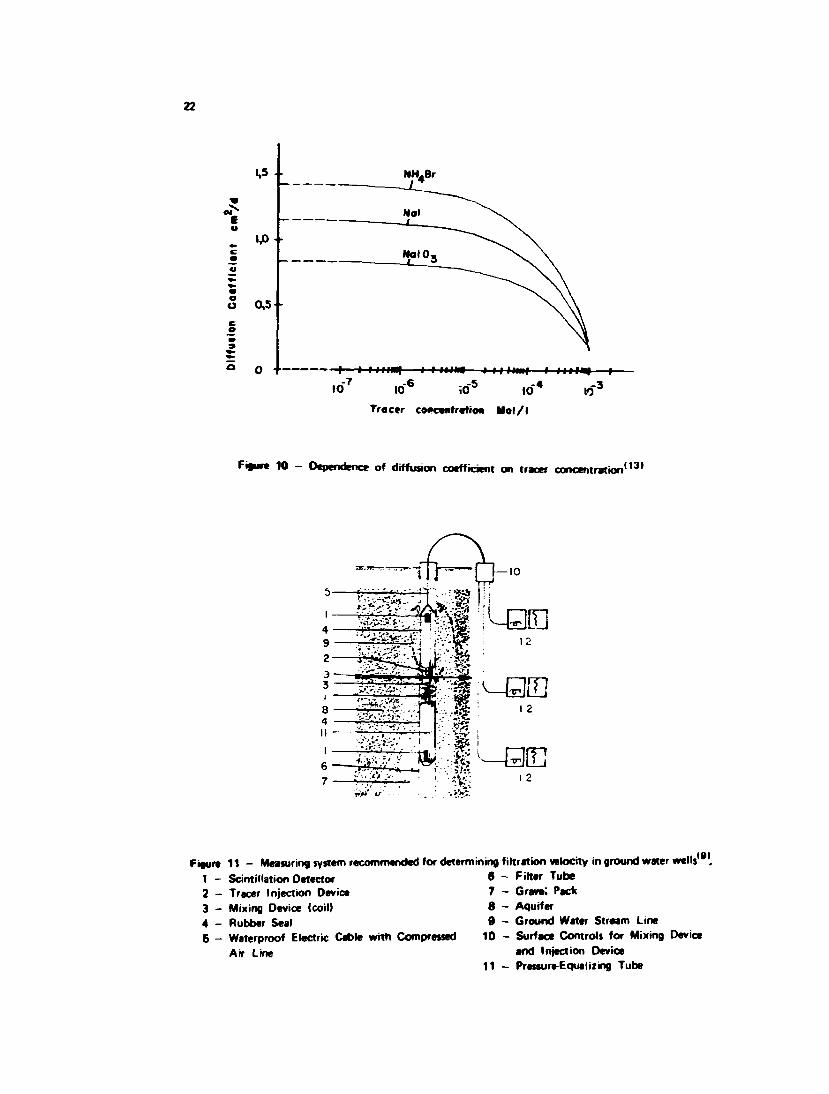
provided there are not other disturbing parameters (i.e., v . v , v are negligible). Without a correction fordiffusion, the ratio of the dilution velocity to filtration velocity, in the range of v( < 0.3 m/d. tends *o growrapidly with decreasing filtration velocity. Model experiments'10 ' have shown that vd> for v( - 0, is about 3to 4 times greater than the one calculated on the basis of equation (9); therefore, for field tests v . = 3jrD/r,may be taken as an approximation. The variation of diffusion coefficient with tracer concentration ' isshown in Figure 10 for ready reference.
2.6 - Effect of Probe Dimensions
A correction in the dilution volume in the equation (5) due to the volume of the detector probe,n
becomes:
197 051
has been suggested by various workers ' . If the detector probe has a radius rQ, then equation (5.b)
2an tIn c/Co 110)
Experiments have shown that a - value remains independent of ro/r, within the range of0 < r Q / r , < 0.92. When the diameter of the probe is large relative to borehole diameter, the measurementtime is reduced but the flow may be distorted. Large diameter probes are apt to be more influenced bytracer absorption on the walls and by the tracer outside the measuring volume. It is preferable to use aprobe whose diameter does not exceed half of the filter tube diameter.
2.7 - Effect of Mixing
The derivation of the equations (3), (5) and (10) is based on the assumption that the distributionof the tracer throughout the measuring volume is uniform at all the times. In case of incomplete mixing ofthe tracer in the dilution volume, no unambiguous exponential dilution results but rather twosemi-logar thmic straight lines of different slopes are often encountered. Only with filtration velocities lessthan 0.3 m/d does the molecular diffusion of the tracer suffice to distribute the tracer homogeneously
throughout the dilution volume. I n many cases a concentration gradient is produced through adisplacement of the labelled water column by the detector centred in the measuring volume. As a rule, theinitial part of the dilution curve obtained can be discarded for calculation purpose, because of incompletemixing or residual currents.
Therefore, it is necessary, in general, to provide for an artificial mixing of the tracer in the dilutionvolume by a mixing device. The mixing device generally consists of a wire coil rr oved up and down. Uniquevf value can be attained only above a minimum mixing rate. This mixing rate depends on the filtrationvelocity and on the a - value. Too intense mixing, may. especially if very samall velocities are involved,lead to additional disturbance of the flow field or forcing the tr*. tr out of the measuring volume.
2.8 - Effects of the Vertical Flow in Fifnr Tub*
Vertical flow may result in the measuring volume when the ground water flow lines are notperpendicular to the borehole'31' or when the borehole penetrates stratified water bearing formations. Thisvertical flow consequently increases the dilution velocity and a correction must be allowed for calculatingvf. This correction in practice is not possible because it is not readily possible to determine the verticalflows. However, it is possible, through technical measures, to minimize the vertical flow such that they donot disturb the measurement results. To eliminate vertical flow within the filter tube, use of packers to sealthe top and bottom of the dilution volume has been suggested by various workers'16 '27-15 ' . Model andfield experiments have proved that even the reals do not fully prevent the influence of vertical movement ofthe water. The water bypasses the sea!» through the gravel pack, enters the measuring volume and disturbsthe measurements. Perhaps in uncased borehole in hard rocks, it could be possible to stop vertical flow byusing seals.
Seals should increase the resistance for vertical currents such that the horizontal flow Qh throughthf dilution volume substantially outweighs the vertical throughflow Qy (Q^ > > CH. Figure 11 shows afiltration velocity measuring system used by Instituí fur Radiohydrometrie. Above and below themeasuring volume is a seal in which detectors are fitted to monitor possible vertical flow immediatelyoutside the filter tube . If ground water retains its original direction of flow after passing the measuringvolume, the filtration velocity can be determined by the equation (5). If, on other hand, the flow isdiverted from its original direction into a vertical flow, as show in Figure 11, then according to equation(4), the dilution velocity is
where Qg >s the total ground water discharge in the measuring volume as determined from equation (3). Ifthe vertical discharge Qy is approximately determined from the relation.y i
Lf f l r l - r\)n
where L it the mean distance of the measuring volume from the detectors (Figure 11), t is timeof flow over the distance L, r3 is radius of the borehole, r, is external radius of the filter tubeand n is porosity of the gravel pack.
By determining the difference Q ( - Qv. the horizontal flow and hence the filtration votocity canbe determined by equation (6 b).
In the presence of the vertical flow, tht dilution method can be used for determination of the
filtration velocity only when the horizontal discharge is considerably greater than the vertical discharge in
the filter tube-
Since the cross-section for the vertical flow is usually much smaller than ti.e horizontal one.
vertical velocity may be of the same orcer of magnitude as the horizontal velocity. v f. without significantly
interfering with the measurement of vf l 7 \ Since the flow resistance is basically controlled by permeability
and the length of gravel pack through which water flows around the seal, the length of the seal certainly
will influence its effectiveness. Long seals compared to the length of the dilution volume may cause a
disturbance of the two-dimensional flow field and thereby increase the a - value. Model and field tests have
shown110' that with seals of length 10 and 25 cm and a length of 25 cm of the dilution volume, the
increase of a - value amounted to about 10%.
With measuring devices provided with seals, filtration velocity in a borehole can be measured atvarious depths. Measurements at several depths can thus take considerable time. In earlier measurements offiltration velocities by rfiUition method, the entire water column of the filter tube was tagged withradioactive tracer and tne decrease in its concentration was then measured as a function of depth . Thisway, the time required for logging the filter tube is reduced, but the interpretation of results is oftendistorted by the exitence of the vertical flows. To correct this, separate injections of tracer can be madeto determine upward or downward vertical currents. From the vertical flow patf and flow time of tracer inthe filter tube, vertical flow velocity and hence vertical discharge can be determined. Subtraction ofvertical discharge from total discharge obtained from equation (5.a(, yields the horizontal filtrationvelocity. With this method, however, not all measurement conditions for vf determination can be fulfilled;as a check, therefore, it is necessary to carry measurements with seals at a few points.
The decrease in concentration of the tracer solution (i.e., the counts of detector) can be recordedat surface in digital or analog form, so that they can be fed into a computer if possible. If no computer isavailable, it is advisable to plot the concentration decrease semilogarithically against time. The slope of theline is proportional to the filtration velocity.
2.9 - Velocity Range, Error Involved, Cost and Validity Conditions
The lower limit of measurable velocity by dilution method lies in the range of diffusion velocityi.e. about 1 cm/d. Upper limit of measurable velocity is turbulent flow for which theory for estimation of ahas not been developed. Practical upper limits depend upon instrumentation and technique (i.e., response,mixing, recording ability, etc.). Field experiments have reported velocities upto i20m/d under pumpingconditions and 10-20 m/d under natural gradients.
Error in the value of vf is determined basically by the uncertainty involved in the a - value. Acareful construction of the borehole with right choice of filter tube and the surrounding gravel pack isessential condition for accurate application of the dilution method. Experience shows that in mostinstances there is lack of dependable supporting site information and thus it becomes difficult to ascertainthe results of the dilution method. Model experiments show that uncertainty in permeability value of thefilter tube and gravel pack leads to an error in a and vf of about 10% if equation (8) is fulfilled. Underunfavorable field conditions, the dilution method can be expected to give about 50% accuracy for absolutevalues of filtration velocity.
vf
hydrological problems, measurement technique and radiation protection. The cost of a single vf
measurement is made up of personnel, travelling, transport arid equipent costs. Further, the cost dependson the number of the wells in the ground water field and the number of measurements required.
Borehole dilution method is best suited to homogeneous formations lite aNuvial jravel and sands.In the presence of significant vertical flows or in fractured end kanbc rocks tfie results or dilution methodsere utMizabie nomwlly only qualitatively. Even Qualitative measurements era of immense practicalimportance in investigations of ground water.
The results of dilution method in a borehole in principle can be extrapolated to surroundingaquifer. This extrapolation is valid in all cases where there is horizontal flow all along the depth. If * eaquifer is composed of broken or dislocated layers, tht net work of borehole must be closer to gatherreliable data applying to the entire ground wafer field.
Certain advantages of the borehole dilution method can be listed as following:
- tht investigation can be carried out in unpumped ground water and therefore give the flowrate of the unstressed aqu'fer;
- if proper well construction is executed, detailed information on the stratification of theaquifer ca.i be obtained;
- the measurement can be performed in boreholes of any diameter O1.5") ;
- it is economical to determine ground water velocity by the method.
2.10 — Comparison of Diliition MeeJiod wHfi PMNpeag Tcvtt
Using the dilution method one can determine the filtration velocity (Le., Oarcy velocity) and ifgradient is known, the permeability of the aquifer k3 can be determined. The traditional methods ofdetermining the k3 value are pumping tests and in-situ packer tern. It is interesting therefore to compar*the dilution method and the conventional pumping tests for ascertaining the extent to which these methodsconfirm and complement each other. Following points ara worth mentioning while a relative comparison oftrie methods is attempted.
2.10.1 - The calculation of k3. bated on Darcy's law in all casts require that the ground watergradient head I at the test site be known. The determination of I from the ground water levels in gauges,which appear simple in principle, can become problematic if, observation net work is not d o » enough; theground water is stressed, gauges »-e at different pressures or if foundations of structures penetrate theground water zone.
2.10.2 - The zone of influence in the aquifer for which the kj values are derived by dilutionmethod and the conventional pumping methods, differ considerably. Vertically the dilution method canlog each individual strata. The packer testi furnist. an average k3 value around the bottom of the bcrehotewhereas pumping tests yield a kj value which applies to the ertire thickness of the aquifer tapped by theboring. Horizontally, the zone of influence for the various methods in relation to the filter tube diameter.2f|, can be approximately expressed as:
a . 2r( for dilution method;
IOTI for packer tests;
10 - 103 r, for pumping tests (depending upon type of measurement).
In dilution method stream line density of ground water is meatured in the horizontal planewhereas in pumping tests both horizontal and vertical planes are involved.
It can be said that k3 - values determined by dilution method and packer tests are more readilycomparable. In comparasion of dilution method and large area pumping tests, agreement will be obtainedonly if the measuring points of the dilution method are representative of the entire ground water duct. Ingeneral, however, maximum ka - values obtained by dilution method can be expected to be higher thank3 - value furnished by pumping test, since thin layers of lesser permeability do not effect the dilutionmethod due to the presence of gravel pack:
2.10.3 -Water levels, discharges and other field conditions which normally change with time,should be comparable while the results of various methods are analysed. It may often occour thatmeasuremnnt results of a pumping test, dating far back and conducted under other or unknown conditions,are the only ones which are avialable for comparison purposes.
Ir. short, it can be summarized that undispu table comparisons between different methods to
determine k3 - value are possible only under favorable field conditions.
Systematic dete.minations of k3 - value, first by packer tests and then by dilution method, were
carried out in Germany in the past. Packer tests were conducted by installing filter nozzle at various bottom
depths during sinking of a well. The k3 - value was ascertained by small scale pumping experiment under
hydrostatic or dynamic method1331. Altogether, 38 measurements were carried out in the alluvial coarse
gravels. The agreement between the pair of measured values was up to 85% .
Gaspar et a l . " 4 ) carried out measurements in sands and gravels, and the results of dilution method
agreed well with those obtained from pumping experiment Similar comparative measurements were
reported by Milde1361 , Kratzschmar1301, Drost et a l . 1 1 0 1 and l f R ( 1 8 t 9 ' 2 1 * and in all the cases the data
obtained for coarse gravels gave satisfactory results.
In the light of this, it can be said that the dilution metnod can provide substantially the same
results as the usually very onerous pumping experiment'.
3 - DETERMINATION OF DIRECTION OF FLOW OF GROUND WATER
To find the direction of flow of ground water in a well, the water column in the well is labelledwith a radiotracer solution and allowed to flow away in the aquifer. The radial distribution of the tracer inlabelled segment is then measured by means of a directionally sensitive detector as shown in Figure 12. Thedirection of maximum activity of tracer corresponds to the direction of flow. A better determination offlow direction is achieved if the tracer is adsorbed in and around the borehole.
To make the detector directionally sensitive, it is collimated by a slotted lead shield. Thecollimated window can be rotated continuously by means of a drive motor in the probe'201.
The probe is lowered down in the borehole by stiff square-section metal rods of suitable lenghts.Orientation of the collimated window can also be indicated by a gyroscope attached to square rods aboveground while rotating the probe mechanically.
Point injection in the centre of the filter tube provides the best direction diagram. Verticalcurrents may carry the tracer in directions not compatible with the direction of flow in the segment of theaquifer being tested. Measurement by this method furnishes direction that is true only for the surroundingof the borehole. If it is assumed that the ground water flow lines are not assymetrically distorted byinhomogeneities of the formation or stresses, the results may be considered as representing the generaldirection of flow.
In most of the measurements carried out in the past, the difference between the measured andactual direction was leu than 3?. The reproducibility of the method in the field is better than 10%.
10
4-SELECTION OF TRACERS FOR DETERMINATION OF FLOW AND DIRECTION OF GROUNDWATER
For determination of velocity of ground water use is made of gamma emitting radionuclides thathave a half-life appropriate to the duration of the experiment and are only sparingly adsorbed on the probe,filter tube, gravel and the aquifer. In practice, to date, bromine-82 (as NH4Br solution) and iodine 131 (asNal solution) have proved particularly suitable. For reduction of adsorption, the radionuclide is preparedwith certain amount of carrier. It is advisable to add sodium thiosulphate in the tracer solution, to avoidescape of free bromine or iodine. It is recommended that the concentration of carrier etc. be kept as low aspossible K 10~4 moles/1 forNH4Br) .
For determination of direction of ground water flow, a radionuclide of gamma energy range of0.4 - 0.7 Mew may be used. Bromine-82 and iodine-131 were used in early studies, but now the adsorbingtype tracers like gold-198 (as AuCI3 solution)1131 and cr romium-51 (as CrCI 3 ) t 4 0 ) are preferably used.Amount of radioactive tracer to be used depends upon the experimental conditions viz., filter tubedimensions, flow rate, detector sensitivity. These parameters need to be ascertained by previous calibrationand experience.
6 - APPLICATION OF DILUTION METHOD IN HYDROGEOLOGICAL INVESTIGATIONS
Determination of filtration velocity (consequently permeability) and direction of ground waterflow by radiotracer techniques have been applied in solving variety of problems. Some examples are givenbelow:
- soil consolidation, and load on ground water '2 ' ;
- sanitary engineering, waste disposal and pollution ;
- engineering geology'18.8.19,20.21.23.12)
6 - RADIOACTIVE WASTE DISPOSAL SITE AT IPEN
The radioactive waste disposal site at Instituto de Pesquisas Energéticas e Nucleares is situated ;nthe western part of the Institute and lies in the slope of the little hill of Cidade Universitária. Figure 13shows the location of the disposal site with respect to old Jaguaré stream and Pinheiros river, which areabout 450 m and 1600 m away from the disposal site. Jaguaré stream, from its intersection with AvenidaCorifeu de Azevedo Marques and upto discharge outlet into Pinheiros river (Figure 13) is now a closedchannel. The channel now collects monsoon run-off and local effluents from upstream side of theintersection with the Avenida Corifeu. Figure 14 shows the topographic details of the waste disposal site.The contours vary from 750 m to 735 m and are sloping in the north-west direction towards the course ofold Jaguaré stream. An areal photograph of the site is shown in Figure 15.
The waste disposal site is characterized by good soil cover of low permeability and deep watertable. The site is devoid of significant vegetation and suffers erosion after heavy spell of rain. Averageannual rainfall in the area is about 1300 mm. Levelling of «he area of construction of trenches and planningof drains to avoid further erosion is underway.
11
6.1 - Subsurface Geology
Based on the records of various wells drilled in the past in the region of Jaguaré. Cidade(301
Universitária and Butantl, the sub-surface geology of the area can be generalized as following' ' :
— quarternary alluvial sediments with clay: thickness of this layer is variable within 10 meters;
- tertiary fluvial sediments of SSo Paulo Basin, thickness of which varies from 40 to150 meters — the thickness decreases in the westemly direc» on;
- pre-cambrian crystalline basement with occurrence of cracks and fissures between 70 to 120and 250 meters;
— the water table aquifer containing the rainfall infiltration consists of the first 10 to 15meters of the sediments.
6.2 - Monitoring Well in the Vicinity of the Disposal Sits
Monitoring wells at the disposal site are planned to be installed in a grid pattern to establish localground water table and to continue hydrological evaluation of the waste disposal programme of theInstitute. At the moment one 4 " diameter well and some piezometers are existing at about 850 m awayfrom the disposal site in the north direction. The well and the piezometers are located in the complex ofInstituto de Pesquisas Tecnológicas IIPT). The location of the main well with respect to the piezometers isshown in Figure 16 . The main well is of 4 " diameter while the diameters of the piezometers are 1.5".The well penetrates a depth of 12 m of the local aquifer. Its filter tube is perforated from 5.5 m to 11.5mand is provided with graded gravel pack.
The piezometers are penetrating upto different i.e., shallow, medium and bottom depths of thelocal aquii?r. The perforations in the piezometers are provided only in their bottom portion of one meter.The details of construction of the central well and various piezometers and local geology are shown inFigure 17 ( 2 4 ) . The geological section of strata along piezometers 10-8-5-2 is shown in Figure 181 2 4 1 . Thewater table in the central well was found to be 3.25 m below ground. The local area is rather plane and thedifference in topographical levels between this area and waste disposal site of IPEN is about 25 m . Infact, the well and the piezometers are the only monitoring facilities which are nearest to the diposal site inthe downstream direction and thus were chosen for first series of determination of filtration velocity anddirection of local ground water. Later, when additional boreholes are drilled as planned, more informationin the vicinity of the disposal site would become available.
7 - FIELD INVESTIGATIONS
7.1 — Determination of Natural Gamma log of the Borehole
For verifying the construction of the borehole, natural gamma logging of the borehole was carriedout. The log was obtained by a NaMTDgamma scintillation probe while observing its response at every25 cm depth interval. The log thus obtained is shown in Figure 17.
7.2 - Determination of Filtration Velocity
Jo th iodine-131 and bromine-82 were used, one by one, as tracer» for determination of filtrationvelocity in the central well. The tracer was injected in the entire water column of the borehole by theinjection assembly shown in Figure 19 a. Uniform mixing of the tracer was ensured by moving the dead
12
weight of the injection assembly. The total amount of activity injected in the borehole was 37.65 /iCi incase of iodine-131 and 27.72 /iCi in case of bromine-82. These amounts of activities when diluted in theentire volume of the well, yielded around 80,000 cpm by the gamma scintillation probe used for theexperiments. The amount of the tracer to be injected was estimated from laboratory calibrationexperiments. Incidentally, tha initial activity in the well, in case of iodine-131, was more than its maximumpermissible concentration in drinking water, but the short half life of the tracer (8.3 d) and absence ofground water use in the vicinity, satisfied the health physics aspects of the experiment.
To minimise the loss of tracer due to adsorption, adequate amount of carriers Nat (0.1 g/l) andNaBr (0.5 g/1) were injected into the well prior to the injection of tracer.
Measurement of dilution rate was carried out at 8.5 m depth i.e., at the middle of the perforatedfilter (see Figure 19 b). The details of the construction of the borehole i.e., radii of the filter tube, gravelpack from which the value of a is to be determined, are shown in Figure 19 c. The values of permeability ofthe filter tube kt, gravel k2 and of the formation k3, have been reported to be as following :
k| = 0.5cm/s
kj = 0.5cm/s
k3 = 8.5 x 10"4cm/s
The value of a calculated by means of equation (7) from the available data of r 1 , r 2 , r , , k 1 , k2 andk3 is 2.94. Graphically the value of a. calculated from Figure 4 and Figure 7 (ri/r2 = 0.9; r2/r3 = 0.7,kj /ki = 1; k3/k2 = 1.7 x 10~3) lies in the range of 2.5 to 2.9. Normally, when the conditionk| > kj > 10 k3 is satisfied, a can be computed from the data of rt , r2 and r3. Since the data of radii ofthe borehole is more reliable than the values of k i , k2 and k3 determined under laboratory conditions, thevalues of a equal to 2.5 and 2.9 computed graphically from Figure 4 and Figure 7 may be taken as morerepresetative. An average value of 2.7 has therefore been chosen for the present investigations.
The monitoring of the dilution of radioactivity was carried out by a NaMTI) gamma scintillationprobe 3.8 cm in diameter and 45 cm long. The dilution rate which seemed to be very slow was monitoredfor about two hours. The typical dilution curves obtained with iodine-131 and bromine-82 are shown inFigure 20 and Figure 2 Í , respectively. The dilution curves have been obtained after applying the correctionregarding the decay of the isotope and the normal background of the monitoring probe. The filtrationvelocity without applying corrections due to effects of tracer diffusion and probe volume was found to be4.61 cm/d and 4.65 cm/d and is indicated in the respective figures.
7.3 — Determination of Direction of Ground Water
For determining direction of flow, ! ' Cr as chromium chloride was used as adsorbable tracer. 1 mlof 1 mCi/ml solution of the tracer was injected at 8.5 m depth. 1 ml of the tracer was taken in 3 mm dia,polyethylene tube by a micro metering pump. The tube was lowered up to the point of injection along witha centering device which was supported by a nylon rope. The pump was operated at a very slow speed andthe tracer solution was pushed out from the polyethylene tube. The injection assembly was left in the welltill next day so as to allow undisturbed flow and adsorption of the tracer. After 24 hours a collimated
.. gamma scintillation counter was lowered to the point of measurement by means of square sectionaluminium rods. A gyroscope assembly fitted on top of the borehole was used to indicate the direction ofthe collimation. The probe was rotated clockwise in steps of 45° and a profile of the radioactivity adsorbedaround was obtained by recording the counts at each orientation. The measurement was repeated byrotating the probe in anticlockwise direction. Average of the counts at each orientation was taken and aradial distribution of the tracer activity as shown in Figure 22 was obtained. The resultant direction of theflow of ground water was 47° anticlockwise from the line joining the well and piezometer n9 11. Thisdirection )f flow was towards nearby building of the IPT and was in agreement with the general directionof flow as reported in an earlier investigation .
13
7.4 — Determination of Mora Permeable Layan
The determination of more permeable layers penetrated by the borehole was carried out bymeasuring filiation velocity at various depths along the perforated section of the filter tube of theborehole. For this, entire water column of the borehole was traced by brjjnine-82 as before. Total amountof the activity used was 25.4 /iCi.
The gamma scintillation probe was lowered at various depths and its response was recorded atvarious intervals of time. Care was taken tomovethe probe up or down very slowly so as to create minimumdisturbance of the flow within the borehole.
The -. Itration velocities (calculated with a = 2.7 and without corrections due to effects ofdiffusion) at upper, middle and bottom portion of the filter were found to be 6.48 cm/d, 2.9B cm/d and1.53 cm/d repectively.
8 - DISCUSSION OF RESULTS
The area where the well and the piezometers are ir .tailed appears to be reclaimed area and theshallow sub-surface layers are not which might be existing naturally. Layers of varying permeability andthickness are existing which are causing slightly differing water heads. Ground water level gradient in thearea is very small.
The natural gamma log (Figure 17) tallies well with the borehole construction details. Theben ton it e layer can be identified by higher gamma activity. The layer seems to have compacted itself alittle. The natural gamma response after 4 meters is more or less uniform except for a depth interval of8.0 - 9.0 m where the response is markedly higher. This indicates presence of clay in the surroundingformation. The natural gamma log on the whole shows uniform packing of the gravel around the filter tube.
The filtration velocities encountered are quite low, varying from a minimum of 1.53 cm/d near thebottom layers to a maximum of 6.48 cm/d just below the filter. The variation of v( values along depth canbe seen in relation to sub-surface geology of the area (Figure 18).
Whatever water is able to seep through the upper confining layer of clay and decomposed matter,will cause a faster movement in the layer just below the confining layer. The decrease of filtration velocityin ckàper layers is the result of presence of finer sediments and more consolidated layers. As such, the waterlevel gradient and differential water head in the upper and lower layers is quite low in the area.
The direction of water flow as measured by tracer method is towards the complex of IPT. Theger.eral flow of water in the region seems to be towards old Jaguaré stream and eventually towards RioPinheiros'25).
While extrapoling the results, it can be said that the filtration velocities in the immediate vicinityof the waste disposal site of IPEN will be only slightly more than encountered at IPT-complex which is850 m away at a lower topographical level. The difference in topographical level being only 25 m.
It needs to be determined whether the direction of ground water flow at waste disposal site ittowards old Jaguaré stream or towards IPT complex. The local topographical features indicate that the flowwould be more so towards the old Jaguaré stream. The whole drainage eventually seems to be flowingtowards the general direction of flow in the region i.e., towards Pinheiros river.
The average filtration velocity around the IPT complex is 3.66 cm/d. If the maximum of thefiltration velocity i.e., 6.48 cm/d, encountered at IPT complex is taken as an average for watte disposal siteof IPEN, the subsequent analysis of evaluation of the radioactive waste disposal site is not going to be farfrom reality.
14
With the filtration velocity of 6.48 cm/d and assuming an average porosity of the local sedimentsto be 35%, the general flow of ground water i.e. stage speed comes out to be 18.51 cm/d. This means thatthe ground water front will take about 2431 days to reach upto old Jaguaré stream, situated 450 m away.During this time the potentially most hazardous radioisotopes, cesium-137 and strontium-90, if released toground, would decay by a factor of 0.86 and 0.85 respectively. Further, considering the retention of theradioclements by clay mineral content of the local soils, the concentration of the radioactive pollutant inthe ground water stream is going to be significantly reduced at the point c Í emergence, i.e.. the old Jaguaréstream or Pinheiros river. Values of distribution coefficients for radiocesium and radiostrontium can besafely assumed to be of the order of 1000 and 30 respectively. Empirically, the velocity of ground watercan be correlated with velocity of radionuclide v_ by the following expression:
V p1 + - K .
f d
where f> is the bulk density of the formation, f the porosity of the formation and Krf the distributioncoefficient for radionuclide in question.
While denoting a value of 1.8 to the bulk density, it can be said that polluted fronts of radiocesiumand radiostrontium will move 1.94 x 10 ' 1 and 6.44 x 10~3 times slower respectively than local groundwater. While evaluating the waste disposal site of IPEN geohydrologically and from the point of view ofmigration of radionuclide pollutants, it can be said that:
the disposal site is characterized with good soil cover favoring retention of radionuclides,
- water table at the site is fairly deep by virtue of its location at higher topographical levelthan its surroundings;
- ground water velocity in the region is quite low, thus resulting in longer travel times of theradioactive pollutant and their self decay;
- there is absence of possibilities which might elevate or change the water table conditions inthe region significantly;
- there is absence of ground water use in the vicinity of the waste disposal site.
As and when monitoring wells in the waste disposal site are installed, additional measurements offiltration velocity and direction of ground water flow can be undertaken under various seasonal conditionsof the local water table. Such a study is necessary and imperative before planing future radioactive wastedisposal operations. Provisions of monitoring wells may call for initial financial investments but in a matterof radioactive waste management it is wise to overlook the cost considerations and lay stress on long termenviromental safety provisions.
In the investigations reported here, provision was not made to stop any vertical flow in theborehole during measurement of dilution rate. The results of filtration velocity along the depth of t!ieborehole, indicate liklihood of presence of vertical flow but it may not be so prominent to affect the vf
measurements noticeably.
In the construction of monitoring wells, care need be taken while making a choice of the filtertube and in providing the graded gravel pack around the filter tube. In the present investigations the data ofconstruction of the well in which measurements were made reveal that permeability of the filter and thegravel pack kj are equal. This could have been avoided and a more favorable situation, k, being greaterthan k2, could have been possible by choosing a filter tube of larger and closer perforations andappropriately graded gravel size.
15
With improved equipment for field work it should be possible to undertake similar work ofdetermination of rate and direction of ground water for variety of investigations of engineering geology,water resources and ground water pollution.
Taking the average value of 3.66 cm/d of filtration velocity and the reported1251 value ofhydraulic gradient 1 . 3 x 10~* (average), the permeability of the aquifer calculated from the relation
vf = k . I
comes out to be 3 . 2 6 x 10~3 cm/s. The permeability of the aquifer, as determined by conventionalpumping tests carried out in the pest, is reported to be 8 . 5x 10~4 cm/s. Thus, there is quite goodagreement between the results obtained by tracer dilution technique and the pumping test.
Initially it was planned to determine transit time by multiwell techniques ' while making use ofthe existing piezometers. If tracer was injected in the central well and was monitored in the perforatedportion of the deeper piezometers, the transit time could be greater than 126 days for travelling 10mdistance in the direction of flow. It is to be noted that the piezometers are provided with the perforationsonly in their bottom portion of 1 meter. For determining such transit times a radioactive tracer of half lifecomparable to the duration of the experiment need to be used. There are not enough piezometers wherethe tracer could be monitored radially in the probable direction of flow. Because of very low filtrationvelocity and lack of radial array of piezometers, the injection of radiotracer of long half life inconcentrations that may create environmental problems was not considered worthwhile. Hence the idea ofdetermining transit time by two well technique was abondoned.
For similar reasons, the determination of aquifer parameters by two well pulse techniques'17I i.e.,injecting radiotracer in a piezometer or in the well itself and then pumping out the water from the centralwell, was considered a futile exercise. Although not much data on multiwell pulse technique have beenpublished, however, their application is worth considering where local geohydrological conditions meet theunderlying conditons of validity of the techniques.
9 - CONCLUSIONS AND RECOMENDATIONS
It is concluded that in the vicinity of radioactive waste disposal site of IPEN,
- the filtration velocity of ground water is of the order of 6 . 48 cm/d
- the distance velocity of ground water (assuming 35% porosity) is 18. 51 cm/d. Thus theground water will take about 2431 days to reach old Jaguaré canal towards which the localdrainage appears to be seeping.
Geohydrologically, the radioactive waste diposal site at IPEN has the requisite favorablecharacteristics viz, good soil cover for retention of radionuclides, deep water table and low ground watervelocities.
For detailed geohydrological evaluation, post operational environmental monitoring andmaintanence of the diposal site, provision of following will be necessary:
- adequate levelling of the waste disposal area to avoid further erosion of the land
- surface drains around the periphery of the proposed individual disposal trench facilityto avoid precipitation run-off entering the trench area;
16
fencing around the entire waste disposal area to stop any undesirable entry of persons from
surrounding population;
surface drains around periphery of the site to avoid external run-off entering the
disposal site;
an adequate grid of monitoring wells in the downstream direction. The distribution of
monitoring wells can be decided after locations of proposed waste disposal trench facilities
are finalised. The monitoring wells need be constructed with proper choice of filter tube and
gravel pack. Instead of galvanized iron pipes, special metal filters coated with pvc, or a
perforated high density polyethylene pipe, can be used for more durability.
ACKNOWLEDGEMENT
Thanks are due to the staff of Instituto de Pesquisas Tecnológicas (IPT), for providing help in
carrying out the field experiments.
RESUMO
I ->£O prcicntr relatòno ̂ e-icreve o método de determinação da velocidade e da direção do fluxo da água subterrânea
mediante o uso de tracadores radioativos. São apresentados e discutidos: a influência dos diversos parâmetros que
intervéem no fenômeno; a aplicabilidade do método no estudo de problemas geohidrológicore a comparação desse método
com o método clássico de bombeamento.^/ >. . - , '- > . -/ - .'/i.- ' - ,. m - . . • > • - • . '
A primeira aplicação do método de diluição, para a medição do fluxo, feita pelo Centro de Aplicações deRadioisòtopos e Radiações na Engenharia e na Indústria, CARREI, foi no estudo do movimento da água subterrânea naárea de disposição de resíduos radioativos do Instituto de Pesquisas Energéticas e Nucleares, IPEN. Nesse local, foi feito umestudo geohidrológico.
As determinações da direção e do fluxo da água subterrânea, foram feitas num poço, o mais próximo disponível,localizado a cerca de 850 menos de distância da área de disposição de resíduos radioativos.
Os tracadores radioativos utilizados nas medições da velocidade do fluxo foram o ' ' l e o *3Br apara adeterminação da direção foi utilizado o CrCIj, por ser um traçador com boas características de adsorção.
Os equipamentos de campo consistiram em sondas de cíntilacão gama. escal(metros/integradores BASC, sistemasde injeção do traçador e o colimador para a sonda cintiladora, com um sistema de orientação.
Foi feita uma perfilagem gama para verificar a construção do poço e para ter uma idéia do perfil litològico dolocal. Também foram feitas estimativas da velocidade da água subterrânea e do tempo de trânsito dos radionuclídeos, nolocal de disposição de resíduos radioativos.
A velocidade média de filtração, obtida num local situado a cerca de 850 metros de distância dessa área, foi de3,66 cm/dia, sendo que o fluxo da água subterrânea dirige-se ao antigo canal do Jaguaré.
Estimando-se a densidade global em 1,8 g/cm , a poros idade igual a 36% e coeficientes de distribuição igual a1000 para o ' Cs e 30 para o Sr, fizeram-se as seguintes análises com respeito a área de disposição de resíduosradioativos:
velocidade de filtraçSo da água subterrânea = 6,48 cm/dia
velocidade intersticial da água subterrânea — 18,5cm/dia
tempo de chagada da água subterrânea aoponto mais próximo do antigo canal do Jaguaré = 2431 dias
17
MlocioMadoradionudrdw>(13TCi) _
vtlocidada da água tubtarrénaa
vslocidade do radionudídeo('°Sr)= 6,44 x 10"
velocidade da égua subterrânea
Oi valora* das permeabilidade» determinada! no campo tab at leguintes:
determinada com o uso da ireçadoret radioativos — 3,26 x 10* ' cm/s
determinada com o mAtodo do bombeamento = 8,50 x 10 cm/s
o)
b)
Figura 1 - Construction of borehole with gravel pack in homogeneous aquifer,r, - inner radius of filter tube k, - permeability of filter tuber, - outer radius of filter tube k2 - permeability of gravel packr3 - radius of boring ka ~ permeability of aquifer
18
Section A-B Section A~BSection C~D
Section A"B Section A-B
Figure 2 — Various recommended deiignt of filter tubes.
19
4
3-
2 -
I -
Kj/K,
ALJJL
10
100
opoi opi 0,1 10
Figure 3 - Dependence of a on k3/k2 (parameter k2/k, when r j / r3-0.1).
4 "
3 "
2 "
1 •
O -w m
K2/K,
0,01 0,1
—^100
I I I I
r, /r2 s 0.9r2 / r , = 0.9
^ ^ * iopoi opi 0,1 •p 10
Figure 4 - Dependence of a on k3/k2 (parameter k2/k, when r2/r3=0.9).
Kz/K.
0,01
0,001 Opi 0,1 10
Figura 6 - Dependence of a on k3/k3 (parameter k3/k, when rj/rj^O.S),
20
<X
too
Finure 6 - Dependence of a on k2/k, (parameter k3/k2).
4 -
OÍ
2 -
I -
Kz/K, - 1.0r, /r2 =03
i i t i r T0,0 Ofl
i1,0
Figure 7 - Dependence of a on r j / r j (parameter
3 -
OÍ.
I -
Itf"
r,/rs =
itf2 itf1
K,/K,10'
Figure 8 - Dependence of a on k j /k, (parameter r,/rj).
21
o
§^ -—-— •
^ - - - — .
_ _ — —
. •
—
— — - —
1 — •
—
> ^
_ _ — - — '
_ — •
- _
. — - —
-m
.1
i •
— —
^—1(-20 -
- - 5 -
. •
- 15 -
-0.8-
0
-Q4-
nu
-0.1-
X)-h-0-
-
2 -
5 -
-
1.5 2 2.5 3 3.5 4 4.5 5
Figura 9 — Ogilvi's diagram, dependence o f a o n r 3 / r , (parameter
or filter tube.in absence of gravel pack
22
1,5. .
o
o 0,5
o H i »i Him
.o7iO5 10'
num• O 3
Tracer concentration Mal/1
10 - Dependence of diffusion coefficient on tracer concentration113)
Figure 11 - Measuring system recommended for determining filtration velocity in ground water wells'91.
8 - Filter Tube7 - Grave; Pack8 - Aquifer9 - Ground Water Stream Line
10 - Surface Controls for Mixing Deviceand Injection Device
11 - Pressure-Equalizing Tube
23
Cable to remotecontrol unit
Rodding
Motor and
gears
Bearing
Preamplifier
Lead shielding
Multiplier
•NayTL- crystal3/4% 2"
-Searing
12 - Scintillation-counter probe for measuring direction of ground water flow (dimensions in mm).
n
Figure 13 - Location map of Instituto de Pesquisas Energéticas e Nucleares (lt>EN), Instituto de Pesquisas Tecnológicas (IPT), Jaguaré Channel. Raia Olímpica(USP) and Pinheiros River.
25
OLD JAGUARÉSTREAM O 19 30 49 • • • « •
Figure 14 - Topographical feature* around probable_area_of radioactive waste disposal at Institutode Pesquisas Energéticas e Nucleares.
.*vVv.I . % . •,-•?<<
i - S i * ; - <u
Figure 15 — Areal view around Instituto de Pesquisas Energéticas e Nucleares .A: Probable Area for Radioactive Waste Disposal. B: Old Jaguaré Stream.C: Raia Olímpica of USP. D: Site of Field Measurements Within the Complex.E: Pinheiros River. of Instituto de Pesquisas Tecnológicas.
PIEZOMETERS
Q SHALLOW
O MEDIUM DEPTH
DEEP
(24)Figure 16 — Location of the well where measurements were carried out • 5S
GEOLOGY, WELL / PIEZOMETER (Px)
INSTALATION DETAILSNATURAL GAMMA LOG
PCMLE, COARSE SANO WITHNUCLEUS Of CLAY
GMAOCD MAVCL ( -X^« l
Figura 17 - Detail of construction of the wrtl. pieiometrs and local sub-wrface geology(241
PZ-2
SOFT CLAY WITH DECOMPOSED
VEGETABLE MATTER
PCBBU.COAH3E SAND WITH NUCLEUS OF CLAY
DEEP DEEP
r 722
. 721
. 720
. 719
. 718
_ 717
- 716
. 715
- 714
- 713
- 712
711
710
709
708
Figura 18 — Geological section of strata along piezometrs 10. 8. 5, 2(241
RADIOACTIVE SOLUTION
WATER LEVEL
COLUMN OF RADIOACTIVESOLUTION
;^í »•-'•• »-.••:"•.«•
(a)SYSTEM OF INJECTION
Nc I (T{)
PROBE
(b) LONGITUDINAL SECTION
SCALE I 10
(C) TRANSVERSE SECTION A"B
SCALE \-5
MI.
Figure 19 — Details of field information .a — System of Tracer Injection Used .b - Ground Water Level, Filter Length and Depth of Measuc — Dimensions of Filter Tube and Gravel Pack .
i t .
1.0
0,9
0,8o
0,7
O.6
— • 1* = —
— ' ' • ,
f
L J— i —
|-- —
K) 20 30 40 SO 60 70t (minutes)
80 90 100 110 120
Figure 20 - Observed dilution curve for computing filtration velocity (iodine-131 was used n radioactive tracer). u>
Ifi
0,9
0,8oO
ü
0,7
O.C
Ofl
= 9 5 S =—
~ -y— _ _
1
10 20 50 40 SO 60 70
t ( minutes)80 90 100 MO 120 130
Figura 21 - Observed dilution curve for computing filtration velocity (bromine-82 was used as radioactive tracer).
33
DIRECTION OF PIEZOMETER PZ-12
0°
90*/ '. Z70#
180°
DIAMETER OF CENTRAL WELL «4"
Figure 22 - Otnerved direction of ground water flow in the well (activity injected: 1 mCi * 'CfCli) .
34
REFERENCES*
1. BATSCHE. H.; BAUER, F.; BEHRENS. H.; BUCHTELA. K.; BOMBROWSKI. H. J.; GEISLER, R.;GEYH, M. A.; HOTZL, H.; HRIBAR, F.; KASS. W.; MAIRHOFER. J.; MAURIN. V.; MOSER. H.;NEUMAIER. F.; SCHMITZ, J.; SCHNITZER, W. A.; SCHREINER, A.; VOGG. H.; ZOTL, J.Kombineite Karstwasseruntersucheenger in Gebiet der Donsuversickerung (Baden-Württemberg)in den Jahren 1967-1969. Steirische Blitrage zur Hydrogeologie 22. 5-165 (1970) apud DROST.W.; Moser, H.; NEUMAIER, F.; RAUERT, W. Isotope methods in groundwater hydrology.Brussels. EUROISOTOP, 1974: p. 154.
und der Stromungsrichtung beim Wehr Gross Keifting. Giaz, 1954. (Report to Sterweag)
3. BIESKE, E. Handbuch des Brunnenbaues. Berlin-Konradshohe. Vertag R. Schmidt, 1965.
4. BOROWCZYK. M.; MAIRHOFER. J.; ZUBER. A. Laboratory investigations on the determination offiltration velocity by means of radioisotopes. A tomkemenergie,lQ[9) S I -6. 1965.
6. CHANDRA, U.; OROST. W.; MOSER, H.; STICHLER, W.; KUSSMAUL. H. Application of singleborehole techniques: A study of groundwater flow in the vicinity of a water works drawing bankfiltrate on the lower Rhine. In: INTERNATIONAL ATOMIC ENERGY AGENCY. Advisorygroup meeting on the use of nuclear techniques in water pollution étudies. Gracow, Poland, 1976.
6. CHANDRA, U.; DROST. W.; MOSER, H.; NEUMAIER, F. Hydrologie investigation» for waterresources, water pollution and civil engineering operations using isotopes techniques. Indian J.Met Hydro/. Geophys., 29(4)£29-42, 1978).
7. DROST, W.; KLOTZ. D.; KOCH. A.; MOSER, H.; NEUMAIER. F.; RAUERT, W. Point dilutionmethods of investigating ground water flow by means of radioisotopes. Wat. Resour. Ras.,4:125-46, 1968.
8. DROST, W. Grundwassermessungen mit radioaktiven Isotopen. Geológica bav., 64:167-96,1971.
9. DROST, W. Der Tracerlog ein neues Bohrlochverfahren zur Grundwassermessung mit radioaktivenIsotopen. In: COMI SS ION OF THE EUROPEAN COMMUNITIES. Informationsheft nf SS.Brüssel Büro Euroisotop, 1972. v. 1 p. 379-400
10. DROST, W.; KLOTZ, D.; KOCH, A. MOSER. H.; NEUMAIER. F.; RAUERT. W. The Borgholedilution method of measuring groundwater filtration velocity. München, Gesellschaft furStrahlenforschung M. B. H. Mar. 1968 (GS F-Bericht R 16)
11. DROST, W. Groundwater measurements at the site of the Sylvenstein Dam in the bavarian alps. In:INTERNATIONAL ATOMIC ENERGY AGENCY. Isotope Hydrology: proceedings of aSymposium of... held in Wien, 1970. Wien 1970 p. 421-37.
12. DROST, W. Grundwassermessunfr.T in Bereich eines Mooreinsprengdamm«* in Degtnseemoos bai
14. GASPAR, E.; ONESCU, M.; BISIR, 0. Field determination of soil permeability by the nuclearmethods. Bukarest, IFA, 1967 (MR-29)
I*) Bibliographie rafaranc« rriatad to document! belonging to IPEN Library war« raviaad according with NS-66
of Anociacfo Brafitoira da Norm«« Técnica»
35
15. GUIZERIX, J.; GRANDECLEMENT, G.; GAILLARD. B.; RUBY. P. Appareil pour la mesunwitessesrelatives des eaux souterraines par la methode de dilution ponctuelle. In: INTERNATIONALATOMIC ENERGY AGENCY. Isotopes in hydrology.proceedings of a Symposium of. .. held inTokyo. 5-9march 1963. Vienna, 1963 p. 25-35
16. HALEVY. E.. MOSER. H.; ZELLHOFER, O.; ZUBER. A. Borehole dilution techniques: A criticalreview. In: INTERNATIONAL ATOMIC ENERGY AGENCY. Isotopes in Hydrology, proceedingsof a symposium of. . . held in Vienna. 14-18 november, 1966. Vienna, 1967 p. 531-64
17. HALEY, E.; NIR, A. The determination of aquifer parameters with the aid of radioactive tracers. J.Geophys. Rss.. 6J:2403-9, 1962.
24. INSTITUTO DE PESQUISAS TECNOLÓGICAS DO ESTADO DE SAO PAULO. Internal reports of
division of Mines and Applied Geology.
25. INSTITUTO DE PESQUISAS TECNOLÓGICAS DOS ESTADO DE SÃO PAULO. Levantamento dolençol freático do IPT {projeto LELEFRIPT). São Paulo. SP. 17 set. 1975. (Relatório n9 8454)
26. IYA. V. K. Application of radioisotopes and radiation sources in industry radiation processing andhydrology. Current status in India. In: UNITED NATIONS. Peaceful uses of atomic energyproceedings of the 4 th international conference on... held in Geneva, 6-16 setember 1971.Vienna. 1972. p. 3 18
27. KLOTZ, D. Untersuchung der Grundwasserstromung mit radioaktiven Tracem, durchgefuhrt in einenFilternegelrohr. Munchen. 1966 (Diplomarbeit)
28. KOCH, A. Uber die Bestimmung der Ergiebigkeit einer Grundwasserstromung nach demVerdunnungsvcrfahren. Munchen, 1966. (Diplomarbeit, Universitat Munchen)
29. KOCH. A.; KLOTZ. D . MOSER. H. Anwendung radioaktiver Isotope in der Hydro!ogie VI . Einflubdes Filterrohres auf die Messung der Filtergeschwindigkeit nach dem Verdunnungwerfahren.Atomkemenergie. 12(54) 361-9, 1967.
30. KRATZSCHMAR, H. Vergleichende Untersuchungen beksnnter und neuerer geahydrotogischarVerfahren. Wist. Zeitschr.. 12:1057 9. 1984
31. KROTZSCHMAR, H. Beitrag *ur bestimmung dar Gnindwattarflk gatchwindigkeit und-richtung.Berlin, Deutsche Akademic der Wissenschaften, 1966
32. KROLIKOVVSKI, CZ. The influence of measuring probes on the examination of underground waters inboreholes and piezometers. Atomkemenergie, 13(10)57-61,1965.
36
33. LOHR. A. Beitrag zur Ermitttung des Kh - Met» durch hydraulische FeMwenuche. GêtnjndHtoserfach., y£369-76.1969.
34. MAIRHOFER. j . Srundmassafuntenuntmutttungtn in Ungwrm. Budapest, Report of BVFA. Vienna
for Institute of Water Resources. 1965
35. MATVEJEV, B. K. Geofiziceskie metody izuotnija oVúenqa nodnmnych vod. Gosgeoltchizoat.
Moscow. 195R
36. MILDH. G. Die Arnwendung «on radioaktiven I sot open be montanhydrogeologischen Untersuchungen.Isotopentechnick. 2 ^28-35.1962
37. MOSER. H., NEUMAIER. F.; RAUERT. W. Die Anwendung radioaktiver Isotope in der Hydrologíe:Ein Verfatiren zur Ermitttung der Ergiebtgkeit von GrundMrasserstromungen. Atomkemenergie.2(26)225-31.1957
38. OGILVI, N. A. Elektroticeskij metod opredelenija skor ostej tiltracii. Bjull. 0. N. T. I.. Moskau. 4.1958 apud DROST, W.; MOSER. H.; NEUMAIER. F.; RAUERT. Wf. luftooe methods ingroundwater hydrology. Brussels EUROISOTOP. 1974. p. 171
39. PESQUISAS HIDROGEOLOGICAS S. C. Estudo hidrogeo/ógico do Instituto de Energia Atômica.Cidade Universitária. Relatório n9 HSE 1/72
40. WURZEL, P.; WARD. P. R. B. A simplified method of groundwater direction measurement in a singleborehole. J. Hydrology. 3&J, 1965.
INSTITUTO DE PESQUISAS ENERGÉTICAS E NUCLEARESCaixa Postal, 11 049 - PinheirosCEP 0550801000 - São Paulo - SP