1 MEE416 1 Mechanical Engineering Laboratory Mechanical Engineering Laboratory MEE 416 Professor H. Ezzat Khalifa Syracuse University http://lcs.syr.edu/faculty/khalifa/MEE416/ MEE416 2 A. Experiment 1 Air Air- Conditioning: Air Conditioning: Air- side Experiment side Experiment 0031 Link Hall 0031 Link Hall
AirAir--Conditioning: AirConditioning: Air--side Experimentside Experiment0031 Link Hall0031 Link Hall
2
MEE416 3
Outline of Experiment 1 Lecture
Air-Conditioning (A/C).Basic Components of an A/C System.Properties of Moist Air. Psychrometrics.Objectives of this Experiment.Air-Conditioning Demonstrator (Laboratory System).Lab Assignments.
MEE416 4
Air-Conditioning (A/C)
Process:Heating/Cooling/Humidifying/Dehumidifying and filtering of indoor air.
Purpose:To achieve desired air temperature, humidity and quality (cleanliness).
Applications:Space conditioning for human comfort.Process control (e.g., printing and textile, datacenters).Food preservation.Animal care.
3
MEE416 5
Basic Components of an A/C System
Heat exchanger for cooling/dehumidifying, or for heating the air.Water or refrigerant on one side and air on the other).
Air movers (fans and blowers) to move the air within the system and into and from the conditioned space.Humidifier (steam or evaporative) for adding moisture to the air.Air ducts to carry the circulated air within the A/C system and into and from the conditioned space.Air control dampers to control air flow paths and quantity.Sensors and controls (e.g., thermostats).Air filters to remove gaseous and particulate contaminants.
MEE416 6
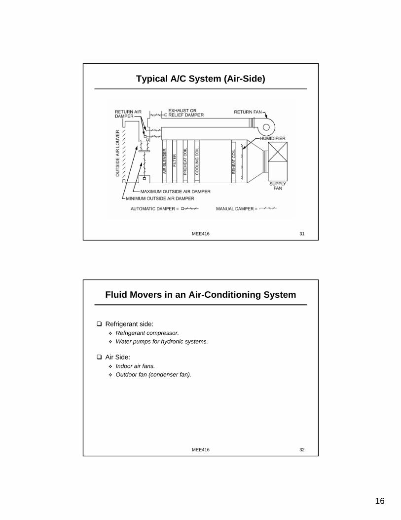
Typical A/C System (Air-Side)
4
MEE416 7
Properties of Moist Air - Psychrometrics
Moist indoor air is a mixture of dry air and water vapor.Indoor air for human comfort typically contains ~1% moisture by mass.
Moist air conditions are determined by properties such as:Dry-bulb temperature (DBT, F).Wet-bulb temperature (WBT, F).Dew point temperature (DPT, F)Relative humidity (RH, %).Humidity Ratio (HR, lb of H2O/lb of dry air).Enthalpy (h, Btu/lb of dry air).Specific volume (v, ft3/lb)
For a given pressure, the thermodynamic properties of humid air can be fully determined by the specification of two independent properties (e.g., DBT and WBT, or DBT and RH).
MEE416 8
Properties of Moist Air - Psychrometrics
Any state property of moist air, S can be expressed as:
in which γ is the mass fraction of water vapor in moist air.But mole fraction of water vapor in moist air is given by:
x = γ/Mw/[(1-γ)/Ma + γ/Mw] = Pw/Pt,
which allows us to determine partial pressure of H2O vapor from HR.
RH = Pw/Pw(sat at DBT)*100%
5
MEE416 9
Psychrometric Chart (ASHRAE)
MEE416 10
Psychrometric Processes
Cool Heat
Humidify
Dehumidify
Cool & Dehumidify
Air Conditioning Systems Cool & Dehumidify Air
6
MEE416 11
Laboratory Groups
Divide into groups of 6-8:
Lab 2: M 09:45 – 12:45 PM 0031 Link HallLab 3: W 12:45 – 03:35 PM (Cancelled)Lab 4: Th 05:30 – 8:30 PM 0031 Link HallLab 5: F 03:45 – 6:30 PM 0031 Link Hall
MEE416 12
Lab Assignments
Draw a schematic of the air circuit of the Hampden Model H-ACD-2 Recirculating Air Conditioning Demonstrator, indicating each of the components in the air circuit.
Conduct the following experiments in the Student Manual of the Hampden H-ACD-2 Recirculating Air Conditioning Demonstrator:
Experiment 1: Air Flow measurementExperiment 2: Wet bulb temperature measurementExperiment 9: Air conditioning process
Write a report to summarize the experimental results and answer the following questions regarding the results of Experiment 9:
Why the cooling capacities were different for the two test conditions (i.e. with vs. without the heater)?What is the amount of sensible heat, latent heat and moisture removed under each test condition (Hint: Figure 8-10 of Reference 1)?
7
MEE416 13
Lab Report Requirements
Each student must submit a lab report that includes the following components (with % of grade points indicated in the parenthesis):
Results and discussions (30%).Conclusions and recommendations (20%).References (5%).
Papers or report referencedAttach a copy of the team presentation
Note: Note: Team presentation and class/lab participations account for Team presentation and class/lab participations account for 20% of final grade.20% of final grade.
MEE416 14
B. Experiment 2
AirAir--Conditioning: Refrigeration Cycle ExperimentConditioning: Refrigeration Cycle Experiment0031 Link Hall0031 Link Hall
8
MEE416 15
Outline of Experiment 2 Lecture
Air-Conditioning: Why do we need Refrigeration?Basic Components of a Vapor Compression System.Properties of Refrigerants.Objectives of this Experiment.Lab Assignments.
MEE416 16
Typical A/C System (Air-Side)
9
MEE416 17
Basic Components of an A/C System
Heat exchanger for cooling/dehumidifying, or for heating the air.Water or refrigerant on one side and air on the other.
Air movers (fans and blowers) to move the air within the system and into and from the conditioned space.Humidifier (steam or evaporative) for adding moisture to the air.Air ducts to carry the circulated air within the A/C system and into and from the conditioned space.Air control dampers to control air flow paths and quantity.Sensors and controls (e.g., thermostats).Air filters to remove gaseous and particulate contaminants.
Why do we need a water or a refrigerant cooled heat exchanger?Why do we need a water or a refrigerant cooled heat exchanger?
MEE416 18
A/C System Psychrometric Processes
Room Condition Line
Coil temperature must be cooler than room dew point (DP) to dehumidify the air Coil Inlet
Room Return Air
Outdoor Air
Room DP
Coil Exit
10
MEE416 19
Refrigeration Cycle Experiment
How the cooling capacity is provided – Principles of Refrigeration.
What are the basic properties of a refrigerant.
How to represent the thermodynamic conditions of the refrigerant, and analyze/visualize a refrigeration cycle using a pressure enthalpy (P-h) chart.
How to measure and determine the operating status and performance of a refrigeration system.
MEE416 20
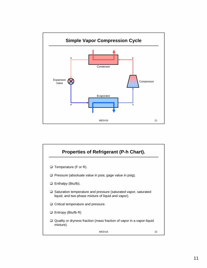
Basic Components of a Refrigeration System
A refrigerant as a working medium (e.g., tetra-fluoroethane – R134a).
An evaporator in which the refrigerant changes phase from liquid to vapor, thus absorbing heat from the air and producing a refrigeration efect (cooling for air-conditioning).
A compressor for pumping the refrigerant vapor to a pressure whose saturation temperature is higher than the the outdoor temperature.
A condenser in which superheated refrigerant vapor is condensed to a subcooled liquid.
A liquid receiver for collecting the condensed liquid refrigerant.
An expansion valve for throttling the refigerant liwuid from the condenser pressure to the evaporator pressure; also controls refrigerant flow.
11
MEE416 21
1
3 2
4
Simple Vapor Compression Cycle
Compressor
Ecaporator
ExpansionValve
Condenser
MEE416 22
Properties of Refrigerant (P-h Chart).
Temperature (F or R).
Pressure (absoluate value in psia; gage value in psig).
Enthalpy (Btu/lb).
Saturation temperature and pressure (saturated vapor, saturated liquid, and two-phase mixture of liquid and vapor).
Critical temperature and pressure.
Entropy (Btu/lb R)
Quality or dryness fraction (mass fraction of vapor in a vapor-liquid mixture).
12
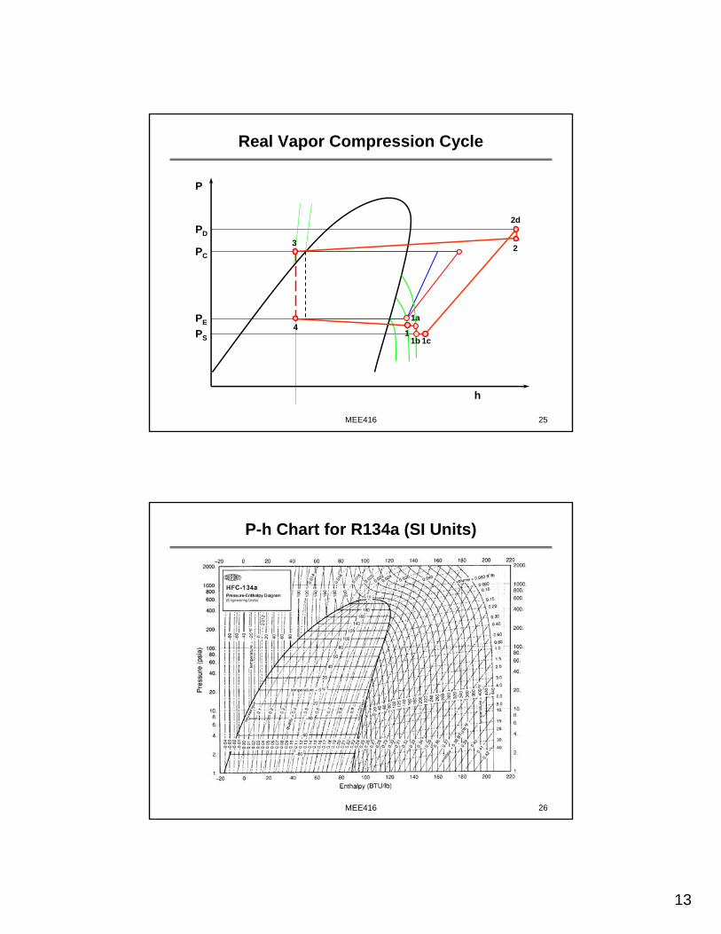
MEE416 23
Refrigeration Cycle
The P-h chart (Mollier chart) for the refrigerant (R134a here) is a powerful tool for analyzing the refrigeration cycle process:
Expansion (e.g., from subcooled point A: 100 F & 153.7 psia condenser pressure to point B at 49.7 psia evaporator pressure).
Evaporation (e.g., from point B at 49.7 psia evaporator pressure to saturated vapor point C, and on to superheated vapor point D at 50 F).
Compression (e.g., from point D at 50 F tp Point E).
Condensation (e.g., from point E at 160 F and 153.7 psia to point G at 153.7 psia saturated liquid, then to subcooled liquid at point A to complete the cycle).
MEE416 24
Single-Stage Vapor Compression Cycle
ΔhWΔhE h
P
PE
PC
ΔTSC
ΔhWo
ΔTSH
A
DC
E
B
13
MEE416 25
h
P
PE
PC
PS
PD
11b
1a
2d
1c
3 2
4
Real Vapor Compression Cycle
MEE416 26
P-h Chart for R134a (SI Units)
14
MEE416 27
Lab Assignments
Conduct the following experiments in the Student Manual of the Hampden Model H-ACD-2 Recirculating Air Conditioning Demonstrator:
Experiment 5: Humidity and Dew Point.Experiment 6: The Refrigeration Cycle.Experiment 7: Effect of Humidity on refrigeration.
Write a report to summarize the experimental results and discussthe findings from Experiment 7 above.
Refrence: Student Manual of the Hampden Model H-ACD-2 Recirculating Air-Conditioning Demonstrator: Chapter 1, 2, 3; and Experiments 5, 6 & 7.
MEE416 28
Lab Report Requirements
Each student must submit a lab report that includes the following components (with % of grade points indicated in the parenthesis):
Results and discussions (30%).Conclusions and recommendations (20%).References (5%).
Papers or report referencedAttach a copy of the team presentation
Note: Note: Team presentation and class/lab participations account for Team presentation and class/lab participations account for 20% of final grade.20% of final grade.
15
MEE416 29
C. Experiment 3
AirAir--Conditioning: Fan ExperimentConditioning: Fan Experiment0025 Link Hall0025 Link Hall
MEE416 30
Outline of Experiment 3 Lecture
Role of fans in an Air-Conditioning SystemIntroduction to TurbomachinesFan Performance Characteristics.Fan Scaling Laws.Objectives of this Experiment.Lab Assignment.Report Format.
16
MEE416 31
Typical A/C System (Air-Side)
MEE416 32
Fluid Movers in an Air-Conditioning System
Refrigerant side:Refrigerant compressor.Water pumps for hydronic systems.
Air Side:Indoor air fans.Outdoor fan (condenser fan).
17
MEE416 33
Role of fans in HVAC Systems
To deliver air flow to the conditioned space.
To overcome air-flow resistance (pressure drop) in the air paths (in ducts, across dampers and through heat exchanger surfaces).
To enhance heat transfer through the outdoor section (condenser in an air-conditiong system).
Hydraulic Pumps & Turbines; Gas Compressors; Steam and Gas Turbines; Hydraulic Couplings; Windmills; Propellers and Fans:
Radial, Mixed-flow, Axial; Impulse & Reaction; Single and Multi-stage.Air conditioning system fansCentrifugal refrigerant compressors for large chillers.
18
MEE416 35
Classification of Fluid Machines
Centripetal, Mixed, Axial Flow; Impulse and Reaction Turbines,
Windmills …
Hydraulic Motors; Piston, Vane, Screw Expanders
…
Motors; Turbines; Expanders
Centrifugal, Mixed, Axial Flow; Ship Screws;
Aircraft Propellers …
Piston, Vane, Scroll, Screw, Roots, Rolling
Piston …
Pumps; Compressors; Propulsion Devices
Rotodynamic(Turbomachines)
Positive Displacement Machines
MEE416 36
Axial and Radial Flow Fans
AxialAxialUsually used in the outdoor section
of an air-conditiong system
RadialRadialUsually used in the indoor section
of an air-conditiong system
Backward SweptBlades
19
MEE416 37
Axial Flow Turbomachines
Titanic
MEE416 38
Radial & Mixed-Flow Turbomachines
20
MEE416 39
Fan Performance Characteristics
Fan performance is characterized by the following parameters:Pressure rise (head) expressed in inch water, Pa,…
1 inch W.G. = 5.204 lbf/ft2
Volumetric flow rate expressed in cfm, m3/s…Fan efficiency (fluid power divided by shaft input power).Fan rotational speed (RPM, radians/s…).Fan shaft horsepower (shaft power input).
Fan performance is presented as either tables or charts showing:Pressure rise (ΔP), efficiency (η) and power (W) as a function of volume flow rate (Q) for different speeds (RPM).
MEE416 40
Fan Performance Curves
Increasing RPMIncreasing RPM
21
MEE416 41
Fan Power
Fluid power Wf is the useful power imparted to the fluid by the fan:
ΔP could be the static pressure rise, the total pressure rise or the total-to-static pressure rise.
Shaft power Ws is the mechanical (shaft) power input to the fan:The term brake horsepower (BHP) should be used only for power generating machines, like engines and turbines.The correct term for power consuming machines like pumps, fans and compressors is shaft horsepower (SHP).
Efficiency,
Q.PWf Δ=&
s
fWW
=η
MEE416 42
Dimensional Analysis of a Fan
For geometrically similar fans we obtain the following relations, using the Buckingham Pi theorem.
ΔPs = the static pressure rise;Q = the volumetric flow rate;D = characteristic diameter;N = rotational speedρ = densityW = fluid power;Ψs = static head coefficient;Φ = flow coefficient;Re = Reynolds Number;L = power coefficient;η = aerodynamic efficiency. Re),(f
Re),(F
NDRe
DNW
NDQ
DN
P),,N,D,Q(fP
s
2
53
3
22s
s
s
ΦηΦΨ
μρ
ρΛ
Φ
ρ
ΔΨ
μρΔ
=
=
=
=
=
=
=
&
22
MEE416 43
Scaling of Fan Performance Curves
MEE416 44
Dimensionless Representation
3NDQ
=Φ
22DNP
ρ
ΔΨ =
Head (Pressure) Coefficient
Flow Coefficient
23
MEE416 45
Fan Scaling Laws
For geometrically similar machines operating under similar operating conditions, dynamic similarity implies:
Φ1 = Φ2
Ψ1 = Ψ2
η1 = η2
Λ1 = Λ2
These laws are valid if the effects of reynold numbers are negligible, i.e., Re is very high, which it often is.
MEE416 46
Fan Test Tunnel: 0025 Link Hall
The lab set-up has a supply fan upstream of the test fan.
StroboscopeStroboscope
24
MEE416 47
Lab Assignment (1)
Objective:Learn how to map fan performance data.Enhance understanding of fan performance characteristics, dimensional analysis and fan scaling laws.Obtain hands-on experience on fan testing.
Test Facility:Fan test tunnel.Instruments for measuring pressure, flow rate, power and speed (RPM).
Fan performance to be measured:Fan static pressure rize versus flow rate.Shaft power input versus flow rate.
MEE416 48
Lab Assignment (2)
Task 1: Perform fan testing at 1600 RPM and plot results graphically as:ΔP vs. Q and η vs. Q.
Task 2:Using fan scaling laws, predict performance at 1200 and 2000 RPM.
Task 3:Using fan scaling laws, predict the performance of a geometrically similar fan with a diameter that is 50% larger than the tested fan and with 1600 RPM. Plot the data in dimensional form.
25
MEE416 49
Lab Report Requirements
Each student must submit a lab report that includes the following components (with % of grade points indicated in the parenthesis):
Results and discussions (30%).Conclusions and recommendations (20%).References (5%).
Papers or report referencedAttach a copy of the team presentation
Note: Note: Team presentation and class/lab participations account for Team presentation and class/lab participations account for 20% of final grade.20% of final grade.