16
METHOD OF JOINTS CSX Railroad Bridge Great Miami River Dayton, Ohio

METHOD OF JOINTS
CSX Railroad BridgeGreat Miami RiverDayton, Ohio

As previosuly described, trusses are constructed entirely of two-force members. Thus the forces in these members lie along the length of the member and transmit loads axially in tension or compression to or from a frictionless joint
In other words, a joint is a point of concurrency of member forces and can be solved as such. The method of joints is simply an application of concurrent forces. The FBD will be that of the joint, not the member. The illustration below indicates how one indicates a tensile or compressive member when drawing the FBD of a joint
Method of Joints
2
Tensile Member
Compresive Member

The general approach of the method of joints involves selecting a joint of the truss where there is at least one known force and at most two unknown forces. In order to start such an analysis, it may be necessary to solve for support reactions first
Once the first joint is solved, the solutions are transferred to an adjacent joint where they become the known forces for that joint. A second concurrent solution is completed which allows a transfer to a third joint and so on until the truss is completely analyzed
Since the method of joints is nothing but a series of concurrent force problems a major disadvantage of the process is the accuracy of each answer depends on all the previous work. Therefore an error early in the solution creates errors in all of the work that follows. Consequently, it is important to work carefully and check your work at each stage before proceeding to the next step
3
Method of Joints

When solving for member forces in a truss, it is common to neglect weight of the members. This is acceptable for lightweight trusses, but many be necessary for large heavy steel members
The weight of a member can be included by applying half the weight of each member at the joints as shown below
4
A B
C
12
W AB W AC 12
W AB W BC
12
W AC W BC
Method of Joints
However, to include member weight, one must know the size of the member. This is a function of the analysis one is doing. As such, including member weight becomes an iterative process. One must first approximate the weight of the member, determine the resulting forces, size the member, then check to determine if the weight assumed is valid
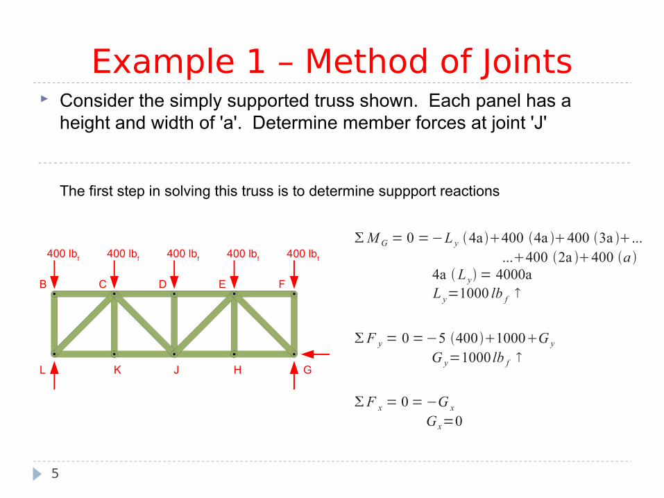
Consider the simply supported truss shown. Each panel has a height and width of 'a'. Determine member forces at joint 'J'
The first step in solving this truss is to determine suppport reactions
5
Example 1 – Method of Joints
400 lbf
400 lbf
400 lbf
400 lbf
400 lbf
B C D E F
GHJKL
M G = 0 =−L y 4a400 4a 400 3a ......400 2a 400 a
4a L y = 4000aL y=1000 lb f
F y = 0 =−5 400 1000G y
G y=1000 lb f
F x = 0 = −G x
Gx=0
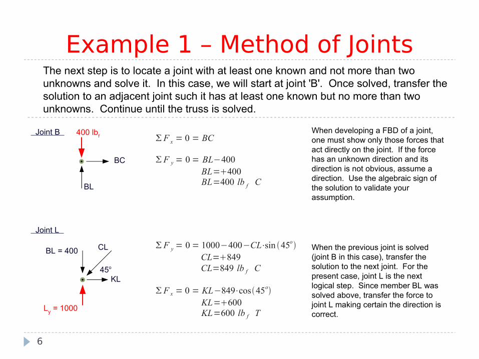
The next step is to locate a joint with at least one known and not more than two unknowns and solve it. In this case, we will start at joint 'B'. Once solved, transfer the solution to an adjacent joint such it has at least one known but no more than two unknowns. Continue until the truss is solved.
6
Example 1 – Method of Joints
F x = 0 = BC
F y = 0 = BL−400BL=400BL=400 lb f C
400 lbf
Joint B
BC
BL
F y = 0 = 1000−400−CL⋅sin 45oCL=849CL=849 lb f C
F x = 0 = KL−849⋅cos45oKL=600KL=600 lb f T
Ly = 1000
BL = 400 CL
KL
Joint L
45o
When developing a FBD of a joint, one must show only those forces that act directly on the joint. If the force has an unknown direction and its direction is not obvious, assume a direction. Use the algebraic sign of the solution to validate your assumption.
When the previous joint is solved (joint B in this case), transfer the solution to the next joint. For the present case, joint L is the next logical step. Since member BL was solved above, transfer the force to joint L making certain the direction is correct.

7
Example 1 – Method of JointsF y = 0 = KC
F x = 0 = KJ−600KJ=600KJ=600 lb f T
KC Joint K
KJKL = 600
From joint L, we have the option of going to either joint C or joint K. An inspection of joint C indicates there are still three unknowns while joint K has two unknowns. Develop the FBD for joint K making sure the directions of known forces are correct.
Member KC deserves discussion. By calculation, this member has a value of zero. This member is referred to as a zero-force member. There are two definitions of a zero-force member: If only two noncollinear members are pinned and there are no loads or reactions at that
pin, then both connected members are zero-force If three members meet at a pin, and two of them are collinear, and there are no loads or
reactions at that pin, then the third member is zero-force Joint K complies with the second definition, thus it becomes obvious by inspection that
member KC is zero-force. If this were recognized immediately, joint C would have only two unknowns and we could have solved that even before solving joint K

8
Example 1 – Method of JointsF y = 0 =−4000849⋅sin 45oCJ⋅sin 45o
=200CJ⋅sin 45oCJ=−283CJ=283 lb f T
F x = 0 = 0CD849⋅cos45o−−283⋅cos 45o=CD800CD=−800CD=800 lb f C
400 lbf
Joint C
CD
KC=0
BC=0
45o
LC=849 CJ
45o
A FBD of joint C is constructed by showing known forces in their proper direction and drawing members CJ and CD with assumed directions. The solution of CJ is negative indicating our assumption of CD in tension is incorrect, it is actually in compression
When the sum of forces expression is written for the x‑direction, it is written as if CJ has a negative x-direction. However, the value substituted for CJ is negative and is substituted as such. This approach prevents mistakes during solution and confusion when the calcuations are reviewed.

9
Example 1 – Method of JointsF x = 0 = 800−DE
DE=800DE=800 lb f C
F y = 0 = JD−400JD=400JD=400 lb f C
F y = 0 = 283⋅sin 45o−400JE⋅sin 45oJE=283JE=283 lb f T
F x = 0 = JH283⋅cos 45o−283⋅cos 45o−600JH=600JH=600 lb f T
JD
DE
Joint D With the solution of joint C, develop the FBD of joint D. Transfer the load in CD to joint D ensuring proper direction. With four orthogonal forces, the direction of JD and DE is rather obvious.
Finally, we have enough information to develop the FBD of joint J. The solution of joint J is shown below.
Joint J
JH
JD = 400
KJ=60045o
CJ=283 JE
45o
400 lbf
CD=800

One can draw two conclusions about the method of joints from the previous example:
This method is quite tedious. It can take a significant amount of time find the solution one wishes. This will be addressed in the next section with the introduction of truss solution using the method of sections Because the solution of a joint is dependent upon a previous solution, it is somewhat prone to error
This last point can be addressed if one uses the method of joints to also solve for reactions then comparing that solution to the reactions as one might find normally. This is illustrated in the next example
10
Method of Joints

Consider the cantilevered truss shown below. One can determine the force in all members without finding reactions first. Simply solve the joint at 'A', followed by 'C', then finish with joint 'B'. However, if one were to go a step further and solve the joint at 'E', all reactions would be found. At this point, one could also find reactions by solving the truss as its own FBD. If you get the same reactions, it is likely the intermediate solutions using joints are valid as well. Let's continue
11
Example 2 – Method of Joints
EC
D
A
B
12 kips
8 kips
4' 4' 4'
4'3'
2'

12
Example 2 – Method of Joints
Joint A
AC
12 kips
AB
34
14
F y = 0 =35AB−
1
17AC
F x = 0 =45AB 4
17AC
solving F x for AB
AB =5
17AC
substituting:
F y =35 5
17AC − 1
17AC
AC=−12.36AC=12.36 kips C
AB=14.99 kips T

13
Example 2 – Method of JointsF y = 0 = BC−8−
1
1712.36
BC =11BC = 11 kips T
F x = 0 =4
1712.36−CE
CE = 11.99 kips C
AC=12.36
Joint C
8 kips
CE14
BC
Joint BBD
BEBC=11
AB=14.99
21
21
34
F y = 0 = −35⋅14.99−11
1
5BE
1
5BD
F x = 0 =−45⋅14.99−
2
5BE
2
5BD
Solving simultaneously:
BD = 29.1 kips TBE = 15.6 kips C
It is important to note the solution for member BD is also the reaction at support D

14
Example 2 – Method of Joints
Joint E
21
BE=15.6
CE=11.99
Ey
Ex
F y = 0 = E y−1
515.6
E y =6.98E y = 6.98 kips
F x = 0 = 11.992
515.6−E x
E x = 25.94 kips
Now that all member forces are known, develop and solve the FBD for pin 'E'. This will provide external reactions at that support
The FBD of joints 'B' and 'E' have provided external support reactions. These were found by using the method of joints. Solving the FBD of the entire structure for support reactions provides a completely independent calculation. Of course, one should arrive at the same solution as when the problem was solved by the mehtod of sections. Let us take look

Not withstanding round-off error, the solutions for all support reactions equal those found using the method of joints. Thus, in all probability, the calculated member forces are correct
15
Example 2 – Method of Joints
EC
D
A
B
12 kips
8 kips
4' 4' 4'
4'3'
2'
112
M E = 0 = 12 kip⋅12 ' 8 kip⋅8 ' − ⋯
⋯ −1
5BD⋅4 ' − 2
5BD⋅6 '
BD=208⋅5
16BD=29.1 kip T
F x = 0 = 29.1⋅2
5−E x
E x=26E x=26 kips
F y = 0 = −12 kip−8 kip29.1⋅1
5E y
E y=7E x=7 kips

As the example problems have shown you, the method of joints is rather tedious. This tedium can be mostly eliminated by using the method of sections. The next section demonstrates this method
16
Method of Joints


