160
GUIDANCE ON THE ASSESSMENT OF THE IMPACT OF OFFSHORE WIND FARMS: Methodology for Assessing the Marine Navigational Safety Risks of Offshore Wind Farms IN ASSOCIATION WITH

GUIDANCE ON THE
ASSESSMENT OF THE IMPACT
OF OFFSHORE WIND FARMS:
Methodology for Assessing the MarineNavigational Safety Risks of Offshore Wind Farms
IN ASSOCIATION WITH

The DTI drives our ambition of‘prosperity for all’ by working tocreate the best environment forbusiness success in the UK. Wehelp people and companies becomemore productive by promotingenterprise, innovation and creativity.
We champion UK business at homeand abroad. We invest heavily inworld-class science and technology.We protect the rights of workingpeople and consumers. And westand up for fair and open markets in the UK, Europe and the world.
GUIDANCE ON THE ASSESSMENT OF
THE IMPACT OF OFFSHORE WIND FARMS:
Methodology for Assessingthe Marine Navigational SafetyRisks of Offshore Wind Farms

Acknowledgements ..................................................................................................................6
Executive Summary .................................................................................................................7
Methodology
1. Introduction...................................................................................................................102. Use and coverage of the methodology......................................................................133. Scope and depth of the developer’s assessment......................................................144. Marine navigational safety goal..................................................................................175. Overview of the methodology ....................................................................................196. Mechanism for assessing tolerability of marine navigational
safety risk ......................................................................................................................237. Standard format of a submission ...............................................................................258. Indicative process followed by Government departments and
agencies in assessing a developer’s submission ......................................................289. Indicative process followed by Government departments in
responding to a developer’s submission ...................................................................3010. Guidance to developers in applying the methodology ............................................32
General Guidance and Suggested Techniques
A.1. Overview and guidance on navigation safety issues, MCA MGN 275 (M) .......................................................................................................34
A.2. Overview of formal safety assessment (FSA)............................................................37A.3. Lessons learned............................................................................................................39B.1. Understanding the base case traffic densities and types.........................................41B.2. Predicting future densities and types of traffic..........................................................43B.3. Describing the marine environment...........................................................................46C.1. Overview of hazard identification ...............................................................................52C.2. Overview of risk assessment.......................................................................................54C.3. Creating a hazard log ...................................................................................................55C.4. Measuring the level of risk ..........................................................................................59
2 Methodology for Assessing the Marine Navigational Safety Risks of Offshore Wind Farms
Contents

Methodology for Assessing the Marine Navigational Safety Risks of Offshore Wind Farms
C.5. Influences on the level of risk .....................................................................................65C.6. The tolerability of residual risks..................................................................................68D.1. Overview of appropriate risk assessment.................................................................71D.2. Selection of techniques that are acceptable to Government ..................................76D.3. Demonstration that the results from the techniques are
acceptable to Government ..........................................................................................81D.4. Navigation risk assessment - area traffic assessment techniques ..........................85D.5. Navigation risk assessment - specific traffic assessment techniques...................104E.1. Creating a risk control log .........................................................................................110E.2. Cost benefit assessment in risk control and mitigation selection .........................113E.3. Assessing the equity of risk controls and mitigations to stakeholders.................115F.1. Tolerability of risk claims supported by a reasoned argument..............................118G.1. Example hazard identification checklist ...................................................................120G.2. Example risk control checklist ...................................................................................123G.3. MCA wind farm application check off list for MGN 275 compliance ....................125H.1. Terms, abbreviations and references .......................................................................129
Appendices Providing Further Information & Guidance
Appendix A: MCA formal safety assessment notes ..........................................................132Appendix B: MCA MGN 275: Proposed UK offshore renewable energy installations (OREI) - Guidance on navigational safety issues .........................................142
3

Figures
Figure 1 Key Features of the Methodology ...................................................................................19
Figure 2 Main Sections of the Submission....................................................................................20
Figure 3 Overview of the Process to Develop Navigation Risk Assessments ............................21
Figure 4 Overview of Formal Safety Assessment .........................................................................37
Figure 5 Lessons Learned Log (Use of Lessons from other Wind Farms...................................39
Figure 6 Lessons Learned Log (Reporting Lessons to other Wind Farms) ................................39
Figure 7 A Method of Statistical Forecasting ...............................................................................45
Figure 8 Overview of Causal Chains .............................................................................................52
Figure 9 Overview of the Human Element ...................................................................................53
Figure 10 Causal chain of events impinging on an offshore wind farm.......................................53
Figure 11 Classic Definition of Risk .................................................................................................54
Figure 12 Overview of Influences on the Level of Risk .................................................................54
Figure 13 Example Hazard Log - Hazard Identification...................................................................56
Figure 14 Example Hazard Log – Risk Assessment ........................................................................56
Figure 15 Example Hazard Log – Confidence Assessment ............................................................57
Figure 16 Example Hazard Log – Risk Control Assessment...........................................................57
Figure 17 Example Hazard Log – Risk Tolerability ..........................................................................57
Figure 18 Example Hazard Log – Closure ........................................................................................58
Figure 19 Example Criticality Matrix - Decade Based.....................................................................59
Figure 20 Example Criticality Matrix - Numerically Ranked...........................................................60
Figure 21 Example Criticality Matrix - Selected Ranking ...............................................................60
Figure 22 Definition of Risk Including Uncertainty .........................................................................63
Figure 23 Example Evidence Matrix .................................................................................................63
Figure 24 Example FN Curve.............................................................................................................64
Figure 25 HSE Framework for the Tolerability of Risk ....................................................................69
Figure 26 Example Format for a Validation Statement...................................................................81
Figure 27 Number of Marine Accidents (1991 / 2004) ....................................................................84
Figure 28 Scenarios Requiring Area Traffic Assessment................................................................87
Figure 29 Area Traffic Assessment – Performance Standards.......................................................93
Figure 30 Tidal Streams and Currents with the Potential to Impose a Navigation
Constraint...........................................................................................................................95
Figure 31 Area Traffic Assessment Illustrative Example - Traffic Review and
Development Flow Chart ..................................................................................................97
Figure 32 Area Traffic Assessment Illustrative Example - Baseline Assessment
and Validation Flow Chart ................................................................................................99
Figure 33 Area Traffic Assessment Illustrative Example - Forecasting using the
Model or other Assessment Technique Flow Chart .....................................................101
Figure 34 Area Traffic Assessment Illustrative Example - Treatment of Limited Visibility ............103
Figure 35 Example of an Electronic Navigational Chart modified with a wind farm.....................106
Figure 36 Initial MCA Guidance on Boundary Clearance Distances from Shipping Routes .........108
Figure 37 Example Risk Control Log - Risk Control Description..................................................111
Figure 38 Example Risk Control Log - Consultation, Approval & Implementation....................111
Figure 39 Example Risk Control Log - Implementation Options .................................................112
Figure 40 Example Risk Control Log - Implementation Plan .......................................................112
Figure 41 Concept of a Claim Supported by a Reasoned Argument ..........................................119
4 Methodology for Assessing the Marine Navigational Safety Risks of Offshore Wind Farms

Methodology for Assessing the Marine Navigational Safety Risks of Offshore Wind Farms
Tables
Table 1 Key Terminology ...............................................................................................................11
Table 2 Contents of a Marine Navigational Safety Risk Assessment Submission...................25
Table 3 Annexes to a Marine Navigational Safety Risk Assessment Submission ...................27
Table 4 Principal Features of MGN 275 relating to Navigational Safety
Risk Assessment................................................................................................................34
Table 5 Some trials reports and other Lessons Learned ...........................................................40
Table 6 Steps in a Stochastic Method of Future Traffic Prediction ...........................................44
Table 7 Potential Accidents resulting from Navigation Activities ..............................................47
Table 8 Navigation Activities affected by an Offshore Wind Farm............................................48
Table 9 Wind Farm Structures that could affect Navigation Activities......................................49
Table 10 Wind Farm Development Phases that could affect Navigation Activities ...................49
Table 11 Other Structures and Features that could affect Navigation Activities........................49
Table 12 Vessel Types involved in Navigation Activities ..............................................................50
Table 13 Conditions affecting Navigation Activities......................................................................51
Table 14 Human Actions related to Navigation Activities ............................................................51
Table 15 IMO Style Frequency Bands (F) .......................................................................................61
Table 16 IMO Style Consequence Band – People (C) ....................................................................61
Table 17 IMO Style Criticality Matrix (CR) ......................................................................................62
Table 18 Example Risk Tolerability Matrix (T)................................................................................62
Table 19 Risk Factors – Example Checklist.....................................................................................65
Table 20 Influences on Causes – Example Checklist .....................................................................66
Table 21 Traffic Levels – Example Checklist ...................................................................................67
Table 22 Circumstances – Example Checklist ................................................................................67
Table 23 Influences on Consequences – Example Checklist ........................................................67
Table 24 A Possible Hierarchy of Assessment and Trials in support of
Navigation Risk Assessment ............................................................................................72
Table 25 Self-Declaration Information ............................................................................................79
Table 26 Example of Technique or Tool Description .....................................................................80
Table 27 Area Traffic Assessment – Critical Parameters...............................................................90
Table 28 Area Traffic Assessment - Limitations of Assessment...................................................91
Table 29 Example of Stakeholder Types.......................................................................................115
Table 30 Example of Organisations Representing Stakeholders ...............................................117
Table 31 Example Hazard Identification Checklist .......................................................................120
Table 32 Example Risk Control Checklist .....................................................................................123
Table 33 MCA Wind Farm Application Check Off List for MGN 275 Compliance ....................125
Table 34 Marine Accident Categories ...........................................................................................129
Table 35 Risk Terms used in this Methodology ...........................................................................130
Table 36 Abbreviations Used in this Methodology .....................................................................130
Table 37 Some References used in this Methodology................................................................131
5

Acknowledgements
The Department of Trade and Industry(DTI) have produced the“Methodology for Assessing theMarine Navigational Safety Risks ofOffshore Wind Farms” document, inassociation with the Department forTransport (DFT), the Maritime andCoastguard Agency (MCA) and BMTRenewables Limited. The preparationof this guidance has been supportedby a Steering Group, comprising Dr.Caroline Roberts and Angela Wratten(DTI); John Mairs and Jim Spooner(DFT); Joe Collins and Simon Gooder(MCA) and Captain Colin Brown (DTIproject manager). We are indebted tothe input from this Steering Group, inparticular the involvement andcontributions of Captain Colin Brown.Additionally, we would like to thankthe many practitioners whocontributed their helpful commentsand ideas through attendingworkshops, meetings and writtenfeedback throughout the project.
6 Methodology for Assessing the Marine Navigational Safety Risks of Offshore Wind Farms

Methodology for Assessing the Marine Navigational Safety Risks of Offshore Wind Farms
The Department of Trade and Industry(DTI) have produced this document,with the co-operation of theDepartment for Transport (DFT), as aMethodology for Assessing theMarine Navigational Safety Risks ofOffshore Wind farms.
Its purpose is to be used as atemplate by developers in preparingtheir navigation risk assessments, andfor Government Departments to helpin the assessment of these.
The Methodology is centred on riskcontrols and the feedback from riskcontrols into risk assessment. Itrequires a submission that shows thatsufficient risk controls are, or will be,in place for the assessed risk to bejudged as broadly acceptable ortolerable with further controls oractions.
The key features of the Methodologyare that developers are to:
1. Produce a submission that isproportionate to the scale of thedevelopment and the magnitudeof the risks.
2. Produce a submission based onassessing risk by Formal SafetyAssessment (FSA) usingnumerical modelling and / orother techniques and tools ofassessment acceptable togovernment and capable ofproducing results that are alsoacceptable to government.
3. Estimate the “Base Case” level ofrisk based on existing densitiesand types of traffic and theexisting marine environment.
4. Predict the “Future Case” level ofrisk based on the predictedgrowth in future densities andtypes of traffic and reasonablyforeseeable future changes in themarine environment.
7
Executive Summary

5. Produce a “Hazard Log” listing thehazards caused or changed by theintroduction of the wind farm, therisk associated with the hazard,the controls put in place and thetolerability of the residual risk.
6. Define the “ risk controls” thatwill be put in place and create aRisk Control Log.
7. Predict the “Base Case with WindFarm” level of risk based onexisting densities and types oftraffic, the existing marineenvironment and with the windfarm in place.
8. Predict the “Future Case withWind Farm” based on futuretraffic densities and types, thefuture marine environment andwith the wind farm in place.
9. Process this information into asubmission including a claim thatthe risks associated with the windfarm are “Broadly Acceptable” or“Tolerable” on the basis of AsLow As Reasonably Practicable”(ALARP) declarations.
and that Government will base theirdecision on assessing:
1. That the tools and techniquesused in the assessments areacceptable.
2. That the claim in the submissionshows that the wind farm willmeet the sought after level ofmarine navigational safety.
3. That there is sufficientinformation with the submissionto have confidence in the claim.
4. That there is sufficientinformation with the submissionto have confidence thatappropriate risk controls are, orwill be, in place.
8 Methodology for Assessing the Marine Navigational Safety Risks of Offshore Wind Farms

Methodology for Assessing the Marine Navigational Safety Risks of Offshore Wind Farms
1. Introduction...................................................................................................................102. Use and coverage of the methodology......................................................................133. Scope and depth of the developer’s assessment......................................................144. Marine navigational safety goal..................................................................................175. Overview of the methodology ....................................................................................196. Mechanism for assessing tolerability of marine navigational
safety risk ......................................................................................................................237. Standard format of a submission ...............................................................................258. Indicative process followed by Government departments and
agencies in assessing a developer’s submission ......................................................289. Indicative process followed by Government departments in
responding to a developer’s submission ...................................................................3010. Guidance to developers in applying the methodology ............................................32
9
Methodology

10 Methodology for Assessing the Marine Navigational Safety Risks of Offshore Wind Farms
1.1 Development of theMethodology
This project to develop amethodology for assessing themarine navigational safety risks ofoffshore wind farms has been carriedout by the Department of Trade andIndustry (DTI). It has evolved with theclose co-operation of developers,Government, its agencies, and otherstakeholders in conjunction withBritish Maritime Technology (BMT)Renewables Ltd. Extensiveconsultation and research has beencarried out to ensure that themethodology is robust, verified,auditable and accountable in a local,national and international context.
1.2 Risk Control Focused on theMethodology
The Methodology is focused both onrisk controls and in preparing aSubmission that shows that sufficientrisk controls are in place for theAssessed Risk to be judged as:
• Broadly acceptable; or• Tolerable with further controls in
place or actions taken
1.3 Structure of theMethodology
The Methodology comprises threeparts:
• A recommended Methodology(described in the Main Text)
• Guidance (described in the Annexes)• Further general information and
guidance (contained in AppendicesA & B)
Methodology
Developers are invited to carry outMarine Navigational Safety RiskAssessments in accordance with thespirit of the methodology and tosubmit the results in accordance withthe standard format for a submission.
Guidance
Guidance to developers in applyingthe methodology is provided, as areappendices illustrating variousmethods of doing so. Although thespecific aspects of this guidance arenot mandatory, it is stronglyrecommended that developers carryout risk assessments in the spirit ofthe detail indicated.
1. Introduction
Methodology for Assessing the Marine Navigational Safety Risks of Offshore Wind Farms
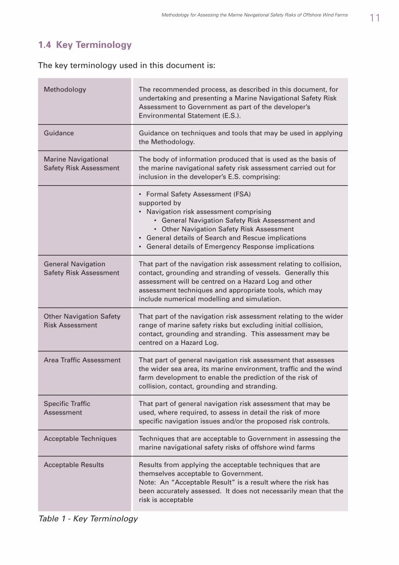
The recommended process, as described in this document, forundertaking and presenting a Marine Navigational Safety RiskAssessment to Government as part of the developer’sEnvironmental Statement (E.S.).
Guidance on techniques and tools that may be used in applyingthe Methodology.
The body of information produced that is used as the basis ofthe marine navigational safety risk assessment carried out forinclusion in the developer’s E.S. comprising:
• Formal Safety Assessment (FSA) supported by• Navigation risk assessment comprising
• General Navigation Safety Risk Assessment and• Other Navigation Safety Risk Assessment
• General details of Search and Rescue implications• General details of Emergency Response implications
That part of the navigation risk assessment relating to collision,contact, grounding and stranding of vessels. Generally thisassessment will be centred on a Hazard Log and otherassessment techniques and appropriate tools, which mayinclude numerical modelling and simulation.
That part of the navigation risk assessment relating to the widerrange of marine safety risks but excluding initial collision,contact, grounding and stranding. This assessment may becentred on a Hazard Log.
That part of general navigation risk assessment that assessesthe wider sea area, its marine environment, traffic and the windfarm development to enable the prediction of the risk ofcollision, contact, grounding and stranding.
That part of general navigation risk assessment that may beused, where required, to assess in detail the risk of morespecific navigation issues and/or the proposed risk controls.
Techniques that are acceptable to Government in assessing themarine navigational safety risks of offshore wind farms
Results from applying the acceptable techniques that arethemselves acceptable to Government.Note: An “Acceptable Result” is a result where the risk hasbeen accurately assessed. It does not necessarily mean that therisk is acceptable
Methodology
Guidance
Marine NavigationalSafety Risk Assessment
General NavigationSafety Risk Assessment
Other Navigation SafetyRisk Assessment
Area Traffic Assessment
Specific TrafficAssessment
Acceptable Techniques
Acceptable Results
1.4 Key Terminology
The key terminology used in this document is:
Table 1 - Key Terminology
11

12 Methodology for Assessing the Marine Navigational Safety Risks of Offshore Wind Farms
1.5 How the Methodology WasDeveloped
Risk Assessment
A number of risk assessmenttechniques may be appropriate foruse in specific circumstances or inrespect of a particular development.
The Maritime and Coastguard Agency(MCA) have had a major role in thedevelopment of Formal SafetyAssessment (FSA) techniques sincethe 1992 Carver Report. An MCAintroduction to Formal SafetyAssessments, together with thetechniques that may be used in them,is contained within Appendix A.
To assist BMT Renewables Ltd indeveloping their input to theMethodology a series of illustrativerisk assessments were undertaken bythem, using their proprietarycomputer based simulation modellingtools and their own preferredprocesses.

Methodology for Assessing the Marine Navigational Safety Risks of Offshore Wind Farms
2.1 Use by Developers
The Methodology has been producedto be used as a template primarily bydevelopers in preparing their marinenavigation safety risk assessments, andhence to identify what type and level ofinformation should be provided by thewind farm developer in an application.
Developers are recommended to carryout marine navigation safety riskassessments in accordance with thespirit of the Methodology and tosubmit the results in accordance withthe standard format for a submission.
It is anticipated that the methodologymay also be used by both developersand Government with reference tooffshore wind farms and other types ofoffshore renewable energy installations(OREI).
2.2 Coverage of theMethodology – Risk Areas
The methodology covers the marinenavigational safety risks for navigationand operations taking place within andaround developments and the need for:
• Formal Safety Assessmentsupported by
• Navigation risk assessment,including: -
• Search and rescue overview• Emergency response overview.
2.3 Coverage of the Methodology– Physical Areas
The key risk areas to be covered by themethodology are:• Risks associated with a development• Cumulative risks associated with the
development and the other wind farmdevelopments in the strategic windfarm area
• In-combination effects on the risk ofthe development with other economicdevelopments over the operational lifeof the wind farm.
2.4 Relationship with theEnvironmental Impact Assessment
The Marine Navigational Safety RiskAssessment (produced by applying thismethodology) forms part of theEnvironmental Impact Assessment, asfollows:• The submitted document is an
Environmental Statement• A required part of the Environmental
Statement is a Marine NavigationalImpact Assessment
• A marine navigational safety riskassessment, produced by applying this methodology, is required as part of the Marine Navigational ImpactAssessment
• The marine navigational safety riskaspects of the navigational impactassessment are largely based on theMaritime and Coastguard Agency’sMarine Guidance Note 275 (M)1.
This guidance note is reproduced in fullin Appendix B of this document.
13
2. Use and Coverage of the Methodology
1 Marine Guidance Note 275(M) “ Proposed UK Offshore Renewable Energy Installations (OREI) – Guidance on Navigational Safety Issues.” Maritime and Coastguard Agency, August 2004. This is available from www.mcga.gov.uk in the “Guidance and Regulations” section.

14 Methodology for Assessing the Marine Navigational Safety Risks of Offshore Wind Farms
3.1 Proportionality
The scope and depth of thedeveloper’s assessment, together withthe tools and techniques necessary tocarry this out, should beproportionate to the:
• Scale of the development• Magnitude of the risks.
3.2 Judging Proportionality
Developers are advised, prior todeveloping a submission to:
• Inform the MCA of their proposalsand seek guidance
• Carry out a preliminary hazardanalysis
• Define an appropriate programmeof work
• Define the tools and techniques tobe used
• Be prepared to change scope,depth, tools and techniquesresulting from assessed risk as thefull assessment progresses.
3.3 MCA Guidance
The MCA will:
• Give guidance if asked• Be prepared, in principle, to accept
a change in scope, depth, tools andtechniques resulting from theassessed risk as the full assessmentprogresses.
3.4 Examples of Proportionality
High Risk or Large Scale Development
A development in an area where thepotential risks are high, or a large-scale development, would probablyrequire a submission based on a:
• Comprehensive Hazard Log• Detailed and quantified Navigation
Risk Assessment• Preliminary search and rescue
assessment or overview, to agreedMCA requirements
• Preliminary emergency responseassessment or overview, to agreedMCA requirements
• Comprehensive Risk control log.
Low Risk of Small Scale Development
A development in an area where thepotential risks are lower, or a smallscale development, might onlyrequire a submission based on a:
3. Scope and Depth of the Developer’sAssessment

Methodology for Assessing the Marine Navigational Safety Risks of Offshore Wind Farms
• Hazard list• Navigation risk assessment based
on qualitative techniques such as“expert judgement”
• Search and rescue overview, toagreed MCA requirements
• Emergency response overview, toagreed MCA requirements
• Risk Control List.
3.5 Preliminary Search andRescue Operations Assessmentor Overview
The scope of a preliminaryassessment or overview should beproportionate to the scale ofdevelopment and the magnitude ofthe risks. Developers should seekguidance from MCA as to the scope tobe followed.
The wind farm itself may present risksto marine safety that generate theneed for search and rescue operationsor may hinder search and rescueoperations not connected to thedevelopment itself.
Therefore, the preliminary assessmentshould firstly consider all thosefeatures of the proposal that couldpresent problems for the emergencyservices.
These considerations will include, butnot be limited to, the detection andpositioning of casualties within andnear to the wind farm by other vessels,Maritime and Coastguard Agency(MCA) Maritime Rescue C-ordinationCentres (MRCC) or Maritime RescueSub Centres (MRSC), and MCA, RoyalAir Force (RAF) or Royal Navy (RN)helicopters. They should also outlinethe details of the proposed turbinecompliance with Annex 4 of MGN 2752,
in respect of an active safetymanagement system (ASMS)addressing individual turbine marking,lighting, rotor control, emergencyrefuge and communications links.These should link to the developer’sown contingency plans in relation toits personnel working on turbines oroperating within and close to the windfarm. Such plans should form part ofthe Environmental Statementsubmission. It is recommended thatany marine safety aspects of these bediscussed and agreed with MCA.
In general, since surface vessels arethe most likely means of rescue fromwithin wind farms, the assessmentshould give details of the RoyalNational Lifeboat Institution (RNLI)stations and their lifeboats near to thesite, and of any appropriate trainingwhich will be given to lifeboat crews.Such training might include themethods and equipment used inboarding turbines and platforms.
Requirements for more detailed
Search and Rescue Operation
Assessments.
Where appropriate, i.e. in areas ofhigh traffic density, where marinesafety hazards of any type are seen tobe significant, or where passengervessel operations are common, DTI, inco-operation with DfT, may require amore detailed Search and RescueResponse Assessment to beundertaken later as a condition of agranted consent. However, where thefrequency, or the consequences, ofsuch incidents gives rise for evengreater concern, a full assessmentmay be required before consent isgranted.
15
2 Ibid

16 Methodology for Assessing the Marine Navigational Safety Risks of Offshore Wind Farms
Such a full assessment may, ifdeemed appropriate by MCA, include:
• Resource planning assessment• Response planning assessment
The MCA will inform developers oftheir specific requirements in thisrespect.
3.6 Preliminary Assessment oroverview of the RequiredEmergency Response to theSpills of Hazardous andPolluting Substances
Developers should become familiarwith the Government’s “NationalContingency Plan for Marine Pollutionfrom Shipping and OffshoreInstallations” (NCP) of which a newdraft was circulated for consultation inJune 2005 and will shortly beadopted.3 Such pollution, whichincludes oil and a variety of hazardoussubstances, may result from incidentsoccurring within or close to offshorewind farms. The NCP takes account ofthe Civil Contingencies Act (CCA) of2004 of which offshore wind farmdevelopers should also be aware.
The preliminary assessment shoulddetermine the likelihood of any suchincidents occurring, such assessmentto be based on the general navigationrisk assessment and the types ofvessel expected to be found in thevicinity. The potential consequencesof such an incident, with respect toseafarers, the environment, and theshore population should beconsidered.
Any circumstance created by the windfarm development, which mayadversely affect counter pollutionoperations undertaken by theappropriate authorities, should bespecified. These circumstancesshould include counter pollutionoperations relating to incidents notcaused by the wind farmdevelopment, but into whose area theresulting pollution may drift.
Requirements for more detailed
Emergency Response Assessments
Depending on the above assessment,DTI, in co-operation with DfT, mayrequire a more detailed emergencyresponse assessment to beundertaken later, as a condition of agranted consent. However, where thefrequency, or the consequences, ofsuch incidents give rise for evengreater concern, a full assessmentmay be required before consent isgranted.
The MCA will inform developers oftheir specific requirements in thisrespect.
3 At the time of publishing this document, greater detail of the National Contingency Plan is obtainable from the MCA’s Counter Pollution Branch via Ms. Gail Robertson, tel. 02380 329482.

Methodology for Assessing the Marine Navigational Safety Risks of Offshore Wind Farms
4.1 Background
The UK Government is committed tothe development of offshore windfarms as part of its 2010 and 2020targets of generating electricity fromrenewable energy sources. Thesewind farms should co-exist safely withother users of the sea with theminimum increase to the baselinelevel of risk during construction,operation and decommissioning.
4.2 National and InternationalNavigation Safety Goals
The UK Government, the EuropeanUnion or international bodies, such asthe International MaritimeOrganisation, have not yet set anyspecific target for navigational safetyin national or international waters.
4.3 Navigational Safety GoalsAround Wind Farms
Similarly, no specific target has yetbeen set for the allowable change tonavigation safety caused by thedevelopment of wind farms.
4.4 Proposed Navigation SafetyGoal
Due to the lack of specified goals it istherefore prudent to consider theoverarching UK principle of reducingrisk to that which is “as low asreasonably practical” and that“relevant good practice risk controlsare in place”.
This overarching principle is based onthe UK Health and Safety Executive(HSE) document “Reducing RisksProtecting People”, which is a guideto the HSE’s decision-makingprocess4. The document is aimed atexplaining the decision-makingprocess of the HSE5 and thereforecontains useful information on risk-based decision-making.
4.5 Implications of the ProposedNavigational Safety Goal
Implications prior to Consent:
The implication of the proposednavigational safety goal is that safetywill have to be managed through thelife of the offshore installation.Through life safety management willinclude:
• Keeping up to date the marinenavigational safety risk assessment
• Updating risk assessments• Updating risk mitigations and
controls (including the provisionof assets)
4. Marine Navigational Safety Goal
17
4 Reducing Risks Protecting People (RRPP or R2P2), ISBN 0 7176 2151 0, available as a download from www.hse.gov.uk/risk/theory/r2p2.htm 5 RRPP page vi

18 Methodology for Assessing the Marine Navigational Safety Risks of Offshore Wind Farms
• Having a safety policy• Having a commitment to install
features designed to comply withMGN 275 Annex 4 requirements.
• Running an active safetymanagement system
• Keeping current a safety andoperations plan
• Having an emergency plan• Maintaining a safety culture• Having a process for “Through Life
Review”.
Implications Post Consent
As much of this will involve work afterthe consent period is granted, at theconsent application stage thedeveloper’s marine navigationalsafety risk assessment must make acommitment to:
• Marine navigation risk assessment• Set in place the risk mitigations
and controls (including theprovision of assets) listed in theapplication
• Undertake any required postconsent search and rescue, andemergency responseassessments.
• Define a safety policy• Follow the BWEA Guidelines for
Health and Safety in the WindEnergy Industry
• Set in place a safety managementsystem
• Install, operate and practice theActive Safety Management System(ASMS) described in Annex 4 ofMGN 275
• Operate in accordance with a safetyand operations plan
• Set up and periodically exercise anemergency plan
• Take positive action to create asafety culture including:
• Board level responsibilities• Measurement and feedback of
the level of compliance• Undertake periodic risk reviews and
implement the findings to keep therisk levels within the goals for theMarine Navigation Safety aspects ofthe wind farm as part of theiroverall approach to safety.

Methodology for Assessing the Marine Navigational Safety Risks of Offshore Wind Farms
5. Overview of the Methodology
5.1 Key Features of theMethodology to achieve theMarine Navigational Safety Goal
The key features of the MarineNavigational Safety Risk AssessmentMethodology are risk assessment(supported by appropriate techniquesand tools), creating a hazard log,defining the risk controls in a RiskControl Log required to achieve a levelof risk that is broadly acceptable (ortolerable with controls or actions), andpreparing a submission that includes aClaim, based on a reasoned argument,for a positive consent decision.
Figure 1 – Key Features of theMethodology
Define a Scope & Depth of thesubmission proportionate to thescale of the development and themagnitude of the risks
Estimate “base case” level of risk
Predict “future case” level of risk
Create a hazard log
Define risk controls and create a riskcontrol log
Predict “base case with wind farm”level of risk
Predict “future case with windfarm” level of risk
Submission
To produce a submission based on
Formal Safety Assessment:
1
2
3
4
5
6
7
8
5.2 Appropriate RiskAssessment Techniques
There is a wide range of riskassessment techniques available andthe selection of the techniques shouldbe:
• Proportionate to the scale of thedevelopment and the magnitude ofthe risk
• Acceptable to Government.
Techniques and tools appropriate toaspects of specific developmentsinclude:
• No action• Expert judgement• Qualitative assessment• Quantitative calculations• Simulations• Trials• Analysis of the real world situation.
Various approaches to riskassessment, using the abovetechniques and tools, can be utilised.These include, amongst others:
• Hazard based risk assessment • Hazard and operability (HAZOP)
studies • Failure modes and effects analysis
(FMEA) • Issues analysis • Risk profile generation.
19

5.4 Main Sections of theSubmission
The main sections of the submissionare:
Figure 2 - Main Sections of theSubmission
5.5 Overview of the Process toDevelop the Navigation RiskAssessments
Figure 3 - Overview of the Process toDevelop Navigation Risk Assessments
Note: The links shown in the righthand column refer to section 7.1, Table 2: “Contents of a MarineNavigational Safety Risk AssessmentSubmission”
20 Methodology for Assessing the Marine Navigational Safety Risks of Offshore Wind Farms
These options are explained in moredetail in Appendix A
The techniques selected will need tobe justified in the Submission bydevelopers.
5.3 Integrity of RiskAssessment
It is important that risk assessmentshould be of high integrity and notjust a quoted risk number. Riskassessment should be used to:
• Prove that the activities (i.e.navigation, search and rescue andemergency response) remainfeasible during construction,operation and decommissioning ofthe development.
• Produce an intelligent comparativevalue of the change in riskassociated with the activity causedby the development
• Assess the sensitivity of the risk tochanges
• Identify, evaluate and decide onappropriate risk controls.
In addition, the discipline of riskassessment is to be used to identifyissues that need to be considered inthe:
• Hazard log• Selection of risk control options.
Summary
Risk claim supported by a reasonedargument and evidence
Description of the marineenvironment
Description of the wind farm andhow it changes the marineenvironment
Analysis of marine traffic
Hazard log
Navigation risk assessment
Search & rescue and emergencyresponse overviews
Risk control log
Cost benefit analysis
Major hazards summary
Statement of limitations
Through life safety management
1
2
3
4
5
6
7
8
9
10
11
12
13

FSA Step 1
FSA Step 2
FSA Step 3
START
Key Feature 1
Key Feature 2
MGN 275Formal SafetyAssessment
A Background
D Modelling & AssessmentB Setting the Scene
D Modelling and Assessment
E Defining the Risk Controls
F, G and H, Developer’s Submission
C Hazard Identification and Risk Assessment
Understanding the“Base Case” levels
of Traffic
Understanding the“Future Case” levels
of Traffic
Understanding the“Base Case with
Wind Farm” levels of Traffic
EmergencyResponse Assets
Qualitative RiskAssessment using
Risk Matrix
Risk MitigationAssets
Tolerability assessedby individual ALARP
Declarations
Risk PreventionAssets
Repeat Assessmentwith Wind Farm
Rule Compliance
Understand the “FutureCase with Wind Farm”
levels of Traffic
Quantitative RiskAssessment
Good Practice RiskControls
Tolerabilityassessed by overallALARP Declaration
Perform Risk Assessment
Perform Risk Assessment
Combine
Hazard Identification
Risk Assessment
Risk Control
Submission
Reasoned Argument and Claim for a Positive ConsentDecision
FSA Step 5
END
Perform Risk Assessment
Perform a Preliminary Hazard Analysis
Define an appropriate Programme of Work
Specify the Tools and Techniques to be used
Seek MCA Approval
Key Feature 3
Key Feature 4
Key Feature 5
Key Feature 6
Key Feature 7
Key Feature 8
Hazard Log
Key Feature 9
Link to Key Features of the Methodology Link to Format of the Submission
Section 2
Section 7d
Section 4
Section 7c
Section 11
Section 10
Section 5d
Predict “Future Case with Wind Farm” Level of Risk
Definition of the “FutureCase with Wind Farm”Marine Environment
Predict “Base Case with Wind Farm” level of Risk
Section 6
Section 4a
Section 7b
Section 7a
Section 3b
Section 3a
Section 5c
Risk ControlOptions
Cost BenefitAnalysis of RiskControl Options
FSA Step 4
Section 5b
Section 5a
Definition of the “Base Case with
Wind Farm” MarineEnvironment
Predict “Future Case” Level of Risk
Definition of the “Future Case”
Marine Environment
Estimate “Base Case” level of Risk
Definition of the “Base Case” Marine
Environment
21
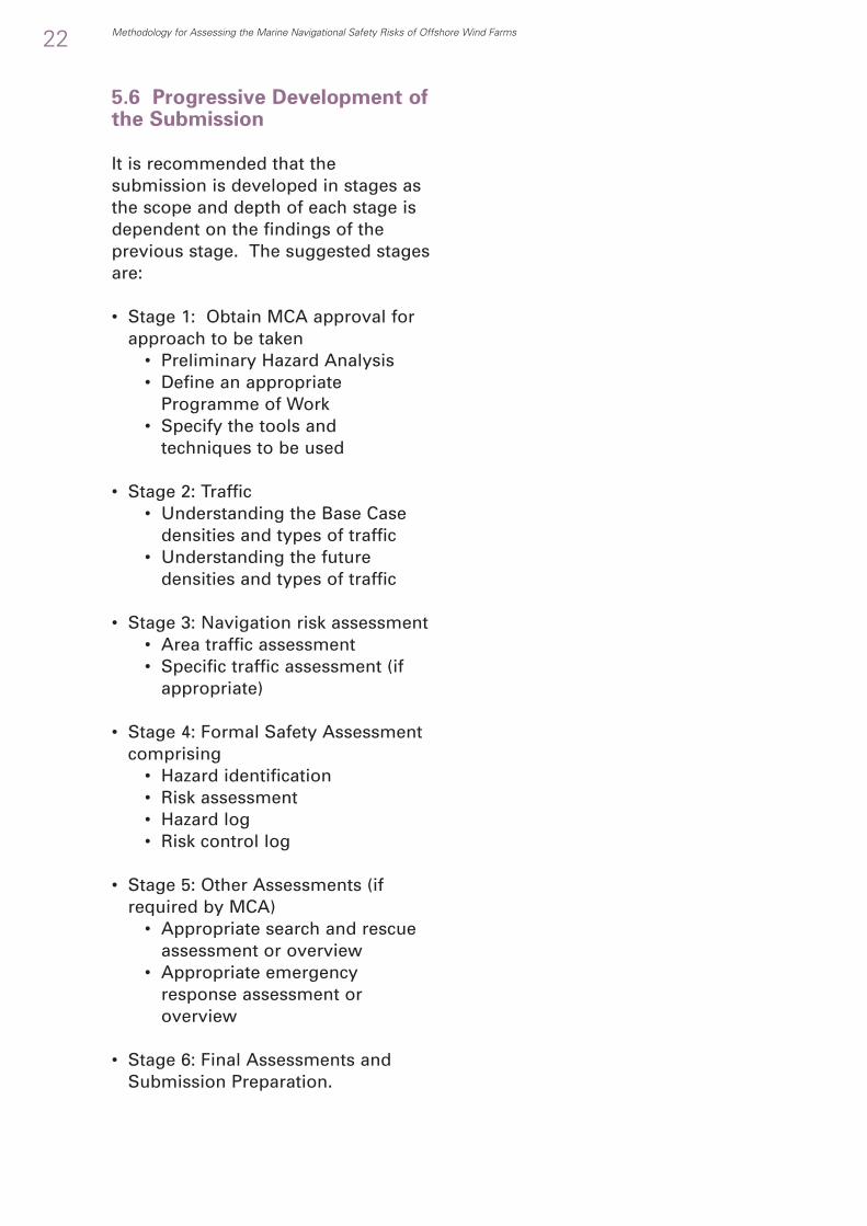
5.6 Progressive Development ofthe Submission
It is recommended that thesubmission is developed in stages asthe scope and depth of each stage isdependent on the findings of theprevious stage. The suggested stagesare:
• Stage 1: Obtain MCA approval forapproach to be taken
• Preliminary Hazard Analysis• Define an appropriate
Programme of Work• Specify the tools and
techniques to be used
• Stage 2: Traffic• Understanding the Base Case
densities and types of traffic• Understanding the future
densities and types of traffic
• Stage 3: Navigation risk assessment • Area traffic assessment• Specific traffic assessment (if
appropriate)
• Stage 4: Formal Safety Assessmentcomprising
• Hazard identification• Risk assessment• Hazard log• Risk control log
• Stage 5: Other Assessments (ifrequired by MCA)
• Appropriate search and rescueassessment or overview
• Appropriate emergencyresponse assessment oroverview
• Stage 6: Final Assessments andSubmission Preparation.
22 Methodology for Assessing the Marine Navigational Safety Risks of Offshore Wind Farms

Methodology for Assessing the Marine Navigational Safety Risks of Offshore Wind Farms
6.1 Tolerability of IndividualRisks
Risk
For each entry in the hazard log therisk shall be assessed against a riskCriticality Matrix6:
• There shall be no unacceptable risks(i.e. criticality 6 or 7)
• All risks in between (i.e. criticality 3 to5) shall be subject to an assessmentof rule compliance and proposed riskcontrols. Further risk control optionsmust be considered to the pointwhere further risk control is grosslydisproportionate (i.e. the ALARPprinciple) and an ALARP justificationand declaration made.
Evidence
For each entry in the hazard log thequality of the evidence shall beassessed against an Evidence Matrix7:
• There shall be no broadlyacceptable risks (i.e. criticality 1 and2) where the evidence supportingthe risk assessment is less than“Expert Opinion – Written” (i.e.category E3).
Risk Controls
For each entry in the hazard log therisk controls shall be listed.
6.2 Tolerability of SocietalConcerns
It is unlikely that reducing all risks inthe hazard log to a level which is “aslow as reasonably possible” (ALARP)will be sufficient to give confidencethat societal concerns are broadlyacceptable. This is because many ofthe risks are interrelated in both causeand consequence and also the affectedstakeholders may have differentperspectives of perceived risks.
Therefore, as a minimum, an overallassessment of societal risk will needto be made as:
• An aggregate of all entries in therisk register; and for
• Major risks such as collision,contact, grounding and stranding
The level of risk can, if appropriate, bedetermined in the form of an FNcurve8 and:
• Base Case• With the current traffic, existing
marine environment without thewind farm
• Is assumed to be tolerable• Base Case with Wind Farm
• With the current traffic, existingmarine environment and withthe wind farm
• The change against the basecase needs to be assessed andjudged against ALARP criteria
23
6. Mechanism for Assessing Tolerability ofMarine Navigational Satety Risk
6 See Annex C4 – Measuring the level of risk7 Annex C4 Fig. 238 See Annex C4 – Measuring the level of risk

24 Methodology for Assessing the Marine Navigational Safety Risks of Offshore Wind Farms
• Future Case• With the future traffic, future
marine environment without thewind farm
• Is assumed to be tolerable• Future Case with Wind Farm
• With the future traffic, futuremarine environment and withthe wind farm
• The change against the futurecase needs to be assessed andjudged against ALARP criteria
These calculations and their resultsshall both be based on techniquesthat are acceptable to Government.
Note: These values of change andtheir tolerability are likely to bedependent on a number of variablesused in the assessment of a windfarm. These will include the size ofthe water space, its bathymetry andhence the sea room available formanoeuvring, and the variations inthe marine operations taking place inthe water space. The larger the spacethe lower the ratio of the wind farm tobase case risk.
Methodology for Assessing the Marine Navigational Safety Risks of Offshore Wind Farms 25
Summary
Risk Claim supported bya Reasoned Argumentand Evidence
Description of theMarine Environment
Description of the WindFarm Development andhow it changes theMarine Environment
Analysis of the MarineTraffic
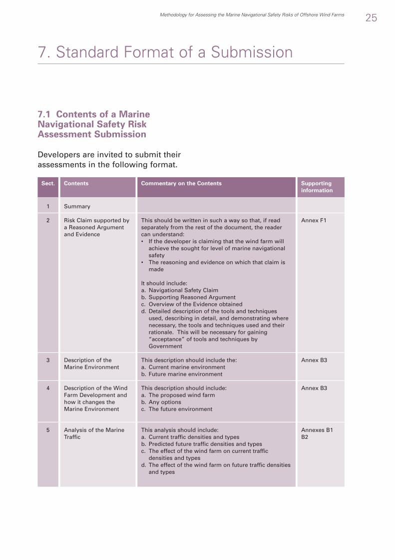
7.1 Contents of a MarineNavigational Safety RiskAssessment Submission
Developers are invited to submit theirassessments in the following format.
7. Standard Format of a Submission
1
2
3
4
5
Annex F1
Annex B3
Annex B3
Annexes B1B2
This should be written in such a way so that, if readseparately from the rest of the document, the readercan understand:• If the developer is claiming that the wind farm will
achieve the sought for level of marine navigationalsafety
• The reasoning and evidence on which that claim ismade
It should include:a. Navigational Safety Claimb. Supporting Reasoned Argumentc. Overview of the Evidence obtainedd. Detailed description of the tools and techniques
used, describing in detail, and demonstrating wherenecessary, the tools and techniques used and theirrationale. This will be necessary for gaining“acceptance” of tools and techniques byGovernment
This description should include the:a. Current marine environmentb. Future marine environment
This description should include:a. The proposed wind farmb. Any optionsc. The future environment
This analysis should include:a. Current traffic densities and typesb. Predicted future traffic densities and typesc. The effect of the wind farm on current traffic
densities and typesd. The effect of the wind farm on future traffic densities
and types
Sect. Contents Commentary on the Contents Supporting
information

26 Methodology for Assessing the Marine Navigational Safety Risks of Offshore Wind Farms
Status of the Hazard Log
Navigation RiskAssessment
Search and RescueOverview andAssessment
Emergency ResponseOverview and Assessment
Status of Risk Control Log
Summary of Cost BenefitAnalyses used in theselection or rejection ofRisk Controls
Major Hazards Summary
Statement of Limitations
Through Life SafetyManagement
6
7
8
9
10
11
12
13
14
Annex C3
Annex D1
Section3.5
Section 3.6
Annex E1
Annex E2
AnnexesG1, G2
E3
This should include:a. Summary of tolerable, ALARP and intolerable risksb. Graphical representation of all risks on a matrix
The risk assessment should include:a. “Base Case” General Navigation Safety Risk Assessmentb. “Future Case” General Navigation Safety Risk Assessmentc. “Base Case with Wind Farm” General navigation risk
assessmentd. “Future Case with Wind Farm” General navigation risk
assessmente. Future Options General navigation risk assessmentf. Other Navigation Safety Risk - a summary of the other
Navigation Safety Risks from the hazard log and the riskcontrols put in place to manage them
Assessment dependent on level agreed with the MCA. In high risk developments this may include, prior to or postconsent:• Resource Planning• Prevention Strategy• Response Plan Assessment
Assessment dependent on level agreed with the MCA.
An overview of the risk controls in the Risk Control Log
Details of any Cost Benefit Assessments completed insupport of Risk Control selection
A summary of the major hazards, how they have beenassessed, how they will be controlled and what trials havebeen undertaken to develop the assessment or controls.Likely “Major Hazards” to be summarised are:• Collision and contact with other vessels and with wind
farm structures• Grounding• Contact with cables and snagging of them• Interference with communications, radar, etc.
An indication of, or a commitment to, the planned throughlife safety management including:• Updating risk assessments• Filling gaps in assessment• Safety Policy• Safety Management System• Safety and Operations Plan• Emergency Plan• Through Life ReviewPlus, details of• Compliance with the MCA’s required Active Safety
Management System as specified in MGN 275 Annex 49
Table 2 - Contents of a MarineNavigational Safety Risk AssessmentSubmission
9 (Ibid)

Methodology for Assessing the Marine Navigational Safety Risks of Offshore Wind Farms 27
Background Information
Setting the Scene
Hazard Log
Results of analysistechniques and toolsused
Risk Control Log
Lessons Learned Log
Quality Checking andVerification of Evidence
Self Declaration againstMGN 275
7.2 Explanatory Annexes
Explanatory annexes may be includedif appropriate to expand on theinformation given in the submission.
Table 3 - Annexes to a MarineNavigational Safety Risk AssessmentSubmission
7.3 Electronic Distribution
The submission and its annexes shallbe capable of electronic circulation(e.g. PDF or similar open standardfiles types from file download sites,over email, etc.).
A
B
C
D
E
F
G
H
This should includea. Base Case densities and types of trafficb. Predicted Future Level of Trafficc. The Marine Environment – development of a Specific Technical and
Operational Analysis
This should include:a. Development of Specific Influences on the Level of Riskb. Hazard log Worksheets or Database
This should include:a. Navigation risk assessmentb. Appropriate search & rescue overview & assessmentc. Appropriate emergency response overview & assessmentd. Selection of Techniques that are acceptable to Governmente. Demonstration that results from the techniques are acceptable to
Government
This should include:a. Risk Control Log Worksheets or Database
This should be a statement on how the assessment has been checked andhow the evidence on which it is based has been verified.
Annex Commentary on the Annex

28 Methodology for Assessing the Marine Navigational Safety Risks of Offshore Wind Farms
8.1 Introduction
This section gives an indication of theprocess that will be followed byGovernment in assessingsubmissions.
8.2 Principle of the Process
The principle behind the processfollowed by government departmentsis that they will seek, the following, ina developer’s submission:
• A claim that if the planned riskcontrols are implemented andmaintained the proposed wind farmwill achieve the sought for level ofmarine navigational safety
• Sufficient information forgovernment departments, theiragencies and other stakeholders tohave confidence in the claim
• A declaration that the risk controlswill be implemented.
8.3 Assessment of InformationSupplied in the Submission
Government Departments will assessif the submission includes informationshowing that:
1) The marine navigational safetyrequirements have been correctlyidentified, based on Formal SafetyAssessment
2) The submission makes a claimagainst the safety requirementsthat:• The rules have been complied
with• As a minimum standard or
relevant good practice, riskcontrols will be put in place
• The risks are: -• Broadly acceptable; or• Tolerable with
modifications; or• Tolerable with additional
controls; or• Tolerable with monitoring
That further risk control is grosslydisproportionate
3) The claim is backed up by areasoned argument
4) The reasoned argument is built onthe use of evidence andappropriate risk assessment toolsand techniques
8. Indicative Process Followed byGovernment Departments and Agencies inAssessing a Developer’s Submission

Methodology for Assessing the Marine Navigational Safety Risks of Offshore Wind Farms
5) The evidence is quality checked
6) Techniques selected areacceptable to Government
7) The results from applying thetechniques are acceptable toGovernment, such as calibrationagainst known data.
8.4 Assessment of theLimitations of the InformationSupplied in the Submission
Government Departments will assessif the submission includes informationshowing that:
1) The nature, assumptions andlimitations of the submission areset out and understood
2) The “absence of evidence of risk”is not taken as “evidence ofabsence of risk”.
29

9.1 Background to theResponse Process
In defining the response process thebroadly stated principles of goodregulation, published by the BetterRegulation Task Force, shortly tobecome the Better RegulationCommission, will be applied. These require:
• The targeting of action: focussingon the most serious risks or wherethe hazards need greater controls
• Consistency: adopting a similarapproach in similar circumstancesto achieve similar ends
• Proportionality: requiring action thatis commensurate to the risks
• Transparency: being open on howdecisions were arrived at and whattheir implications are
• Accountability: making clear, for allto see, who are accountable whenthings go wrong.
9.2 How the Response Processlinks to the Consent ApplicationProcess
The link can be summarised asfollows:
• The submission forms part of thedeveloper’s EnvironmentalStatement based on anEnvironmental Impact Assessment,which is needed to support anapplication for the consents andlicenses necessary for an offshoredevelopment (Section 36 ElectricityAct 1989, Section 34 CoastProtection Act 1949 and section 5Food and Environment ProtectionAct 1985)
• The Developer submits theapplications as appropriate to theElectricity Development ConsentsDirectorate (EDC) of the Departmentof Trade and Industry and to theMarine Consents and EnvironmentUnit (MCEU) (which comprises DTIand the Department forEnvironment, Food and RuralAffairs (DEFRA))
• The DTI, on behalf of the MCEU,circulate it to:
• Other GovernmentDepartments, including theDepartment for Transport andthe Ministry of Defence
30 Methodology for Assessing the Marine Navigational Safety Risks of Offshore Wind Farms
9. Indicative Process Followed byGovernment Departments in Respondingto a Developer’s Submission

Methodology for Assessing the Marine Navigational Safety Risks of Offshore Wind Farms
• A range of organisations suchas, Trinity House, Chamber ofShipping, Royal YachtingAssociation, the port authority(if relevant), NationalFederation of Fishermen’sOrganisations, and the BritishMarine Aggregates ProducersAssociation.
• In addition, DTI will also seekan opinion on the marinenavigational safety risks fromthe Maritime and CoastguardAgency.
The relevant organisations are invitedto advise on the potential marinenavigational safety risk impacts of the:
• Development itself• Development in combination with
other planned or existingdevelopments
• Effect of these on other futuredevelopments
The advice given is likely to fall intothe following categories:• “No objection”• “No objection” with conditions• Holding objection, with a request
for more information or analysis• Objection with reasons
Applicants are informed of this adviceand invited to respond.
9.3 Ultimate Responsibility forConsent
The aim is to involve stakeholders atall stages with the aim of achievingconsensus. However, theDTI/DFT/MCA must makerecommendations to Ministers whereconsensus is not possible, forexample where different stakeholdershold opposite views based on deep-rooted beliefs.
31

32 Methodology for Assessing the Marine Navigational Safety Risks of Offshore Wind Farms
The guidance is given in the followingAnnexes:
ANNEX A Background Information
A1 Overview and guidance onnavigational safety issues, MCAMGN 275 (M)10
A2 Overview of Formal SafetyAssessment
A3 Lessons Learned
ANNEX B Setting the Scene
B1 Understanding the base casetraffic densities and types
B2 Predicting future densities andtypes of traffic
B3 Describing the marine environment
ANNEX C Hazard Identification and
Risk Assessment
C1 Overview of hazard identificationC2 Overview of risk assessmentC3 Guidance on creating a hazard logC4 Measuring the level of riskC5 The Influences on the level of riskC6 The tolerability of residual risks
ANNEX D Appropriate Assessment
Techniques & Tools
D1 Overview of modelling and otherappropriate assessment techniques
D2 The selection of techniques thatare acceptable to Government
D3 Guidance on demonstrating thatthe results from the techniquesare acceptable to Government
D4 Navigation risk assessment - areatraffic assessment techniques
D5 Navigation risk assessment -specific traffic assessmenttechniques
ANNEX E Deciding on the Risk
Controls
E1 Guidance on creating a riskcontrol log
E2 Guidance on cost benefitassessment in risk control andmitigation selection
E3 Guidance on assessing the equityof risk controls and mitigations to stakeholders
ANNEX F Developer’s Submission
F1 Guidance on tolerability of riskclaims supported by reasoned arguments
ANNEX G Example Checklists
G1 Example hazard identificationchecklist
G2 Example risk control checklistG3 Example MCA wind farm
application check off list for MGN275 compliance
ANNEX H
H1 Terms, abbreviations andreferences
Appendices Providing Further
Information or Guidance
Appendix A: MCA Formal SafetyAssessment notesAppendix B: MCA Marine GuidanceNote (MGN) 275 (M)
10. Guidance to Developers in Applyingthe Methodology
10 (Ibid)

Methodology for Assessing the Marine Navigational Safety Risks of Offshore Wind Farms
A.1. Overview and guidance on navigation safety issues, MCA MGN 275 (M) .......................................................................................................34
A.2. Overview of formal safety assessment (FSA)............................................................37A.3. Lessons learned............................................................................................................39B.1. Understanding the base case traffic densities and types.........................................41B.2. Predicting future densities and types of traffic..........................................................43B.3. Describing the marine environment...........................................................................46C.1. Overview of hazard identification ...............................................................................52C.2. Overview of risk assessment.......................................................................................54C.3. Creating a hazard log ...................................................................................................55C.4. Measuring the level of risk ..........................................................................................59C.5. Influences on the level of risk .....................................................................................65C.6. The tolerability of residual risks..................................................................................68D.1. Overview of appropriate risk assessment.................................................................71D.2. Selection of techniques that are acceptable to Government ..................................76D.3. Demonstration that the results from the techniques are
acceptable to Government ..........................................................................................81D.4. Navigation risk assessment - area traffic assessment techniques ..........................85D.5. Navigation risk assessment - specific traffic assessment techniques...................104E.1. Creating a risk control log .........................................................................................110E.2. Cost benefit assessment in risk control and mitigation selection .........................113E.3. Assessing the equity of risk controls and mitigations to stakeholders.................115F.1. Tolerability of risk claims supported by a reasoned argument..............................118G.1. Example hazard identification checklist ...................................................................120G.2. Example risk control checklist ...................................................................................123G.3. MCA wind farm application check off list for MGN 275 compliance ....................125H.1. Terms, abbreviations and references .......................................................................129
General Guidance and Suggested Techniques
33

Developers will be expected to basetheir submissions on addressing thenavigation issues arising from MarineGuidance Note 275 (M) “Proposed UKOffshore Renewable EnergyInstallations (OREI) – Guidance onNavigational Safety Issues.”11
MGN 275 (M) is reproduced in full inAppendix B.
Note that the Maritime andCoastguard Agency may amend ormodify the contents of MGN 275 inaccordance with continuing offshorewind farm experience.
A.1.1 The Principal Features ofMGN 275 relating to MarineNavigational Safety riskassessment are listed below:
34 Methodology for Assessing the Marine Navigational Safety Risks of Offshore Wind Farms
A1 Overview and Guidance NavigationalSafety Issues, MCA MGN 275 (M)
Evaluation of Navigation
Evaluate all navigational possibilities which could be reasonablyforeseeable, by which the siting, construction, establishment anddecommissioning of an OREI could cause or contribute to an obstruction of,or danger to, navigation or marine emergency services.
Assessment of Navigation
Potential navigational or communications difficulties caused to anymariners or emergency services using the site area and its environs shouldbe assessed.Difficulties that could contribute to a marine casualty leading to injury,death or loss of property, either at sea of amongst the population ashoreshould be highlighted.Difficulties, which could affect the emergency services, should be highlighted.
Assessment of Consequences
Assessment of the consequences of ships deviating from normal routes toavoid proposed sites.Assessment of the consequences of recreational craft entering shippingroutes to avoid proposed sites.
Contingency Arrangements
Contingency arrangements to deal with marine casualties in, or adjacent to,sites should be planned and practiced.Contingency arrangements to deal with environmental pollution in, oradjacent to, sites should be planned and practiced.
Site Position, Structures and Safety Zones
Traffic SurveyUp to date traffic survey leading to researched opinion using computersimulation techniques with respect to the displacement of traffic and, inparticular, the creation of 'choke points' in areas of high traffic density
Main Text
Para 2.2.
Main Text
Para 2.3.
Para 2.3.
Para 2.3.
Main Text
Para 2.4.
Para 2.4.
Main Text
Para 3.4.
Para 3.4.
Annex 1
Annex 1 Para 1.
MGN 275 Feature
11 (Ibid)

Methodology for Assessing the Marine Navigational Safety Risks of Offshore Wind Farms 35
StructuresDetermination if structures could pose any difficulty to navigationDetermination if structures can cause problems for emergency rescueservicesDetermine how structures will be controlled in an emergencyAccess to and Navigation WithinAssessment whether navigation within the site would be safeAssessment whether navigation in and / or near the site should beprohibited or avoided.Assessment of exclusion from the site
Navigation, Collision Avoidance and Communications
The effect of tides and tidal streamsThe effect of weatherThe effect on visual navigation and collision avoidanceThe effect on communications, radar and positioning systemsThe proposal for marine navigational marking
Safety and mitigation measures during construction, operation and
decommissioning
Safety and mitigation measures during construction, operation anddecommissioning
Standards and Procedures for Shutdown
Design RequirementsEmergency rotor shut-down in the event of events such as search andrescue, counter pollution or salvage operationOperational RequirementsControl room functionalityOperational ProceduresControl room operation
Annex 1 Para 2.
Annex 1 Para 3.
MGN 275 (M)Annex 1 Para 3.MGN 275 (M) Annex 1 Para 3.
Annex 2
Annex 2 Para 1.Annex 2 Para 2.Annex 2 Para 3.Annex 2 Para 4.Annex 2 Para 5.
Annex 3
Annex 3 Para 1
Annex 4
Annex 4 Section 1
Annex 4 Section 2
Annex 4 Section 3
A.1.2 The Merchant Shipping(Distress Signals and Preventionof Collision) Regulations
MGN 275 requires that assessment ofnavigation risk include theimplications of the InternationalMaritime Organisation’s “InternationalRegulations for Preventing Collisionsat Sea 1972 as amended to date”. Inthe UK these are defined in MerchantShipping Notice 1781 (M + F)12. Theseare sometimes referred to simply asthe “Collision Regulations” or, lessformally, as the “COLREGS”. The assessment tools and techniquesused in the navigational riskassessment must be such that all of
the regulations are applied to thevessel types and operations that makeup the traffic in the sea area underconsideration. Assessments usingnumerical modelling and simulationtools that are not able to meet thisrequirement will need to besupplemented by other techniques.
The rules are listed below. Of thesethe assessment should particularlyaddress Rules 1 to 19 which will notonly affect the probability of collisionand contact between vessels and withwind farm structures, but may alsoinfluence that of grounding when inrestricted water depths. Additionallyany potential interference by the
Table 4 - Principal Features of MGN275 relating to Navigational SafetyRisk Assessment
12 Merchant Shipping Notice 1781 (M + F) “The Merchant Shipping (Distress Signals and Prevention of Collisions Regulations) 1996” The Maritime andCoastguard Agency, May 2004. This is available from the MCA website: www.mcga.gov.uk in the “Guidance and Regulations” section.
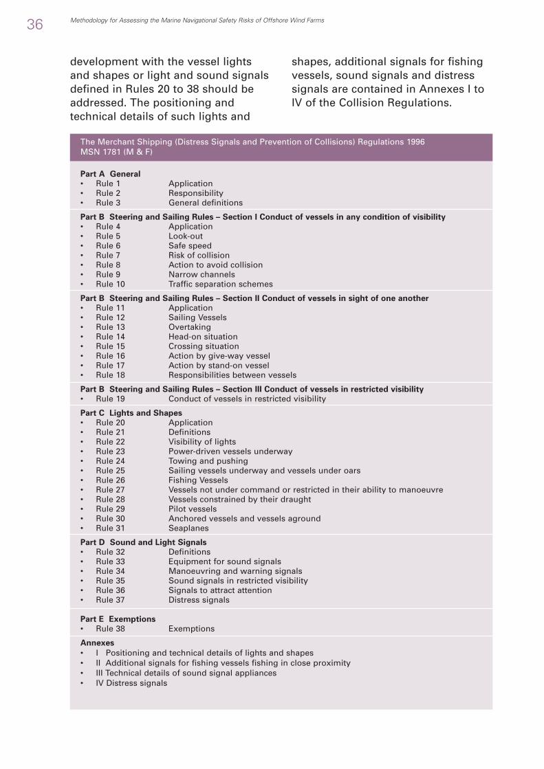
development with the vessel lightsand shapes or light and sound signalsdefined in Rules 20 to 38 should beaddressed. The positioning andtechnical details of such lights and
shapes, additional signals for fishingvessels, sound signals and distresssignals are contained in Annexes I toIV of the Collision Regulations.
36 Methodology for Assessing the Marine Navigational Safety Risks of Offshore Wind Farms
Part A General
• Rule 1 Application• Rule 2 Responsibility• Rule 3 General definitions
Part B Steering and Sailing Rules – Section I Conduct of vessels in any condition of visibility
• Rule 4 Application• Rule 5 Look-out• Rule 6 Safe speed• Rule 7 Risk of collision• Rule 8 Action to avoid collision• Rule 9 Narrow channels• Rule 10 Traffic separation schemes
Part B Steering and Sailing Rules – Section II Conduct of vessels in sight of one another
• Rule 11 Application• Rule 12 Sailing Vessels• Rule 13 Overtaking• Rule 14 Head-on situation• Rule 15 Crossing situation• Rule 16 Action by give-way vessel• Rule 17 Action by stand-on vessel• Rule 18 Responsibilities between vessels
Part B Steering and Sailing Rules – Section III Conduct of vessels in restricted visibility
• Rule 19 Conduct of vessels in restricted visibility
Part C Lights and Shapes
• Rule 20 Application• Rule 21 Definitions• Rule 22 Visibility of lights• Rule 23 Power-driven vessels underway• Rule 24 Towing and pushing• Rule 25 Sailing vessels underway and vessels under oars• Rule 26 Fishing Vessels• Rule 27 Vessels not under command or restricted in their ability to manoeuvre• Rule 28 Vessels constrained by their draught• Rule 29 Pilot vessels• Rule 30 Anchored vessels and vessels aground• Rule 31 Seaplanes
Part D Sound and Light Signals
• Rule 32 Definitions• Rule 33 Equipment for sound signals• Rule 34 Manoeuvring and warning signals• Rule 35 Sound signals in restricted visibility• Rule 36 Signals to attract attention• Rule 37 Distress signals
Part E Exemptions
• Rule 38 Exemptions
Annexes
• I Positioning and technical details of lights and shapes• II Additional signals for fishing vessels fishing in close proximity• III Technical details of sound signal appliances• IV Distress signals
The Merchant Shipping (Distress Signals and Prevention of Collisions) Regulations 1996 MSN 1781 (M & F)
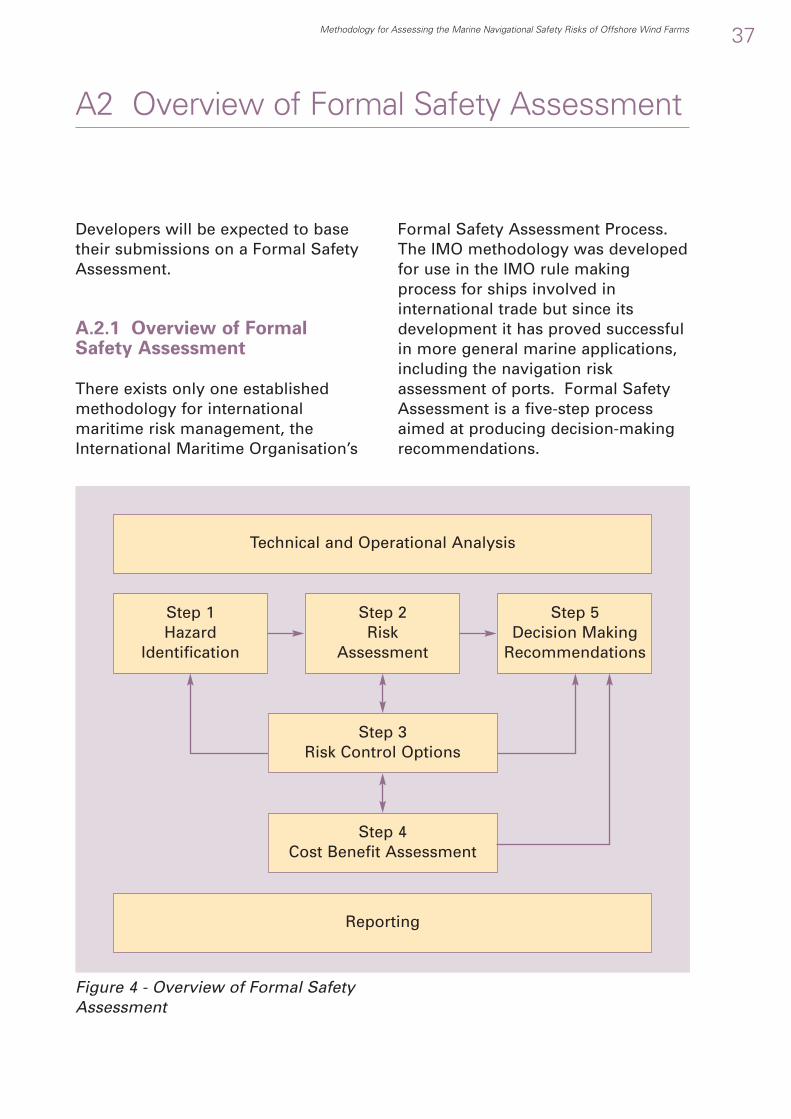
Developers will be expected to basetheir submissions on a Formal SafetyAssessment.
A.2.1 Overview of FormalSafety Assessment
There exists only one establishedmethodology for internationalmaritime risk management, theInternational Maritime Organisation’s
Formal Safety Assessment Process.The IMO methodology was developedfor use in the IMO rule makingprocess for ships involved ininternational trade but since itsdevelopment it has proved successfulin more general marine applications,including the navigation riskassessment of ports. Formal SafetyAssessment is a five-step processaimed at producing decision-makingrecommendations.
Methodology for Assessing the Marine Navigational Safety Risks of Offshore Wind Farms 37
A2 Overview of Formal Safety Assessment
Technical and Operational Analysis
Step 1Hazard
Identification
Step 2Risk
Assessment
Step 4Cost Benefit Assessment
Step 5 Decision Making
Recommendations
Reporting
Figure 4 - Overview of Formal SafetyAssessment
Step 3Risk Control Options

In addition, it introduces a frameworkfor:
• The types of marine accident (e.g.contact, collision, etc)
• The ranges of causes (e.g. humanerror, hardware failure and externalevents)
• The safety, environmental, propertyand business consequences of risks
• Assessing the tolerability of risk tothe stakeholders
• Assessing the equity of risk controlto the stakeholders.
A key aspect of Formal SafetyAssessment is that it stresses that theselection of risks needing controlshould be based on:
• High Risks• Consider frequency of
occurrence together withseverity of outcome
• High Probability Events• Consider high probability events
irrespective of the severity ofthe outcome
• High Severity Outcomes• Consider high severity
outcomes irrespective of theprobability of the event
• Low Confidence• Consider risks where there is
uncertainty in the riskassessment, the probability orthe outcome.
The Maritime and CoastguardAgency’s Risk, Analysis andPrevention Branch publishes guidanceto its approved FSA methodologyoptions on the MCA website:http://www.mcga.gov.uk/.
Relevant sections from this site areincluded in Appendix A of thisdocument.
The website also gives details of MCAcontacts within the Branch.
38 Methodology for Assessing the Marine Navigational Safety Risks of Offshore Wind Farms

Ref ProblemSource of
InformationRoot
Cause(s)LessonsLearned
How the Lesson Learned has been implementedWind Farm XXXX
In any industry, and especially in newindustries, there is considerablebenefit in the sharing of LessonsLearned. This methodologyencourages the use of more formalways of:
• Using the Lessons Learned fromother wind farms
• Reporting Lessons Learned to otherwind farms.
A.3.1 Lessons Learned Log
The suggested method for this is tomaintain and circulate a LessonsLearned Log.
Methodology for Assessing the Marine Navigational Safety Risks of Offshore Wind Farms 39
A3 Guidance on Lessons Learned
Ref ProblemSource of
InformationRoot
Cause(s)LessonsLearned
How the Lesson Learned has been implemented
Wind Farm XXXX
Potential Applicabilityother Wind Farm
Figure 5 - Lessons Learned Log (Useof Lessons from other Wind Farms) -Example Spreadsheet Format
Figure 6 - Lessons Learned Log(Reporting Lessons to other WindFarms) - Example Spreadsheet Format
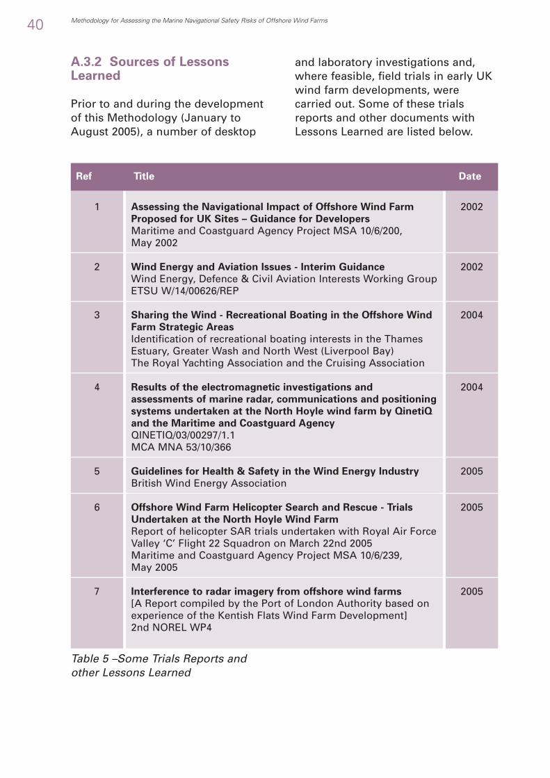
A.3.2 Sources of LessonsLearned
Prior to and during the developmentof this Methodology (January toAugust 2005), a number of desktop
and laboratory investigations and,where feasible, field trials in early UKwind farm developments, werecarried out. Some of these trialsreports and other documents withLessons Learned are listed below.
40 Methodology for Assessing the Marine Navigational Safety Risks of Offshore Wind Farms
Assessing the Navigational Impact of Offshore Wind Farm
Proposed for UK Sites – Guidance for Developers
Maritime and Coastguard Agency Project MSA 10/6/200, May 2002
Wind Energy and Aviation Issues - Interim Guidance
Wind Energy, Defence & Civil Aviation Interests Working GroupETSU W/14/00626/REP
Sharing the Wind - Recreational Boating in the Offshore Wind
Farm Strategic Areas
Identification of recreational boating interests in the ThamesEstuary, Greater Wash and North West (Liverpool Bay)The Royal Yachting Association and the Cruising Association
Results of the electromagnetic investigations and
assessments of marine radar, communications and positioning
systems undertaken at the North Hoyle wind farm by QinetiQ
and the Maritime and Coastguard Agency
QINETIQ/03/00297/1.1MCA MNA 53/10/366
Guidelines for Health & Safety in the Wind Energy Industry
British Wind Energy Association
Offshore Wind Farm Helicopter Search and Rescue - Trials
Undertaken at the North Hoyle Wind Farm
Report of helicopter SAR trials undertaken with Royal Air ForceValley ‘C’ Flight 22 Squadron on March 22nd 2005 Maritime and Coastguard Agency Project MSA 10/6/239, May 2005
Interference to radar imagery from offshore wind farms
[A Report compiled by the Port of London Authority based onexperience of the Kentish Flats Wind Farm Development]2nd NOREL WP4
1
2
3
4
5
6
7
2002
2002
2004
2004
2005
2005
2005
Ref Title Date
Table 5 –Some Trials Reports andother Lessons Learned

The risk assessment needs to be basedon a sound knowledge of the trafficdensities and types. This is one of thekey inputs to assessing proportionality.
Survey Area
The boundary of the survey areashould be constituted at a position sothat further extension of the boundarywould not appreciably impact theresults of the assessment, i.e. boundaryeffects are minimised. A generalguideline could be applied that the areaof direct interest adjacent to the windfarm or wind farm groups should liewithin the centre 1/4 to 1/3 of thesurvey area. However, it is theresponsibility of the analyst todemonstrate that the survey area isappropriate.
B.1.1 Traffic Data Requirements
Marine navigation safety issues withinand close to offshore wind farms existin many situations, and particularlywhere there is a combination of hightraffic levels, different vessel operationsand constrained water spaces. Theseaspects are inter-related with respect tooffshore wind farms. The risk is alsodependent upon the type, size andnature of the vessels and theiroperations within the survey area. Assuch the classification of the trafficdensity, types, operations, sizes, drafts,speeds and routes, is key to theaccurate representation of the presentsafety regime, and future impacts.
MGN 275 mandates a minimum 28days month coverage over a year tocharacterise activity at the site. “An upto date (generally within 12 monthsprior to submission of theEnvironmental Statement) trafficsurvey of the area concerned should beundertaken. This should include allvessel types and is likely to total atleast four weeks duration but alsotaking account of seasonal variations intraffic patterns. These variationsshould be determined in consultationwith representative recreational andfishing vessel organisations, and,where appropriate, port and navigationauthorities”
B.1.2 Extracting Informationfrom the Data
MGN 275 does not specify detailedrequirements for the traffic survey,these varying for each proposedlocation. However the results mustprovide basic traffic information for thetraffic as a whole and for each class ofvessel. The type of data required mayvary with the type of modelling orother appropriate technique used in therisk assessment but may include suchparameters as, for example:
• The centrelines and excursion limitsof representative routes andoperations through and within theStudy Area
• The average hourly traffic volumeand types of vessels passing alongkey routes,
Methodology for Assessing the Marine Navigational Safety Risks of Offshore Wind Farms 41
B1 Guidance on Understanding the BaseCase Traffic Densities and Types

• Key seasonal variations in trafficactivity.
B.1.3 Link to the DTI MarineTraffic Database
In this context “class of vessel” meansa grouping of vessels that are of acommon type, in terms of operationand / or cargo, etc., size, and navigationcharacteristics. Draft of each class inan assumed loaded condition will bean important parameter with respect tomost UK wind farms.
The categorisation of such classes ofvessels should, in general, be similar tothose detailed within the DTI MarineTraffic Database13 or as appropriate to aspecific site. They will not necessarilyhave the same consequence of incidentand the risk analysis must differentiateincidents occurring to vessels whoseconsequences may extend beyond theinitiating cause.
B.1.4 Design Traffic Densities andTypes
A key issue following collection andcollation of data is the accuraterepresentation of “Design TrafficDensities and Types” in the riskassessment.
This raises the issue over whetheraverage, peak or some intermediatevalues should be used as the base caseand of the traffic limits appropriate tothe assessment.
It some cases it might be appropriateto identify an average of the dailytraffic densities and types for theseroutes or operations and for the surveyarea as a whole.
Routes and operational areasassociated with and used by leisurecraft, fishing vessels, aggregatedredging and other marine activities,should be identified. The seasonalvariation of such traffic, if appropriate,should be closely examined and thedata used to assess the specific risksrelevant to these vessel types togetherwith their interaction with largervessels which might be navigating onthrough routes.
Human Element
For risk assessments where the scale ofdevelopment and /or the magnitude ofthe risk has led to a risk assessmentsupported by simulation modellingthen the typical behaviour of vessels incomplying with the “CollisionRegulations” should be extracted fromavailable data and included in theassessment algorithms. Whereappropriate the algorithms shouldinclude the results of Rule violations,mistakes, lapses or slips, thesecategories being transparent andvariable amongst the simulationalgorithms.
This should not be taken to indicatethat the Maritime and CoastguardAgency sanctions any departure fromthe Collision Regulations or “specialrules”. No such “special rules” willapply to areas around offshore windfarms unless they lie within sea areascontrolled by appropriate authorities,e.g. port authorities, who wouldpromulgate any necessary differencesfrom the Collision Regulations.
Note: It is unlikely that such “specialrules” would impinge on any UKRound 2 offshore wind farm proposals
42 Methodology for Assessing the Marine Navigational Safety Risks of Offshore Wind Farms
13 Marine Traffic Database, from a DTI project, “A Study to Identify, Obtain and Collate Data for the Development of a Marine Vessel Traffic Survey Database”,available at: http://www.maritimedata.co.uk/

The methodology requires “FutureCase” levels of risk with and withoutthe wind farm to be assessed.Therefore, a prediction needs to bemade of the future densities andtypes of traffic.
B.2.1 Traffic Forecasting
A forecast of future traffic activity at10-year intervals over the expectedlife of the wind farm should be made,dependent on:
• Macro drivers (national/regionalmarine growth predictions) andlocal conditions (reasonablyforeseeable developments, i.e. port& marine growth plans, etc)
• Account should be taken of changesin vessel size anticipated over theforecast period. For example, if alocal container port is set toimprove its throughput by 50% inthe next 20 years, but the vesselsserving this facility will grow at asimilar rate the traffic volumes willstay the same, although the vesselsize, displacement and draft willincrease – as also may speed
• Account should be taken of thefuture change for all marineactivities, such as fishing,recreational craft, offshoreexploitation, etc.
B.2.2 Techniques of TrafficForecasting
A number of techniques may be usedto forecast future traffic volume,routes and vessel types. Developer’sproposals for appropriate techniquesfor predicting future densities andtypes of traffic should be discussedwith MCA at the commencement ofthe risk assessment.
Vessel Types, routes and operational
areas
Various techniques may be used inassessing prime considerations suchas whether the growth of trafficdensities, or of vessel types, size,draft, etc., might lead to the non-viability of major traffic routes oroperations due to the wind farmlocation.
Local knowledge, together with that ofinternational trade, fishing operationsand all other activities potentiallyaffecting the sea area will be vitallyimportant in traffic forecasting.Together with sample assessmentsusing stepped traffic growths of 20%,40%, etc., such knowledge may beused to determine whether or notnon-viability of major traffic routes isa credible possibility. It should beremembered that traffic, within aparticular area, may reduce as well asincrease due to a variety ofcontrolling circumstances.
Methodology for Assessing the Marine Navigational Safety Risks of Offshore Wind Farms 43
B2 Guidance on Predicting FutureDensities and Types of Traffic

To identify the overall trend
To calculate the averageannual % increase
To measure the uncertaintyover the successive timeperiod
To find the random short-termfluctuations within the longterm trend
To find the non-dimensionalised randomfluctuation
To illustrate the expectedtrend
To assess the forecast thatinclude level of trend anduncertainty
To identify the distribution ofvarious forecast and the upperand lower limits of prediction
B.2.3 Stochastic Forecasting
In addition to the stepped changetechniques mentioned above, sometechniques may use a stochastic, orprobabilistic, approach. This method,which may be appropriate for somedevelopment sites, reviews priorhistoric traffic trends for the previousten years or more and identifies thevariability of relevant factors. Theforecast model then creates variousviable future scenarios.
Stochastic forecast techniques reviewprior historic growth trends(preferably for a time span of theprevious 10 years or more) from aspecific end point against the keyeconomic/ transport drivers andidentify the variability of these factors.This variability is then introduced intothe forecast model to create a rangeof viable future scenarios.
44 Methodology for Assessing the Marine Navigational Safety Risks of Offshore Wind Farms
Analyse historic data (for each vessel class)
1 Calculate the overall % increase from historiclimit to present day
2 Compute the geometric average of the %increase over the historic period
3 Calculate the % increase of each year duringthe historic period versus the prior year
4 Compute the Standard Deviation (SD) ofactual annual % increase
5 Obtain the Coefficient of Variation (CoV) bydividing standard deviation by overall %increase
Analyse predicted data (see figure below)
6 Estimate the % increase of target year w.r.t.present year (i.e. from 2005 to 2025)
7 Compute the standard error as the product of% increase and CoV
8 The forecast % increase and standard errorare input into model and run for 1,000 timeswith Monte Carlo simulation to provide afamily of results.
Step Procedure Objective
Table 6 - Steps in a Stochastic Methodof Future Traffic Prediction

Figure 7 – A Method of StatisticalForecasting
If statistical forecasting is used, theadoption of a Design Traffic Level atthe 95% confidence level issuggested, i.e. that only 5 % of thefuture growth scenarios developtraffic above that predicted. Thisexercise may be conducted for eachclass and the traffic levels combined.
Methodology for Assessing the Marine Navigational Safety Risks of Offshore Wind Farms 45
Historictraffic
Historic Limit
% T
raff
ic
Present Day Present Day + 10 yrs Present Day + 20 yrs
Illustration ofone singlestochastic
1,000 forecastswith stochasticvariation
UpperBound toinclude95% ofall data
DeterministicForecast

Developers should use the followinganalysis as a starting point for a site-specific technical and operationalanalysis including any extra site-specific information and excluding(with a justification) information thatis not applicable.
B.3.1 Description of a Technicaland Operational Analysis
The developer’s technical andoperational analysis, and thenavigational safety risk assessmentwill both be expected to include adescription of:
1. The technical scope of thedevelopment and how this relatesto maritime safety
2. The structural details of turbines,platforms and cabling.
3. The positioning, configuration andproposed structure of thedevelopment as a whole.
4. How the development will bebuilt, commissioned, operatedand decommissioned and howthis relates to maritime safety.
The developer’s analysis will beexpected to cover navigational risks,which will include appropriate searchand rescue and emergency responseoverviews and how these will beassessed and managed over allphases of the wind farmdevelopment.
The developer’s analysis will beexpected to include a systematicidentification of:
1. Potential accidents resulting fromnavigation activities
2. Navigation activities affected bytheir proposed offshore wind farm
3. Wind farm structures that couldaffect navigation activities
4. Wind farm development phasesthat could affect navigationactivities
5. Other structures and features thatcould affect navigation activities
6. Vessel types involved innavigation activities
7. Conditions affecting navigationactivities
8. Human actions related tonavigation activities for use inhazard identification.
Note: In this context “Navigation”includes the marine operationsundertaken by vessels of all types andsizes. Examples of such operationsinclude fishing, aggregate dredging,recreational activities, etc.
B.3.2 Generic Technical andOperational Analysis
The following sections describe ageneric technical and operationalAnalysis. In producing a site specificanalysis developers should use this asa guide:
46 Methodology for Assessing the Marine Navigational Safety Risks of Offshore Wind Farms
B3 Guidance on Describing the MarineEnvironment

• Adding site specific items• Removing (with justifications) items
that are not applicable
B.3.3 Potential Accidentsresulting from NavigationActivities – Example Checklist
Note: The tables are labelled H1, H2,etc. as the main use of the technicaland operational analysis is in theidentification of hazards
Methodology for Assessing the Marine Navigational Safety Risks of Offshore Wind Farms 47
H1 Accident Category
All1 General Navigation Safety Risks
1. Collision2. Contact3. Grounding and Stranding
2 Other Navigation Safety Risks1. Foundering2. Capsizing3. Fire4. Explosion5. Loss of Hull Integrity6. Flooding7. Machinery Related Accidents8. Payload Related Accidents9. Hazardous Substance Accidents10. Accidents to Personnel11. Accidents to the General Public and Shore Populations12. Electrocution
3 Aviation Safety Risks14
1. Aviation Accidents4 Other Safety Risks
1. High Probability Events2. High Severity OutcomesLow Confidence / High Uncertainty Events
Note: Although not “accident categories” themselves, the following search and rescue and emergency response activities may result from one or more of the above incident categories
5 Search and Rescue1. Overall2. External to Internal3. Internal to Internal4. Internal to External5. External to External6. Worst Case
6 Emergency Response1. Overall2. External to Internal3. Internal to Internal4. Internal to External5. External to External6. Worst Case
Table 7 - Potential Accidents resultingfrom Navigation Activities
14 Aviation Safety Risks are included in potential accidents list as a reminder that marine navigation and aviation risks interact, for example navigation vs. aviationlights and potential effects on search and rescue or dispersant spraying.

B.3.4 Navigation Activitiesaffected by an Offshore WindFarm – ExampleChecklist
48 Methodology for Assessing the Marine Navigational Safety Risks of Offshore Wind Farms
H2 Navigation Activity1 All2 Navigation on Passage
1. Navigating or operating near a wind farm2. Navigating or operating around a wind farm3. Navigating or operating through a wind farm4. Navigating or operating within a wind farm5. International traffic6. National traffic7. Coastal traffic8. Short sea shipping traffic9. Fishing vessels10. Recreational craft11. All other traffic listed in section 6 below
3 Fishing operations1. Single vessels2. Paired vessels & others fishing in close proximity3. Crabbing4. Trawling5. Drift Nets
4 Recreational activities1. Sail and power cruising2. Sail and power day sailing3. Sail and power racing4. Personal watercraft use (e.g. Jet Skiing)5. Windsurfing6. Kite Surfing and Kite Boarding7. Leisure or Sport Diving
5 Anchoring1. Routine Anchoring2. Emergency Anchoring
6 Other Marine Operations close to or within a wind farm1. Aggregate Dredging, Dredging or Spoil Dumping2. Commercial Diving3. Construction Operations4. Servicing Operations5. Decommissioning Operations6. Oil and Gas Operations7. Salvage Operations8. Cable Laying9. Pipeline Installation10. Boarding and Landing of Pilots
7 Special Events1. Regattas and Competitions
8 None
Table 8 - Navigation Activities affectedby an Offshore Wind Farm

Table 10 - Wind Farm DevelopmentPhases that could affect NavigationActivities
B.3.5 Wind Farm Structuresthat could affect NavigationActivities – Example Checklist
Table 9 – Wind Farm Structures thatcould affect Navigation Activities
Methodology for Assessing the Marine Navigational Safety Risks of Offshore Wind Farms 49
H3 Wind Farm Structures
1 Turbinesa. Foundation typeb. Transition Piecec. Towerd. Nacellee. Bladesf. Platforms and superstructure fittings
2 Offshore Installations (if appropriate)a. Offshore Substationa. Offshore Service Basesa. Offshore Accommodation Bases
3 Cablea. Export Cablea. Inter-turbine Cabling
4 Subsea Installations, including antiscour material
B.3.6 Wind Farm DevelopmentPhases that could affectNavigation Activities – ExampleChecklist
H4 Development Phase
1 All2 Pre-construction3 Construction4 Operation5 Maintenance6 Decommissioning
Table 11 - Other Structures andFeatures that could affect NavigationActivities
B.3.7 Other Structures andFeatures that could affectNavigation Activities – ExampleChecklist
H5 Other Structures and Features
1 Wrecks2 Oil & Gas Installations (Existing and projected)3 Other Wind Farms (Existing and projected)4 Other Offshore Renewable Energy Installations (Existing and projected)5 Other Exclusion or Safety Zones including Areas to be avoided (ATBA)6 Fishing Grounds7 Dredging and Dumping Areas8 Diving Areas

B.3.8 Vessel Types involved in Navigation Activities – Example Checklist
50 Methodology for Assessing the Marine Navigational Safety Risks of Offshore Wind Farms
H6 Types of Vessel
1 All2a Large Vessels
1. Bulk Carriers2. Bulk/Oil Carriers3. Chemical Tankers4. Container Vessels5. Cruise Vessels6. Liquefied Gas Carriers7. Oil Tankers
2b Medium Vessels1. General Cargo2. Specialised Carriers3. Passenger4. Passenger Ferries
2c High Speed Craft (HSC’s)1. High speed ferries2. Other high speed recreational and commercial craft
3 Fishing Vessels1. Fish Processing2. Fishing Vessels (Various types and operations)
4 Recreational Vessels1. Sailing dinghies and Yachts2. Motor Boats3. Small Personal Watercraft4. Rowing boats5. Sports Fishing6. Windsurfer7. Kite Boards8. Tall Ships9. Recreational Submarines and dive support craft
5 Anchored VesselsAll
6 Other Operational Vessels1. Barges2. Dredgers3. Dry Cargo Barge4. Offshore Production and Support5. Salvage6. Tank Barges7. Tugs and Tows
7 Military Vessels1. Warships2. Submarines3. Royal Fleet Auxiliaries
8 Other Vessels1. Seaplanes2. Wing-In-Ground Craft (WIG)3. Hovercraft
Table 12 - Vessel Types involved inNavigation Activities

Table 13 - Conditions affectingNavigation Activities
B.3.10 Human Actions relatedto Navigation Activities –Example Checklist
B.3.9 Conditions affecting NavigationActivities – Example Checklist
Table 14 - Human Actions related toNavigation Activities
(See section C.1.2)
Methodology for Assessing the Marine Navigational Safety Risks of Offshore Wind Farms 51
H7 Conditions
1 All1 Weather
1. Restricted visibility (Fog, mist, haze, precipitation)2. Wind strength and direction3. Sea State4. Icing5. Light conditions
2 Tides and local currents1. Local Currents2. Tidal Streams and heights
3 Time of Day1. Night2. Dawn3. Day4. Dusk
3 Circumstances1. Planning access to shelter2. Vessel constrained by her draft3. Vessel engaged in fishing4. Vessel not under command5. Vessel restricted in her ability to manoeuvre6. Scheduled/Shuttling vessels
4 Electronics1. Vessels underway with no AIS (i.e. non SOLAS craft) or with AIS
switched off2. Interference to Marine Radar, Navigation and Communications
5 Other1. Overfalls and other local conditions.
H8 Human Actions
1 Violation2 Mistakes3 Lapse4 Slip

Developers will be expected toinclude a Hazard Identification basedon analysis of the causal chain of anaccident including human error.
C.1.1 Causal Chains used inNavigation Hazard Identification
FSA encourages the use of causalchains in risk assessment as itrecognises that many risks will be theresult of complex chains of events,with a diversity of causes and a rangeof consequences.
The causal chain used here is:
Figure 8 - Overview of Causal Chains
Note: In the above figure ‘H1’, ‘H2’,etc., are the ‘Hazard’ categoriesidentified in Section B.3.2
C.1.2 Human Element
FSA stresses the importance of thehuman element. It states that, “Thehuman element is one of the mostcontributory aspects to the causationand avoidance of accidents. Humanelement issues should besystematically treated within the FSAframework. Figure 9 lists the principlecauses of “Human Error”, heredefined as examples of the activecause of an unsafe act recognisingthat some acts are intentional whileothers are not.
52 Methodology for Assessing the Marine Navigational Safety Risks of Offshore Wind Farms
C1 Overview of Hazard Identification
H1 Potential Accidents Resulting from Navigation Activities
H2 Navigation Activities Affected by a Proposed Offshore Wind Farm
H3 Wind Farm Structures that could Affect Navigation Activities
H4 Wind Farm Development Stages that could Affect Navigation Activities
H5 Other Structures and Features that could Affect Navigation Activities
H6 Vessel Types Involved in Navigation Activities
H7 Conditions Affecting Navigation Activities
H8 Human Actions Contributing to Navigation Activities
Technical and Operational Analysis
Casual Chain(sometimes referred to as Event Sequence or Accident Sequence)
Accident ConsequenceCause

OREI Influence
Figure 9 - Overview of the HumanElement
Any analysis technique must be ableto assess vessels’ compliance with thesteering and sailing rules (1 to 19) ofthe International Regulations forPreventing Collisions as Sea15 and thissub-division of the active causes ofunsafe act should be used forquantified analysis of the effect ofoccasional random events of notcomplying with them.
The analysis should also take intoaccount any effects which the windfarm might make on the lights andshapes to be carried by vessels (e.g.interference to the visibility ofnavigation lights), on navigationmarks ashore and at sea and to thelight and sound signals made byvessels and navigational aids inparticular circumstances.
C.1.3 Special Cases of theCausal Chain
Some causal chains may be widerthan the wind farm itself or even thecumulative and in-combination effectsof wind farm groups. Certain eventsmay originate in any sea or coastalarea and yet impinge on the windfarm under consideration. These might consist, for example, ofvessels not under command, oilpollution, chemical hazard, orcasualties requiring search and rescueoperations, being set or drifting from,into or through the wind farm,perhaps from a considerable distance,as indicated in the Figure below:
Methodology for Assessing the Marine Navigational Safety Risks of Offshore Wind Farms 53
OREI (e.g. Windfarm)
External to Internal
External to External
IE=Initiating Event C=ConsequenceSearch & Rescue and Emergency Response Casual Chains Offshore Renewable Energy Installation
Internal to Internal
Internal to External
Active cause ofunsafe act
Intended action
Violation
Deliberate actioncontrary to legislated
requirements
Mistake
Unintentional incorrectaction contrary to
legislated requirements
Lapse
The unintendedomission of a required
action
Slip
Carelessness withrespect to a required
action
Unintended action
IE C
IE C
IE C
IE C
Figure 10 - Example of a casual chainof events impinging on an offshorewind farm
15 Merchant Shipping Notice MSN 1781 (M + F), The Merchant Shipping (Distress Signals and Prevention of Collisions) Regulations 1996

FSA summarises risk as the classicdefinition, i.e. a combination ofprobability and consequence.
Figure 11 - Classic Definition of Risk
54 Methodology for Assessing the Marine Navigational Safety Risks of Offshore Wind Farms
C2 Overview of Risk Assessment
Reduce Consequence
Consequence
Pro
bab
ilit
y
Red
uce
Pro
bab
ility
ReduceRisk
Linking this to the Causal Chain (usedin Hazard Identification) requires anassessment to be made of theprobability of the cause and themagnitude of the consequence.
FSA also encourages theconsideration of the influences on thecausal chain as well as any directeffects. This is done because in manymarine accidents sequences theseinfluences not only affect theprobability of the cause but also themagnitude of the consequence in thesame accident sequence.
R1 NavigationRisk Factors
R2 Influenceon the Cause
R3 TrafficDensities and
Types
R4Circumstances
R5 Influence on the
Consequence
Influences on the Level of Risk
Casual Chain(sometimes referred to as Event Sequence or Accident Sequence)
Accident ConsequenceCause
Figure 12 - Overview of Influences onthe Level of Risk

This annex gives guidance on
• The definition of a hazard log• Suggested process for creating a
hazard log• Closing the hazard log.
C.3.1 Definition of a Hazard Log
There are many differentterminologies for what is referred tohere as a “hazard log”. Theseterminologies include:
• Risk Register• Hazard Identification and Risk
Assessment (HIRA) process.
However the general principles aremuch the same.
In this methodology the Hazard Log isa process covering:
• Hazard Identification• Risk Assessment• Confidence Assessment• Risk Control Assessment• Tolerability Assessment• Closure.
C.3.2 Suggested Process forCreating a Hazard Log
The suggested process for creating ahazard log is:
Hazard Identification
• Identify all the relevant hazards anddescribe them as Causal Chains(also referred to as EventSequences or Accident Sequences).Techniques for this include:
• Hazard Identificationbrainstorming, checklists, etc.(HAZID)
• Hazard and Operability Studies(HAZOP)
• Failure Modes and EffectsAnalysis (FMECA)(See also Appendix A “MCAFormal Safety AssessmentNotes”)
• Group the causal chains identifiedinto risk groups. Suggested riskgroups are:
• General navigation safety• Other navigation safety
• Aviation safety aspects related tonavigation safety
• Other safety includingoverviews of:• Search and rescue• Emergency response
• Analyse each causal chain againstmarine environment lists (fromthe Technical and OperationalAnalysis) to understand it in detailand allow it to be risk assessed,adding extra causal chains asrequired. Suggested marineenvironment lists are:
• Accident category• Navigation activity• Wind farm structures• Phase of development• Structures and features• Vessel types• Conditions• Human actions.
Methodology for Assessing the Marine Navigational Safety Risks of Offshore Wind Farms 55
C3 Guidance on Creating a Hazard Log

HumanActivities
RefDescription of Casual Chain
(Event sequence)(Accident sequence)
AccidentNavigationActivities
Wind FarmStructures
Phase ofDevelopment
Structures andFeatures
Vessel Type Conditions
Description Hazard Identification
Checklist H1 Checklist H2 Checklist H3 Checklist H4 Checklist H5 Checklist H6 Checklist H7 Checklist H8
1 2
1 012 a
Collision
Vessel navigating near awind farm collides withanother vessel that isnavigating near a wind farm
1 Navigation Safety
Risk Assessment
• Analyse each causal chain againstinfluences on the level of risks (fromthe influence analysis) tounderstand it in detail and allow itto be risk assessed, adding extracausal chains as required.Suggested influence lists are:
• Navigation risk factors• Influence on causes• Traffic types, densities and
operations (referred to in fig. 14as traffic “levels”)
• Circumstances• Influences on consequences
• Assign a probability andconsequence to each causal chain
• It is sometimes also useful at thisstage to identify the non-marinenavigational safety consequences, asthese can be useful in deciding onrisk controls (for example an asset tocontrol a safety risk might not bejustified by ALARP arguments butwhen combined with environmental,property or business arguments theasset may be justified).
56 Methodology for Assessing the Marine Navigational Safety Risks of Offshore Wind Farms
Hazard Identification– Example ofSpreadsheet Format
Risk Assessment – Example ofSpreadsheet Format
Figure 13 – Example Hazard Log -Hazard Identification
Note: In the above figure ‘H1’, ‘H2’,etc., are the ‘Hazard’ categoriesidentified in Section B.3.2
Figure 14 – Example Hazard Log –Risk Assessment
Note: In the above figure ‘R1’, ‘R2’,etc., are the ‘Risk Factor’ categoriesidentified in Section C.5
RefDescription of Casual Chain
(Event sequence)(Accident sequence) Fr
eque
ncy
“Typ
ical
” Co
nseq
uenc
e
Criti
calit
y
“Wor
st C
redi
ble”
Cons
eque
nce
“Typ
ical
” Co
nseq
uenc
e
Criti
calit
y
“Wor
st C
redi
ble”
Cons
eque
nce
Freq
uenc
y
NavigationRisk
Factors
Influenceson Cause
TrafficLevels
CircumstanceInfluences
onConsequence
Non safety
NavigationConsequence
Description Risk Assessment
Without Wind Farm With Wind Farm
F C CR C F C CR C Checklist R6Checklist R5Checklist R4Checklist R3Checklist R2Checklist R1
1 2
1 012 a
Collision
Vessel navigating near a windfarm collides with anothervessel that is navigating neara wind farm
1 Navigation Safety

Risk Tolerability Assessment
• Assess the risk tolerability.Suggested outcomes are:
• Broadly acceptable• Tolerable with monitoring• Tolerable with additional
controls• Tolerable with modifications• Unacceptable.
Risk Tolerability Assessment –Example of Spreadsheet Format
Figure 17 – Example Hazard Log –Risk Tolerability
C.3.3 Closing the Hazard Log
Closure of Hazard Log
Closing the hazard log is based on theindividual closure of each hazard logentry.
Closure of Hazard Log Entry
Closing each hazard log entry isbased on a judgement on the“Tolerability of the Risk”:
• A justification that the risk hasbeen adequately assessed, riskcontrols defined and/or put inplace and that further riskcontrol is grosslydisproportionate
Confidence Assessment
• List the evidence supporting the riskassessment
• Assess the quality of the evidence.
Confidence Assessment – Example ofSpreadsheet Format
Figure 15 – Example Hazard Log –Confidence Assessment
Risk Control Assessment
• List the risk controls that areincluded in the risk assessment.Suggested categories for controlsare:
• Assets• Rules• Good practices
• List the risk control options stillunder consideration
• Link the risk controls to the riskcontrol log.
Risk Control Assessment – Example ofSpreadsheet Format
Figure 16 – Example Hazard Log –Risk Control Assessment
Methodology for Assessing the Marine Navigational Safety Risks of Offshore Wind Farms 57
RefDescription of Casual Chain
(Event sequence)(Accident sequence)
EvidenceSupporting Risk
Assessment
EvidenceQuality
Description Confidence
1 2
1 012 a
Collision
Vessel navigating near awind farm collides withanother vessel that isnavigating near a wind farm
1 Navigation Safety
RefDescription of Casual Chain
(Event sequence)(Accident sequence)
Risk Tolerability
Description Tolerability
1 2
1 012 a
Collision
Vessel navigating near awind farm collides withanother vessel that isnavigating near a wind farm
T
1 Navigation Safety
RefDescription of Casual Chain
(Event sequence)(Accident sequence)
Assets RulesRisk
Controls
Risk ControlsOptions
Description Risk Control
1 2
1 012 a
Collision
Vessel navigating near awind farm collides withanother vessel that isnavigating near a wind farm
1 Navigation Safety
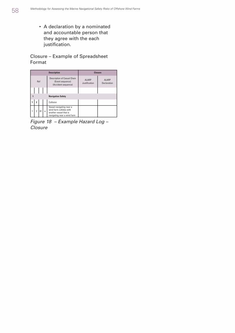
• A declaration by a nominatedand accountable person thatthey agree with the eachjustification.
Closure – Example of SpreadsheetFormat
Figure 18 – Example Hazard Log –Closure
58 Methodology for Assessing the Marine Navigational Safety Risks of Offshore Wind Farms
RefDescription of Casual Chain
(Event sequence)(Accident sequence)
ALARPJustification
ALARPDeclaration
Description Closure
1 2
1 012 a
Collision
Vessel navigating near awind farm collides withanother vessel that isnavigating near a wind farm
1 Navigation Safety
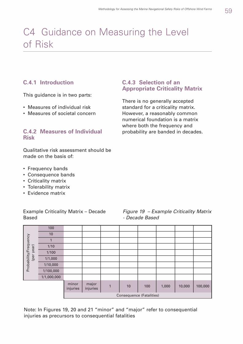
C.4.1 Introduction
This guidance is in two parts:
• Measures of individual risk• Measures of societal concern
C.4.2 Measures of IndividualRisk
Qualitative risk assessment should bemade on the basis of:
• Frequency bands• Consequence bands• Criticality matrix• Tolerability matrix• Evidence matrix
C.4.3 Selection of anAppropriate Criticality Matrix
There is no generally acceptedstandard for a criticality matrix.However, a reasonably commonnumerical foundation is a matrixwhere both the frequency andprobability are banded in decades.
Methodology for Assessing the Marine Navigational Safety Risks of Offshore Wind Farms 59
C4 Guidance on Measuring the Level of Risk
Pro
bab
ility
/Fre
qu
ency
(p
er y
ear)
1/1,000,000
minorinjuries
Consequence (Fatalities)
majorinjuries
1 10 100 1,000 10,000 100,000
1/100,000
1/10,000
1/1,000
1/100
1/10
1
10
100
Figure 19 – Example Criticality Matrix- Decade Based
Note: In Figures 19, 20 and 21 “minor” and “major” refer to consequentialinjuries as precursors to consequential fatalities
Example Criticality Matrix – DecadeBased
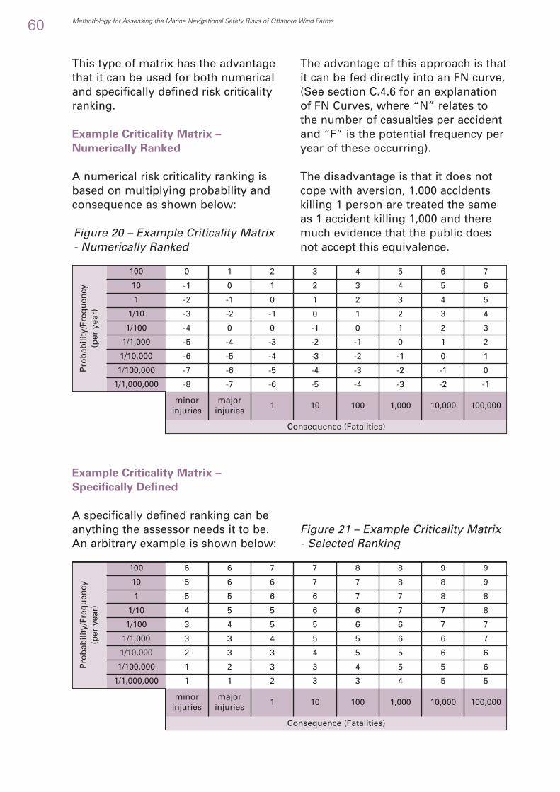
Consequence (Fatalities)
Consequence (Fatalities)
0 1 2 3 4 5 6 7
-1 0 1 2 3 4 5 6
-2 -1 0 1 2 3 4 5
-3 -2 -1 0 1 2 3 4
-4 0 0 -1 0 1 2 3
-5 -4 -3 -2 -1 0 1 2
-6 -5 -4 -3 -2 -1 0 1
-7 -6 -5 -4 -3 -2 -1 0
-8 -7 -6 -5 -4 -3 -2 -1
6 6 7 7 8 8 9 9
5 6 6 7 7 8 8 9
5 5 6 6 7 7 8 8
4 5 5 6 6 7 7 8
3 4 5 5 6 6 7 7
3 3 4 5 5 6 6 7
2 3 3 4 5 5 6 6
1 2 3 3 4 5 5 6
1 1 2 3 3 4 5 5
This type of matrix has the advantagethat it can be used for both numericaland specifically defined risk criticalityranking.
Example Criticality Matrix –
Numerically Ranked
A numerical risk criticality ranking isbased on multiplying probability andconsequence as shown below:
The advantage of this approach is thatit can be fed directly into an FN curve,(See section C.4.6 for an explanationof FN Curves, where “N” relates tothe number of casualties per accidentand “F” is the potential frequency peryear of these occurring).
The disadvantage is that it does notcope with aversion, 1,000 accidentskilling 1 person are treated the sameas 1 accident killing 1,000 and theremuch evidence that the public doesnot accept this equivalence.
60 Methodology for Assessing the Marine Navigational Safety Risks of Offshore Wind Farms
Pro
bab
ility
/Fre
qu
ency
(p
er y
ear)
1/1,000,000
minorinjuries
majorinjuries
1 10 100 1,000 10,000 100,000
1/100,000
1/10,000
1/1,000
1/100
1/10
1
10
100
Pro
bab
ility
/Fre
qu
ency
(p
er y
ear)
1/1,000,000
minorinjuries
majorinjuries
1 10 100 1,000 10,000 100,000
1/100,000
1/10,000
1/1,000
1/100
1/10
1
10
100
Example Criticality Matrix –
Specifically Defined
A specifically defined ranking can beanything the assessor needs it to be.An arbitrary example is shown below:
Figure 21 – Example Criticality Matrix- Selected Ranking
Figure 20 – Example Criticality Matrix- Numerically Ranked

Unlikely (but not exceptional) to happen during the licence period.
Likely to happen (to a wind farm) yearly or more frequently.
No significant harm topeople
The disadvantage is that it cannot befed into an FN curve.
The advantage is that it can cope withaversion.
Criticality Matrix – Selection
The disadvantage of both approachesis that people prefer to judge:
• Risk in a more qualitative way• From fewer probability bands
(often 5).
Therefore, what is suggested is thatthe assessment is based on acriticality matrix that developersbelieve is appropriate for their needs,but that a mapping is made to adecade based risk matrix to allow aFN curve to be generated.
The following is an example of thisbased on a 4x4 IMO matrix.
Methodology for Assessing the Marine Navigational Safety Risks of Offshore Wind Farms 61
Freq
uen
cy
Frequent
Likely to happen during the licence period of a wind farm (nominally 20 years).
Only likely to happen in exceptional circumstances.
ReasonablyProbable
Remote
ExtremelyRemote
Injury to vessels crewInjury to turbine
installation ormaintenance crewInjury on the shore
Loss of a vessel crewmember(s) (1 to 3)Loss of a turbine
installation ormaintenance crewmember(s) (1 to 3)
Fatality(ies) on the shore(1 to 3)
Total loss of a vesselscrew
Total loss of a turbineinstallation or
maintenance crewMultiple fatalities on the
shore
Insignificant
Consequence to People
Minor Major Catastropic
Table 15 – IMO Style Frequency Bands (F)
Table 16 – IMO Style ConsequenceBand – People (C)
IMO Style Frequency Bands
IMO Style Consequence Bands

7
Risk must be mitigated with design modification and/orengineering control to a Risk Class of 5 or lower before consent
7 Unacceptable
Consequence
4
Table 17 – IMO Style Criticality Matrix(CR)
C.4.4 Tolerability Matrix
There is no generally acceptedstandard for a tolerability assessment.However, the following example,using the criticality band 1 to 7 inTable 17, is based on both ReducingRisk Protecting People and paralleltransport risk experience.
62 Methodology for Assessing the Marine Navigational Safety Risks of Offshore Wind Farms
3
5 6
4 5 6
2 3 4 5
1 2 3 4
Frequent
ReasonablyProbable
Remote
ExtremelyRemote
Freq
uen
cy
Insignificant Minor Major Catastropic
IMO Style Criticality Matrix
Risk Criticality Condition Explanation
Risk must be mitigated with design modification and/orengineering control to a Risk Class of 5 or lower before consent
6 Unacceptable
with a commitment tofurther risk reduction before construction
Risk should be mitigated with design modification, engineering and/or administrative control to a Risk Class of 4
or below before construction5
Tolerable withModifications
with a commitment tofurther risk reduction
before operation
Risk should be mitigated with design modification, engineering and/or administrative control to a Risk Class 3 or
below before operation4
Tolerable withAdditionalControls
with a commitment to riskmonitoring and reduction
during operation
Risk must be mitigated with engineering and/or administrativecontrols. Must verify that procedures and controls cited are in
place and periodically checked3
Tolerable withMonitoring
Technical review is required to confirm the risk assessment isreasonable. No further action is required
2Broadly
Acceptable
Technical review is required to confirm the risk assessment isreasonable. No further action is required
1Broadly
Acceptable
Table 18 – Example Risk TolerabilityMatrix (T)

C.4.5 Evidence Matrix
Development in risk assessmenttechniques, since the IMO developedFormal Safety Assessment, haveincluded defining risk as not just acombination of probability andconsequence but as a combination ofprobability, consequence anduncertainty in the assessment ofprobability and consequence asshown in the Figure below (See alsoAppendix A “MCA Formal SafetyAssessment Notes” for anexplanation of this concept).
Figure 22 - Definition of Risk IncludingUncertainty
The purpose is to make sure that risksranked as “low” are scrutinised tocheck that this assessment is valid.
This has been interpreted as a need toassess the quality of the evidenceused to support a probability andconsequence assessment. Anexample of a guide to assessingconfidence for particular risks, in aparticular wind farm and in aparticular scenario is shown in figure23. This indicates how evidencequality, for this particulardevelopment or scenario, may beassessed in an Evidence Matrix.
However, This example matrix shouldnot be taken as a guide to the order ofbest evidence for all risks, in all windfarms and all scenarios. Advice onappropriate evidence for a particulardevelopment may be sought duringinitial discussions with MCA.
Figure 23 – Example Evidence Matrix
Methodology for Assessing the Marine Navigational Safety Risks of Offshore Wind Farms 63
E8
E7
E6
E5
E4
E3
E2
E1
Best Evidence
Worst Evidence
Consequence
Pro
bab
ility
Uncertainty
Current Situation
Trials
Validated Simulations
Quantitative Calculations
Qualitative Analysis
Expert Opinion - Written
Expert Opinion - Verbal
No Evidence

C.4.6 Measures of SocietalConcern
A measure of societal concern is toassess the overall level of risk basedon an FN curve. An example of acurve (with dummy values for a windfarm) is shown below. The areaunder the graph is the aggregatepotential loss of life for the all thehazards in the wind farm itself and ofthose in the sea area that may resultfrom an incident within or close to thewind farm.
Figure 24 - Example FN Curve
64 Methodology for Assessing the Marine Navigational Safety Risks of Offshore Wind Farms
1.00E+01
1.00E+00
1.00E-01
1.00E-02
1.00E-03
1.00E-04
1.00E-05
1.00E-06
1.00E-07
1.00E-08
1.00E-091 10 100 1,000 10,000 100,000
Freq
uen
cy (
F) p
er Y
ear
of
Acc
iden
ts o
f N
or
mo
re F
atal
itie
s
Number of Fatalities (N) or more per accident
FN Curve for Offshore Wind Farm
Potential Loss of Life per year = 0.060

Developers are invited to use thefollowing analysis as a starting pointfor a site specific Influence Analysisincluding any extra site specificinfluences and excluding (with ajustification) influences that are notapplicable.
C.5.1 Influence Analysis
The following sections describe ageneric identification of the influences
on the level of risk. In producing asite specific analysis developersshould use this as a guide:
• Adding site specific influences• Removing (with justifications)
influences that are not applicable
Note: The tables are labelled R1, R2,etc. as the main use of the InfluenceAnalysis is on the assessment or risk.
Methodology for Assessing the Marine Navigational Safety Risks of Offshore Wind Farms 65
C5 Guidance on Influences on the Level of Risk
R1 Risk Factors
1 Site
1. Location of wind farm.2. Alignment of wind farm.3. Layout of wind farm. (E.g. grid, scattered or other layouts)
2 Traffic
1. Traffic routes, density, type and operations.2. Potential growth or decline in traffic.3. Seasonal variation in traffic.4. Special traffic, e.g. dangerous goods, etc.
3 Interrelations Between Vessels
1. Blocking of escape routes or bad weather refuges2. Bunching3. Increase in “crossing” encounters 4. Increase in “end-on” encounters5. Increase in “overtaking” encounters6. Increase in traffic volumes7. Loss of recreational cruising routes8. Pinching9. Reduction in sea room for manoeuvring10. Reduction in water depth for manoeuvring11. Blocking of routes to safe havens and inshore anchorages12. Redirection of recreational craft and fishing vessels into routes used by other
vessels, particularly larger and faster vessels.4 Navigator Behaviour
1. Lengthened navigation routes for leisure craft increase navigator fatigue (andhence error) and increase the criticality of weather windows.
2. Enhanced navigational complexity and need for navigational awarenessincrease fatigue (and hence error)
5 Other single vessel factors
1. Collision with wind farm structures2. Fouling or contact with cables3. Grounding
Table 19 - Risk Factors – Example Checklist

C.5.3 Influences on Causes –Example Checklist for aparticular development (See alsofollowing example check lists.)
Table 20 - Influences on Causes –Example Checklist
66 Methodology for Assessing the Marine Navigational Safety Risks of Offshore Wind Farms
R2 Influence on Causes
1 Vessel Traffic Management
1. Availability of Vessel Traffic Services (VTS).2. Availability of Pilot services.
2 Aids to Navigation
1. Compliance with requirements for Aids to Navigation. (site and vessel)
2. Failure (or non availability) of Aids to Navigation & othersystems
3. Site-specific effects on aids to navigation. E.g. masking bybackground lights, masking by structures and the effects ofrotating blades, control responsibility for foghorns, etc.)
4. AIS (Automatic Identification System) failure or not required to fit.
5. Marking on charts of wind farm structures and associatednavigation aids
3 Bathymetry
1. Accuracy of and changes to bathymetry (e.g. navigable channels,shifting sandbanks, anti-scour material, seabed mobility, etc.)
4 Interference
1. Interference with vessel based communications.2. Interference with shore based communications.3. Interference with vessel based navigation. (E.g. GPS, radar,
compasses etc.).4. Interference to ship based radar e.g. shadowing and blind
sectors and false echoes.5. Interference with shore based navigation. (e.g. VTS services,
MRCC services, etc.)6. Interference to shore based radar e.g. shadowing and blind
sectors and false echoes 7. Similar interference to helicopter and fixed wing aircraft radar
used in SAR and emergency response.8. Electromagnetic interference from turbine generators,
transformers or cables9. Acoustic interference to sonar, diver communications, echo
sounders, fish finders and acoustic release systems10. Helicopter radar contact in a wind farm interpreted as a vessel
contact5 Future Technical Change
1. Application of Radar Absorbing Material to towers and blades, etc.

C.5.4 Traffic Densities and types– Example Checklist
Table 21 - Traffic Levels – ExampleChecklist
C.5.5 Circumstances – ExampleChecklist
Table 22 – Circumstances – ExampleChecklist
Methodology for Assessing the Marine Navigational Safety Risks of Offshore Wind Farms 67
R3 Traffic Levels
1 Hindcast – 1⁄2 consent period (e.g. 10 years)2 Current3 Forecast – 1⁄2 consent period (e.g. 10 years)4 Forecast – full consent period (e.g. 20 years)
R4 Circumstance
1 Intentional Navigation
1. Intentionally navigating within a wind farm en route or to carryout activities.
2 Accidental Navigation
1. Unintentionally navigating within a wind farm or being forced todo so to avoid collision with another vessel, etc.
3 Emergency Navigation
1. Wind farm blocking passage to port of refuge, safe haven,inshore anchorage or inshore routes.
2. Wind farm restricting anchoring.4 Forced Navigation
1. Wind farm forcing passage in more dangerous waters.2. Wind farm forcing passage in more congested water.
C.5.6 Influences on Consequences– Example Checklist
Table 23 - Influences onConsequences – Example Checklist
R5 Influence on Consequence
1 Wind Turbine Design
1. Strength and robustness of wind turbine structure.2. Collapse mode of impacted turbines after collision
2 Vessels
1. Vessel size.2. Vessel cargo. (E.g. polluting cargoes, hazardous cargoes, etc.)
3 Search and Rescue
1. Adequacy of Search and Rescue provision. (E.g. equipment,equipment location, communication, etc.)
2. Availability of Search and Rescue resources. (E.g. currently incommercial use, multiple SAR operations, etc).
3. Ability to deploy Search and Rescue resources. (E.g. helicopteroperations affected by blade rotation, aircraft operations affectedby search height restrictions, etc.)
4 Emergency Response
1. Adequacy of Emergency Response provision. (E.g. tugs, oil spillequipment, communications, etc.)
2. Availability of Emergency Response resources. (E.g. currently incommercial use, multiple ER operations, etc).
3. Ability to deploy Emergency Response resources. (E.g. state ofcontingency planning)

This annex gives guidance on
• Targets for safety• Interpretation of “broadly
acceptable” in an ALARP Justification• The tolerability of risk.
C.6.1 Targets for Safety
The UK Government does not itself settargets for safety. Effectively, these areset by criminal and civil case law afteraccidents. However, this section setsout some guidelines that can be usedin assessing tolerability.
C.6.2 Interpretation Of “BroadlyAcceptable” in an ALARPJustification
The regulatory background to theNavigation Safety Goal is based on theUK Health and Safety Executivedocument “Reducing Risks ProtectingPeople” (RRPP), a guide to the HSE’sdecision-making process16. Thedocument is aimed at explaining thedecision-making process of the HSE17
and therefore contains much usefulinformation on risk-based decision-making. It is a large document (80pages) covering:
• Part 1: Overview of risk and riskmanagement issues
• Part 2: Review of developments thathave influenced the HSE’s decision-making approach
• Part 3: Approach to reachingdecisions on risk
• Appendix 1: Some of theconventions adopted for undertakingrisk assessments
• Appendix 2: Identifying andconsidering options for newregulations, Approved Codes ofPractice and guidance
• Appendix 3: Some issues relevant toassessing risk reduction options
• Appendix 4: Some statistics forcomparing risks from differenthazards.
The purpose of this section is to extractthe key points of the document that areapplicable to offshore renewableenergy installations.
C.6.3 Tolerability of Risk
At its heart RRPP sets out to provide amechanism for a regulator to “satisfythe public that industry, in takingadvantage of technological advancesand in responding to economicpressures, will not be allowed toimpose intolerable risks on people”18.In doing so it sets out the frameworkfor decision-making based “Tolerabilityof Risk”19 and defines bands ofunacceptable, tolerable and broadlyacceptable.
It then expands on this framework bydefining what is expected whendeciding on whether a risk is:
68 Methodology for Assessing the Marine Navigational Safety Risks of Offshore Wind Farms
C6 Guidance on the Tolerability ofResidual Risks
16 Reducing Risks Protecting People (RRPP or R2P2), ISBN 0 7176 2151 0, available as a download from www.hse.gov.uk/risk/theory/r2p2.htm 17 RRPP page vi 18 RRPP page 1 19 RRPP page 3

• Unacceptable; or• Tolerable; or• Broadly acceptable.
Figure 25 - HSE Framework for theTolerability of Risk
This is summarised as:
• The level of individual risk and thesocietal concerns must be taken intoaccount
• The actions taken are inherentlyprecautionary
• Risk assessment is required todetermine the risk control measures
• Suitable controls are in place• Controls, as a minimum, must
achieve the standard of relevantgood practice precautions
• Some risks are unacceptable andthe activity ruled out unlessmodifications can be made
• As controls are introduced theresidual risks may fall so low thatadditional measures to reducethem further are likely to begrossly disproportionate to therisk reduction achieved
• Control measures should bemonitored in case risks changeover time.
From this three main issues emerge:
• At what point does a risk become“Broadly Acceptable”?
• What is included in “Relevant GoodPractice”?
• What is “Grossly Disproportionate”?
Defining what is Broadly Acceptable
In defining “broadly acceptable”, theRRPP notes that “the way we all treatrisks depends on our perception ofhow they relate to us and the things wevalue” and that for man-made hazardson “how well we see the process(giving rise to the hazard) isunderstood, how equitable the dangeris distributed, how well individuals cancontrol their exposure and whether therisk is assumed voluntarily”20.
The RRPP states that the “HSE believesthat an individual risk of death of onein a million per annum for bothworkers and the public corresponds toa very low level of risk and should beused as a guideline for the boundarybetween the broadly acceptable andtolerable regions”21.
It then notes that this level is“extremely small when compared tothe background level of risk”.
Defining Relevant Good Practice
RRPP defines relevant good practice. Itconsiders as authoritative sources“those enshrined in prescriptivelegislation, approved codes of practiceand guidance produced byGovernment”. It also considersincluding as other sources of goodpractice “standards produced byStandards-making organisations (e.g.BS, CEN, CENELEC, ISO, IEC, ICRP) andguidance agreed by a bodyrepresenting an industrial oroccupational sector (e.g. tradefederation, professional institution,sports governing body)” 22.
Methodology for Assessing the Marine Navigational Safety Risks of Offshore Wind Farms 69
Incr
easi
ng
ind
ivid
ual
ris
ks
and
so
ciet
al c
on
cern
s
Unacceptableregion
Tolerableregion
Broadly acceptableregion
20 RRPP page 11 para 2021 RRPP page 45 para 13022 RRPP page 50 para 142

RRPP then goes on to say thatexperience suggests that, “in mostcases adopting good practice ensuresthat the risks are effectivelycontrolled”23. It then immediatelyqualifies this by stating that there willbe cases where existing best practicewas either “not identified” or has beenfound to “result in inadequate controlof risk”24.
RRPP also makes a distinction betweengood practice and best practice25. Ineffect, good practice is mandatory, butbest practice is voluntary, unlesscomplying with best practice is used aspart of a tolerability argument.
In wind farm marine navigationalsafety terms this raises the issue thatexisting good practice risk measureshave been extended to cover windfarms and are not yet validated byeither experience or simulation andtherefore may require retrospectiverevision.
There are gaps in good practice and asa result new practices will bedeveloping and may requireretrospective application.
Defining Grossly Disproportionate
RRPP also defines “GrosslyDisproportionate” and its associated“Reasonably Practical” which aredriven by case law and it is “ultimatelya matter for the courts to decide”. Ananalysis of case law shows that thecourts “will look at all relevantcircumstances, on a case by case basis,when reaching decisions on theappropriateness of action taken”26.Therefore all RRPP does is give astructure to possible ReasonablyPractical and Grossly Disproportionatearguments.
It suggests that the starting pointshould be the present situation (or ifthis is not possible an option which isknown to be reasonably practical). Riskand Risk Control Options should thenbe considered against this startingpoint to determine if the “reasonablyforeseeable”27 risks have reduced tothat which is As Low As ReasonablyPractical (the ALARP test). Furtheroptions should be considered todetermine if there is a grossdisproportion between the cost of theoption and the reduction in risk (theGross Disproportion test28).
The Gross Disproportion Test
As a guide to making ALARP and GrossDisproportion assessments, it givesguidance on both valuing the benefitsand assessing the costs. Where thebenefit is the prevention of death itdefines a Value of Preventing aFatality29 (VPF) and adopts a benchmarkvalue of £1,000,000 (2001 prices).
In assessing costs, case law groupsthem as money, time and trouble30
though does not give a mechanism forcomparing cost time and money. Thecost of the measures required can beassessed to derive a Cost of Preventinga Fatality31 (CPF). The cost has to bemade up of those that are incurredunavoidably by health and safetymeasure less any gains made from thesame measure32. The ability to afford acontrol measure is not a legitimatefactor in the assessment of costs33.
It then goes on to say that comparisonof the CPF with the VPF may “wellreveal a difference between them34” butdoes not define Gross Disproportion inany numerical way.
70 Methodology for Assessing the Marine Navigational Safety Risks of Offshore Wind Farms
23 RRPP page 50 para 143 24 RRPP page 50 para 145 25 RRPP page 36 para 101 bullet 2 26 RRPP page 62 para 3 27 RRPP page 63 para 6 28 RRPP page 63 para 529 RRPP page 65 para 13 30 RRPP page 62 para 4 31 RRPP page 65 para 15 32 RRPP page 66 para 19 33 RRPP page 67 para 19 bullet 3 sub-bullet 434 RRPP page 65 para 15

D.1.1 Introduction
In their assessments and submissionsdevelopers will be expected toundertake appropriate assessment insupport of their navigation riskassessment. This could also beextended to cover some aspects ofsearch and rescue and emergencyresponse if this is required by MCA.
This Annex gives an overview of the:
• Purpose of the appropriateassessment in a Developer’sassessment and submission.
• Types of appropriate assessment,for example modelling, sought forin a Developer’s assessment andsubmission.
• Hierarchy of assessment techniquesappropriate to a Developer’sassessment and submission.
• Concept of a scenario to control thescope and depth of the appropriateassessment.
The Annex then includes:
• Guidance on Navigation RiskAssessment
• Area Traffic Assessment• Specific Traffic Assessment
Note: Guidance on appropriatesearch and rescue overview andappropriate emergency responseoverview can be found in sections 3.5and 3.6 of this document.
D.1.2 Purpose of an AppropriateAssessment Technique in RiskAssessment
The purpose of the appropriateassessment is to:
• Prove Feasibility• Demonstrate that the navigation
activities (or search and rescueand emergency responseactivities) are feasible, with thewind farm structures in place,during the phase ofdevelopment, for the vesseltypes and with the conditions.
• Quantify Risk• Produce a quantitative or
qualitative value, acceptable toGovernment, of the change inrisk caused by the developmentto the base risk associated withthe activity and how this riskvaries across vessel types.
• Assess Sensitivity• Determine the sensitivity of the
risk to the conditions and therisk factors.
• Decide on risk controls• Identify, evaluate and decide on
appropriate risk controls.
Methodology for Assessing the Marine Navigational Safety Risks of Offshore Wind Farms 71
D1 Overview of Appropriate RiskAssessment

• Widely defined to cover a range ofsituations in a single scenario
• Applicable to generate reasonableestimations of feasibility, risk,sensitivity and the effect of controls.
D.1.6 Hierarchy of theappropriate assessment insupport of Navigation RiskAssessment
The concept of the methodology is ofa hierarchy of appropriateassessment, including numericalmodelling, which starts at the arealevel and the results used to define, ifnecessary, more specific issues to beinvestigated.
For example the process followed tosupport the navigation riskassessment of a particular proposalmight be:
1a Area Traffic Assessment of the
Strategic Area
leading to
1b Area Traffic Assessment of the Wind
Farm Area
leading to where necessary
2a Specific Traffic Assessment in and
around the Wind Farm Area
leading to (where necessary and
appropriate to the development
proposal)
2b Specific Traffic Simulation in and
around the Wind Farm Area
leading to (where necessary and
appropriate to the development
proposal)
3 Specific Traffic Bridge Control
Simulation in and around the Wind
Farm Area for training and research
purposes
leading to ( where necessary and
appropriate to the development
proposal))
4 Site Specific Trials
Table 24 – A Possible Hierarchy ofAssessment and Trials in support ofNavigation Risk Assessment
D.1.3 Purpose of theAppropriate Assessment inHazard Log Closure
In addition, the discipline of theappropriate assessment technique isto be used to identify issues that needto be considered to:
• Close the hazard log• Develop the risk control log.
D.1.4 Types of appropriateassessment
Depending on the proportionalityjudgement, leading to the scope anddepth of the submission, thefollowing types of other appropriateassessment, for example numericalmodelling, may be needed:
• In support of navigation riskassessment
• Area Traffic Assessment• Specific Traffic Assessment
• For search and rescue andemergency responses assessmentssee Sections 3.5 & 3.6.
D.1.5 Concept of the Scenarioto Control the Scope and Depthof the appropriate assessment
The various hazards identificationswill generate a large number ofsituations that require furtherinvestigation.
The concept of the scenario is to setup a model (or assessment), thatwhile it is not necessarily an exactrepresentation of the situations beingassessed is sufficiently:
72 Methodology for Assessing the Marine Navigational Safety Risks of Offshore Wind Farms
Increasin
g H
um
an In
volvem
ent

Definition 1 – Area Traffic Assessment
Area Traffic Assessment assesses themarine environment, the traffic andthe wind farm development to predictthe risk of collision, contact,grounding and stranding now and inthe future. If appropriate it may needto be statistical in nature, in any casebased on assessing the vessel trafficand the behaviour of vessels withrelation to steering rules, speedchanges, the route they wish tofollow, etc., and the multipleinterrelationships with a large numberof vessels, of different types,navigating in the same environmentover a long time and involved in avariety of operations which will eachinteract.
Definition 2 - Specific Traffic
Assessment
Specific Traffic Assessment might beused to assess in detail the risk ofmore specific navigation issues, andproposed risk controls, that couldrequire a higher quality assessmentand representation of:
• The manoeuvring capabilities of thevessels, including such parametersas their stopping distances andturning circles
• Changes which may result in themariners’ domain size asmanoeuvring sea room reduces
• Details of the bathymetry.
It may also be of value to use aNavigation Simulator to trainmariners in the navigation andoperation of their vessels within andclose to wind farms. Research couldalso be carried out, by driving theship in real time, in conjunction withother instructor / assessor controlled
target vessels in encounter situations,to assess the feasibility and level ofrisk. This might include the risk ofgrounding or collision or contact withother vessels and structures withinthe wind farm or in nearby restrictedwater navigable channels. Suchtraining or research should alsoinclude the ability for mariners tonavigate in all circumstances usingsimulated radar and ARPA displays,as appropriate to their vessel types,integrated with the vessel controlsimulator and other simulatednavigation and communicationsystems.
Simulators used to assessnavigational risk in and near tooffshore wind farms must be capableof simulating all the navigationaleffects and phenomena relevant to, orpeculiar to, offshore wind farms.These include, for example, theeffects of wind farm structures onvessel and shore based radarsystems.
Any simulators used should complywith Section A- I/12 (“Standardsgoverning the use of simulators”) ofthe International Convention onStandards of Training, Certificationand Watchkeeping, 1978 as amendedin 1995 and to date (“STCWConvention”, IMO)
Note: The Instructors and Assessorsoperating the simulator/s should bequalified and experienced as specifiedin Section A-I/12 Part 2 subsection 9of that Convention (“Qualifications ofinstructors and assessors”).
For non-critical assessments MCAmay grant permission for systemsand personnel not reaching thesestandards and qualifications to
Methodology for Assessing the Marine Navigational Safety Risks of Offshore Wind Farms 73

operate acceptable proprietarysystems in mutually agreed scenarios.Such permission should be soughtfrom MCA by developers before theassessment takes place.
Some of the parameters worked outin this way may then be used in thedefinition of “rules” in the Area TrafficModelling/Assessment.
Definition 3 - Specific Traffic Full
Bridge Control Simulation
For critical risks or significantinvestment decisions on risk controloptions it may be necessary to extendthe assessment to simulation usingfull bridge simulators. A number ofUK marine training and researchestablishments, together with someuniversities, have such systems.
Definition 4 – Site Specific Assessment
Any numerical modelling, navigationsimulator systems or otherassessment techniques used in therisk assessment of a specificdevelopment will, singly or incombination with other tools andtechniques, be required to fully:
a) Include bathymetric and other sitefeatures data for the area using anElectronic Navigational Chart(ENC) base map or as determinedby a site-specific survey. Inparticular, depth contours andnavigation channels relevant tovarious vessel types, sizes andoperations should be taken intoaccount with respect to thepotential for colliding with othervessels or wind farm structuresand for grounding due to thelimitations of water space orwhilst avoiding a collision;
b) Model or assess the effects of tideand tidal streams in the wind farmarea, plus any local currents so asto determine their effects onnormal manoeuvring andoperations and on vessels notunder command, SAR, pollutioncontrol, etc;
c) Model or assess the effects onnavigation and marine operationsof various weather conditionssuch as wind, sea state andvisibility;
d) Use the survey traffic datasupplied by the developers andother sources, including the DTIMarine Traffic Database, from acombination of radar surveys,Automatic Identification System(AIS) data and historical records;
e) Model or assess typical fishingand recreational activities withinand close to the wind farm site, asin (d) above and their interactionwith other vessel types navigatingnear and within the wind farm.Such requisite background data tobe supplied from the developersand other sources;
f) Model or assess each vessel typewith suitable draughts, dynamicsand domains or equivalentparameters;
g) Establish a baseline of marineactivity without a wind farm;
h) Examine the effects of the windfarm on this marine activity andtraffic if no re-routeing isrecommended;
i) Model or assess the chain ofnavigational events as vesselspass within or close to the windfarm (i.e. where an alteration ofcourse or speed made in anencounter with a turbine or othervessel produces a furtherencounter or encounters,including the avoidance of
74 Methodology for Assessing the Marine Navigational Safety Risks of Offshore Wind Farms

grounding in confined channelsand shallow water effects);
j) Model or assess the effect of thewind farm on the necessarycompliance of various vesseltypes to all of the InternationalRegulations for the Prevention ofCollisions at Sea 1972, asamended, (The CollisionRegulations or “COLREGS”) (e.g.power to sail, sail to fishingvessel, overtaking vessels, etc.)and to any local rules if the sitelies within the area of anappropriate local authority;
k) Examine the cumulative effects ofall wind farms, aggregatedredging, other offshoreinstallations etc., within theproximity of the given site, giventhe traffic data by developers andthe DTI Marine Traffic Database;
l) Recommend optimum routesbased on the foregoingassessments if these are seen tobe required;
m) Determine, on request, theincreased passage distancesproduced by re-routeing ofspecific vessels;
n) Allow for power and steeringfailures within and close to thewind farm together with suitableresearched allowances for humanerror;
o) Include the effects of the windfarm on the detection of othervessels within or on the far side ofit, such effects to include visualblind areas and radar effects suchas shadow and blind sectors,spurious echoes and other effects,etc using the typical beam widths,pulse lengths and powers of thevessel type radars involved;
p) Model all vessel types’compliance with CollisionRegulations Rule 19 in relation tosub para (o) above;
q) Apply such effects to relevant portand Vessel Traffic Services (VTS)radar sites;
r) If required by MCA, investigatethe wind farm effects onhelicopter SAR and fixed wingaircraft dispersal operations, etc.,particularly any radar or thermalimaging effects;
s) Examine the hazards and theconsequences of major incidentswithin or close to the wind farmincluding wreck, collisioninvolving large passenger vessels,etc;
t) Include data and an overview ofthe consequences and control ofoil and other pollutant spills;
u) Suggest a possible safety zone tobe applied to specific or all vessel types within and around the windfarm;
v) Recommend minimum separationdistances of the specific windfarm boundaries from establishednavigational routes, from portapproaches, from routeingschemes, from other wind farmsand from other offshoreoperations (see the MCA websitefor initial guidance);
w) Make navigational riskrecommendations with respect tothe construction anddecommissioning phases of thedevelopment;
x) Include an overview of potentialsearch and rescue activities anddifficulties within and close to thewind farm.
Methodology for Assessing the Marine Navigational Safety Risks of Offshore Wind Farms 75

The purpose of this annex is to giveguidance on how to select ModellingTools or other Assessment Techniquesthat are, or will be, acceptable toGovernment.
This Annex describes:
• The Process of Selection ofAssessment Techniques
• How to obtain MCA approvalincluding the:
• Self declaration process• Extent of the process• Activities required• Information required
• The Method of Describing in theSubmission the Techniques andTools Used.
D.2.1 Process of Selection ofAssessment Techniques andtools
• The Assessment Techniques andtools used shall have beensubmitted to the MCA for approval,including a self-declaration.
• Whichever technique or tool isselected, the user is stronglyrecommended to consult with theMCA prior to its use in a specificassessment.
D.2.2 Approved Wind FarmTools and AssessmentTechniques
“Approved Wind Farm Tools andAssessment Techniques” are thosewhich are granted approval, by theMCA, for use with wind farms, andwhich will subsequently join the list ofthose having previously havingobtained such approval.
D.2.3 How to Obtain MCAApproval for Tools andAssessment Techniques
The process of gaining MCA approvalmay consist simply of a self-declaration of the Verification35 of theTools and Assessment Methods.
Extent of Self Declaration
The extent of this process will dependon the development status of eachtool and assessment method. Thisstatus is categorised as:
• Approved maritime tools andassessment techniques designed ormodified specifically for assessingnavigational risk within and near towind farms (Type D1)
• Widely and publicly used maritimetools and assessment techniques(Type D2)
76 Methodology for Assessing the Marine Navigational Safety Risks of Offshore Wind Farms
D.2. Guidance on the Selection ofTechniques that are Acceptable toGovernment
35 Verification: Confirmation through the provision of objective evidence, such as examination by or demonstration to the verifier, that specified requirementshave been fulfilled. In software development, verification is the process of evaluating the (software) products of a given phase, or segment of work, to ensurecorrectness and consistency with respect to the products and standards provided as input to that stage. (ISO 9000:2000 TickIT guide)

• Specialist maritime tools andassessment techniques (Type D3)
• Non marine tools and assessmenttechniques (Type D4)
• New tools and assessmenttechniques (Type D5).
List of Approved Maritime Tools and
Assessment Methods (Type D1)
These are either:
• Tools and assessment techniquesdesigned or modified specifically forassessing navigational risk withinand near to wind farms approvedby the MCA for use with themaritime environment
• Tools and assessment techniquesdesigned or modified specifically forassessing navigational risk withinand near to wind farms andapproved by third party bodiesacceptable to MCA for use with themaritime environment
Definitions
Widely and publicly used maritimemodelling tools and assessmenttechniques (Type D2) are either:
• Maritime modelling tools orassessment techniques that arecommercially available, qualitycontrolled, with a proven trackrecord and a large user base, butnot necessarily with reference tooffshore wind farms or otheroffshore structures.
Or• Maritime modelling tools or
assessment techniques that are notcommercially available but arequality controlled, have a proventrack record and have been used ona large number of applications or
projects, but not necessarily withreference to offshore wind farms orother offshore structures.
Specialist maritime modelling toolsand assessment techniques (Type D3)are:
• Maritime modelling tools andassessment techniques that havebeen built up by a single user (orsmall group) and have been usedon other specialist projects.
Non-maritime modelling tools andassessment techniques (Type D4) areeither:
• Modelling Tools and AssessmentTechniques that are commerciallyavailable and quality controlled butare capable of being used in a newway or domain
• Modelling Tools and AssessmentTechniques that are notcommercially available but arequality controlled but are capable ofbeing used in a new way.
The development of new modellingtools and assessment techniques(type D5) is to be encouraged.However, by their nature they willrequire more evidence of verification.
D.2.4Specific Activities toObtain Approval of Tools andTechniques
Depending on the status of the toolsand techniques the activities to obtainapproval shall include reasonedarguments and evidence for some, orall of, the following stages:
• Statement of tool applicability• Clarification of conceptual model
Methodology for Assessing the Marine Navigational Safety Risks of Offshore Wind Farms 77

• Documented model/commentedcode
• Demonstration of abilities• Peer/expert review• Comparison with real-world
experience.
Statement of Tool Applicability
Explain how the tool is applied to thespecific wind-farm assessment task.State how assumptions inherent inthe tool affect the application to thewind farm task.
Clarification of Conceptual Model
Document the conceptual model.This documentation should include:
• Objective(s)• System structure/configuration• Detailed description of the tool, and,
if using numerical techniques, itsalgorithms.
• Logical rules & flow charts• Input data sources.
Documented Model / Commented
Code
• Provide evidence that computermodelling tool code is sufficientlydocumented to enable anothercompetent person to see how itcorresponds to the conceptualmodel.
Demonstration of Abilities
• If required, demonstrate toGovernment departments andagencies the capabilities of themodelling tool or other assessmenttechnique
Peer / Expert review
• Provide evidence that the modellingtools or other assessmenttechniques have been peerreviewed by government approvedperson or persons.
Comparison with Real-World
Experience
• Provide evidence that the modellingtools or other assessmenttechniques have been compared toreal-world experience in similarapplications.
78 Methodology for Assessing the Marine Navigational Safety Risks of Offshore Wind Farms

D.2.5 Specific InformationRequired to Obtain Approval ofModelling Tools or otherAssessment Techniques
The scope of information that shouldbe included with the Self-Declaration:
Table 25 – Self-Declaration Information
Depth of Information
The depth of information required isdependent on the level of:
• Risk the tool or technique isassessing.
• Control (if any) the tool or techniquehas on the risk.
Level of risk and control is likely torange from:
Methodology for Assessing the Marine Navigational Safety Risks of Offshore Wind Farms 79
D1 Maritime Modelling Tools and TechniquesApproved for Application to Offshore Wind Farms
• •
• • •
• • • • • •
• • • • • •
• • • • • •
D2 Widely and Publicly Used MaritimeModelling Tools and AssessmentTechniques
D3 Specialist Maritime Modelling Tools andAssessment Techniques
D4 Non Marine Modelling Tools and Assessment Techniques
D5 New Modelling Tools and AssessmentTechniques
Stage
Dem
on
str
ati
on
Sta
tem
en
t o
f To
ol
Ap
plicab
ilit
y
Cla
rifi
cati
on
of
Co
ncep
tual
Mo
del
Do
cu
men
ted
Mo
del
/
Co
mm
en
ted
Co
de
Pe
er
/ E
xp
ert
Revie
w
Co
mp
ari
so
n w
ith
Real
Wo
rld
Exp
eri
en
ce
• Highest• Navigation tools used in real
time navigation monitoring andmanagement (also, ifappropriate, SAR Tools used inreal time search planning)
• High• Specific navigation situation
tools used to evaluate high riskconditions and advise onimportant controls (also, ifappropriate, SAR tools used inadvance search planning)

To • Medium
• Specific navigation tools used toevaluate medium risk conditions
• Marine traffic assessment toolsuses to assess marine risk
• Low• Marine traffic assessment tools
used to assess the economicimpact of changed shippingroutes.
It is up to the tool user to assess thelevel of risk and the level of controland provide an appropriate depth ofinformation. IEC61508 may be usedas a guide.
D.2.6 Specific InformationRequired when Describing theTools and AssessmentTechniques Used
The description of the modelling toolsand other assessment techniquesused (or proposed to be used) shouldinclude:
• The modelling tool name• Including the version number of
the software
• The application that the tool orassessment technique is supportinge.g.
• Supporting marine trafficassessment, specific navigationsituation assessment, SARresource planning, SARresponse planning, oil spillassessment
• Which wind farm or wind farmarea
• Description of the modelling toolconcept
• Description of prior use of the tool• In wind farm, marine and other
applications• Any pre or post processing software• The hardware the modelling tool
will be run on• The approval status
• Including reference to 3rd partycertificates
• The self-declaration status.
D.2.7 Specific InformationRequired when Describing theAssessment Methods Used
The following is an example of anassessment method description form.
80 Methodology for Assessing the Marine Navigational Safety Risks of Offshore Wind Farms
Assessment Method Description
Name of Method
Use of Method
Method Type (D1 to D5)
Concept of Method
Prior Use of Method
Pre or post Processing
Other relevant information
Table 26 - Example of Technique orTool Description

The purpose of this annex is to giveguidance on how to demonstrate thatthe result from applying the selectedtechniques are, or will be, acceptableto Government.
This Annex describes:
• The process for self-declaration ofvalidated36 results
• Self-declaration activities• Sources of real world information.
D.3.1 Process for Self-declaration of Validated Results
The submission shall include a self-declaration that the results have beenvalidated.
For each validation activity on theresults, a declaration should be madethat presents the results and findings,together with a clear statement. An example format of a validationstatement is given below. Onestatement can be made to cover amultiple set of results.
Example Format of a Validation
Statement
Methodology for Assessing the Marine Navigational Safety Risks of Offshore Wind Farms 81
Heading Description
Validation activity
Results produced by (staff member)
Results produced on (date)
Pre or post Processing
Simulation parameter settings (if relevant)
Comparison data (where relevant) description & source
Validation Conclusion
Figure 26 - Example Format for aValidation Statement
D.3. Guidance on the Demonstration thatthe Results from the Techniques areAcceptable to Government
36 Validation: Confirmation or ratification through the provision of objective evidence that the requirements for a specific intended use or application have beenfulfilled. (ISO 9000:2000 TickIT guide)

D.3.2 Self Declaration -Activities
For all results presented, thedocumentation of results validationshall include reasoned arguments andevidence for the following:
• Tuning of parameters• Consistency checks• Behavioural reasonableness• Sensitivity analyses• Comparison with real-world
experience.
Tuning of Parameters
The submission should provideevidence that the modelling or otherform of assessment has been carriedout appropriately. Different methodshave different parameters so thetuning required will differ. However,three key components, applicable inmost models, are:
• Choice of mathematical routines;choice of appropriate integrationalgorithms & statistical estimators
• Convergence; increasing theresolution in a control dimensionuntil changes of results are withinsatisfactory magnitude. .
• Mathematical formulae fitted todata should have some measure ofgoodness-of-fit calculated.
Consistency Checks
The submission should provideevidence that at key points (typicallyat the end), values of all parametersshould be output & demonstrated thatthey are correct/consistent with theinput. This checks that no inadvertentchanges happened in the coding orrunning.
Similarly, variable distributions usedshould be checked.
Behavioural Reasonableness
The submission should provideevidence that the assessment hasbeen exercised under a range ofconditions and demonstrate that theresults were reasonable.
• This is mainly a qualitative exercisebut it should be checked thatvariables stay within their bounds.For example, key values of variablessuch as vessel speed, as simulated,should be compared with the inputdata
• The conditions simulated shouldinclude some extreme events; moresevere than the events to besimulated for real. Reasonablebehaviour under extreme conditionsgives good confidence in the resultsfor less severe conditions.
Sensitivity Analyses
The submission should provideevidence that the key inputparameters have been varied by smallamounts to determine the sensitivityof the results to changes in theseinputs, and that the sensitivity hasbeen examined for reasonableness.
• This sensitivity analysis is especiallyimportant for input parameterswhere there is uncertainty aroundthe correct value to use.
Comparison with Real-World
Experience
The submission should provideevidence that results have beencompared with real-word experience.
82 Methodology for Assessing the Marine Navigational Safety Risks of Offshore Wind Farms

• Real-world experience may be inthe form of data from controlledexperiments (e.g. trial manoeuvringof a ship) or data from naturalexperiments (e.g. statistics onmarine accidents)
• Wherever real world experience ispresented, it shall include estimatesof uncertainty (data validity)
• Care should be taken in calibratingto fit results to real-worldexperience. While calibrationimproves the comparison with aspecific case, it reduces thegenerality.
• State all calibrations applied to themodel during validation.
If comparison with real-worldexperience is not possible, thedeveloper shall justify why this is so.
• This model-to-model validation isnot as thorough as model-to-real-world validation (both models maybe wrong), but may be acceptable.The greater the difference in thetwo types of models compared, thegreater the confidence in the resultif they agree. A good examplewould be comparison between acomputer simulation & a physical(test tank) model.
D.3.3 Sources of Real WorldInformation
HM Coastguard
HM Coastguard (HMCG) keepsrecords of incidents where they havebeen involved in the co-ordination ofsearch & rescue activities. As HMCGis responsible for coordinatingmaritime emergency calls &responses in the UK Search andRescue region, this should be a
comprehensive dataset for incidentswhere the Coastguard has beenalerted. It is possible that someincidents are handled by otherindividuals/organisations andtherefore not included in this data, butthis is thought to be a smallproportion when considering the seaareas potentially affected by windfarms.
HMCG database records includeincident date, location, vessel type &incident type. Some data will befreely available.
Contact: Risk Analysis & PreventionBranch, tel. 02380 329323 / 329206Additionally, for specific areas, HMCoastguard Maritime Rescue Co-ordination Centres or MaritimeRescue Sub Centres (MRCC / MRSC)may be able to help with localknowledge.
Note: HM Coastguard centres shouldnot however be invited to offer formalopinions on navigational riskassessments. Such opinions shouldbe sought only from MCA’sSouthampton Headquarters,Navigation Safety Branch.
Marine Accident Investigation Branch
(MAIB)
The Marine Accident InvestigationBranch (MAIB) issue statistical reportson marine accidents (freely availablevia the web page, below) and can alsoprovide, on request, statistics brokendown to date, location, vessel type &accident type. Some data will befreely available.
Contact: http://www.maib.gov.uk/
Methodology for Assessing the Marine Navigational Safety Risks of Offshore Wind Farms 83
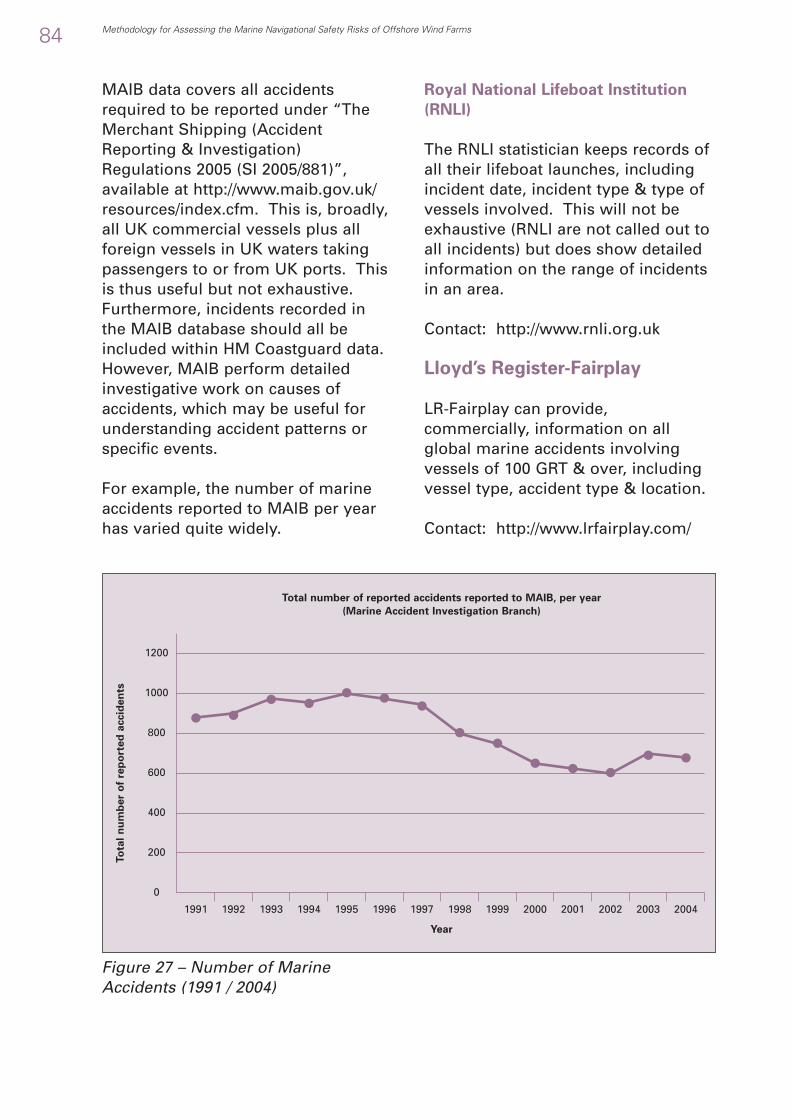
MAIB data covers all accidentsrequired to be reported under “TheMerchant Shipping (AccidentReporting & Investigation)Regulations 2005 (SI 2005/881)”,available at http://www.maib.gov.uk/resources/index.cfm. This is, broadly,all UK commercial vessels plus allforeign vessels in UK waters takingpassengers to or from UK ports. Thisis thus useful but not exhaustive.Furthermore, incidents recorded inthe MAIB database should all beincluded within HM Coastguard data.However, MAIB perform detailedinvestigative work on causes ofaccidents, which may be useful forunderstanding accident patterns orspecific events.
For example, the number of marineaccidents reported to MAIB per yearhas varied quite widely.
Royal National Lifeboat Institution
(RNLI)
The RNLI statistician keeps records ofall their lifeboat launches, includingincident date, incident type & type ofvessels involved. This will not beexhaustive (RNLI are not called out toall incidents) but does show detailedinformation on the range of incidentsin an area.
Contact: http://www.rnli.org.uk
Lloyd’s Register-Fairplay
LR-Fairplay can provide,commercially, information on allglobal marine accidents involvingvessels of 100 GRT & over, includingvessel type, accident type & location.
Contact: http://www.lrfairplay.com/
84 Methodology for Assessing the Marine Navigational Safety Risks of Offshore Wind Farms
1991
0
200
400
600
800
1000
1200
1992 1993 1994 1995 1996 1997 1998 1999 2000 2001 2002 2003 2004
Year
Total number of reported accidents reported to MAIB, per year
(Marine Accident Investigation Branch)
To
tal
nu
mb
er
of
rep
ort
ed
accid
en
ts
Figure 27 – Number of MarineAccidents (1991 / 2004)

D.4.1 Use of Area TrafficAssessment Techniques
Area Traffic Assessment will berequired when there is uncertaintyover the effect of the wind farm onthe ability of vessels to navigate andoperate in the waters adjacent to andthrough the wind farm withoutsuffering an increase in risk. Such riskwill include amongst others the risksof contact, collision, grounding andstranding.
Fundamental Requirements of Area
Traffic Assessment
The fundamental requirements of AreaTraffic Assessment include that it:
• Assesses all traffic in both thestrategic wind farm area (ifappropriate for the particulardevelopment) and the wind farmarea itself.Assesses the movement of vesselsthrough the water in a way that isrepresentative of vessel navigationand activity.Assesses the real world behaviourof the vessels to the CollisionRegulations including
• The effect of reduced visibilityon compliance with theCollision Regulations coupledwith the expected effects onvessel and shore based radars.
• A representative rate of humanerror in applying the CollisionRegulations
• A representative rate ofdeliberate non compliance withthe Collision Regulations
• Assesses the effect of manoeuvringin restricted waterways (definedfrom bathymetric data developedfrom Electronic Navigation Chartsor from site specific surveys)including action by vessels to avoidshallow water
• Is used to calculate: -• As a minimum the frequency
and density of interactionbetween vessels, vessels andshallow water, and vessels andwind farm structures, to gainstatistically significantinformation to assess the effectof the fundamental risk controloptions of location, alignment,size and layout
• The probability of collision,contact, and grounding
• For specific vessel types the riskand tolerability of the risk.
Methodology for Assessing the Marine Navigational Safety Risks of Offshore Wind Farms 85
D.4 Guidance on Navigation RiskAssessment – Area Traffic AssessmentTechniques

D.4.2 How to select theSituations Requiring Area TrafficAssessment
Source of the Situations
The situations requiring assessmentwill come from the:
• Need to evaluate the general effectof the wind farm on the marinetraffic and
• The navigational risksassociated with a development
• The cumulative navigation risksassociated with thedevelopment and the otherwind farm developments andother types of marine activity inthe Strategic Wind Farm Area.
• The in-combination effects onthe navigation risk of thedevelopment with othereconomic developments overthe operational life of the windfarm.
• The need to evaluate the specificimpact of the Wind Farm due to thepresence of specific marine trafficactivity that may be present, or isplanned, in close proximity to theWind Farm.
• The hazard log• The risk control log.
Study Area
It is anticipated that at least two studyareas will be required.• Study area 1 should be
representative of an appropriate seaarea which could be the fullstrategic area and used forevaluating cumulative and in-combination effects
• Study area 2 should berepresentative of the wind farm areaand used to evaluate potentialeffects such as the introduction ofseparation schemes, safety and /orexclusion zones, etc. near to andwithin the wind farm.
Guidance on the size of the wind farmstudy area is provided in Annex B1 –“Understanding the Base CaseDensities and Types of Traffic”.Having developed an appropriate areait is then necessary to identify thesignificance of key meteorological andoceanographic parameters, and thenature and distribution of marinetraffic passing within the study area.
D.4.3 How to Define Scenariosfor Assessment
The assessment should include, as aminimum, the following scenarios,which have been proposed to assessthe cumulative impact, but ensure thekey drivers of increased marine trafficlevels, and navigation constraints can be isolated and identified (Seefigure 1).
86 Methodology for Assessing the Marine Navigational Safety Risks of Offshore Wind Farms

Figure 28 - Scenarios Requiring AreaTraffic Assessment
D.4.4 Requirements forAssessing a Scenario
Each of the Scenarios should beassessed to determine:
• Feasibility• Risk• Sensitivity• Controls.
Feasibility
The feasibility of shipping operationsthrough a particular waterspace orchannel, adjacent or close to windfarm developments is best developedwith respect to the meteorologicaland oceanographic data collatedabove, and guidance on vesselnavigation requirements.
Note: Although some Round 1applications developers quoted thePIANC/IAPH guidelines “ApproachChannels – A Guide to Design” their
relevance to offshore wind farms was,in most instances, not accepted byMCA’s Navigation Safety Branch.These guidelines were compiled toaddress port approach channels,which have very different parametersto routes close to and throughoffshore wind farms. A primary driverof the “route” widths to be applied tooffshore wind farms where nearbynavigable waterspace is limited willbe the MCA shipping routes template,which is currently underdevelopment37
Some aspects of the feasibility anddesirability of navigation withinchannels might also be identified withreference to graphic outputsdeveloped by simulation models,which have the capability to place theinstructor/ assessor within an areatraffic simulation. These tools may beused to assist in reviewing the relativesea room, and the navigationinteractions within the Study Area.
Methodology for Assessing the Marine Navigational Safety Risks of Offshore Wind Farms 87
Present day “Base Case”
“Future Case” based on:• Traffic types and densities mid way
through the operational life (e.g. 10 yrs)• Traffic types and densities at end of the
operational life (e.g. 20 yrs)
“Base Case with Wind Farm”
“Future Case with Wind Farm” based on:• Traffic types and densities mid way
through the operational life (e.g. 10 yrs)• Traffic types and densities at end of the
operational life (e.g. 20 yrs)
Provide assessment of present risk level forvalidation with historic data
Future assessment of study area risks with nowind farm present
Provide analysis of wind farm(s) impacts only,unrelated to traffic increases or reductions
2
3
6
7
KeyFeature
Scenario Objective
37 “Shipping Routes - Wind Farm Template” MCA: www.mcga.gov.uk Safety info / Navigation Safety / Offshore Renewable Energy Information

Risk
The risk associated with wind farmnavigation should be related tofrequency and consequence. Theanalysis results should inform the keychanges in risk of collision, contactand grounding/stranding as a result ofthe wind farm development, withconsequences being fed into SAR andCounter Pollution assessment.
The assessment output should betailored to identify:
• The quantitative risk level;• If the “Future Case with Wind
Farm” scenario develops broadlyacceptable risk when judged againstthe present traffic environment, the“Future Case” (no Wind Farm(s)), orare:
• Tolerable with modifications;• Tolerable with additional
controls;• Tolerable with monitoring;
• That further risk control is grosslydisproportionate.
The output must provide specific dataon collision potential between allvessel types, routes and operationswithin the Study Area. The outputshould be in a format that thefollowing key questions could beposed and answered:
• Where are the areas of increasedrisk?
• What are the magnitude of collision,contact, grounding and other hazardincreases?
• Which vessels types routes andoperations are most impacted, andwhere do these incidents occur?
• Is the marine traffic assessmentcovering all the elements ofnavigation and other marineactivities associated with keyincidents, or should these scenariosbe specifically addressed - perhapswithin navigation simulations - tobetter encompass meteorological,oceanographic, navigation andhuman response factors?
• What SAR and Counter Pollutionoverview data may be generatedfrom the key incidents?
Clearly the selection and identificationof key incidents will be site specifichowever the following threshold isrecommended:
All locations where vessel types and/or
routes see an increase in risk of over
50% should be reviewed independently
to identify further potential impacts
from meteorological and
oceanographic factors, or the
applicability of mitigation measures.
Sensitivity
Each of the principal scenariosdefined above may be subject tosensitivity tests to examine the impactof key drivers. The sensitivities to beexamined should be determined fromthe Influence Analysis. See Annex C5Guidance on the Influences on theLevel of Risk.
These include, but are not limited to:
• Adjacent wind farms - Thesescenarios may require one or moreanalysis for each future year toaddress the impact of adjacent windfarm developments.
88 Methodology for Assessing the Marine Navigational Safety Risks of Offshore Wind Farms

• Variation in Traffic Mix – Keyassumptions may have been madeon port/terminal/marinadevelopments and other types ofmarine activity that generate trafficwithin the study area. It may beappropriate to conduct sensitivitytests on the presence or absence ofthis associated traffic to evaluate itsimpact on the risk profile.
• Variation in Traffic Routing
Assumptions – Variations may bemade in the routing of trafficadjacent to and within wind farm(s)to review the risk control measuresavailable, and/or the sensitivity ofrisk to changes in these issues. Thismay include the minimumseparation/exclusion from the windfarm.
• Variation in Tidal Level – Channelwidths and available sea room maybe significantly impacted bychanges in tidal level. Navigationand various marine operations mayalso be affected by tidal streamrates and directions. If these are keyissues for the study area theirimpact should be addressed withinsensitivity testing.
• Variation in Assessment Parameters
– Should the techniques and toolsadopted be particularly sensitive tovariations in their parameters thesefeatures should be sensitivitytested. Examples include theperception distances adopted withinthe simulation, and the assessmentof vessel “domains”.
• Visibility and Vessel or Structure
Detection – The principal scenariosmay have been performed withbase assumptions on the change inrisk as functions of such limitationsas loss of visibility or radar
detection due to the presence of awind farm, or lack of AIS data.Vessel interaction is considered toincrease as two vessels (who mightbe considered as completely blindto each other’s presence) approachon either side of, close to, or withina wind farm. The layout of the windfarm will contribute to changes inthis base profile. Key assumptionsassociated with this issue may betested in a series of sensitivityanalyses.
Area traffic simulations are frequentlysubject to variation in output betweenrepresentative days due to randomgeneration of traffic within the model.If a simulation approach is selectedthen the models should be run forsufficient time to create stableaverage results. Where comparisonbetween scenarios is required theseshould be made on the basis of stablescenario results.
Effectiveness of Controls
Where feasible the quantitativeimpact of modifications, controls, andmonitoring should be identified.These may, but not necessarily,include:
• Realignment of developmentboundaries and / or turbine/platform configurations
• Possible safety zones• Recommended minimum
separation distances of the specificwind farm boundaries, and
• Established navigational routes• Mandatory routeing schemes
Methodology for Assessing the Marine Navigational Safety Risks of Offshore Wind Farms 89

D.4.5 Analysis and Presentationof Results
Presentation of results should be clearand concise, and in a form that can beunderstood by both experts and non-experts alike. This could take the formof graphical presentation supported bytext and numerical data. Where largedatasets are used and required forpresentation these are best referencedin an annex from the main text. Thepresentation should include:
• The assessment technique used e.g.background, validation, referencesand methodology
• Data inputs• The results• Any assumptions and deviations to
mainstream methodology used inthe calculations
• Conclusions on the impact of theassessment results with regards towind farm development.
The output should inform theoperator and reviewer of thequantitative and / or qualitativechanges in marine risk as a result ofthe wind farm, and future activity.
This should be set against the marineenvironment that has been mappedfor the study area. The assessmentshould, as a minimum:
• Predict the vessel to vessel andvessel to structure encounters andgrounding potential
• Predict the contact/collision/grounding frequency distribution
• Link to vessel types to predictcontact and collision risk
• Assist in the evaluation of theeffectiveness of controls.
Future Developments
The EU Safety@Sea project isinvestigating a shared format for theinterchange of geospatial marine riskinformation and this format should beconsidered when available.
D.4.6 Critical Parameters withinthe Assessment
The following are identified as criticalparameters within area trafficassessment.
90 Methodology for Assessing the Marine Navigational Safety Risks of Offshore Wind Farms
Traffic Distribution
Traffic Density & Type
Wind Farm Location
Route Relocation
Visibility
Positioning and width of vessel routes and operations
Total densities and types of traffic in the assessment and potentialfor vessel interaction.
Positioning and size of wind farm, also orientation with respect totraffic streams and other vessel operations
Assumptions adopted in impacting the original traffic distribution
Assumptions adopted with respect to visibility through the windfarm and other means of vessel detection and tracking
Ref: Critical Parameter Explanation
Critical Parameters Table
Table 27 – Area Traffic Assessment – Critical Parameters

D.4.7 Limitations ofAssessment Techniques
All assessment techniques will havelimitations, the extent to which theseaffect the results will be depend uponthe scenario, the data used, and, inthe case of simulation, the algorithmsused. It will be necessary to discussthe limitations of the specificassessment techniques to be used
with the Maritime and CoastguardAgency or, in the case ofdevelopments within port limits, othercompetent navigation authority,before assessment work is completed.
From illustrative risk assessments thefollowing were identified as potentiallimitations of area traffic assessmenttechniques.
Methodology for Assessing the Marine Navigational Safety Risks of Offshore Wind Farms 91
Validation on VesselClass-by-Class basis
Perception Issues
Near, Mid & FarField perception
2D model
The quality of validation is a key issue, and where data exists thevalidation should be performed on a vessel-by-vessel basis.
Validation supports the adoption of the domain and Collision Regulationsassumptions adopted in the Baseline case. However severe compressionof routes and increases in traffic may bring about situations beyond thescope of the original validation requiring it to be reassessed.
At present many assessment techniques conduct near field collision /grounding avoidance and middle and far field route following. Theboundaries between local and far field navigation may be less distinctand assessment techniques with greater control and autonomy to “goalseek” will improve the veracity of the simulation.
Many area traffic assessment techniques are 2D models. Greaterconsideration of risk issues, and perception of navigation challengesmight be developed if the user was able to enter the model and reviewthe simulation from the model ship’s perspective.
Ref: Critical Parameter Explanation
Table 28 – Area Traffic Assessment - Limitations of Assessment
Limitations Table

Key limitations should be presentedwithin any submission, and thesignificance of the limitationsidentified.
D.4.8 Verification of ModellingTools or AppropriateAssessment Techniques Used
General Guidance
General guidance is given in AnnexD2, “Guidance on the Selection ofTechniques that are Acceptable toGovernment”.
Specific Guidance
For assessment based on modellingverification of the modelling toolsused for the scenarios should include:
• Copies of the electronic model runfiles
• Paper copies (where possible) of thedata used
• Paper copies of the results asgraphics and text
• Functional description of the model• Technical description of the model.
It is strongly advised that qualityassurance procedures accompany theoperation and management of themodelling process.
D.4.9 Guidance on how toValidate the Assessment Results
General Guidance
General guidance is given in AnnexD3, “Guidance on the Demonstrationthat the Results from the Techniquesare Acceptable to Government”.
Specific Guidance
Validation of the results can beachieved with the acquisition ofreference data with known results –an intrinsic role of the baselinescenario.
D.4.10 Performance StandardsSought for in the Modelling Toolor Assessment Technique
Performance Standards Table
The following table is an indication ofthe performance standard requiredfrom assessment techniques andtools used.
92 Methodology for Assessing the Marine Navigational Safety Risks of Offshore Wind Farms

Methodology for Assessing the Marine Navigational Safety Risks of Offshore Wind Farms 93
MGN 275 Requirements
Simulation
Meteorological and OceanographicParameters
Bathymetry
Visibility (radar blind and shadowsectors around Wind Farm)
Navigation Activities Traffic
Route Geometry (where relevant)
Traffic distribution across routes(Where relevant)
Variation of Vessel Types
24 Hour traffic Variation
Speed profile
Vessel Length
Vessel Length Variation
Vessel domains
Vessel draughts
Navigation Activities - SimulationRules for the Movement of Vessels
Ship types
Vessels dynamics - vessel to vesseland vessel to structure manoeuvring
Vessels dynamics - turning,manoeuvring
Vessel acceleration / deceleration
Navigation Activities - SimulationRules for the Behaviour of Mariners
Collision Regulations
Collision Regulations - Human Error
Collision Regulations - Violation
Navigation Activities - SimulationRules for Manoeuvring in restrictedwaterways
Vessel recognition
Vessel type
Computer simulation techniques are suggested by MGN275 to be used, where appropriate, with respect to thedisplacement of traffic and, in particular, the creation of“choke points” in areas of high traffic density
Critical parameter for boundaries of safe navigation, androute development
Key impact on vessel interaction adjacent to and withinwind farms
Key driver for simulation
Significant impact from traffic spread across routes
Key driver for derivation of risk and water space impacts
Significant impact, particularly for scheduled traffic,fishing and tidal dependency.
Major driver of dwell time and risk
Consistent with vessel type represented
Consistent with vessel type represented and survey data
Consistent with vessel type represented
Consistent with vessel type represented and loadedstate.
Capable of modelling all the vessel types expected inthe wind farm
Consistent with vessel type represented
Significant dependent upon available sea room, etc.
Low order if consistent validation applied.
Vessel responses in accordance with all CollisionRegulations including those relating to reduced visibility.
Vessel responses not in accordance with CollisionRegulations
Vessel responses in violation of the CollisionRegulations
Recognition of turbines, shallow water and otherobstructions
Different rules for vessels of different types
1
1.01
2
2.01
2.02
3
3.01
3.02
3.03
3.04
3.05
3.06
3.07
3.07
3.09
4
4.01
4.02
4.03
4.04
5
5.01
5.02
5.03
6
6.01
6.02
H
H
H
H
H
H
H
H
H
H
H
H
H
M
L
L
H
H
H
H
H
Ref:Importance
H/M/LPerformance Standard Comment

94 Methodology for Assessing the Marine Navigational Safety Risks of Offshore Wind Farms
Tides and Tidal Streams
Scenario Flexibility
Traffic growth or reductionscenarios
Multiple simulations
Multiple Wind Farms
Vessel Routing Options & Controlmeasures, i.e. safety zone
Results Assessment
Visualisation
Display - Route and ActivityStructures
Display - Route and ActivityDetails
Display - Risk Map
Display - Historical incidents
Encounter Frequency
Collision probability
Contact probability
Grounding probability
Vessel Types and Routes Analysis
Vessel Specific Risk Controls
In accordance with predictions in the area
Account needed of GDP growth, port developments, fishing andother activities.
Models with “typical” daily activity and statistical trafficvariation require multiple runs for stable result reporting
Critical ability for cumulative impact assessments
Development of alternate route structures
Ability to place the instructor / assessor within the simulation
Ability to show the Route and Activity Structures on a GIS mapor ENC chart
Ability to show the details for each route and activity (e.g.speed, hourly rate, course variations, etc.)
Ability to display Risk as coloured areas on a GIS map or ENCchart
Ability to overlay historical incident on the Risk map
Ability to calculate and display encounter frequencies
Derived from validated encounter frequency
Derived from validated encounter frequency
Derived from validated encounter frequency
Ability to break down risk, encounters and probabilities intovessel types and routes
Focus and identify key classes featuring increased risk to focusdetailed assessment & risk control
6.03
7
7.01
7.02
7.03
7.04
8
8.01
8.02
8.03
8.04
8.05
8.06
8.07
8.08
8.09
8.10
8.11
M
H
H
H
H
H
H
H
H
H
H
H
H
H
H
H
Ref: Ref:Critical Parameter Explanation
Figure 29 - Area Traffic Assessment –Performance Standards
D.4.11 Illustrative Example ofan Area Traffic ModellingProcess
Starting Point
The starting point for the marinetraffic assessment process is:
• Obtain Traffic Survey Data• Traffic in the wind farm area
from the up to date trafficsurvey (MGN 275 requirement)
• Traffic in the wider strategicwind farm area from the DTIMarine Vessel Traffic SurveyDatabase38
• Define the baseline meteorologicaland oceanographic conditions.
Baseline meteorological and
oceanographic Conditions
The techniques used should assess thesignificant features identified by theTechnical and Operational Analysis.See Annex B3 – Defining the Marine
38 How to obtain and distribute traffic data. For information see the DTI Traffic Database on www.maritimedata.co.uk

Environment – Description of the windfarm Development and how it changesthe Marine Environment
The bathymetry of the Study Areashould be identified using dataderived from Electronic NavigationalCharts (ENCs) or site-specific surveys.The key areas of shallow water andthe vessel types potentially impactedby these areas (at the limits of thetidal range) should be identified. Thisconstraint should be adopted whenexamining the potential routing andoperations of vessels within, aroundand through wind farms. Particularattention should be paid to identifyingthose areas of shallow water thatmay, due to the diversion of trafficaround a wind farm, be a potentialgrounding hazard.
Tidal streams may affect the safety ofnavigation and, in certain areas localcurrents may also do so. Regionswithin the Study Area should bemapped that possess tidal stream orcurrent speeds over 1, 2, 3 …etc …knots. Regions of particularly highrates should be identified, and theirpotential impact on the navigation ofvessels highlighted.
The Canadian Coastguard considerthat the following 39 limits possess thepotential to impose navigationconstraint in reduced sea room, andincrease the risk of grounding or poorvessel response during collisionavoidance.
Methodology for Assessing the Marine Navigational Safety Risks of Offshore Wind Farms 95
80,000 - 300,000
30,000 - 100,000
10,000 - 60,000
8,000 - 30,000
2,500 - 20,000
2,500 - 13,000
10 - 1,500
2,000 - 3,500
2,000 - 3,000
1,500 - 2,500
200 - 800
40 - 250
20 - 160
8 - 50
4 - 20
1 - 7
140' - 200'
95' - 175'
60' - 140'
55' - 105'
43' - 105'
56' - 90'
12' - 70'
23' - 65'
40' - 60'
30' - 50'
12' - 50'
13' - 28'
9' - 16'
4' - 14'
4' - 11'
3' - 8'
140' - 200'
95' - 175'
60' - 140'
55' - 105'
43' - 105'
56' - 90'
12' - 70'
23' - 65'
40' - 60'
30' - 50'
12' - 50'
13' - 28'
9' - 16'
4' - 14'
4' - 11'
3' - 8'
Ocean-going Tanker, Ore and Bulk Carrier
Ocean-going Tanker, Ore and Bulk Carrier
Tanker, Ore and Bulk Carrier, General Cargo
Tanker, Ore and Bulk Carrier, General Cargo
Tanker, Ore and Bulk Carrier, General Cargo
Car Ferry
Car Ferry
Tanker, Bulk Freighter, Self Unloader, Fish Factory
Small Tanker, General Cargo, Fishing (Long Liner)
Small Tanker, General Cargo, Fishing (Long Liner)
Small Tanker, General Cargo, Fishing (Dragger, LongLiner)
Tugs, Small Draggers, Long Liners, Pleasure Craft
Tugs, Work Boats, Small Draggers, Inshore LongLiners, Pleasure Craft
Tugs, Work Boats, Fishing (Cape Islanders, Trollers),Pleasure Craft
Tugs, Work Boats, Fishing Trollers, Pleasure Craft
Tugs, Work Boats, Inshore Fishing, Pleasure Craft
1000 +
800 - 1000
630 - 800
550 - 630
300 - 550
300 - 600
200 - 300
200 - 300
200 - 250
150 - 200
90 - 150
65 - 100
45 - 65
32 - 45
25 - 35
12 - 25
2
2
3
3
3
3
4
3
3
2
2
2
2
3
4
5
3
3
7
7
7
7
6
7
6
6
4
4
4
4
5
5
Length (feet) Beam (feet)
AcrossTrack
AlongTrack
Gross TonnageDraught
(feet)
Significant TidalStream or LocalCurrent Speed
(knots)Vessel Types
Figure 30 – Tidal Streams andCurrents with the Potential to Imposea Navigation Constraint
39 Source: Canadian Coastguard “Preliminary Threat Rating”

Following the development of thetraffic routing, areas where vesselsare subjected to tidal stream or localcurrent rates that exceed theirpotential limits should be identified.This identification would then betaken forward during the review ofresults to identify if high marine trafficrisk areas also coincide with areas ofsignificant rates that may furtherincrease the local risk profile. Theseareas of potential constraint should bere-reviewed when examining thedistribution of collision potentialdeveloped from a marine trafficmodel, as an aid to identifyingwhether more detailed navigationassessment is required.
The prevailing winds in the StudyArea should be identified andpresented. Sea areas upwind of windfarm developments should behighlighted and the traffic volumepassing through these areasreviewed.
The visibility within the Study Areashould be identified and presented.Particular attention should be paid tothe presentation of periods of reducedvisibility.
Note: Where visibility lies below 1,000metres the term “fog” is used &where between 1,000 and 2,000metres the terms “mist” or “haze” areused.
Marine Traffic Modelling
Where marine traffic modelling isappropriate it consists of a three-stepprocess of:
• Building the traffic model within asuitable simulation modelling tool
• Baseline assessment and validationof the model
• Forecasting using the model.
MTM Step 1 – Building the Model
The principle steps of building themodel will be dependent on themodelling tool used but the key stepsare likely to be:
• Traffic Review and Development• Set up Simulation Rules for the
movement of vessels• Set up Simulation Rules for the
behaviour of mariners• Set up Simulation Rules for
manoeuvring in restrictedwaterways.
The key elements associated withTraffic Review and Development areillustrated below:
96 Methodology for Assessing the Marine Navigational Safety Risks of Offshore Wind Farms

Figure 31 – Area Traffic AssessmentIllustrative Example - Traffic Reviewand Development Flow Chart
• Step 1.1 - Traffic Review andDevelopment including
• Characterisation of the trafficdata in a format capable ofbeing assessed
• Analysis and capture of vesseltimings, vessel types, routingsand operational areas. Theroute or operational area shouldbe identified by geometricboundaries consistent withthose identified from fieldsurveys, and directly related tothe traffic distribution mappedin the field surveys. It issuggested that, whereappropriate, route widthsshould encompass the lateraldeviation associated with +/-2standard deviations of thedisplacement of the trafficassociated with movement
between two locations. As aminimum the route widthshould accommodate 95% of alltraffic transiting each route. It isnoted that this process willresult is variable route widths(dependent upon the sampledtraffic activity).
• Note: In this context a “Route”is taken to be a track alongwhich a significant number ofvessels can be shown tonavigate on largely parallelcourses. “Operational areas”are those where fishingoperations, recreational sailingand other marine activities takeplace and in which courses andspeeds may vary considerablyand frequently. Thoseinteractions between vessels on
Methodology for Assessing the Marine Navigational Safety Risks of Offshore Wind Farms 97
Traffic Review and Development
Traffic Environment for Baseline Year
Development of Future Activity Traffic Drivers
Traffic Environment for Future Years
Characterisation of the traffic data (Commercial & Recreational Vessels, inc Cargo Ships,Ferry Fleet, Fishing Boats, Offshore Logistics, Yacht Activity etc...) in a modellable format
Vessel Routing oroperational areaVessel Training Vessel Type

routes and vessels engaged inactivities in operational areasshould be fully assessed, asshould those of all vessels withwind farm structures.
• Definition of no-route basedvessel activity or operation.Where any traffic activities notconsistent with point-to-pointtraffic are identified (i.e.recreational day sailing orfishing), the volume of thistraffic should be identified anddistributions developed thatbest fit the available data
• Recognition of trafficcomplexity. It should beemphasised that the routestructure collected from surveydata should capture thedistribution of the full range ofvessels active in the Study Area.For example if there are avariety of vessels (coastalvessels, deep sea vessels,fishing, day sailing, high speedferries, etc) associated withmarine traffic in the Study Area,all of these may have separatetraffic distributions, timehistories and vesselcharacteristics. All theseelements, and the associatedcomplexity should be sampledand represented to as high adegree of fidelity as is feasible.
• Map routings and operationsonto a geospatial map of thearea extracted from ENC chartsor from site-specific surveys.
• Define traffic in baseline year(See Annex B1 –“Understandingthe Base Case densities andtypes of traffic”). The trafficvariation along routes and inoperational areas should berepresentative of that identifiedfrom field surveys and should
mimic the hourly variation inactivity identified for “typical”daily conditions.
• Define traffic in future years(See Annex B2 – “PredictingFuture densities and types oftraffic”).
The aim of the traffic review anddevelopment is to develop acomprehensive representation ofpresent and future marine traffic inoffshore waters, within the vicinity ofthe wind farms. Vessel movementtimings, types and routings must beidentified to develop a statisticallyrepresentative sample of activity. Thisdata may, if appropriate, allow thedevelopment of diverse vessel tracksinto key characteristic routes to mappresent activity.
• Step 1.2 – Set up Rules for themovement of vessels through thewater including:
• The navigation manoeuvringcharacteristics of the vessels
• Realistic routes with appropriatetraffic volumes, route widths,and speed profiles. The speedprofile of vessels moving alonga route should be representativeof data identified from fieldsurveys. This should identifyvessel speeds, includingaverage vessels speeds,together with changes in speedalong routes as vessels passacross the study area. (Similarrules apply to vessels engagedin activities within operationalareas.)
The aim of the rules for movement isto set up credible vessel behaviour,however it is recognised that thecomplexity of modelling thisbehaviour for multiple vessels within
98 Methodology for Assessing the Marine Navigational Safety Risks of Offshore Wind Farms

a traffic simulation may require asimplification of the navigationcharacteristics and thus numericalmodelling may not be the appropriatetechnique for particular scenarios.
• Step 1.3 – Set up Rules for thebehaviour of mariners including:
• How they respond to theCollision Regulations (in bothsingle and multiple encountersituations) and in all conditionsof visibility.
• Human error and deliberateviolation in applying theCollision Regulations
The aim of the rules for behaviour isto set up credible mariner behaviour.A key part of the representation ofvessel interactions will also be toidentify how vessels may interactfollowing actions by one or morevessels which deviate from thoserequired by the Collision Regulations.Analysis of the traffic survey data orthe DTI Marine Vessel Traffic Databasemay provide this information. Failingthat a credible estimate must bemade.
• Step 1.4 – Set up Rules formanoeuvring in restrictedwaterways including:
• Differing behaviour for differentclasses of vessel
• Different behaviour for differenttides
• Different behaviour for differenttidal streams.
The aim of the simulation rules forrestricted waterways is to set upcredible vessel and mariner behaviourappropriate to potential hazards.
MTM Step 2 – Baseline Assessment
and Validation of the Technique or Tool
This step is crucial, if the technique ortool cannot be validated for the basecase year then it cannot be used topredict future years. Maritimeincident data for the strategic windfarm area and the wind farm areashould be sought, analysed andmapped to both the encounterfrequencies and frequency densityand the collision, contact, groundingand stranding probabilities andprobability densities.
Methodology for Assessing the Marine Navigational Safety Risks of Offshore Wind Farms 99
Baseline Assessment & Validation
Marine Traffic Assessment
Baseline Validation
Route Mapping, Vessel Activity &Navigation behaviour
Refine the Assessment
Accuracy not Acceptable
Figure 32 – Area Traffic AssessmentIllustrative Example - BaselineAssessment and Validation Flow Chart

The principle steps of building anumerical model would encompass:
• Running the baseline model• Interpreting the results• Development of causation factors• Model acceptance/refinement.
• Step 2.1 – Running the Baselinemodel including:
• Multiple simulations ofcharacteristic daily activity (forcases where the simulationdevelops random vessels totarget frequencies)
• Review of simulations to ensurestable average activity is beingpresented
• Step 2.2 – Interpreting the results• Review of boundary conditions
and assessment of study areafor validation
• Spatial mapping of modeloutput (“encounters” or“domain violations”), this maybe done on a global basis or ingreater detail for differentvessel types
• Step 2.3 – Development ofCausation Factors
• Mapping of historic incidentdata in study area
• Identification of causation factor(Incidents from historic record /model output) for collisions andgroundings. Where no site-specific data is availableanalysis by Fuji adopted in IALAWaterway Risk AssessmentProgram may be adopted ifappropriate, this program beingdevised largely for use in closedboundary waterways such asrivers and canals.
• Step 2.4 – Model Acceptance /Refinement
• Review of model incidentdistribution accuracy
• Adoption of model ifdistribution of incidentsaccurately represented, elseinvestigation of key modelparameters and reassessment.
The validation of the model allows thequantitative assessment of collisionand contact risk to be conducted,rather than purely representing therisks as qualitative increases inhazard.
MTM Step 3 – Forecasting using the
model or other appropriate technique
This step uses the model or othertechnique to assess:
• Future case without wind farm• Base case with wind farm• Future case with wind farms.
100 Methodology for Assessing the Marine Navigational Safety Risks of Offshore Wind Farms

Figure 33 – Area Traffic AssessmentIllustrative Example - Forecastingusing the Model or other AssessmentTechnique Flow Chart
• Step 3.1 –Future Case without WindFarm
• Review forecast data • Identify distinct vessel type,
operation or route, trafficincrease allocations
• Apply vessel type, operation orroute, traffic increase allocations
• Represent future vessel sizeincreases where appropriate
• Where appropriate run model,develop collision/grounding/contact distribution
• Assess collision, contact,grounding and strandingdistribution, for all vessels, andspecific areas/vessels/routes/operations identified assuffering significant increases incollision / grounding / contactrisk.
• Identify Risk RegimeEnvironment. It is recognisedthat the safety of marineoperations are, in general,improving. Although predictedincident magnitudes anddistributions may be factored toaccount for this improvement ifsupported by a review of
historic incident frequency, theproviso that large area, multi-structure Round 2 wind farmsrepresent hazards to vessels notpreviously encountered shouldbe taken into account.
• This case should be reviewedagainst the Baseline andidentifies the impact of trafficincreases alone on the local riskenvironment.
• Step 3.2 - Base Case with WindFarm
• Review routes impacted bywind farms
• Elicit, or make judgement whereappropriate, regarding therelocation and distribution ofroutes. For those cases where aroute bisects a wind farm it isnecessary to make judgementsof whether to pass through thewind farm, as smaller vesselsmight be expected to do, or, in the case of larger vessels,to normally leave it to port orstarboard. These should bereviewed with respect to theorigin and destination of the
Methodology for Assessing the Marine Navigational Safety Risks of Offshore Wind Farms 101
Forecasting Using the Model or other Assessment
Risk Assessment Risk Controls
Risk Level, Key Issues & Risk Areas
Future Traffic with/without WindFarm
Identifty Risk Controls

traffic, navigable water spaceand the presence of otherobstructions.
• Determine a minimumanticipated vessel clearance, forall anticipated types of vessel, asthey pass a wind farm boundary.In this element guidance may betaken from the initial MCArecommendations on boundaryclearance distances fromshipping routes 40
• The width of the original routeat the closest point of approachto the wind farm must bedeveloped. As a first guide awidth 50% that of the originalroute width at this location tomimic the compression of trafficexpected as the wind farmperimeter could be adopted as avirtual way mark. Again, theinitial MCA guidance onboundary clearance distancesfrom shipping routes should betaken into account.
• Assess collision/grounding/contact distribution, for allvessel types, and specific areas/ vessels / routes / operationalareas identified as sufferingsignificant increases in collision/ grounding / contact risk.
• Impact of limited visibility. Akey aspect of the wind farmcase is the inclusion of loss ofvisibility and vessel detectioncapability due to the presenceof wind farms. One approachwould be to identify theincrease in collision risk as aresult of limited visibility andapply this increase in risk to alltraffic encounters between twoor more vessels potentiallyunable to detect each otherbecause of the wind farm.
• This case should be reviewedagainst the baseline andidentifies the impact of the windfarms alone on the local riskenvironment.
• Step 3.3 –Future Case with windfarm
• Adopt traffic density and typeallocation as per Step 3.1
• Adopt route and area ofoperation structures as per Step3.2.
• Assess collision/grounding/contact distribution, for allvessels, and specific areas /vessels / routes/ operationsidentified as sufferingsignificant increases in collision/ grounding /contact risk.
• This case should be reviewedagainst the baseline andidentifies the impact of thefuture traffic changes and windfarms on the local riskenvironment.
• This will identify the cumulativeimpact of changes in the trafficvolumes and wind farmplacement and should be usedas the basis for risk assessmentand contingency planning.
• The acceptability level may, ifappropriate, be plotted on an F-N curve of the risks within thestudy area should be examined.
Key risk areas identified in the marinetraffic simulation should bescrutinised, and reviewed with respectto the local marine environment andspecific navigation simulations.
102 Methodology for Assessing the Marine Navigational Safety Risks of Offshore Wind Farms
40 “Shipping Routes - Wind Farm Template” MCA : www.mcga.gov.uk Safety info / Navigation Safety / Offshore Renewable Energy Information

Methodology for Assessing the Marine Navigational Safety Risks of Offshore Wind Farms 103
Example Treatment of Limited Visibility due to Wind Farms and Impact on Collision Risk
Wind Farm
T1
T1, T21
x 10
x 1
Increase inrisk for close
encounterswith reduced
perception
T2
For this example it is assumed that theposition at which a vessel would havenormally made sighting and avoidingaction occurs at T1. In this case thiscoincides with the boundary of the windfarm, however this may not necessarily bealways the case. Assuming neither vesselis aware of the other as they pass the windfarm, the vessels finally may have clearvisibility of each other at T2. A collisionrisk multiplier of some determined value(not necessarily that shown to the left)could then be applied for decreases in theperception distance at which acquisition ismade. This may be applied for each andevery vessel-to-vessel encounter.
Note: Only large wind farms would belikely to completely blank the visual orradar detection in of vessels in this way,but others would certainly affect detectionby both means. AIS operation – for thosevessels so fitted - should normally beunaffected.
Figure 34 – Area Traffic AssessmentIllustrative Example - Treatment ofLimited Visibility
D.5.1 Use of Specific NavigationAssessment Techniques
Specific Traffic Assessment may berequired to answer detailed questionsabout the feasibility and riskassociated with specific navigationactivities in or around a wind farm.Typically such assessment could beperformed in response to:
• Areas of “High Risk” identified bythe Area Traffic Assessment
• The need for an “ALARPdeclaration” in the hazard log
• The need to evaluate theeffectiveness of a risk control in therisk control log
• The need to evaluate the policy onsafety zones
• A request to evaluate the ability forSAR operations and for emergencyresponse vessels (e.g. emergencytowing vessels) to render assistanceto vessels, in and around a windfarm.
D.5.2 How to Select theSituations Requiring SpecificTraffic Assessment
Source of the Situations
The situations that may requireSpecific Traffic Assessment couldcome from:
• The navigation risk assessment -area traffic assessment results
• E.g. problems identified in thearea traffic assessment resultsand not able to be assessed bythis method. With respect, forexample, to such factors as thecreation of “choke points”including the identification ofvessel types affected andpotential influential parameters.
• The hazard log• The risk control log• A need to evaluate a safety zone.• A need to give an overview of the
Emergency Response Operations• A need to evaluate the track of a
vessel with engine (or other) failure.
Other Sources
It is important the selection also takesinto account the following, asevaluation may be important to gainconsent irrespective of the riskestimate.
• Local knowledge• E.g. Sand waves or scouring on
spring tides effectingbathymetry
• Concerns of stakeholders• E.g. Visual and radar
obstruction or spurious effectscaused by the development
• Some of the specific concernsof MGN 275
104 Methodology for Assessing the Marine Navigational Safety Risks of Offshore Wind Farms
D.5 Guidance on Navigation RiskAssessment – Specific Traffic AssessmentTechniques

Need for Assessment
The need for assessment of thesesituations comes from MGN 275 (M).In particular paragraph 2.2, whichrequires an evaluation of allnavigational possibilities which couldbe reasonably foreseeable, by whichthe siting, construction, establishmentand de-commissioning of an OREIcould cause or contribute to anobstruction of or danger to navigationor marine emergency services.
Specific traffic assessment maytherefore be required to assess therisk of more specific navigationalissues where the actual manoeuvringcapabilities of the specific vesselsinvolved in relationship to:
• The bathymetry• The environmental conditions• Other traffic• Human action, inaction and error• The wind farm development
structures
are, or may be, critical to comply withthe Collision Regulations and avoidincident.
Type of Assessment
Once identified, these situations mayneed to be converted to scenarios thatare capable of being examined andrisk assessed using suitable tools.These tools include real and fast timemanoeuvring and ship handlingsimulators. The basic scenario canthen be subjected to parametricvariation to investigate the hazard, therisk associated with the hazard, andthe effectiveness of any risk controlmeasures.
Feedback from the results can beused to drive the parametric variationor modify the scenario based onemergent findings and thus test theappropriateness of any risk controls. Itmay identify further situations to beassessed or alternative risk controls tobe evaluated.
D.5.3 How to Define Scenariosfor Assessment
Once a situation has been selected, ascenario or numbers of scenarios mayneed to be defined to fully explore thesituation. It is important that thescenario definition is robust, i.e. that itis capable of broad interpretation andnot narrowly focused on a uniquesituation.
Each scenario requires a core or basestarting point that will include:
• The ENC charts of the wind farmlocation or site specific bathymetricsurveys
• Modifications to the ENC chart withdetails of the wind farmconfigurations
• The characteristics of the subjectvessel or vessels.
Analysis based on Annex B3(“Guidance on Defining the MarineEnvironment”) and Annex C5(“Influences on the Level of Risk”)should be used as the source ofinformation for the use in the scenario.
The details of the wind farm that needto be added to the ENC chart, include:• Shape and configuration
• Size (number and type ofstructure, spacing)
• Location• Orientation
Methodology for Assessing the Marine Navigational Safety Risks of Offshore Wind Farms 105

• Associated structures• Ancillary platforms• Transformers• Meteorological towers
• Development Status• Proposed• Part constructed• Completed and operational• Being decommissioned
• Marking• Navigation lights• Aviation lights• ASMS lights
Scenario Planning
The particular scenario that has beendefined will then drive the definitionof site-specific parameters that needto be defined and investigated.Each scenario needs to be defined bythe base case plus the relevantparameters selected for parametricvariation.
This can be extended as necessary toinclude all relevant parameters andlevels of parametric variation. Controlmeasures may form part of theoriginal scenario or may be derived
from the results in which case newcontrol measures can then be used toredefine the base scenarios.
Use of Scenarios to Evaluate the
Absence of, or the Need for, Safety
Zones
Suitable scenarios may be required tojustify a chosen policy towards safetyzones. In line with UNCLOS rules asafety zone cannot exceed 500 metresaround an installation without IMOapproval. Scenarios will have to bedeveloped to justify that:
106 Methodology for Assessing the Marine Navigational Safety Risks of Offshore Wind Farms
Example of an Electronic Navigational Chart modified with a Wind Farm
Figure 35 - Example of an ElectronicNavigational Chart modified with awind farm but with required GeneralLighthouse Authority (GLA) markingand lighting omitted.

• A safety zone is necessary; and• The suggested safety zone is
effective.
Repeated iterations of the scenariomay need to be assessed with:
• Different dimensions of the safetyzone to then determine its optimumsize for the range of parametersexamined.
• Different size, location or orientationof the wind farm.
• Combinations of the above.
The basic process for assessingpossible requirements for a safetyzone should be to identify:
• The vessel types who should not bepermitted to enter or remain in thesafety zone by assessing the risk tothem
• The vessel types that are capable oftransiting through or operatingwithin the specific site.
• With reasons, the activities whichshould not be permitted within thesafety zone.
Developers should recognise thatsafety zones are established primarilyto ensure the safety of navigationthereby safeguarding people such asmariners, a secondary justificationbeing the protection of installationsoffshore.The Government’s position in relationto safety zones for offshore windfarms is that a case must be madefor the establishment of such zones,based on safety grounds. Compellingrisk assessed arguments would berequired for the establishment of asafety zone, which excludes allvessels from the wind farm area,particularly in the case of smallervessels.
In addition, it should be noted thatwhilst the navigational riskassessment should consider thenecessity for a safety zone theinformation provided in theassessment does not constitute aformal application to Government forany recommended safety zone. Aformal application under the EnergyAct 2004 should be made separatelyat a later stage. DTI’s ElectricityDevelopment Consent Directorate canprovide further advice.
Minimum Clearance Distances of
Wind Farm Boundaries from Shipping
Routes
Figure 37 provides preliminaryguidance, from the Maritime andCoastguard Agency, to developers insetting the distance of a wind farmboundary from a recognised shippingroute. (See MCA website:www.mcga.gov.uk safety info/navigation safety/ OREI/ “ShippingRoutes W.F. Template”)
The template combines the results ofresearched ship domain theory withthose of radar and detection trialscarried out at wind farm sites, toindicate the inter-relationship betweenshipping routes, offshore wind farmsand the avoidance of collisionbetween vessels and contact withwind farm structures. The templateindicates the process by whichconsent applications may beconsidered by Government.
The template is not a prescriptive toolbut needs intelligent application. Forexample, there may be opportunitiesfor the interactive boundaries to beflexible where vessels are able to setthemselves greater clearancedistances from turbines, providing
Methodology for Assessing the Marine Navigational Safety Risks of Offshore Wind Farms 107

Distance From Factors Likely Process
Individual Wind Farm
(Turbine) Boundary
500 m
800m
0.5nm (926m)0.8nm (1481m)1nm (1852m)
1.5nm (2778m)2nm (3704m)
>2nm (3704m)
5nm (9260m)10nm (18520m)
more reassurance without significantpenalty and, conversely, at shippingroute nodal points greater clearancesfrom turbines may have to be set. Thetemplate, however, takes no accountof the sea area bathymetry or of otherhazards to navigation.
The positioning of an interactiveboundary will be site specific and willrequire interpretative flexibility but isto be evidence based. The marinetraffic survey information will informsuch boundaries. Traffic surveysshould establish any route traffic biaswhere mariners may naturally offsetthemselves to starboard to facilitatepassing encounters in accordancewith the International Regulations forthe Prevention of Collision at Sea(“Collision Regulations” or“COLREGS”). Additionally, the marine
traffic surveys should identify vesseltype or category or operation whichmay consequently require largerdomains. In the approaches to portsthis is particularly relevant. UKHydrographic Charts and / or site-specific surveys will supply thenecessary bathymetric data. All thisadditional information will influencewhere boundaries need to beestablished.
The IMO/UNCLOS safety zone at 500metres considered with respect toother types of offshore structure doesnot imply that a direct parallel can beapplied to wind farms. It is used toillustrate an existing limitation butwhere the personnel expected to befound on structures and the potentialfor environmental damage areprimary considerations.
108 Methodology for Assessing the Marine Navigational Safety Risks of Offshore Wind Farms
Figure 36 – Initial MCA Guidance on Boundary Clearance Distances fromShipping Routes
700m inter-turbine spacing = smallcraft only recommended
X band radar Interference intenseIMO/UNCLOS Safety Zone
Vessels generate multiple echoes onshore based radarMariners’ high traffic density domainMariners’ ship domainMinimum distance to parallelboundary or TSSS band radar interference commencesARPA affectedCompliance with Collision Regulationsbecoming less challenging
But not near TSSAdjacent wind farm introducescumulative effect
Distance from TSS entry/exitNo other wind farms
NO GO
If turbines this close to recognisedshipping route
VERY CLOSE & CRITICAL SCRUTINY
Mitigation needed
CLOSE SCRUTINYBUT BECOMING TOLERABLE
TOLERABLE
VERY CLOSE & CRITICAL SCRUTINY
TOLERABLE
ALARP

D.5.4 Simulator Specificationsfor Training Mariners Operatingwithin or Close to OffshoreWind Farms or for Assessing anAppropriate Scenario
If a navigational simulator is to beused to train mariners operatingwithin or close to offshore wind farmsor for assessing an appropriatescenario using subject mariners thenthis will require a technique that canaccurately represent and apply thevarious parameters to the base case.Such a tool can range from a “desktop” exercise to a Full MissionSimulator System, the choice of tooland its parameters having beendiscussed with MCA. Suitablyexperienced and qualified instructors /assessors and Mariners are required,particularly when the “man in theloop” (Mariner) is an importantelement in the scenario. Occasionally,however, non-mariners may berequired as control groups. Therequired qualifications of instructorsand assessors are those detailed inSection A-I/12 subsection 9 of theIMO’s STCW Code.
The mariner’s domain and generalapproach to navigating close tooffshore wind farm structures will bedirectly related to the relevant subject,his skill and experience, the size andtype of his vessel and crucial to therelevance of the results.
Implementing the Scenario in a
Modelling Tool
If simulation modelling is selected asthe assessment technique themodelling tool will need to be set upto include the following attributes:
• The manoeuvring characteristics ofthe Vessel
• Interface with the Mariners /subjects
• E.g. vessel steering and powercontrols
• Information on the Environment• E.g. ENC Chart derived
information• Meteorological and sea
conditions• Interactive traffic
• Information Display to the subjects• 3-D Views e.g. bridge, bridge
wing, etc.• Integrated radar simulation and
other navigation information• Ship dimensions, draft, type
and loading Information• The Parameters of the Scenario.
Methodology for Assessing the Marine Navigational Safety Risks of Offshore Wind Farms 109

The concept of an offshore wind farmis accepted and therefore developerswill be expected to manage risk bythe identification, application andproven worth of risk controls.
E.1.1 Background
Wind farms are in an environmentwhere there are already considerablecontrols and mitigations (comprisingrules, risk controls, risk mitigationsand emergency plans) in place tomanage risk. The developer isresponsible for:
• Interfacing with these existingcontrols and mitigations
• Implementing new controls andmitigations for new risks (or changein level of existing risks).
E.1.2 Risk Control andMitigation
To meet the Marine NavigationalSafety Goal:
• Appropriate assets have to beidentified, consultations withappropriate stakeholder bodiesheld, agreement with the competentbody reached, and the assets haveto be put in place by the responsiblebody.
• Applicable rules have to beidentified, consultations with
appropriate stakeholder bodiesheld, agreement with the competentbody reached, and the rules have tobe implemented by the responsiblebody
• Standard or relevant good practicerisk controls have to be identified,consultations with appropriatestakeholder bodies held, agreementwith the competent body reached,and the risk controls have to beimplemented by the responsiblebody.
• Risk control options have to beidentified, consultations withappropriate stakeholder bodiesheld, agreement with a competentbody reached, on risk controls thatare capable of reducing risk to thatwhich is “As Low As ReasonablyPractical” and are
• Assessed by risk assessment;and the
• Assessment used to decide ifthey will be incorporated
• Emergency and contingency plansneed to be put in place andexercised.
110 Methodology for Assessing the Marine Navigational Safety Risks of Offshore Wind Farms
E.1 Guidance on Creating a Risk Control Log

Consultation, Approval &
Implementation
• Identify appropriate stakeholderbodies for consultation
• Identify the competent body forapproval
• Identify the responsible body forimplementation.
Consultation, Approval &
Implementation – Example
Spreadsheet Format
Figure 38 – Example Risk Control Log- Consultation, Approval &Implementation
Implementation Options
• Identify the possible project phasesfor implementation (i.e. during pre-construction, construction,operation, maintenance and/ordecommissioning phases)
• Identify the best phase forimplementation (e.g. O = Optimum,P = Possible, C = Costly, N = NotFeasible).
E.1.3 Assets supportingNavigation Activities
Assets are of three main typesfunctions:• To reduce probability of an accident
(typically called risk preventionassets)
• To reduce the consequence of anaccident (typically called riskmitigation assets)
• Emergency response.
Any given asset may be involved inall three.
E.1.4 Suggested Process forCreating a Risk Control Log
The suggested process for creating arisk control log is:
Risk Control Description
• Identify all the relevant risk controls• Define the type of control (asset,
rule, good practice and/or option)• Define what is the effect of control
(prevention, mitigation and/oremergency response).
Risk Control Description – Example of
Spreadsheet Format
Figure 37 – Example Risk Control Log- Risk Control Description
Methodology for Assessing the Marine Navigational Safety Risks of Offshore Wind Farms 111
All
C1
Asse
ts
1
Description Risk Control Type Risk Control Effect
– –1 Emergency Response -Requistioned Vessels
Rule
Good
Prac
tice
Optio
n
Prev
entio
n
Miti
gatio
n
Emer
genc
yRe
spon
se
Vessel Assets
All
C1
AppropriateStakeholderBodies for
Consultation
1
Description Consultation, Approval & Implementation
1 Emergency Response -Requistioned Vessels
CompetentBody forApproval
ResponsibleBody for
Implementation
Vessel Assets
2
2
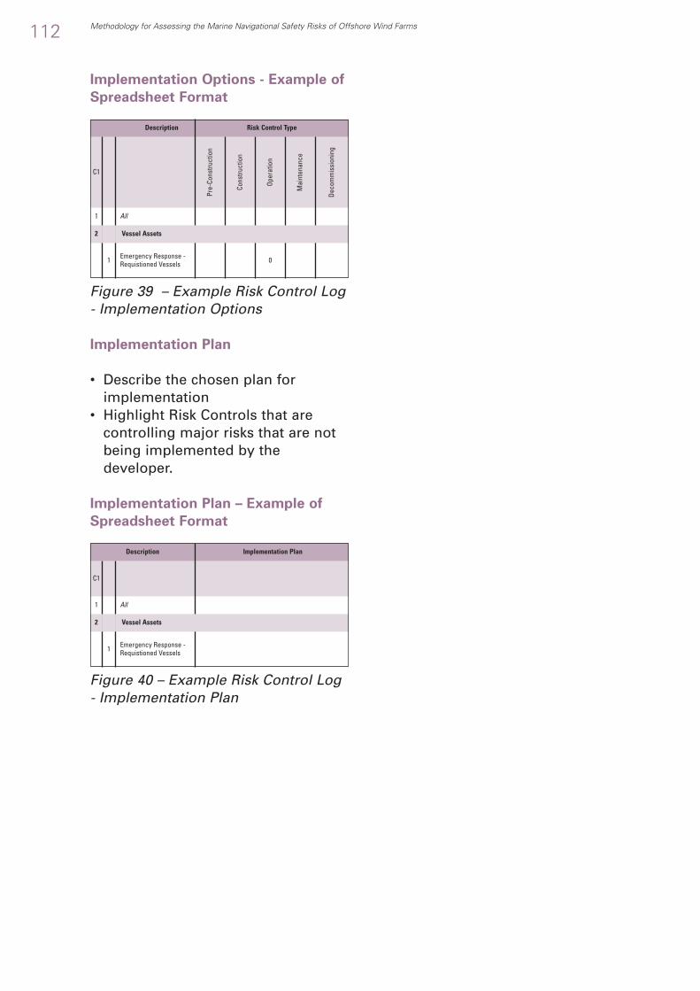
Implementation Options - Example of
Spreadsheet Format
Figure 39 – Example Risk Control Log - Implementation Options
Implementation Plan
• Describe the chosen plan forimplementation
• Highlight Risk Controls that arecontrolling major risks that are notbeing implemented by thedeveloper.
Implementation Plan – Example of
Spreadsheet Format
Figure 40 – Example Risk Control Log- Implementation Plan
112 Methodology for Assessing the Marine Navigational Safety Risks of Offshore Wind Farms
All
C1
1
Description Implementation Plan
1 Emergency Response -Requistioned Vessels
Vessel Assets2
All
C1
Pre-
Cons
truct
ion
Cons
truct
ion
Oper
atio
n
Mai
nten
ance
Deco
mm
issi
onin
g
1
Description Risk Control Type
01 Emergency Response -Requistioned Vessels
2 Vessel Assets

Where cost benefit assessments areused in support of ALARPjustifications the following may beused for comparative risk controloption selection.
E.2.1 Introduction
The FSA Guidelines require a processof Cost Benefit Assessment (CBA) torank proposed risk control options interms of risk benefit related to lifecycle costs. There is no unique wayof doing this but the following aresome of the techniques commonlyused in marine analysis.
• Cost per Unit Reduction in Risk(CURR)
• Gross Cost of Averting a Fatality(GCAF)
• Net Cost of Averting a Fatality(NCAF).
E.2.2 Cost per Unit Reduction ofRisk
Source: CURR was the measure usedin the UK Formal Safety Assessmentssubmissions to the IMO for HighSpeed Catamaran Ferries and BulkCarriers.
Cost per Unit Reduction of Risk(CURR) is an effective measure of thecost/benefit of a Risk Control Option.It is derived by calculating thedifference between the financial costsand financial benefits ofimplementing a Risk Control Optionand the predicted risk reductionachieved.
CURR can be calculated as:
Methodology for Assessing the Marine Navigational Safety Risks of Offshore Wind Farms 113
E.2. Guidance on Cost BenefitAssessment in Risk Control and MitigationSelection
Cost of the RCO - Savings in [environmental loss + property loss + business loss]
Change in Potential Loss of Life (PLL)
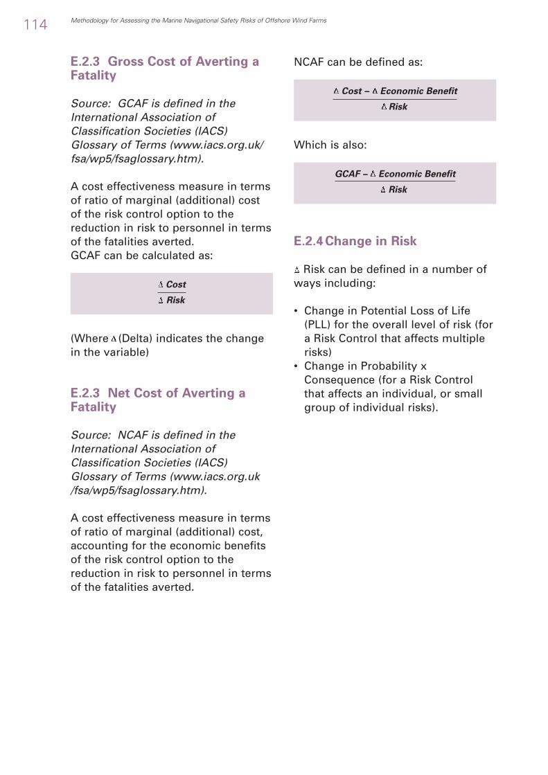
E.2.3 Gross Cost of Averting aFatality
Source: GCAF is defined in theInternational Association ofClassification Societies (IACS)Glossary of Terms (www.iacs.org.uk/fsa/wp5/fsaglossary.htm).
A cost effectiveness measure in termsof ratio of marginal (additional) costof the risk control option to thereduction in risk to personnel in termsof the fatalities averted.GCAF can be calculated as:
(Where (Delta) indicates the changein the variable)
E.2.3 Net Cost of Averting aFatality
Source: NCAF is defined in theInternational Association ofClassification Societies (IACS)Glossary of Terms (www.iacs.org.uk/fsa/wp5/fsaglossary.htm).
A cost effectiveness measure in termsof ratio of marginal (additional) cost,accounting for the economic benefitsof the risk control option to thereduction in risk to personnel in termsof the fatalities averted.
NCAF can be defined as:
Which is also:
E.2.4 Change in Risk
Risk can be defined in a number ofways including:
• Change in Potential Loss of Life(PLL) for the overall level of risk (fora Risk Control that affects multiplerisks)
• Change in Probability xConsequence (for a Risk Controlthat affects an individual, or smallgroup of individual risks).
114 Methodology for Assessing the Marine Navigational Safety Risks of Offshore Wind Farms
Cost
Risk
Cost – Economic Benefit
Risk
GCAF – Economic Benefit
Risk

Human Stakeholders
MarinersSailorsFishermenCrewPassengersGeneral Public
Navigation Stakeholders
Commercial shippingFishingRecreational MarinersPort AuthoritiesOffshore Oil and Gas IndustryMinistry of Defence
Navigation Support Stakeholders
Search and Rescue ServicesSalvorsMaritime and Coastguard Agency
Wind Farm Stakeholders
DeveloperOwner
E.3.1 Stakeholders Types
There are a variety of types ofStakeholder:
• Risk Imposer is whose actions orpolicies result in risk and needaction
• Risk Taker is whose action orinaction results in a risk
• Risk Beneficiary benefits fromimposing or taking the risk
• Risk Payer pays for themanagement of the risk
• Risk Sufferer suffers theconsequence of a risk
• Risk Observer is aware of the riskbut it does not affect them directly.
E.3.2 Stakeholders Types –Example Checklist
Methodology for Assessing the Marine Navigational Safety Risks of Offshore Wind Farms 115
E.3. Guidance on Assessing the Equity ofRisk Controls and Mitigations toStakeholders
1
1.11.21.31.41.51.62
2.12.22.32.42.52.63
3.13.23.34
4.14.2
●
●
●
●
●
●
●
●
●
●
●
●
●
●
●
●
●
●
●
●
●
Stakeholders
Imp
ose
r
Take
r
Bene
ficia
ry
Pay
er
Su
ffer
er
Ob
serv
er

116 Methodology for Assessing the Marine Navigational Safety Risks of Offshore Wind Farms
OperatorConstructionMaintainersInstallers
Wind Farm Insurance Stakeholders
Turbine InsurersWarranty InsurersLiability Insurers
Society Stakeholders
Shore PopulationsGeneral Population
Shipping Stakeholders
Owner, Operator or ManagerMasterCrewCrew AgencyTrade UnionsFamilies
Shipping Insurance Stakeholders
Hull UnderwritersCargo UnderwritersP & I Clubs
Ship Operations Stakeholders
Cargo OwnersChartererTerminal OperatorsStevedores
Shipbuilding Stakeholders
Designers, Ship-builders & RepairersEquipment MakersCommercial Services (e.g. ship chandlery)
Regulatory Stakeholders
International Maritime OrganisationFlag StateCoast StateInternational Association of Lighthouse AuthoritiesGeneral Lighthouse AuthorityMaritime and Coastguard Agency
Other Stakeholders
Professional BodiesTraining EstablishmentsLegal ServicesMarine ConsultantsMediaEnvironment and Pressure Groups
4.34.44.54.65
5.15.25.36
6.16.27
7.17.27.37.47.57.68
8.18.28.39
9.19.29.39.410
10.110.210.311
11.111.211.311.411.511.612
12.112.212.312.412.512.6
●
●
●
●
●
●
●
●
●
●
●
●
●
●
●
●
●
●
●
●
●
●
●
●
●
●
●
●
●
●
●
●
●
●
●
●
●
●
●
Stakeholders
Imp
ose
r
Take
r
Bene
ficia
ry
Pay
er
Su
ffer
er
Ob
serv
er
Table 29 – Example of StakeholderTypes

E.3.3 OrganisationsRepresenting Stakeholders
Stakeholders are represented byStakeholder Organisations who takedifferent roles including:
• Proposers who are proposing thedevelopment
• Approvers who are responsible forgiving a development its consent
• Advisors who are formallyconsulted by the approvers
• Commentators who are not formallyconsulted by the approvers but whomay provide input to them
• Observers.
E.3.4 OrganisationsRepresenting Stakeholders –Example Checklist
Methodology for Assessing the Marine Navigational Safety Risks of Offshore Wind Farms 117
Table 30 – Example of OrganisationsRepresenting Stakeholders
Association of British InsuranceBanksBritish Ports AssociationBWEA (including developers)CEFAS or SEAFISHChamber of ShippingThe Crown EstateDEFRADeveloperDeveloper's Legal TeamsDFTDTIMCAMoDNational Federation of Fishermen's OrganisationsNautical Institute Royal Institute of NavigationRepresentatives of Other CountriesRepresentatives of UK RegionsRepresentatives of three strategic areasRNLIRoyal Yachting AssociationTrinity HouseUK Harbour Masters AssociationUK Hydrographic OfficeUK Major Ports Group UK Offshore Aggregate Dredging AssociationUKOOA
●
●
●
●
●
●
●
●
●
●
●
●
●
●
●
●
●
●
●
●
●
●
●
●
●
●
●
●
Stakeholders Organisations
Pro
po
sers
Ap
pro
vers
Ad
viso
rs
Com
men
tato
rs
Ob
serv
ers

F.1.1 Background to the conceptof Claims and ReasonedArguments
The concept of a claim supported by areasoned argument is a developmentof the new technique used inreliability risk management.
F.1.2 Purpose of the Claim
The purpose of the Claim andReasoned Argument is to:
• Make a clear statement that isunderstandable to an informed, butnon risk specialist, reader what therisks are and what is being done tomake them broadlyacceptable/tolerable i.e.:
• To avoid specialist riskterminology
• To avoid implicit risk or risktolerability information beingburied in the text of a riskassessment
• Through the discipline of producinga clear concise statement make surethat the producer of the submissionhas convinced themselves that therisks have been identified, assessedin a thorough way, controlsdeveloped and the risks broadlyacceptable in a way that wouldstand up in “the court of informedopinion” if presented to a “judge”and challenged by “the defence”.
F.1.3 Developing the Claim
Developers should build upassessments and modelling to make areasoned argument for a positiveconsent decision based on a claimthat the risks are broadly acceptableor tolerable with further controls.
The reasoned argument is central to amarine navigational safety riskassessment. It is “a reasoned,auditable argument created tosupport the contention that a definedwind farm satisfies the requirements”.
The reasoned argument, togetherwith the supporting evidence, shouldbe written in a structured wayforming a logical flowing argumentthat can be read as a “mini story”.
It should link the requirements andassumptions to the evidence, thescience, the environment and theoperations to produce a reliabilityclaim. This is shown in conceptbelow:
118 Methodology for Assessing the Marine Navigational Safety Risks of Offshore Wind Farms
F.1. Guidance on Tolerability of Risk ClaimsSupported by a Reasoned Argument
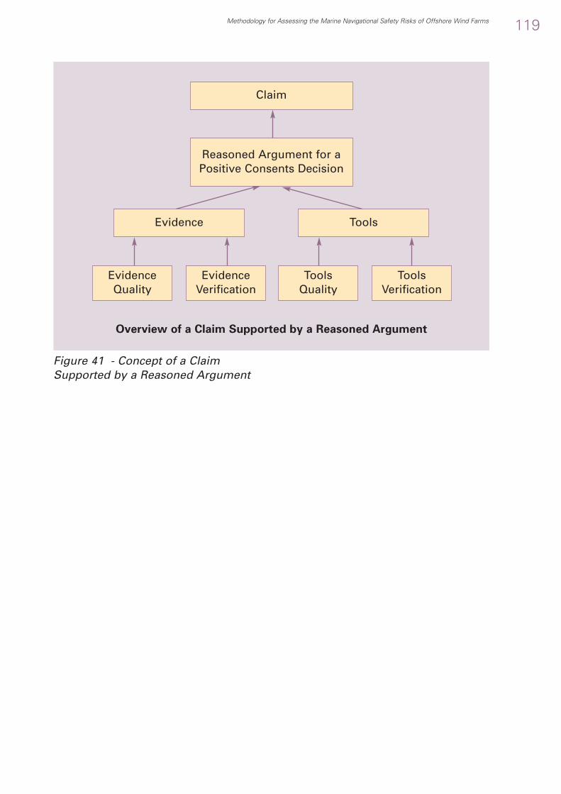
Figure 41 - Concept of a ClaimSupported by a Reasoned Argument
Methodology for Assessing the Marine Navigational Safety Risks of Offshore Wind Farms 119
Claim
Overview of a Claim Supported by a Reasoned Argument
Reasoned Argument for aPositive Consents Decision
ToolsEvidence
EvidenceQuality
EvidenceVerification
ToolsQuality
ToolsVerification

G.1. Example Hazard IdentificationChecklist
Description
Ref Description of Casual Chain (Event Sequence) (Accident Sequence)
General Navigation SafetyCollisionVessel navigating near a wind farm collides with another vessel that is navigating near a wind farmVessel navigating near a wind farm collides with another vessel navigating around a wind farm.Vessel navigating around a wind farm collides with another vessel that is navigating around a wind farm.Vessel navigating around a wind farm collides with another vessel that is navigating through a wind farm.Vessel navigating through a wind farm collides with another vessel that is navigating through a wind farm.Fishing vessel collides with another navigating vessel navigating near, around or through a wind farmPresence of fishing vessels causes collision between other navigating vessels.Recreational vessel collides with another navigating vessel navigating near, around or through a wind farmPresence of recreational vessels causes collision between other navigating vessels.Anchored vessel collides with another navigating vessel navigating near, around or through a wind farmPresence of anchored vessels causes collision between other navigating vessels.Vessel engaged in operations collides with another navigating vessel navigating near, around or through a wind farmPresence of vessels engaged in operations causes collision between other navigating vessels.Vessels engaged in servicing a wind turbine (e.g. a mother and daughter vessel arrangement) collide with each otherVessels engaged in servicing a wind turbine (e.g. a mother and daughter vessel arrangement) collide with anothernavigating vessel navigating near, around or through a wind farmPresence of vessels engaged in servicing a wind turbine (e.g. a mother and daughter vessel arrangement) causescollision with other navigating vesselsVessel engaged in a special event collides with another navigating vessel navigating near, around or through awind farmPresence of vessels engaged in a special event causes collision between other vessels.ContactVessel under control makes contact with a wind turbineVessel servicing a wind turbine makes contact with a wind turbine. (Special case of 3.01a)Vessel not under command makes contact with a wind turbineDrifting vessel makes contact with a wind turbine.Vessel under control makes contact with an offshore sub-stationVessel not under command makes contact with an offshore sub-stationDrifting vessel makes contact with an offshore sub-station.Vessel under control makes contact with an offshore service baseVessel not under command makes contact with an offshore service baseDrifting vessel makes contact with an offshore service baseVessel under control makes contact with an offshore accommodation platformVessel not under command makes contact with an offshore accommodation platformDrifting vessel makes contact with an offshore accommodation platformVessel under control makes contact with a wind turbine blade.Vessel servicing a wind turbine makes contact with a wind turbine blade. (Special case of 3.02a)Vessel not under command makes contact with a wind turbine bladeDrifting vessel makes contact with a wind turbine blade (Special case of above)Vessel under control makes contact with a fixed structure associated with a wind farm (e.g. transformer platform)Vessel servicing a wind farm makes contact with a fixed structure associated with a wind farmVessel not under command makes contact with a fixed structure associated with a wind farmDrifting vessel makes contact with a fixed structure associated with a wind farm (Special case of above)Grounding and StrandingVessel under control grounds or becomes stranded on a foundation structure and/or anti scour material.Vessel servicing a wind turbine grounds on a foundation structure and/or anti scour material. (Special case of the above)Vessel under control grounds or becomes stranded on a collapsed wind turbine
120 Methodology for Assessing the Marine Navigational Safety Risks of Offshore Wind Farms
1
1
111111111111
11
1
1
1
11
1111111111111111111111
11
1
2
222222222222
22
2
2
2
23
3333333333333333333338
88
8
010101010102020303040405
0506
06
06
07
07
010101010202020303030404040505060607070707
0101
02
abcdeabababa
ba
b
c
a
b
abcdabcabcabcabababab
ab

Description
Ref Description of Casual Chain (Event Sequence) (Accident Sequence)
Methodology for Assessing the Marine Navigational Safety Risks of Offshore Wind Farms 121
Vessel not under command grounds or becomes stranded on a foundation structure and/or anti scour materialDrifting vessel grounds or becomes stranded on a foundation structure and/or anti scour material (Special case of the above)Due to restricted manoeuvring a vessel navigating near a wind farm grounds or becomes stranded.Due to restricted manoeuvring a vessel navigating around a wind farm grounds or becomes stranded.Due to restricted manoeuvring a vessel navigating through a wind farm grounds or becomes stranded.Due to naturally shifting sand banks a vessel navigating near a wind farm grounds or becomes stranded.Due to naturally shifting sand banks a vessel navigating around a wind farm grounds or becomes stranded.Due to naturally shifting sand banks a vessel navigating through a wind farm grounds or becomes stranded.Due to the effect of scour a vessel navigating near a wind farm grounds or becomes stranded.Due to the effect of scour a vessel navigating around a wind farm grounds or becomes stranded.Due to the effect of scour a vessel navigating through a wind farm grounds or becomes stranded.Other Navigation SafetyFoundering and CapsizingSubsea obstacle snags fishing equipment heeling vessel and causing it to founder or capsize.Subsea cable snags fishing equipment heeling vessel and causing it to founder or capsize.Subsea fallen over turbine snags fishing equipment heeling vessel and causing it to founder or capsizeSubsea obstacle snags anchor heeling vessel and causing it to founder or capsize.Subsea cable snags anchor heeling vessel and causing it to founder or capsize.Subsea fallen over turbine snags anchor heeling vessel and causing it to founder or capsize.FireWind turbine fire requires emergency rescue of servicing staffWind turbine fire requires repair of burnt out turbine (and therefore deployment of support vessels) which mayaffect routing of vessels and the establishment of a wider safety zoneRelease of fire suppression (real or spurious triggers) releases inert gases into the air intakes of supportinghelicoptersNo reasonably foreseeable accident has been identified where a wind farm can cause a fire on a vessel (or viceversa) other than a consequence of a collision, contact, grounding or a strandingExplosionLeaking gas (e.g. from an underground gas field or from batteries) builds up in tower and explodes resulting inabandoned remains of a wind turbine and increased risk of contactNo other reasonably foreseeable cause of a wind turbine explosion has been identified other than by terrorismwhich is excluded from Formal Safety Assessment.No reasonably foreseeable accident has been identified where a wind farm can cause an explosion on a vesselother than as a consequence of a collision, contact, grounding or a stranding.Loss of Hull IntegrityNo reasonably foreseeable accident has been identified where a wind farm can cause a loss of hull integrity on avessel (or vice versa) other than as a consequence of a collision, contact, grounding or a stranding.FloodingNo reasonably foreseeable accident has been identified where a wind farm can cause flooding on a vessel (or viceversa) other than as a consequence of a collision, contact, grounding or a stranding.Machinery Related AccidentsWind turbine machinery accident requires emergency rescue of servicing staff.Blade failure results in the blade (or parts of the blade) hitting a navigating vessel or a person on the vesselIce on blade comes off hitting a navigating vessel or a person on the vesselDropped object from a maintenance or installation operation hits a navigating vessel or a person on the vesselBlade failure results in a floating blade entering the seawaysTurbine control failure results in a failure of turbine navigation aids (e.g. lighting) resulting in non detection of windfarm and increase risk of powered contactNo reasonably foreseeable accident has been identified where a wind farm can cause a machinery relatedaccident on a vessel (or vice versa) other than as a consequence of a collision, contact, grounding or a stranding.Payload Related AccidentsNo reasonably foreseeable accident has been identified where a wind farm can cause a machinery relatedaccident on a vessel other than as a consequence of a collision, contact, grounding or a stranding.Hazardous Substance AccidentNo reasonably foreseeable accident has been identified where a wind farm can cause a machinery relatedaccident on a vessel other than as a consequence of a collision, contact, grounding or a stranding.Accidents to personnelAccidents caused by Transfer to/from servicing vessel (or helicopter) to a wind turbineAccidents caused by Transfer between servicing vessels Accidents within the turbine requiring rescue of personnel. Toxic fume build up in the turbine from electrical fluids or batteries (or asphyxiation from fire suppression) requiringrescue of personnel. Person in water (unaided, in floatation device, life raft or life boat) requires rescue Bad weather (or other event) preventing egress from a wind turbine resulting in marooning and requiring rescue.Accidents to the General Public
ab
abcabc
abcabc
0303
040506070707080808
010101020202
0102
03
04
01
02
03
01
01
010203040506
07
01
01
01020304
0506
88
888888888
1
1111114
44
4
4
5
5
5
5
6
6
7
7
10
101010101010
10
11
11
12
12
1313131313
131314
11
1111111112
2
2222222
22
2
2
2
2
2
2
2
2
2
2
2
222222
2
2
2
2
2
22222
222

122 Methodology for Assessing the Marine Navigational Safety Risks of Offshore Wind Farms
Description
Ref Description of Casual Chain (Event Sequence) (Accident Sequence)
22
2
2223
3
334
4
44444
444
4
4
5
5
5
5
5
5
5
5
5
5
5
5
56
6
6
66
66
6
6
66
6
6
6
66
1414
16
161616
17
1717
20
2020202021
212121
22
22
30
30
31
31
32
32
33
33
34
35
35
35
30
30
3031
3132
32
33
3334
34
34
35
3535
0102
010203
0102
01020304
010203
01
01
01
01
01
01
01
01
02
01
01
01
01
02
0102
Wind farm causes vessel with hazardous substance on board to be routed closer to areas of habitation.No reasonably foreseeable accident has been identified where a wind farm can cause an accident to the generalpublic other than as a consequence of a collision, contact, grounding or a stranding.ElectrocutionVessel hits turbine structure sufficiently hard to pierce J tube and breach cable insulationAnchoring vessel drags up export cable and shorts cable to the anchorServicing (or SAR) helicopter operations case an electric discharge between the helicopter and the wind turbineAviation SafetyAviation AccidentsHelicopter flying to a turbine, sub-station, service base or accommodation base hits blades or tower and crashesHelicopter flying to a nearby installation or in transit hits blades or tower and crashesOther SafetyHigh Probability EventsContact between a service vessel and a wind turbine when transferring personnelInjury of service personnel when transferring to/from a wind turbineMan overboard of service personnel when transferring to/from a wind turbineNavigation in potential safety zonesHigh Severity OutcomesA major incident with a large Cruise Vessel or Passenger Ferry leading to a major search and rescue eventEmergency response operations following a major incident with a large oil tanker leading to large scale pollutionEmergency response operations following a major incident with a Liquefied Gas Tanker close to a major centre ofpopulation resulting in a large scale explosion riskLow Confidence/High UncertaintyNo risks have been identified where there is significant uncertainty in the assessment, the probability or of the outcomeSearch and RescueOverallPresence of the wind farm increases the risk of an accident (e.g. collision, contact, stranding or grounding) andalso inhibits search and rescue.External to InternalPerson or vessel requiring search and rescue drifts into a wind farm and the presence of wind farm inhibits searchand rescue.Internal to InternalActivities within a wind farm both generate an increased need for search and rescue and the presence of the windfarm inhibits search and rescue.Internal to ExternalActivities within a wind farm generate an increased need for search and rescue in the areas surrounding the wind farmExternal to ExternalPerson or vessel requiring search and rescue drifts through a wind farm and the presence of wind farm inhibitssearch and rescue during the transit stage.Worst CaseSearch and Rescue operations following a major incident with a large Cruise Vessel or Passenger FerryEmergency ResponseOverallPresence of wind farm increases need for emergency response from Foundering, Capsizing, Collision, Grounding or Stranding.Presence of wind farm inhibits ability to provide emergency response.External to InternalPollution outside wind farm drifts into wind farm and presence of wind farm inhibits clean upInternal to InternalActivities within a wind farm both generate an increased risk of pollution and the presence of the wind farm inhibitsclean up.Internal to ExternalActivities within a wind farm generate an increased risk of pollution in the areas surrounding the wind farm.External to ExternalPollution from outside a wind farm drifts through a wind farm and the presence of wind farm inhibits clean upduring the transit stage.Routing of vessels (or post collision, contact or grounded vessel) results in hazardous cargoes closer to areas of populationWorst CaseEmergency response operations following a major incident with a large oil tankerEmergency response operations following a major incident with a Liquefied Gas Tanker close to a major centre ofpopulation
Table 31 - Example Hazard Identification Checklist

Methodology for Assessing the Marine Navigational Safety Risks of Offshore Wind Farms 123
●
●
●
●
●
●
●
●
●
●
●
●
●
●
●
●
●
●
●
●
●
●
●
●
●
●
●
●
●
●
●
●
●
●
●
●
●
●
●
●
●
●
●
●
●
●
●
●
●
●
●
●
●
●
●
●
Description Risk Control Type Risk Control Effect
Ass
et
Ru
le
Go
od
Pra
ctic
e
Op
tio
n
Pre
ven
tio
n
Mit
igat
ion
●
●
●
●
●
●
●
●
●
Em
erg
ency
Res
po
nse
G.2 Example Risk Control Checklist
C1
1 All2 Vessel Assets
1 Emergency Response - Requisitioned Vessels2 Search and Rescue - Inshore3 Search and Rescue - Lifeboats4 Search and Rescue Requisitioned Vessels5 Tugs6 GLA Tenders7 Wind Farm Support Vessels
3 Aviation Assets
1 Search and Rescue - Helicopter2 Oil Spill Dispersant - Aircraft
4 Wind Farm Assets
1 AIS Base Station on / depicting wind farm2 VTS Radar on wind farm3 Marks and Lights4 Sound Signals5 CCTV
5 Wind Farm Control Room Assets
1 AIS monitoring6 Coast State Shore-based Assets
1 Marine Radar, Navigation and Communications Systems2 Marine Rescue Coordination Centres3 Vessel Traffic Service4 Shore Radar5 Lighthouses
7 Coast State Marine Assets
1 Buoys2 Marks and Lights3 External Assets4 GPS and Galileo
8 Other Assets
1 Pilot Services2 Charts
1 Consent
1 Deny consent to the wind farm2 Configuration and Design
1 Optimise location, alignment, size and layout2 Minimum safe (air) clearances [MGN 275 (M) Annex 1 Para 2]
3 Site Designation
1 Designation of the site as an area to be avoided (ATBA) [MGN275 (M)]
2 Safety zones of appropriate configuration, extent and applicationto specified vessels [MGN 275 (M)]
3 Marine traffic safety zone.4 Routeing and Routeing Management
1 Implementation of routeing measures within or near thedevelopment [MGN 275 (M)]
2a Manage traffic through VTS from Wind Farm Control Centre2b Manage traffic through VTS from MCA Control Centre3a Alert traffic via AIS tracking in Wind Farm Control Centre

124 Methodology for Assessing the Marine Navigational Safety Risks of Offshore Wind Farms
●
●
●
●
●
●
●
●
●
●
●
●
●
●
●
●
●
●
●
●
●
●
●
●
●
●
●
●
●
●
●
●
●
●
●
●
●
●
●
●
●
●
●
●
●
●
●
●
●
●
●
●
●
●
●
●
●
●
●
●
●
●
●
●
●
●
C1
Description Risk Control Type Risk Control Effect
Ass
et
Ru
le
Go
od
Pra
ctic
e
Op
tio
n
Pre
ven
tio
n
Mit
igat
ion
●
Em
erg
ency
Res
po
nse
Table 32 - Example Risk ControlChecklist
3b Alert traffic via AIS tracking in MCA Control Centre4a Continuous watch by multi-channel VHF, including Digital Selective
Calling (DSC) from Wind Farm Control Centre [MGN 275 (M)]4b Continuous watch by multi-channel VHF, including Digital
Selective Calling (DSC) from MCA control centre [MGN 275 (M)]5a Monitoring by radar, AIS and/or closed circuit television (CCTV)
from wind farm Control Centre [MGN 275 (M)]5b Monitoring by radar, AIS and/or closed circuit television (CCTV)
from MCA Control Centre [MGN 275 (M)]6 Remote radar (and AIS) sensing by pilot for remote pilotage7 Appropriate means to notify and provide evidence of the
infringement of ATBA’s, or safety zones [MGN 275 (M)]8 Speed limits to control wash9 VHF broadcast messages by transiting ships
5 Marking
1 External Marking of Offshore wind farms[GLA Requirements. Based on IALA Recommendation O-117 OnThe Marking of Offshore wind farms Edition 2]
2 Internal Marking of Offshore wind farms3 Marking of Individual Structures
[MGN 275 Annex 4 Section 1.1]4 Marking of Groups of Structures (Wind Farm)5 Other navigational aids
6 Communication and Training
1 Promulgation of information and warnings through notices tomariners and other appropriate media. [MGN 275 (M)] MCAwebsite “Navigation Safety” info.
2 Marking on Navigation Charts3 Adding wind farm navigation training to mariner training
syllabuses7 Removing need for Navigation
1 Turbine integrity reducing need for maintenance.2 Strength of foundation design.
8 Safety Management
1 Operator’s Safety Management System2 Operators Safety and Operations Plan3 Operators Emergency Plan4 Local and National Emergency Plans 5 Contingency plan if GPS switched off/failed6 Active Safety Management System (MGN 275 Annex 4)
9 Regulatory
1 Application of the principles of the Port Marine Safety Code towind farms
2 Mandatory switching on of AIS in and around wind farms3 Mandatory fishing boat tracking systems switched on in and
around wind farms4 Mandatory leisure craft “AIS” switched on in and around wind
farms10 Search and Rescue
1 SAR response planning.2 SAR asset provision planning.3 Turbine mast design (e.g. including safe refuge).
Standards and procedures for wind turbine generator shutdown[MGN 275 (M) Annex 4]
11 Emergency Planning
1 Salvage response planning.2 Salvage asset provision planning.3 Oil Spill response planning4 Oil Spill asset provision planning

Methodology for Assessing the Marine Navigational Safety Risks of Offshore Wind Farms 125
G.3 Example of MCA Wind FarmApplication Check Off List for MGN 275Compliance
Yes No Remarks
It is suggested that developersprepare, as part of their submission, aself-declaration against the MCA’sMGN 275 checklist.
In considering an application the MCAwill check to ensure that all aspects ofMGN 275 have been considered, andaddressed or discounted, wherenecessary or appropriate. This check
off list assures such compliance.Applicants that fail to demonstratecompliance with MGN 275, ordiscount inapplicable elements, riskprejudicing the timely considerationof their applications since it may thenbe necessary to seek amplifyinginformation to substantiate argumentsor assumptions.
MGN 275 Reference
Annex 1 - Considerations on Site Position, Structures and Safety Zones1 Traffic Survey
All vessel typesfour weeks duration, within 12 months prior to submission of the Environmental StatementSeasonal variationsRecreational and fishing vessel organisationsPort and navigation authorities
a. Proposed OREI site relative to areas used by any type of marine craft.b. Numbers, types and sizes of vessels presently using such areasc. Non-transit uses of the areas, e.g. fishing, day cruising of leisure craft, racing, aggregate
dredging, etc.d. Whether these areas contain transit routes used by coastal or deep-draught vessels on
passage.e. Alignment and proximity of the site relative to adjacent shipping lanesf. Whether the nearby area contains prescribed routeing schemes or precautionary areasg. Whether the site lies on or near a prescribed or conventionally accepted separation zone
between two opposing routesh. Proximity of the site to areas used for anchorage, safe haven, port approaches and pilot
boarding or landing areas.i. Whether the site lies within the limits of jurisdiction of a port and/or navigation authority.j. Proximity of the site to existing fishing grounds, or to routes used by fishing vessels to such
grounds.k. Proximity of the site to offshore firing/bombing ranges and areas used for any marine military
purposes.l. Proximity of the site to existing or proposed offshore oil / gas platform, marine aggregate
dredging, marine archaeological sites or wrecks, or other exploration/exploitation sitesm. Proximity of the site relative to any designated areas for the disposal of dredging spoiln. Proximity of the site to aids to navigation and/or Vessel Traffic Services (VTS) in or adjacent
to the area and any impact thereon.o. Researched opinion using computer simulation techniques with respect to the displacement
of traffic and, in particular, the creation of ‘choke points’ in areas of high traffic density.

126 Methodology for Assessing the Marine Navigational Safety Risks of Offshore Wind Farms
MGN 275 Reference Yes No Remarks
2 OREI Structuresa. Whether any features of the OREI, including auxiliary platforms outside the main generator
site and cabling to the shore, could pose any type of difficulty or danger to vessels underway,performing normal operations, or anchoring
• Clearances of wind turbine blades above the sea surface not less than 22 metres• Least depth of current turbine blades• The burial depth of cabling
b. Whether any feature of the installation could create problems for emergency rescueservices, including the use of lifeboats, helicopters and emergency towing vessels (ETVs)
c. How rotor blade rotation and power transmission, etc., will be controlled by the designatedservices when this is required in an emergency.
3 Assessment of Access to and Navigation Within, or Close to, an OREITo determine the extent to which navigation would be feasible within the OREI site itself byassessing whether:a. Navigation within the site would be safe:
i. by all vessels, orii. by specified vessel types, operations and/or sizes.iii. in all directions or areas, oriv. in specified directions or areas.v. in specified tidal, weather or other conditions
b. Navigation in and/or near the site should be:i. prohibited by specified vessels types, operations and/or sizes.ii. prohibited in respect of specific activities,iii. prohibited in all areas or directions, oriv. prohibited in specified areas or directions, orv. prohibited in specified tidal or weather conditions, or simplyvi. recommended to be avoided.
c. Exclusion from the site could cause navigational, safety or routeing problems for vesselsoperating in the area.
Note: Relevant information concerning a decision to seek a “safety zone” for a particular siteduring any point in its construction, operation or decommissioning must be presented. Annex 2 - Navigation, collision avoidance and communications
1 The Effect of Tides and Tidal Streams : It should be determined whether or not:
i. Current maritime traffic flows and operations in the general area are affected by thedepth of water in which the proposed installation is situated at various states of the tide i.e. whether the installation could pose problems at high water which do notexist at low water conditions, and vice versa.
ii. Set and rate of the tidal stream, at any state of the tide, has a significant affect onvessels in the area of the OREI site.
iii. Maximum rate tidal stream runs parallel to the major axis of the proposed sitelayout, and, if so, its effect.
iv. The set is across the major axis of the layout at any time, and, if so, at what rate.v. In general, whether engine failure or other circumstance could cause vessels to be
set into danger by the tidal stream.vi. Structures themselves could cause changes in the set and rate of the tidal stream.vii. Structures in the tidal stream could be such as to produce siltation, deposition of
sediment or scouring, affecting navigable water depths in the wind farm area oradjacent to the area
Note: A hydrographic survey of the site and its immediate environs has been undertaken to establish a baseline. Such a survey should be undertaken to at least International Hydrographic Organization(IHO) Order 1 standard multibeam bathymetry, with final data being supplied as a digital full densitydata set, and erroneous soundings flagged as deleted but included in the data set.
2 Weather:To determine if:
i. The site, in normal, bad weather, or restricted visibility conditions, could presentdifficulties or dangers to craft, including sailing vessels, which might pass in closeproximity to it.
ii The structures could create problems in the area for vessels under sail, such aswind masking, turbulence or sheer.
3 Visual Navigation and Collision Avoidance:To assess the extent to which:
i. Structures could block or hinder the view of other vessels under way on any route.ii. Structures could block or hinder the view of the coastline or of any other
navigational feature such as aids to navigation, landmarks, promontories, etc

Methodology for Assessing the Marine Navigational Safety Risks of Offshore Wind Farms 127
MGN 275 Reference Yes No Remarks
4 Communications, Radar and Positioning Systems:To provide researched opinion of a generic and, where appropriate, site specific nature concerning whether or not
i. Structures could produce radio interference such as shadowing, reflections or phasechanges, with respect to any frequencies used for marine positioning, navigation orcommunications, including Automatic Identification Systems (AIS), whether ship borne,ashore or fitted to any of the proposed structures.
ii. Structures could produce radar reflections, blind spots, shadow areas or other adverseeffects:a. Vessel to vesselb. Vessel to shore;c. VTS radar to vessel;d. Racon to/from vessel.
iii. OREI, in general, would comply with current recommendations concerningelectromagnetic interference.
iv. Structures and generators might produce sonar interference affecting fishing, industrialor military systems used in the area.
v. Site might produce acoustic noise which could mask prescribed sound signals.vi. Generators and the seabed cabling within the site and onshore might produce electro-
magnetic fields affecting compasses and other navigation systems.5 Marine Navigational Marking:
To determine:i. How the overall site would be marked by day and by night taking into account that there
may be an ongoing requirement for marking on completion of decommissioning,depending on individual circumstances.
ii. How individual structures on the perimeter of and within the site, both above and belowthe sea surface, would be marked by day and by night.
iii. If the site would be marked by one or more racons and/ or,iv. If the site would be marked by an Automatic Identification System (AIS) transceiver, and
if so, the data it would transmit.v. If the site would be fitted with a sound signal, and where the signal or signals would be
sitedvi. Whether the proposed site and/or its individual generators would comply in general with
markings for such structures, as required by the relevant General Lighthouse Authority(GLA) or recommended by the Maritime and Coastguard Agency, respectively.
vii. The aids to navigation specified by the GLAs are being maintained such that the‘availability criteria’, as laid down and applied by the GLAs, is met at all times. Separatedetailed guidance is available from the GLAs on this matter.
viii. The procedures that need to be put in place to respond to casualties to the aids tonavigation specified by the GLAs, within the timescales laid down and specified by theGLAs.
Annex 3 - Safety and mitigation measures recommended for OREI during construction, operationand decommissioning.Mitigation and safety measures will be applied to the OREI development appropriate to the leveland type of risk determined during the Environmental Impact Assessment (EIA). The specificmeasures to be employed will be selected in consultation with the Maritime and CoastguardAgency and will be listed in the developer’s Environmental Statement (ES). These will beconsistent with international standards contained in, for example, the Safety of Life at Sea(SOLAS) Convention - Chapter V, IMO Resolution A.572 (14)3 and Resolution A.671(16)4 and couldinclude any or all of the following:
i. Promulgation of information and warnings through notices to mariners and otherappropriate media.
ii. Continuous watch by multi-channel VHF, including Digital Selective Calling (DSC).iii. Safety zones of appropriate configuration, extent and application to specified vesselsiv Designation of the site as an area to be avoided (ATBA).v. Implementation of routeing measures within or near to the development.vi. Monitoring by radar, AIS and/or closed circuit television (CCTV).vii. Appropriate means to notify and provide evidence of the infringement of safety zones or
ATBA’s.viii. Any other measures and procedures considered appropriate in consultation with other
stakeholders.Annex 4 - Standards and procedures for wind turbine generator shutdown in the event of asearch and rescue, counter pollution or salvage incident in or around a wind farm
1 Design RequirementsThe wind farm should be designed and constructed to satisfy the following design requirementsfor emergency rotor shut-down in the event of a search and rescue (SAR), counter pollution orsalvage operation in or around a wind farm:
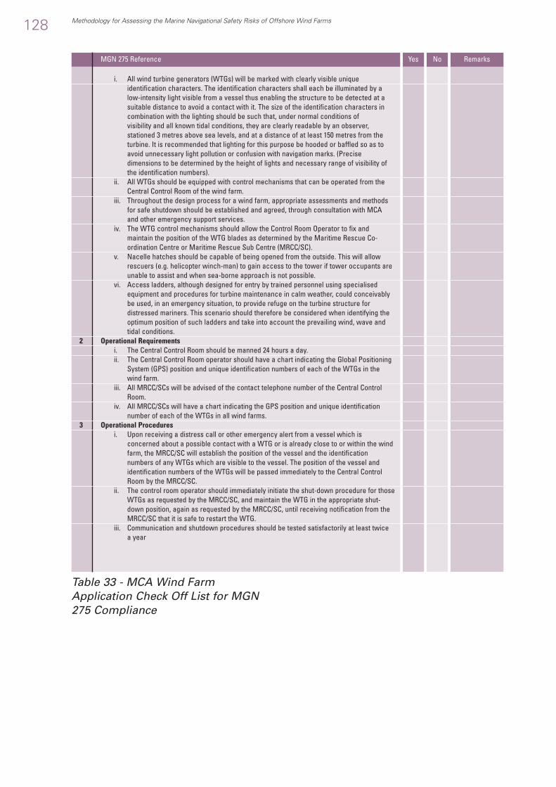
128 Methodology for Assessing the Marine Navigational Safety Risks of Offshore Wind Farms
MGN 275 Reference Yes No Remarks
i. All wind turbine generators (WTGs) will be marked with clearly visible uniqueidentification characters. The identification characters shall each be illuminated by alow-intensity light visible from a vessel thus enabling the structure to be detected at asuitable distance to avoid a contact with it. The size of the identification characters incombination with the lighting should be such that, under normal conditions of visibility and all known tidal conditions, they are clearly readable by an observer,stationed 3 metres above sea levels, and at a distance of at least 150 metres from theturbine. It is recommended that lighting for this purpose be hooded or baffled so as toavoid unnecessary light pollution or confusion with navigation marks. (Precisedimensions to be determined by the height of lights and necessary range of visibility ofthe identification numbers).
ii. All WTGs should be equipped with control mechanisms that can be operated from theCentral Control Room of the wind farm.
iii. Throughout the design process for a wind farm, appropriate assessments and methodsfor safe shutdown should be established and agreed, through consultation with MCAand other emergency support services.
iv. The WTG control mechanisms should allow the Control Room Operator to fix andmaintain the position of the WTG blades as determined by the Maritime Rescue Co-ordination Centre or Maritime Rescue Sub Centre (MRCC/SC).
v. Nacelle hatches should be capable of being opened from the outside. This will allowrescuers (e.g. helicopter winch-man) to gain access to the tower if tower occupants areunable to assist and when sea-borne approach is not possible.
vi. Access ladders, although designed for entry by trained personnel using specialisedequipment and procedures for turbine maintenance in calm weather, could conceivablybe used, in an emergency situation, to provide refuge on the turbine structure fordistressed mariners. This scenario should therefore be considered when identifying theoptimum position of such ladders and take into account the prevailing wind, wave andtidal conditions.
2 Operational Requirementsi. The Central Control Room should be manned 24 hours a day.ii. The Central Control Room operator should have a chart indicating the Global Positioning
System (GPS) position and unique identification numbers of each of the WTGs in thewind farm.
iii. All MRCC/SCs will be advised of the contact telephone number of the Central ControlRoom.
iv. All MRCC/SCs will have a chart indicating the GPS position and unique identificationnumber of each of the WTGs in all wind farms.
3 Operational Proceduresi. Upon receiving a distress call or other emergency alert from a vessel which is
concerned about a possible contact with a WTG or is already close to or within the windfarm, the MRCC/SC will establish the position of the vessel and the identificationnumbers of any WTGs which are visible to the vessel. The position of the vessel andidentification numbers of the WTGs will be passed immediately to the Central ControlRoom by the MRCC/SC.
ii. The control room operator should immediately initiate the shut-down procedure for thoseWTGs as requested by the MRCC/SC, and maintain the WTG in the appropriate shut-down position, again as requested by the MRCC/SC, until receiving notification from theMRCC/SC that it is safe to restart the WTG.
iii. Communication and shutdown procedures should be tested satisfactorily at least twice a year
Table 33 - MCA Wind FarmApplication Check Off List for MGN275 Compliance

Table 34 - Marine Accident Categories
H.1.1 Marine Accident Categories
Methodology for Assessing the Marine Navigational Safety Risks of Offshore Wind Farms 129
H1 Terms, Abbreviations & References
Description
1 Foundering To sink below the surface of the water.2 Collision Collision is defined as a vessel striking, or being struck, by another vessel, regardless of whether
either vessel is under way, anchored or moored; but excludes hitting underwater wrecks.3 Contact Contact is defined as a vessel striking, or being struck, by an external object that is not
another vessel or the sea bottom.Sometimes referred to as Impact
4 Fire Fire is defined as the uncontrolled process of combustion characterised by heat or smoke orflame or any combination of these.
5 Explosion An explosion is defined as an uncontrolled release of energy which causes a pressurediscontinuity or blast wave.
6 Loss of Hull Integrity Loss of Hull Integrity (LOHI) is defined as the consequence of certain initiating events thatresult in damage to the external hull, or to internal structure and sub-division, such that anycompartment or space within the hull is opened to the sea or to any other compartment orspace.
7 Flooding Flooding is defined as sea water, or water ballast, entering a space, from which it should beexcluded, in such a quantity that there is a possibility of loss of stability leading to capsizing orsinking of the vessel.
8 Grounding Grounding is defined as the ship coming to rest on, or riding across underwater features orobjects, but where the vessel can be freed from the obstruction by lightening and/orassistance from another vessel (e.g. tug) or by floating off on the next tide.
9 Stranding Stranding is defined as being a greater hazard than grounding and is defined as the shipbecoming fixed on an underwater feature or object such that the vessel cannot readily bemoved by lightening, floating off or with assistance from other vessels (e.g. tugs).
10 Machinery Related Accidents Machinery related accidents are defined as any failure of equipment, plant and associatedsystems which prevents, or could prevent if circumstances dictate, the ship from manoeuvringor being propelled or controlling its stability.
11 Payload Related Accidents Payload related accidents include loss of stability due to cargo shifting and damage to thevessel’s structure resulting from the method employed for loading or discharging the cargo.This category does not include incidents which can be categorised as Hazardous Substance,Fires, Explosions, Loss of Hull Integrity, Flooding accidents etc.
12 Hazardous Substance Accidents Hazardous substance accidents are defined as any substance which, if generated as a resultof a fire, accidental release, human error, failure of process equipment, loss of containment,or overheating of electrical equipment; can cause impairment of the health and/or functioningof people or damage to the vessel. These materials may be toxic or flammable gases,vapours, liquids, dusts or solid substances.
13 Accidents to Personnel Accidents to personnel are defined as those accidents which cause harm to any person onboard the vessel e.g. crew, passengers, stevedores; which do not arise as a result of one ofthe other accident categories. Essentially, it refers to accidents to individuals, though thisdoes not preclude multiple human casualties as a result of the same hazard, and typicallyincludes harm caused by the movement of the vessel when underway, slips, trips, falls,electrocution and confined space accidents, food poisoning incidents, etc.
14 Accidents to the General Public Accidents to personnel are defined as those accidents which lead to injury, death or loss ofproperty amongst the population ashore resulting from one of the other ship accidentcategories.41
15 Capsizing The overturning of a vessel after attaining negative stability
Category
41 This definition is interpreted from MGN 275 rather that a generally recognised marine accident category.

130 Methodology for Assessing the Marine Navigational Safety Risks of Offshore Wind Farms
H.1.2 Risk Terms used in this Methodology
Definition
Accident An unintended event involving fatality or injury, property loss or damage orenvironmental damage.
Accident Category A designation of accident reported according to their nature.Consequence The outcome of an accident.FN Curve The cumulative frequency (F) of an accident versus the number (N) of fatalities.Formal Safety Assessment A rational and systematic process for assessing the risk associated with an activity
and for evaluating the costs and benefits of options for reducing these risks.Frequency The number of occurrences per unit time (e.g. per year).Hazard A potential to threaten human life, health, property of the environment.Individual Risk A direct measure of the frequency of fatalities for individuals.Initiating Event The first in a sequence of events leading to a hazardous situation or accident.Risk The combination of the frequency of occurrence and the severity of the consequence.Risk Control Measure A means of controlling a single element of risk.Risk Control Option A grouping of risk control measures into a practical regulatory option.Societal Risk An indirect measure of the magnitude of the event taking into account public
aversion to large accidents.
Term
H.1.3 Abbreviations used in this Methodology
Full Name
AIS Automatic Identification SystemBMT British Maritime TechnologyCBA Cost Benefit AnalysisCEFAS Centre for Environment, Fisheries and Aquaculture ScienceCPA Coast Protection Act 1949CURR Cost per Unit Reduction of RiskDEFRA Department for Environment, Food & Rural AffairsDFT Department for Transport (in the UK)DTI Department of Trade and Industry (in the UK)DTLR Department of Transport, Local Government and the RegionsER Emergency ResponseETA Event Tree AnalysisEU European UnionFEPA Food and Environmental Protection Act 1985FMEA Failure Modes and Effects AnalysisFSA Formal Safety AssessmentFTA Fault Tree AnalysisGCAF Gross Cost of Averting a FatalityHAZOP Hazard and Operability StudiesHSE Health and Safety ExecutiveIMO International Maritime OrganisationLOHI Loss of Hull IntegrityMCA Maritime and Coastguard AgencyMGN Marine Guidance NoteMRCC Maritime Rescue Co-ordination CentreMRSC Maritime Rescue Sub CentreMSN Merchant Shipping NoticeNCAF Net Cost of Averting a FatalityNCP National Contingency PlanOSIS Oil Spill Information SystemPLL Potential Loss of LifeRAF Royal Air Force RCM Risk Control MeasureRCO Risk Control OptionRNLI Royal National Lifeboat InstitutionRPPP HSE Document Reducing Risks, Protecting PeopleRZPZ HSE Document Reducing Risks, Protecting PeopleSAR Search and RescueSARIS Search and Rescue Information SystemSRMD Search and Rescue Methodology DatabaseVTS Vessel Traffic System
Table 35 - Risk Terms used in this Methodology
Table 36 - Abbreviations Used in this Methodology

Methodology for Assessing the Marine Navigational Safety Risks of Offshore Wind Farms 131
1 Project FRCA/005/000/12P “Methodology for Assessing the Marine Navigational Safety Risks ofOffshore Wind Farms. DTI 29th November 2005
2 MGN 275: Marine Guidance Note 275(M) “Proposed UK Offshore Renewable EnergyInstallations (OREI) – Guidance on Navigational Safety Issues.” Maritime and CoastguardAgency, August 2004. This is available from http://www.mcga.gov.uk/in the “Guidance andRegulations” section.
3 Reducing Risks Protecting People (RRPP or R2P2), ISBN 0 7176 2151 0, available as a downloadfrom www.hse.gov.uk/risk/theory/r2p2.htm
8 Merchant Shipping Notice 1781 (M + F) “The Merchant Shipping (Distress Signals andPrevention of Collisions Regulations) 1996” The Maritime and Coastguard Agency, May 2004.This is available from www.mcga.gov.uk in the “Guidance and Regulations” section.
11 Merchant Shipping Notice MSN 1781 (M + F) The Merchant Shipping (Distress Signals andPrevention of Collisions) Regulations 1996. (From www. mcga.gov.uk, Guidance andRegulations, Merchant Shipping Notices)
31 ISO 9000:2000 TickIT GuideVarious “Results of the electromagnetic investigations and assessments of marine radar,
communications and positioning systems undertaken at the North Hoyle wind farm by QinetiQand the Maritime and Coastguard Agency” MCA website: www.mcga.gov.uk, hence SafetyInformation / Navigation Safety, OREI.
H.1.4 References
TitleRef
Table 37 –Some References used inthis Methodology

Formal Safety Assessment (FSA) Notes
The following information is taken fromthe data posted on the Maritime andCoastguard Agency’s web site by itsRisk, Analysis and Prevention Branch.The full documents can be obtained byaccessing www.mcga.gov.uk, thence“Safety Information” and “FSA” Thesections that follow have been selectedas appropriate for offshore wind farmuse.
About the FSA
Formal Safety Assessment is astructured, systematic five-stepmethodology, aimed at enhancingmaritime safety including theprotection of life, health, the marineenvironment and property using riskanalysis, cost benefit analysis andregulatory influence diagrams tofacilitate decision making.
The FSA Methodology
132 Methodology for Assessing the Marine Navigational Safety Risks of Offshore Wind Farms
Appendix A
Decision makersIdentify problem, initiate FSA, receiverecommendations, decide, implement
Step 1Identify hazards
Step 2Analyse risk
Step 3Generate risk
control options
Step 5 Recommendationsto decision makers
Step 4 Cost benefit
anaysis

FSA evaluates not only that aparticular measure will improvemaritime safety or pollutionprevention but also by how much andat what cost. FSA also ensures thatsafety measures are equitable byidentifying who carries the risk, whobenefits from the reduction in risk andwho bears the cost.
FSA comprises of five steps, asfollows:
• Identification of hazards. • Assessment of the risks associated
with those hazards. • Consideration of alternative ways of
managing those risks. • Cost benefit assessment of
alternative risk managementoptions.
• Decisions on which option to select.
Objectives
The objective of this paper is tooutline a systematic and robustmethodology for Step 2 of FSA, i.e.for assessing the risks arising fromthe hazards to which vessels areexposed. The methodology is genericin character, encompassing andevaluating in a consistent way risksarising from different sources andallows their relative significance to beassessed. It is important to be able totrace these various sources of risk totheir more fundamental underlyingcauses such that appropriateregulations can be found.The work carried out within theFormal Safety Assessment Branch canbe applied to all aspects of the MCAand maritime industry andenvironmental issues to facilitateachieving the organisations’ keytargets and business activities.
Representation of Uncertainty inStep 2 Methodology
Background
Uncertainty is inherent in all riskassessment. It is important to assessthe magnitude of the uncertainty toensure that the input of the resultsinto cost benefit analysis is realistic.This section describes how the areasof uncertainty arise in Step 2 inrelation to:
• Uncertainty in the estimation ofbase case risk levels;
• Uncertainty in quantification of riskreduction measures; and
• The effects of uncertainty on theresults.
• Additionally, a method forrepresenting uncertainty in theresults is given.
Uncertainty in Estimation of Base
Case Risk Levels
The base case risk is quantified fromhistorical data. This allows someconfidence that the predicted risklevels are reasonable, and that theygive an accurate indication of theareas of high risk. It is thusconsidered that there is likely to beless uncertainty associated with thismethodology at this stage than withother possible methodologies.However there remains a number ofareas of uncertainty in the analysis,such as:
• The applicability of historical data tothe current situation; and
• Uncertainty in the completeness ofthe data
Methodology for Assessing the Marine Navigational Safety Risks of Offshore Wind Farms 133

The applicability of historical data to
the current situation
Over a period of time there are likelyto be changes to the risks associatedwith a system. This might be due toolder equipment being replaced bymodern items, degradation of existingequipment and structures, changes inmanagement systems, changes inoperating conditions etc. These willtend to move the actual risk levelsaway from the average historicallevels, so that the present-day risk isdifferent from the risk used as a basisfor calculation. The net result is oftena lowering of the risk over a period oftime.
However such changes are usuallyvery slow to occur and often have aminimal impact on accident statisticsover, say, a ten year period. In theshipping industry in particular there isunlikely to be a sudden step-changein overall risk levels as vessels arelikely to trade for over 20 years andpractices evolve rather than beingreplaced by entirely novel methods. Itis thus expected that this will have asmall impact on the uncertaintyinherent in the analysis.
Uncertainty in the completeness of
the data
It is extremely unlikely that everyaccident will be reported. This willlead to an historical risk level that islower than the risk in reality. This isexpected to be the major cause ofuncertainty in the estimation of thebase case risk levels. The shippingindustry is very diverse, and there isno central body to which all accidentsmust be reported.
However, there are a number oforganisations that collect shippingaccident data and it is very likely thatmajor accidents, particularly thoseinvolving loss of life, or majorpollution will be known by thoseorganisations. It is thus expected that,whilst there will be some uncertaintyin the results, the high-risk areas willhave been adequately identified.
Uncertainty in Quantification of Risk
Reduction Measures
The results of the assessment of riskreduction measures will be subject tosome uncertainty. The key areas ofthe analysis where uncertainty isexpected to be the greatest are:
• The quantification of the effects ofhuman factors;
• The use of engineering judgement;and
• The necessity for simplifyingassumptions.
Risk reduction measures areevaluated by considering the changein factors that influence themagnitude, progression and initiatingof an event. These factors arequantified in terms of their changefrom the average level, and hence ifno change from the average isexpected then no change to the risk ismodelled. The exclusion of a factorfrom consideration thus implies thatan average level is assumed. Hencethe omission of possible influences onrisk is likely to have a much smallereffect on the results than with othermethodologies.
134 Methodology for Assessing the Marine Navigational Safety Risks of Offshore Wind Farms

The Effects of Uncertainty on the
Results
Each item of data will have an upperand lower band of uncertaintyassociated with it. The combinedeffects of all the uncertainties are toplace a range on the results. Theinputs to the risk assessment can bevaried, and error bands can be put onthe results, between which it isexpected that the risk lie. Thus, theoverall FN curve will have three lineson it:
• The maximum likely risk level; • A best estimate of the risk; and • The minimum likely risk level.
It is unlikely that all estimates willover-predict the risk, and it is equallyunlikely that all will under-predict therisk. Indeed, some will over-predictand some will under-predict, with theerrors partially counterbalancing eachother and leading to results which area cautious best estimate of risk.
It is therefore sensible to vary a fewkey assumptions, or items of data, inorder to examine which are the mostimportant. The item that mostincreases the risk, should be varied toits maximum limit to obtain themaximum likely risk level, andsimilarly the item which mostdecreases the risk should be varied toits minimum limit to obtain theminimum likely risk level.
When passing on results to othersteps in the methodology, it isimportant that the uncertainty boundsare passed also, along withinformation on the key areas ofuncertainty and what effect theymight have on the risk levels.
Calculational Requirements
The application of the Step 2methodology does not require anyspecialised software, although someof the many available fault treeanalysis packages may prove useful inassisting the development of theprogression trees. However, incommon with the majority of currentrisk assessment methods, there wouldneed to be a heavy reliance on theuse of spreadsheets with overallstructures, or macros, pre-programmed within them.
All the calculations involved in theprocess are relatively simplemultiplication/division andaddition/subtraction, however thereare potentially a very large number ofthese to perform. In addition there is aneed to “tag” different influences sothat their effect on the completepicture, or only parts of it, can beaccurately represented. So, forexample the effect of improvedtraining regimes on the overall riskcould be assessed whether this maybe on the initiation of an event, itsprogression, or the severity of theaccident in terms of loss of life.Similarly, the relative contributions tothese various areas of risk could beassessed and the principalintermediate causes or actionsquantified. For example does theeffect of training on improvinginspection and housekeeping,produce a bigger risk reduction thanimproved fire-fighting or improvedevacuation of passengers? What arethe key assumptions/influences indriving these results? How sensitiveare they to the assumptions, and wasthere a great divergence of opinion atthe group session that set the value ofthe influences?
Methodology for Assessing the Marine Navigational Safety Risks of Offshore Wind Farms 135

The spreadsheet structure would needto be devised as a result of thestructuring of the risk contributiontree, the influence diagrams and theprogression and magnitude trees,with the calculationalinterdependencies defined. Not allroutes through the structure would ofcourse be used for all events ofinterest, some would be unused byhaving null values. This spreadsheetwould need to be developed by anexperienced risk analyst with amathematical bias, and wouldinevitably be refined as the processprogressed.
Options for Step 2
Background to Development
A number of options can beconsidered in the application of theStep 2 FSA methodology. These are,amongst others:
• Hazard based risk assessment • Hazard and operability (HAZOP)
studies • Failure modes and effects analysis
(FMEA) • Issues analysis • Risk profile generation. • Each of these options is considered
in turn below.
Hazard Based Risk Assessment
This is the ‘traditional’ approach torisk assessment, and is based uponthe following sequence of activities:Define the system being studied. Identify the hazards associated withthat system.
• Assess the likelihood of the hazardsoccurring.
• Identify how each hazard mightprogress to various outcomes.
• Assess the likelihood of progressionto each outcome.
• Assess the consequencesassociated with each outcome.
• Multiply likelihood andconsequence to obtain the riskassociated with each outcome.
Sum the risks associated with theoutcomes to produce an overall risk
This is a very robust and systematicapproach, and has been used formany years to assess risks in a largenumber of diverse industries,including the shipping industry. Inaddition, these eight steps listedabove could be said to comprise ageneric methodology for assessingrisks and, as such, warrantsconsideration as an approach for theapplication of a FSA methodology.The above approach has severaladvantages, namely:
• It is a generic technique; • It is very thorough; • It easily leads to the identification of
incident progression pathways; • It attempts to recreate reality (i.e.
hazards lead to accidents, which inturn have consequences).
The main disadvantage to thisapproach is that, although thesequence of steps is generic for allrisk assessments, the analysis doesnot lead to a generic answer. This isdue to the necessity to rigorouslydefine the system being studied inorder to identify the hazardsassociated with that system. Althoughsuch an approach is ideal whenconsidering a specific vessel, the
136 Methodology for Assessing the Marine Navigational Safety Risks of Offshore Wind Farms

shipping industry is by nature a verydiverse industry. Even so-called‘sister’ ships often vary in ways thatsignificantly affect the way in which itis operated or in the way that ahazard might progress to cause anaccident. Thus, for this approach to beable to produce a realistic estimate ofthe risk to an entire class of vessels, avery large number of separatearrangements of hardware (engines,bulkheads, fuel systems, fireextinguishing systems, etc) andsoftware (procedures) must beevaluated. Attempts to evaluate theoverall risk levels by defining a‘typical’ vessel will at best lead to apoor estimation of overall risks, andat worst divert attention from the realissues and lead to a net risk increase.
In addition, there are several otherareas of difficulty and complexityassociated with this approach:
• Often insufficient data exists on thelikelihood of failures and on thepotential for those failures toescalate e.g. the likelihood of a fuelleak in an engine room igniting orthe proportion of steering gearfailures that lead to a collision).
• All mitigating measures must beconsidered explicitly in order toexamine the progress of the event.
• It is difficult for future updates tothe analysis to incorporate novelrisk reduction measures or changesto the system description. Typically,a large proportion of the analysismust be re-worked.
The approach is not easy to audit.Many fault trees and/or event treesare generally required to perform theanalysis, and these are difficult tocheck.
HAZOP Studies
A HAZOP study is a genericmethodology for formally identifyingthe hazards associated with a system.It can be combined with a riskassessment exercise (either rankingby experts or by more rigorousquantification) in order to assess therisk associated with that system.
A HAZOP study relies on several keyitems:
• A rigorously defined system tostudy;
• The use of appropriate keywordsand guide-words;
• An experienced HAZOP team withcomplementary areas of knowledge.
As with the hazard-based riskassessment technique, this approachis generic and systematic. It has alsobeen used for several years in manyindustries, and has proven its worthfor hazard identification and, whencombined with risk ranking, for simplerisk assessment.
In order to utilise this technique for FSA purposes it is necessary to:
• Define appropriate keywords andguidewords;
• Define an appropriate level of riskassessment.
The lack of the above definition doesnot detract from the potentialusefulness of this tool. Theadvantages of this approach are thatit is:
• A generic technique; • Very thorough;
Methodology for Assessing the Marine Navigational Safety Risks of Offshore Wind Farms 137

• A visible process (i.e. it is possibleto identify exactly which eventshave been considered);
• Requires little knowledge of riskassessment techniques.
However, as previously discussed,techniques that rely on a veryrigorous definition of the systembeing studied have several inherentdisadvantages. In addition, otherdisadvantages are that:
• It does not lead easily to an explicitquantification of overall risk;
• The team members are limited bytheir personal experience;
• It is difficult to update the analysisover time;
FMEA
The FMEA technique is very similar toa HAZOP study, in that a definedsystem is considered in some detail,following a formalised procedure.Faults at the part/component level areidentified and, using failure rates forthe appropriate operating conditions,their effect on the system level isdetermined. Each part is considered inturn as having failed in each possiblemode. The effect of each of thesefailures at various system levels isnoted and a failure rate assigned fromavailable data. Each system levelfailure mode will be seen to resultfrom various possible componentfailures, and these can be groupedtogether for the purpose of calculatingthe system failure rate. Again, thisapproach is generic and systematic,and is a widely accepted technique forassessing the reliability of a system.The advantages to this approach arethat it:
• Is a generic technique; • Is very thorough; • Easily leads to the identification of
incident progression pathways.
Again, however, a detailed systemdefinition is required. It suffers fromthe same disadvantages as thehazard-based approach. In addition itdoes not quantify the effects offailures, and so further work isrequired in order to estimate risklevels.
Issues Analysis
Issue analysis is a systematicapproach to ensure that all key issuesare identified with a lower chance ofoversight. There are four tasks in theprocess:
• The first task requires that theoverall over-riding issue should beidentified.
• The second task breaks down the overall issue into issues andsub-issues in terms of simplestatements of requirements; thesemust have yes or no answers as towhether they are correct orcomplied with or “not confirmed”.
• The third task develops hypothesesfrom these sub-issues.
• The fourth task developsconclusions and recommendations.
This approach is very good foranalysing a non-numerical problem ina logical and systematic way. It doesnot rely on a detailed systemdescription, and can very quicklydevelop a logical basis from whichdecisions can be made or attentionfocused. The approach is highlyvisible, as a logical structure can bedrawn showing the relationshipbetween the issues and sub-issues,
138 Methodology for Assessing the Marine Navigational Safety Risks of Offshore Wind Farms

facilitating auditability. Thedisadvantage is that this method doesnot readily facilitate the analysing of anumerical problem, as the answersare all in terms of ‘Yes/No’.
Risk Profile Generation
This approach is generic methodologyfor determining the risk profile of atype of vessel, system or function andfor identifying the underlying causeswhich make up that risk profile. Thefirst task is to classify the variouscauses of accidents. This allows theclassification of risks into categories(e.g. ‘Collision’) and subcategories(eg. ‘Collision caused by watch-keeping failure’). Secondly, the riskprofile for a typical vessel of the typebeing considered is generated in theform of a logic tree structure, herecalled “the risk contribution tree”.This process performed from the topdown, as follows:
• The top-level risks are initiallyquantified (from historical data forestablished ship types).
• The second level risks are assignedby determining their contribution tothe top-level risks.
• Similarly, any third or further levelrisks are assigned by determiningtheir contribution to t he first levelrisks.
• This process is repeated until allrisks have been quantified.
Once the risk profile has beengenerated, the underlying causes ofthe bottom level risks are determined.These are evaluated separately forfactors that influence the frequency ofan event occurring, factors thatinfluence the progression of an eventto cause loss and factors thatinfluence the magnitude of the loss.
A logical structure is then developedshowing the relationship between thevarious factors. In the initial basecase, all the influencing factors are setat a value of 1.0, i.e. they neither raisenor lower the risk away from thehistorically observed value for anaverage vessel of that type. Once riskreduction measures are proposed,these factors are evaluated in terms oftheir influence on average risk levels,with a value of 1.2 indicating a 20%increase in the risk and a value of 0.8indicating a 20% reduction in the risk.
Approach Adopted in this Paper
It is this latter approach of risk profilegeneration that has been adopted asthe central methodology in this step.The risk profile process may beillustrated diagrammatically as a riskcontribution tree. The purpose of therisk contribution tree is to structurethe causes of accidents and apportionthe contribution they make to thefrequency of loss of life (as derivedfrom the F-N, frequency - number offatality curves).
The traditional approaches to riskassessment discussed above, andused in other industries are ideallysuited to situations where the largeaccidents are rare events that cannotbe reliably predicted, and where thereis a need to reflect precise differencesin design and operation of eachindividual plant or platform. In thecase of shipping, however, there is awealth of data on the major lossesthat have occurred and theirimmediate causes. The situation isdifferent therefore from that in whichQuantified Risk Assessment (QRA)techniques are normally used. Inaddition, the need in this case togenerate a generic methodology
Methodology for Assessing the Marine Navigational Safety Risks of Offshore Wind Farms 139

precludes the approach of otherindustries as this is necessarilytailored to specific installations oroperation by means of event treeswhich vary in structure.
The approach to apply is thereforeone in which the risk to a typicalvessel is determined (from historicaldata), and then broken down byvarious hazardous outcomes;multiplying factors (which may raiseor lower risk for those outcomes awayfrom the norm) are quantified.
The key elements of the methodologyare therefore that it will:
• Minimise the use of complex eventtrees;
• Concentrate on “high level” issuesand avoid the consideration of ship-specific aspects;
• Be modular, in order to allow futureimprovements to be slotted in ortaken out as appropriate;
• Be flexible, in order to incorporateresults and requirements from otherprojects running concurrently;
• Account for the possibility that riskreduction measures may raise somerisks whilst lowering others.
The identification of three categoriesof influencing factors is consistentwith the main components of risk,which are:
• Frequency • Consequence • Magnitude of impact.
Often consequence and impact arecombined and termed “severity”,however it is important to distinguishbetween them in the consideration ofrisk reduction. Clearly an accident canbe a serious event in terms of damage
to the ship without necessarilyaffecting the safety of people. At theextreme this may be because thereare no people present, however inpractice what is meant is the rapidremoval of people from the incidentor their effective protection from itseffects. Therefore in thismethodology, these threecomponents have been addressedseparately by using likelihood,progression, and magnitude factors.The quantification of the effect ofdifferent risk control options on thesefactors may be achieved in manydifferent ways, using one of severaltechniques. One particularly usefulmethod in this context however isthat of the influence diagramapproach which is a method ofmodelling the network of influences.These influences link failures at theoperational level with their directcauses, and with the underlyingorganisational and regulatoryinfluences.
Performance influencing factorsrepresent the effect of underlyingcauses by operating on the directcauses. In addition to providing aqualitative tool for understanding thenature of these influences, theinfluence diagram can also be used asa predictive tool. Although theinfluence diagram approach has beendeveloped in the context of humanfactors and failures it can also beapplied to accidents primarily due tohardware failures or external events(e.g. extreme weather). It is alsonecessary to consider other causalinfluences introduced through thestate of knowledge inherent in designapproaches, material selection,construction technology and theoperating environment to which shipsare subjected. This knowledge is
140 Methodology for Assessing the Marine Navigational Safety Risks of Offshore Wind Farms

embedded in rules and regulationsand supporting design, constructionand operational practice.
This largely top down analysis alsomake the best use of the relativelygood data available at the majoraccident level. This does not,however, imply that the methodologywill only address accidents that havehappened in a reactive way. Theessential feature of the methodologyis the generation of a generic riskprofile for a vessel type where thefactors that may affect this risk,whether in terms of likelihood,progression or magnitude of fatalities,are explicit and may be varied toreflect changes in operation, design orsafety measures aided by appropriateinfluence diagrams. By trying tounderstand the underlying causes,therefore, the method becomes aproactive tool rather than reactive.This top down approach has beensuccessfully used in a number ofother applications:
• In the railway industry to determinethe causes of fatalities at levelcrossings, and also to determine thenecessity for ATP (Automatic TrainProtection) systems.
• In the nuclear industry to determinethe likelihood of degraded coresfrom loss of coolant accidents.
• In the offshore industry in twoways; to evaluate events which cancause impairment of safetyfunctions in the Norwegian conceptsafety evaluation and, on aLiverpool Bay Oil storage barge tomodify tanker fire and explosiondata for the enhanced operationaland human factors situation.
Methodology for Assessing the Marine Navigational Safety Risks of Offshore Wind Farms 141

1 Introduction:
1.1 Offshore Renewable EnergyInstallations (OREI) include off s h o rewind farms, marine current turbines,wave generators and any otherinstallation, with the potential to affectmarine navigation and safety,proposed for United Kingdom (UK)
internal waters, territorial sea or in aRenewable Energy Zone (REZ), whenestablished, beyond the territorial sea.
1.2 Recommendations in thisguidance note should be taken intoaccount by OREI developers seekingformal consent for marine works.Failure by developers to give due
Proposed UK Offshore Renewable Energy Installations (OREI) -Guidance on Navigational Safety Issues.
Notice to Other UK Government Departments, Offshore Renewable Energy
Developers, Port Authorities, Shipowners, Masters, Ships’ Officers, Fishermen
and Recreational Sailors.
142 Methodology for Assessing the Marine Navigational Safety Risks of Offshore Wind Farms
Appendix B
Summary
This guidance note highlights issues that need to be taken into considerationwhen assessing the impact on navigational safety from offshore renewableenergy developments, proposed for United Kingdom internal waters,territorial sea or in a Renewable Energy Zone, when established, beyondthe territorial sea.
Key Points
• The recommendations in this guidance note should be used, primarily, byoffshore renewable energy installation developers, seeking consent toundertake marine works.
• Specific annexes address issues covering; site position, structures andsafety zones (Annex 1), developments, navigation, collision avoidance andcommunications (Annex 2), safety and mitigation measures recommendedfor OREI during construction, operation and decommissioning (Annex 3),search and rescue matters (Annex 4), Section 36 of the Electricity Act 1989,as amended by the Energy Act 2004 (Annex 5) and Article 60 of the UnitedNations Convention on the Law of the Sea (UNCLOS) (Annex 6).
MARINE GUIDANCE NOTEMGN 275 (M)

Methodology for Assessing the Marine Navigational Safety Risks of Offshore Wind Farms 143
regard to these recommendationsmay result in objections to theirproposals on the grounds ofnavigational safety. Additionalinformation on the process forconsenting off shore windfarms andthe regulatory framework is availablefrom the Offshore RenewablesConsents Unit of Department forTrade and Industry (DTI)1. It should benoted, however, that DTI is notresponsible for consenting projects inNorthern Ireland internal andterritorial waters.
1.3 The considerations and criteriacontained in the attached annexes areintended to address the navigationalimpact of OREI proposed for UK sites.Their development necessitates theestablishment of a clear consentsprocess to deal with potentialdetrimental effects. The consentregime must take account of localfactors, national standards andinternational aspects which couldinfluence the establishment of anOREI. Under the regime, consents willnot be granted if OREIs are likely tointerfere with the use of recognisedsea lanes essential to internationalnavigation.
1.4 The Energy Act 2004 establishes aregulatory regime for OREI beyondterritorial waters, in the UK’s REZ, andsupplements the regime whichalready applies in Great Britain’sinternal and territorial waters. Section99 of the Act deals specifically withnavigation and introduces a newsection, 36B with the title “duties inrelation to navigation” into section 36of the Electricity Act 1989. The text ofsection 36, as amended by theEnergy Act, is attached at Annex 5.Under 36B(1) a consent cannot begranted for an OREI which is likely to
interfere with the use of recognisedsea lanes essential to internationalnavigation. This term is married at36B(7) to Article 60(7) of the UnitedNations Convention on the Law ofthe Sea. The text of Article 60 isattached at Annex 6. 36B(2)consolidates into section 36 theprovisions of section 34 of the CoastProtection Act 1949
1.5 The recommendations have beendeveloped in consultation with DTI,the devolved government authoritiesfor Scotland, Wales and NorthernIreland, mariners in the commercial,military, fisheries and recreationalsectors, relevant associations and portauthority representatives, the GeneralLighthouse Authorities (GLA) andemergency support services such asthe Royal National Lifeboat Institution(RNLI).
2. How and when therecommendations should beused.
2.1 This Guidance Note, as the nameimplies, is intended for the guidanceof developers and others. Whilst nonmandatory, failure to heed theguidance may result in delaying theconsents process. Therecommendations should be takeninto account by OREI developers andtheir contracted environmental andrisk assessors in the preparation ofScoping Reports (SR), EnvironmentalImpact Assessments (EIA) andresulting Environmental Statements(ES).
2.2 These should evaluate allnavigational possibilities, which couldbe reasonably foreseeable, by whichthe siting, construction, establishment
1 www.dti.gov.uk/energy/leg_and_reg/consents/guidance.pdf

and decommissioning of an OREIcould cause or contribute to anobstruction of, or danger to,navigation or marine emergencyservices. They should also be used toassess the most favourable options tobe adopted.
2.3 Potential navigational orcommunications difficulties caused toany mariners or emergency servicesusing the site area and its environsshould be assessed. Those difficultieswhich could contribute to a marinecasualty leading to injury, death orloss of property, either at sea oramongst the population ashore,should be highlighted as well as thoseaffecting emergency services.Consultation with local and nationalsearch and rescue authorities shouldbe initiated and consideration given tothe types of vessels and equipmentwhich might be used in emergencies.This should include the possible useof OREI structures as emergencyrefuges.
2.4 Assessments should be made ofthe consequences of ships deviatingfrom normal routes or recreationalcraft entering shipping routes in orderto avoid proposed sites. Specialregard should be given to evaluatingsituations which could lead to safetyof navigation being compromised e.g.an increase in ‘end-on’ or ‘crossing’encounters, reduction in sea-room orwater depth for manoeuvring etc.
2.5 In terms of navigational priority,these recommendations do notencourage a differentiation to bemade between any types of seagoingwater craft, operations, or mariners.
3. Annexes:
3.1 The recommendations containedthere in apply to all sites, whetherwithin the jurisdiction of port limits orin open sea areas. However, portauthorities may require developers tocomply with their own specificcriteria. In addition, whereproposals within port limits couldaffect navigation or emergencyplanning, the port authorities will beunder an obligation to review itssafety management system, inaccordance with the Port MarineSafety Code. Such reviews should beundertaken in parallel with the OREIdeveloper’s Environmental ImpactAssessment and the outcomeaddressed in the resultingEnvironmental Statement.
3.2 OREI developers should complywith the recommendations during allphases of their planning, construction,operation and decommissioning.
3.3 Information concerning theirnavigational impact during these fourphases should be promulgated inample time to all relevant mariners,organisations and authorities.
3.4 Contingency arrangements todeal with marine casualties in, oradjacent to sites, including responsesto environmental pollution, should beplanned, and practised to test theirefficiency.
3.5 The following annexes containrecommendations on:
Annex 1: Considerations on siteposition and structure.
Annex 2: Navigation, collisionavoidance and communications.
144 Methodology for Assessing the Marine Navigational Safety Risks of Offshore Wind Farms

Annex 3: Safety and mitigationmeasures recommended for OREIduring construction, operation anddecommissioning.
Annex 4: S tandards and proceduresfor wind turbine generatorshutdown in the event of a search andrescue, counter pollution or salvageincident in or around a wind farm.
3.6 The following annexes containregulatory extracts:
Annex 5: Section 36 of the ElectricityAct 1989 (as amended by the EnergyAct 2004).
Annex 6: Article 60 of the UnitedNations Convention on the Law of theSea (UNCLOS), relating to artificialislands, installations and structures inthe exclusive economic zone.
3.7 Note: The Maritime andCoastguard Agency (MCA) reservesthe right to vary or modify theserecommendations on the basisof experience or in accordance withinternationally recognised standardsin the interest of safety of life at seaand protection of the marineenvironment. As other types ofoffshore renewable energyinstallations are developed, newannexes to this document will beintroduced and a revision of thisMarine Guidance Note will be issued.
Hydrography, Meteorology & PortsBranch Bay 2/30 Spring PlaceMaritime and Coastguard Agency105 Commercial RoadSouthampton SO15 1EG
Tel: 02380 329135Fax: 02380 329204
August 2004
File MNA53/10/0360
© Crown Copyright 2004
Safer Lives, Safer Ships, Cleaner Seas
Printed on material containing 100%post-consumer waste
Methodology for Assessing the Marine Navigational Safety Risks of Offshore Wind Farms 145

Annex 1. Considerations on SitePosition, Structures and SafetyZones
1. Traffic Survey
An up to date2 traffic survey of thearea concerned should be undertaken.This should include all vessel typesand is likely to total at least four weeksduration but also taking account ofseasonal variations in traffic patterns.These variations should bedetermined in consultation withrepresentative recreational and fishingvessel organisations, and, whereappropriate, port and navigationauthorities. Whilst recognising thatsite-specific factors need to be takeninto consideration, any such surveyshould, in general, assess:
a. Proposed OREI site relative toareas used by any type of marinecraft.
b. Numbers, types and sizes ofvessels presently using suchareas.
c. Non-transit uses of the areas, e.g.fishing, day cruising of leisurecraft, racing, aggregate dredging,etc.
d. Whether these areas containtransit routes used by coastal ordeep-draught vessels on passage.
e. Alignment and proximity of the siterelative to adjacent shipping lanes.
f. Whether the nearby area containsprescribed routeing schemes orprecautionary areas.
g. Whether the site lies on or near aprescribed or conventionallyaccepted separation zone betweentwo opposing routes.
h. Proximity of the site to areas usedfor anchorage, safe haven, portapproaches and pilot boarding orlanding areas.
i. Whether the site lies within thelimits of jurisdiction of a portand/or navigation authority.
j. Proximity of the site to existingfishing grounds, or to routes usedby fishing vessels to such grounds.
k. Proximity of the site to offshorefiring/bombing ranges and areasused for any marine militarypurposes.
l. Proximity of the site to existing orproposed offshore oil / gasplatform, marine aggregatedredging, marine archaeologicalsites or wrecks, or otherexploration/exploitation sites.
m. Proximity of the site relative toany designated areas for thedisposal of dredging spoil.
n. Proximity of the site to aids tonavigation and/or Vessel TrafficServices (VTS) in or adjacent tothe area and any impact thereon.
o. Researched opinion usingcomputer simulation techniqueswith respect to the displacementof traffic and, in particular, thecreation of ‘choke points’ in areasof high traffic density.
2. OREI Structures
It should be determined:
a. Whether any features of the OREI,including auxiliary platformsoutside the main generator site andcabling to the shore, could poseany type of difficulty or danger tovessels underway, performingnormal operations, or anchoring.
Such dangers would includeclearances of wind turbine bladesabove the sea surface, the leastdepth of current turbine blades,the burial depth of cabling, etc.
146 Methodology for Assessing the Marine Navigational Safety Risks of Offshore Wind Farms
2 Within 12 months prior to the submission of the Environmental Statement

Note: Recommended minimum safe(air) clearances between sea levelconditions at mean high water springs(MHWS) and wind turbine rotors arethat they should be suitable for thevessels types identified in the trafficsurvey but generally not less than 22metres. Depths, clearances and similarfeatures of other OREI types whichmight affect marine safety should bedetermined on a case by case basis.
b. Whether any feature of theinstallation could create problemsfor emergency rescue services,including the use of lifeboats,helicopters and emergencytowing vessels (ETVs)
c. How rotor blade rotation andpower transmission, etc., will becontrolled by the designatedservices when this is required inan emergency.
Note: Annex 4 of this documentdetails HM Coastguard recommendedstandards and procedures for the useof an Active Safety ManagementSystem (ASMS) in the event of anincident in or around an offshorewind farm.
3. Assessment of Access to andNavigation Within, or Close to,an OREI
To determine the extent to whichnavigation would be feasible withinthe OREI site itself byassessing whether:
a. Navigation within the site wouldbe safe :
i. by all vessels, orii. by specified vessel types,
operations and/or sizes.iii. in all directions or areas, or
iv. in specified directions or areas.v. in specified tidal, weather or other
conditions.b. Navigation in and/or near the site
should be :i. prohibited by specified vessels
types, operations and/or sizes.ii. ii. prohibited in respect of specific
activities,iii. prohibited in all areas or
directions, oriv. prohibited in specified areas or
directions, orv. prohibited in specified tidal or
weather conditions, or simplyvi. recommended to be avoided.c. Exclusion from the site could
cause navigational, safety orrouteing problems for vesselsoperating in the area.
Note : Relevant informationconcerning a decision to seek a“safety zone” for a particular siteduring any point in its construction,operation or decommissioning,should be promulgated to MCA andother interested parties without delay.
Annex 2. Navigation, collisionavoidance and communications
1. The Effect of Tides and TidalStreams:
It should be determined whether ornot:
i. Current maritime traffic flows andoperations in the general area areaffected by the depth of water inwhich the proposed installation issituated at various states of thetide i.e. whether the installationcould pose problems at highwater which do not exist at lowwater conditions, and vice versa.
Methodology for Assessing the Marine Navigational Safety Risks of Offshore Wind Farms 147

ii. Set and rate of the tidal stream, atany state of the tide, has asignificant affect on vessels in thearea of the OREI site.
iii. Maximum rate tidal stream runsparallel to the major axis of theproposed site layout, and, if so, itseffect.
iv. The set is across the major axis ofthe layout at any time, and, if so,at what rate.
v. In general, whether engine failureor other circumstance could causevessels to be set into danger bythe tidal stream.
vi. Structures themselves couldcause changes in the set and rateof the tidal stream.
vii. Structures in the tidal streamcould be such as to producesiltation, deposition of sedimentor scouring, affecting navigablewater depths in the windfarm areaor adjacent to the area.
Note: In relation to Sub Paragraph viiabove, it is considered necessary thata hydrographic survey of the site andits immediate environs be undertakento establish a baseline. Such a surveyshould be undertaken to at leastInternational HydrographicOrganization (IHO) Order 1 standardmultibeam bathymetry , with finaldata being supplied as a digital fulldensity data set, and erroneoussoundings flagged as deleted butincluded in the data set.
2. Weather:
To determine if:
i. The site, in normal, bad weather,or restricted visibility conditions,could present difficulties ordangers to craft, including sailing
vessels, which might pass in closeproximity to it.
ii. The structures could createproblems in the area for vesselsunder sail, such as wind masking,turbulence or sheer.
3. Visual Navigation andCollision Avoidance:
To assess the extent to which:
i. Structures could block or hinderthe view of other vessels underway on any route.
ii. Structures could block or hinderthe view of the coastline or of anyother navigational feature such asaids to navigation, landmarks,promontories, etc.
4. Communications, Radar andPositioning Systems:
To provide researched opinion of ageneric and, where appropriate, sitespecific nature concerning whether ornot:
i. Structures could produce radiointerference such as shadowing,reflections or phase changes, withrespect to any frequencies usedfor marine positioning, navigationor communications, includingAutomatic Identification Systems(AIS), whether ship borne, ashoreor fitted to any of the proposedstructures.
ii. Structures could produce radarreflections, blind spots, shadowareas or other adverse effects:
a. Vessel to vessel;b. Vessel to shore;c. VTS radar to vessel;d. Racon to/from vessel.
148 Methodology for Assessing the Marine Navigational Safety Risks of Offshore Wind Farms

iii. OREI, in general, would complywith current recommendationsconcerning electromagneticinterference.
iv. Structures and generators mightproduce sonar interferenceaffecting fishing, industrial ormilitary systems used in the area.
v. Site might produce acoustic noisewhich could mask prescribedsound signals.
vi. Generators and the seabedcabling within the site andonshore might produce electro-magnetic fields affectingcompasses and other navigationsystems.
5. Marine Navigational Marking:
To determine:
i. How the overall site would bemarked by day and by nighttaking into account that there maybe an ongoing requirement formarking on completion ofdecommissioning, depending onindividual circumstances.
ii. How individual structures on theperimeter of and within the site,both above and below the seasurface, would be marked by dayand by night.
iii. If the site would be marked byone or more racons and/ or,
iv. If the site would be marked by anAutomatic Identification System(AIS) transceiver, and if so, thedata it would transmit.
v. If the site would be fitted with asound signal, and where thesignal or signals would be sited.
vi. Whether the proposed site and/orits individual generators wouldcomply in general with markingsfor such structures, as required bythe relevant General Lighthouse
Authority (GLA) or recommendedby the Maritime and CoastguardAgency, respectively.
vii. The aids to navigation specifiedby the GLAs are being maintainedsuch that the ‘availability criteria’,as laid down and applied by theGLAs, is met at all times. Separatedetailed guidance is availablefrom the GLAs on this matter.
viii. The procedures that need to beput in place to respond tocasualties to the aids tonavigation specified by the GLAs,within the timescales laid downand specified by the GLAs.
Annex 3. Safety and mitigationmeasures recommended forOREI during construction,operation and decommissioning.
3.1 Mitigation and safety measureswill be applied to the OREIdevelopment appropriate to the leveland type of risk determined during theEnvironmental Impact Assessment(EIA).The specific measures to beemployed will be selected inconsultation with the Maritime andCoastguard Agency and will be listedin the developer’s EnvironmentalStatement (ES). These will beconsistent with international standardscontained in, for example, the Safetyof Life at Sea (SOLAS) Convention -Chapter V, IMO Resolution A.572 (14)3
and Resolution A.671(16)4 and couldinclude any or all of the following:
i. Promulgation of information andwarnings through notices tomariners and other appropriatemedia.
ii. Continuous watch by multi-channel VHF, including DigitalSelective Calling (DSC).
Methodology for Assessing the Marine Navigational Safety Risks of Offshore Wind Farms 149
3 “General Provisions on Ships’ Routeing”, adopted on 20 November 19854 “Safety Zones and Safety of Navigation around Offshore Installations and Structures”, adopted 19 October 1989.

iii. Safety zones of appropriateconfiguration, extent andapplication to specified vessels.
iv. Designation of the site as an areato be avoided (ATBA).
v. Implementation of routeingmeasures within or near to thedevelopment.
vi. Monitoring by radar, AIS and/orclosed circuit television (CCTV).
vii. Appropriate means to notify andprovide evidence of theinfringement of safety zones orATBA’s.
viii. Any other measures andprocedures consideredappropriate in consultation withother stakeholders.
Annex 4. Standards andprocedures for wind turbinegenerator shutdown in theevent of a search and rescue,counter pollution or salvageincident in or around a windfarm.
1. Design Requirements
The wind farm should be designedand constructed to satisfy thefollowing design requirements foremergency rotor shut-down in theevent of a search and rescue (SAR),counter pollution or salvage operationin or around a wind farm:
i. All wind turbine generators(WTGs) will be marked withclearly visible uniqueidentification characters. Theidentification characters shall eachbe illuminated by a low-intensitylight visible from a vessel thusenabling the structure to bedetected at a suitable distance toavoid a collision with it. The size
of the identification characters incombination with the lightingshould be such that, under normalconditions of visibility and allknown tidal conditions, they areclearly readable by an observer,stationed 3 metres above sealevels, and at a distance of at least150 metres from the turbine. It isrecommended that lighting forthis purpose be hooded or baffledso as to avoid unnecessary lightpollution or confusion withnavigation marks. (Precisedimensions to be determined bythe height of lights and necessaryrange of visibility of theidentification numbers).
ii. All WTGs should be equippedwith control mechanisms that canbe operated from the CentralControl Room of the wind farm.
iii. Throughout the design processfor a wind farm, appropriateassessments and methods forsafe shutdown should beestablished and agreed, throughconsultation with MCAand otheremergency support services.
iv. The WTG control mechanismsshould allow the Control RoomOperator to fix and maintain theposition of the WTG blades asdetermined by the MaritimeRescue Co-ordination Centre orMaritime Rescue Sub Centre(MRCC/SC).
v. Nacelle hatches should becapable of being opened from theoutside. This will allow rescuers(e.g. helicopter winch-man) togain access to the tower if toweroccupants are unable to assistand when sea-borne approach isnot possible.
vi. Access ladders, althoughdesigned for entry by trainedpersonnel using specialised
150 Methodology for Assessing the Marine Navigational Safety Risks of Offshore Wind Farms

equipment and procedures forturbine maintenance in calmweather, could conceivably beused, in an emergency situation,to provide refuge on the turbinestructure for distressed mariners.This scenario should therefore beconsidered when identifying theoptimum position of such laddersand take into account theprevailing wind, wave and tidalconditions.
2. Operational Requirements
i. The Central Control Room shouldbe manned 24 hours a day.
ii. The Central Control Roomoperator should have a chartindicating the Global PositioningSystem (GPS) position and uniqueidentification numbers of each ofthe WTGs in the wind farm.
iii. All MRCC/SCs will be advised ofthe contact telephone number ofthe Central Control Room.
iv. All MRCC/SCs will have a chartindicating the GPS position andunique identification number ofeach of the WTGs in all windfarms.
3. Operational Procedures
i. Upon receiving a distress call orother emergency alert from avessel which is concerned about apossible collision with a WTG oris already close to or within thewind farm, the MRCC/SC willestablish the position of thevessel and the identificationnumbers of any WTGs which arevisible to the vessel. The positionof the vessel and identificationnumbers of the WTGs will be
passed immediately to the CentralControl Room by the MRCC/SC.
ii. The control room operator shouldimmediately initiate the shut-down procedure for those WTGsas requested by the MRCC/SC,and maintain the WTG in theappropriate shut-down position,again as requested by theMRCC/SC, until receivingnotification from the MRCC/SCthat it is safe to restart the WTG.
iii. Communication and shutdownprocedures should be testedsatisfactorily at least twice a year
Note: Other types, designs andconfigurations of OREI will besimilarly evaluated and procedureslaid down by the Maritime andCoastguard Agency, in consultationwith appropriate stakeholders, duringthe Scoping and EnvironmentalImpact Assessment processes.
Annex 5. Section 36 of theElectricity Act 1989 (as amendedby the Energy Act 2004)
36 Consent required for construction
etc of generating stations
(1) Subject to subsections (2) and (4)below, a generating station shallnot be constructed at a relevantplace (within the meaning ofsection 4), and a generatingstation at such a place shall notbe extended or operated except inaccordance with a consentgranted by the Secretary of State.
(2) Subsection (1) above shall notapply to a generating stationwhose capacity –
(a) does not exceed thepermitted capacity, that is tosay, 50 megawatts; and
Methodology for Assessing the Marine Navigational Safety Risks of Offshore Wind Farms 151

(b) in the case of a generatingstation which is to beconstructed or extended,will not exceed thepermitted capacity when itis constructed or extended;and an order under thissubsection may makedifferent provision forgenerating stations ofdifferent classes ordescriptions.
(3) The Secretary of State may byorder provide that subsection (2)above shall have effect as if forthe permitted capacity mentionedin paragraph (a) there weresubstituted such other capacity asmay be specified in the order.
(4) The Secretary of State may byorder direct that subsection (1)above shall not apply togenerating stations of a particularclass or description, eithergenerally or for such purposes asmay be specified in the order.
(5) A consent under this subsection –(a) may include such conditions
(including conditions as tothe ownership or operationof the station) as appear tothe Secretary of State to beappropriate; and
(b)shall continue in force forsuch a period as may bespecified in or determinedby or under the consent.
(6) Any person who withoutreasonable excuse contravenesthe provisions of this section shallbe liable on summary convictionto a fine not exceeding level 5 onthe standard scale.
(7) No proceedings shall be institutedin England and Wales in respectof an offence under this sectionexcept by or on behalf of theSecretary of State.
(8) The provisions of Schedule 8 ofthe Act (which relates to consentsunder this section and section 37below) shall have effect.
(9) In this Part “extension”, inrelation to a generating station,includes the use by the personoperating the station of any kind(wherever situated) for a purposedirectly related to the generationof electricity by that station and“extend” shall be construedaccordingly.
36A Declarations extinguishing etc.
public rights of navigation
(1) Where a consent is granted by theSecretary of State or the ScottishMinisters in relation to –
(a) the construction oroperation of a generatingstation that comprises or isto comprise (in whole or inpart) renewable energyinstallations situated atplaces in relevant waters, or
(b) an extension that is tocomprise (in whole or inpart) renewable energyinstallations situated atplaces in relevant waters oran extension of such aninstallation, he or (as thecase may be) they may, atthe same time, make adeclaration under thissection as respects rights ofnavigation so far as theypass through some or all ofthose places.
152 Methodology for Assessing the Marine Navigational Safety Risks of Offshore Wind Farms

(2) The Secretary of State or theScottish Ministers may make adeclaration only if the applicantfor the consent made anapplication for such a declarationwhen making his application forthe consent.
(3) A declaration under this section isone declaring that the rights ofnavigation specified or describedin it -
(a) are extinguished;(b)are suspended for a period
that is specified in thedeclaration;
(c) are suspended until suchtime as may be determinedin accordance withprovision contained in thedeclaration; or
(d)are to be exercisable subjectto such restrictions orconditions, or both, as areset out in the declaration.
(4) A declaration under this section –(a) has effect, in relation to the
rights specified or describedin it, from the time at whichit comes into force; and
(b)continues in force for such aperiod as may be specifiedin the declaration or as maybe determined inaccordance with provisioncontained in it.
(5) A declaration under this section –(a) must identify the renewable
energy installations, orproposed renewable energyinstallations, by reference towhich it is made;
(b)must specify the date onwhich it is to come intoforce, or the means bywhich that date is to bedetermined;
(c) may modify or revoke aprevious such declaration,or a declaration undersection 101 of the EnergyAct 2004; and
(d)may make differentprovision in relation todifferent means of exercisinga right of navigation.
(6) Where a declaration is madeunder this section by theSecretary of State or the ScottishMinisters, or a determination ismade by him or them for thepurposes of a provision containedin such a declaration, he or (as thecase may be) they must either -
(a) publish the declaration ordetermination in such amanner as appears to himor them to be appropriatefor bringing it, as soon as isreasonably practicable, tothe attention of personslikely to be affected by it; or
(b)secure that it is published inthat manner by theapplicant for thedeclaration.
(7) In this section –
“consent” means a consent undersection 36 above;
“extension”, in relation to arenewable energy installation, hasthe same meaning as in Chapter 2of Part 3 of the Energy Act 2004
“relevant waters” means watersin or adjacent to Great Britainwhich are between the mean lowwater mark and the seawardlimits of the territorial sea.
Methodology for Assessing the Marine Navigational Safety Risks of Offshore Wind Farms 153

36B Duties in relation to navigation
(1) Neither the Secretary of State northe Scottish Ministers may grant aconsent in relation to anyparticular offshore generatingactivities if he considers, or (asthe case may be) they consider,that interference with the use ofrecognised sea lanes essential tointernational navigation:
(a) is likely to be caused by thecarrying on of thoseactivities; or
(b) is likely to result from theirhaving been carried on.
(2) It shall be the duty both of theSecretary of State and of theScottish Ministers, in determining:
(a) whether to give a consentfor any particular offshoregenerating activities, and
(b)what conditions to includein such a consent, to haveregard to the extent andnature of any obstruction ofor danger to navigationwhich (without amountingto interference with the useof such sea lanes) is likelyto be caused by the carryingon of the activities, or islikely to result from theirhaving been carried on.
(3) In determining for the purposes ofthis section what interference,obstruction or danger is likely andits extent and nature, theSecretary of State or (as the casemay be) the Scottish Ministersmust have re g a rd to the likelyeffect (both while being carried onand subsequently) of -
(a) the activities in question;and
(b)such other offshoregenerating activities as areeither already the subject ofconsents or are activities inrespect of which it appearslikely that consents will begranted.
(4) For the purposes of this sectionthe effects of offshore generatingactivities include:
(a) how, in relation to thoseactivities, the Secretary ofState and the ScottishMinisters have exercised orwill exercise their powersunder section 36A aboveand section 101 of theEnergy Act 2004(extinguishment of publicrights of navigation); and
(b)how, in relation to thoseactivities, the Secretary ofState has exercised or willexercise his powers undersections 94 and 95 andChapter 3 of Part 2 of thatAct (safety zones anddecommissioning).
(5) If the person who has granted aconsent in relation to any offshoregenerating activities thinks itappropriate to do so in theinterests of the safety ofnavigation, he may at any timevary conditions of the consent soas to modify in relation to any ofthe following matters theobligations imposed by thoseconditions –
(a) the provision of aids tonavigation (including, inparticular, lights and signals);
(b) the stationing of guardships in the vicinity of theplace where the activitiesare being or are to becarried on; or
154 Methodology for Assessing the Marine Navigational Safety Risks of Offshore Wind Farms

(c) the taking of othermeasures for the purposesof, or in connection with,the control of themovement of vessels in thatvicinity.
(6) A modification in exercise of thepower under subsection (5) mustbe set out in a notice given by theperson who granted the consentto the person whose obligationsare modified.
(7) In this section –
‘consent’ means a consent undersection 36 above;
‘offshore generating activities’means –
(a) the construction oroperation of a generatingstation that is to compriseor comprises (in whole or inpart) renewable energyinstallations; or
(b)an extension of agenerating station that is tocomprise (in whole or inpart) renewable energyinstallations or an extensionof such an installations;
‘the use of recognised sea lanesessential to internationalnavigation’ means –
(a) anything that constitutes theuse of such a sea lane for thepurposes of Article 60 (7) ofthe United NationsConvention on the Law ofthe Sea 1082 (Cmnd 8941); or
(b)any use of waters in theterritorial sea adjacent toGreat Britain that would fallwithin paragraph (a) if thewaters were in a RenewableEnergy Zone.
(8) In subsection (7) ‘extension’, inrelation to a renewable energyinstallation, has the samemeaning as in Chapter 2 of Part 2of the Energy Act 2004.
Annex 6. Article 60 UNCLOS -Artificial islands, installationsand structures in the exclusiveeconomic zone
1. In the exclusive economic zone,the coastal State shall have theexclusive right to construct and toauthorize and regulate theconstruction, operation and useof:
a. artificial islands;b. installations and structures
for the purposes providedfor in article 56 and othereconomic purposes;
c. installations and structureswhich may interfere withthe exercise of the rights ofthe coastal State in thezone.
2. The coastal State shall haveexclusive jurisdiction over suchartificial islands installations andstructures, including jurisdictionwith regard to customs fiscalhealth, safety and immigrationlaws and regulations.
3. Due notice must be given of theconstruction of such artificialislands, installations or structures,and permanent means for givingwarning of their presence must bemaintained. Any installations orstructures which are abandonedor disused shall be removed toensure safety of navigation, takinginto account any generallyaccepted international standards
Methodology for Assessing the Marine Navigational Safety Risks of Offshore Wind Farms 155

established in this regard by thecompetent internationalorganization. Such removal shallalso have due regard to fishing,the protection of the marineenvironment and the rights andduties of other States.Appropriate publicity shall begiven to the depth, position anddimensions of any installations orstructures not entirely removed.
4. The coastal State may, wherenecessary, establish reasonablesafety zones around such artificialislands, installations andstructures in which it may takeappropriate measures to ensurethe safety both of navigation andof the artificial islands,installations and structures.
5. The breadth of the safety zonesshall be determined by the coastalState taking into account applicableinternational standards. Such zonesshall be designed to ensure thatthey are reasonably related to thenature and function of the artificialislands, installations or structures,and shall not exceed a distance of500 metres around them,measured from each point of theirouter edge, except as authorized bygenerally accepted internationalstandards or as recommended bythe competent internationalorganization. Due notice shall begiven of the extent of safety zones.
6. All ships must respect thesesafety zones and shall complywith generally acceptedinternational standards regardingnavigation in the vicinity ofartificial islands, installations,structures and safety zones.
7. Artificial islands, installations andstructures and the safety zonesaround them may not beestablished where interferencemay be caused to the use ofrecognized sea lanes essential tointernational navigation.
8. Artificial islands, installations andstructures do not possess thestatus of islands. They have noterritorial sea of their own, andtheir presence does not affect thedelimitation of the territorial sea,the exclusive economic zone or thecontinental shelf.
156 Methodology for Assessing the Marine Navigational Safety Risks of Offshore Wind Farms


2Printed in the UK on recycled paper with a minimum HMSO score of 75.
First published November 2005. Department of Trade and Industry.
© Crown Copyright. www.dti.gov.uk/
DTI/Pub 8145/0.5k/12/05/NP.
URN 05/1948


