185 Professional Engineering 6X9 / Microwave Transmission Networks / Lehpamer / 122-2 / Chapter 5 Chapter 5 Microwave Network Design 5.1 Introduction After the preliminary microwave network plan has been approved, detailed microwave network design has to be completed. Site acquisi- tion, microwave network design, RF design (in case of wireless network build-out), and interference analysis are done simultaneously. In most cases, the results are mutually dependent. That means that none of these activities can be done without consultations with and input from the other three. It also means that a project manager has to make sure that these groups of experts talk to each other on a daily basis, which can sometimes present a challenge. The results and deliverables of the microwave network design process will be used during the deployment stage for the actual installation and testing of the microwave system. Microwave path (link) calculations are performed as a part of detailed microwave system design, and all the detailed hardware requirements (bill of materials) are defined based on this information. The microwave design software tools are used for detailed path engineering and interference analysis. 5.2 Spectrum Management 5.2.1 Availability of Spectrum Throughout the last 100 years, the perception has always been that there is not enough spectrum available. However, technology contin- ues to resolve this problem by making more spectrum usable. For example, the upper limit of the spectrum managed by the ITU-R has changed throughout the years; 200 MHz (pre-1947), 10.5 GHz (1947), 185 ch05.indd 185 1/16/10 12:14:54 PM
After the preliminary microwave network plan has been approved, detailed microwave network design has to be completed. Site acquisi-tion, microwave network design, RF design (in case of wireless network build-out), and interference analysis are done simultaneously. In most cases, the results are mutually dependent. That means that none of these activities can be done without consultations with and input from the other three. It also means that a project manager has to make sure that these groups of experts talk to each other on a daily basis, which can sometimes present a challenge.
The results and deliverables of the microwave network design process will be used during the deployment stage for the actual installation and testing of the microwave system. Microwave path (link) calculations are performed as a part of detailed microwave system design, and all the detailed hardware requirements (bill of materials) are defined based on this information. The microwave design software tools are used for detailed path engineering and interference analysis.
5.2 Spectrum Management
5.2.1 Availability of Spectrum
Throughout the last 100 years, the perception has always been that there is not enough spectrum available. However, technology contin-ues to resolve this problem by making more spectrum usable. For example, the upper limit of the spectrum managed by the ITU-R has changed throughout the years; 200 MHz (pre-1947), 10.5 GHz (1947),
40 GHz (1959), 275 GHz (1971). 300 GHz is the practical limit of radio frequencies and the beginning of the spectrum where electromagnetic radiation starts to become light. Further increases in radio spectrum capacity now require the more efficient use of the existing spectrum.
Congestion of the radio frequency spectrum requires sharing many frequency bands among different radio services and among the differ-ent operators of similar radio services. National administrations will allocate some or all these bands for fixed microwave radio use in line with local requirements. To ensure the satisfactory coexistence of the systems involved, it is important to be able to predict, with reason-able accuracy, the interference potential among them, using prediction procedures and models that are acceptable to all parties concerned and that demonstrated accuracy and reliability.
Radio regulation is managed at the international level by the ITU. Within the U.S., spectrum management is divided among two agencies; the FCC for the private sector and state and local governments, and NTIA (National Telecommunications and Information Administration) for federal government users.
The primary agency responsible for interstate and international com-munications in the U.S. is the Federal Communications Commission (FCC), which is an independent government agency directly respon-sible to Congress. Each state also has some regulatory authority over intrastate carrier and local service. The Wireless Telecommunications Bureau (WTB) oversees cellular and PCS phones, fixed microwave, pagers and two-way radios. This bureau also regulates the use of radio spectrum to fulfill the communications needs of businesses, local and state governments, public safety service providers, aircraft and ship operators, and individuals.
NTIA was created in 1978 as part of the Executive Branch reor-ganization. It transferred and combined functions of the White House’s Office of Telecommunications Policy (OTP) and the Commerce Department’s Office of Telecommunications. The OTP was created during the Nixon Administration to provide the president a direct hand in the regulation of media. Its advisory function was placed in the NTIA. The NTIA Organization Act of 1992 codified NTIA’s author-ity and organization.
The DoD (Department of Defense) is the largest government user of spectrum in the U.S. It uses the radio spectrum from ELF band through close to 100 GHz in the Extremely High Frequency (EHF) band.
Before microwave network planning commences, the operator must determine the available frequency bands and channel plans that are specific to the country (and the local area) in which the network will operate. There has been a recent trend toward spread spectrum
microwave links that do not need to be individually licensed. This includes Part 15 transmitters operating in several industrial, scien-tific, and medical (ISM) bands, the 5 GHz unlicensed (license-exempt) national information infrastructure (UNII) bands, and many new bands that are licensed by geographical area.
Users of a common band of radio frequencies must follow a procedure of radio frequency coordination so as to minimize and control potential interference among systems. Frequency coordination is a multilateral process that involves the cooperative sharing of technical operating information among parties utilizing the same spectrum. In the U.S., the procedures are based on the Federal Communications Commission’s (FCC’s) coordination and licensing requirements (found in Rule Part 101) as well as on related industry practices that have evolved over the years.
The radio license applicant must determine if the planned radio system will experience any interference from the existing environ-ment, and vice versa. Potential interference can be calculated for three different cases:
1. Interference between microwave stations
2. Interference between microwave stations and Earth stations
3. Interference between microwave stations and a geostationary satel-lite in orbit
In the U.S., the 4 GHz band is shared with the receive portion of an Earth station and is used predominantly by AT&T and some other long-haul carriers although use of this band by terrestrial microwave has declined significantly in the past ten years.
The 11 GHz band is also shared with receiving Earth stations using Intelsat or PanAmSat satellites. The number of Earth stations licensed in this band is relatively small at this time, while the terrestrial micro-wave in this band continues to grow.
Regulations for telecommunications are contained in Title 47 of the U.S. Code of Federal Regulations (otherwise known as the FCC Rules), and rules for the use of microwave transmitters in the bands above 3 GHz for common carriers are contained in Part 101. Part 101 con-solidates the old Part 21 and Part 94 rules for the bands above 3 GHz into one set of rules for both common carriers and private operational fixed users. All frequency bands under Part 101 are available for both types of user.
The FCC does not maintain an online copy of the rules; however, the Government Printing Office (GPO) does have an online search location at the following web-page: www.gpoaccess.gov/cfr/index.html. To find the Part 101 rules, enter 47CFR101 as the search criterion.
5.2.2 Intersystem and Intrasystem Frequency Coordination
Sometimes, an operator may be able to obtain a number of frequency allocations as a “block,” enabling network planning to be performed in advance, without the risk of interference from other users. Most regu-latory authorities also operate a local link length policy whereby the length of a particular path will determine what frequency bands are available from which the operator may choose. Typically, the shorter the path, the higher the frequency required.
The local requirement for equipment type approval will also vary from country to country, ranging from a simple paperwork exercise to a full product test program to local standards. Type approval is generally the responsibility of the radio supplier, but an operator should ensure that all requirements are satisfied before any links are deployed.
In most other cases, the first step is to perform intrasystem fre-quency coordination (within its own network) and then, if the results are satisfactory, perform intersystem frequency coordination. A radio license applicant must determine if the planned radio system will experience any interference from the existing environment or create interference within it. Potential interference can be calculated for the three different cases described previously.
The design of radio links to achieve a particular performance objec-tive is based on equipment and propagation behavior, taking account of intra- and intersystem interference. Many times during the intersystem interference analysis, it may become necessary to change certain param-eters of the microwave link and therefore modify the original microwave transmission design.
Intersystem frequency coordination includes a detailed frequency search to identify available frequencies for a proposed microwave path based on provided parameters. The study includes a search of all combi-nations of frequencies and polarizations. Alternative parameters, such as antenna or equipment changes, are studied to maximize frequency availability. Interference analysis (including simulation) of specific inter-ference situations involving space and/or terrestrial systems, including the identification of possible interference mitigation techniques, is done at this stage of the microwave network design.
Billboard-type passive repeaters pose additional problems for the interference analysis. A path that includes a passive repeater is not really one path but two, each of which must be analyzed separately. This can be done by treating the passive site as a repeater station looking in two directions so that the azimuths at the active stations are to the passive site, not each other.
If necessary, frequency coordination across the border with other countries (transborder coordination) is also performed.
The key aspect of the frequency coordination procedure involves informed radio frequency planning. Radio systems should be designed such that they do not to cause or suffer objectionable interference while operating with other existing or planned systems using the same fre-quency band. Sharing coordination data among users facilitates this coordination so that accurate and up-to-date information is available with which estimates of potential interference can be made during the system design stage.
Radio frequency interference studies and frequency coordination are necessary not only when designing a new system, but also when one is assessing the potential interference effects of other users’ radio con-struction proposals on existing and planned systems. Thus, coordina-tion is required when one party initiates construction plans as well as when reacting to other parties’ plans. The results of these studies will indicate whether there is potential interference and whether redesign or relocation of the planned MW system is required.
In many cases, the most reliable information about the potential interference cannot be generated by calculation, since there may be little or no information about existing terrestrial or satellite systems in the area (this is often a case outside North America and Europe). The best way is to sweep the entire spectrum using test equipment at the future microwave-system antenna location (at the antenna centerline height) and determine the interference potential at that location.
Sweeping the frequency spectrum at the ground level, although a much simpler and cheaper solution, will not produce accurate results; it might show the existence of certain potential interference but will not show the correct signal level at the proposed antenna height or the direction of the interferer.
The primary tool used for accomplishing the task of interference analysis (spectrum sweep at the microwave site) is the spectrum ana-lyzer, which shows power level as a function of frequency. The result is a spectrum analyzer plot showing all potential interference in the applicable band.
5.3 Interference Effects and Frequency Sharing
For the regulations limiting RF emissions, the FCC distinguishes between intentional, unintentional, and incidental radiators.
n Intentional radiators Devices that intentionally emit RF energy, such as transmitters and antennas.
n Unintentional radiators Devices that intentionally generate RF energy for use within the device or a cable system only but not for the purpose of radiation. Examples of unintentional radiators are computer motherboards and receivers with local oscillators.
n Incidental radiators Devices that are not designed to gener-ate RF energy at all but for which RF radiation may occur as an unwanted side effect. Examples of incidental radiators are dc motors and mechanical switches.
5.3.1 Interference Paths
Interference is the general term for any kind of radiation disturbance on radio-link systems. In this text, however, only interference caused by radiation from other radio systems will be considered. The govern-ment requires users of the radio spectrum to frequency coordinate their planned and existing point-to-point microwave radio systems with other users of the radio frequency spectrum.1 Such coordination is a prerequi-site for any microwave radio license application submitted by a micro-wave radio system operator.
The license applicant must determine if the planned point-to-point radio system will experience or cause any interference within the existing environment. The results of this calculation will indicate whether there is potential interference and whether a redesign or relocation of the planned MW system is required. In addition, many countries place some very specific requirements on the MW equipment that may be installed.
Channel plans, maximum transmit power at the antenna port, and channel separation requirements can differ from country to country.
Considering the case of one transmitter and one receiver (which may be collocated), interference may propagate via the following paths (see Figure 5.1).
1. From equipment housing one unit to that of another unit, between components housed in the same cabinet, or among units in the same telecommunications room
2. From the transmitter antenna to the receiver’s equipment housing
3. From the transmitter’s antenna to the receiver’s antenna
4. From the transmitter’s equipment housing to the receiver’s antenna
5. As spurious signals in the power supply system
It is assumed that, if one follows local rules and regulations and per-forms appropriate installation procedures, interference paths 1, 2, 4, and 5 will be eliminated. On that assumption, only interference between antenna (case 3) systems must be considered.
Collocation, also known as co-siting, is a general concept that refers to multistation sites consisting of numerous transmitters and receivers installed within a limited geographical area. The site often consists of a number of antennas that are all mounted on the same tower or dis-tributed among a small number of closely positioned towers.
Until the 1990s, an operator could install a wireless tower almost anywhere and with minimal objection from local communities. It didn’t take many towers to support an entire region because there were not too many customers in the first place and most of the data was simple voice. Then requirements for towers changed, towers becoming taller and taller, bringing concerns about everything from aesthetics to radiation. Now, with data services proliferating and citizens more astute than ever, there are new trends emerging in tower equipment colocation.
Collocation is a logical and creative siting strategy, and it can be approached in two ways. The first approach is for all operators to try to negotiate collocation of their RF and/or microwave equipment on a common tower. The second is to outsource the business of antenna installation and rent tower space from independent companies. Such companies usually offer site engineering, acquisition, and installation services, and they handle routine maintenance.
Based on the latest FCC requirements, wireless service providers in the U.S. will have to prove that they meet safety guidelines for all cell sites constructed, licensed, and activated before October 15, 1997. They must ensure that cell sites comply with safety limits for human expo-sure to radio frequency emissions. Some of the applicable requirements for existing and/or new operators are as follows:
n RF emissions of all new cell sites still must be assessed and docu-mented before the facilities are activated.
n Anytime a licensee renews its operating license, it must document the compliance of all sites.
n Anytime an operator modifies a site in any way, it must prove that the site remains compliant.
The collocation trend in the industry can actually create compliance challenges that operators otherwise would not have encountered. The reason is they must submit compliance records for their own equipment and for the equipment owned by collocation tenants at the site. This is particularly important for rooftops where multiple operators install transmitting facilities.
In certain situations, and depending on the site accessibility to the public, if emissions exceed the maximum allowed exposure levels, any company that contributes 5 percent or more to the RF emissions in that area is responsible for mitigating the problem. If the tower meets certain height criteria or if the site operates at low power levels, the operator could be exempt from such routine procedures, but it must be proven that the site falls within this category.
Three different compliance procedures are acceptable. One approach relies on paper studies to calculate exposure levels based on the type of equipment and operating conditions at the site. Another approach uses industry accepted software tools that employ computer modeling and simulation techniques to perform the calculations. A third method is to take actual measurements at the site location. RF interference is a problem not only in collocated systems; it can occur in any RF system that can interact with existing systems. It is simply that collocation additionally complicates interference analysis and control.
Microwave equipment has to be included in all calculations aimed at determining interference levels between operators, including safety and RF exposure issues. The main purpose of such a study is to ensure that the installation of the new microwave link will not substantially degrade performance of existing microwave links at and near that loca-tion. The applicant company, according to its interference/availability criteria, must determine the allowed degradation that will be caused by the new microwave link.
If, for example, the applicant company has an objective of 0.005 percent of unavailability per annum per link (due to propagation only—mainly rain), this objective cannot be exceeded by the sharing addition.
From the point of view of the applicant, the degradation caused by the new link must allow all of the individual unavailabilities of all other links to remain below the desired value (0.005 percent per annum per link, in this example). This is a primary condition for the approval of the sharing, but not the only one; infrastructure and legal questions must always be considered as well.
No collocations radio equipment can interfere with the existing com-munications systems. Proponents desiring to obtain approval to collocate their radio equipment or rack space along with antennas mounts, emitters, or any other ancillary equipment usually need to provide, at a minimum, following information in order to start the permitting process:
n The location of the proposed site.n A detailed description of the equipment that is being requested to be
located on the site. Radio equipment interior storage space is normally referred to as a full rack, half rack, or floor- or wall-mounted equipment lease space.
n Identification of the radio frequency ranges, output power levels, com-mercial electrical power connections, commercial telephone line con-nections and emergency power requirements.
n A description of the number, type, and dimensions of all antennas being requested.
n Certain financial statement(s).
After that, there are a number of additional engineering, financial, and legal documents that will be required to complete the collocation agreement.
There are companies that provide maps of tower locations, addresses, and contact phone numbers, in case collocation and/or lease of the tower space are required. They provide accurate, detailed maps and data to assist in determining if collocation of wireless facilities is feasible.
5.3.3 Minimizing Near and Far Interference
The term near interference refers to interference contributions arising from transmitters and receivers situated at the same site (collocation) or in its immediate vicinity. Other interference contributions are termed far interference.
Near interference (also known as on-site interference) means that a transmitter in one site interferes with a receiver in the same site.
Intermodulation is a typical form of near interference disturbance. It occurs because of different kinds of nonlinear processes taking place in the equipment that forms the transmitter and receiver.
An intermodulated signal is formed by the addition of interference signals and their integer products. Intermodulation disturbances are generally not expected to affect radio links using waveguides and para-bolic antennas because of the higher degree of antenna isolation for typi-cal radio-link antennas. In addition, the intermodulation products and frequencies of radio systems operating in other frequency bands usually fall outside the frequency bands used in microwave communications.
By allocating the same duplex band (lower/upper) to all the transmit-ters at the same site, all receivers at the site will automatically operate in the other part of the duplex bands (upper/lower), and near interfer-ence, in most cases, can be neglected.
Another important characteristic that should be considered when calculating the effect of near interference is the coupling loss between two antennas located at the same site (see Figure 5.2). This is a very important issue when collocating new with existing microwave equip-ment, and the coupling loss between two antennas should be approxi-mately 80 dB. In reality, this will depend on the distance and angles between the two antennas.
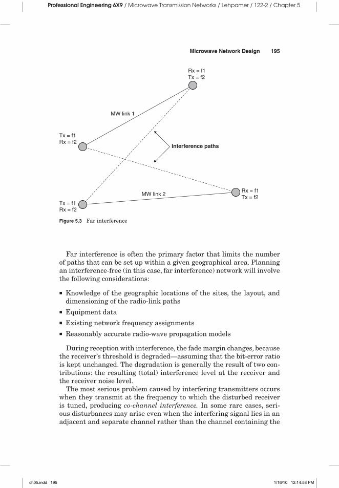
Far interference (also known as far-field interference) is present when a received signal is disturbed by signals that are sent on the same chan-nel (co-channel interference) or an adjacent channel (adjacent-channel interference) and are generated by a transmitter located far away from the receiver (Figure 5.3).
The influence of far interference is first noticeable during fading con-ditions as a deterioration of the receiver threshold level; that is, as a decrease of the path’s fade margin. In interference-free reception, the path fade margin is solely dependent on the path parameters.
Far interference is often the primary factor that limits the number of paths that can be set up within a given geographical area. Planning an interference-free (in this case, far interference) network will involve the following considerations:
n Knowledge of the geographic locations of the sites, the layout, and dimensioning of the radio-link paths
n Equipment datan Existing network frequency assignmentsn Reasonably accurate radio-wave propagation models
During reception with interference, the fade margin changes, because the receiver’s threshold is degraded—assuming that the bit-error ratio is kept unchanged. The degradation is generally the result of two con-tributions: the resulting (total) interference level at the receiver and the receiver noise level.
The most serious problem caused by interfering transmitters occurs when they transmit at the frequency to which the disturbed receiver is tuned, producing co-channel interference. In some rare cases, seri-ous disturbances may arise even when the interfering signal lies in an adjacent and separate channel rather than the channel containing the
desired signal (adjacent channel interference), but this is normally a minor problem in microwave point-to-point networks.
Both horizontal (azimuth) and vertical (elevation) antenna discrimi-nations are generally included in interference calculations.
The ability of digital channels to tolerate interference depends on the modulation scheme.2 In particular, a modulation scheme that requires low C/I for a certain bit-error ratio is more tolerant of interference. Robust modulation schemes are, for example, 2PSK and 4PSK, whereas more complex modulation schemes such as 128QAM require much larger C/I-values.
5.3.4 Frequency Planning
5.3.4.1 Frequency Planning Objectives The objective of frequency plan-ning is to assign frequencies to a network using as few frequencies as possible and in a manner such that the quality and availability of the radio-link path is minimally affected by interference.
The following aspects are the basic considerations involved in the assignment of radio frequencies:
n Determining a frequency band that is suitable for the specific link (path length, site location, terrain topography, and atmospheric effects)
n Prevention of mutual interference such as interference among radio frequency channels in the actual path, interference to and from other radio paths, interference to and from satellite communication sys-tems, and so on
n Correct selection of a frequency band that allows the required transmission capacity while efficiently utilizing the available radio frequency spectrum
Allocation (of a frequency band) refers to the frequency administra-tion of a frequency band for the purpose of its use by one or more ser-vices. This task is normally performed by the ITU.
Allotment (of a radio frequency or radio frequency channel) is the frequency administration of required frequency channels of an agreed frequency plan adopted by a competent conference. These frequency channels are to be used by one or more administrations in one or more countries or geographic regions.
Assignment (of a radio frequency or radio frequency channel) is the authorization given by an administration for a radio station to use a radio frequency or radio frequency channel under specified conditions.
Allotment and assignment are created in accordance with the Series F Recommendations given by the ITU-R. The allotment consists of one or more alternative radio frequency channel arrangements.
These arrangements are used in accordance with the rules of the local administration in a country or geographical region. In most applica-tions, however, frequency bands and frequency channels are already selected and provided to operators.
5.3.4.2 Frequency Channel Arrangements Channels are segments (sub-divisions) of a frequency range or a portion (frequency band) of the electromagnetic spectrum. Every channel has a specified bandwidth and, depending on the capacity of the link, a certain number of carriers can be accommodated in the band.
For instance, a frequency raster may include four adjacent 28-MHz channels (applicable for 34-Mbps links), but each of these channels can be further divided into four 7-MHz channels (applicable for 8 Mbps). To enable four 7-MHz channels to be included within one 28-MHz chan-nel, the center frequencies of the 28- and the 7-MHz channels cannot coincide. Likewise, each 7-MHz channel may be divided in two 3.5-MHz channels (applicable for 2 or 2 × 2 Mbps).
The available frequency band is subdivided into two equal halves: a lower (go) and an upper (return) duplex half. The frequency separation between the lowest frequency in the lower half and that of the upper half is known as the duplex spacing (see Figure 5.4).
Each RF channel requires two frequencies (transmit and receive). All transmit frequencies are in one half of the band, and all receive frequencies are in the other half. Frequencies are normally assigned so that all frequencies transmitting from a site are either in the high half or the low half of the band.
The duplex spacing is always sufficiently large that the intended radio equipment can operate interference-free under duplex operation—
meaning that one channel has one frequency for transmitting and one for receiving. The width of each channel depends on the capacity of the radio link and the type of modulation used.
The ITU-R recommends frequency channel arrangements according to homogeneous patterns given as follows:
n Alternated channels An arrangement of radio channels in a radio link in which two adjacent channels are cross-polarized.
n Co-channel (orthogonal) band reuse An arrangement of radio chan-nels in a radio link in which the same centre frequency is used on two orthogonal polarizations for the transmission of two signals, which may or may not be independent (see also ITU-R Recommendation F.746).
n Interleaved channels band reuse An arrangement of radio chan-nels in a radio link in which additional channels are inserted between the principal channels. The center frequencies of the additional chan-nels are shifted by a specified value, which is a significant proportion (such as a half) of the channel bandwidth from the center frequencies of the principal channels (see also ITU-R Recommendation F.746).
5.3.4.3 The Frequency Planning Process Channel frequencies may be available on a link-by-link basis or as a channel block and may be freely used by the operator. In the first case, it is common that a local fre-quency administration coordinates the use of the frequencies among different users. In the second case, it is up to the operator to coordinate the use of the channels within its own network.
Local frequency administrations usually keep track of the use of available frequency bands and the corresponding channel distribution. Several operators may be forced to share the same frequency band but different channels, thus making it necessary to control such radio-link parameters as transmitted power, site coordinates, antenna heights, and so on.
The most important goal of frequency planning is to allocate avail-able channels to the different links in the network without exceeding the quality and availability objectives of the individual links because of radio interference. Frequency planning of a few paths can be carried out manually but, for larger networks, it is highly recommended that one employ a software transmission design tool.
The frequency planning process can be described as follows:
1. Define the overall structure of the network by determining the location of all the nodes that have to be connected.
2. Allocate the appropriate quality and availability objectives for every portion of the network (no frequencies are involved in this step) and perform quality and availability calculations.
3. Estimate the traffic requirements and capacity. It is a good prac-tice to start frequency planning with highest-capacity links in the most concentrated node. This will normally result in the number of frequencies needed in the network, and other links should reuse the same frequencies.
4. In some cases, it may be necessary to use channels from more than one frequency band as a result of the limited number of available channels in the first selected band.
5. Start assigning a duplex half (lower/upper) for the transmitter in the sites of the network. Generally, near interference should be avoided as much as possible by strictly allocating the same upper or lower duplex half to all transmitters (or receivers) on the same site. Generally, two alternatives are possible:n In a chain of sites, there will be alternating lower/upper sites;
that is, the transmitter in site 1 is L (lower), site 2 is U (upper), and site 3 is L, and so on.
n A microwave ring (using only one frequency band) should always have an even number of hops. In a ring with an odd number of sites, the transmitter of the first site will be assigned the same duplex half as the receiver of the last site (which is the first site in a closed ring), causing serious interference.
6. Consider antenna discrimination aspects in the early stages of frequency planning. For instance, in a common site (e.g., a node or hub), the links having sufficient separation angle may use the same channels. In addition to angle separation, distance separation (coupling loss) between two antennas may also provide a certain degree of discrimination.
7. At microwave frequencies, antenna discrimination increases rapidly with angle separation and is an extremely efficient factor in sup-pressing interference. Thus, if the two links are not closely aligned to a common line and with the (upper or lower) transmitters trans-mitting in the same direction (in other words, no overshoot), it is normally possible to reuse frequencies between two such links.
8. In congested areas it may be necessary to use antennas that have high front-to-back ratios and large side-lobe suppression. These result in good frequency economy and, in the final analysis, good overall network economy. High-performance antennas may be a suitable alternative.
9. Reuse frequencies and polarization as often as possible.
10. Perform a new quality and availability calculation (after the fre-quency allocation) and identify links that do not meet the quality
and availability objectives. Far interference calculation is per-formed, and the receivers having relatively high threshold degra-dation values are probably a part of the links that do not meet the quality and availability objectives.
Make the appropriate changes (polarization, channel, frequency band, antenna size, and so forth) and ensure that a new interfer-ence calculation gives lower threshold degradation values.
11. In some situations, higher output power of a transmitter may improve the quality and availability figures without a significant interference contribution to the network. These favorable situa-tions, however, are not very common, so it is not advisable to use a higher output transmit power than necessary. It is a good idea to start frequency planning with the lowest available output power.
12. If the choice is between higher transmitter output power and larger antennas, choose (if possible) a larger antenna.
13. Repeat step 10 until the quality and availability objectives of all portions of the network are accomplished.
14. Based on the fact that transmitting and receiving frequencies change from site to site, there are two types of sites in the micro-wave system; one is when the receiving frequency is higher than the transmitting frequency, called “high,” and the other one is when the receiving frequency is lower than transmitting fre-quency, called “low.”
High/low site is named based on the receiving frequency.
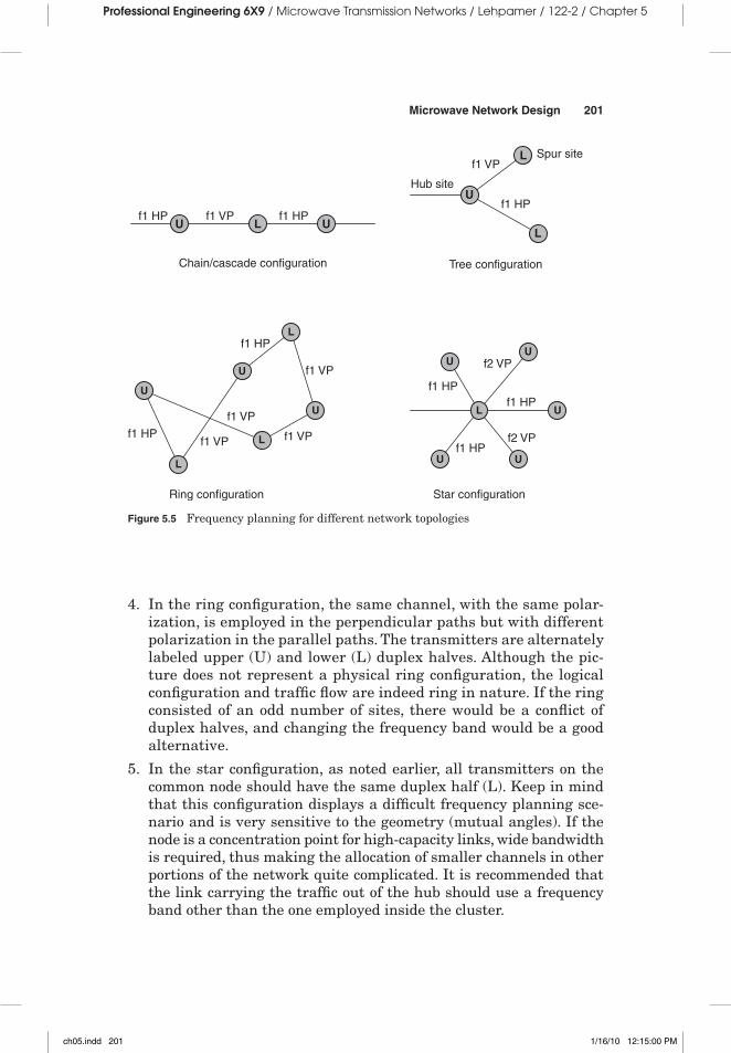
5.3.4.4 Network Topology and Frequency Planning Interference aspects may severely limit the number of links in a network if appropriate caution is not exercised in the earlier stages of frequency planning (see Figure 5.5). In what follows, some general aspects, based on former sections, are illustrated.
1. Since paths of a chain have very sharp angles, using the same chan-nels by changing polarization (HP/VP) may be a good alternative to using two alternate channels in the chain.
2. Figure 5.5 shows the same channel used alternately with horizontal (HP) and vertical (VP) polarization. Upper (U) and lower (L) duplex halves for the transmitters are illustrated in each site.
3. In the tree configuration, and for sharp angles, polarization discrimi-nation ensures the possibility of using the same channel with dif-ferent polarization (HP and VP). Both transmitters on the common node have the same duplex half (U).
4. In the ring configuration, the same channel, with the same polar-ization, is employed in the perpendicular paths but with different polarization in the parallel paths. The transmitters are alternately labeled upper (U) and lower (L) duplex halves. Although the pic-ture does not represent a physical ring configuration, the logical configuration and traffic flow are indeed ring in nature. If the ring consisted of an odd number of sites, there would be a conflict of duplex halves, and changing the frequency band would be a good alternative.
5. In the star configuration, as noted earlier, all transmitters on the common node should have the same duplex half (L). Keep in mind that this configuration displays a difficult frequency planning sce-nario and is very sensitive to the geometry (mutual angles). If the node is a concentration point for high-capacity links, wide bandwidth is required, thus making the allocation of smaller channels in other portions of the network quite complicated. It is recommended that the link carrying the traffic out of the hub should use a frequency band other than the one employed inside the cluster.
Figure 5.5 Frequency planning for different network topologies
6. Mesh configuration presents a complicated frequency planning sce-nario as a result of several conflicts of duplex halves. In addition, it normally requires more channels than do other configurations.
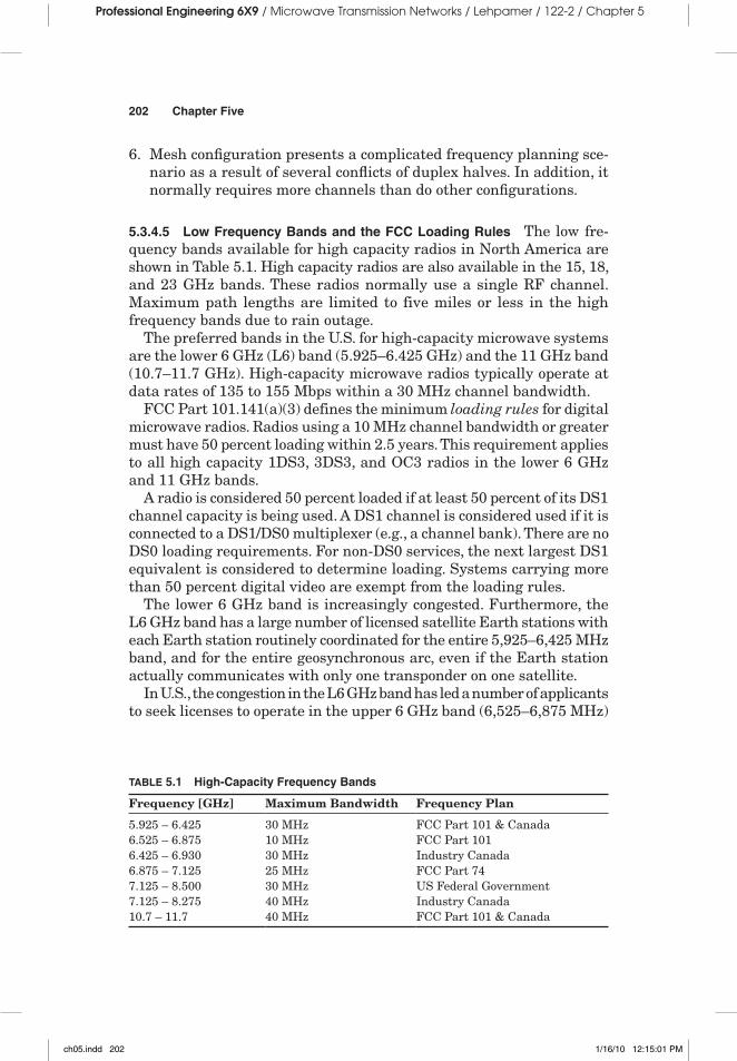
5.3.4.5 Low Frequency Bands and the FCC Loading Rules The low fre-quency bands available for high capacity radios in North America are shown in Table 5.1. High capacity radios are also available in the 15, 18, and 23 GHz bands. These radios normally use a single RF channel. Maximum path lengths are limited to five miles or less in the high frequency bands due to rain outage.
The preferred bands in the U.S. for high-capacity microwave systems are the lower 6 GHz (L6) band (5.925–6.425 GHz) and the 11 GHz band (10.7–11.7 GHz). High-capacity microwave radios typically operate at data rates of 135 to 155 Mbps within a 30 MHz channel bandwidth.
FCC Part 101.141(a)(3) defines the minimum loading rules for digital microwave radios. Radios using a 10 MHz channel bandwidth or greater must have 50 percent loading within 2.5 years. This requirement applies to all high capacity 1DS3, 3DS3, and OC3 radios in the lower 6 GHz and 11 GHz bands.
A radio is considered 50 percent loaded if at least 50 percent of its DS1 channel capacity is being used. A DS1 channel is considered used if it is connected to a DS1/DS0 multiplexer (e.g., a channel bank). There are no DS0 loading requirements. For non-DS0 services, the next largest DS1 equivalent is considered to determine loading. Systems carrying more than 50 percent digital video are exempt from the loading rules.
The lower 6 GHz band is increasingly congested. Furthermore, the L6 GHz band has a large number of licensed satellite Earth stations with each Earth station routinely coordinated for the entire 5,925–6,425 MHz band, and for the entire geosynchronous arc, even if the Earth station actually communicates with only one transponder on one satellite.
In U.S., the congestion in the L6 GHz band has led a number of applicants to seek licenses to operate in the upper 6 GHz band (6,525–6,875 MHz)
TABLE 5.1 High-Capacity Frequency Bands
Frequency [GHz] Maximum Bandwidth Frequency Plan
5.925 – 6.425 30 MHz FCC Part 101 & Canada6.525 – 6.875 10 MHz FCC Part 1016.425 – 6.930 30 MHz Industry Canada6.875 – 7.125 25 MHz FCC Part 747.125 – 8.500 30 MHz US Federal Government7.125 – 8.275 40 MHz Industry Canada10.7 – 11.7 40 MHz FCC Part 101 & Canada
pursuant to waivers that permit them to operate fixed stations in U6 with bandwidths that are greater than the authorized 10 MHz.
These waivers issued by FCC were granted upon showing that there were no channels available in the L6 GHz band, that other higher fre-quency bands were not suitable for the proposed path, and that there were no other alternatives.
5.4 Microwave Design Tools
The International Telecommunications Union (ITU) publishes recom-mendations for the field of telecommunications. Recommendations for telecommunications are published in ITU-T, and recommendations that have been adapted for radio communication are published in ITU-R. The International Organization for Standardization (ISO) and American National Standards Institute (ANSI) are other organizations that promulgate standards, and they are referenced in this book where applicable.
For the proper planning of terrestrial line-of-sight systems, it is nec-essary to have appropriate and widely accepted propagation prediction models, methods, and data. Methods have been developed that allow the prediction of some of the most important propagation parameters affect-ing the planning of terrestrial line-of-sight systems. As far as possible, these methods have been tested against available measured data and have been shown to yield an accuracy that is both compatible with the natural variability of propagation phenomena and adequate for most present applications in system planning.
Most microwave network design software tools are developed by radio manufacturers and therefore are biased toward the manufacturers’ own equipment. In other cases, the tool may be proprietary and not sold on the open market.3 These tools are sometimes provided to engineering personnel who are working on the customer’s site and performing net-work design. While some microwave equipment manufacturers insist on using their own software tools, some operators and consultants prefer to use commercially available tools.
One such vendor-independent tool is Pathloss 5.0 (and the older 4.0 ver-sion). This tool is probably one of the best (and most moderately priced) tools for the complex microwave design, including North American and ITU standards, different diversity schemes, diffraction and reflection (multipath) analysis, rain effects, interference analysis, and others. Radio equipment parameters for equipment from any vendor, channel tables, antenna diagrams, and so on are defined and stored in the default parameters database for easy retrieval.
This tool is widely accepted by microwave system design engineers around the world.
In addition to the strictly microwave path engineering part of the project, there is a system engineering portion. System engineers usually provide technical direction and design to guarantee overall system integrity by verifying that all subsystems and contractor-furnished equipment are compatible, and that the desired performance is realized. Systems engi-neering will also provide transport traffic design and complete system integration as well as the network management system (NMS) and its integration into the other MW and fiber-optic systems.
In the next phase, application engineers review and translate the entire system configuration requirements into specific hardware implementations, including standardized interface levels, intra- and inter-rack cabling, and original equipment manufacturer (OEM) integration requirements, and they produce the following system documentation:
n Criteria, methods, standards, and procedures used for MW path engineering
n A system block diagram that details the main equipment provided by the contractor; all equipment grouped per site with interconnectivity between sites identified
n A block and level diagram that shows all the equipment provided by the contractor; may also show connections, interfaces, and signal levels to existing equipment at the same site
n A T1/E1 plan showing the system traffic routing; shows each T1/E1 connection from the originating site to the destination site
n A channeling plann A synchronization plann Path engineering resultsn A power consumption document that provides the value of the total
power requirements of all equipment provided by the contractor according to the enclosed equipment spreadsheet, on a per-site-basis
n An equipment list (bill of materials) that includes all the equipment that needs to be provided
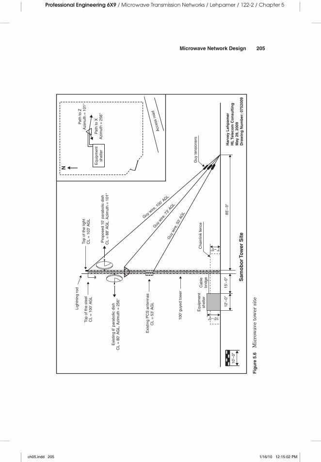
n Site plann A tower profile showing all the radio equipment and transmission
lines installed on the tower (see Figure 5.6)n Floor plans and equipment layout
n A rack profile that shows the equipment mounting position on the rack
n Wiring diagrams showing equipment and inter-rack wiring, cabling, waveguides runs, and so forth
n Geographical system layout
5.5.2 Equipment Availability Calculations
A microwave link can become unavailable for a number of reasons, but this calculation includes only predictable equipment failures. Therefore, it excludes problems caused by misaligned or failed antenna feeder systems, extended loss of primary power, path propagation out-ages, human error, and other catastrophic events.
Short-term (<10 sec) propagation outages are applied to the perfor-mance (not availability) objective and will not be used here.
It is important to define the terms and parameters used in equipment availability calculations as follows:
A = 100 (1 – U) [%] (5.1)
where
A = availability (percentage of time, percent)U = unavailability (percentage of time, percent)
For n pieces of equipment connected in series (tandem),
U = U1 + U2 + … + Un (5.2)
For two pieces of equipment connected in parallel,
U = U1U2 (5.3)
Unavailability of the microwave radio terminal can be expressed as:
U
MTBFMTBF MTTR
UMTTR
MTBF MTTR
= −+
=+
1 (5.4)
where
MTBF = mean time between failure (MTBF = 109/FITS)FITS = failures in time (in 109 hrs)
RT = repair time on siteTT = travel time to the site
P = probability that a spare module is available when neededTR = time to obtain the spare module (assume 24 hrs)
FITS (failures in time) is an internationally used unit for measuring or specifying failure rates. Because individual components or subsys-tems are generally highly reliable in their own right, the convention has arisen of using a period of 109 hrs (114,155 yrs) as a time unit or time scale on which to quantify failure rates (or conversely MTTFs); a failure rate of one failure in 109 hrs equals 1 FIT.
Example:
The typical protected MW terminal (1 + 1) has MTBF of 2,200,000 hrs; it takes 0.5 hrs to do the actual repair at the remote site, and the travel time is 3 hrs. With good maintenance practice and spare parts available, we can assume P = 95 % (or 0.95). Let us calculate unavailability of four MW hops connected in tandem (daisy-chain).
MTTR = 0.5 + 3 + (1 – 0.95)24 = 4.5 hr
Microwave hop (excluding all other equipment) has two terminals in series, so the unavailability is
UHOP = −
+
= ×2 1
2 200 0002 200 000 4 5
4 091, ,
, , .. 110 6−
For the four-hop system, total unavailability is
UTOT = 4 × 0.000004091 = 0.000016364
Total availability is
A U
A
TOT TOT
TOT
= − = −
=
100 1 100 1 0 000016364
99
( ) ( . )
.99984 %
It is important to notice that this number includes only microwave terminals, and all the other equipment is excluded. Calculations that are more detailed should include channel banks and multiplexers, power supplies, and other items.
Total unavailability of the microwave link can then be calculated as a sum of the equipment unavailability and the unavailability due to the propagation issues (rain), i.e., path unavailability.
5.5.3 Availability of Different Network Topologies
The question that very often engineers have to answer is related to the selection of the best and most reliable network topology. Each topology has its advantages and disadvantages, but here we will analyze them from the prospective of the individual microwave path availability/reliability. Unavailability could be caused by hardware failures or propagation problems due to rain, or it could be a combi-nation of both.
Multipath, under normal propagation conditions, typically does not cause traffic outage and therefore does not contribute to unavailability.
So, let us for a moment assume that all the link unavailability values are the same, i.e., U, and calculate and compare average unavailability per cell site for three different network topologies. Shown here is a simplified method of calculation that assumes uncorrelated failures and availability of the switching mechanism (in the ring topology) of 100 percent.
When we say a transport network is “100 percent restorable,” we gener-ally mean that it has a sufficient amount and distribution of spare capac-ity so that any single failure can be withstood without service outage. In principle only dual failures can then cause any service outage. There are increasing numbers of mission critical services calling for as little as 30 seconds (or less) of unavailability per year. This may actually require the ability to withstand certain types of dual failures and motivates analysis of the effects of dual failures on single failure restorable designs.
Dual failure analysis is beyond the scope of this book and will not be discussed here.
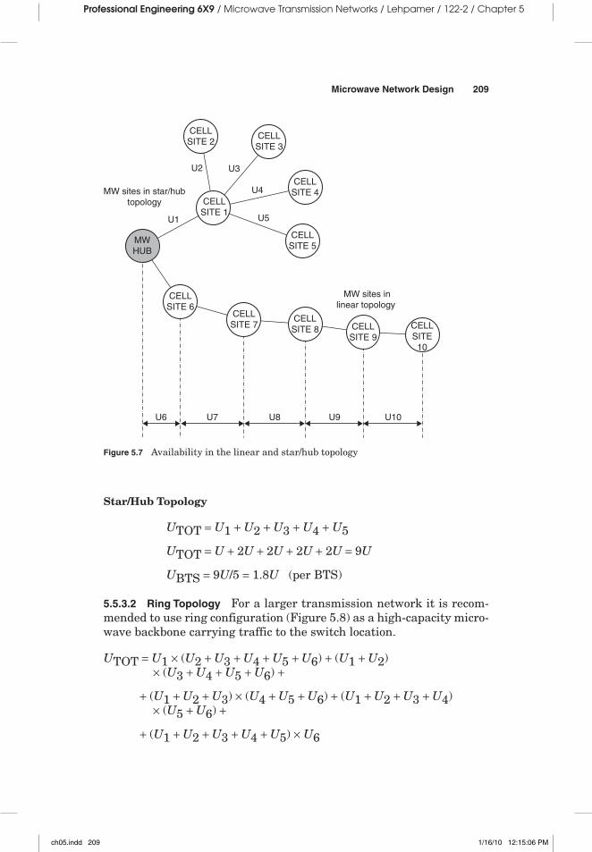
5.5.3.1 Linear and Star/Hub Topology The following calculation, based on Figure 5.7, shows an average improvement of 40 percent in BTS availability (or reduction in unavailability) for the star/hub network topology over linear (daisy-chaining) topology.
5.5.3.2 Ring Topology For a larger transmission network it is recom-mended to use ring configuration (Figure 5.8) as a high-capacity micro-wave backbone carrying traffic to the switch location.
If we assume that the microwave link availability is 99.999 percent (0.001 percent unavailability) we can calculate the average unavail-ability per BTS for three different topologies.
For the linear topology of the five cell-site network, the average unavailability per BTS is 0.003 percent (availability = 99.997 percent); for the star/hub topology, the average unavailability per BTS is 0.0018 percent (availability = 99.9982 percent), and for the ring topology, 0.00000007 percent (availability = 99.99999993 percent). Although this is just an illustration, the advantage of using ring topology from the increased availability prospective is obvious.
Let us now consider a secondary ring connected to a node in the primary ring (see Figure 5.9). The secondary ring has links with lower capacity than the primary ring, so the traffic can only flow from the secondary to the primary ring. The total unavailability of a specific node in the secondary ring is calculated by adding the unavailability of the node in the primary ring, cell-site 3, to the unavailability calculated at that specific node in the secondary ring.
The unavailability of a specific node in the secondary ring is obtained similarly as in the primary ring. The unavailability of more secondary rings can be calculated in the same way.
Again, for the sake of simplicity, we will assume that all the unavail-abilities are the same (this will never be the case in the real networks, but the calculation principles will be the same,) i.e., U:
UBTS3 = 3U × 3U = 9U2
UBTS7 = 3U × 3U + 2U × 2U = 9U2 + 4U2 = 13U2
So, if U = 0.001%, UBTS3 = 0.00000009%, ABTS3 = 99.99999991%, and UBTS7 = 0.00000013%, ABTS7 = 99.99999987%.
Important: Note that percentages can be added and/or subtracted directly but cannot (a common mistake) be multiplied or raised to the power without prior conversion into the decimal number. Here is the example of detailed calculation:
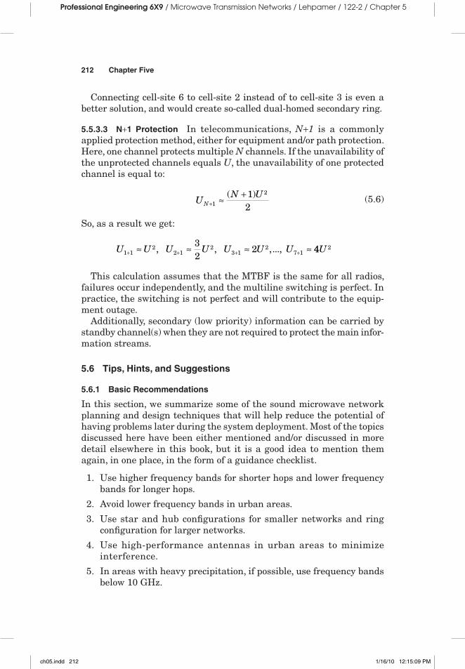
Connecting cell-site 6 to cell-site 2 instead of to cell-site 3 is even a better solution, and would create so-called dual-homed secondary ring.
5.5.3.3 N+1 Protection In telecommunications, N+1 is a commonly applied protection method, either for equipment and/or path protection. Here, one channel protects multiple N channels. If the unavailability of the unprotected channels equals U, the unavailability of one protected channel is equal to:
UN U
N+ ≈ +1
212
( ) (5.6)
So, as a result we get:
U U U U U U U1 1
22 1
23 1
27 1
32
2+ + + +≈ ≈ ≈ ≈, , ,..., 44 2U
This calculation assumes that the MTBF is the same for all radios, failures occur independently, and the multiline switching is perfect. In practice, the switching is not perfect and will contribute to the equip-ment outage.
Additionally, secondary (low priority) information can be carried by standby channel(s) when they are not required to protect the main infor-mation streams.
5.6 Tips, Hints, and Suggestions
5.6.1 Basic Recommendations
In this section, we summarize some of the sound microwave network planning and design techniques that will help reduce the potential of having problems later during the system deployment. Most of the topics discussed here have been either mentioned and/or discussed in more detail elsewhere in this book, but it is a good idea to mention them again, in one place, in the form of a guidance checklist.
1. Use higher frequency bands for shorter hops and lower frequency bands for longer hops.
2. Avoid lower frequency bands in urban areas.
3. Use star and hub configurations for smaller networks and ring configuration for larger networks.
4. Use high-performance antennas in urban areas to minimize interference.
5. In areas with heavy precipitation, if possible, use frequency bands below 10 GHz.
6. If bands above 10 GHz have to be used, consider microwave radios with adaptive modulation.
7. Use unprotected systems (1 + 0) only for spur sites, low capacity and/or generally low-importance links. Use protected systems (1 + 1) for all important and/or high-capacity links.
8. Leave enough spare capacity for future expansion of the system.
9. Below 10 GHz, multipath outage increases rapidly with path length. Multipath effects can be reduced with higher fade margins. If the path has excessive multipath outage, the performance may be improved by using one of the diversity methods.
10. The reflection coefficient (and therefore chances of multipath fading) decreases with frequency.
11. Vertical polarization is less susceptible to reflections.
12. Vertical polarization is less susceptible to rain attenuation.
13. Space diversity is a very expensive way of improving the perfor-mance of the microwave link, and it should be used carefully and as a last resort.
14. The activities of microwave path planning and frequency plan-ning preferably should be performed in parallel with line-of-sight activities and other network design activities for best efficiency. In addition, start the official process of frequency coordination and licensing process as soon as possible.
15. Use updated maps that are not more than a year old. Magnetic inclination as well as the terrain itself can change drastically in a very short time period. Make sure that everyone on the project is using the same maps, datums, and coordinate systems.
16. The datum or reference ellipsoid selection must be the same for the site data, image, and elevation files. The same map projection must be used for the image and elevation files.
17. Avoid using design software programs with unknown algorithms. This could result in a microwave radio network with poor perfor-mance and quality.
18. Consider future network expansions in the frequency planning activity. It must be possible and easy to add new hops as the net-work expands.
19. Perform detailed path surveys on all microwave hops. Maps are used only for initial planning, as a first approximation (see Chapter 6 for details on performing site/path surveys).
20. Keep in mind during the path surveys that trees and other vegeta-tion grow, and plan for at least 10-yr growth, preferably even 20 yrs.
If trees are already matured, their rate of growth is slower than the young trees. There are very few areas where trees will grow over 100 ft.
21. Make sure that all of the obvious requirements are fulfilled (i.e., enough space for the transmission equipment, available AC and DC power, enough space for antenna installation and panning, access to the site, and so forth).
22. It is very important to use an expert tower company to calculate the loading of the tower and the maximum allowed twist and sway of the structure. These decisions cannot be made on the basis of qualitative perceptions or a gut feeling. Do not try to save money by using the “ballpark” method!
23. Obtain microwave radio, transmission lines, antennas, and so forth only from a reputable and reliable supplier.
24. Hire an experienced project manager, preferably with recent involve-ment in a similar type of microwave project. Use lead engineer(s) to support and provide help for the less experienced project man-ager.
25. Waveguide installation is an extremely tricky operation—use only expert waveguide installers and riggers. People installing PCS and cellular antennas are not necessarily qualified for microwave antenna and waveguide installation.
26. Keep a good record of all the design documentation, survey reports, change orders, ATP results, and so on. Many of the long-term test results later will be useful as a benchmark for maintenance and troubleshooting.
27. Finally, do not try to over-dimension the network, as this will make it unnecessarily costly. Every network, regardless of the type, will have brief outages from time to time, and microwave networks are no exception. A network that does not fail is a fiction.
5.6.2 Difficult Areas for Microwave Links
Some areas are more difficult for microwave links than others, and this is usually related to path or atmospheric conditions.4
An example of difficult conditions for microwave links is connecting offshore (gas or oil) platform to the mainland; a very challenging under-taking indeed. First of all, the platform itself is a continuously moving object and any radio solution would have to be able to cope with the continual movement of the sea. Second, some areas where we find these platforms (Middle East or North Africa, for example) have a wide tem-perature range, i.e., extremely hot during summer days, with much lower
temperatures during the night and in winter. This will cause anomalous propagation conditions that alter and can cause significant fading. Third, the distances involved are usually long, and there is a limit on the height of metal structures because of safety regulations.
The following is a partial list of recommendations for the design and installation of microwave links in difficult areas:
1. In areas with lots of rain, use the lowest frequency band allowed for the project. Consult a local meteorological station for the “real” rain data and rely on the Crane or ITU rain maps only if no other information is available.
2. Be especially attentive during the design of microwave hops over or in the vicinity of the large water surfaces and flat land areas, as they can cause severe multipath fading. Reflections may be avoided by selecting sites that are shielded from the reflected rays.
3. Swamp and rice fields may cause ground reflections so there is a high probability of multipath fading. The worst time of the year is the rainy season, also called the monsoon season.
4. Hot and humid coastal areas have a high ducting probability.
5. Desert areas may cause ground reflections, but sand does not have a high reflection coefficient. Most critical is the possibility of multipath fading and ducting caused by large temperature variations and/or temperature inversions.
6. Multipath typically occurs at sunrise, sunset, and during the night hours, when the air is calm, and stable refractive layers form in the atmosphere. Multipath is most common during the summer months, when temperature and humidity differences are the most extreme.
In North America, multipath outages are most severe near the Gulf of Mexico, the Great Lakes, and the Los Angeles basin, where humid air masses mix with dry continental air masses. Multipath is much less common, for example, in the Rocky Mountain area, where air circulation in the mountains prevents the formation of stable atmosphere.
7. If upfading is a serious problem, smaller antennas, lower transmit power, or receiver attenuators can be used. These changes will improve upfade outage but can be used only on shorter paths, since this approach will reduce fading margins to combat multipath and rain. ATPC will reduce upfade outages without affecting the fade margin.
If the angle of the path line to horizontal is more than 0.5°, upfading is not significant and can be ignored, since the microwave signal can penetrate the ducting layers that cause upfade.
1. ITU-R Recommendation P.452-7, “Prediction Procedure for the Evaluation of Microwave Interference between Stations of the Surface of the Earth at Frequencies above About 0.7 GHz,” 1995.
2. TIA, Telecommunications Systems Bulletin, TSB-10-F, Interference Criteria for Microwave Systems, 1994.
3. Lehpamer, H., Transmission Systems Design Handbook for Wireless Networks, Norwood, MA: Artech House, 2002.
4. Henne, I. and Thorvaldsen, P., Planning of Line-of-Sight Radio Relay Systems 2nd ed., Singapore: NERA Telecommunications, 1999.