C.P. No. 1127 LI::R?.R Y ROYAL AI 7RAFT ESTAECISHMENT - ma?~. MINISTRY OF TECHNOLOGY AERONAUTICAL RESEARCH COUNCIL CURREN J PAPERS Liquid and Vapour Cooling Systems f or Gas Turbines 6y J. P. Edwards, NG JE, Pyestock LONDON: HER MAJESTY’S STATIONERY OFFICE 1970 PRICE 5s Od [25p] NET
Transcript
C.P. No. 1127
LI::R?.R Y ROYAL AI 7RAFT ESTAECISHMENT
- ma?~.
MINISTRY OF TECHNOLOGY
AERONAUTICAL RESEARCH COUNCIL
CURREN J PAPERS
Liquid and Vapour Cooling Systems f or
Gas Turbines
6y J. P. Edwards,
NG JE, Pyestock
LONDON: HER MAJESTY’S STATIONERY OFFICE
1970
PRICE 5s Od [25p] NET
C.P. No.1127*
November 1969
Liquid and vapour coolmg systems for gas turbines
- by -
J P Edwards NGTE Pyestock
SUMMARY
Thu Note ducusses the application of several types of liquid and
vapour cooling systems to gas turbine blade coolmg, with emphasis on systems
sultable for continuous operation. The application of the 'heat pipe' concept
to stator blade cooling is discussed in scme detail and a tentative design
study presented.
*Replaces A.R.C.30 9%
CONTENTS
1.0 Introauctlon
2.0 Thermodynannc considerations
3.0 Use of fuel as a heat sink
4.0 Closed cn-cult heat transfer dences
4.1 Thermosyphons for rotating blades
44:: Vapour chambers for rotating blades 'Heat pipes' for stator cooling
4.4 Pumped closed cn-cuit liquid cooling
5.0 Liquid metal technology
6.0 Conclusions
References
No.
I
II
APPENDICES
Title
Heat pipe n.g.v. cooluvg system
Pumped liquid sodum system
ILLUSTRATIONS
FIR. No. Title
1 Some coolmg schemes
2 Heat transfer devlCSS
3 Heat pipe performance
w
3
3
4
4
4
: 6
7
a
10
12
2
,
1.0 Introauctlon
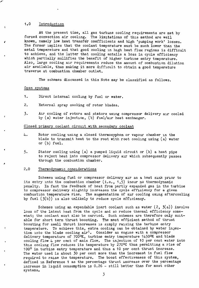
At the present time, all gas turbine cooling requirements are met by forced convection air cooling. The limitations of this method ape well known, namely low heat transfe'r coefficients and high 'pumping work' losses. The former Implies that the coolant temperature must be much lower than the metal temperature and that good cooling III high heat flux regions is difficult to achieve, and the latter that cooling entails a loss in cycle efficiency whioh partially nullifies the benefit of higher turbine entry temperature. Also, large cooling air requirements reduce the amount of combustion dilution air available, thus making it more dlffxult to obtain .s good temperature traverse at combustion chamber outlet.
The schemes discussed in this Note may be classified as follows.
Open systems
1. Direct internal cooling by fuel or water.
2. External spray cooling of rotor blades.
3. Air cooling of rotors and stators using compressor delivery air cooled by (a) water injectlon, (b) fuel/air heat exchanger.
4. Rotor cooling using a closed thermosyphon or vapour chamber in the blade to transmit heat to the root with root cooling using (a) water or (b) fuel.
5. Stator cooling using (a) & pumped liquid circuit or (b) a heat pipe to reject heat into compressor dellvery au‘ which subsequently passes through the combustion chamber.
2.0 ThermoQnamx consderations
Schemes using fuel or compressor delivery air as a heat sxdc prior to its entry Into the combustion chamber (i.e., 1,5) incur no thermodynamic penalty. In fact the feedback of heat from partly expanded gas in the turbine to compressor delivery slightly increases the cycle effxiency for a given combustion temperature rise. The augmentation of ar cooling using aftercooling by fuel (j(b)) 1s also unlikely to reduce cycle efficiency.
Schemes using an expendable inert coolant such BS water (2, 3(a)) involve loss of the latent heat from the cycle and so reduce thermal efficiency some- what; the coolant must also be oarrxed. Such schemes are therefore only suit- able for short term thrust boosting. The most efficient method of thrust boosting for small thrust increases IS supply raxing the turbine entry temperature. To achieve this, extra cooling can be obtained by water inJec- tion into the blade cooling airl. Consider an engine with B compressor delivery temperature of TOOOK, turbine entry temperature 145OoK and blade cooling flow I+ per cent of main flow. The lnjectlon of 10 per cent water into this ooollng flow reduces its temperature by 270°C thus permitting a rise of 100° in turbine entry temperature and thus a IO per cent thrust increase. The water used is about 30 per cent more than the increment in fuel flow required to raxe the temperature. The boost effectiveness of this system, defined m Reference 1 as the percentage thrust increase over the percentage Increase in liquid consumption 1s 0.26 - still better than for most other systems.
3
With the exception of scheme 4(a), in aircraft engines heat is not lost from the cycle and indeed the heat extracted by the coolinn system must be reJected at relativelv hxh temueratures. Whiist this is Looi thermodvnamic-
- I
ally, it puts a premium on cur ability to transport large amounts of heat the smallest possible temperature drop. Means of achieving this using llquds and vapour systems will be discussed.
3.0 Use of fuel as a heat sink
In high speed aircraft, the fuel is very much in demand as a heat sink for the cooling of electrical and other systems as well as for the engine oil. For kerosene we night assume that fuel becomes available for blade cooling at about 150cC. The amount of heat which can be absorbed is thus largely controlled by the temperature at whch sold rexdues are formed by reactions m the fue12. With proper precautions3 this could be raised to the critical temperature (373cC) or above. The heat absorbed at the critxal pressure 350 p.s.i. would then be 158.4 C.h.u. lb-l (6.62 x IO8 J kg-' ) (Reference 4). Somewhat more heat would be absorbed lower pressures, but the tendency to form sold deposits would increase.
for
at
For a fuel/air ratio of 0.025, B cooling airflow of 6 per cent could be cooled by 26occ (scheme j(b)). Some development of the burner would be necessary to cope with fuel at such a high temperature but this does seem feasible. If the use of liquid methane as a fuel is envisaged, the situation is even better. However much mere heat will be absorbed by the fuel tanks so let us suppose that the latent heat, 121 C.h.u. lb-l (5.06 x IO'J kg-l ) has been supplied and that after compression and passage thmugh the oil cooler, the gasis at 150%. It should be possible to heat the gas by another 4OOcC, thus absorbing 311 C.h.u. lb-' (13 x IO" J kg-' ). Allowing for the lower fuel flow (87 per cent of that for kerosine), the heat sink capacity is 70 per cent greater5. These temperature limits are mere conservative than those quoted. in Reference 6 i.e., 810 and 920cK for kerosene and methane. Decomposltlon of methane into hydrogen and solid carbon is reduced by in- creasing pressure but is stronglyinfluenced by the nature of the heating surfaces7. A heat exchanger for this system could be mounted between the HP turbine shaft and the combustion chamber inner annulus.
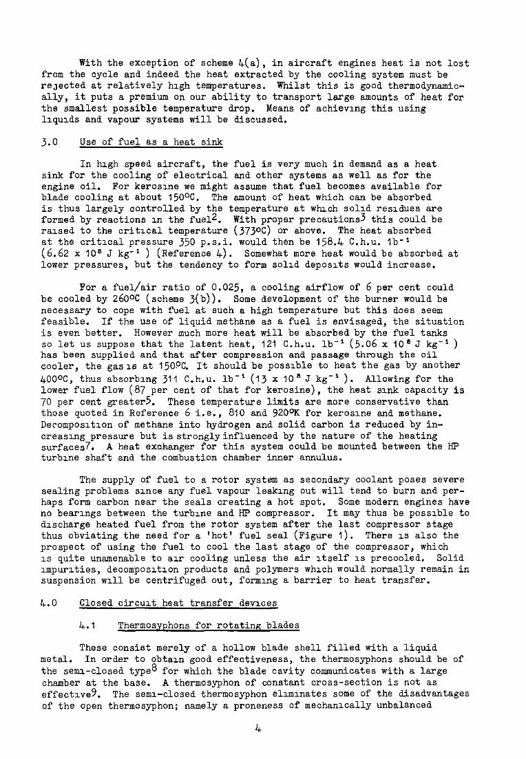
The supply of fuel to B rotor system as secondary coolant poses severe sealing problems since any fuel vapour leaking cut will tend to burn and per- haps form carbon near the seals creating a hot spot. Some modern engines have no bearings between the turbine and HP compressor. It may thus be possible to dxcharge heated fuel from the rotor system after the last compressor stage thus obviating the need for a 'hot' fuel seal (Figure 1). There 1s also the prospect of using the fuel to cccl the last stage of the compressor, which 1s quite unamenable to au‘ cooling unless the air Itself 1s precooled. Solid Impurzties, decomposltlon products and polymers which would normally remain in suspension ~111 be centrifuged cut, forming a barrier to heat transfer.
4.0 Closed circuit heat transfer devxes
4.1 Thermosyphons for rotatinp blades
These consist merely of a hollow blade shell filled with a liquid metal. In order to cbtaln good effectiveness, the thermosyphons should be of the semi-closed type8 for which the blade cavity communicates with a large chamber at the base. A thermosyphon of constant cross-section is not as effed1ve9. The semi-closed thermosyphon ellmlnates scme of the disadvantages of the open thermosyphon; namely a proneness of mechanically unbalanced
4
i
Operation and the deposition of solid material in the blind ends of the blade cavltles. The devxe described in Reference 8 operated with a llquld metal to blade heat transfer c;efficlent of 32.5 kW m * oC-' and a liquid to root value of 5.08 kW m-' 262.8OC respectlvely.°C-
giving temperature differences of 22.2 and
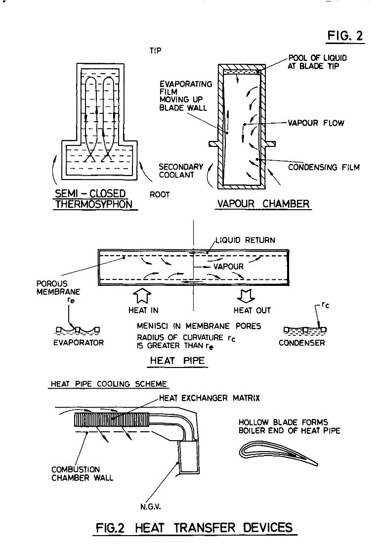
4.2 Vapour chambers for rotating blades
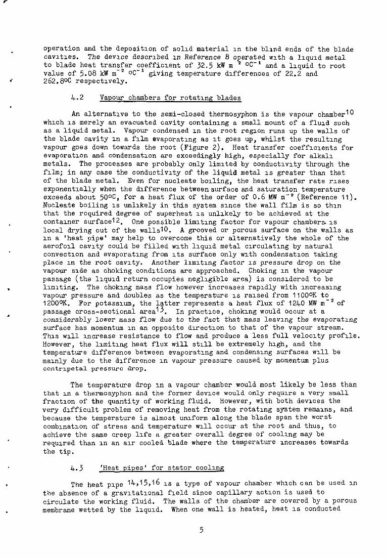
An alternative to the semi-closed thermosyphon is the vapour chamber'0 which 1s merely an evacuated cavity containing a small mount of a fluid such as a liquid metal. Vapour condensed in the root regxon runs up the walls of the blade cavity 1n a film evaporating as It goes up, whilst the resulting vapour goes down towards the root (Figure 2). Heat transfer coefflclents for evaporation and condensation are exceedingly high, especially for alkalz metals. The processes are probably only limited by oonductlvlty through the fxlm; in any case the conductivity of the liquid metal IS greater than that of the blade metal. Even for nucleate boiling, the heat transfer rate rses exponentially when the dU?ference betweensurface and saturation temperature exceeds about 5OoC, for a heat flux of the order of 0.6 MW rn-' (Reference 11). Nucleate boiling 1s unlikely in this system since the wall film is so thxn that the required degree of superheat 1s unlikely to be achieved at the contalner surfacel2. One possible limltlng factor for vapour chambers. 1s local drying out of the wallslO. A grooved or porous surface on the walls as in a 'heat pipe' may help to overcome this or alternatively the whole of the aerofoll cavity could be filled with llquld metal clrculatlng by natural convection and evaporating from Its surface only with condensation taking place .xn the root cavity. Another llmltlng factor 1s pressure drop on the vapour side as choking conditions are approached. Choking in the vapour passage (the llquld return occupies negligible area) is conszdered to be
. llmlting. The choking mass flow however increases rapidly with IncreasIng vapour pressure and doubles as the temperature 1s razsed from IlOOoK to 12000K. For potsslum, the latter represents a heat flux of 1240 MW to-* of
. passage cross-sectional area'3. In practice, choking would occur at a considerably lower mass flow due to the fact that mass leaving the evaporating surface has momentum in an opposite dlrectlon to that of the vapour stream. Ths ~111 Increase resistance to flow and produce a less full velocity profile. However, the llmitlng heat flux will still be extremely high, and the temperature difference between evaporating and condensing surfaces ~111 be mainly due to the difference in vapour pressure caused by momentum plus centr1peta1 pressure drop.
The temperature drop in a vapour chamber would most likely be less than that m a thermosyphon and the former device would only require a very small fraction of the quantity of working fluid. However, with both devxes the very difficult problem of removing heat from the rotating system remains, and because the temperature is almost unzform along the blade span the worst comblnatlon of stress and temperature ~111 occur at the root and thus, to achieve the same creep life a greater overall degree of cooling may be requzed. than in an air cooled blade where the temperature Increases towards the tip.
4.3 'Heat pipes' for stator coollnq
The heat pipe 14,'5,'6 1~ a type of vapour chamber which can be used in the absence of a gravItatIona field since capillary actlon is used to circulate the working fluid. The walls of the chamber are covered by a porous membrane wetted by the 1lquxL When one wall is heated, heat 1s conducted
5
through the llqud filled membrane and llqud evaporates from the menlscl in the pores. Its place is taken by liqud drawn in by capillary actlon fram other parts of the 'wick'. Lxquid 1s thus pumped from the condensing to the evaporating regun. The 'head' avadable 1s proportional to the curvature of the meniscus in a pore of the wick and 1s of course proportional to the surface tenslon (Fxgure 2).
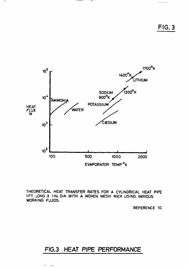
The fluid must have a high thermal conductlnty so that heat can be conducted through the liqud under the ~membrane wlthout the surface super- heat becomlng high enough to lnitlate nucleate boding. The total pressure drop (liquid side + vapour side + gravitatIona head) must not exceed that obtainable by capillary actlon. The only fluids worth consideration for the turbine cooling applicatlcn are lithuxn, sodium and potassium. Although lithium has the largest latent heat and surface tennon, Its vapour pressure 1s too low at the temperatures envisaged at present (I.e., around 12OOcK). As in the case of the rotating vapour chamber the heat carrying capacity ncreases rapxdly with temperature (Figure 3) owmg to the uxrease in vapour mass flow for a given pressure drcp, though in a heat pipe, there 1s some decrease in the available 'driving' pressure due to decrease in surface tensIon and increase in viscous loss in the liqud stream with lncreaslng mass flow. The condenser section must on no account be overcooled wlvlst appreciable heat fluxes are being supplled to the boiler section, otherwxe the boder may be 'starved' and heat pipe action will cease abruptly. Under these conditions the vapour may attain sonic velocity, in whxh case further reduction in the vapour pressure in the condenser will not ncrease the flow but will prevent liquid from returning to the boder. Hence heat pipe systems should reJect heat to a gas stream which 1s already faxly hot I.e., compressor &livery air as m scheme 5(b). Some care wdl be neeaea during the engine starting cycle. Also when the dynsm~ head of the vapour stream 1s high, droplets of liqud may be detached from the wick surface and en- traIned in the vapour stream. This Increases the fluid circulation wlthout benefit to heat transfer, and pressure drop increases until, again, the heat pipe fads.
Appenbx I contans atentatlvedeslgn study by the author for a first stage stator blade cooling system for use on a large engine with a turbine entry temperature of 1620cK. The heat pipe operates wlthln the 'entrainment lunt' as given by the formula UY Reference 17.
4.4 Pumped closed circuit liquid coolu-~g
Amongst the fluids which have been proposed for this application are hydrocarbons such as diphenyllS, fluorinated hydrocarbons such as perfluorodecalin (which can be used as the working flud m an auxiliary cycle) and of coWse llquld metals. Chemical stability reqdirements are more stringent for closed systems and the hydrocarbons have operating temperature limits around &OOcC, not much in excess of those for fuels. However, the prospects for llquld metal cooling of static parts are very good and the use of electromagnetic pumps, which are being developed for high temperature use, ~111 permit a hermetically sealed system to be desIgned. Appendix II gives scme design details of a llqud sodium system in a sunialr application to the heat pipe mentloned above. However, the system may be lurnted to non-aeronautical use by the tifflculty of servicing a system where all the pipe Joints are welded up. In the heat pipe system, each blade with Its heat pipe and cooler J.S treated as a separate self-contained unit and so poses no I?lsmant.ling problems.
6
.
5.0 Liquid metal technolo~
Some past attempts to use liqud metals for gas turbine cooling have failed due to chemical reaction between impurltles, the liquzd metal and the contamer. However a great deal of work has been done in recent yews In the USA and In Britain in connection with nuclear power systems, in particular those for use in space and for fast reactors. Using the correct techniques it should be possible to obtain lives of thousands of hours from liquid metal devxes. A molybdenum alloy-lithium heat pipe has operated for 3820 hr at 1767% (Xeference 14). The corrosion problem can largely be overcome by elun.xnatlng all traces of oxygen fram the system and using 'getters' such as barium and zuconium. These also improve the wetting properties of the flud. Another problem, however is that of mass transport. Although nickel based alloys are not readily attacked by alkali metals they are slightly soluble at high temperatures. In evaporatwg systems, this will cause a transport of material from the condenser section to the evaporator section. In non-evaporating systems metal ~111 dissolve preferentially In the hotter parts of the system and be deposited In the cooler part. Refractory metals such as tungsten and molybdenum have very low solubdltles in alkali metals but have very little oxidation resdxnce and are thus uw suitable for parts In contact with hot combustion gases. The problem could most likely be solved by uszng a refractory metal llnlng in a nickel alloy blade assembly. Thus could either be a fabricated liner with the nickel alloy castaroundit, or * vapour deposIted Internal coating. Thus liner would also serve as a bawler against dlffuslon of dloying elements and adsorbed gases into the liqud metal. In heat pipes, It may also be necessary to remove all gases, since they may give rise to nucleate bolling12.
6.0 Conclusuns
Several ways in whxh llquds can be appl~d to turbue cooling have been described. In the rotor coolug system using primary coolant, the problem of removu?g heat from the rotor 1s stdl very severe. If llqud cooling is used, there is a sealing problem. With au cooling the problem 1s that of providing a large area heat transfer surface near the root. The use of fuel as heat suk to augment au cooling would seem more promuing; the application of the 'heat pipe' to the cooling of stator blades and for equalwing the temperatures of casings and stationary shrouds In order to mlnimue dIstortion seems well worth investigating. Both applications promxse improved thermal efficiency by reducing the proportion of working flud diverted for cooling purposes and reducing leakage losses.
REFERENCES
No. Author's
1 J. F. Barnes F. w. Armstrong
2 J. D. Smith
3
4 K. Ross
5
9
10
J. D. Smith
F. S. Stepka
G. Egloff
V. A. Ogale
F. J. Bayley G. S. H. Lock
H. Cohen F. J. Bayley
Title, etc.
A brief renew of thrust boostug techniques. (A paper produced for the 75th meeting of the G.T.C.C.) April 1965
Aviation turbine fuels. Factors affecting thermal stability. 'Shell' Research Limited,
Report No. K.160, November 1964
Aviation turbine fuel thermal stability. The effect of nitrogen Pwglng. 'Shell' Research LimIted, Report No. K.159, May 1964
The specific heat of anation turbine fuels in the liqud phase. 'Shell' Research Lnnted, Report No. K.161, November 1964
Selected values of propertzes of hydrocarbons. National Bureau of Standards November 1947
Consderations of turbne cooling systems for Mach 3 flight. NASA TN 04491, April 1968
Reactions of pure hydrocarbons Remhold 1937
On the application of the semi- closed thermosyphon system to gas turbine blade cooling. Thesx. Technologxal University of Delft, September 1968
Heat transfer chsracteristlcs of the closed thermosyphon. Trans. ASKE Series C, Vol. 87, February 1965
Heat transfer problems of llqud cooled gas turbine blades. Proc.I.Mech.E., Vol. 169, No. 20, 1955
‘,
t
8
NO.
11
12
13
14
15 T. P. Cotter
16
17 J. E. Kemme
REFERENCES (cont'd)
Author(s)
C. B. Jackson et al
Title, etc.
Liquid metals handbook. Sodvxn (NaK) supplement. Atomic Energy Commission, Department of the Navy, Washington, D.C., July 1955
J. G. Collier P. G. Kosky
Natural convectlve boiling of the alkali metals - A crltlcal renew. AKRE R.5436, September 1967
A. H. 0. Brown SO&LUIU and N&C. The natural convection cycle wth reference to turbwe blade cooling. British Sddeley Engnes Limited, Ref. GN 4257, February 1961
K. T. Feldman G. H. Whiting
H. May
The heat pipe. Mechanical Engineering, Vol. 89, No. 2, pp.30-35, February 1967
Theory of heat pipes. Los Alamos Sclentlfic Laboratory LA-3246~MS, March 1965
Proceedings of Joint Atomic Energy Commiss~on/Sandxa Laboratories Heat Pipe Conference. Sandia Corp., Alberquerque, N. Mex., October 1966
High performance heat pipes. Los Alamos Sclentlflc Laboratory LA-DC-9027. Presented at the 1967 Thermlonlc Conversion Speclallst Conference Palo Alto CalIf., 30th October, 1967
Investigations of fofced convection liquid cooled gas turbine blades. ASME Journal of Engineering for Power, January 1965
9
APPENDIX I
Heat pipe n.g.v. coolu-~g system
Turbine entry temperature
Compressor delivery temperature
Total pressure
Blade Reynolds number
Nusselt number
Chord
Spa
Gas thermal conductlvxty
Blade metal conductivity
Gas mass flow per blade
Blade outer surface temperature
Heat flux per blade
Evaporator surface temperature
Degree of superheat at Inner wall
Sodium latent heat
Sodium coolant mass flow
Coolant vapour pressure
Area of vapour passage out of blade
Surface tension
Velocity heat of vapour in pipe ($-pV2 )
Let overall pressure drop be 2 x velocity head m vapour p'pe, then liqud pressure drop is:- Making a 10 per cent allowance for adtitxonal pressure drops:- pore diameter 1s:
Llquld viscosity
Pipe length
1620%
910%
1.1 x IO' N m-'
108
700
5.08 cm
10.16 cm
9.65 x IO-*W m-'cK-l
27.4 w mm1 OK-'
1.455 kg s-l
1220%
6.35 kW
11690~
20%
4.21 x IO6 J kg-'
1.5 g s-1
1.172 ~10~ N me2
1.26 cm2
0.112 N me*
2.85 x IO3 N me2
2.85 x 10³ N m-2
0.7 x 10d2 cm
0.015 kg m-l s-l
15 cm
10
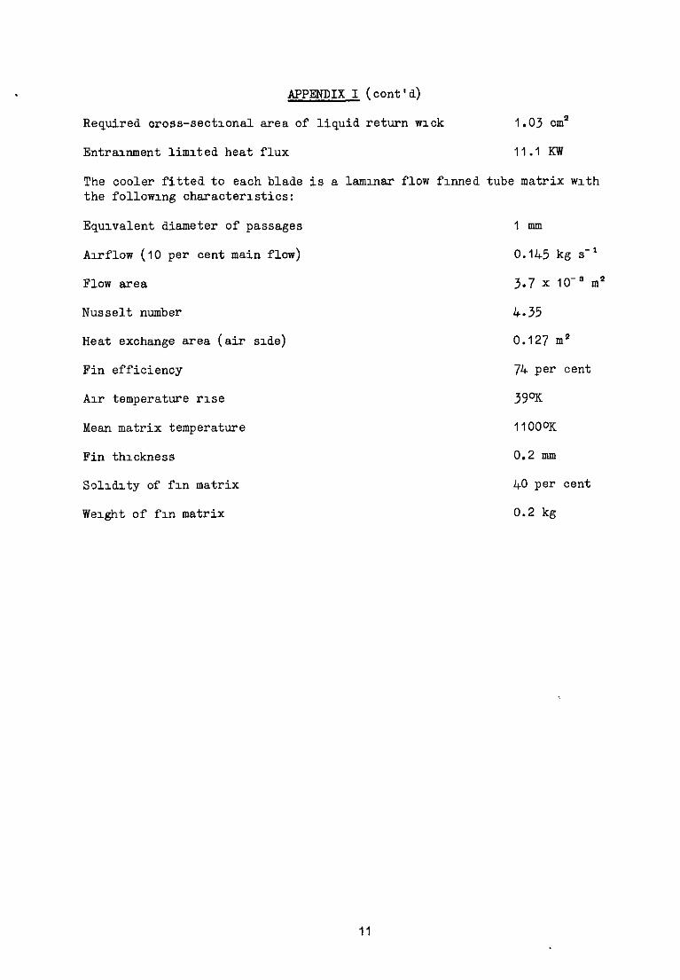
APPENDIX I (cont'd)
Required cross-sectvmal area of liquid return wick 1.03 cm*
Entramment limted heat flux 11.1 Kw
The cooler fitted to each blade is a lammar flow fumed tube matrix mth the followmg characteristics:
Equivalent diameter of passages IUIIS
Axflow (10 per cent main flow) 0.145 kg s-l
Flow area 3.7 x 10-O In2
Nusselt number 4.35
Heat exchange area (air sde) 0.127 m'
Fin efficiency 74 per cent
Au- temperature rise 39%
Mean matrix temperature IIOOOK
Fin thickness 0.2 mm
Soldlty of fm matrix 40 per cent
We&t of fm matrix 0.2 kg
11
APPENDIX II
Pumped lwuid sodium system xblade operating condltmns smiler to prenous example)
Coolant flow 2 per cent of engine mass flow
Temperature rise of coolant
Flow passage in blade (flat se&Ion)
Blade outsde surface temperature (mean)
Blade mslde surface temperature (mean)
Coolant inside surface temperature difference
Flow velocity m cooling passage
Velocity head ($pV ') m cooling passage
Let total pressure drop ~.n coolant ou-out be equal to 10 x veloolty head in blade passage and pump efficlenoy be 15 per cent then electrxal pumpmg power is
R 124722/1/501371 IQ 8/70 TP 12
29.1 gs-’
173.5%
50 x 1.5 mm
12200K
118OOK
4%
0.517 Ins-1
100 N m-*
0.259 W
I FUEL FIG. 1
MIXING CHAMBER
SCHEME 3a
SCHEME 3b
COUNTERFLOW HEAT EXCHANGER
SCHEME 4b
THERMOSYPHON BLADE
HEAT EXCHANGER tW&i--M~~;E~~~L
‘HEAT PIPE’ SCHEME 5b
MAY BE USED WITH COOLING
FIG.1 SOME COOLING SCHEMES
FIG. 2 TIP
AT BLADE TIP
VAPOUR FLOW
\ DENSING FILM
ROOT VAPOUR CHAMBER
MEMBRANE
HEAT OUT
-b - - - - ---7.. EVAPORATOR
MENISCI IN MEMBRANE PORES RADIUS OF CURVATURE rc IS GREATER THAN re CONDENSER
HEAT PIPE
HEAT PIPE COOLING SCHEME
HEAT EXCHANGER
COMBUSTION CHAMBER WALL
N:G.V.
FIG.2 HEAT TRANSFER DEVICES
FIG. 3
lo5 - 1700’K
z% W
lo4 ThER
lo3 -
lo2 I 1 I 100 500 1000 2000
EVAPORATOR TEMP *K
THEORETICAL HEAT TRANSFER RATES FOR A CYLINDRICAL HEAT PIPE 1 FT. LONG X 1IN. DIA. WITH A WOVEN MESH WICK USING VARIOUS WORKING FLUIDS.
A.R.c. C.P. ~0.1127 November 1969 J.P. Edwards - NGTE Pyestock
LIQUID AND VAPOUR COOLING SYSTEMS FOR GAS !FlJRBlKES
This Note discusses the application of several types of liquid and vapour cooling systems to gas turbine blade cooling, with emphasis on systems suitable for continuous operation. The application of the 'heat pipe' concept to stator blade cooling is &uxussed In scme &tall and a tentative design study oresented.
A.R.C. C.P. ~0.1127 November 1969 J. P. Edwards - NGTE Pyestock
LIQUID AND VAPOUR COOLING SYSTEMS FOR GAS TURBINES
This Note dxcusses the application of several types of liquid and vapour cooling systems to gas turbine blade cooling, with emphasx on systems suitable for continuous operation. The application of the 'heat pipe' concept to stator blade coolug 1s discussed in scme detail and a tentative design study presented.
A.R.C. C.P. No.1127 November 1969 J. P. Edwards - NGTE Pyestock
LIQUID AND VAPOUR COOLING SYSTEMS FOR GAS TURBINES
Thx Note discusses the application of several types of llqud and vapour cooling systems to gas turbine blade cooling, with emphasis on systems suitable for continuous operation. The appllcatlon of the 'heat pipe' concept to stator blade cooling 1s discussed in scme detail and a tentative design study presented.
C.P. No. 1127
0 Crown copyrrghr I970
Prmted and pubbshed by HER MAJESTY’S STATIONERY OFFICE
To be purchased from 49 High Holborn, London WClV 6HB 13a Castle Street, Edmburgh EH2 3AR 109 St Mary Street, CarddT CFl 11W
Brazennose Street, Manchester M60 SAS 50 Faxfax Street, Bristol BSl 3DE 258 Broad Street, Brmmgham I
7 Lmenhall Street, Belfast BT2 8AY or through any bookseller