36
1 MIRA AQUATIONS These instructions are to be left with the user SHOWER CONTROL Installation & User Guide
8/8/2019 Mira Aquations Shower Valve
http://slidepdf.com/reader/full/mira-aquations-shower-valve 1/361
MIRA AQUATIONS
These instructions are to be left with the user
SHOWER CONTROL
Installation & User Guide
8/8/2019 Mira Aquations Shower Valve
http://slidepdf.com/reader/full/mira-aquations-shower-valve 2/362
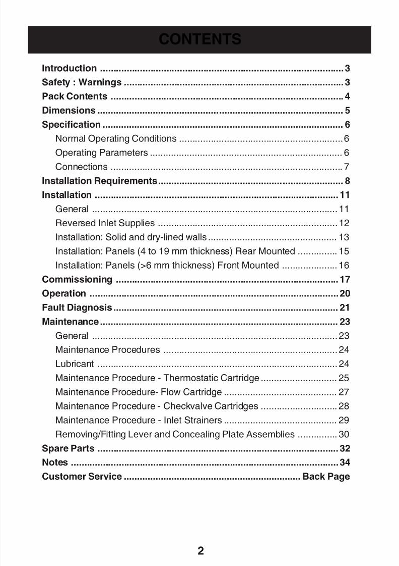
CONTENTS
Introduction ............................................................................................3
Safety : Warnings ................................................................................... 3
Pack Contents ........................................................................................ 4Dimensions ............................................................................................. 5
Specification ........................................................................................... 6
Normal Operating Conditions ..............................................................6
Operating Parameters ......................................................................... 6
Connections ........................................................................................ 7
Installation Requirements...................................................................... 8
Installation ............................................................................................ 11General ............................................................................................. 11
Reversed Inlet Supplies ....................................................................12
Installation: Solid and dry-lined walls ................................................. 13
Installation: Panels (4 to 19 mm thickness) Rear Mounted ............... 15
Installation: Panels (>6 mm thickness) Front Mounted ..................... 16
Commissioning .................................................................................... 17
Operation ..............................................................................................20Fault Diagnosis ..................................................................................... 21
Maintenance.......................................................................................... 23
General ............................................................................................. 23
Maintenance Procedures .................................................................. 24
Lubricant ........................................................................................... 24
Maintenance Procedure - Thermostatic Cartridge ............................. 25
Maintenance Procedure- Flow Cartridge ........................................... 27Maintenance Procedure - Checkvalve Cartridges ............................. 28
Maintenance Procedure - Inlet Strainers ........................................... 29
Removing/Fitting Lever and Concealing Plate Assemblies ............... 30
Spare Parts ........................................................................................... 32
Notes .....................................................................................................34
Customer Service ................................................................... Back Page
8/8/2019 Mira Aquations Shower Valve
http://slidepdf.com/reader/full/mira-aquations-shower-valve 3/363
This Aquations Thermostatic Shower Control is precision engineered and should
give continued safe and controlled performance, provided:
1. It is installed, commissioned, operated and maintained in accordance with
manufacturers recommendations.
2. Periodic attention is given, when necessary, to maintain the product in goodfunctional order.
The function of a thermostatic mixing valve is to deliver water consistently at a safe
temperature. In keeping with every other mechanism, it cannot be considered as
functionally infallible and as such, cannot totally replace a supervisor’s vigilance
where that is necessary. Provided it is installed, commissioned, operated and
maintained within manufacturers recommendations, the risk of failure, if not
eliminated, is reduced to the minimum achievable.
The Mira Aquations Thermostatic mixing valve is specified to meet the highest
standards of safety, comfort and economy as demanded by todays users. The Mira
Aquations is designed, manufactured and supported in accordance with accredited
BS EN ISO 9001:1994 Quality Systems.This Manual covers all Mira Aquations Thermostatic mixing valves manufactured
from April 2003.
The Mira Aquations Shower Valve is a thermostatic shower control with independent
selection for temperature and spray force and is suitable for connection to concealed
pipework.
Mira Aquations Built-in, with 15 mm compression inlet/outlet connections.
Supplied hot-left, cold-right but can be reversed.
INTRODUCTION
SAFETY : WARNINGS
If you experience any difficulty with the installation or operation of your new shower
control, then please refer to ‘Fault Diagnosis’, before contacting Kohler Mira Limited.
Our telephone and fax numbers can be found on the back cover of this guide.
8/8/2019 Mira Aquations Shower Valve
http://slidepdf.com/reader/full/mira-aquations-shower-valve 4/364
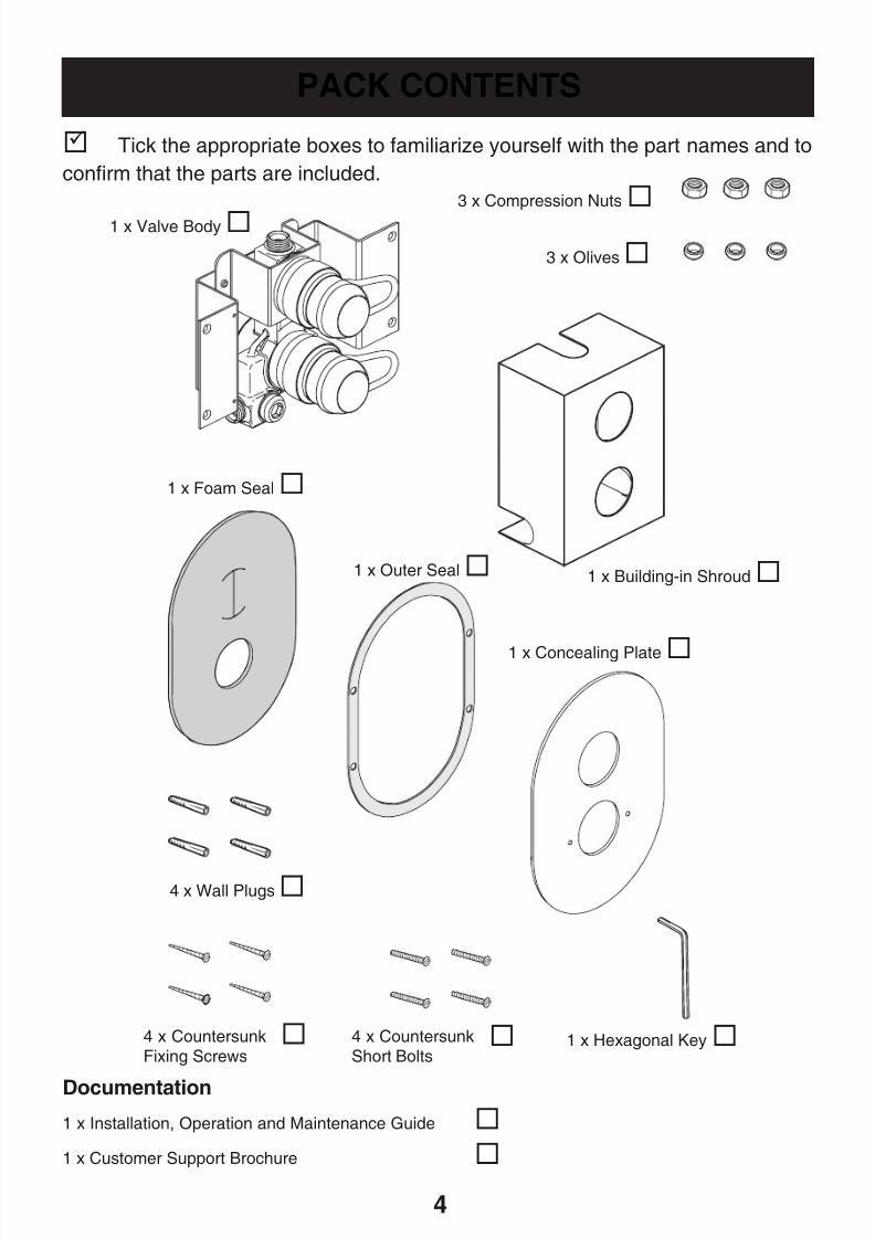
PACK CONTENTS
Documentation
1 x Installation, Operation and Maintenance Guide
1 x Customer Support Brochure
1 x Concealing Plate
3 x Compression Nuts
3 x Olives
1 x Foam Seal
1 x Building-in Shroud
1 x Valve Body
1 x Outer Seal
4 x Wall Plugs
4 x CountersunkFixing Screws
Tick the appropriate boxes to familiarize yourself with the part names and to
confirm that the parts are included.
4 x CountersunkShort Bolts
1 x Hexagonal Key
8/8/2019 Mira Aquations Shower Valve
http://slidepdf.com/reader/full/mira-aquations-shower-valve 5/365
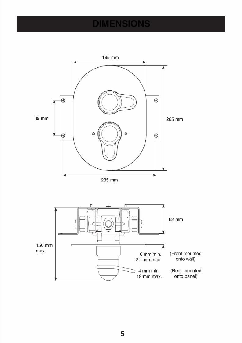
DIMENSIONSDIMENSIONS
185 mm
265 mm89 mm
235 mm
6 mm min.
21 mm max.
150 mmmax.
62 mm
4 mm min.19 mm max.
(Rear mountedonto panel)
(Front mountedonto wall)
8/8/2019 Mira Aquations Shower Valve
http://slidepdf.com/reader/full/mira-aquations-shower-valve 6/366
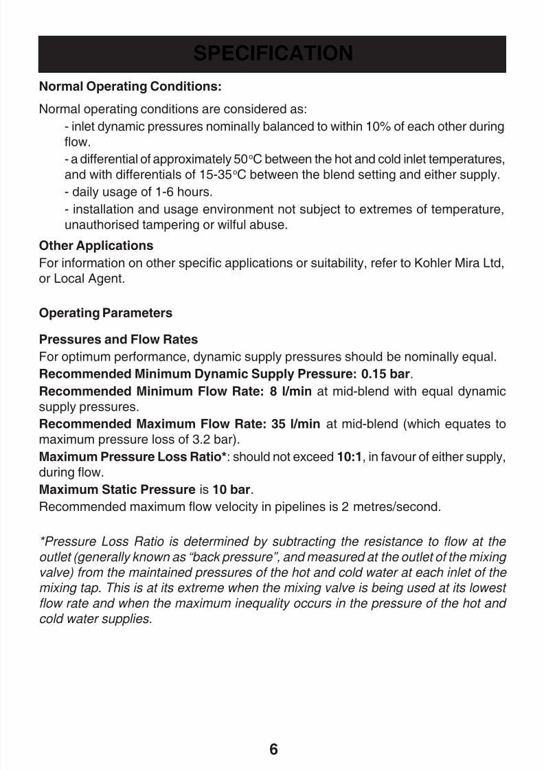
SPECIFICATION
Normal Operating Conditions:
Normal operating conditions are considered as:
- inlet dynamic pressures nominally balanced to within 10% of each other during
flow.
- a differential of approximately 50oC between the hot and cold inlet temperatures,
and with differentials of 15-35oC between the blend setting and either supply.
- daily usage of 1-6 hours.
- installation and usage environment not subject to extremes of temperature,
unauthorised tampering or wilful abuse.
Other Applications
For information on other specific applications or suitability, refer to Kohler Mira Ltd,
or Local Agent.
Operating Parameters
Pressures and Flow Rates
For optimum performance, dynamic supply pressures should be nominally equal.
Recommended Minimum Dynamic Supply Pressure: 0.15 bar.
Recommended Minimum Flow Rate: 8 l/min at mid-blend with equal dynamic
supply pressures.Recommended Maximum Flow Rate: 35 l/min at mid-blend (which equates to
maximum pressure loss of 3.2 bar).
Maximum Pressure Loss Ratio*: should not exceed 10:1, in favour of either supply,
during flow.
Maximum Static Pressure is 10 bar.
Recommended maximum flow velocity in pipelines is 2 metres/second.
*Pressure Loss Ratio is determined by subtracting the resistance to flow at the outlet (generally known as “back pressure”, and measured at the outlet of the mixing
valve) from the maintained pressures of the hot and cold water at each inlet of the mixing tap. This is at its extreme when the mixing valve is being used at its lowest
flow rate and when the maximum inequality occurs in the pressure of the hot and
cold water supplies.
8/8/2019 Mira Aquations Shower Valve
http://slidepdf.com/reader/full/mira-aquations-shower-valve 7/367
Temperatures
Optimum performance is obtained when temperature differentials of 20°C or more
exist between blend and either supply. Blend control accuracy will begin to diminish
at temperature differentials below 12°C.
Blend Temperature Range: Between ambient cold and approximately 60°C,
according to hot water supply temperature.Thermostatic Control Range: Approximately 25-60°C.
Optimum Thermostatic Control Range: 30-50°C.
Recommended Minimum Cold Water Supply Temperature: 1°C.
Recommended Maximum Hot Water Supply Temperature: 85°C.
Note! The shower control can accept temporary temperature excursions above
85°C without damage, however operation at such elevated supply temperatures is
not recommended. For reasons of general safety, hot water storage temperatures
should ideally be maintained at between 60-65°C where serving ablutionaryapplications. Minimum temperature differential between hot and outlet temperature:
10°C.
Note! The operating parameters above are for the valve only. The operating
parameters for the outlet fittings should also be taken into consideration when installing
this product.
Connections
The shower control connections are all 15 mm compression (nuts and olives areprovided).
Hot (H) and Cold (C) inlets are clearly marked for the shower control and must be
connected as described in the Installation section.
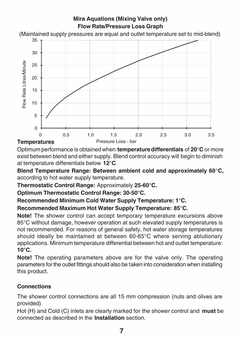
Mira Aquations (Mixing Valve only)
Flow Rate/Pressure Loss Graph
(Maintained supply pressures are equal and outlet temperature set to mid-blend)
Pressure Loss - bar
F l o w
R a t e L i t r e s / M i n u t e
0
10
20
30
35
0 0.5 1.0 1.5 3.02.52.0 3.5
25
15
5
8/8/2019 Mira Aquations Shower Valve
http://slidepdf.com/reader/full/mira-aquations-shower-valve 8/36
8/8/2019 Mira Aquations Shower Valve
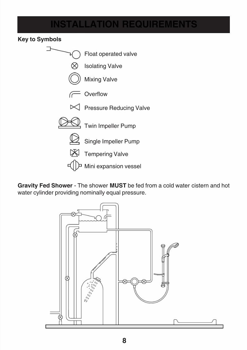
http://slidepdf.com/reader/full/mira-aquations-shower-valve 9/369
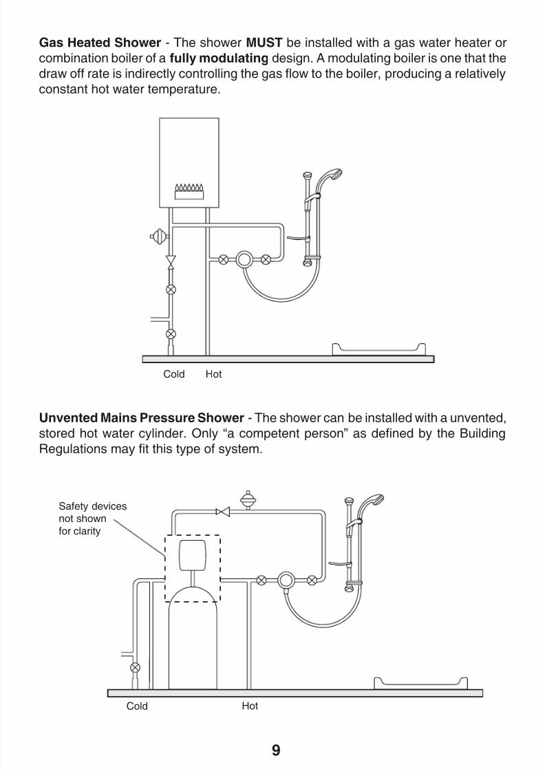
Unvented Mains Pressure Shower - The shower can be installed with a unvented,
stored hot water cylinder. Only “a competent person” as defined by the Building
Regulations may fit this type of system.
Gas Heated Shower - The shower MUST be installed with a gas water heater or
combination boiler of a fully modulating design. A modulating boiler is one that the
draw off rate is indirectly controlling the gas flow to the boiler, producing a relatively
constant hot water temperature.
Cold Hot
Safety devicesnot shown
for clarity
HotCold
8/8/2019 Mira Aquations Shower Valve
http://slidepdf.com/reader/full/mira-aquations-shower-valve 10/3610
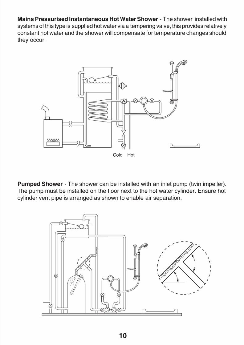
Mains Pressurised Instantaneous Hot Water Shower - The shower installed with
systems of this type is supplied hot water via a tempering valve, this provides relatively
constant hot water and the shower will compensate for temperature changes should
they occur.
Pumped Shower - The shower can be installed with an inlet pump (twin impeller).
The pump must be installed on the floor next to the hot water cylinder. Ensure hot
cylinder vent pipe is arranged as shown to enable air separation.
Cold Hot
8/8/2019 Mira Aquations Shower Valve
http://slidepdf.com/reader/full/mira-aquations-shower-valve 11/3611
INSTALLATION
General
Installation must be carried out in accordance with these instructions, and must be
conducted by designated, qualified and competent personnel.
The installation must comply with the “Water Supply Regulations 1999(Water Fittings)” or any particular regulations and practices, specified by the localwater company or water undertakers.
1. Before commencing, make sure that the installation conditions comply with the
information given in SPECIFICATION.
2. Care must be taken during installation to prevent any risk of injury or damage.
3. The mixing valve should be positioned for easy access during use and
maintenance. All routine maintenance procedures can be conducted with the
mixing valve body in place (except for strainer and checkvalve access). For allmodels, allow a minimum 80 mm clearance in front of the temperature control
to enable removal of the serviceable parts during maintenance.
4. The use of supply-line or zone strainers will reduce the need to remove debris
at each mixing valve point. The recommended maximum mesh aperture
dimension for such strainers is 0.5 mm.
5. Pipework should be rigidly supported.
6. Pipework dead-legs should be kept to a minimum. The mixed water outlet piping
should not exceed 2 m and the overall length from the hot water circuit to the
discharge point should not exceed 5 m.
7. Supply pipework layout should be arranged to minimise the effect of other outlet
usage upon the maintained pressures at the mixing valve inlets.
8. Inlet and outlet threaded joint connections should be made with PTFE tape or
liquid sealant. Oil-based, non-setting jointing compounds should not be used.
9. To eliminate pipe debris it is essential that supply pipes are thoroughly flushed
through before connection to the mixing valve.
The Mira Aquations shower control can be built into solid, dry-lined, stud partition ordry partition wall structures. All plumbing connections are 15 mm compression.
A building-in shroud is supplied, which can provide a depth reference when chasing
out the wall surface and also protects the shower control during plastering.
8/8/2019 Mira Aquations Shower Valve
http://slidepdf.com/reader/full/mira-aquations-shower-valve 12/3612
Reversed Inlet Supplies
It is essential the inlet supplies correspond with the red and blue markings on the
thermostatic cartridge fitted in the Mira Aquations in order to operate correctly. The
shower control is supplied with the inlet connections configured hot-left, cold-right.
If the existing hot and cold pipework make this configuration inconvenient the cartridge
inlets can be reversed.
The connections can be altered by rotating the thermostatic cartridge through 180°,
before or after installation.
1. If the mixing valve body has already been installed, isolate the supplies to the
mixing valve, and turn on the flow control. This will release the pressure and
assist in draining the residual water.
2. Remove the knob and cover assemblies. Refer to Removing/Fitting Knob
and Cover Assemblies for detailed instructions.3. With the removal clip still in place, unscrew the head nut using a 35 mm A/F
wrench; this will begin to draw the thermostatic cartridge out of the body.
Note! Some residual water may be released. Pull the thermostatic cartridge
free of the valve body.
4. Rotate the thermostatic cartridge through 180o and carefully push the cartridge
back into the valve body, checking that the 2 cartridge inlet port seals remain in
place, and locate cartridge lugs into the body slots.
Note! The red and blue markings on the cartridge will now not correspond with
the body markings, so to avoid future confusion remove the red and blue stickers
from the valve body.
5. Carefully align and then tighten the head nut; do not overtighten.
6. Complete the INSTALLATION, if appropriate.
7. If the mixing valve body has already been installed, restore hot and cold supplies
and check for any leaks.8. Refit the foam seal, concealing plate and secure in position with the locknuts.
Ensure the foam seal remains in position as the locknuts are screwed back into
position. Refit the locknut trims and lever assemblies. (Refer to Removing/
Fitting Lever and Concealing Plate Assemblies).
9. The maximum temperature may now need resetting; check, and if necessary
refer to COMMISSIONING.
8/8/2019 Mira Aquations Shower Valve
http://slidepdf.com/reader/full/mira-aquations-shower-valve 13/3613
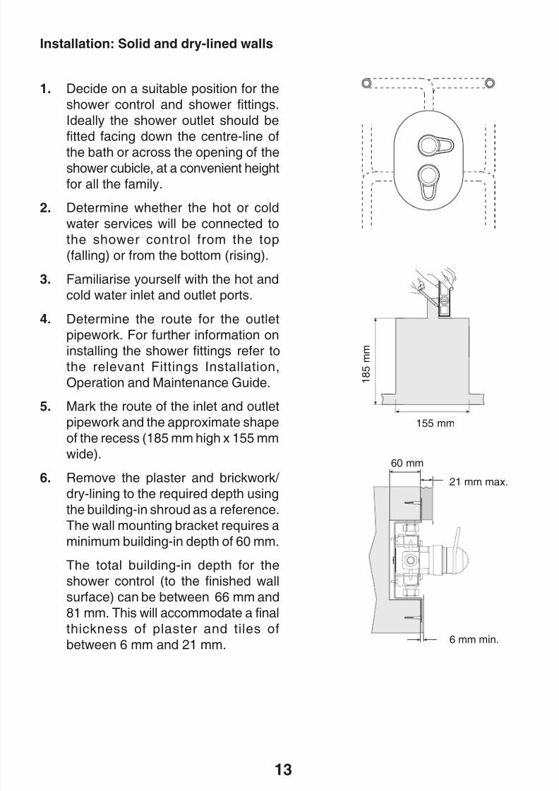
1. Decide on a suitable position for the
shower control and shower fittings.
Ideally the shower outlet should be
fitted facing down the centre-line ofthe bath or across the opening of the
shower cubicle, at a convenient height
for all the family.
2. Determine whether the hot or cold
water services will be connected to
the shower control from the top
(falling) or from the bottom (rising).
3. Familiarise yourself with the hot andcold water inlet and outlet ports.
4. Determine the route for the outlet
pipework. For further information on
installing the shower fittings refer to
the relevant Fittings Installation,
Operation and Maintenance Guide.
5. Mark the route of the inlet and outlet
pipework and the approximate shape
of the recess (185 mm high x 155 mm
wide).
6. Remove the plaster and brickwork/
dry-lining to the required depth using
the building-in shroud as a reference.
The wall mounting bracket requires a
minimum building-in depth of 60 mm.
The total building-in depth for the
shower control (to the finished wall
surface) can be between 66 mm and
81 mm. This will accommodate a final
thickness of plaster and tiles of
between 6 mm and 21 mm.
Installation: Solid and dry-lined walls
155 mm
1 8 5 m m
60 mm
21 mm max.
6 mm min.
8/8/2019 Mira Aquations Shower Valve
http://slidepdf.com/reader/full/mira-aquations-shower-valve 14/3614
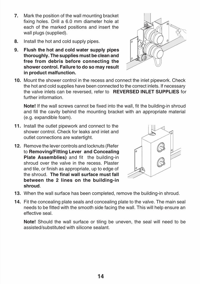
11. Install the outlet pipework and connect to the
shower control. Check for leaks and inlet and
outlet connections are watertight.
12. Remove the lever controls and locknuts (Refer
to Removing/Fitting Lever and Concealing
Plate Assemblies) and fit the building-in
shroud over the valve in the recess. Plaster
and tile, or finish as appropriate, up to edge of
the shroud. The final wall surface must fall
between the 2 lines on the building-in
shroud.
7. Mark the position of the wall mounting bracket
fixing holes. Drill a 6.0 mm diameter hole at
each of the marked positions and insert the
wall plugs (supplied).
8. Install the hot and cold supply pipes.
9. Flush the hot and cold water supply pipesthoroughly. The supplies must be clean and
free from debris before connecting the
shower control. Failure to do so may result
in product malfunction.
10. Mount the shower control in the recess and connect the inlet pipework. Check
the hot and cold supplies have been connected to the correct inlets. If necessary
the valve inlets can be reversed, refer to REVERSED INLET SUPPLIES for
further information.Note! If the wall screws cannot be fixed into the wall, fit the building-in shroud
and fill the cavity behind the mounting bracket with an appropriate material
(e.g. expandible foam).
13. When the wall surface has been completed, remove the building-in shroud.
14. Fit the concealing plate seals and concealing plate to the valve. The main seal
needs to be fitted with the smooth side facing the wall. This will help ensure an
effective seal.
Note! Should the wall surface or tiling be uneven, the seal will need to be
assisted/substituted with silicone sealant.
8/8/2019 Mira Aquations Shower Valve
http://slidepdf.com/reader/full/mira-aquations-shower-valve 15/3615
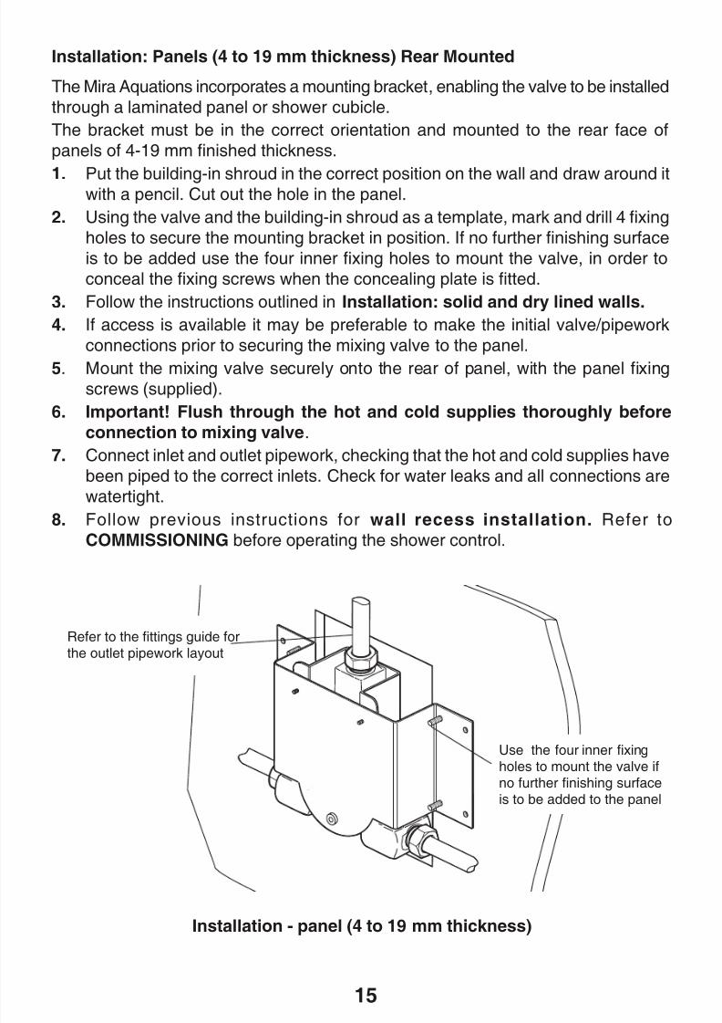
Installation: Panels (4 to 19 mm thickness) Rear Mounted
The Mira Aquations incorporates a mounting bracket, enabling the valve to be installed
through a laminated panel or shower cubicle.
The bracket must be in the correct orientation and mounted to the rear face of
panels of 4-19 mm finished thickness.
1. Put the building-in shroud in the correct position on the wall and draw around itwith a pencil. Cut out the hole in the panel.
2. Using the valve and the building-in shroud as a template, mark and drill 4 fixing
holes to secure the mounting bracket in position. If no further finishing surface
is to be added use the four inner fixing holes to mount the valve, in order to
conceal the fixing screws when the concealing plate is fitted.
3. Follow the instructions outlined in Installation: solid and dry lined walls.
4. If access is available it may be preferable to make the initial valve/pipework
connections prior to securing the mixing valve to the panel.
5. Mount the mixing valve securely onto the rear of panel, with the panel fixing
screws (supplied).
6. Important! Flush through the hot and cold supplies thoroughly before
connection to mixing valve.
7. Connect inlet and outlet pipework, checking that the hot and cold supplies have
been piped to the correct inlets. Check for water leaks and all connections are
watertight.
8. Follow previous instructions for wall recess installation. Refer to
COMMISSIONING before operating the shower control.
Installation - panel (4 to 19 mm thickness)
Refer to the fittings guide forthe outlet pipework layout
Use the four inner fixingholes to mount the valve ifno further finishing surfaceis to be added to the panel
8/8/2019 Mira Aquations Shower Valve
http://slidepdf.com/reader/full/mira-aquations-shower-valve 16/3616
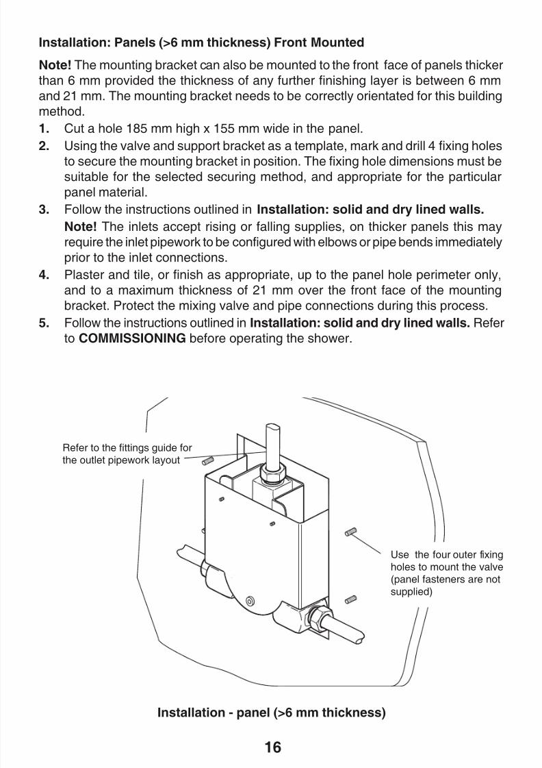
Installation: Panels (>6 mm thickness) Front Mounted
Note! The mounting bracket can also be mounted to the front face of panels thicker
than 6 mm provided the thickness of any further finishing layer is between 6 mm
and 21 mm. The mounting bracket needs to be correctly orientated for this building
method.
1. Cut a hole 185 mm high x 155 mm wide in the panel.2. Using the valve and support bracket as a template, mark and drill 4 fixing holes
to secure the mounting bracket in position. The fixing hole dimensions must be
suitable for the selected securing method, and appropriate for the particular
panel material.
3. Follow the instructions outlined in Installation: solid and dry lined walls.
Note! The inlets accept rising or falling supplies, on thicker panels this may
require the inlet pipework to be configured with elbows or pipe bends immediately
prior to the inlet connections.
4. Plaster and tile, or finish as appropriate, up to the panel hole perimeter only,
and to a maximum thickness of 21 mm over the front face of the mounting
bracket. Protect the mixing valve and pipe connections during this process.
5. Follow the instructions outlined in Installation: solid and dry lined walls. Refer
to COMMISSIONING before operating the shower.
Installation - panel (>6 mm thickness)
Refer to the fittings guide forthe outlet pipework layout
Use the four outer fixingholes to mount the valve(panel fasteners are notsupplied)
8/8/2019 Mira Aquations Shower Valve
http://slidepdf.com/reader/full/mira-aquations-shower-valve 17/3617
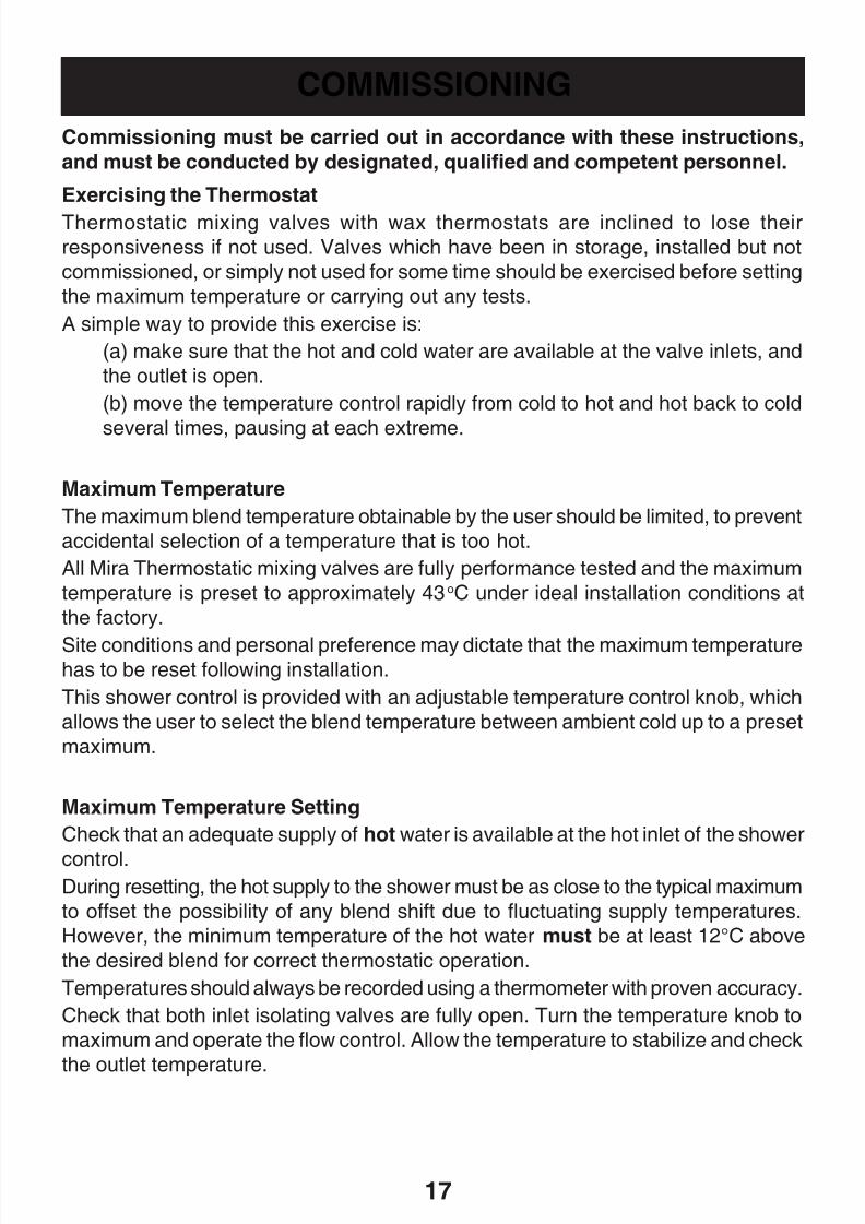
COMMISSIONING
Commissioning must be carried out in accordance with these instructions,
and must be conducted by designated, qualified and competent personnel.
Exercising the Thermostat
Thermostatic mixing valves with wax thermostats are inclined to lose theirresponsiveness if not used. Valves which have been in storage, installed but not
commissioned, or simply not used for some time should be exercised before setting
the maximum temperature or carrying out any tests.
A simple way to provide this exercise is:
(a) make sure that the hot and cold water are available at the valve inlets, and
the outlet is open.
(b) move the temperature control rapidly from cold to hot and hot back to cold
several times, pausing at each extreme.
Maximum Temperature
The maximum blend temperature obtainable by the user should be limited, to prevent
accidental selection of a temperature that is too hot.
All Mira Thermostatic mixing valves are fully performance tested and the maximum
temperature is preset to approximately 43oC under ideal installation conditions at
the factory.
Site conditions and personal preference may dictate that the maximum temperaturehas to be reset following installation.
This shower control is provided with an adjustable temperature control knob, which
allows the user to select the blend temperature between ambient cold up to a preset
maximum.
Maximum Temperature Setting
Check that an adequate supply of hot water is available at the hot inlet of the shower
control.During resetting, the hot supply to the shower must be as close to the typical maximum
to offset the possibility of any blend shift due to fluctuating supply temperatures.
However, the minimum temperature of the hot water must be at least 12°C above
the desired blend for correct thermostatic operation.
Temperatures should always be recorded using a thermometer with proven accuracy.
Check that both inlet isolating valves are fully open. Turn the temperature knob to
maximum and operate the flow control. Allow the temperature to stabilize and check
the outlet temperature.
8/8/2019 Mira Aquations Shower Valve
http://slidepdf.com/reader/full/mira-aquations-shower-valve 18/3618
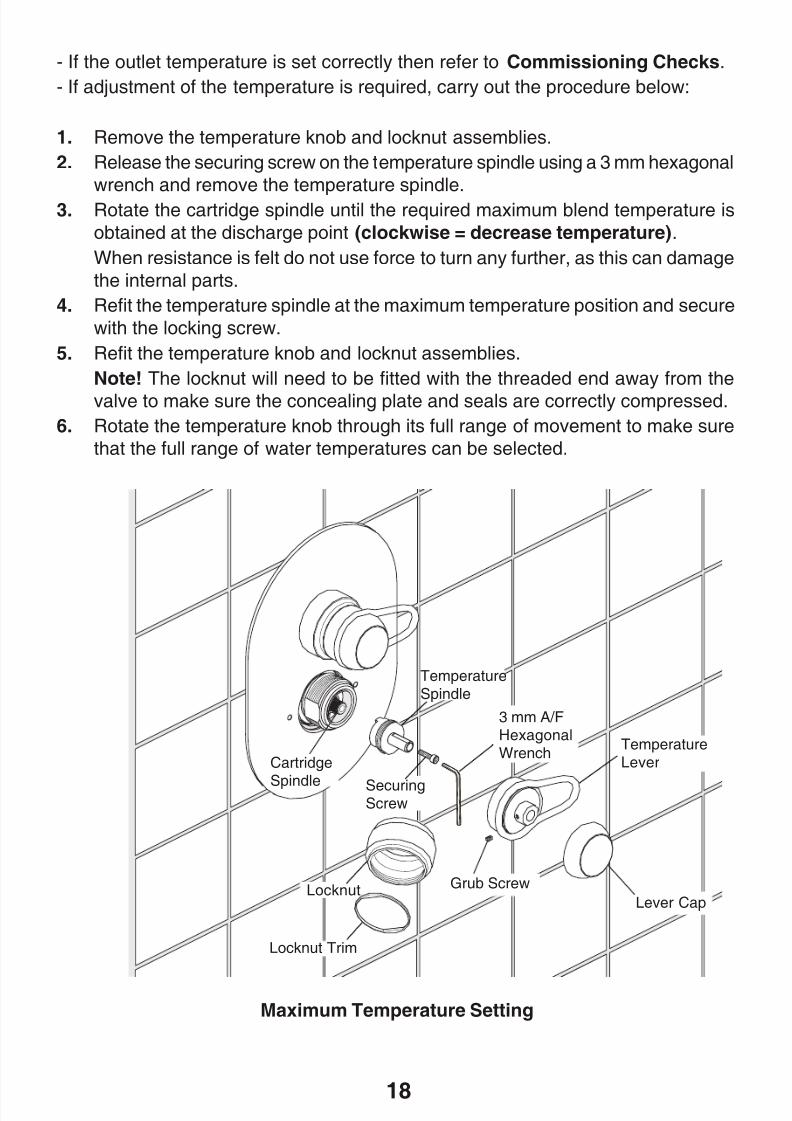
Maximum Temperature Setting
- If the outlet temperature is set correctly then refer to Commissioning Checks.
- If adjustment of the temperature is required, carry out the procedure below:
1. Remove the temperature knob and locknut assemblies.
2. Release the securing screw on the temperature spindle using a 3 mm hexagonal
wrench and remove the temperature spindle.
3. Rotate the cartridge spindle until the required maximum blend temperature is
obtained at the discharge point (clockwise = decrease temperature).
When resistance is felt do not use force to turn any further, as this can damage
the internal parts.
4. Refit the temperature spindle at the maximum temperature position and secure
with the locking screw.
5. Refit the temperature knob and locknut assemblies.
Note! The locknut will need to be fitted with the threaded end away from the
valve to make sure the concealing plate and seals are correctly compressed.
6. Rotate the temperature knob through its full range of movement to make sure
that the full range of water temperatures can be selected.
TemperatureLever
TemperatureSpindle
Cartridge
Spindle SecuringScrew
3 mm A/FHexagonalWrench
Lever CapLocknut
Locknut Trim
Grub Screw
8/8/2019 Mira Aquations Shower Valve
http://slidepdf.com/reader/full/mira-aquations-shower-valve 19/3619
Commissioning Checks
(Temperatures should always be recorded with a thermometer with proven accuracy).
1. Check inlet pipework temperatures for correct function of checkvalves i.e. that
hot water does not cross flow into the cold supply and vice versa.
2. Check that the supply pressures are within the operating pressures for the
valve.
3. Make sure that all connections and mixer body are water tight.
4. Exercise the thermostat.
(a) make sure that the hot and cold water are available at the valve inlets, and
the outlet is open.
(b) move the temperature control rapidly from cold to hot and hot back to cold
several times, pausing at each extreme.
5. Adjust the temperature of the mixed water in accordance with the instructions
(refer to Maximum Temperature Settings).
6. Operate the outlet flow control and check:
(a) Flow rate is sufficient for the purpose.
(b) Temperature(s) obtainable are acceptable.
8/8/2019 Mira Aquations Shower Valve
http://slidepdf.com/reader/full/mira-aquations-shower-valve 20/3620
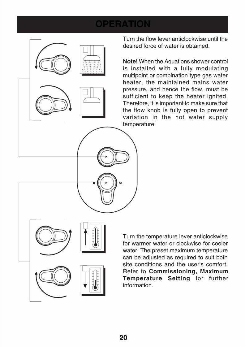
OPERATION
Turn the temperature lever anticlockwise
for warmer water or clockwise for coolerwater. The preset maximum temperature
can be adjusted as required to suit both
site conditions and the user's comfort.
Refer to Commissioning, Maximum
Temperature Setting for further
information.
Turn the flow lever anticlockwise until the
desired force of water is obtained.
Note! When the Aquations shower controlis installed with a fully modulating
multipoint or combination type gas water
heater, the maintained mains water
pressure, and hence the flow, must be
sufficient to keep the heater ignited.
Therefore, it is important to make sure that
the flow knob is fully open to prevent
variation in the hot water supply
temperature.
8/8/2019 Mira Aquations Shower Valve
http://slidepdf.com/reader/full/mira-aquations-shower-valve 21/3621
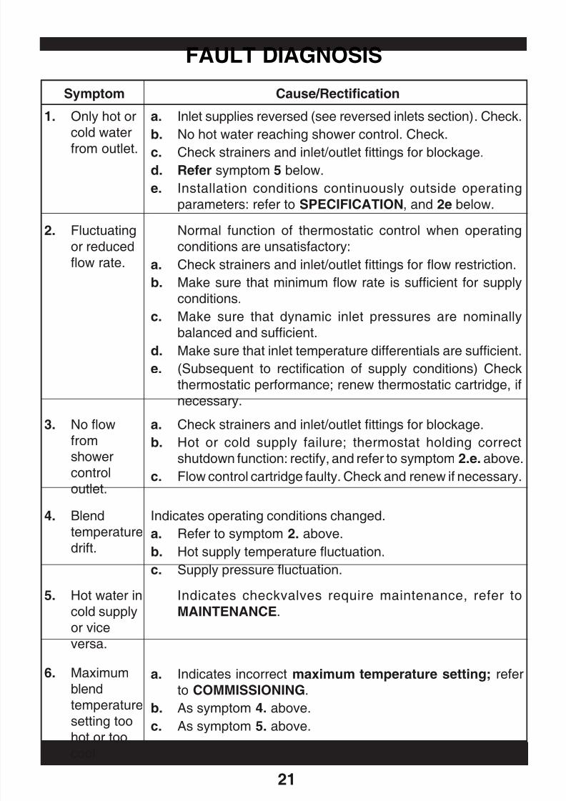
FAULT DIAGNOSIS
Symptom Cause/Rectification
Normal function of thermostatic control when operating
conditions are unsatisfactory:
a. Check strainers and inlet/outlet fittings for flow restriction.
b. Make sure that minimum flow rate is sufficient for supplyconditions.
c. Make sure that dynamic inlet pressures are nominally
balanced and sufficient.
d. Make sure that inlet temperature differentials are sufficient.
e. (Subsequent to rectification of supply conditions) Check
thermostatic performance; renew thermostatic cartridge, if
necessary.
2. Fluctuating
or reduced
flow rate.
3. No flowfromshower
control
outlet.
4. Blend
temperature
drift.
Indicates operating conditions changed.
a. Refer to symptom 2. above.
b. Hot supply temperature fluctuation.
c. Supply pressure fluctuation.
a. Check strainers and inlet/outlet fittings for blockage.b. Hot or cold supply failure; thermostat holding correct
shutdown function: rectify, and refer to symptom 2.e. above.
c. Flow control cartridge faulty. Check and renew if necessary.
a. Inlet supplies reversed (see reversed inlets section). Check.
b. No hot water reaching shower control. Check.c. Check strainers and inlet/outlet fittings for blockage.
d. Refer symptom 5 below.
e. Installation conditions continuously outside operating
parameters: refer to SPECIFICATION, and 2e below.
1. Only hot or
cold water
from outlet.
5. Hot water in
cold supply
or vice
versa.
Indicates checkvalves require maintenance, refer to
MAINTENANCE.
6. Maximum
blend
temperaturesetting too
hot or too
cool.
a. Indicates incorrect maximum temperature setting; refer
to COMMISSIONING.
b. As symptom 4. above.
c. As symptom 5. above.
8/8/2019 Mira Aquations Shower Valve
http://slidepdf.com/reader/full/mira-aquations-shower-valve 22/3622
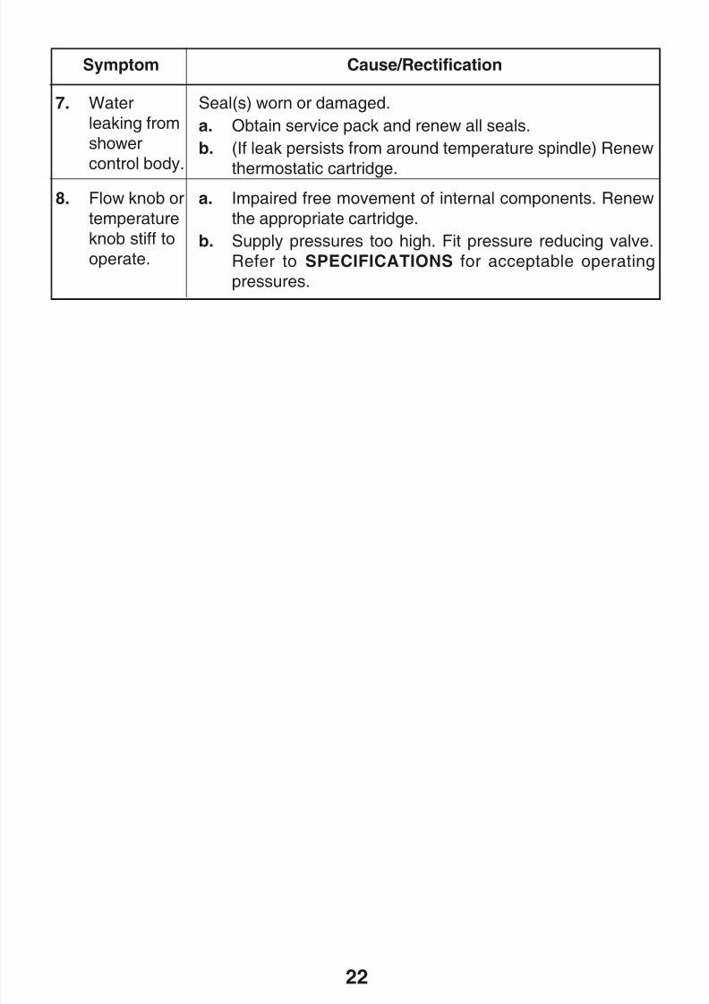
Symptom Cause/Rectification
7. Water
leaking from
shower
control body.
Seal(s) worn or damaged.
a. Obtain service pack and renew all seals.
b. (If leak persists from around temperature spindle) Renew
thermostatic cartridge.8. Flow knob or
temperature
knob stiff to
operate.
a. Impaired free movement of internal components. Renew
the appropriate cartridge.
b. Supply pressures too high. Fit pressure reducing valve.
Refer to SPECIFICATIONS for acceptable operating
pressures.
8/8/2019 Mira Aquations Shower Valve
http://slidepdf.com/reader/full/mira-aquations-shower-valve 23/3623
MAINTENANCE
General
1. The maintenance of this product must be carried out in accordance with
instructions given in this Manual, and must be conducted by designated, qualified
and competent personnel.
2. Mira products are precision-engineered and should give continued superior and
safe performance, provided:
- They are installed, commissioned, operated and maintained in accordance
with the recommendations stated in this Product Manual.
- Periodic attention is given as necessary to maintain the product and its
associated installation components in good functional order. Guidelines are
given below.
3. The use of main supply-line or zone strainers (recommended maximum meshaperture dimension is 0.5 mm) will reduce the need to remove debris at each
mixing valve point.
The designed minimum service life of all cartridges used in Mira products is 5 years
providing the Mira Aquations is operated with the recommended operating conditions
and within the recommended operating parameters. However, when supply conditions
and/or usage patterns do not conform to the recommended operating parameters
and/or the recommended operating conditions, the cartridge and other critical partsmay need to be replaced more frequently (‘recommended operating conditions’ and
‘recommended parameters’ are defined in section: ‘Specifications’ under the
headings of ‘Normal Operating Conditions’ and ‘Operating Parameters’).
8/8/2019 Mira Aquations Shower Valve
http://slidepdf.com/reader/full/mira-aquations-shower-valve 24/3624
Maintenance Procedures
Maintenance must be carried out in accordance with these instructions, and must
be conducted by designated, qualified and competent personnel.
This mixing valve is designed for minimal maintenance under conditions of normal
use.
External surfaces may be wiped clean with a soft cloth, and if necessary, a mildwashing-up type detergent or soap solution can be used.
Warning! Many household and industrial cleaning products contain mild abrasives
and chemical concentrates, and should not be used on polished, chromed or plastic
surfaces.
Should an internal malfunction occur then this will probably require replacement of
parts.
Components are precision-made, so care must be taken while servicing to avoid
damage.
When ordering spare parts, please state product type, i.e. Mira Aquations, and
identify part name and number (refer to PARTS LIST). A Seal pack is available,
containing all the seals that may be necessary for renewal during maintenance or
servicing.
Lubricant
Important! All seals are pre-lubricated. If you need to lubricate the seals, use only
a small amount of silicone-only based lubricants on this product. Do not use oil-based
or other lubricant types as these may cause rapid deterioration of seals.
8/8/2019 Mira Aquations Shower Valve
http://slidepdf.com/reader/full/mira-aquations-shower-valve 25/3625
Maintenance Procedure - Thermostatic Cartridge
Removal
1. Isolate the supplies to the shower control, and open the flow control to release
pressure and to assist the draining of residual water.
2. Remove the lever knobs, locknuts, concealing plate and seals. Do not remove
the temperature spindle.3. With removal clip still in place, unscrew the head nut using a 35 mm A/F wrench.
This will release the headnut and also begin to draw the thermostatic cartridge
out of the shower control body.
Caution! Some residual water may be released.
4. Note which inlet aligns with the hot (marked H and coloured red) lug on cartridge.
5. Pull the thermostatic cartridge free of the shower control body.
Cleaning/Renewal of Parts
6. The interior surface of the shower control body must be clean before refittingthe cartridge. If scale or deposition is present, clean (without thermostatic,
flow and checkvalve cartridges fitted) using a mild proprietary inhibited scale
solvent, e.g. domestic kettle descalent. After descaling, rinse body thoroughly
in clean water before refitting cartridges.
Note! The body interior must be cleaned carefully and not damaged in any
way. Do not use any abrasive material.
7. Cartridges may only be cleaned by flushing through under a jet of clean water
to remove lodged particles. Do not descale. Cartridges are not serviceable,and must not be dismantled.
Cartridges cannot be tested individually, service condition should be assessed
as part of the performance check; refer to Commissioning Checks.
8. When renewing the thermostatic cartridge, retain the temperature spindle,
removal clip and head nut off the displaced unit so they can be fitted to the new
cartridge.
9. Examine all accessible seals for signs of deformation or damage, and if
necessary renew, taking care not to damage seal grooves (a Service Pack is
available, containing all seals and strainer screens that may be necessary forrenewal during maintenance or servicing).
10. Lightly coat all rubber seals with a silicone-only based lubricant to assist
reassembly (see lubricants).
8/8/2019 Mira Aquations Shower Valve
http://slidepdf.com/reader/full/mira-aquations-shower-valve 26/3626
Reassembly
11. Identify which is the hot inlet to the shower control body, and align the
thermostatic cartridge accordingly. Carefully push the thermostatic cartridge
back into the body, checking that the 2 cartridge inlet port seals remain in
place, and locate cartridge lugs into body slots.
12. Carefully align and then tighten the head nut; do not overtighten (max. Torque
2.5 Nm (1.85 lbf ft)). Fit the removal clip to the head nut.
13. Refit the plate and lever assemblies; Refer to Removing/Fitting Lever and
Concealing Plate Assemblies for detailed instructions.
14. Turn off the flow control and restore hot and cold supplies and check for any
leaks.
15. The maximum temperature will now need resetting; refer to COMMISSIONING.
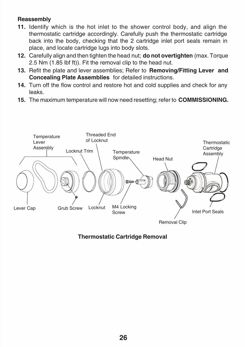
Thermostatic Cartridge Removal
M4 LockingScrew
TemperatureLeverAssembly
Removal Clip
Temperature
Spindle Head Nut
Inlet Port Seals
ThermostaticCartridgeAssembly
Grub Screw
Locknut Trim
Lever Cap Locknut
Threaded End
of Locknut
8/8/2019 Mira Aquations Shower Valve
http://slidepdf.com/reader/full/mira-aquations-shower-valve 27/3627
Maintenance Procedure- Flow Cartridge
Removal
1. Isolate the supplies to the shower control, and open the flow control to release
the pressure and assist draining the residual water.
2. Remove the lever knob and concealing plate assemblies; Refer to
Removing/Fitting Lever and Concealing Plate Assemblies for detailedinstructions.
3. Remove the splined adaptor.
4. Unscrew the flow cartridge anticlockwise and remove.
Caution! Some residual water may be released.
Cleaning/Renewal of Parts
5. The inner surface of the shower control body must be clean before refitting
cartridge. If scale or deposition is present, clean (without thermostatic, flow
and checkvalve cartridges fitted) using a mild proprietary inhibited scalesolvent, e.g. domestic kettle descalent. After descaling, rinse body thoroughly
in clean water before refitting the cartridge.
Note! The shower control body must be cleaned carefully and not damaged in
any way. Do not use any abrasive material.
6. Clean the cartridge by flushing through under a jet of clean water to remove
lodged particles. Do not descale. Cartridges are not serviceable, and must
not be dismantled.
Cartridges cannot be tested individually, service condition should be assessedas part of the performance check; refer to Commissioning Checks.
7. Examine accessible 'O' seals for signs of deformation or damage, and if
necessary renew the cartridge.
8. Lightly coat all seals with a silicone-only based lubricant to assist
reassembling.
Reassembly
9. Check that flow cartridge seals are in place. Align and screw the cartridge into
place.10. Fit the splined adaptor.
11. Refit the lever knob and concealing plate assemblies; Refer to Removing/
Fitting Lever and Concealing Plate Assemblies for detailed instructions.
12. Restore hot and cold supplies and check for leaks.
8/8/2019 Mira Aquations Shower Valve
http://slidepdf.com/reader/full/mira-aquations-shower-valve 28/3628
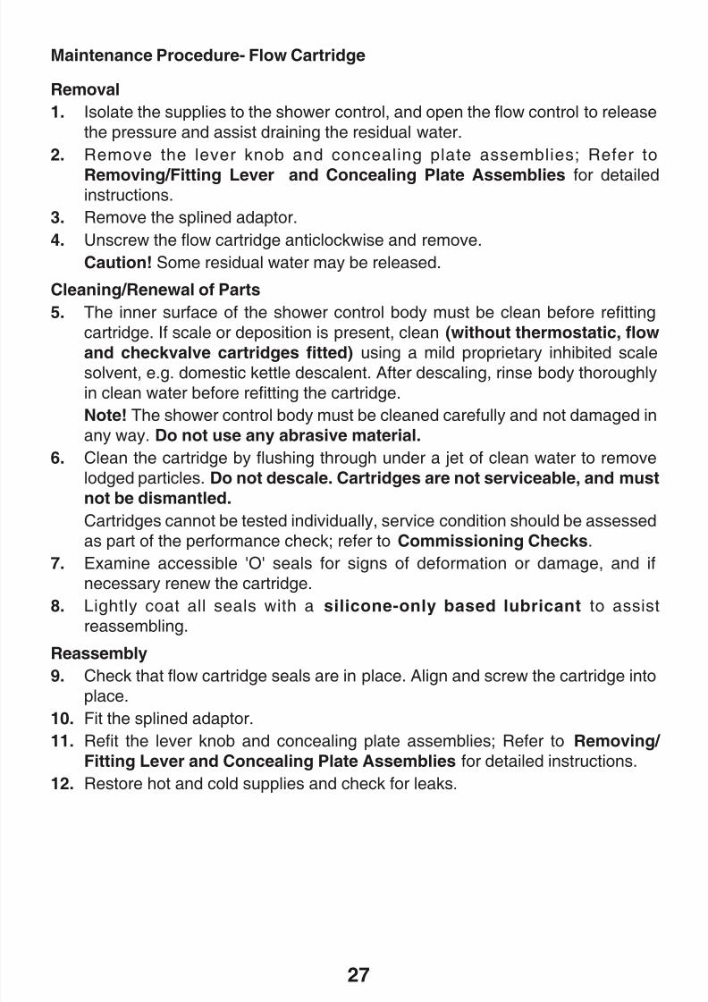
Flow Cartridge Removal
Flow Spindle
Splined Adaptor
Flow Cartridge
Headnut
Locking Screw
Maintenance Procedure - Checkvalve Cartridges
Hot water entering the cold supply, or vice versa, indicates the checkvalve cartridge
needs immediate attention.
1. Isolate the supplies to the shower control, and open the flow control to release
the pressure and assist draining the residual water.
2. Remove the lever knob and concealing plate assemblies; Refer to Removing/ Fitting Lever and Concealing Plate Assemblies for detailed instructions.
3. Undo the cartridge head using a 12 mm A/F wrench and pull the whole cartridge
free from the valve body.
Caution! Some water may be released at this point.
4. The Checkvalve cartridge assemblies may be cleaned by removing the rubber
retainers and inlet strainers, and flushing through under a jet of water to remove
lodged particles. Do not descale. Check if the checkvalve cartridge operates
correctly. If the cartridge is damaged or fails to operate correctly renew.
5. Lightly wipe external seals and threads with a silicone-only based lubricant
to aid refitting.
6. Fit the cartridges and reassemble the shower control following the steps outlined
in Removing/Fitting Lever and Concealing Plate Assemblies. Do not
overtighten the cartridge heads when refitting.
7. Restore the water supplies and check for leaks.
8/8/2019 Mira Aquations Shower Valve
http://slidepdf.com/reader/full/mira-aquations-shower-valve 29/3629
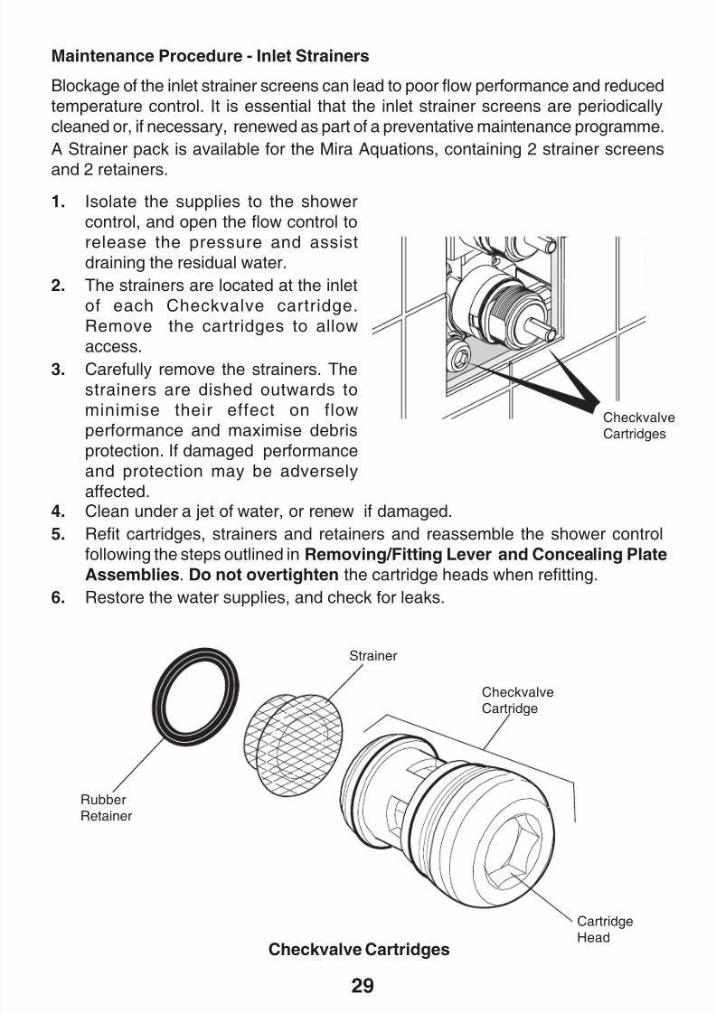
Maintenance Procedure - Inlet Strainers
Blockage of the inlet strainer screens can lead to poor flow performance and reduced
temperature control. It is essential that the inlet strainer screens are periodically
cleaned or, if necessary, renewed as part of a preventative maintenance programme.
A Strainer pack is available for the Mira Aquations, containing 2 strainer screens
and 2 retainers.1. Isolate the supplies to the shower
control, and open the flow control to
release the pressure and assist
draining the residual water.
2. The strainers are located at the inlet
of each Checkvalve cartridge.
Remove the cartridges to allow
access.3. Carefully remove the strainers. The
strainers are dished outwards to
minimise their effect on flow
performance and maximise debris
protection. If damaged performance
and protection may be adversely
affected.
CheckvalveCartridges
Checkvalve Cartridges
CartridgeHead
RubberRetainer
Strainer
Checkvalve
Cartridge
4. Clean under a jet of water, or renew if damaged.
5. Refit cartridges, strainers and retainers and reassemble the shower controlfollowing the steps outlined in Removing/Fitting Lever and Concealing Plate
Assemblies. Do not overtighten the cartridge heads when refitting.
6. Restore the water supplies, and check for leaks.
8/8/2019 Mira Aquations Shower Valve
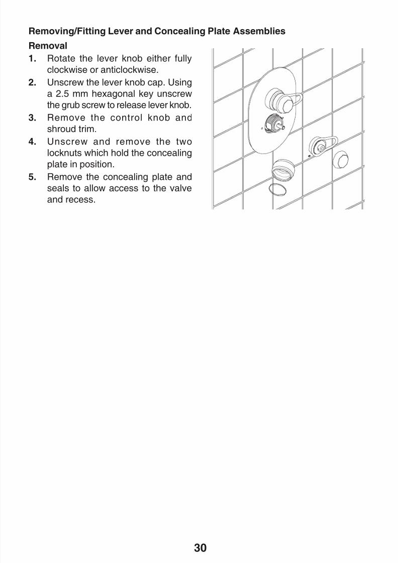
http://slidepdf.com/reader/full/mira-aquations-shower-valve 30/3630
Removal
1. Rotate the lever knob either fully
clockwise or anticlockwise.
2. Unscrew the lever knob cap. Using
a 2.5 mm hexagonal key unscrewthe grub screw to release lever knob.
3. Remove the control knob and
shroud trim.
4. Unscrew and remove the two
locknuts which hold the concealing
plate in position.
5. Remove the concealing plate and
seals to allow access to the valve
and recess.
Removing/Fitting Lever and Concealing Plate Assemblies
8/8/2019 Mira Aquations Shower Valve
http://slidepdf.com/reader/full/mira-aquations-shower-valve 31/3631
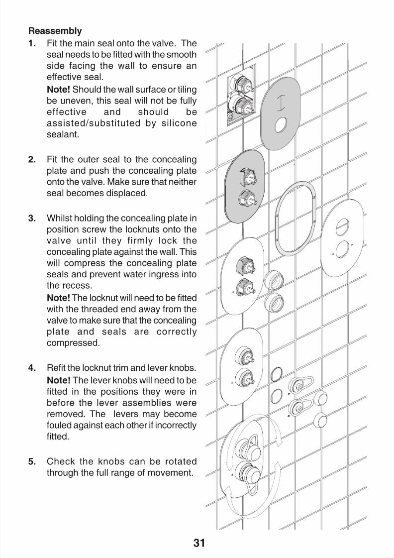
Reassembly
1. Fit the main seal onto the valve. The
seal needs to be fitted with the smooth
side facing the wall to ensure an
effective seal.
Note! Should the wall surface or tiling
be uneven, this seal will not be fullyeffective and should be
assisted/substituted by silicone
sealant.
2. Fit the outer seal to the concealing
plate and push the concealing plate
onto the valve. Make sure that neither
seal becomes displaced.
3. Whilst holding the concealing plate in
position screw the locknuts onto the
valve until they firmly lock the
concealing plate against the wall. This
will compress the concealing plate
seals and prevent water ingress intothe recess.
Note! The locknut will need to be fitted
with the threaded end away from the
valve to make sure that the concealing
plate and seals are correctly
compressed.
4. Refit the locknut trim and lever knobs.
Note! The lever knobs will need to be
fitted in the positions they were inbefore the lever assemblies were
removed. The levers may become
fouled against each other if incorrectly
fitted.
5. Check the knobs can be rotated
through the full range of movement.
8/8/2019 Mira Aquations Shower Valve
http://slidepdf.com/reader/full/mira-aquations-shower-valve 32/3632
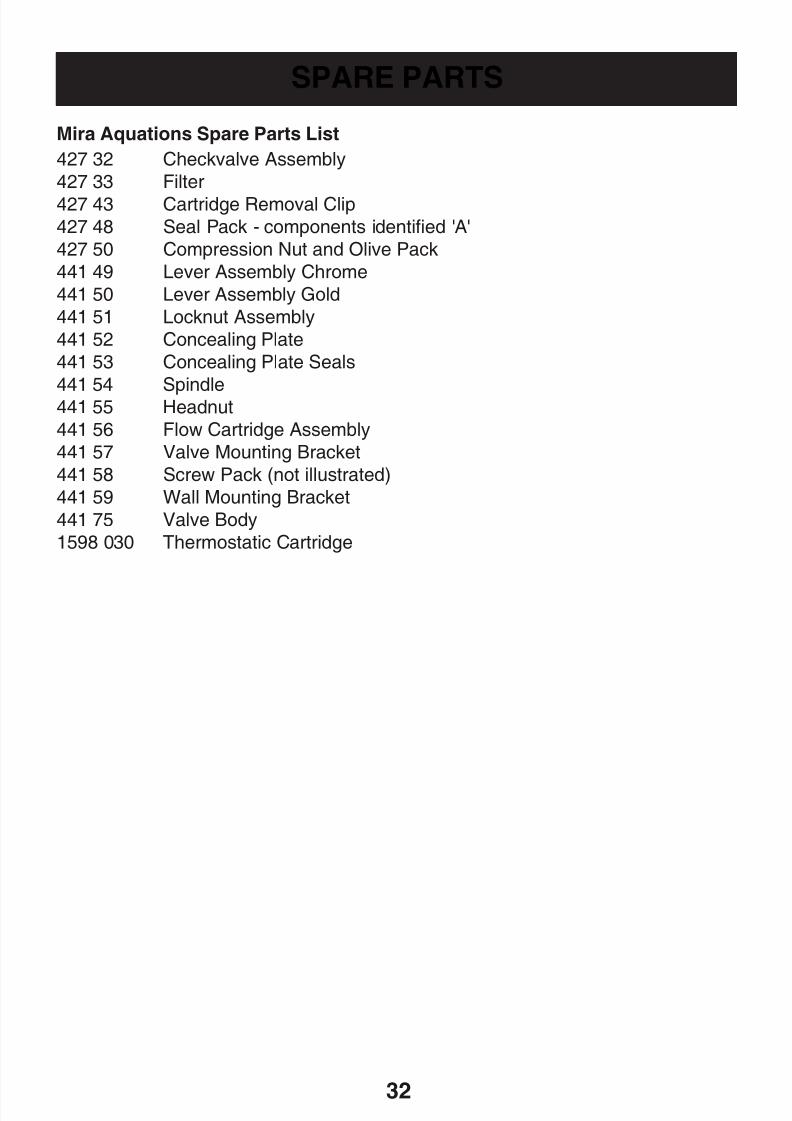
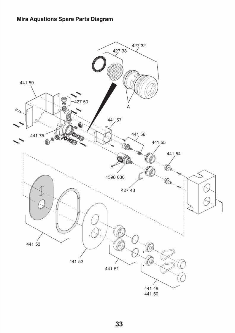
SPARE PARTS
Mira Aquations Spare Parts List
427 32 Checkvalve Assembly
427 33 Filter
427 43 Cartridge Removal Clip
427 48 Seal Pack - components identified 'A'
427 50 Compression Nut and Olive Pack
441 49 Lever Assembly Chrome
441 50 Lever Assembly Gold
441 51 Locknut Assembly
441 52 Concealing Plate
441 53 Concealing Plate Seals
441 54 Spindle441 55 Headnut
441 56 Flow Cartridge Assembly
441 57 Valve Mounting Bracket
441 58 Screw Pack (not illustrated)
441 59 Wall Mounting Bracket
441 75 Valve Body
1598 030 Thermostatic Cartridge
8/8/2019 Mira Aquations Shower Valve
http://slidepdf.com/reader/full/mira-aquations-shower-valve 33/3633
Mira Aquations Spare Parts Diagram
441 59
427 32427 33
427 50
1598 030
A
A
441 53
427 43
441 52
441 51
441 54
441 55
441 56
441 57
441 75
441 49
441 50

8/8/2019 Mira Aquations Shower Valve
http://slidepdf.com/reader/full/mira-aquations-shower-valve 34/3634
NOTES

8/8/2019 Mira Aquations Shower Valve
http://slidepdf.com/reader/full/mira-aquations-shower-valve 35/3635
NOTES
8/8/2019 Mira Aquations Shower Valve
http://slidepdf.com/reader/full/mira-aquations-shower-valve 36/36
CUSTOMER SERVICE


