1154576-UIM-B-0615 Mobile Access Portal Gateway Installation Instructions Part No. 1154576-UIM-0615 1 Applications The Mobile Access Portal (MAP) Gateway is a local display replacement solution that enables users to leverage the power of mobility using smart phones, tablets, or laptop computers to interact with building automation equipment controls. The MAP Gateway serves up web pages through a built-in Wi-Fi access point or tethered Ethernet connection, which allows users to view and edit equipment controller configuration parameters, setpoints, schedules, and alarms through a browser. A mobile application is not required to use the MAP Gateway with your mobile device. The wireless connection on the MAP Gateway allows users of a supported mobile device to be up to 30 m (100 ft, line of sight) away indoors and up to 91 m (300 ft, line of sight) away outdoors. Power may be supplied via the SAB (sensor/actuator bus), the FCB (field controller bus), a supplied external power supply, or a micro USB port. The MAP Gateway comes in two configurations: a portable configuration and a stationary configuration. Configuration is chosen at purchase, and the accessories shipped with the MAP Gateway depend on the configuration chosen. When used as a portable device, the MAP Gateway can be attached to a lanyard. In this configuration, the MAP Gateway can be carried from site to site, depending on the needs and workflow of field personnel. When used as a stationary device, the MAP Gateway can be permanently mounted directly to a wall or DIN rail using the supplied MAP Gateway mounting cradle. North American Emissions Compliance United States This equipment has been tested and found to comply with the limits for a Class A digital device pursuant to Part 15 of the FCC Rules. These limits are designed to provide reasonable protection against harmful interference when this equipment is operated in a commercial environment. This equipment generates, uses, and can radiate radio frequency energy and, if not installed and used in accordance with the instruction manual, may cause harmful interference to radio communications. Operation of this equipment in a residential area may cause harmful interference, in which case the users will be required to correct the interference at their own expense. RF Transmitters: Compliance Statement (Part 15.19) This device complies with Part 15 of the FCC Rules. Operation is subject to the following two conditions: 1. This device may not cause harmful interference, and 2. This device must accept any interference received, including interference that may cause undesired operation. Warning (Part 15.21) Changes or modifications not expressly approved by the party responsible for compliance could void the user’s authority to operate the equipment. RF Exposure (OET Bulletin 65) To comply with FCC RF exposure requirements for mobile transmitting devices, this transmitter should only be used or installed at locations where there is at least 20 cm separation distance between the antenna and all persons. Mobile Access Portal Gateway Installation Instructions Part No. 1154576-UIM-0615 Software Release 3.0 Issued March 9, 2015
Transcript
1154576-UIM-B-0615
Mobile Access Portal Gateway Installation Instructions Part No. 1154576-UIM-0615
Software Release 3.0Issued March 9, 2015
ApplicationsThe Mobile Access Portal (MAP) Gateway is a local display replacement solution that enables users to leverage the power of mobility using smart phones, tablets, or laptop computers to interact with building automation equipment controls. The MAP Gateway serves up web pages through a built-in Wi-Fi access point or tethered Ethernet connection, which allows users to view and edit equipment controller configuration parameters, setpoints, schedules, and alarms through a browser. A mobile application is not required to use the MAP Gateway with your mobile device.
The wireless connection on the MAP Gateway allows users of a supported mobile device to be up to 30 m (100 ft, line of sight) away indoors and up to 91 m (300 ft, line of sight) away outdoors. Power may be supplied via the SAB (sensor/actuator bus), the FCB (field controller bus), a supplied external power supply, or a micro USB port.
The MAP Gateway comes in two configurations: a portable configuration and a stationary configuration. Configuration is chosen at purchase, and the accessories shipped with the MAP Gateway depend on the configuration chosen.
When used as a portable device, the MAP Gateway can be attached to a lanyard. In this configuration, the MAP Gateway can be carried from site to site, depending on the needs and workflow of field personnel.
When used as a stationary device, the MAP Gateway can be permanently mounted directly to a wall or DIN rail using the supplied MAP Gateway mounting cradle.
North American Emissions Compliance
United States
This equipment has been tested and found to comply with the limits for a Class A digital device pursuant to Part 15 of the FCC Rules. These limits are designed to provide reasonable protection against harmful interference when this equipment is operated in a commercial environment. This equipment generates, uses, and can radiate radio frequency energy and, if not installed and used in accordance with the instruction manual, may cause harmful interference to radio communications. Operation of this equipment in a residential area may cause harmful interference, in which case the users will be required to correct the interference at their own expense.
This device complies with Part 15 of the FCC Rules. Operation is subject to the following two conditions:
1. This device may not cause harmful interference, and
2. This device must accept any interference received, including interference that may cause undesired operation.
Warning (Part 15.21)
Changes or modifications not expressly approved by the party responsible for compliance could void the user’s authority to operate the equipment.
RF Exposure (OET Bulletin 65)
To comply with FCC RF exposure requirements for mobile transmitting devices, this transmitter should only be used or installed at locations where there is at least 20 cm separation distance between the antenna and all persons.
Mobile Access Portal Gateway Installation Instructions Part No. 1154576-UIM-0615 1
1154576-UIM-B-0615
Industry Canada Statement
InstallationObserve the following guidelines:
• Verify that all parts shipped with the MAP Gateway.
• Keep the unit encased in the protective shell. If not protected by the enclosure in which it ships, the MAP Gateway may be subject to physical damage.
Parts Included (Portable Configuration)• MAP Gateway
• Protective shell
• 6-pin RJ-12 connector cable
• Lanyard
• Installation Instructions
• Quick Start Guide
Parts Included (Stationary Model)The following parts are included:
• MAP Gateway
• 100 to 240 VAC power supply (for connecting to line power; may vary based on regional needs)
• Field Bus Adapter
• Mounting bracket (with locking screw)
• Installation Instructions
• Quick Start Guide
Special Tools NeededTo use the MAP Gateway, you need a mobile device (tablet or smart phone) or computer (laptop or desktop) that supports Wi-Fi.
If the unit is permanently mounted to a vertical surface without a DIN rail, you need screws to mount the unit. The specific screw types depend upon the surface to which the unit is mounted. The screw holes on the MAP Gateway can accommodate M3.5 and #6 screws.
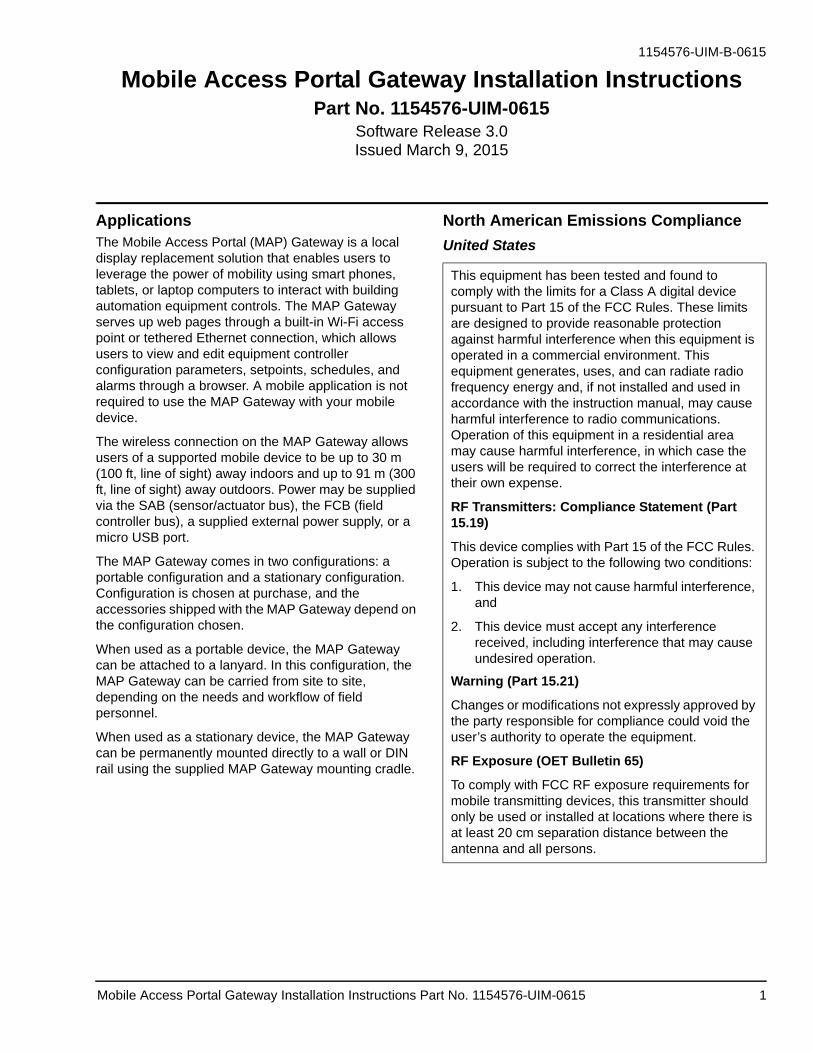
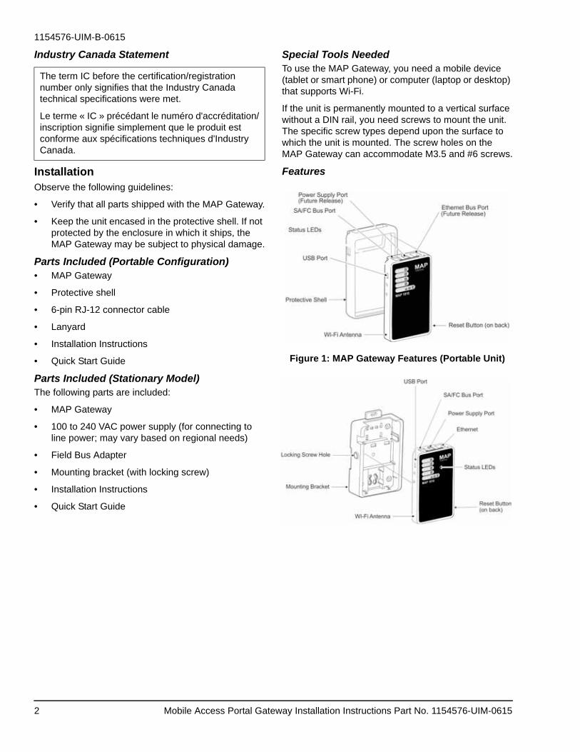
Features
Figure 1: MAP Gateway Features (Portable Unit)
The term IC before the certification/registration number only signifies that the Industry Canada technical specifications were met.
Le terme « IC » précédant le numéro d'accréditation/inscription signifie simplement que le produit est conforme aux spécifications techniques d'Industry Canada.
Mobile Access Portal Gateway Installation Instructions Part No. 1154576-UIM-06152
1154576-UIM-B-0615
Portable UseWhen used as a portable unit, the MAP Gateway should be housed in the supplied shell. During use, the unit can be temporarily hung on nearby equipment using the supplied lanyard.
Observe the following guidelines when using a portable MAP Gateway:
• Do not use the RJ-12 cable to support the weight of the MAP Gateway. Use the lanyard to support it.
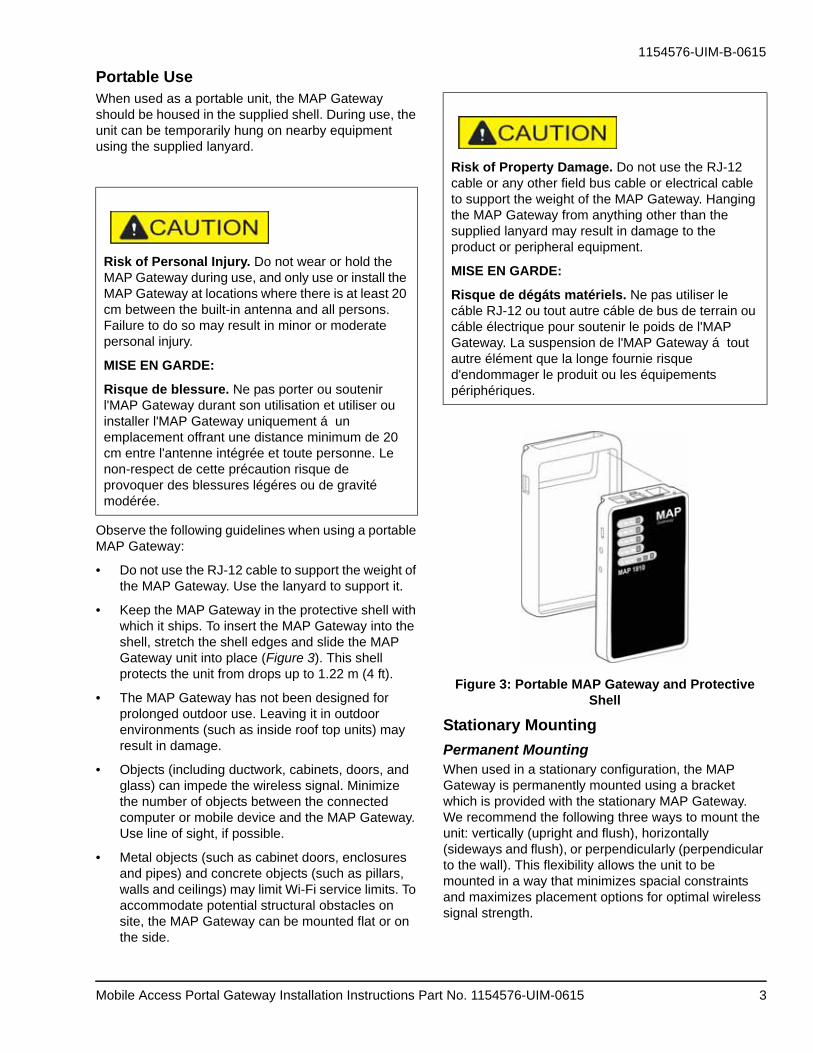
• Keep the MAP Gateway in the protective shell with which it ships. To insert the MAP Gateway into the shell, stretch the shell edges and slide the MAP Gateway unit into place (Figure 3). This shell protects the unit from drops up to 1.22 m (4 ft).
• The MAP Gateway has not been designed for prolonged outdoor use. Leaving it in outdoor environments (such as inside roof top units) may result in damage.
• Objects (including ductwork, cabinets, doors, and glass) can impede the wireless signal. Minimize the number of objects between the connected computer or mobile device and the MAP Gateway. Use line of sight, if possible.
• Metal objects (such as cabinet doors, enclosures and pipes) and concrete objects (such as pillars, walls and ceilings) may limit Wi-Fi service limits. To accommodate potential structural obstacles on site, the MAP Gateway can be mounted flat or on the side.
Figure 3: Portable MAP Gateway and Protective Shell
Stationary Mounting
Permanent MountingWhen used in a stationary configuration, the MAP Gateway is permanently mounted using a bracket which is provided with the stationary MAP Gateway. We recommend the following three ways to mount the unit: vertically (upright and flush), horizontally (sideways and flush), or perpendicularly (perpendicular to the wall). This flexibility allows the unit to be mounted in a way that minimizes spacial constraints and maximizes placement options for optimal wireless signal strength.
Risk of Personal Injury. Do not wear or hold the MAP Gateway during use, and only use or install the MAP Gateway at locations where there is at least 20 cm between the built-in antenna and all persons. Failure to do so may result in minor or moderate personal injury.
MISE EN GARDE:
Risque de blessure. Ne pas porter ou soutenir l'MAP Gateway durant son utilisation et utiliser ou installer l'MAP Gateway uniquement á un emplacement offrant une distance minimum de 20 cm entre l'antenne intégrée et toute personne. Le non-respect de cette précaution risque de provoquer des blessures légéres ou de gravité modérée.
Risk of Property Damage. Do not use the RJ-12 cable or any other field bus cable or electrical cable to support the weight of the MAP Gateway. Hanging the MAP Gateway from anything other than the supplied lanyard may result in damage to the product or peripheral equipment.
MISE EN GARDE:
Risque de dégáts matériels. Ne pas utiliser le cáble RJ-12 ou tout autre cáble de bus de terrain ou cáble électrique pour soutenir le poids de l'MAP Gateway. La suspension de l'MAP Gateway á tout autre élément que la longe fournie risque d'endommager le produit ou les équipements périphériques.
Mobile Access Portal Gateway Installation Instructions Part No. 1154576-UIM-0615 3
1154576-UIM-B-0615
The unit should be mounted in such a way that labels can be read if they are visible. (For example, do not mount the unit upside down, which puts the labels upside down.)
Location ConsiderationsObserve the following guidelines when mounting a MAP Gateway:
• Mount the MAP Gateway in areas free of corrosive vapors and observe the environmental limitations listed in the Technical Specifications section of this document.
• Objects (including ductwork, cabinets, doors, and glass) can impede the wireless signal. Minimize the number of objects between the connected computer or mobile device computer and the MAP Gateway. Use line of sight, if possible.
• Metal objects (such as cabinet doors, enclosures, and pipes) and concrete objects (such as pillars, walls, and ceilings) may limit Wi-Fi service. To accommodate potential structural obstacles on site, the MAP Gateway can be mounted flush against the wall or perpendicular to it.
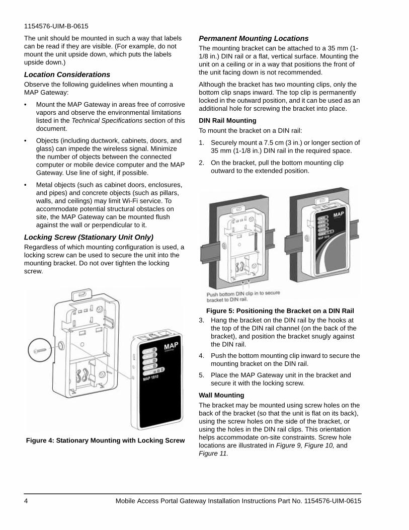
Locking Screw (Stationary Unit Only) Regardless of which mounting configuration is used, a locking screw can be used to secure the unit into the mounting bracket. Do not over tighten the locking screw.
Figure 4: Stationary Mounting with Locking Screw
Permanent Mounting LocationsThe mounting bracket can be attached to a 35 mm (1-1/8 in.) DIN rail or a flat, vertical surface. Mounting the unit on a ceiling or in a way that positions the front of the unit facing down is not recommended.
Although the bracket has two mounting clips, only the bottom clip snaps inward. The top clip is permanently locked in the outward position, and it can be used as an additional hole for screwing the bracket into place.
DIN Rail Mounting
To mount the bracket on a DIN rail:
1. Securely mount a 7.5 cm (3 in.) or longer section of 35 mm (1-1/8 in.) DIN rail in the required space.
2. On the bracket, pull the bottom mounting clip outward to the extended position.
Figure 5: Positioning the Bracket on a DIN Rail
3. Hang the bracket on the DIN rail by the hooks at the top of the DIN rail channel (on the back of the bracket), and position the bracket snugly against the DIN rail.
4. Push the bottom mounting clip inward to secure the mounting bracket on the DIN rail.
5. Place the MAP Gateway unit in the bracket and secure it with the locking screw.
Wall Mounting
The bracket may be mounted using screw holes on the back of the bracket (so that the unit is flat on its back), using the screw holes on the side of the bracket, or using the holes in the DIN rail clips. This orientation helps accommodate on-site constraints. Screw hole locations are illustrated in Figure 9, Figure 10, and Figure 11.
Mobile Access Portal Gateway Installation Instructions Part No. 1154576-UIM-06154
1154576-UIM-B-0615
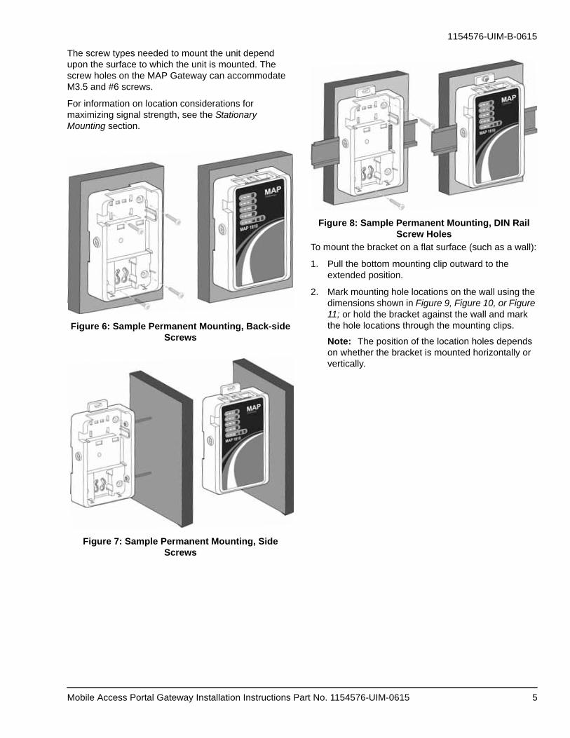
The screw types needed to mount the unit depend upon the surface to which the unit is mounted. The screw holes on the MAP Gateway can accommodate M3.5 and #6 screws.
For information on location considerations for maximizing signal strength, see the Stationary Mounting section.
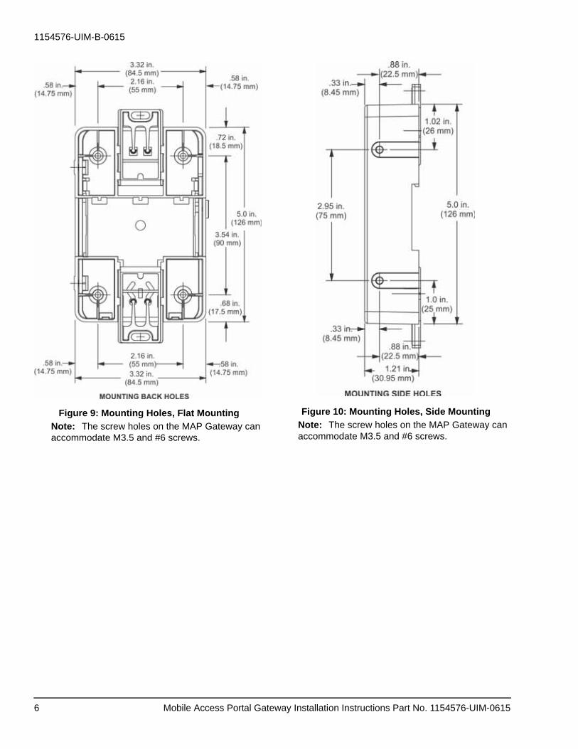
Figure 8: Sample Permanent Mounting, DIN Rail Screw Holes
To mount the bracket on a flat surface (such as a wall):
1. Pull the bottom mounting clip outward to the extended position.
2. Mark mounting hole locations on the wall using the dimensions shown in Figure 9, Figure 10, or Figure 11; or hold the bracket against the wall and mark the hole locations through the mounting clips.
Note: The position of the location holes depends on whether the bracket is mounted horizontally or vertically.
Mobile Access Portal Gateway Installation Instructions Part No. 1154576-UIM-0615 5
1154576-UIM-B-0615
Figure 9: Mounting Holes, Flat Mounting
Note: The screw holes on the MAP Gateway can accommodate M3.5 and #6 screws.
Figure 10: Mounting Holes, Side Mounting
Note: The screw holes on the MAP Gateway can accommodate M3.5 and #6 screws.
Mobile Access Portal Gateway Installation Instructions Part No. 1154576-UIM-06156
1154576-UIM-B-0615
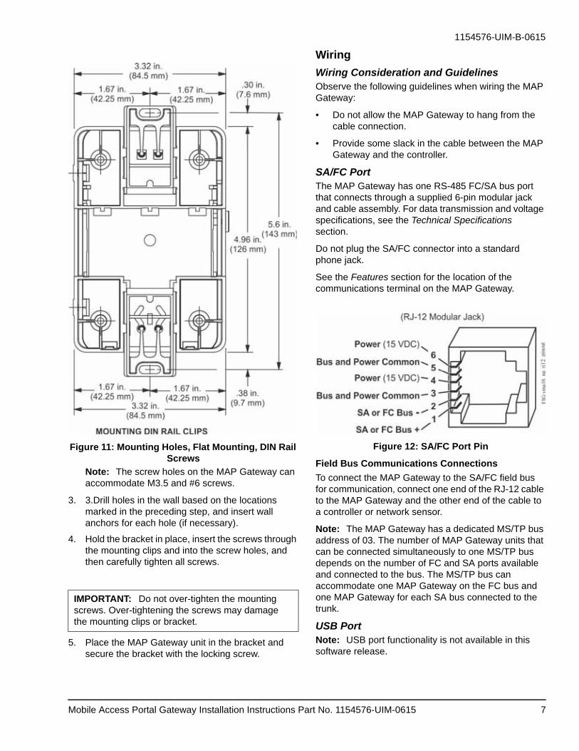
Figure 11: Mounting Holes, Flat Mounting, DIN Rail Screws
Note: The screw holes on the MAP Gateway can accommodate M3.5 and #6 screws.
3. 3.Drill holes in the wall based on the locations marked in the preceding step, and insert wall anchors for each hole (if necessary).
4. Hold the bracket in place, insert the screws through the mounting clips and into the screw holes, and then carefully tighten all screws.
5. Place the MAP Gateway unit in the bracket and secure the bracket with the locking screw.
Wiring
Wiring Consideration and GuidelinesObserve the following guidelines when wiring the MAP Gateway:
• Do not allow the MAP Gateway to hang from the cable connection.
• Provide some slack in the cable between the MAP Gateway and the controller.
SA/FC PortThe MAP Gateway has one RS-485 FC/SA bus port that connects through a supplied 6-pin modular jack and cable assembly. For data transmission and voltage specifications, see the Technical Specifications section.
Do not plug the SA/FC connector into a standard phone jack.
See the Features section for the location of the communications terminal on the MAP Gateway.
Figure 12: SA/FC Port Pin
Field Bus Communications Connections
To connect the MAP Gateway to the SA/FC field bus for communication, connect one end of the RJ-12 cable to the MAP Gateway and the other end of the cable to a controller or network sensor.
Note: The MAP Gateway has a dedicated MS/TP bus address of 03. The number of MAP Gateway units that can be connected simultaneously to one MS/TP bus depends on the number of FC and SA ports available and connected to the bus. The MS/TP bus can accommodate one MAP Gateway on the FC bus and one MAP Gateway for each SA bus connected to the trunk.
USB PortNote: USB port functionality is not available in this software release.
IMPORTANT: Do not over-tighten the mounting screws. Over-tightening the screws may damage the mounting clips or bracket.
Mobile Access Portal Gateway Installation Instructions Part No. 1154576-UIM-0615 7
1154576-UIM-B-0615
The USB port on the MAP Gateway is a 5-pin, Micro-B peripheral serial port which conforms to the USB 2.0 standard. The MAP Gateway USB port is for connecting to a computer for commissioning, downloading, and retrieving data. When the MAP Gateway is connected and powered from the USB port, FC/SA bus functions are not available.
Note: The USB connection on the MAP Gateway is not designed for constant use. The USB port should be used only when needed.
Ethernet PortThe Ethernet port on the MAP Gateway is an 8-pin RJ-45 jack. The maximum allowable cable length is 100 m (328 ft).
See the Features section for the location of the communications terminal on the MAP Gateway.
Note: If you use the Ethernet port to connect to the Operation MS/TP bus, power must be supplied by an external supply that is not the USB connection or the SA/FC bus connection. External power supply hardware varies by market. For information on the external power supply provided, see the Technical Specifications section.
External Power Supply ConnectionsNote: External power supply connections do not function in this software release.
If you use the Ethernet port to connect to the building network, an external power supply is needed. The power cord supplied varies by market. For information on the external power supply, see the Technical Specifications section.
To connect the MAP Gateway using the supplied external power source:
1. Connect the 15 VDC output connector of the power supply to the power supply port of the MAP Gateway.
2. 2.Connect the power supply to the supplied power cord.
3. Plug the power cord into a 100-240 VAC outlet.
Table 1: USB Port Pin Designations
Pin Number(Both Endsof Cable)
Signal Name
1 +5 VDC
2 Data
3 Data+
4 No Connection
5 Ground
Risk of Property Damage. Do not apply power to the system before checking all wiring connections. Short circuited or improperly connected wires may result in permanent damage to the equipment.
MISE EN GARDE:
Risque de dégáts matériels. Ne pas mettre le système sous tension avant d'avoir vérifié tous les raccords de câblage. Des fils formant un court-circuit ou connectés de façon incorrecte risquent d'endommager irrémédiablement l'équipement.
IMPORTANT: Power should only be applied and removed by connecting and disconnecting the power cord from the 100-240 VAC outlet. Applying or removing power by connecting or disconnecting the 15 VDC connector can damage the unit.
Risk of Electric Shock. Disconnect or isolate all power supplies before making electrical connections. More than one disconnection or isolation may be required to completely de-energize equipment. Contact with components carrying hazardous voltage can cause electric shock and may result in severe personal injury or death.
AVERTISSEMENT:
Risque de décharge électrique. Débrancher ou isoler toute alimentation avant de réaliser un branchement électrique. Plusieurs isolations et débranchements sont peut-être nécessaires pour -couper entièrement l'alimentation de l'équipement. Tout contact avec des composants conducteurs de tensions dangereuses risque d'entraîner une décharge électrique et de provoquer des blessures graves, voire mortelles.
Mobile Access Portal Gateway Installation Instructions Part No. 1154576-UIM-06158
1154576-UIM-B-0615
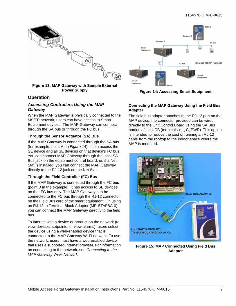
Figure 13: MAP Gateway with Sample External Power Supply
Operation
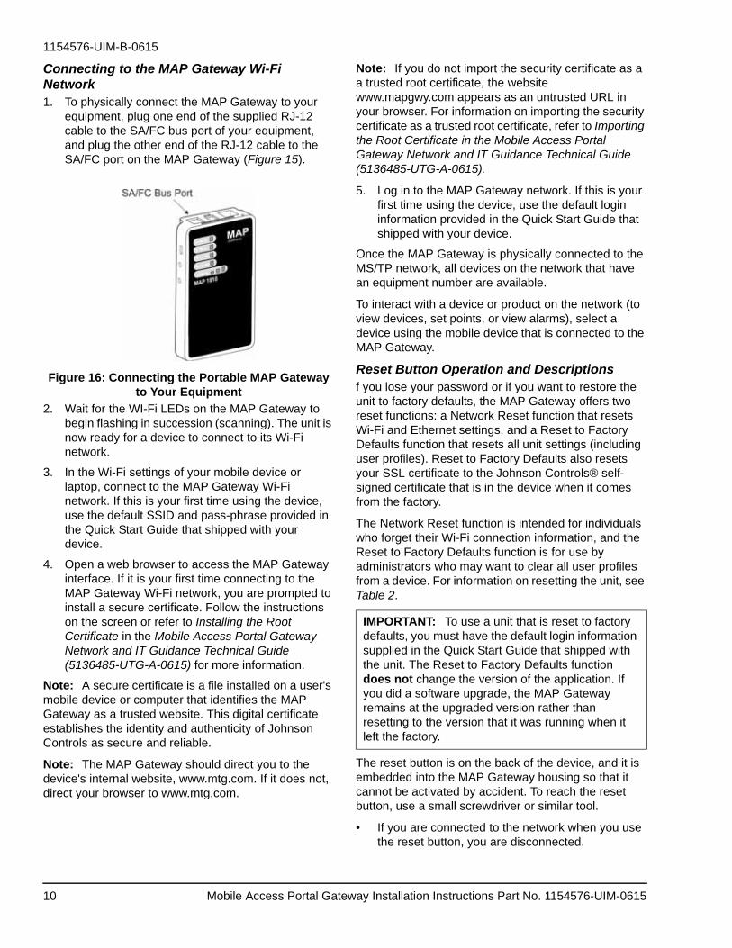
Accessing Controllers Using the MAP GatewayWhen the MAP Gateway is physically connected to the MS/TP network, users can have access to Smart Equipment devices. The MAP Gateway can connect through the SA bus or through the FC bus.
Through the Sensor Actuator (SA) Bus
If the MAP Gateway is connected through the SA bus (for example, point A on Figure 14), it can access the SE device and all SE devices on that device's FC bus. You can connect MAP Gateway through the local SA Bus jack on the equipment control board, or, if a Net Stat is installed, you can connect the MAP Gateway directly to the RJ-12 jack on the Net Stat.
Through the Field Controller (FC) Bus
If the MAP Gateway is connected through the FC bus (point B in the example), it has access to SE devices on that FC bus only. The MAP Gateway can be connected to the FC bus through the RJ-12 connector on the Field Bus card of the smart equipment. Or, using an RJ-12 to Terminal Block Adapter (MP-STAFBA-0), you can connect the MAP Gateway directly to the field bus.
To interact with a device or product on the network (to view devices, setpoints, or view alarms), users select the device using a web-enabled device that is connected to the MAP Gateway Wi-Fi network. To use the network, users must have a web-enabled device that uses a supported Internet browser. For information on connecting to the network, see Connecting to the MAP Gateway Wi-Fi Network.
Figure 14: Accessing Smart Equipment
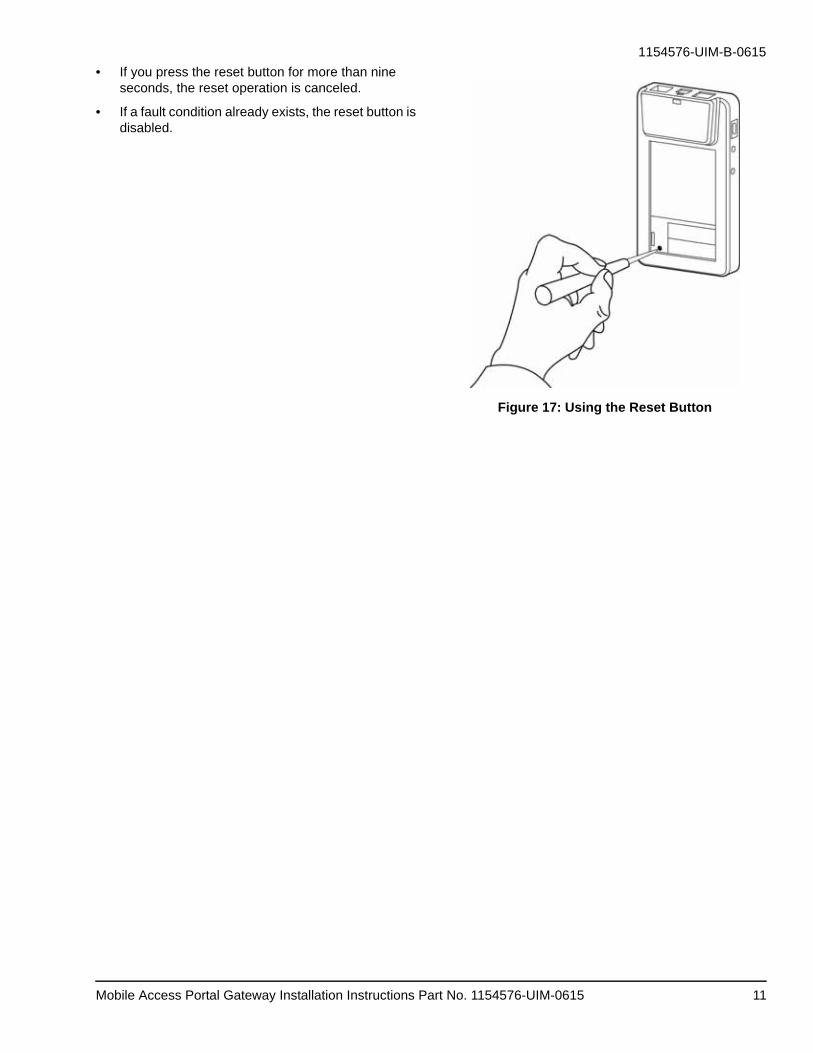
Connecting the MAP Gateway Using the Field Bus Adapter
The field bus adapter attaches to the RJ-12 port on the MAP device, the connector provided can be wired directly to the Unit Control Board using the SA Bus portion of the UCB (terminals +, -, C, PWR). This option is intended to reduce the cost of running an RJ-12 cable from the rooftop to the indoor space where the MAP is mounted.
Figure 15: MAP Connected Using Field Bus Adapter
FIELD BUS ADAPTER
L = LENGTH FROM RTUTO MAP MOUNTING LOCATION
L
Mobile Access Portal Gateway Installation Instructions Part No. 1154576-UIM-0615 9
1154576-UIM-B-0615
Connecting to the MAP Gateway Wi-Fi Network1. To physically connect the MAP Gateway to your
equipment, plug one end of the supplied RJ-12 cable to the SA/FC bus port of your equipment, and plug the other end of the RJ-12 cable to the SA/FC port on the MAP Gateway (Figure 15).
Figure 16: Connecting the Portable MAP Gateway to Your Equipment
2. Wait for the WI-Fi LEDs on the MAP Gateway to begin flashing in succession (scanning). The unit is now ready for a device to connect to its Wi-Fi network.
3. In the Wi-Fi settings of your mobile device or laptop, connect to the MAP Gateway Wi-Fi network. If this is your first time using the device, use the default SSID and pass-phrase provided in the Quick Start Guide that shipped with your device.
4. Open a web browser to access the MAP Gateway interface. If it is your first time connecting to the MAP Gateway Wi-Fi network, you are prompted to install a secure certificate. Follow the instructions on the screen or refer to Installing the Root Certificate in the Mobile Access Portal Gateway Network and IT Guidance Technical Guide (5136485-UTG-A-0615) for more information.
Note: A secure certificate is a file installed on a user's mobile device or computer that identifies the MAP Gateway as a trusted website. This digital certificate establishes the identity and authenticity of Johnson Controls as secure and reliable.
Note: The MAP Gateway should direct you to the device's internal website, www.mtg.com. If it does not, direct your browser to www.mtg.com.
Note: If you do not import the security certificate as a a trusted root certificate, the website www.mapgwy.com appears as an untrusted URL in your browser. For information on importing the security certificate as a trusted root certificate, refer to Importing the Root Certificate in the Mobile Access Portal Gateway Network and IT Guidance Technical Guide (5136485-UTG-A-0615).
5. Log in to the MAP Gateway network. If this is your first time using the device, use the default login information provided in the Quick Start Guide that shipped with your device.
Once the MAP Gateway is physically connected to the MS/TP network, all devices on the network that have an equipment number are available.
To interact with a device or product on the network (to view devices, set points, or view alarms), select a device using the mobile device that is connected to the MAP Gateway.
Reset Button Operation and Descriptionsf you lose your password or if you want to restore the unit to factory defaults, the MAP Gateway offers two reset functions: a Network Reset function that resets Wi-Fi and Ethernet settings, and a Reset to Factory Defaults function that resets all unit settings (including user profiles). Reset to Factory Defaults also resets your SSL certificate to the Johnson Controls® self-signed certificate that is in the device when it comes from the factory.
The Network Reset function is intended for individuals who forget their Wi-Fi connection information, and the Reset to Factory Defaults function is for use by administrators who may want to clear all user profiles from a device. For information on resetting the unit, see Table 2.
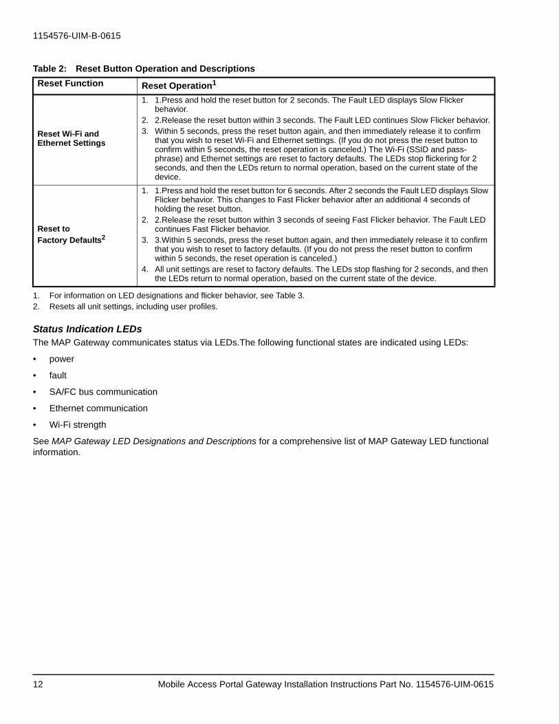
The reset button is on the back of the device, and it is embedded into the MAP Gateway housing so that it cannot be activated by accident. To reach the reset button, use a small screwdriver or similar tool.
• If you are connected to the network when you use the reset button, you are disconnected.
IMPORTANT: To use a unit that is reset to factory defaults, you must have the default login information supplied in the Quick Start Guide that shipped with the unit. The Reset to Factory Defaults function does not change the version of the application. If you did a software upgrade, the MAP Gateway remains at the upgraded version rather than resetting to the version that it was running when it left the factory.
Mobile Access Portal Gateway Installation Instructions Part No. 1154576-UIM-061510
1154576-UIM-B-0615
• If you press the reset button for more than nine seconds, the reset operation is canceled.
• If a fault condition already exists, the reset button is disabled.
Figure 17: Using the Reset Button
Mobile Access Portal Gateway Installation Instructions Part No. 1154576-UIM-0615 11
1154576-UIM-B-0615
Status Indication LEDsThe MAP Gateway communicates status via LEDs.The following functional states are indicated using LEDs:
• power
• fault
• SA/FC bus communication
• Ethernet communication
• Wi-Fi strength
See MAP Gateway LED Designations and Descriptions for a comprehensive list of MAP Gateway LED functional information.
Table 2: Reset Button Operation and Descriptions
Reset Function Reset Operation1
Reset Wi-Fi and Ethernet Settings
1. 1.Press and hold the reset button for 2 seconds. The Fault LED displays Slow Flicker behavior.
2. 2.Release the reset button within 3 seconds. The Fault LED continues Slow Flicker behavior.3. Within 5 seconds, press the reset button again, and then immediately release it to confirm
that you wish to reset Wi-Fi and Ethernet settings. (If you do not press the reset button to confirm within 5 seconds, the reset operation is canceled.) The Wi-Fi (SSID and pass-phrase) and Ethernet settings are reset to factory defaults. The LEDs stop flickering for 2 seconds, and then the LEDs return to normal operation, based on the current state of the device.
Reset toFactory Defaults2
1. 1.Press and hold the reset button for 6 seconds. After 2 seconds the Fault LED displays Slow Flicker behavior. This changes to Fast Flicker behavior after an additional 4 seconds of holding the reset button.
2. 2.Release the reset button within 3 seconds of seeing Fast Flicker behavior. The Fault LED continues Fast Flicker behavior.
3. 3.Within 5 seconds, press the reset button again, and then immediately release it to confirm that you wish to reset to factory defaults. (If you do not press the reset button to confirm within 5 seconds, the reset operation is canceled.)
4. All unit settings are reset to factory defaults. The LEDs stop flashing for 2 seconds, and then the LEDs return to normal operation, based on the current state of the device.
1. For information on LED designations and flicker behavior, see Table 3.2. Resets all unit settings, including user profiles.
Mobile Access Portal Gateway Installation Instructions Part No. 1154576-UIM-061512
1154576-UIM-B-0615
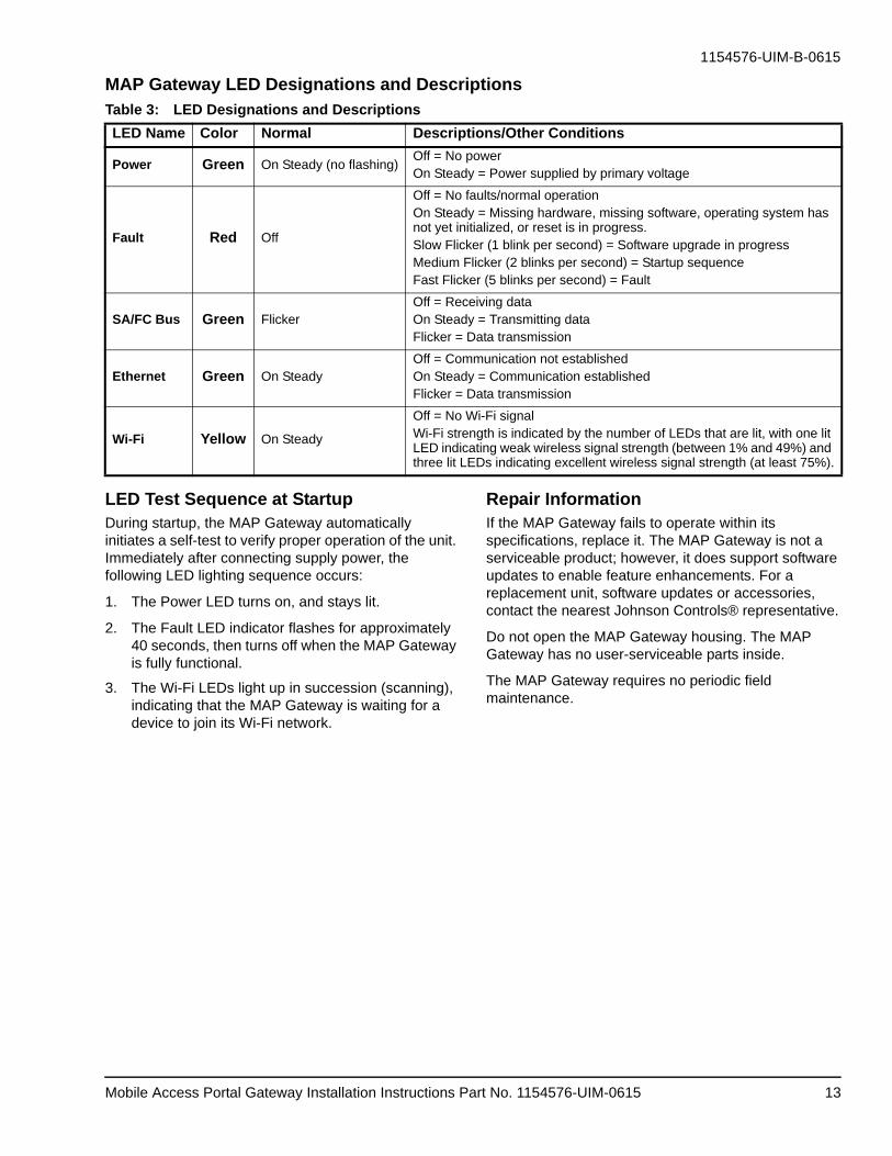
MAP Gateway LED Designations and Descriptions
LED Test Sequence at StartupDuring startup, the MAP Gateway automatically initiates a self-test to verify proper operation of the unit. Immediately after connecting supply power, the following LED lighting sequence occurs:
1. The Power LED turns on, and stays lit.
2. The Fault LED indicator flashes for approximately 40 seconds, then turns off when the MAP Gateway is fully functional.
3. The Wi-Fi LEDs light up in succession (scanning), indicating that the MAP Gateway is waiting for a device to join its Wi-Fi network.
Repair InformationIf the MAP Gateway fails to operate within its specifications, replace it. The MAP Gateway is not a serviceable product; however, it does support software updates to enable feature enhancements. For a replacement unit, software updates or accessories, contact the nearest Johnson Controls® representative.
Do not open the MAP Gateway housing. The MAP Gateway has no user-serviceable parts inside.
The MAP Gateway requires no periodic field maintenance.
Table 3: LED Designations and Descriptions
LED Name Color Normal Descriptions/Other Conditions
Power Green On Steady (no flashing)Off = No powerOn Steady = Power supplied by primary voltage
Fault Red Off
Off = No faults/normal operationOn Steady = Missing hardware, missing software, operating system has not yet initialized, or reset is in progress.Slow Flicker (1 blink per second) = Software upgrade in progressMedium Flicker (2 blinks per second) = Startup sequenceFast Flicker (5 blinks per second) = Fault
SA/FC Bus Green FlickerOff = Receiving dataOn Steady = Transmitting dataFlicker = Data transmission
Ethernet Green On SteadyOff = Communication not establishedOn Steady = Communication establishedFlicker = Data transmission
Wi-Fi Yellow On Steady
Off = No Wi-Fi signalWi-Fi strength is indicated by the number of LEDs that are lit, with one lit LED indicating weak wireless signal strength (between 1% and 49%) and three lit LEDs indicating excellent wireless signal strength (at least 75%).
Mobile Access Portal Gateway Installation Instructions Part No. 1154576-UIM-0615 13
1154576-UIM-B-0615
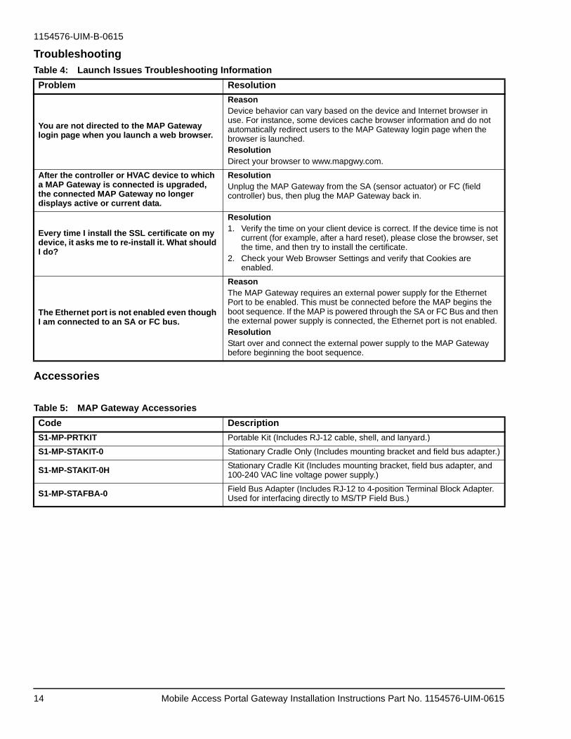
Troubleshooting
Accessories
Table 4: Launch Issues Troubleshooting Information
Problem Resolution
You are not directed to the MAP Gateway login page when you launch a web browser.
ReasonDevice behavior can vary based on the device and Internet browser in use. For instance, some devices cache browser information and do not automatically redirect users to the MAP Gateway login page when the browser is launched.ResolutionDirect your browser to www.mapgwy.com.
After the controller or HVAC device to which a MAP Gateway is connected is upgraded, the connected MAP Gateway no longer displays active or current data.
ResolutionUnplug the MAP Gateway from the SA (sensor actuator) or FC (field controller) bus, then plug the MAP Gateway back in.
Every time I install the SSL certificate on my device, it asks me to re-install it. What should I do?
Resolution1. Verify the time on your client device is correct. If the device time is not
current (for example, after a hard reset), please close the browser, set the time, and then try to install the certificate.
2. Check your Web Browser Settings and verify that Cookies are enabled.
The Ethernet port is not enabled even though I am connected to an SA or FC bus.
ReasonThe MAP Gateway requires an external power supply for the Ethernet Port to be enabled. This must be connected before the MAP begins the boot sequence. If the MAP is powered through the SA or FC Bus and then the external power supply is connected, the Ethernet port is not enabled.ResolutionStart over and connect the external power supply to the MAP Gateway before beginning the boot sequence.
Table 5: MAP Gateway Accessories
Code Description
S1-MP-PRTKIT Portable Kit (Includes RJ-12 cable, shell, and lanyard.)
S1-MP-STAKIT-0 Stationary Cradle Only (Includes mounting bracket and field bus adapter.)
S1-MP-STAKIT-0H Stationary Cradle Kit (Includes mounting bracket, field bus adapter, and 100-240 VAC line voltage power supply.)
S1-MP-STAFBA-0Field Bus Adapter (Includes RJ-12 to 4-position Terminal Block Adapter. Used for interfacing directly to MS/TP Field Bus.)
Mobile Access Portal Gateway Installation Instructions Part No. 1154576-UIM-061514
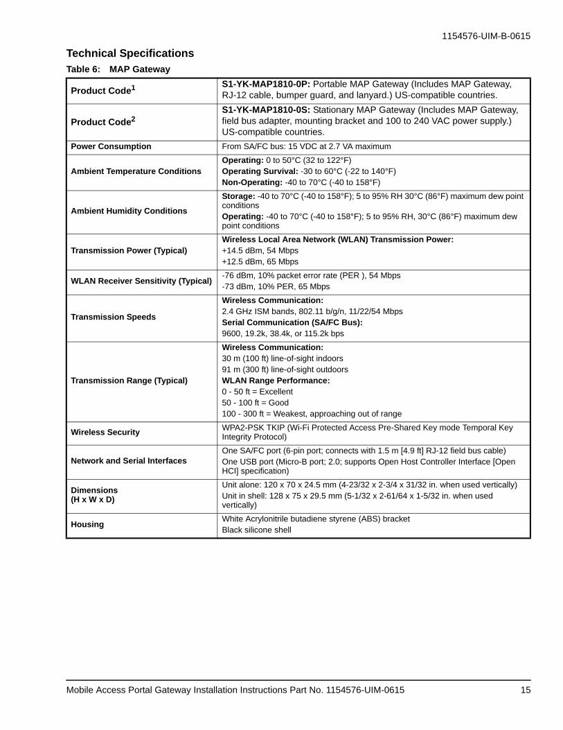
Product Code2S1-YK-MAP1810-0S: Stationary MAP Gateway (Includes MAP Gateway, field bus adapter, mounting bracket and 100 to 240 VAC power supply.) US-compatible countries.
Power Consumption From SA/FC bus: 15 VDC at 2.7 VA maximum
Ambient Temperature ConditionsOperating: 0 to 50°C (32 to 122°F)Operating Survival: -30 to 60°C (-22 to 140°F)Non-Operating: -40 to 70°C (-40 to 158°F)
Ambient Humidity Conditions
Storage: -40 to 70°C (-40 to 158°F); 5 to 95% RH 30°C (86°F) maximum dew point conditionsOperating: -40 to 70°C (-40 to 158°F); 5 to 95% RH, 30°C (86°F) maximum dew point conditions
Transmission Power (Typical)Wireless Local Area Network (WLAN) Transmission Power:+14.5 dBm, 54 Mbps+12.5 dBm, 65 Mbps
Wireless Communication:2.4 GHz ISM bands, 802.11 b/g/n, 11/22/54 MbpsSerial Communication (SA/FC Bus):9600, 19.2k, 38.4k, or 115.2k bps
Transmission Range (Typical)
Wireless Communication:30 m (100 ft) line-of-sight indoors91 m (300 ft) line-of-sight outdoorsWLAN Range Performance:0 - 50 ft = Excellent50 - 100 ft = Good100 - 300 ft = Weakest, approaching out of range
Network and Serial InterfacesOne SA/FC port (6-pin port; connects with 1.5 m [4.9 ft] RJ-12 field bus cable)One USB port (Micro-B port; 2.0; supports Open Host Controller Interface [Open HCI] specification)
Dimensions(H x W x D)
Unit alone: 120 x 70 x 24.5 mm (4-23/32 x 2-3/4 x 31/32 in. when used vertically)Unit in shell: 128 x 75 x 29.5 mm (5-1/32 x 2-61/64 x 1-5/32 in. when used vertically)
Mobile Access Portal Gateway Installation Instructions Part No. 1154576-UIM-0615 15
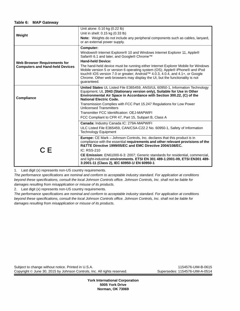
Weight
Unit alone: 0.10 kg (0.22 lb)Unit in shell: 0.15 kg (0.33 lb)Note: Weights do not include any peripheral components such as cables, lanyard, or an external power supply.
Web Browser Requirements for Computers and Hand-held Devices
Computer:Windows® Internet Explorer® 10 and Windows Internet Explorer 11, Apple® Safari® 6.1 and later, and Google® Chrome™Hand-held Device:The hand-held device must be running either Internet Explorer Mobile for Windows Mobile version 5 or version 6 operating system (OS); Apple® iPhone® and iPod touch® iOS version 7.0 or greater; Android™ 4.0.3, 4.0.4, and 4.1+, or Google Chrome. Other web browsers may display the UI, but the functionality is not guaranteed.
Compliance
C E
United States UL Listed File E365459, ANSI/UL 60950-1, Information Technology Equipment; UL 2043 (Stationary version only), Suitable for Use in Other Environmental Air Space in Accordance with Section 300.22, (C) of the National Electric Code.Transmission Complies with FCC Part 15.247 Regulations for Low Power Unlicensed TransmittersTransmitter FCC Identification: OEJ-MAPWIFIFCC Compliant to CFR 47, Part 15, Subpart B, Class A
Canada: Industry Canada IC: 279A-MAPWIFIULC Listed File E365459, CAN/CSA-C22.2 No. 60950-1, Safety of Information Technology Equipment
Europe: CE Mark – Johnson Controls, Inc. declares that this product is in compliance with the essential requirements and other relevant provisions of the R&TTE Directive 1999/05/EC and EMC Directive 2004/108/EC.IC: RSS-210CE Emission: EN61000-6-3: 2007; Generic standards for residential, commercial, and light-industrial environments. ETSI EN 301 489-1:2001-09, ETSI EN301 489-3:2001-11 (Class 2), IEC 60950-1/ EN 60950-1
1. Last digit (x) represents non-US country requirements.The performance specifications are nominal and conform to acceptable industry standard. For application at conditionsbeyond these specifications, consult the local Johnson Controls office. Johnson Controls, Inc. shall not be liable fordamages resulting from misapplication or misuse of its products.2. Last digit (x) represents non-US country requirements.The performance specifications are nominal and conform to acceptable industry standard. For application at conditionsbeyond these specifications, consult the local Johnson Controls office. Johnson Controls, Inc. shall not be liable fordamages resulting from misapplication or misuse of its products.