BASE PRODUCT TYPE NOMINAL CAPACITY UNIT DESIGNATION REFRIGERANT VOLTAGE / STARTER DESIGN / DEVELOPMENT LEVEL
Y : York # # # # kW S : Standard Unit E : R-410A 4 0 X : 380 / 3 / 60 B : Design Series
L : Scroll 0115 0145 0170 X : Direct on Line A : Development Level
P : Heat Pump
A : All Regions
IntroductionCONTENTSIntroduction .................................................................................................................................................................................................................. 2Product Description .................................................................................................................................................................................................... 3Microcomputer Control Center .................................................................................................................................................................................. 4Accessories and Options ........................................................................................................................................................................................... 5Refrigerant Flow Block Diagrams .............................................................................................................................................................................. 6Component Location ................................................................................................................................................................................................... 7Application Data .......................................................................................................................................................................................................... 8Connection Diagram ................................................................................................................................................................................................. 14Water Pressure Drop ................................................................................................................................................................................................. 15Ratings ....................................................................................................................................................................................................................... 16Technical Data ........................................................................................................................................................................................................... 19Dimensions ................................................................................................................................................................................................................ 21
FORM 150.68-EG1 (0212)
3JOHNSON CONTROLS
Product DescriptionYLPA air-to-liquid reversible heat pumps are completely factory assembled with all interconnecting refrigerant piping and wiring ready for fi eld installation. The unit is pressure tested, evacuated, and fully factory charged with refrigerant R410A and oil in each of the independent refrigerant circuits. After assembly, an operational test is performed with water fl owing through the heat exchanger to ensure that each refrigerant circuit operates correctly.
The unit structure is manufactured from heavy-gauge, galvanised steel coated with baked-on powder paint (Champagne (RAL 7006, Munsell No. 9.8YR4.36/1.2)).
YLPA heat pumps are designed in accordance with NFPA 70 (National Electric Code), ASHRAE/ANSI 15 Safety code for mechanical refrigeration, ASME and rated in accordance with ARI Standard 550/590.
COMPRESSORS
The unit has suction-cooled, hermetic scroll compressors. High effi ciency is achieved through a controlled orbit and the use of advanced scroll geometry. The compressors incorporate a compliant scroll design in both the axial and radial directions. All rotating parts are statically and dynamically balanced. The compressor motors have integral protection against overloads that will automatically reset. Starting is direct on line, and soft start is available as an option.
The compressors are switched On and Off by the unit microprocessor to provide capacity control. Each compressor is fi tted with a crankcase strap heater. All compressors are mounted on isolator pads to reduce transmission of vibration to the rest of the unit.
The motor terminal boxes have IP54 weather protection.
REFRIGERANT CIRCUITS
Two independent refrigerant circuits are provided on each unit. Each circuit uses copper refrigerant pipe formed on computer controlled bending machines to reduce the number of brazed joints resulting in a high integrity and reliable system.
Each circuit shall incorporate all components necessary for the designed operation including: a suction accumulator; a liquid receiver; a four way reversing valve which changes the direction of the refrigerant fl ow and the function of the heat exchanger when switching between cooling and heating modes; service valves; isolation (ball/angle) valves; pressure relief valves; a high absorption removable core fi lter-drier; a sight glass with moisture indicator; a cooling mode thermal expansion valve and a heat pump mode thermal expansion valve. Suction lines shall be covered with closed-cell insulation.
REFRIGERANT TO WATER HEAT EXCHANGER
The 2-pass dual circuit shell and tube type direct expansion (DX) heat exchanger has refrigerant in the tubes and liquid fl owing through the baffl ed shell. The waterside (shell) design working pressure is 10 barg. The refrigerant side (tubes) design working pressure is 45 barg. The refrigerant side is protected by pressure relief valve(s).
The heat exchanger is equipped with a heater for frost protection to -4°F (below this the ball valve in the discharge line must be closed) and insulated with fl exible closed-cell foam. Water connection to the heat exchanger is via victaulic grooved connections. Victaulic groove to fl ange converters are available as an option
AMBIENT COILS
The ambient coils are seamless copper tubes, arranged in staggered rows, mechanically expanded into coated aluminium fi ns. Integral sub-cooling is included.
The condenser fans have composite metal/plastic ̀ sickle` blades integrated into the rotor of an external rotor motor. They are designed for maximum effi ciency and statically and dynamically balanced for vibration free operation. They are directly driven by independent motors, and positioned for vertical air discharge. The fan guards are constructed from heavy-gauge, corrosion resistant, coated steel.
The IP54 fan motors are the totally enclosed air-over type with permanently lubricated double-sealed ball bearings.
POWER AND CONTROL PANELS
All power and controls are contained in an IP 55 cabinet with hinged and gasket sealed outer doors. The power panel includes:
• Factory mounted non-fused disconnect switch with external red/yellow, lockable handle to enable connection of the unit power supply. The disconnect switch can be used to isolate the power for servicing and as a emergency stop.
• Factory mounted compressor contactors and compressor fuses provide short circuit protection. Overload protection for each compressor is provided by inherent motor winding temperature sensing and a trip module.
• Factory mounted fan contactors and fuses provide short circuit protection. Overload protection for each fan is provided by a inherent motor winding temperature device.
• Factory mounted control transformer to convert the unit supply voltage to 115 V - 1 Ø - 60 Hz for the control system.
• Control supply fuses and connections for a remote emergency stop device.
JOHNSON CONTROLS4
FORM 150.68-EG1 (0212)
Microcomputer Control CenterThe control panel includes:
• A Liquid Crystal Display (two display lines of twenty characters per line) with Light Emitting Diode backlighting for easy viewing
• A Colour coded 12-button keypad• Customer terminal blocks for control inputs and liquid
fl ow switch.
The microprocessor control includes:
• Automatic control of compressor start/stop, anticoincidence and anti-recycle timers, pump and unit alarm contacts. Automatic reset to normal unit operation after power failure.
• Remote water temperature setpoint reset via analog input or a pulse width modulated (PWM) input signal or up to two steps of demand (load) limiting.
• Software is loaded into the microprocessor controller via a SD card, with programmed setpoints retained in a lithium battery backed real time clock (RTC) memory.
• Forty character liquid crystal display, with description available in fi ve languages (English, French, German, Spanish or Italian)
Programmable setpoints:
• Chilled liquid temperature setpoint and range• Hot liquid temperature setpoint and range• Remote reset temperature range• Set daily schedule/holiday for start/stop• Manual override for servicing• Low ambient cutout• High ambient cutout (heating only - fi xed)• Low liquid temperature cutout• Low suction pressure cutout• High discharge pressure cutout• Anti-recycle timer (compressor start cycle time)• Anti-coincident timer (delay compressor starts)
Displayed Data:
• Leaving liquid temperature • Air coil defrost temperatures• Low leaving liquid temperature cutout setting• Low ambient temperature cutout setting• Ambient air temperature• Metric or Imperial data• Discharge and suction pressure cutout settings• System discharge and suction pressures• Anti-recycle timer status for each system• Anti-coincident system start timer condition• Compressor run status• No load condition• Day, date and time• Daily start/stop times• Holiday status• Automatic or manual system lead/lag control• Lead system defi nition• Compressor starts & operating hours (each
compressor)• Status of evaporator heater and fan operation• Run permissive status• Number of compressors running• Mode solenoid valve status• Load & unload timer status• Liquid pump status
System Safeties:
• Cause individual compressors to perform auto shut down and require manual reset in the event of 3 trips in a 90-minute time period
• High discharge pressure• Low suction pressure• High-pressure switches• Motor protector
Unit Safeties:
They are automatic reset and cause compressor to shut down
• Low leaving chilled liquid temperature• Under voltage• Loss of liquid fl ow (through fl ow switch)
Accessories and OptionsFLOW SWITCH - The fl ow switch or its equivalent must be furnished with each unit. 150 psig (10.5 bar) DWP - For standard units. Johnson Controls model F61MG-1C Vapor-proof SPDT, NEMA 3R switch (150 PSIG [10.5 bar] DWP), -20°F to 250°F (-29°C to 121°C), with 1” NPT connection for upright mounting in horizontal pipe. (Field-mounted)
CHICAGO CODE RELIEF VALVES - Unit will be provided with relief valves to meet Chicago code requirements. (Factory-Mounted)
NEOPRENE PADS ISOLATORS - Recommended for normal installations (Field mounted)
1” SPRING ISOLATORS - Level adjustable, spring and cage type isolators for mounting under the unit base rails (Field mounted).
2” SPRING ISOLATORS - Restrained Spring-Flex Mountings incorporating a rugged welded steel housing with vertical and horizontal limit stops. (Field mounted).
FLANGE KIT - Provides contractor with the couplings best suited to tie into the chilled water piping. All fl anges are PN10.
SINGLE-POINT SUPPLY TERMINAL BLOCK - Includes enclosure, terminal-block and interconnecting wiring to the compressors. Separate external protection must be supplied, by others, in the incoming compressor-power wiring. (Do not include this option if either the Single-Point Non-Fused Disconnect Switch or Single-Point Circuit Breaker options have been included.)
SINGLE-POINT CIRCUIT BREAKER - A unit mounted circuit breaker with external, lockable handle (in compliance with N.E.C. Article 440-14), can be supplied to isolate the power voltage for servicing. (This option includes the Single-Point Power connection.)
JOHNSON CONTROLS6
FORM 150.68-EG1 (0212)
Refrigerant Flow Block DiagramsCOOLING MODE
Low pressure liquid refrigerant enters the heat exchanger and is evaporated and superheated by the heat energy absorbed from the chilled liquid. Low pressure vapor enters the compressor, via the four-way reversing valve and accumulator, where pressure and superheat are increased. The high pressure vapor is fed to the ambient coils and fans - via the four way reversing valve which changes the direction of the refrigerant fl ow and the function of the heat exchanger to cooling mode - where heat is removed. The fully condensed and subcooled liquid passes through the expansion valve (cooling) where pressure is reduced and further cooling takes place before returning to the heat exchanger.
HEATING MODE
Liquid refrigerant enters the ambient coil and is fully evaporated and superheated by the energy absorbed from the ambient air. Low-pressure superheated refrigerant vapor passes through the four-way reversing valve - which changes the direction of the refrigerant fl ow and the function of the heat exchanger to heating mode - and the accumulator and enters the compressor, where pressure and superheat are increased. High-pressure superheated refrigerant vapor enters the refrigerant to water plate heat exchanger where heat is rejected to the water. The high-pressure liquid refrigerant, leaving the heat exchanger passes through the liquid receiver and enters thermostatic expansion valve (heating) where the refrigerant and subsequently cooled before returning to the ambient coil.
Defrost Operation
When ice builds up on the ambient coils defrost is initiated by operating the machine in a cooling mode. Each of the two refrigerant circuits will be defrosted one at a time. When defrost is operative the circuit operating in heating mode is in balance with the circuit operating in defrost (cooling). Therefore, heat energy is not removed from the hot water system.
Ambient Coils (Condenser)
Refrigerant flow
Compressors Heat Exchanger (Evaporator)
4-way valve
Accumulator
Receiver
TXV (heating)
TXV (cooling)
Ambient Coils (Evaporator)
Refrigerant flow
Compressors Heat Exchanger (Condenser)
4-way valve
Accumulator
Receiver iverR
TXV (heating)
TXV (cooling)
FORM 150.68-EG1 (0212)
7JOHNSON CONTROLS
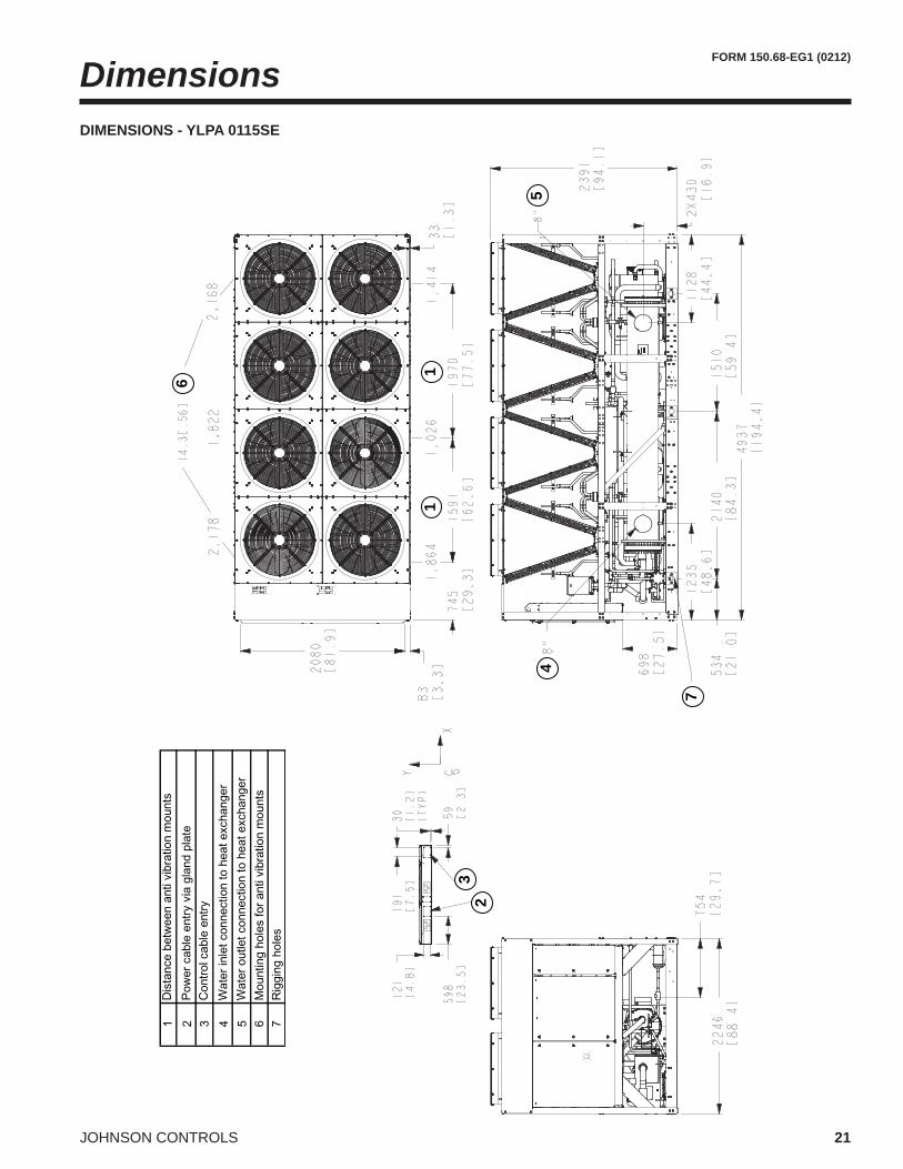
Component Location
1
2
3
8
54
67
1 Power Panel 5 Heat Exchanger2 Non-Fused Disconnect Switch 6 Suction Accumulator3 Control Panel 7 Ambient Coils4 Compressors 8 Fans
WEIGHTS AND WEIGHT DISTRIBUTION
The weights and weight distribution are given below:
To achieve optimum performance and trouble-free service, it is essential that the proposed installation site meet with the location and space requirements for the model being installed.
The clearances recommended are nominal for the safe and effi cient operation and maintenance of the unit and power and control panels. Local Health and safety regulations, or practical considerations for service replacement of large components, may require larger clearances than those given in this manual.
OUTDOOR INSTALLATIONS
The units can be installed at ground level on a suitable at level foundation easily capable of supporting the weight of the unit, or on a suitable rooftop location. In both cases an adequate supply of air is required. Avoid locations where the sound output and air discharge from the unit may be objectionable.
The location should be selected for minimum sun exposure and away from boiler fl ues and other sources of airborne chemicals that could attack the condenser coils and steel parts of the unit.
If located in an area accessible to unauthorized persons, steps must be taken to prevent access to the unit by means of a protective fence. This will help to prevent the possibility of vandalism, accidental damage, or possible harm caused by unauthorized removal of protective guards or opening panels to expose rotating or electrically live components.
For ground level locations, the unit must be installed on a suitable fl at and level concrete base that extends to fully support the two side channels of the unit base frame. A one-piece concrete slab, with footings extending below the frost line is recommended. To avoid noise and vibration transmission, the unit should not be secured to the building foundation.
On rooftop locations, choose a place with adequate structural strength to safely support the entire operating weight of the unit and service personnel. The unit can be mounted on a concrete slab, similar to ground fl oor locations, or on steel channels of suitable strength. The channels should be spaced with the same centres as the unit side and front base rails. This will allow vibration isolators to be fi tted if required. Isolators are recommended for rooftop locations.
LOCATION CLEARANCES
Adequate clearances around the unit(s) are required for the unrestricted air-fl ow for the ambient coils and to prevent re-circulation of discharge air back onto the coils. If clearances given are not maintained, air-fl ow restriction or re-circulation will cause a loss of unit performance, an increase in power consumption, and may cause the unit to malfunction. Consideration should also be given to the possibility of down drafts, caused by adjacent buildings, which may cause re-circulation or uneven unit air-fl ow.
For locations where signifi cant cross winds are expected, such as exposed roof tops, an enclosure of solid or louvre type is recommended to prevent wind turbulence interfering with the unit air-fl ow.
When units are installed in an enclosure, the enclosure height should not exceed the height of the unit on more than one side. Where accumulation of snow is likely, additional height must be provided under the unit to ensure normal air-fl ow to the unit.
Refer to the table below and the diagrams on the following page for location clearances.
An optional set of vibration isolators can be supplied loose with each unit.
PIPEWORK CONNECTION
The following piping recommendations are intended to ensure satisfactory operation of the unit. Failure to follow these recommendations could cause damage to the unit, or loss of performance, and may invalidate the warranty.
A fl ow switch must be installed in the customer pipework at the outlet of the heat exchanger as shown in the arrangement diagrams, and wired back to the control panel using screened cable. This is to prevent damage to the heat exchanger caused by inadequate liquid fl ow. To prevent turbulent fl ow, there must be straight pipework either side of the fl ow switch equal in length to at least 5 times the diameter of the pipe.
The fl ow switches used must have gold plated contacts for low voltage/current operation
Alternatively, a differential pressure switch fi tted across an orifi ce plate may be used, preferably of the high/low limit type.
The liquid pumps installed in the pipework systems should discharge directly into the unit heat exchanger sections of the system. The pumps require an auto-starter (by others) to be wired to the control panel.
Pipework and fi ttings must be separately supported to prevent any loading on the heat exchanger(s). Flexible connections are recommended which will also minimize transmission of vibrations to the building. Flexible connections must be used if the unit is mounted on anti-vibration mounts as some movement of the unit can be expected in normal operation.
Pipework and fittings immediately next to the heat exchanger(s) should be readily demountable to enable cleaning prior to operation, and to facilitate visual inspection of the exchanger nozzles.
Each heat exchanger must be protected by a strainer, preferably of 20 mesh, fi tted as close as possible to the liquid inlet connection, and provided with a means of local isolation.
The heat exchanger(s) must not be exposed to fl ushing velocities or debris released during flushing. It is recommended that a suitably sized by-pass and valve arrangement be installed to allow fl ushing of the pipework system. The by-pass can be used during maintenance to isolate the heat exchanger(s) without disrupting fl ow to other units.
Thermometer and pressure gauge connections should be provided on the inlet and outlet connections of each heat exchanger.
Drain and air vent connections should be provided at all low and high points in the pipework to permit drainage of the system, and to vent any air in the pipes.
Liquid systems at risk of freezing, due to low ambient temperatures, should be protected using insulation and heater tape and/or a suitable glycol solution. The liquid pumps must also be used to ensure liquid is circulated when the ambient temperature approaches freezing point. Insulation should also be installed around the heat exchanger nozzles.
Heater tape under the insulation is recommended, supplied independantly and controlled by an ambient temperature thermostat set to switch on at approximately 4ºF above the freezing temperature of the chilled liquid.
The heat exchanger is protected by a heater mat placed under the insulation, which are powered from the unit control system power supply. During cold weather when there is a risk of freezing, chiller power should be left switched on to provide the freeze protection function unless the liquid systems have been drained.
Application Data - continued
FORM 150.68-EG1 (0212)
11JOHNSON CONTROLS
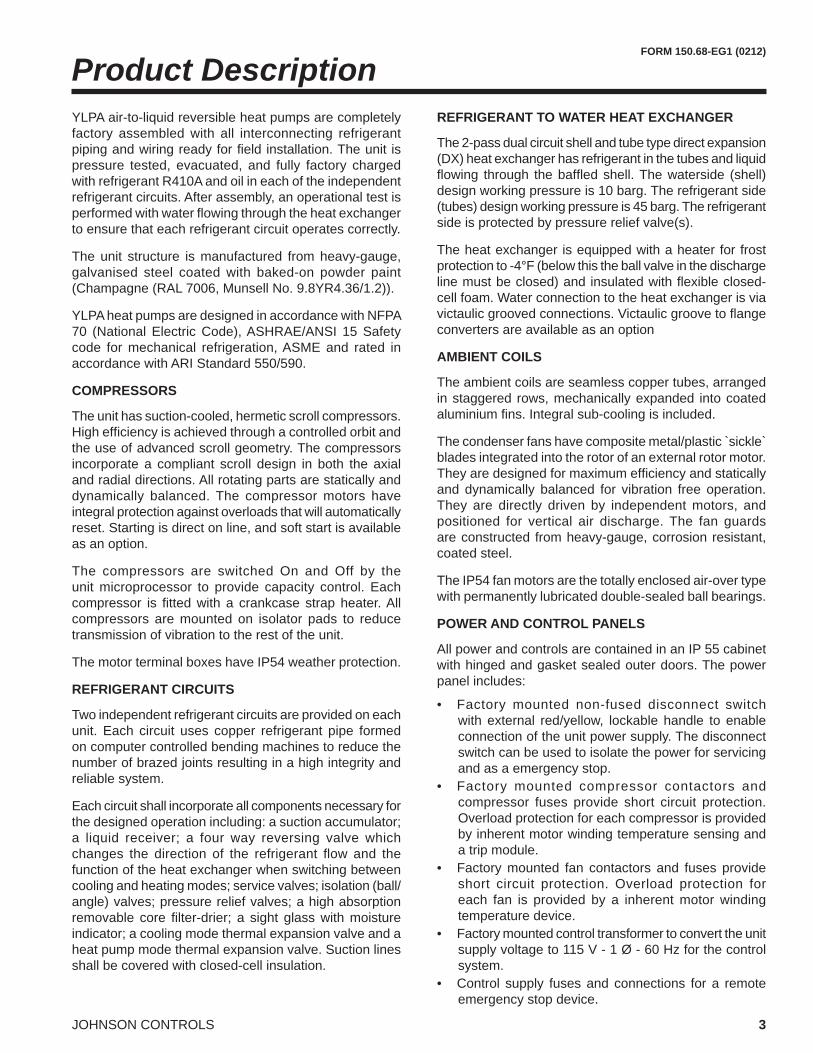
PIPEWORK ARRANGEMENT
The following are suggested pipework arrangements for single unit installations. For multiple unit installations, each unit should be piped as shown. These are recommendations of the Building Services Research Association.
Isolating Valve – Normally Closed
Flow Regulating Valve
Strainer
Pressure Tapping
Air vent
Flow Switch
Isolating Valve – Normally Open
CONNECTION TYPES AND SIZES
Standard pipework connections are of the Victaulic groove type.
For connection sizes relevant to individual models refer to the physical data tables in this manual.
WATER TREATMENT
The unit performance given in the Design Guide is based on a fouling factor of 0.0001 ft²hr°F/Btu. Dirt, scale, grease and certain types of water treatment will adversely affect the heat exchanger surfaces and therefore unit performance. Foreign matter in the water system(s) can increase the pressure drop, reducing the fl ow rate and causing potential damage.
Aerated, brackish or salt water is not recommended for use in the water systems. JCI recommends that a water
treatment specialist be consulted to determine whether the proposed water composition will not affect the heat exchanger materials of carbon steel and copper. The pH value of the water fl owing through the unit must be kept between 7 and 8.5.
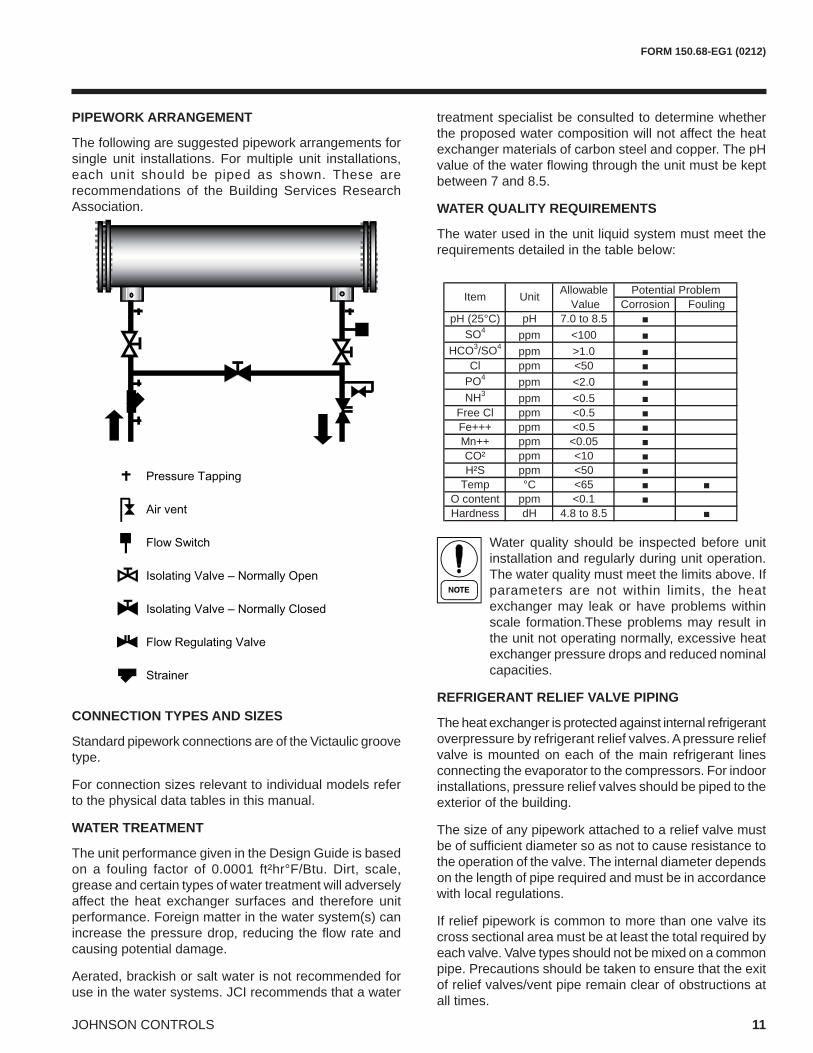
WATER QUALITY REQUIREMENTS
The water used in the unit liquid system must meet the requirements detailed in the table below:
Water quality should be inspected before unit installation and regularly during unit operation. The water quality must meet the limits above. If parameters are not within limits, the heat exchanger may leak or have problems within scale formation.These problems may result in the unit not operating normally, excessive heat exchanger pressure drops and reduced nominal capacities.
REFRIGERANT RELIEF VALVE PIPING
The heat exchanger is protected against internal refrigerant overpressure by refrigerant relief valves. A pressure relief valve is mounted on each of the main refrigerant lines connecting the evaporator to the compressors. For indoor installations, pressure relief valves should be piped to the exterior of the building.
The size of any pipework attached to a relief valve must be of suffi cient diameter so as not to cause resistance to the operation of the valve. The internal diameter depends on the length of pipe required and must be in accordance with local regulations.
If relief pipework is common to more than one valve its cross sectional area must be at least the total required by each valve. Valve types should not be mixed on a common pipe. Precautions should be taken to ensure that the exit of relief valves/vent pipe remain clear of obstructions at all times.
Temp °C <65 ■ ■O content ppm <0.1 ■Hardness dH 4.8 to 8.5 ■
Item Unit Potential Problem
JOHNSON CONTROLS12
FORM 150.68-EG1 (0212)
ELECTRICAL CONNECTION
The following connection recommendations are intended to ensure safe and satisfactory operation of the unit. Failure to follow these recommendations could cause harm to persons, or damage to the unit, and may invalidate the warranty.
No additional controls (relays, etc.) should be mounted in the control panel. Power and control wiring not connected to the control panel should not be run through the control panel. If these precautions are not followed it could lead to a risk of electrocution. In addition, electrical noise could cause malfunctions or damage the unit and its controls.
POWER WIRING
These units are suitable for 460 V, 3-phase, 60Hz nominal supplies only.
All electrical wiring should be carried out in accordance with local regulations. Route properly sized cables to the cable entries in the bottom of the power panel.
It is the responsibility of the user to install over current protection devices between the supply conductors and the power supply terminals on the unit.
To ensure that no eddy currents are set up in the power panel, the cables forming each 3 phase power supply must enter via the same cable entry.
All sources of supply to the unit must be taken via a common point of isolation (not supplied by JCI).
SINGLE POINT POWER SUPPLY WIRING
All models require one fi eld provided 460 V, 3Ø, 60 Hz + PE (Protected Earth) supply to the unit with circuit protection.
Connect the 3-phase supply to the non-fused disconnect switch located in the power panel using M12 lugs.
Connect the earth wire to the main protective earth terminal located in the power panel using a M10 lug.
CONTROL CIRCUIT TRANSFORMER
The control circuit transformer providing the 115 V, 1Ø, 50Hz supply to the unit control system is fi tted in a separate enclosure.
REMOTE EMERGENCY STOP DEVICE
If required, a remote emergency stop device may be wired into the unit. This device should be rated at 20 amps, 115V, AC-15. The device should be wired into terminals L and 5 in the power panel after removing the factory fi tted link.
CONTROL WIRING - VOLTAGE FREE CONTACT
All wiring to the voltage free contact terminal block requires a supply provided by the customer maximum voltage 115Vac, 24 Vdc.
The customer must take particular care deriving the supplies for the voltage free terminals with regard to a common point of isolation. Thus, these circuits when used must be fed via the common point of isolation so the voltage to these circuits is removed when the common point of isolation to the unit is opened. This common point of isolation is not supplied by JCI.
It is recommended that the customer wiring to these terminals uses orange wires. This will ensure that circuits not switched off by the units supply disconnecting device are distinguished by colour, so that they can easily be identifi ed as live even when the unit disconnecting devices are off. The YORK voltage free contacts are rated at 125 VA.
All inductive devices (relays) switched by the YORK voltage free contacts must have their coil suppressed using standard RC suppressors. If these precautions are not followed, electrical noise could cause malfunctions or damage to the unit and its controls.
Chilled Liquid Pump Starter
Terminals 23 and 24 close to start the liquid pump. This contact is closed if there is a ‘Leaving Liquid Temperature Cutout’ or any of the compressors are running or the daily schedule is not calling for a shutdown with the unit switch on.
The contact must be used to ensure that the pump is running in the event of a ‘Leaving Liquid Temperature Cutout’.
The pump contact will not close to run the pump if the unit has been powered up for less than 30 seconds, or if the pump has run in the last 30 seconds, to prevent pump motor overheating.
Run Contacts
Terminals 25 and 26 close to indicate that refrigerant system 1 is running and terminals 27 and 28 close to indicate that refrigerant system 2 is running.
Application Data - continued
FORM 150.68-EG1 (0212)
13JOHNSON CONTROLS
Alarm Contacts
Each refrigerant system has a voltage-free normally open contact that will close when control power is applied to the panel, if no fault conditions are present. When a fault occurs which locks a system out, or there is a power failure the contact opens. To obtain a system alarm signal, connect the alarm circuit to terminals 29 and 30 for No. 1 system and terminals 31 and 32 for No. 2 system.
Control Wiring - System Inputs
All wiring to the control terminal block (nominal 30 Vdc) must be run in screened cable, with the screen earthed at the panel end only. Run screened cable separately from mains cable to avoid electrical noise pick-up.
The voltage free contacts must be suitable for 30 Vdc (gold contacts recommended). If the voltage free contacts form part of a relay or contactor, the coil of the device must be suppressed using a standard RC suppressor. The above precautions must be taken to avoid electrical noise that could cause a malfunction or damage to the unit and its controls.
Flow Switch
A chilled liquid flow switch of suitable type must be connected to terminals 13 and 14 to provide adequate protection against loss of liquid fl ow.
Remote Start/Stop
Connect a remote switch to terminals 13 and 51 to provide remote start/stop control if required.
Remote Mode Selection
Remote mode selection can be accomplished by connecting a contact between terminals 13 and 50. With the contact open the unit is in the cooling mode, with the contact closed the unit is in the heating mode.
Remote Reset of Chilled Liquid Setpoint
The PWM input (terminals 13 and 20) allows reset of the chilled liquid setpoint by supplying a ‘timed’ contact closure.
Remote Load Limiting
Load limiting prevents the unit from loading beyond a desired value. The unit % load limit depends on the number of compressors on the unit. The load limit inputs to terminals 13 and 21 work in conjunction with the PWM input to terminals 13 and 20.
Fan Full Speed Inhibit
To reduce unit noise the fans can be limited to run at a maximum step of all fans in star (reduced speed) i.e. fan full speed is inhibited. Connect a customer voltage free contact to terminals 13 & 15.
EMS Analogue Input
Provides a means of resetting the leaving chilled or hot liquid temperature from the BAS/EMS. Accepts 4 to 20 mA, 0 to 20 mA, 0 to 10 Vdc or 2-10 Vdc. Connect to terminal A+ and A-.
Modbus, BACnet MS/TP and N2
Enable communications with building protocol systems using Modbus, BACnet or N2 protocol. Connect through standard RS485 port.
Water Pressure DropRefrigerant to Water Heat Exchanger Pressure Drop Graph
Pre
ssur
e D
rop
(ft H
2O)
100
Flow Rate (gpm)
200 300 600400 10008003
5
10
15
20
30
40
50
60
80
0170SE
0115SE0145SE
JOHNSON CONTROLS16
FORM 150.68-EG1 (0212)
RatingsPERFORMANCE DATA - COOLING
Rated in accordance with AHRI Standard 550/590 based on sea level altitude, evaporator fouling factor of 0.0001°F-ft²h/Btu, evaporator temperature drop of 10°F, and 2 pass evaporator confi guration.
NOTES:1. COMP kW = Compressor Input Power2. EER = Heat Pumps EER (includes power from compressors, fans, and the control panels 0.8 kW)3. LCWT = Leaving Chilled Water Temperature4. Ratings are based upon 2.4 GPM evaporator water per ton and 0.0001 fouling factor5. Rated in accordance with ARI Standard 550/590
46
45
44
42
50
48
46
45
44
42
40
50
48
95IPLV
AIR TEMPERATURE ON - CONDENSER (°F)
IPLV 105 110 115
AIR TEMPERATURE ON - CONDENSER (°F)
YLPA MODEL
100
40
90YLPA MODEL
75 80 85LCWT(°F)
LCWT(°F)
FORM 150.68-EG1 (0212)
17JOHNSON CONTROLS
PERFORMANCE DATA - PART LOAD
Rated in accordance with AHRI Standard 550/590 based on sea level altitude, evaporator fouling factor of 0.0001°F-ft²h/Btu, evaporator temperature drop of 10°F, and 2 pass evaporator confi guration.
Rated in accordance with AHRI Standard 550/590 based on sea level altitude, evaporator fouling factor of 0.0001°F-ft²h/Btu, evaporator temperature drop of 10°F, and 2 pass evaporator confi guration.
NOTES:1. COMP kW = Compressor Input Power2. COP = Heat Pumps COP (includes power from compressors, fans, and the control panels 0.8 kW)3. LHWT = Leaving Hot Water Temperature
120
125
130
95
100
105
110
113
115
LHWT(°F)
YLPA MODEL
AIR TEMPERATURE ON - CONDENSER (°F)44 50 55 60
Ratings - continued
FORM 150.68-EG1 (0212)
19JOHNSON CONTROLS
Technical DataOPERATING LIMTATIONS
PHYSICAL DATA
Min. Max. Min. Max. Min. Max.
Liquid Outlet Temperature (Water) °FLiquid Outlet Temperature Range (T) °FAir Temperature - Standard Unit °FLiquid Outlet Temperature (Water) °FLiquid Outlet Temperature Range (T) °FAir Temperature - Standard Unit °F
gpm 181 700 181 700 200 850
ftH2O 5.4 43.0 5.4 43.0 3.4 55.4
psipsi
V
(1) Unit may operate unloaded up to 125ºFdepending on model size and site conditions.(2) Tolerance +/-10%
Power Supply Voltage (2)
Heating Mode
Maximum Refrigerant Side Pressure
Heat Exchanger Flow Rate
Maximum Water Side PressureHeat Exchanger Presssure Drop
0115SE 0145SE 0170SENumber of refrigerant circuitsRefrigerant Charge (1) System 1 / System 2 lb 130 / 137 181 / 132 181 / 181Oil Charge System 1 / System 2 lb 24.2 / 24.2 37.4 / 24.2 37.4 / 37.4
Number of compressors 2 / 2 3 / 2 3 / 3TypeNumberTypeWater Volume l 600Water Connections inchNumber of Fans (circuit 1 / circuit 2) 4 / 4 6 / 4 6 / 6Total Air Flow - Standard Models m3/s 47 58 70Length inch 194.4 230.5 274.4Width inch 88.4 88.4 88.4Height inch 94.1 94.1 94.1Shipping Weight lb 9811 11243 12124Operating Weight lb 10472 11904 13447
(1) Liquid sub-cooling measured at the liquid line should be between 47.3 and 52.0°F at circuit full load. Sub-cooling is determined by the level of refrigerant charge in each system