Modular Media Converter (MMC) Quick Reference Parts List Before you begin the installation of the MMC you will need the following items. Included items: Populated MMC chassis AC power cord, included if AC power supply is used DC connector cables, if DC power supply is used Front and rear rack mount brackets Rack mount bracket screws (22 included) 1 M4 grounding nut Other required items (not included): Phillips screwdriver 8 rack mount screws Crossover cable long enough to connect the BNP and the management workstation Workstation for configuration 1 or more Gigabit Ethernet copper or optical SFP modules • • • • • • • • • • • Rack Mount the MMC Using the provided screws, attach the front rack mount bracket to one side of the chassis, then attach the rear rack mount bracket. Repeat on the other side of the chassis. Secure the front of the chassis to the rack. Connect the rear rack mount extensions between the rear rack mount brackets and the rack. Slide the mounting brackets to the correct distance and secure them. Ground the chassis. 1. 2. 3. Connect the Ports Use the correct cable for the port type and your network configuration: 10/100BaseT Gigabit Ethernet port, used to communicate with an external console. ASI ports, located on the rear of the chassis. Use a push/twisting motion to ensure proper seating of the cables, shown in closeup. The Gigabit Ethernet ports must have approved SFPs installed before cabling. • • • The MMC can be configured with up to four ASI modules with six ports each. Slot C rear of chassis Port# 1 2 3 4 5 6 Slot D Slot A Slot B Recommended SFPs Tyco 1382392-3: Multi mode 850 nm, 1 GigE, LC Optical transceiver 1511094-3: Single mode 1310 nm, 1 GigE, LC Optical transceiver Finisar FCMJ-8521-3: Active copper SFP FTRJ1319P1BTL: Single mode 1310 nm, 1GigE, LC optical transceiver FTRJ8519P1BTL: Multi mode 850 nm, 1GigE, LC optical transceiver Copyright 2006 RGB Networks. All rights reserved. Start Here 1 2 3 Install recommended SFPs according to the manufacturer’s instructions. 4 Steps to Installing and Configuring the MMC Attach the rear mounting bracket to the MMC chassis (A) and then to the rack (B) A B Attach the MMC chassis to the front of the rack Rear of MMC (AC power shown) Front of MMC ASI Ports GigE Ports
Transcript
Modular Media Converter (MMC) Quick Reference
Parts ListBefore you begin the installation of the MMC you will need the following items.Included items:
Populated MMC chassisAC power cord, included if AC power supply is usedDC connector cables, if DC power supply is usedFront and rear rack mount bracketsRack mount bracket screws (22 included)1 M4 grounding nut
Other required items (not included):Phillips screwdriver8 rack mount screwsCrossover cable long enough to connect the BNP and the management workstation Workstation for configuration 1 or more Gigabit Ethernet copper or optical SFP modules
••••••
•••
••
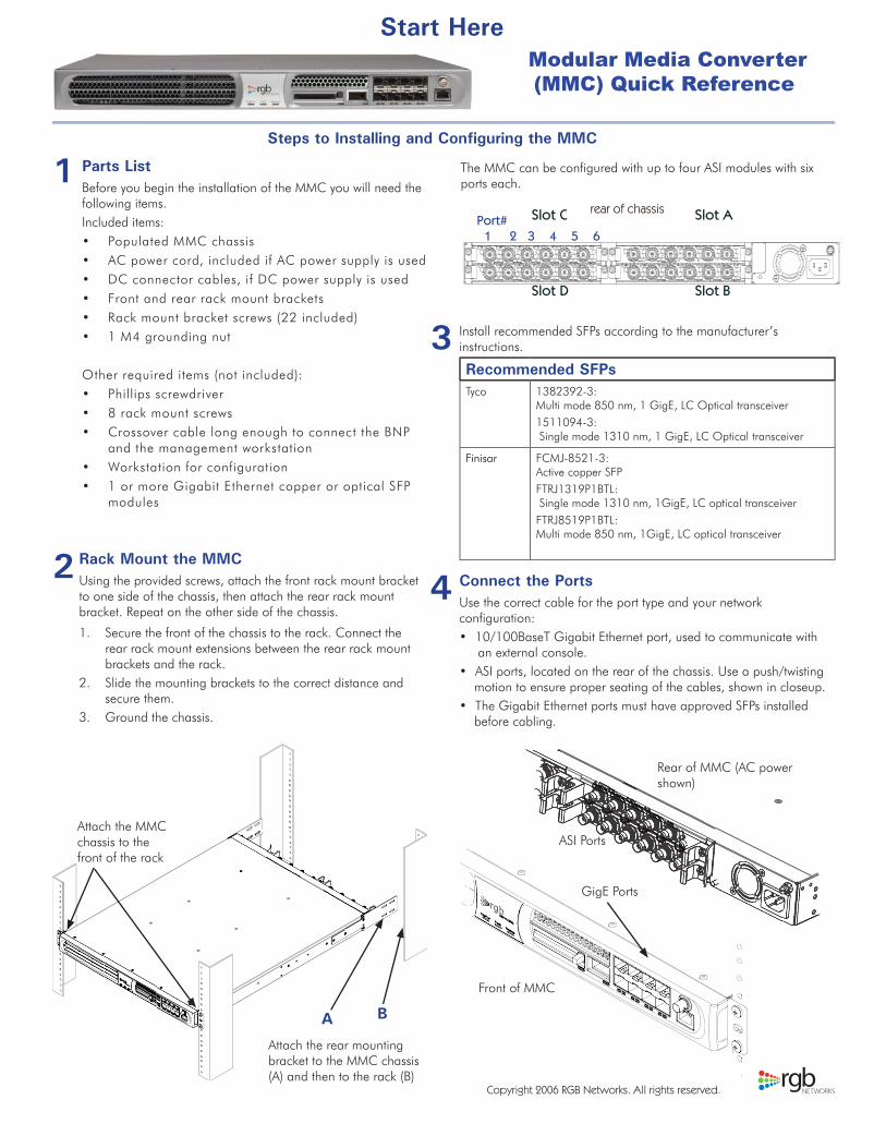
Rack Mount the MMCUsing the provided screws, attach the front rack mount bracket to one side of the chassis, then attach the rear rack mount bracket. Repeat on the other side of the chassis.
Secure the front of the chassis to the rack. Connect the rear rack mount extensions between the rear rack mount brackets and the rack.Slide the mounting brackets to the correct distance and secure them.Ground the chassis.
1.
2.
3.
Connect the PortsUse the correct cable for the port type and your network configuration:
10/100BaseT Gigabit Ethernet port, used to communicate with an external console.
ASI ports, located on the rear of the chassis. Use a push/twisting motion to ensure proper seating of the cables, shown in closeup.
The Gigabit Ethernet ports must have approved SFPs installed before cabling.
•
•
•
The MMC can be configured with up to four ASI modules with six ports each.
Slot C rear of chassisPort# 1 2 3 4 5 6
Slot D
Slot A
Slot B
Recommended SFPsTyco 1382392-3:
Multi mode 850 nm, 1 GigE, LC Optical transceiver1511094-3: Single mode 1310 nm, 1 GigE, LC Optical transceiver
Finisar FCMJ-8521-3: Active copper SFPFTRJ1319P1BTL: Single mode 1310 nm, 1GigE, LC optical transceiverFTRJ8519P1BTL: Multi mode 850 nm, 1GigE, LC optical transceiver
Copyright 2006 RGB Networks. All rights reserved.
Start Here
1
2
3 Install recommended SFPs according to the manufacturer’s instructions.
4
Steps to Installing and Configuring the MMC
Attach the rear mounting bracket to the MMC chassis (A) and then to the rack (B)
A B
Attach the MMC chassis to the front of the rack
Rear of MMC (AC power shown)
Front of MMC
ASI Ports
GigE Ports
Rebooting the MMCThe MMC can be rebooted through a power cycle or using the Element Manager application.
To power the unit down, disconnect the power cable from the connector. To reboot the MMC from the Element Manager application, select Maintenance > Reboot, then click Apply Reboot.
•
•
GigE Port ConfigurationSelect Configuration > GigE Control Port Configuration.Configure the ports by enabling the port and providing the IP address, subnet, and gateway for each.Repeat for each port and click Apply.
Global ConfigurationSelect Configuration > Global Chassis Configuration.Enter the necessary settings and click Apply.
1.2.
Element ManagerThe Element Manager requires JRE v1.5 or higher. You can install JRE from Sun’s web site or from the included product CD.To launch the Element Manager:
Open a browser session on the management workstation.Enter the IP address of the MMC into the browser’s address field. The default IP address is 10.1.1.1. Click Launch Element Manager. Enter the IP Address of the MMC. Select your user account and enter the corresponding password.
1.2.
3.4.
Parameter Value
Input Power AC: 100-127 VAC @ 1.4A to 200-240 VAC @ 0.8ADC: 48VDC @ 3.5A (range 36-75VDC)
Line frequency 50Hz to 60Hz
Power Consumption 170 W maximum (fully loaded)
Dimensions 1 rack unit - 1.75” H x 19” W x 23” L(43.6 H x 433 W x 583 L mm)
Weight <30 lbs (11.34 kg)
Env. Condition Limitation
Storage Temp -40° to 70° C (-40° to 158° F)
Operating Temp 0° to 40° C (32° to 104° F)
Humidity 5% to 95% (non-condensing)
Power UpConnect all ports before applying power. Locate the included AC power cable and plug one end into the MMC power connector. Plug the other end of the power cable into the input power source. The unit should now have power and the Cfg/Pwr LED turns solid green. For DC power, cut the provided DC connector cables to the correct length to reach the MMC from the power source. Attach the connector cables from the power source to the BNP power connectors. Attach the other end of the power connector cables into the input power source. Toggle the external circuit breaker to the ON position.The unit should now have power and the Cfg/Pwr LED turns solid green.
Cfg/Power Backup
Fault
Compact flash 10 GigE Port/SFP Fast Ethernet
LEDs
5
7
9
Rev. G
8 Ethernet Control Port ConfigurationSelect Configuration > Ethernet Port Control.Enter the necessary settings and click Apply.
1.2.
6
10
Configuration Mapping1. Select Configuration > ASI Port.2. Drag and drop the ports and transport streams from ASI to GigE ports and vice versa, as desired, or use the right- click menus to perform other tasks.
11
SNMP Configuration1. Select Configuration > SNMP.2. Enter the SNMP settings and click Apply.


![Modular Multilevel Submodules for Converters, from the ... · Modern HVDC Transmission – MMC [M²C] = Modular concept based on power electronic building blocks modular converter](https://static.documents.pub/doc/80x56/5ea641f2a0779206f824b607/modular-multilevel-submodules-for-converters-from-the-modern-hvdc-transmission.jpg)


