CCN: Lecture Notes Computer Comm. & Networking 1 Module 2 Computer Networking A specific and very important application of data communications is computer networking. We need to examine what topologies and protocols a computer network may employ.
Transcript
CCN: Lecture Notes Computer Comm. & Networking 1
Module 2
Computer Networking
A specific and very important application of data communications is computer networking.
We need to examine what topologies and protocols a computer network may employ.
CCN: Lecture Notes Computer Comm. & Networking 2
Local Area Networks (LAN)-Topologies
Many nodes usually require high data transfer rates, and ability to connect to any other node within close proximity of each other.
How do we connect the nodes together?
What kinds of topologies we can use?
• Star
• Ring
• Bus
• Hub/Tree
CCN: Lecture Notes Computer Comm. & Networking 3
Star
• Uses large amount of cable
• Outage of node connection does not affect others
• Center or hub failure -> all nodes outage
CCN: Lecture Notes Computer Comm. & Networking 4
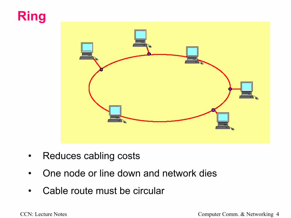
Ring
• Reduces cabling costs
• One node or line down and network dies
• Cable route must be circular
CCN: Lecture Notes Computer Comm. & Networking 5
Bus
• Further reduced cabling costs
• Non circular route
• One node down, rest still work
• Interconnected via bridges
CCN: Lecture Notes Computer Comm. & Networking 6
Hub/Tree
• Hub is bus/ring with all wiring inside one box
• Cross between star and bus/ring
• Can be combined into trees
CCN: Lecture Notes Computer Comm. & Networking 7
LAN-MediaBaseband systems
A baseband system sends digital signals straight to line. They may be encoded (e.g. Manchester code) but they are notmodulated.
What is Baseband?
The original frequency band of the message signal, usually from (near) dc to a few megahertz.
Examples of Baseband transmission systems
⇒ LANS (ethernet, token ring)
⇒ RS232C
⇒ Magnetic discs and tapes
CCN: Lecture Notes Computer Comm. & Networking 8
A Typical Baseband System
Sampler CoderQuantizer
Format
AnalogInformation
WaveformEncoder(modulator)
DigitalInformation
Low-passfilter Decoder Waveform
Detector
AnalogInformation
DigitalInformation
Transmitter
Channel
Receiver
Format
BinaryDigits
PulseWaveforms
Source
Destination
CCN: Lecture Notes Computer Comm. & Networking 9
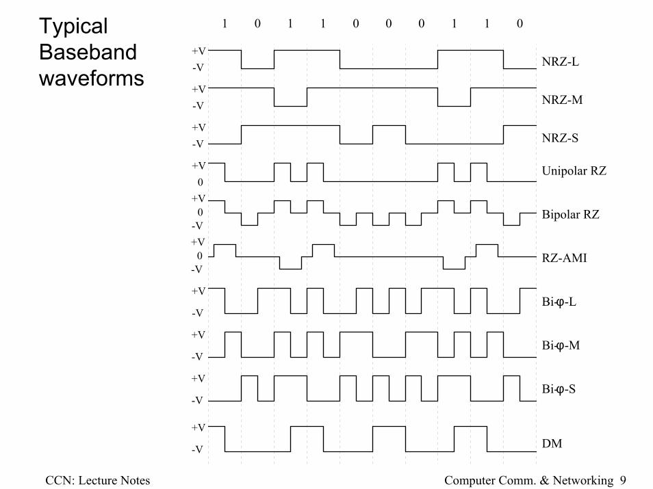
TypicalBaseband waveforms
1 0 1 1 0 0 0 01 1
NRZ-L
NRZ-M
NRZ-S
Unipolar RZ
Bipolar RZ
RZ-AMI
Bi- -Lφ
Bi- -Mφ
Bi- -Sφ
DM
+V-V
+V-V
+V-V
+V0
-V
+V0
-V
+V0
+V
-V
+V
-V
+V
-V
+V
-V
CCN: Lecture Notes Computer Comm. & Networking 10
When selecting a coding scheme, one should consider the following:1. DC component
System which requires AC coupling cannot use those schemes that contain DC component. E.g. Unipolar NRZ
2. Self-clockingSome schemes have inherent clocking features which permit clock recovery at the receiving end. E.g. Manchester, bipolar-RZ
3. Error detectionSome schemes provide error correction capabilities without additional parity bits.
4. BandwidthCommunication channels are usually band limited. One has to consider the bandwidth efficiency of the coding scheme.
5. Noise immunitySome schemes are more immune to noise than others.
CCN: Lecture Notes Computer Comm. & Networking 11
Twisted wire
• Shielded and unshielded
• Flexible, i.e., easy to install
• Normally used for
• Low grade star networks
• Hub-DTE connections
• Network drop*
• Low to medium data rates
CCN: Lecture Notes Computer Comm. & Networking 12
Thin wire
• ≈ 0.25″ coaxial cable , i.e., RG58
• Less flexible
• High data rates
• Used as bus or ring cable
• Used as drop* from network
CCN: Lecture Notes Computer Comm. & Networking 13
Thick wire
• ≈ 0.5″ coaxial cable
• Rigid, i.e., hard to run
• High data rates
• Used as bus, ring or backbone cable
CCN: Lecture Notes Computer Comm. & Networking 14
Optical Fibre• Rigid
• Very high data rates
• Used as bus, ring or backbone
Wireless• Infrared at 850 and 950nm
• Spread spectrum modulated on 2.4 GHz ISM band
• Mainly office networks, store inventory etc.
• Generally moderate bit rates but portable
CCN: Lecture Notes Computer Comm. & Networking 15
*Network dropsBecause of the frequency of the signals used, care must be taken to avoid reflections due to impedance mismatches.
• Cable ends must be terminated
Attach resistor across last node
• Tees must be avoided
Problem when DTE is not close to cable
Use a transceiver to connect onto the cable
Receives and transmits signal onto cable directly
Converts signal into a form suitable for drop cable and DTE connection (Ethernet card in PC)
Transceivers and DTE connections may connect via same signals as main cable or via twisted pairs through an Attachment Unit Interface (AUI)
A popular system is an adaptation of the Community Antenna Television System (CATV).
The system is very similar to using a modem on a PSTN (Public Switched Telephone Network) line except the carrier may be 100’s MHz with a B/W of MHz’s
CCN: Lecture Notes Computer Comm. & Networking 17
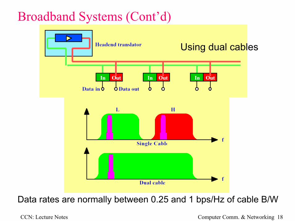
Broadband Systems (Cont’d)Forward and reverse directions may be accomplished by different frequencies on a single cable or by using dual cables
Using a single cable
Headend amplifiers retransmit the received signal onto the transmit frequency or onto the transmit cable
CCN: Lecture Notes Computer Comm. & Networking 18
Broadband Systems (Cont’d)
Using dual cables
Data rates are normally between 0.25 and 1 bps/Hz of cable B/W
CCN: Lecture Notes Computer Comm. & Networking 19
Cable B/W’s of up to 400MHz are common.
Connection are either
• DedicatedFrequency band assigned to 2 nodes permanently≈ 20 Mbps
• SwitchedFrequency agile modems switch to a designated frequencyFrequencies assigned from a common frequency≈ 56 Mbps
• Multiple AccessTime division accessEach node gets the entire B/W for a short time and addresses a packet to another node.Most popular
CCN: Lecture Notes Computer Comm. & Networking 20
How do the different mediums perform under the different topologies?Ring
CCN: Lecture Notes Computer Comm. & Networking 21
How do the different mediums perform under the different topologies?Bus/Tree
CCN: Lecture Notes Computer Comm. & Networking 22
How do the different mediums perform under the different topologies?Star
CCN: Lecture Notes Computer Comm. & Networking 23
How is access of each node to the media controlled?
Common Medium Access Control (MAC) protocols
Will see later that MAC forms bottom half of Link Layer
• Carrier Sense Multiple Access/Collision Detect (CSMA/CD)
• Control token
CCN: Lecture Notes Computer Comm. & Networking 24
CSMA/CD• Sole application to bus networks
• All nodes connected together onto bus
Multiple access (MA)
• Data is broadcast onto the bus in a packet with a header containing the destination address
• Packet also contains source address
• Before a frame is sent, the node listens to see if the bus is busy (Carrier Sense CS)
• When the bus is quiet, the node will transmit
• Even though the bus is quiet at the listening node, a data framemay still be on its way
• When it arrives a collision will occur
CCN: Lecture Notes Computer Comm. & Networking 25
CSMA/CD (Cont’d) • A collision may be detected by listening to your own
transmission (Collision detect CD).
• When what you hear on the bus is not the same as what you are sending, a collision may be in progress.
• When a collision occurs, the transmitting node sends a jam sequence of some bit sequence to ensure the other node involved in the collision detects the collision.
• Both nodes then cease transmission and back-off for a random time.
• Either one of these nodes or another node may attempt to transmit again.
• Collision rate is purely probabilistic.
CCN: Lecture Notes Computer Comm. & Networking 26
CSMA/CD (Cont’d)
Concept of collision window
CCN: Lecture Notes Computer Comm. & Networking 27
How is access of each node to the media controlled?
Common Medium Access Control (MAC) protocols
Will see later that MAC forms bottom half of Link Layer
• Carrier Sense Multiple Access/Collision Detect (CSMA/CD)
• Control token
CCN: Lecture Notes Computer Comm. & Networking 28
Control token• The token is just a special frame that gives a node permission to
transmit when it receives it.
• All nodes are placed in a logical ring• Not necessarily a physical ring
• All nodes are placed in a sequence
• The token is passed from node to node around the logical ring
• A node may transmit a frame when it receives the token.
• The node then sends the token to the next logical node
• One node is generally designated to attend to initialisation of the token and regeneration of a lost token
• A physical ring may be employed in which case the nodes will be 2 port devices.
CCN: Lecture Notes Computer Comm. & Networking 29
Slotted ring• A physical ring contains normal nodes plus a monitor node.
• The monitor node ensures there are a fixed number of empty frames being circulated around the ring.
• The frames contain a full/empty bit to indicate their status.
CCN: Lecture Notes Computer Comm. & Networking 30
Slotted ring (cont’d)
• When a node wishes to transmit, it fills an empty frame with source and destination address and data, and it switches the full/empty bit.
• The now full frame will circulate around the ring and will be absorbed by the destination node who will modify the response bits to indicate it has read the frame.
• The frame will continue around the ring until it reaches the source node who will check the response bits and mark the frame as empty (full/empty bit).
• The monitor also checks a passed bit which it resets each time a full frame passes.
• If a node fails to mark an old frame as empty, the monitor will detect this and mark the frame empty.
CCN: Lecture Notes Computer Comm. & Networking 31
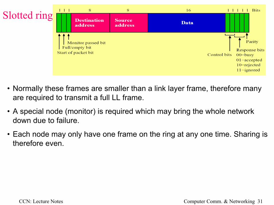
Slotted ring (cont’d)
• Normally these frames are smaller than a link layer frame, therefore many are required to transmit a full LL frame.
• A special node (monitor) is required which may bring the whole network down due to failure.
• Each node may only have one frame on the ring at any one time. Sharing is therefore even.
CCN: Lecture Notes Computer Comm. & Networking 32
Ring network problem• Timing jitter
The received signal will contain clocking information (e.g., Manchester encoding)
Effects such as delay distortion, noise and receiver imperfections will cause the clock extraction to be less than perfect.
The node may received the data correctly but it will retransmit the data with the imperfections.
The next node will add more imperfections.
Errors may eventually occur due to this additive timing jitter
• Robustness and installation
If the cable is broken, the whole network fails.
Adjacent nodes may need to be physically identified during installation.
A physical ring must be cabled.
CCN: Lecture Notes Computer Comm. & Networking 33
Bus vs. Ring • For large installations and high capacity, a bus system will be most suited.
• For moderate capacity and size, the particular application must be examined.
Bus is simple, i.e., passive taps.
Ring uses point to point communications
— Data regenerated at each node
— Therefore grater distances at lower Pε
Bus has cascaded amps
— Can do same distance at greater Pε
Ring may use optical fibre
— Very high data rates
— Low electromagnetic interference (EMI)
CCN: Lecture Notes Computer Comm. & Networking 34
Network Standards in Use Today
The closed system standards were examined by IEEE who developed a set of standards which were adopted by ISO.
The common networking standards are IEEE 802 series.
CCN: Lecture Notes Computer Comm. & Networking 35
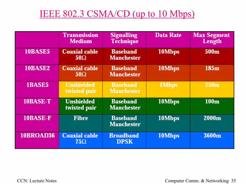
IEEE 802.3 CSMA/CD (up to 10 Mbps)
CCN: Lecture Notes Computer Comm. & Networking 36
IEEE 802.3 CSMA/CD (Fast Ethernet)
NRZI NRZ but transition at beginning of bit time indicates a 1
4B5B 4 bits are encoded as 5 bit code to ensure transitions at least every 2 bits
8B6T 8 bits 6 trits, each 8 binary bits are converted into 6 trinary bits (3 levels)
100BASET4 Transmits on 3 pairs and receives on 4 (33.3 Mbps data rate)
CCN: Lecture Notes Computer Comm. & Networking 37
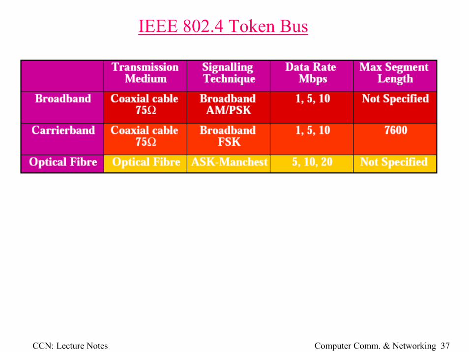
IEEE 802.4 Token Bus
CCN: Lecture Notes Computer Comm. & Networking 38
IEEE 802.5 Token Ring
Fibre Distributed Data Interface-FDDI (variation on 802.5)
CCN: Lecture Notes Computer Comm. & Networking 39
IEEE 802.3 CSMA/CDCommonly called Ethernet (Thick wire) or Cheapernet(Thin wire).
• A tap connects the DTE onto the cable.
• Transceiver is integrated with tap for thick wire.
• Transceiver is found in DTE for thin wire.
• A twisted wire drop interface connects to the DTE controller board.
• A transceiverSends and receives the baseband signal.Detects collisionsProvides electrical isolationPrevents transmission malfunctions (jabber)
CCN: Lecture Notes Computer Comm. & Networking 40
IEEE 802.3 CSMA/CD (cont’d)
Jabber control prevents the transmitter from transmitting onto the cable due to a fault condition.
CCN: Lecture Notes Computer Comm. & Networking 41
IEEE 802.3 CSMA/CD (cont’d)A CSMA/CD coaxial Ethernet may be accessed via a twisted wire hub (10BASE-T). [Experiment]
The hub combines a number of DTE’s connected with 10BASE-T (2 twisted wire pairs, IN and OUT) to the coaxial cable.
Collisions now occur at the point where the hub connects to the coax. The collision is detected still at the DTE.
Adaptive echo cancellation techniques are required to prevent crosstalk problems due to the unshielded twisted pair.
MAC→
CCN: Lecture Notes Computer Comm. & Networking 42
Frame formatThe MAC unit encapsulates the data into a frame.
• A certain number of retries are allowed, called the attempt limit (16)
• Collisions occur in the collision window which is the period for a frame to reach the farthest part of the network and return.
• This period (TP) has a safety margin added and becomes the slot time.
Slot time = 2×TP + safety margin
• The backoff time for the nth retry is calculated as R where
0≤R≤2k and k = min(n, backoff limit)
(backoff limit = 10)
CCN: Lecture Notes Computer Comm. & Networking 44
IEEE 802.3 frame (cont’d)
CCN: Lecture Notes Computer Comm. & Networking 45
IEEE 802.5 Token RingA token ring network is a LAN technique based on a token passingprotocol for media access control
It can be a logical ring using a physical ring or a physical star topology
CCN: Lecture Notes Computer Comm. & Networking 46
IEEE 802.5 Token RingOperation has been examined already, two variations exist.
Normal token release• When a node transmits a frame it waits until the frame comes back
around the ring and removes the frame from the ring. It then transmit the token—pass it to the next node.
Early token release• Instead of waiting for the frame to return and be stripped from the ring,
the node retransmits the token straight after the frame is transmitted. This allows much greater throughput.
Connection to the medium is via a Trunk Coupling Network (TCN) by either direct connection or through a concentrator.
CCN: Lecture Notes Computer Comm. & Networking 47
IEEE 802.5 Token Ring (cont’d)Connection to the medium is via a Trunk Coupling Network (TCN) by either direct connection or through a concentrator.
Concentrator (Repeater) regenerate and propagate a signal. It is used to extend the length of the LAN
CCN: Lecture Notes Computer Comm. & Networking 48
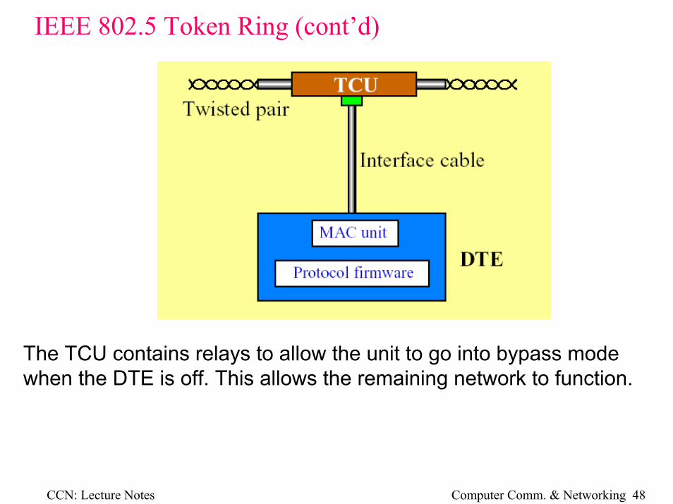
IEEE 802.5 Token Ring (cont’d)
The TCU contains relays to allow the unit to go into bypass modewhen the DTE is off. This allows the remaining network to function.
CCN: Lecture Notes Computer Comm. & Networking 49
IEEE 802.5 Token Ring (cont’d)
When the node is connected, it may be in either listen or transmit mode. The former will normally produce a one bit delay through the device.
MAC functions• Frame encapsulation and de-encapsulation• FCS generation• Error detection• Implementation of MAC algorithm• Clock extraction
CCN: Lecture Notes Computer Comm. & Networking 50
IEEE 802.5 Token Ring (cont’d)
Latency of the ring is the time for a token to do one lap of an idle ring.
The ring must have a minimum latency of at least the time to transmit the token (24 bits). Otherwise the head of the token will overlap the tail.
The monitor node has a buffer to ensure this. The node may very the size of this buffer to increase or decrease bit rates due to erroredclock extraction.
For 24 bit token, the buffer is set 27 so it may very up and down.
CCN: Lecture Notes Computer Comm. & Networking 51
IEEE 802.5 Token Ring Frame formats
Token frame
At the data link layer, a token frame circulates around the ring when all nodes are idle
• SD and ED have bit violations (J,K) in Manchester code to make them unique as delimiter.
• In token, I and E are both 0.• AC contains
— P priority bits describing tokens priority— T token identification bit— M monitor bit so monitor can detect old frames— R reservation bits so node may request a high priority token
• E set by DTE if it detects an error• I indicates first or intermediate frame (1=first/inter, 0=last)
CCN: Lecture Notes Computer Comm. & Networking 52
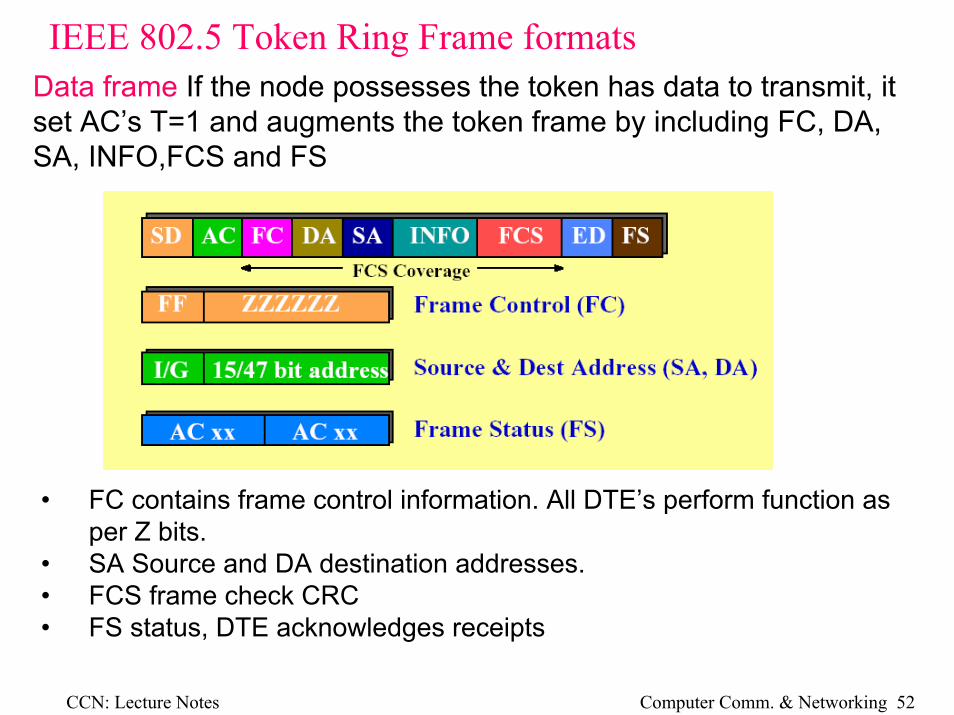
IEEE 802.5 Token Ring Frame formatsData frame If the node possesses the token has data to transmit, it set AC’s T=1 and augments the token frame by including FC, DA, SA, INFO,FCS and FS
• FC contains frame control information. All DTE’s perform function as per Z bits.
• SA Source and DA destination addresses.• FCS frame check CRC• FS status, DTE acknowledges receipts
CCN: Lecture Notes Computer Comm. & Networking 53
IEEE 802.5 Token Ring (priority)Token and frames are assigned 8 levels of priority to speed up important frame transmission (P bits in AC)
Pr = received priorityPm = priority of message to be transmittedRr = received reservation
• A node wish to transmit must wait for a free token with Pr≤ Pm.• While waiting, a node may reserve a future token at level Pm• To do this, it sets Rr ← Pm in a passing data frame if Rr < Pm, or
sets Rr ← Pm in a passing token frame if Rr < Pm and Pm < Pr• After transmission, the token is passed on with priority set the max
of Rr, Pm and Pr. Reservation is set to the max of Rr, Pm. • This forces priority higher and higher. To cure this the node that
upgraded the priority must downgrade it when high priority traffic is finished.
CCN: Lecture Notes Computer Comm. & Networking 54
IEEE 802.4 Token BusA token bus network has a logical ring on a physical bus
• A token bus network physically resembles a bus topology; logically, it is a ring.
• A token is transmitted from lobe to lobe using network addresses and occurs in descending order.
• The lobe that possesses the token is permitted to transmit data.The lobe order in the figure is 70-59-44-32-23-16-8.
Example
CCN: Lecture Notes Computer Comm. & Networking 55
IEEE 802.4 Token Bus
Node 44 has the token and want to send data to 70.• It places the data frame on the bus, broadcasts to all nodes to
hear.• Only 70 reads and processes the data.• After transmission, 44 pass the token to 32Data transmission – similar to IEEE802.3 (broadcasting)MAC – similar to IEEE802.5 (ring)
CCN: Lecture Notes Computer Comm. & Networking 56
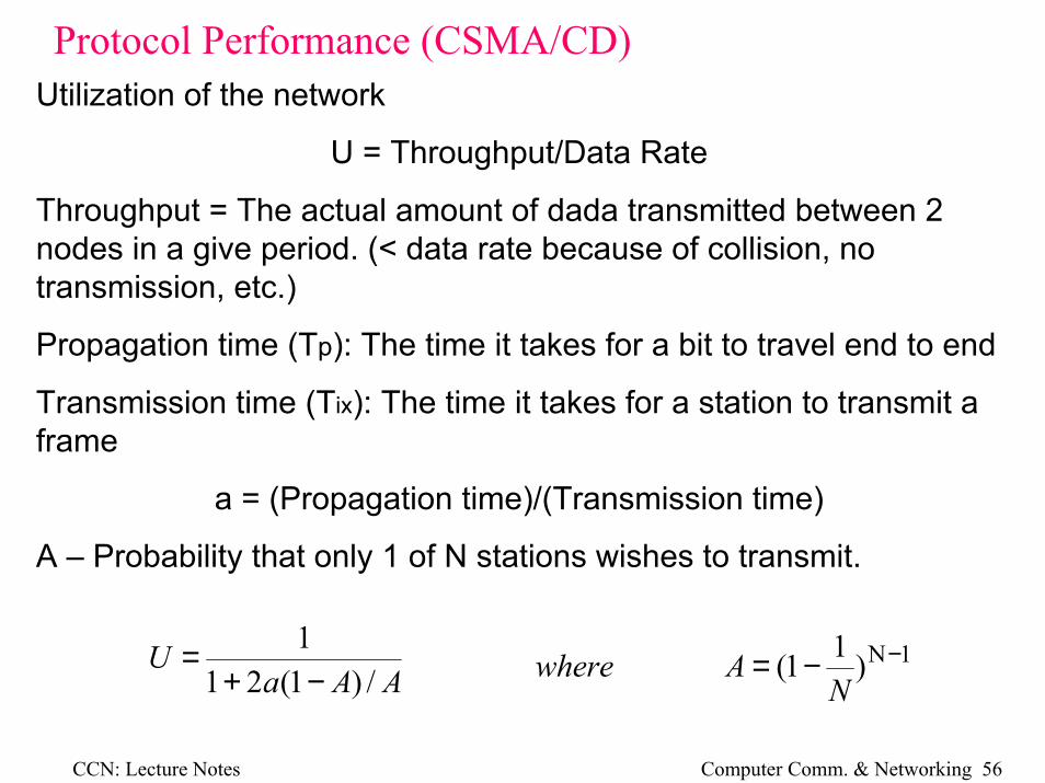
Protocol Performance (CSMA/CD) Utilization of the network
U = Throughput/Data Rate
Throughput = The actual amount of dada transmitted between 2 nodes in a give period. (< data rate because of collision, no transmission, etc.)
Propagation time (Tp): The time it takes for a bit to travel end to end
Transmission time (Tix): The time it takes for a station to transmit a frame
a = (Propagation time)/(Transmission time)
A – Probability that only 1 of N stations wishes to transmit.
AAaU
/)1(211−+
= 1N)11( −−=N
Awhere
CCN: Lecture Notes Computer Comm. & Networking 57
Protocol Performance (Token Ring)
When a < 1• A packet is sent at t0• It receives the leading edge of its own packet at t0 +a• Transmission is completed at t0 +1• A token is emitted which then takes a/N to reach the next
node. (N is the number of stations)• One cycle takes 1+a/N and transmission time is 1, so
Na
TtokenTpacketTpacketU
/11
)/(
+=
+=
For simplification, Tix is normalized to 1.
Thus Tp = a.
CCN: Lecture Notes Computer Comm. & Networking 58
Protocol Performance (Token Ring)
When a > 1• A packet is sent at t0• Transmission is completed at t0 +1• Receives the leading edge of this packet at t0 +a• A token is emitted which takes a/N to reach the next node. (N
is the number of stations)• One cycle takes a+a/N and transmission time is 1, so
NaaU
/1
+=
CCN: Lecture Notes Computer Comm. & Networking 59
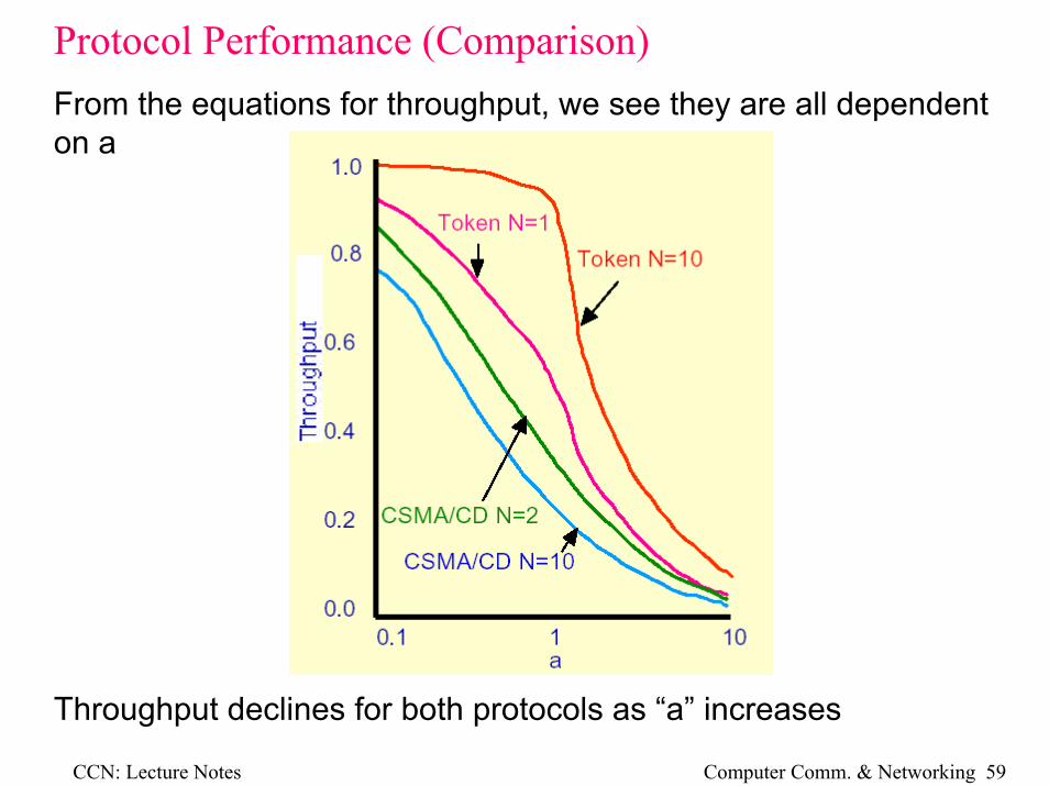
Protocol Performance (Comparison) From the equations for throughput, we see they are all dependenton a
Throughput declines for both protocols as “a” increases
CCN: Lecture Notes Computer Comm. & Networking 60
Protocol Performance (Comparison)
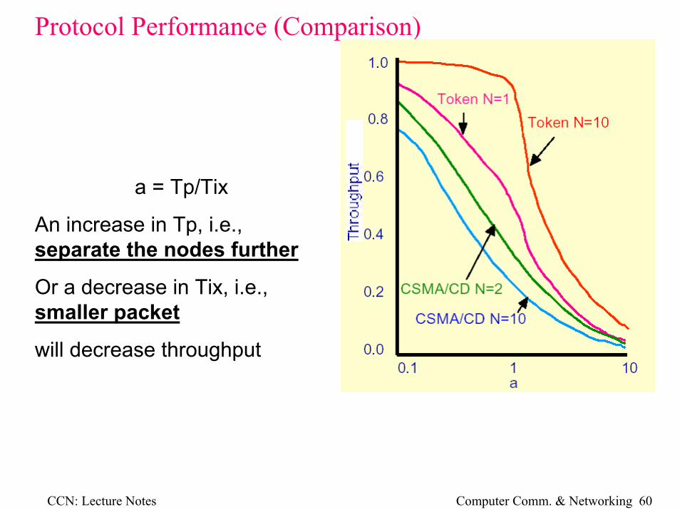
a = Tp/Tix
An increase in Tp, i.e., separate the nodes further
Or a decrease in Tix, i.e., smaller packet
will decrease throughput
CCN: Lecture Notes Computer Comm. & Networking 61
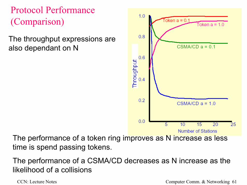
The performance of a token ring improves as N increase as less time is spend passing tokens.
The performance of a CSMA/CD decreases as N increase as the likelihood of a collisions
Protocol Performance (Comparison)
The throughput expressions are also dependant on N
CCN: Lecture Notes Computer Comm. & Networking 62
Protocol Performance (Comparison)
The Asymptotes for each curve for large N are
><
=∞→ 11
11lim a
a
aUringToken
N
aUCDCSMA
N 44.311lim/
+=
∞→
Examination of a real network is much more complex and requires the use of a simulation system
Let us examine the 3 protocols for variations in packet size, active stations and data rate to ascertain the effective data transfer rate.
In all cases, the network is being fully occupied by the stated number of stations.
CCN: Lecture Notes Computer Comm. & Networking 63
Protocol Performance (Comparison)
2000 bits/packet – 100 active stations out of 100 station total
• Ideal is straight line
• As data rate increases, Tix decreases, thus ‘a’ increase (a = Tp/Tix)
• CSMA/CD is very dependent on ‘a’
• Token control is not as dependant on ‘a’
CCN: Lecture Notes Computer Comm. & Networking 64
• As packet size decreases, Tix decreases, thus ‘a’ increase (a = Tp/Tix)• Overall efficiency is reduced when max pocket size is small• CSMA/CD is very dependant on ‘a’ and is virtually useless for small
packet sizes when a large number of stations are trying to transmit.• Throughput actually decrease when the load gets very high• Token ring is not as dependant on ‘a’, but has much reduced throughput
due to small packets (see equation)
Protocol Performance (Comparison)
500 bits/packet – 100 active stations out of 100 station total
CCN: Lecture Notes Computer Comm. & Networking 65
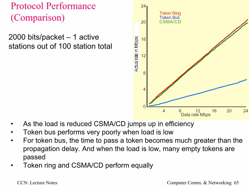
Protocol Performance (Comparison)
2000 bits/packet – 1 active stations out of 100 station total
• As the load is reduced CSMA/CD jumps up in efficiency• Token bus performs very poorly when load is low• For token bus, the time to pass a token becomes much greater than the
propagation delay. And when the load is low, many empty tokens are passed
• Token ring and CSMA/CD perform equally
CCN: Lecture Notes Computer Comm. & Networking 66
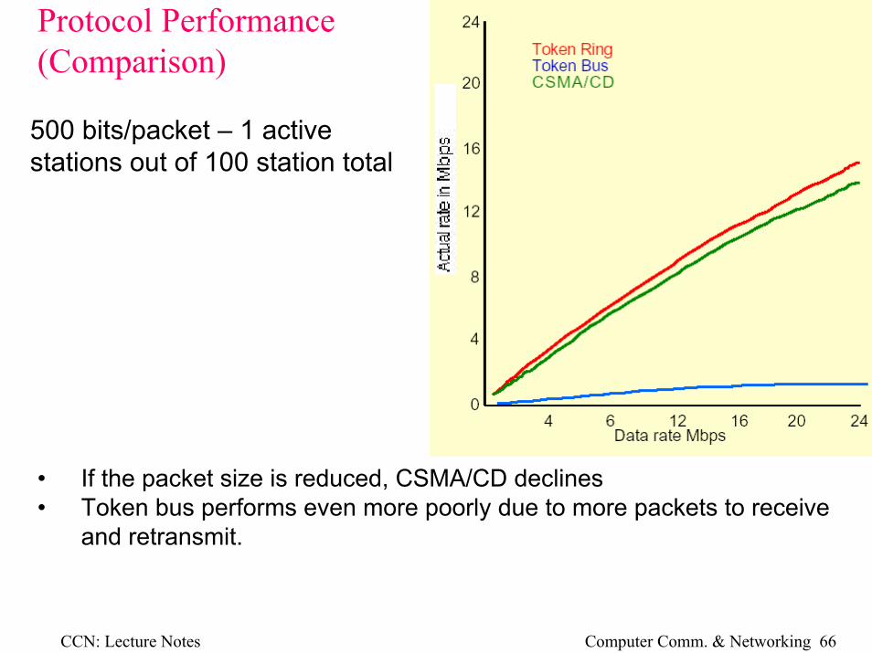
Protocol Performance (Comparison)
500 bits/packet – 1 active stations out of 100 station total
• If the packet size is reduced, CSMA/CD declines• Token bus performs even more poorly due to more packets to receive
and retransmit.
CCN: Lecture Notes Computer Comm. & Networking 67
Protocol Performance (Summary) • If frames get small, more must be sent and the probability of
collision is greater, thus CSMA/CD throughput falls.
• Small frames also increase the overheads.
• CSMA/CD is good for low to medium loads
— Most LAN’s operate predominantly with low to medium loads
• CSMA/CD is not suited to very high bit rates
— Problems with ‘a’
— If Tix<2Tp, initial station may not detect collision
• Token ring is good for high load
• CSMA/CD is easily implemented
• Token ring is harder to cable and prone to disruption.
CCN: Lecture Notes Computer Comm. & Networking 68
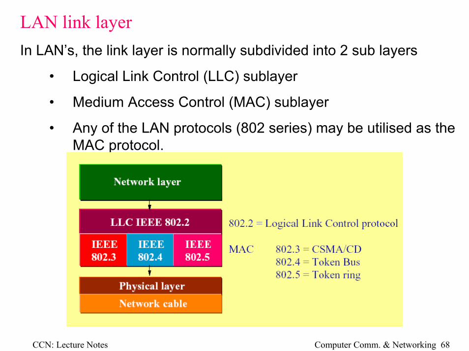
LAN link layerIn LAN’s, the link layer is normally subdivided into 2 sub layers
• Logical Link Control (LLC) sublayer
• Medium Access Control (MAC) sublayer
• Any of the LAN protocols (802 series) may be utilised as the MAC protocol.
CCN: Lecture Notes Computer Comm. & Networking 69
Fiber Distributed Data Interface (FDDI)FDDI employs
• Ring topology
• Fiber-optic cabling as its physical medium
• 100Mbps
CCN: Lecture Notes Computer Comm. & Networking 70
FDDI--architecture
• FDDI’s counter rotating ring architecture.
• The primary ring is active in normal operation.
• The secondary ring provides redundancy.
• All devices on the ring are dualattachment stations (Class A nodes) or dual-attachment hubs.
CCN: Lecture Notes Computer Comm. & Networking 71
FDDI– self healFDDI has the ability to “self-heal” if the ring topology is cut in a single spot. This is called autowrapping.
In the event of a fiber cut or an inoperative node,
• FDDI automatically wrap the ring at the point of failure.
• interconnecting the primary and secondary rings into a single functional ring.
CCN: Lecture Notes Computer Comm. & Networking 72
FDDI– data
In FDDI, the data around the ring is not phase locked. Each station receives the bit stream and extracts the clock to decodethe data then transmits the data using its own clock.
Clocking information is included in the bit stream with a 4B/5B code and a NRZI line code.
CCN: Lecture Notes Computer Comm. & Networking 73
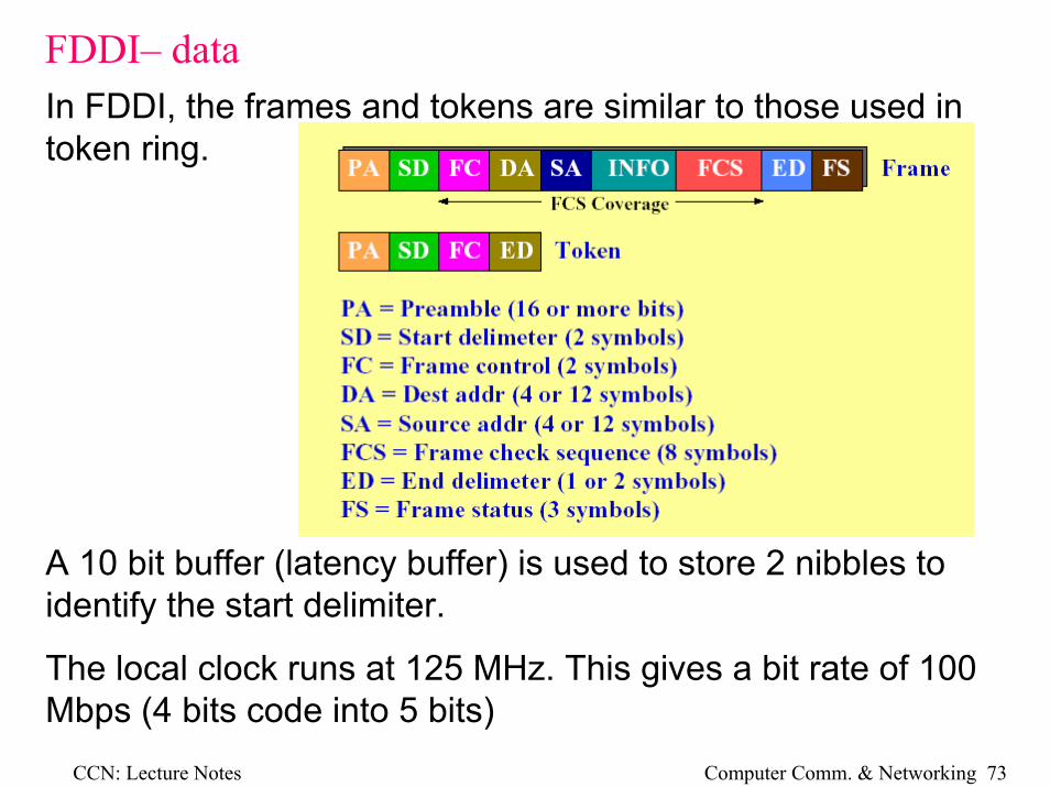
FDDI– dataIn FDDI, the frames and tokens are similar to those used in token ring.
A 10 bit buffer (latency buffer) is used to store 2 nibbles to identify the start delimiter.
The local clock runs at 125 MHz. This gives a bit rate of 100 Mbps (4 bits code into 5 bits)
CCN: Lecture Notes Computer Comm. & Networking 74
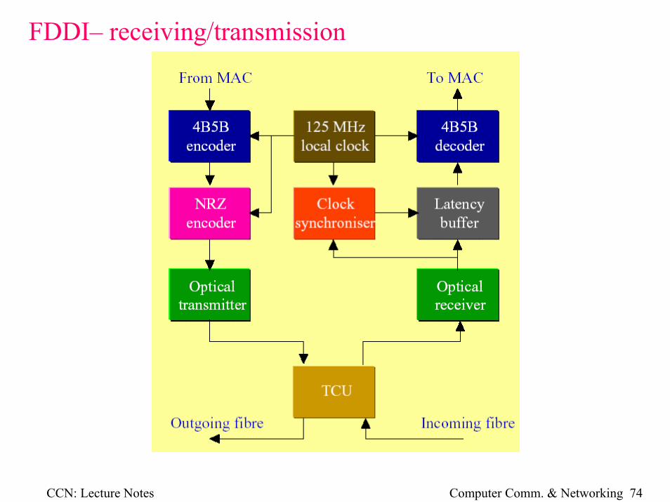
FDDI– receiving/transmission
CCN: Lecture Notes Computer Comm. & Networking 75
FDDIFDDI uses early token release. The latency of an FDDI ring is large as each station has a 10 bit buffer and there could be 1000 stations.
Priorities are handled similarly to token bus. The Token Rotation Time (TRT) increases as the ring becomes more heavily loaded. Each station measures the TRT and will only transmit a frame when theTRT becomes lower than the TRT target (TRTT) for that frame. High priority frames have high TRTT’s.
The system has the ability to send synchronous data, i.e., real time data like digitized speech. These frames have maximum priority.
CCN: Lecture Notes Computer Comm. & Networking 76
Bridges, Repeaters and Switches--RepeaterWe often wish to join LAN’s together, a repeater will simply relay data from one segment to another. It is simply a dumb physical layer device.
CCN: Lecture Notes Computer Comm. & Networking 77
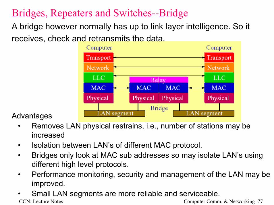
Bridges, Repeaters and Switches--BridgeA bridge however normally has up to link layer intelligence. So it receives, check and retransmits the data.
Advantages• Removes LAN physical restrains, i.e., number of stations may be
increased• Isolation between LAN’s of different MAC protocol.• Bridges only look at MAC sub addresses so may isolate LAN’s using
different high level protocols.• Performance monitoring, security and management of the LAN may be
improved.• Small LAN segments are more reliable and serviceable.
CCN: Lecture Notes Computer Comm. & Networking 78
Bridges, Repeaters and Switches--Bridge
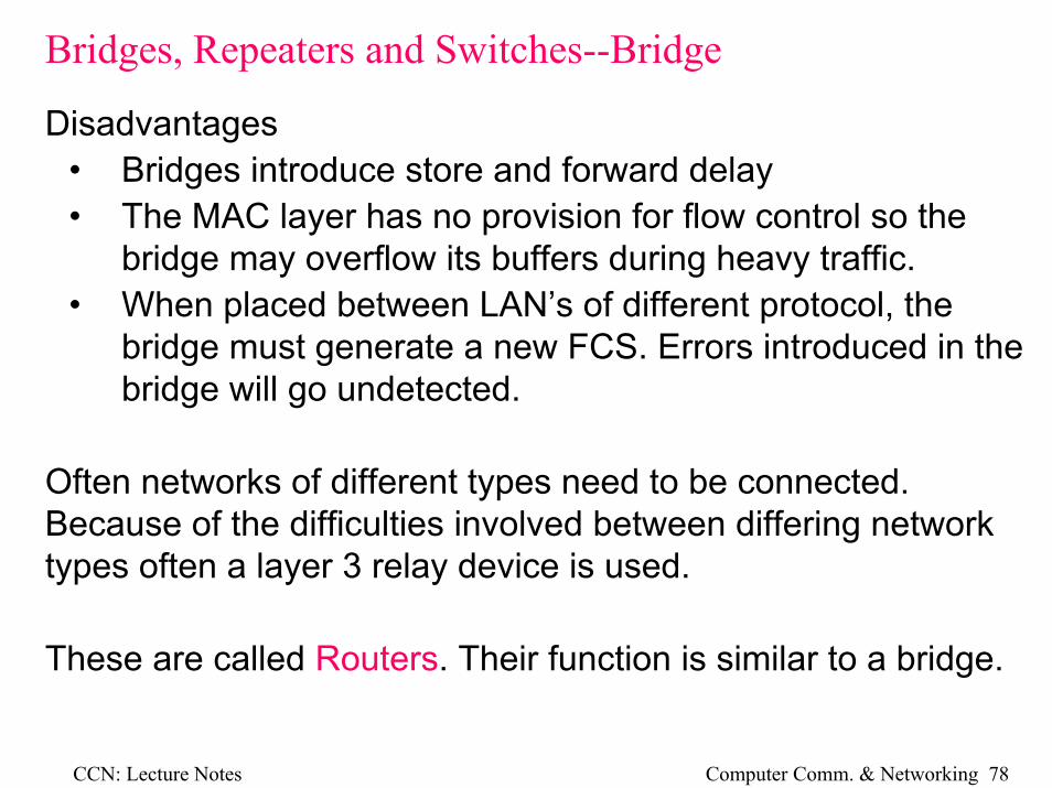
Disadvantages• Bridges introduce store and forward delay• The MAC layer has no provision for flow control so the
bridge may overflow its buffers during heavy traffic.• When placed between LAN’s of different protocol, the
bridge must generate a new FCS. Errors introduced in the bridge will go undetected.
Often networks of different types need to be connected. Because of the difficulties involved between differing network types often a layer 3 relay device is used.
These are called Routers. Their function is similar to a bridge.
CCN: Lecture Notes Computer Comm. & Networking 79
Bridges, Repeaters and Switches—Switches
Switches are now more commonly used for lower level route control and network segmentation. Ethernet switches are a layer 2 device. They are different to bridges in that they can implement multiple switched connections between ports on the switch.
Switches may be :Store and forward switches work like a bridge where they store the packet before retransmission. They therefore have high latency. (1 ms or more)Cut through switches divert the packet out the appropriate port as soon as they read the MAC address. Latency for these switches isvery low (20µs)Hybrid switches can do both and will change from one method to the other as traffic demands.
CCN: Lecture Notes Computer Comm. & Networking 80
Switches – Transparent routing
A routing device such as a bridge is connected to a LAN via a port. Each port contains the required hardware to suit the MAC protocol.
CCN: Lecture Notes Computer Comm. & Networking 81
Switches – Transparent routing
All frames received on a port are stored in memory. The frame must then be transmitted on the appropriate port, according to the destination address of the frame, when that port is free.
Every bridge must know which port to send a frame out on to access each station. This information is called the forwarding database (FDB) and is usually learnt by the bridge. A bridge will discard a frame if it should transmit it on the port it received it on.
CCN: Lecture Notes Computer Comm. & Networking 82
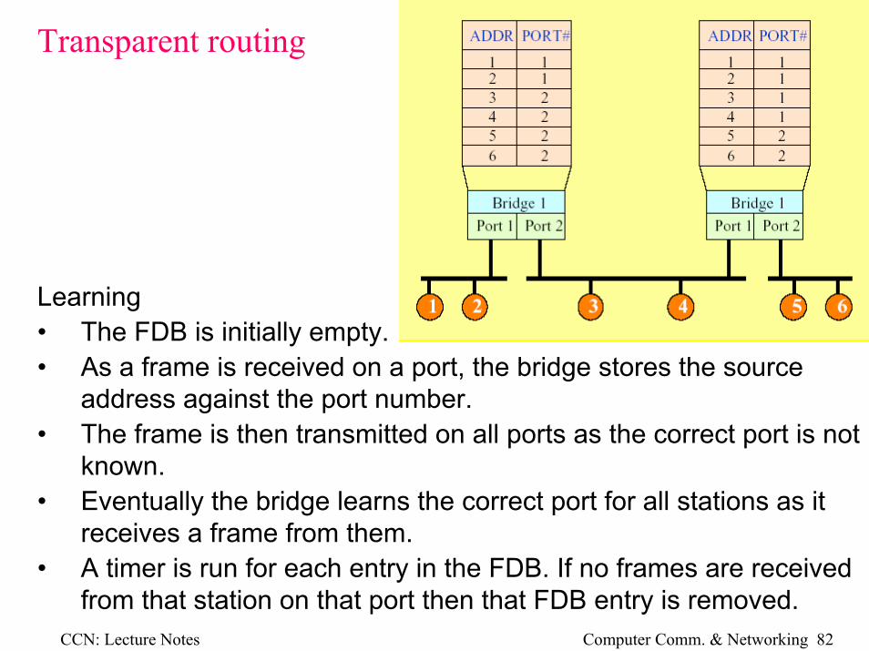
Transparent routing
Learning• The FDB is initially empty.• As a frame is received on a port, the bridge stores the source
address against the port number.• The frame is then transmitted on all ports as the correct port is not
known.• Eventually the bridge learns the correct port for all stations as it
receives a frame from them.• A timer is run for each entry in the FDB. If no frames are received
from that station on that port then that FDB entry is removed.
CCN: Lecture Notes Computer Comm. & Networking 83
Transparent routing
A spanning tree algorithm is a common transparent routing solution
• The network dynamically allocates costs to all paths through thenetwork.
• A bridge is assigned the root bridge to another LAN if it has the lowest cost.
• For each packet to be sent, the path of lowest cost to the routebridge is chosen
• This system is transparent to nodes as all routing is done by the bridges
CCN: Lecture Notes Computer Comm. & Networking 84
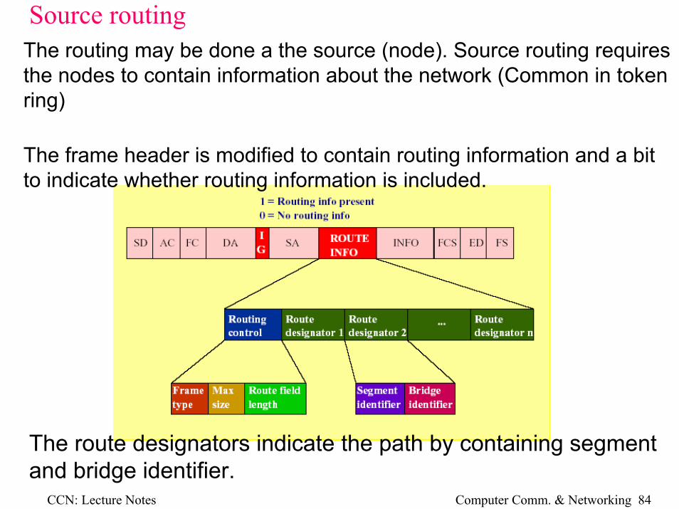
Source routingThe routing may be done a the source (node). Source routing requires the nodes to contain information about the network (Common in token ring)
The frame header is modified to contain routing information and a bit to indicate whether routing information is included.
The route designators indicate the path by containing segment and bridge identifier.