MODULE 5 Storage Options for CO 2 : Types of Geological Storage Projects (W. D. Gunter) LEARNING OBJECTIVES Geological storage is one option for storing CO 2 from the atmosphere as a means of combating climate change. These sinks are most suitable for utilization by large CO 2 emission point sources with relatively pure CO 2 waste streams. Generally, with the exception of enhanced oil recovery, the retention times for carbon dioxide within these sinks are on the order of 10 5 to 10 6 years and longer. By the end of this Module you will: • Understand the concept of geological carbon storage; • Know the different geological CO 2 storage options, including the difference between value added and non-value added storage options; • Be familiar with current practices and special issues related to each of these storage options; • Know how CO 2 and gas have been stored naturally in various reservoirs; • Appreciate the maturity of the technology and areas of development still required; • Understand what is needed to speed up commercialization of CO 2 storage in geological media. Asia-Pacific Economic Cooperation 5-1 Building Capacity for CO 2 Capture and Storage in the APEC Region
Transcript
StoraTypes of Ge
LEA
RN
ING
OB
JEC
TIVE
S
Geological storage is one option
climate change. These sinks are
with relatively pure CO2 waste str
retention times for carbon dioxide
By the end of this Module you wil
• Understand the concept of
• Know the different geolog
added and non-value adde
• Be familiar with current pra
• Know how CO2 and gas ha
• Appreciate the maturity of t
• Understand what is neede
media.
Asia-Pacific Economic Cooperation Buildin
MODULE 5
ge Options for CO2: ological Storage Projects
(W. D. Gunter)
for storing CO2 from the atmosphere as a means of combating
most suitable for utilization by large CO2 emission point sources
eams. Generally, with the exception of enhanced oil recovery, the
within these sinks are on the order of 105 to 10
6 years and longer.
l:
geological carbon storage;
ical CO2 storage options, including the difference between value
d storage options;
ctices and special issues related to each of these storage options;
ve been stored naturally in various reservoirs;
he technology and areas of development still required;
d to speed up commercialization of CO2 storage in geological
5-1 g Capacity for CO2 Capture and Storage in the APEC Region
GEOLOGICAL STORAGE
Geosphere sinks are naturally occurring reservoirs that historically, on a geologic time basis, have been
sinks for carbon. Humans have extracted carbon from these sinks in the form of oil, gas and coal, to use
for energy. These same reservoirs, including deep aquifers, can be used to store carbon dioxide,
reducing the amount of CO2 available in the global carbon balance.
CO2 STORAGE OPTIONS IN GEOLOGICAL MEDIA
Storage options for CO2 in geological media can be divided into two primary categories (see Figure 5.1),
and a secondary category:
Primary categories:
• Value-added options - reservoirs that typically began as a
commercially developed site to enhance recovery of fossil fuel fluids.
However, they have a secondary benefit of providing a storage site
for CO2 (through the recovery process); and
Value-added and non-value added options for CO2 storage are the two primary means of storage of CO2 in geological media. The advantages of value-added options such as EOR and EGR are that they provide suitable, secure reservoirs for carbon storage; off-set the cost of capture, transport and storage; and use technology and infrastructure which can be easily adapted to CO2 injection.
• Non-value added options – reservoirs that would only be
developed to contain CO2 emissions. Thus these are only
economically viable if CO2 emission reduction regulations were
imposed or a revenue stream could be generated from sales of CO2
credits. With the entry into force of the Kyoto Protocol on February
16, 2005, non-value added options are currently attractive. The
Kyoto Protocol is an international agreement that commits nations to
reduce their greenhouse gas emissions by a certain percentage
below 1990 levels. For more information, see Module 11: The Clean
Development Mechanism.
Asia-Pacific Economic Cooperation 5-2 Building Capacity for CO2 Capture and Storage in the APEC Region
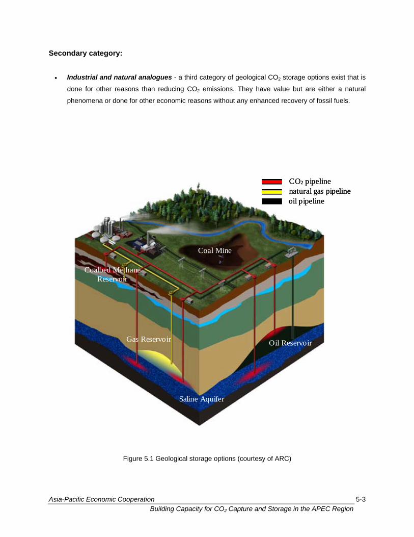
Secondary category:
• Industrial and natural analogues - a third category of geological CO2 storage options exist that is
done for other reasons than reducing CO2 emissions. They have value but are either a natural
phenomena or done for other economic reasons without any enhanced recovery of fossil fuels.
Coalbed MethaneReservoir
Gas Reservoir
Saline Aquifer
Oil Reservoir
Coal Mine
CO2 pipelinenatural gas pipelineoil pipeline
Coalbed MethaneReservoir
Gas Reservoir
Saline Aquifer
Oil Reservoir
Coal Mine
CO2 pipelinenatural gas pipelineoil pipeline
CO2 pipelinenatural gas pipelineoil pipeline
Figure 5.1 Geological storage options (courtesy of ARC)
Asia-Pacific Economic Cooperation 5-3 Building Capacity for CO2 Capture and Storage in the APEC Region
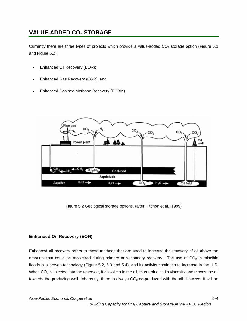
VALUE-ADDED CO2 STORAGE
Currently there are three types of projects which provide a value-added CO2 storage option (Figure 5.1
and Figure 5.2):
• Enhanced Oil Recovery (EOR);
• Enhanced Gas Recovery (EGR); and
• Enhanced Coalbed Methane Recovery (ECBM).
Figure 5.2 Geological storage options. (after Hitchon et al., 1999)
Enhanced Oil Recovery (EOR) Enhanced oil recovery refers to those methods that are used to increase the recovery of oil above the
amounts that could be recovered during primary or secondary recovery. The use of CO2 in miscible
floods is a proven technology (Figure 5.2, 5.3 and 5.4), and its activity continues to increase in the U.S.
When CO2 is injected into the reservoir, it dissolves in the oil, thus reducing its viscosity and moves the oil
towards the producing well. Inherently, there is always CO2 co-produced with the oil. However it will be
Asia-Pacific Economic Cooperation 5-4 Building Capacity for CO2 Capture and Storage in the APEC Region
captured and reinjected into the reservoir. For immiscible floods, significantly more CO2 may be left in the
reservoir.
EOR is likely the first and most economic line of carbon dioxide mitigation processes, though other methods will become more viable as technology develops. There is a global potential of 20 – 65 Gt C for EOR. It permits 10-12% of additional oil reserves to be tapped. However, the return on investment for EOR is highly dependent on the price of oil, the price of CO2 and individual reservoir characteristics.
In the case of EOR, the oil-carbon dioxide mixture is separated at the
surface and the oil is used as fuel in the normal way. While this produces
more carbon dioxide, the solution to that problem is clear. The carbon
dioxide that is returned to the surface could be re-used for more oil
recovery or disposed of in deep aquifers. It should be noted that EOR is
likely the first and most economic line of carbon dioxide mitigation
processes, though other methods will become more viable as technology
develops. The recycling of gases in EOR and EGR is possible because
there is a close association of the fossil fuel resources of sedimentary
basins and the greenhouse gas emitting industry that is based on those
fuels.
Figure 5.3 Schematic of a miscible CO2 flood for enhanced oil recovery, EOR (courtesy of ARC)
Asia-Pacific Economic Cooperation 5-5 Building Capacity for CO2 Capture and Storage in the APEC Region
Globally, the EOR–CO2 sink has an estimated capacity of 20 to 65 Gt C. Use of this sink is restricted to
economies that have oil reservoirs suitable for EOR–CO2 recovery techniques (refer to Module 13: The
Potential of CO2 Capture and Storage in the APEC Region). Use of CO2 for EOR is capable of storing a
large quantity of CO2, resulting in a net reduction in CO2, but the overall return on investment (either
positive or negative) is highly dependent on factors such as the price of oil, price of CO2 and individual
reservoir characteristics.
In Canada, availability and cost have
favoured the use of ethane over carbon
dioxide as the miscible solvent of choice.
Recently, however EnCana Ltd. of Calgary,
Alberta are buying carbon dioxide from the
Great Plains coal-gasification plant at Beulah,
North Dakota, USA. The plant produces
pipeline quality synthetic natural gas, and
other products, by gasification of lignite from
local mines. The carbon dioxide (up to
13,000 tonnes/day) is piped 330 km to be
used for EOR in the Weyburn Field,
Saskatchewan, Figure 5.4 (See the Weyburn
CO2 Monitoring and Storage Project Case
Study in the Case Study section of this
training guide for more information about this
project).
This will be the largest EOR operation in Canada and will extend the life of the field as much as 25 years
through a 20% increase in cumulative production by the year 2008. This association of available waste
carbon dioxide and a distant oil field using carbon dioxide for enhanced oil recovery is economically
viable after expenditures of more than a billion dollars—surely one of the best illustrations of the possible
synergies of “waste and want” in sedimentary basins.
Figure 5.4 EOR operations in Weyburn, Saskatchewan, Canada (courtesy of EnCana)
Asia-Pacific Economic Cooperation 5-6 Building Capacity for CO2 Capture and Storage in the APEC Region
If the carbon dioxide is injected into the gas cap of an oil reservoir there is additional pressure drive
provided for oil recovery. In the oil sand deposits of Alberta, the production rate and recovery of bitumen
during Steam Assisted Gravity Drainage (SAGD) can be affected by the production of gas from
associated reservoirs. It has been proposed to re-pressurize the gas reservoirs with carbon dioxide to
enhance the economic production of bitumen.
he advantages of using carbon dioxide for EOR operations and injecting it into depleted oil and gas
- The main attraction to
nd gas recovery operations
m a reservoir. In general,
be tapped through primary
rocesses. The use of CO2
ximately 10 to 12% of the
sed opportunity to
ources, EOR provides an
c ase production from
stream
rbon dioxide;
Availability of secure storage – there is an opportunistic
association between hydrocarbon production and the presence of
e adapted for carbon
dioxide injection; this ranges from knowledge of exploration for and
production from reservoirs, through all aspects of gas separation,
the handling of high pressure fluids and pipelining, to ensuring safe
operations and appropriate environmental studies.
T
reservoirs are:
• Opportunity to increase productionusing CO2 storage techniques for oil a
is the higher recovery of the fuel fro
approximately 40% of oil reserves can
(~25 to 30%) and secondary (~10%) p
can aid in the recovery of up to appro
remaining fuel;
• Cost effectiveness – following from increa
produce additional hydrocarbon res
economically attractive way to in
operational oil reservoirs. This revenue
of capture, transport and injection of ca
•
The advantages of EOR are: • It provides an
opportunity to increase existing hydrocarbon production;
• It is a cost effective re
can offset the cost means of financing a CO2 storage project;
• Hydrocarbon reservoirs are often ideal storage sites for CO2;
• Supporting infrastructure often reservoirs suitable for CO2 injection. The geological processes that
allowed the accumulation of hydrocarbons also permit the secure
storing of injected carbon dioxide;
• Availability of supporting infrastructure - the technology and
infrastructure for oil and gas production can b
exists, which also decreases the cot of the CO2 storage project.
Asia-Pacific Economic Cooperation 5-7 Building Capacity for CO2 Capture and Storage in the APEC Region
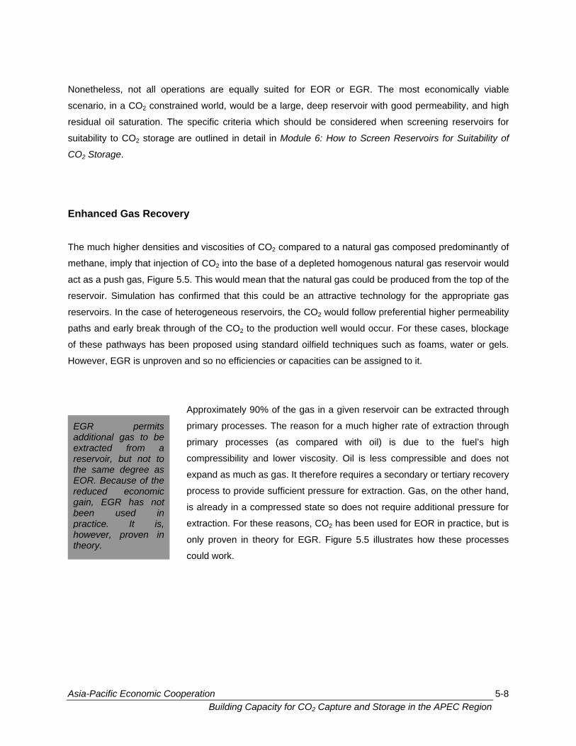
Nonetheless, not all operations are equally suited for EOR or EGR. The most economically viable
s Recovery
he much higher densities and viscosities of CO2 compared to a natural gas composed predominantly of
met n tural gas reservoir would
act as a produced from the top of the
reservoi logy for the appropriate gas
reservoi eferential higher permeability
paths a r. For
of these ch a ater or gels.
Howeve en and so no efficiencies or capacities can be assigned to
ir can through
r rat
is due
ity. Oil is less comp es not
expand as much as gas. It therefore requires a seconda
on. Ga
quire ssure for
ed for E
trates h
scenario, in a CO2 constrained world, would be a large, deep reservoir with good permeability, and high
residual oil saturation. The specific criteria which should be considered when screening reservoirs for
suitability to CO2 storage are outlined in detail in Module 6: How to Screen Reservoirs for Suitability of
CO2 Storage.
Enhanced Ga T
ha e, imply that injection of CO2 into the base of a depleted homogenous na
push gas, Figure 5.5. This would mean that the natural gas could be
r. Simulation has confirmed that this could be an attractive techno
rs. In the case of heterogeneous reservoirs, the CO2 would follow pr
nd early break through of the CO2 to the production well would occu
pathways has been proposed using standard oilfield techniques su
r, EGR is unprov
these cases, blockage
s foams, w
it.
be extractedApproximately 90% of the gas in a given reservo
primary processes. The reason for a much highe
primary processes (as compared with oil)
compressibility and lower viscos
EGR e of extraction through
to the fuel’s high
ressible and do
ry or tertiary recovery
s, on the other hand,
permits additional gas to be extracted from a reservoir, but not to the same degree as EOR. Because of the reduced economic gain, EGR has not been used in
process to provide sufficient pressure for extracti
is already in a compressed state so does not re
extraction. For these reasons, CO
additional pre
OR in practice, but is
ow these processes2 has been us
only proven in theory for EGR. Figure 5.5 illus
could work.
practice. It is, however, proven in theory.
Asia-Pacific Economic Cooperation 5-8 Building Capacity for CO2 Capture and Storage in the APEC Region
Figure 5.5 Schematic of enhanced gas recovery using CO2to displace the natural gas, EGR (courtesy of ARC)
Enhanced Coalbed Methane Recovery
Asia-Pacific Economic Cooperation 5-9 Building Capacity for CO2 Capture and Storage in the APEC Region
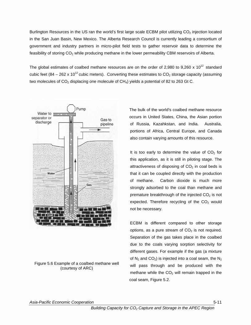
The use of coal beds as a reservoir rock for storing CO2 is novel. Coal
beds contain significant amounts of methane gas - called coalbed
methane or CBM - adsorbed in the coal. Current commercial
technologies first dewater the coal in order to release the adsorbed gas,
Figure 5.6. On the other hand, by injecting CO2 into the coal beds, the
CO2 is adsorbed in the coal pore matrix, releasing the methane.
Experimental results show that two to ten molecules of CO2 can be
adsorbed in the coal matrix for every molecule of methane it displaces.
The use of CO2 for CBM recovery would have the same effect as
enhanced oil recovery and is classified as an enhanced coalbed
methane recovery (ECBM).
By injecting CO2 into the coal beds, the CO2 is adsorbed in the coal pore matrix, releasing the methane. The methane can be sold as a revenue source. There is a global storage capacity of between 82 to 263 Gt C in coal beds.
Asia-Pacific Economic Cooperation 5-10 Building Capacity for CO2 Capture and Storage in the APEC Region
Burlington Resources in the US ran the world’s first large scale ECBM pilot utilizing CO2 injection located
rrently leading a consortium of
o e
BM
,980 rd
2 st g
82 to
The bulk of the world’s coalbed methane resource
occurs in United States, China, the Asian portion
of Russia, Kazahkstan, and India. Australia,
portions of Africa, Central Europe, and Canada
also contain varying amounts of this resource.
It is too early to determine the value of CO2 for
this application, as it is still in piloting stage. The
attractiveness of disposing of CO2 in coal beds is
that it can be coupled directly with the production
of methane. Carbon dioxide is much more
strongly adsorbed to the coal than methane and
premature breakthrough of the injected CO2 is not
expected. Therefore recycling of the CO2 would
not be necessary.
ECBM is different compared to other storage
options, as a pure stream of CO2 is not required.
Separation of the gas takes place in the coalbed
due to the coals varying sorption selectivity for
different gases. For example if the gas (a mixture
of N2 and CO2) is injected into a coal seam, the N2
will pass through and be produced with the
methane while the CO2 will remain trapped in the
coal seam, Figure 5.2.
Figure 5.6 Example of a coalbed methane well (courtesy of ARC)
in the San Juan Basin, New Mexico. The Alberta Research Council is cu
government and industry partners in micro-pilot field tests to gather reserv
feasibility of storing CO
ir data to determine th
reservoirs of Alberta.
to 9,260 x 10
2 while producing methane in the lower permeability C
The global estimates of coalbed methane resources are on the order of 2
cubic feet (84 – 262 x 10
12 standa
orage capacity (assumin
263 Gt C.
12 cubic meters). Converting these estimates to CO
two molecules of CO2 displacing one molecule of CH4) yields a potential of
Asia-Pacific Economic Cooperation 5-11 Building Capacity for CO2 Capture and Storage in the APEC Region
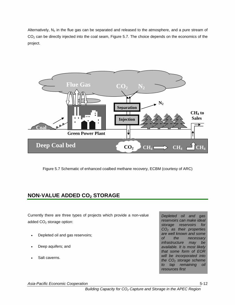
Alternatively, N2 in the flue gas can be separated and released to the atmosphere, and a pure stream of
CO2 can be directly injected into the coal seam, Figure 5.7. The choice depends on the economics of the
project.
Figure 5.7 Schematic of enhanced coalbed me NON-VALUE ADDED CO2 STORAGE
thane recovery, ECBM (courtesy of ARC)
Currently there are three types of projects which prov
added CO2 storage option:
• Depleted oil and gas reservoirs;
• Salt caverns.
ide a non-value
• Deep aquifers; and
CO2Deep Coal bed CH4 CH4CH4
CH4 to Sales
N2
Coal
Flue Gas CO2 N2
Injection
Green Power Plant
Separation
Asia-Pacific Economic Cooperation Building Capacity for CO2 Capture and Stora
Depleted oil and gas reservoirs can make ideal storage reservoirs for CO2 as their properties are well known and some of the necessary infrastructure may be available. It is most likely that some form of EOR will be incorporated into the CO2 storage scheme to tap remaining oil resources first
5-12 ge in the APEC Region
Depleted Oil & Gas Reservoirs
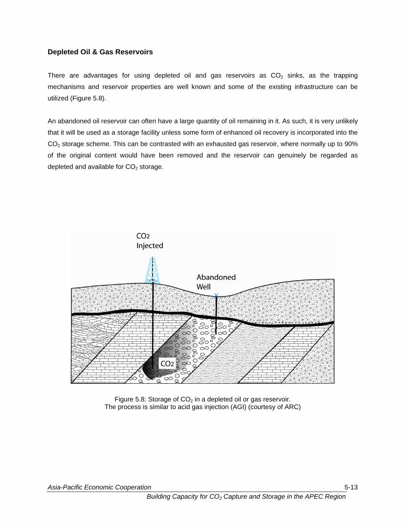
There are advantages for using depleted oil and gas reservoirs as CO2 sinks, as the trapping
echanisms and reservoir properties are well known and some of the existing infrastructure can be
tilized (Figure 5.8).
n abandoned oil reservoir can often have a large quantity of oil remaining in it. As such, it is very unlikely
that it will be used as a storage facility unless some form of enhanced oil recovery is incorporated into the
CO2 storage scheme. trasted w a usted rvoir, where normally up to 90%
of the original content would have been re ve he r oir can genuinely be regarded as
depleted and available for CO2 storage.
m
u
A
This can be con ith
mo
n exha
d and t
gas rese
eserv
rvoir. of ARC)
e of CO2 in a depleted oil or gas rese
ar to acid gas injection (AGI) (courtesy
Figure 5.8: StoragThe process is simil
Asia-Pacific Economic Cooperation 5-13 Building Capacity for CO2 Capture and Storage in the APEC Region
and gas is 150 Gt CO2 (40 Gt C) and 520 Gt CO2 (140 Gt C) respectively. This is
omparable to the estimates in the Second Assessment Report of the Intergovernmental Panel on
There is not a
case of EOR,
As oil prices i
depletion of th
emitting CO2 b
atmosphere, E
sliding scale b
processes will
reservoir reach
The total global storage potential of all oil and gas fields in the world is estimated to be 670 Gt of CO2
(180 Gt C) assuming the entire volume can be displaced with CO2 at some time in the future. The
distribution between oil
c
Climate Change (IPCC). An estimate for the cost of disposing CO2 into an abandoned onshore gas
reservoir was about 1.93 ECU/t CO2 or $ US 2.22/t CO2 (about $ US 8/t C). The reservoir used for the
analysis was under-pressured, at a depth of 2,500 meters.
Asia-Pacific Ec
The total global storage potential of oil and gas fields is approximately 670 Gt of CO2 (180 Gt C). The distribution between oil and gas is 150 Gt CO2 (40 Gt C) and 520 Gt CO2 (140 Gt C) respectively. The primary difference between EOR/EGR and Depleted Oil and Gas Field CO2 storage is based on the cost of producing oil versus the value of the oil. As oil prices increase, the amount of oil recovered by EOR processes will increase as well because it will be economically viable. Similarly, as restrictions on CO2 begin to occur, industry will place a value on minimizing CO2 emissions from their operations.
sharp division between the EOR/EGR and Depleted Oil and Gas Fields categories. In the
for example, it is strictly based on the cost of producing the oil versus the value of the oil.
ncrease, the amount of oil recovered by EOR processes will go up and result in more
e reservoir before it is abandoned and available for storage only. Similarly as the value of
ecomes an economical burden, and industry is paid to prevent the CO2 from entering the
OR pro Thus there exists a
ase ines when EOR
be halted (i.e. production ceases) and only storage continues (i.e. injection of CO2) until the
es its maximum pressure or volume for safe storage.
jects will extend the depletion of oil reservoirs even further.
d on the economics of oil recovery and CO2 storage that determ
onomic Cooperation 5-14 Building Capacity for CO2 Capture and Storage in the APEC Region
For the future, better CO2 capture techniques will be needed for the CO2 purification and pressurization
steps in order to develop the best approach. This is because impurities in the CO2 can significantly
quifers in
sedimentary basins has been shown to be a technically feasible
torage option. Carbon dioxide is an ideal candidate for aquifer storage
because of its high density and high solubility in water at the relatively
igh pressures which exist in deeper aquifers, Figure 5.2 and 5.9. Deep
quifers are the
the world.
Deep aquifers
f CO2 trapped
ssure a
seals. At reser
nd pressure of the CO2 would be above the supercritcal condition,
which is desirable from a storage perspective.
Refer to Module 6 for the conditions that must be satisfied for injection
2. Global estimates of the capacity of this storage option vary
reduce the amount which can be stored, enhance corrosion and increase capital costs. Legal questions
also need to be resolved regarding ownership of the residual hydrocarbons.
Deep Aquifers
Carbon dioxide storage into low to high permeability deep a
s
h
largest potential for CO2 storage in landlocked areas of a
Storage of CO2 in low permeability, deep aquifers in sedimentary basins is technically feasible, but is only in the piloting stage.
contain high salinity water and could host large amounts
by the formation pressure. The determining factors are
nd temperature in the reservoir and the integrity of the
voir depths of 800 meters and greater, the temperature
o
the pre
a
of CO
greatly due to different assumptions with respect to aquifer volumes,
percent of the reservoir filled, density of CO2 under reservoir
conditions, and the volume suitable for storage. It ranges from 87 Gt C
to 14,000 Gt C if structural traps are not required for secure storage.
Asia-Pacific Economic Cooperation 5-15 Building Capacity for CO2 Capture and Storage in the APEC Region
Current Demonstration Projects Currently, there are three projects which could serve to illustrate the feasibility of aquifer storage.
a is a large scale project in the
n tonnes of CO2
ndix
r operation). Preliminary economic
assessment indicated that significant costs will be incurred due
mainly to carbon dioxide capture, purification and compression, and
secondarily due to the field facilities required. Despite these
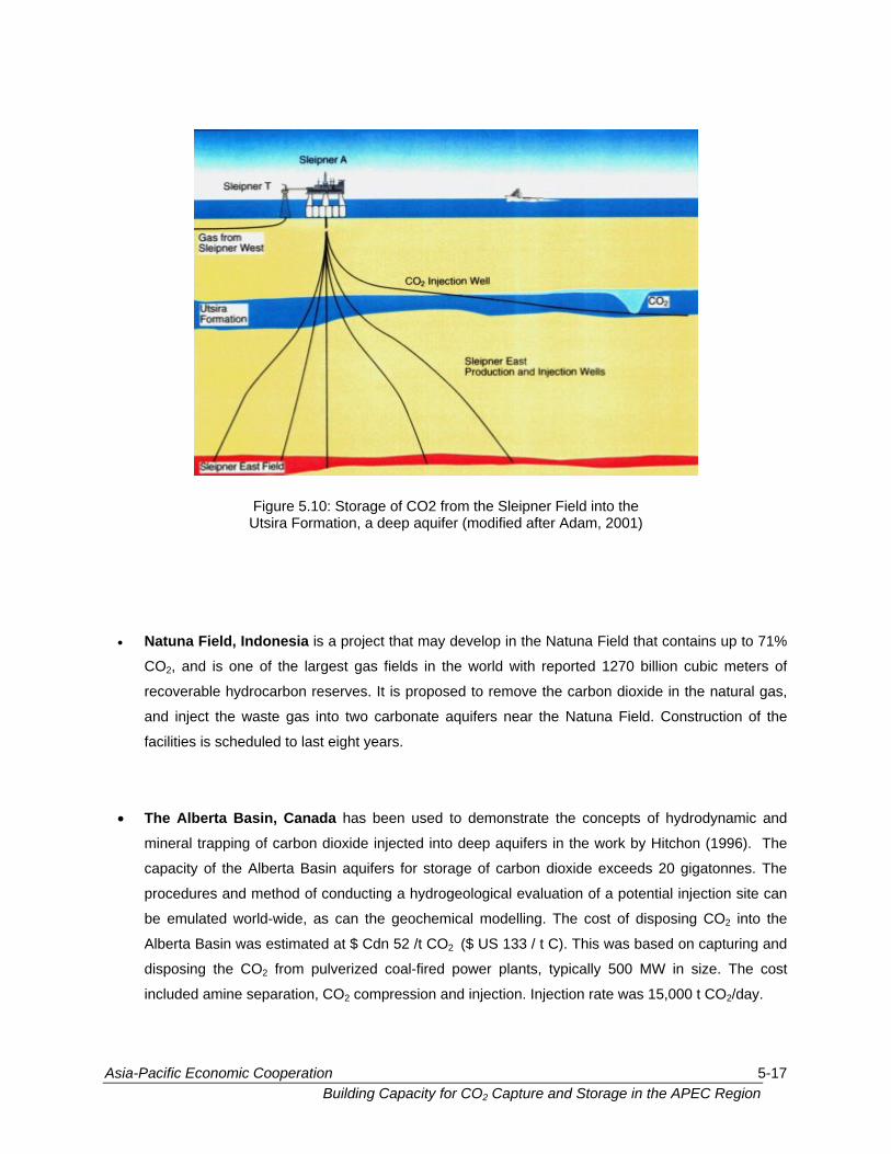
expenses, a recent report on the Sleipner Vest Field in the North Sea
indicates that the 9.5% carbon dioxide will be reduced to 2.5% in the
sales gas, with about 1 million tonnes per year of the waste carbon
dioxide being injected into sandstones of the 200-metre thick
Tertiary Utsira Formation about 1000 metres below the sea bed.
Figure 5.9: Storage of CO2 in deep aquifers (courtesy of ARC)
• Sleipner Vest Field in the North Se
Sleipner Vest Field in the North Sea, where 1 millio
are injected into the aquifer per year (See Figure 5.10 and Appe
A for a Case Study of the Sleipne
There are three projects designed to investigate and illustrate the feasibility of aquifer storage: Sleipner Vest Field (North Sea, Norway); Natuna Field (Indonesia) and the Alberta Basin (Canada).
Asia-Pacific Economic Cooperation 5-16 Building Capacity for CO2 Capture and Storage in the APEC Region
• Natuna Field, Indonesia is a project that may develop in the Natuna Field that contains up to 71%
CO , and is one of the largest gas fields in the world with reported 1270 billion cubic meters of
ral gas,
and inject the waste gas into two carbonate aquifers near the Natuna Field. Construction of the
facilities is scheduled to last eight years.
• Canada arbon dio
rta Basin
hod of con
ide, as can
timated a
from pulv
included amine separation, CO
Figure 5.10: Storage of CO2 from the Sleipner Field into the Utsira Formation, a deep aquifer (modified after Adam, 2001)
2
recoverable hydrocarbon reserves. It is proposed to remove the carbon dioxide in the natu
The Alberta Basin,mineral trapping of c
capacity of the Albe
procedures and met
be emulated world-w
Alberta Basin was es
disposing the CO
has been used to demonstrate the concepts of hydrodynamic and
xide injected into deep aquifers in the work by Hitchon (1996). The
aquifers for storage of carbon dioxide exceeds 20 gigatonnes. The
ducting a hydrogeological evaluation of a potential injection site can
the geochemical modelling. The cost of disposing CO2 into the
t $ Cdn 52 /t CO2 ($ US 133 / t C). This was based on capturing and
erized coal-fired power plants, typically 500 MW in size. The cost 2
2 compression and injection. Injection rate was 15,000 t CO2/day.
Asia-Pacific Economic Cooperation 5-17 Building Capacity for CO2 Capture and Storage in the APEC Region
Although initial injection of carbon dioxide into aquifers in sedimentary basins
will likely be into aquifers containing hydrocarbons (reservoirs), in the long
term it is the deep, non-hydrocarbon producing aquifers that will be the
ultimate sink for carbon dioxide. Not only do these deep aquifers have an
overwhelmingly greater capacity as carbon dioxide sinks, but they occur
throughout all sedimentary basins, at all depths, with a wide variety of
lithologies. Further, it should be possible to locate a suitable aquifer close to
a carbon dioxide source (unlike hydrocarbon reservoirs, of which there is a
paucity in some sedimentary basins).
Salt Caverns
Mining of salt caverns is a mature but expensive
technology. It has been developed for the
underground storage of petroleum, natural gas
and compressed air or for salt mining (see
Figure 5.11). Caverns up to 5x10⁵ m3 in volume
have been developed by solution mining
techniques. Depending on the depth, a single
cavern could hold from 0.2 to 0.5 megatonnes
of CO2. This could store the emissions from a
500 megawatt coalfired power plant for
approximately two months. Salt caverns,
although ideal because of their “zero”
permeability and self-healing properties, are too
expensive to be a major component in
geological storage of CO2 but may have niche
applications where the underlying geologic
media have low permeabilities and porosities.
As salt will flow due to external stresses, the
long-term behaviour of these caverns has not
been properly evaluated for long-term storage.
Figure 5.11: A salt cavern used for storage of natural gas. CO2 storage in salt caverns is similar, but CO2 must remain stored for geological times (modified
after Lambton Industrial Society, 1995)
Initially, CO2 injection is likely to take place in aquifers containing hydrocarbons. Ultimately, deep, non-hydrocarbon producing aquifers will be the ultimate sink for CO2 because of their great abundance.
Asia-Pacific Economic Cooperation 5-18 Building Capacity for CO2 Capture and Storage in the APEC Region
INDUSTRIAL AND NATURAL ANALOGUES
This class of projects provides examples of geological storage of gases for other reasons than reducing
CO2 emissions that is either caused by a natural phenomenon or driven by other economic reasons.
Acid Gas Injection
In the last 15 years, oil and gas producers in the Alberta basin in western
Canada have been faced with a growing challenge to reduce
atmospheric emissions of hydrogen sulphide (H2S), which is produced
from “sour” hydrocarbon pools. Since surface desulphurization is
uneconomic, increasingly more operators are turning to the disposal of
acid gas (H2S and CO2 with minor traces of hydrocarbons) by injection
into deep geological formations.
Acid gas (a mixture of
solution gas, dependi
operations approved to date in western Canada is relatively small, with
approved injection rates and volumes generally less than 0.1 million m3/d
and 1000 million m3, respectively. Compared to other options, acid gas
injection has less environmental consequences than sulphur recovery
(w er
conta
atmos
opera
on the , no safety incidents have
een reported. Given that H2S is more toxic and corrosive than CO2, the
uccess of these acid-gas injection operations indicate that the
engin
and r
addre
inject
opera
By th
deple e
onsiders also the 16 or so operations in the United States, this experience shows that CO2 storage in
CO2 and H2S) can be injected as a dry gas or a
ng on the wastewater available. The size of the 48 Industrial applications (acid gas injection and natural gas storage) and natural analogues illustrate how gases of various sorts have been stored in geological formations. These illustrate that CO2 storage is feasible and practical.
h e leaching of the sulphur piles can lead to groundwater
mination) or flaring (which essentially substitutes SO2 for H2S in the
phere, as well as releasing CO2). In the 15 years since the first
tion in the world started injecting acid gas into a depleted reservoir
outskirts of the city of Edmonton, Alberta
b
s
eering technology for CO2 geological storage is in a mature stage
eady for large-scale deployment. The major issues that need
ssing in the near future are the long-term containment of the
ed gases in the subsurface, and the safety of large-scale
tions.
e end of 2003, approximately 2.5 Mt CO2 and 2.0 Mt H2S has been successfully injected into deep
ted hydrocarbon reservoirs (including one EOR case) and saline aquifers in Canada alone. If on
c
Asia-Pacific Economic Cooperation 5-19 Building Capacity for CO2 Capture and Storage in the APEC Region
geological media is a technology that can successfully be expanded to and applied in large-scale
o C
o gh
o
N
S gas injection
depleted oil and gas reservo to store produced natural gas until the
emand peaks. Typically, storage would occur in the summer and the gas recovered in the winter for
eating purposes.
ntain a high percentage of CO2 and have been used as
throughout the world and offer examples of natural
ogical time periods. In the southwestern US,
s in Colorado, and the Bravo Dome in New Mexico is
for EOR floods. Their characterization is currently
ment of CO2 entails.
CO2 STORAGE
perations that will reduce
f emission trading throu
il and gas producers.
atural Gas Storage
imilar to acid
O2 emissions into the atmosphere from large point sources. With the advent
the Kyoto Protocol, acid gas injection should become even more appealing to
, natural gas storage is an industry that has existed for half a century where
irs, salt caverns and aquifers are used
d
h
Natural Analogues
Natural analogues are natural reservoirs which co
commercial CO2 sources in the past. They exist
geological storage of CO2 which have held CO2 over geol
CO2 from the Sheep Mountain and McElmo Dome
greater than 95% pure and is piped to west Texas
being carried out to characterize what safe contain
MATURITY OF TECHNOLOGY FOR
By 2010, it is expected that the technology for regi
hydrogeological characterization, reservoir cha
engineering will achieve maturity.
Between 2010 and 2020, short term monitoring,
remediation, well characterization, containment e
will reach maturity.
onal scale geological and
racterization and storage
s
ngi
eyond 2020, long term monitoring, long term mitigation and well technology
ill mature.
CO2 technology is not fully mature. However, characterization and storage engineering will achieve maturity in time to make it a viable medium-term solution to reducing greenhouse gases and climate change.
hort term mitigation and
neering and pipelining
B
w
Asia-Pacific Economic Cooperation 5-20 Building Capacity for CO2 Capture and Storage in the APEC Region
CHALLENGES IN COMMERCIAL DEVELOPMENT
There is a mismatch between capture and storage projects in going from pilot to demonstration to
apture pilots are generally in the range of 1 to 10 tonnes of CO2 produced daily
hile storage pilots are in the range of 50 to 200 tonnes injected daily. Storage pilots are distinguished by
hile small demonstrations may
re further apart). Pilots test
g and d
(e.g. r trength,
rvoir porosity & permeability,
tion water composition, and
ites must be done addressing
commercial activities. C
w
their non-commercial spacing (distance between injector and producer), w
have the same number of wells but are on a commercial spacing (i.e. wells a
the technology while demonstrations test the commerciality.
Existing commercial projects offer unique opportunities for parallel testin
technologies. In addition, sites for pilots must address geological variability
reservoir temperature & pressure, faults, abandoned wells, forma
hydrocarbon composition). Therefore, evaluation of additional potential s
geological variability for storage and CO
Better coordination of CO2 capture and storage research would benefit commercial development of the technology. This includes marrying the supply and demand needs of capture and storage demonstrations, bringing consistency to commercialization paths between pilot and demonstration projects and focusing characterization and research efforts on areas where one well can penetrate a variety of reservoirs and aquifers.
evelopment of storage
ock type, rock s
2 supply.
Asia-Pacific Economic Cooperation 5-21 Building Capacity for CO2 Capture and Storage in the APEC Region
SUMMARY
Geological storage targets or reservoirs fall in the following categories:
Value added storage:
ry - A relatively immature field due to the high depletion by primary recovery
methods.
albed Methane Recovery - An immature field that needs piloting. Gas shales fall in the
same category but are less advanced.
on-value added storage:
based on oil field water disposal
and acid gas injection. Aquifers have the biggest capacity for storage but are the least
characterized of all the reservoirs.
pensive and relatively small
volume.
erc
the supply and demand needs of capture and s
ringing consistency to commercialization paths between pilot and demonstration
a variety of reservoirs and
• Enhanced Gas Recove
• Enhanced Oil Recovery - A mature field but the focus needs to be changed to co-optimization of
production and storage. A special case is gas-over-bitumen.
• Enhanced Co
N
• Depleted Hydrocarbon Reservoirs - Examples of storage in these reservoirs are found in depleted
oil and gas reservoirs and coal beds. Long-term issues still have to be addressed.
• Saline Aquifers - A very different storage reservoir. It is the only reservoir type where injection
pressures substantially exceed reservoir pressure. Experience is
• Salt Caverns – Mainly used for Gas Storage and are manmade, ex
Better coordination of CO2 capture and storage research would benefit comm
technology. This includes marrying
ial development of the
torage demonstrations,
projects and focusingb
characterization and research efforts on areas where one well can penetrate
aquifers.
Asia-Pacific Economic Cooperation 5-22 Building Capacity for CO2 Capture and Storage in the APEC Region
BIBLIOGRAPHY
General Gunter, W.D., Rick Chalaturnyk, Stefan Bachu, Don Lawton, Doug Macdonald, Ian Potter, Kelly
itchon, B., Gunter, W.D., Gentzis, T., and Bailey, R.T., (1999). Sedimentary basins and greenhouse gases: a serendipitous association. Energy Conversion and Management, 40, 825-843.
nhanced Oil Recovery
haw, J. and S. or CO2- flood EOR an 51-61.
nhanced Gas
ldenburg, C. M nto natural gas reservoi on sequestration and enhanced gas production, Energy and Fuels, 15, 293-298.
cid Gas Injection
achu, Stefan and W.D. Gunter (2004) Acid gas re-injection: An innovative CO2 storage opportunity, in (Baines, S and Worden, R.H. eds) Geological Storage of Carbon Dioxide for Emissions
ng, Collingwood, VIC, AU, 543-548.
epleted Oil and Gas Reservoirs Bachu, S. and J. Shaw (2003) Evaluation of the CO2 sequestration capacity in Alberta’s oil and gas
reservoirs at depletion and the effect of underlying aquifers. J. Canadian Petroleum Technology 42 #9, 51-61.
Adam, D., (2001). The North Sea bubble. Nature, 411, 518. Deep Aquifers Gunter, W.D., S.Bachu, D.Law, V.Marwaha, D.L.Drysale, D.E.MacDonald and T.J.McCann (1996)
Technical and economic feasibility of CO2 disposal in aquifers within the Alberta Sedimentary Basin, Canada, , Energy Convers. Mgmt. 37, 1135-1142 (1996).
Thambimuthu, Malcolm Wilson and Michelle Heath (2004) The CANiSTORE Program: Planning options for technology and knowledge base development for the implementation of geological storage research, development and deployment in Canada. Alberta Research Council, Inc., Canada, 94p.
Gunter, W.D., S. Wong, D.B. Cheel and G. Sjostrom (1998) Large CO2 Sinks: Their role in the mitigation
of greenhouse gases from an international, national (Canadian) and provincial (Alberta) perspective. Applied Energy 61, 209-227.
H
E S Bachu (2002) Screening, evaluation, and ranking of oil reservoirs suitable f
d carbon dioxide sequestration. J. Canadian Petroleum Technology 41 #9,
Recovery
., K. Pruess & S.M. Benson (2001). Process modeling of CO
E
2 injection irs for carb
O
A B
Reduction: Technology. Spec. Pub. of Geological Society (Bath). (in press) Coal Beds Wong, S., W.D. Gunter, D.H.-S. Law, & M.J. Mavor, (2001). Economics of flue gas injection and CO2
sequestration in coalbed methane reservoirs, In: Fifth International Conference on Greenhouse Gas Control Technologies (GHGT-5), (eds. D.J. Williams, R.A. Durie, P. McMullan, C.A.J. Paulson and A. Y. Smith), CSIRO Publishi
D
Asia-Pacific Economic Cooperation 5-23 Building Capacity for CO2 Capture and Storage in the APEC Region
Salt Caverns Dusseault, M.B., S. Bachu, & L. Rothenburg, L. (2002). Sequestratio
2002-237, CIM Petroleum Society 53rd Annual Technical Mn of CO2 in salt caverns. Paper
eeting, Canadian International Petroleum Conference. Calgary, AB, June 11-13, 2002, 11p.
ustrial Society, (1995). Deep-Well Storage in Salt Caverns - Lambton County. Monograph L4, p. 4.
Natural An Benson, S., Hepple, R., Apps, J., Tsang, C.F., and Lippmann, M., (2002). Comparative Evaluation of Risk
SOU N AND RELATED INTERNATIONAL ACTIVITIES
Lambton Ind
alogues
Assessment, Management and Mitigation Approaches for Deep Geologic Storage of CO2. E.O. Lawrence Berkeley National Laboratory. p. 133.
RCES OF INFORMATIO
FutureGen (w
US in erate a nominal
275-megawatt (net equivalent output) that produces electricity and hydrogen with near-zero emissions.
T s
requir
opera
will p 10% increase in cost compared to non-sequestered systems,
produce hydrogen at $4.00 per millio
$0.22/gall ss than today’s wholesale price of gasoline.
egional Sequestration Partnerships
ternational Energy Agency (www.ieagreen.org.uk)
The Greenhouse Gas Research and Development Programme evaluates greenhouse gas mitigation
technologies, and holds an International Conference every two years.