48
Series 3730 Electropneumatic Positioner Type 3730-1 Mounting and Operating Instructions EB 8384-1 EN Firmware version 2.0x Edition January 2006 Fig. 1 · Type 3730-1
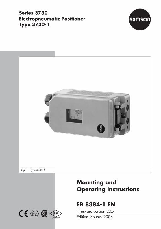
Series 3730Electropneumatic PositionerType 3730-1
Mounting andOperating Instructions
EB 8384-1 ENFirmware version 2.0xEdition January 2006
Fig. 1 · Type 3730-1
Contents Page
1 Design and principle of operation . . . . . . . . . . . . . . . . . . . 6
2 Attachment to the control valve – mounting parts and accessories . . . . 82.1 Direct attachment . . . . . . . . . . . . . . . . . . . . . . . . . . . 122.1.1 Type 3277-5 Actuator. . . . . . . . . . . . . . . . . . . . . . . . . 122.1.2 Type 3277 Actuator . . . . . . . . . . . . . . . . . . . . . . . . . . 142.2 Attachment according to IEC 60534-6 . . . . . . . . . . . . . . . . . 162.3 Attachment to Type 3510 Micro-flow Valve. . . . . . . . . . . . . . . 182.4 Attachment to rotary actuators . . . . . . . . . . . . . . . . . . . . . 202.5 Reversing amplifier for double-acting actuators . . . . . . . . . . . . . 22
3 Connections . . . . . . . . . . . . . . . . . . . . . . . . . . . . . 243.1 Pneumatic connections . . . . . . . . . . . . . . . . . . . . . . . . 243.1.1 Signal pressure gauges . . . . . . . . . . . . . . . . . . . . . . . . 243.1.2 Supply pressure . . . . . . . . . . . . . . . . . . . . . . . . . . . . 243.2 Electrical connections . . . . . . . . . . . . . . . . . . . . . . . . . 26
4 Operation . . . . . . . . . . . . . . . . . . . . . . . . . . . . . . 284.1 Operator controls . . . . . . . . . . . . . . . . . . . . . . . . . . . 28
5 Start-up . . . . . . . . . . . . . . . . . . . . . . . . . . . . . . . 295.1 Setting the volume restriction Q . . . . . . . . . . . . . . . . . . . . . 295.2 Adapting the display . . . . . . . . . . . . . . . . . . . . . . . . . 305.3 Determining the fail-safe position . . . . . . . . . . . . . . . . . . . 305.4 Setting other parameters . . . . . . . . . . . . . . . . . . . . . . . 305.5 Initialization . . . . . . . . . . . . . . . . . . . . . . . . . . . . . 315.6 Faults . . . . . . . . . . . . . . . . . . . . . . . . . . . . . . . . . 325.7 Zero calibration . . . . . . . . . . . . . . . . . . . . . . . . . . . . 33
6 Code list . . . . . . . . . . . . . . . . . . . . . . . . . . . . . . . 34
7 Maintenance . . . . . . . . . . . . . . . . . . . . . . . . . . . . . 38
8 Servicing explosion-protected devices . . . . . . . . . . . . . . . . . 38
9 Dimensions in mm . . . . . . . . . . . . . . . . . . . . . . . . . . 39
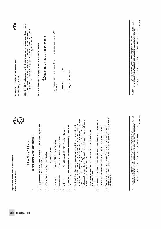
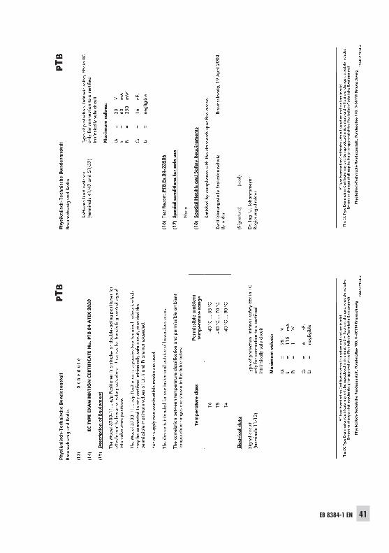
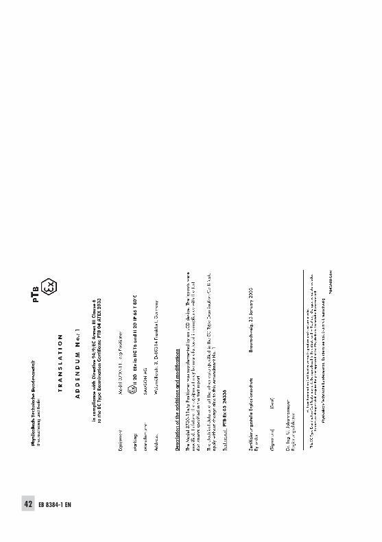
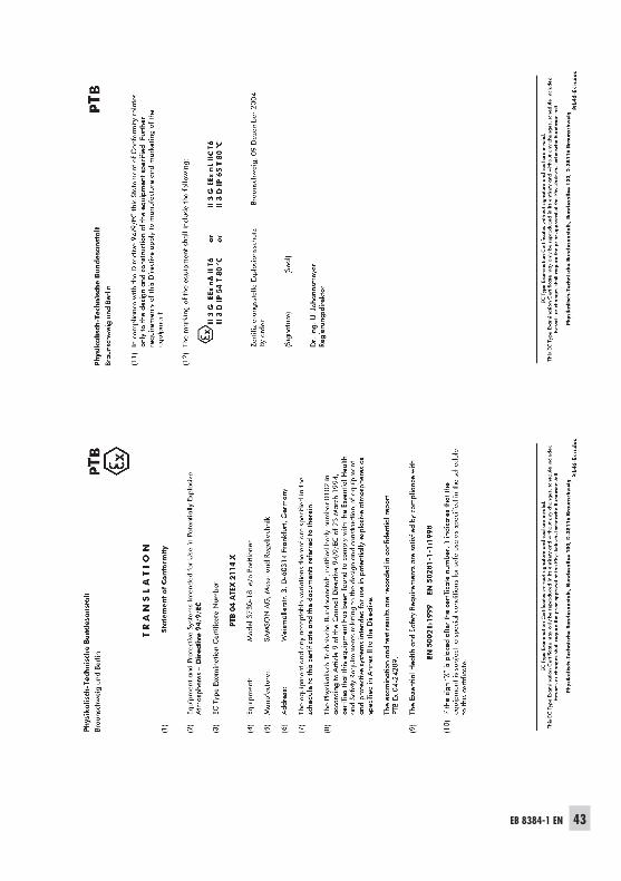
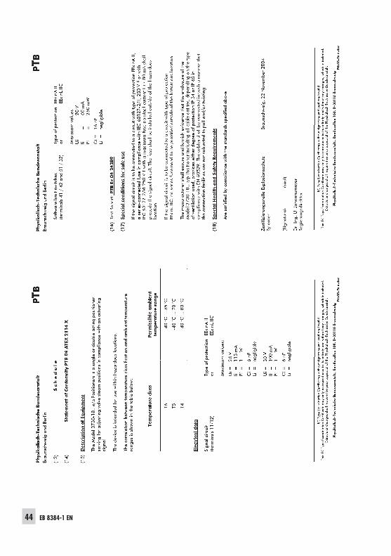
Test certificates . . . . . . . . . . . . . . . . . . . . . . . . . . . . 40
2 EB 8384-1 EN
Contents
EB 8384-1 EN 3
Safety instructions
General safety instructions
� The positioner may only be assembled, started up or operated by trainedand experienced personnel familiar with the product.According to these mounting and operating instructions, trained personnelrefers to individuals who are able to judge the work they are assigned toand recognize possible dangers due to their specialized training, theirknowledge and experience as well as their knowledge of the relevantstandards.
� Explosion-protected versions of this positioner may only be operated bypersonnel who have undergone special training or instructions or who areauthorized to work on explosion-protected devices in hazardous areas.Refer to section 8 on Servicing explosion-protected versions.
� Any hazards that could be caused by the process medium, the operatingpressure, the signal pressure or by moving parts of the control valve are tobe prevented by means of the appropriate measures.
� If inadmissible motions or forces are produced in the actuator as a result ofthe supply pressure level, it must be restricted by means of a suitable supplypressure reducing station.Do not operate the positioner with the back of the positioner/vent openingfacing upwards. The vent opening must not be sealed when the positioner isinstalled on site.
� Proper shipping and appropriate storage are assumed.
� Note! The device with a CE marking fulfils the requirements of the Directives94/9/EC (ATEX) and 89/336/EEC (EMC).The declaration of conformity is available on request.
4 EB 8384-1 EN
Versions
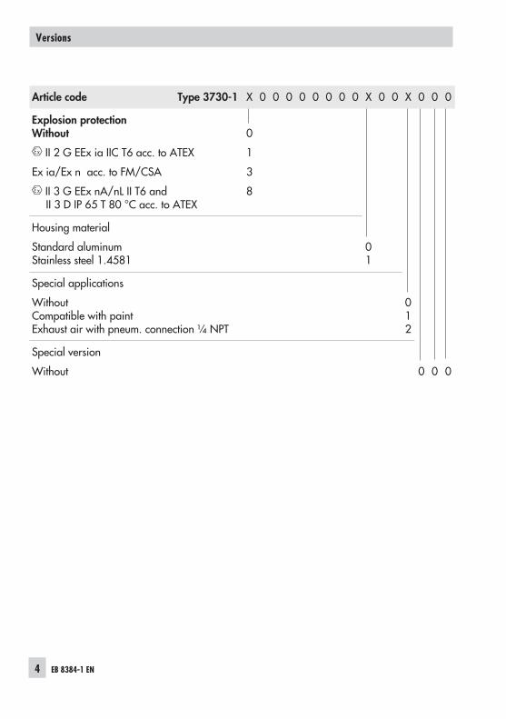
Article code Type 3730-1 X 0 0 0 0 0 0 0 0 X 0 0 X 0 0 0
Explosion protectionWithout
II 2 G EEx ia IIC T6 acc. to ATEX
Ex ia/Ex n acc. to FM/CSA
II 3 G EEx nA/nL II T6 andII 3 D IP 65 T 80 °C acc. to ATEX
0
1
3
8
Housing material
Standard aluminumStainless steel 1.4581
01
Special applications
WithoutCompatible with paintExhaust air with pneum. connection ¼ NPT
012
Special version
Without 0 0 0
EB 8384-1 EN 5
Technical data
Positioner
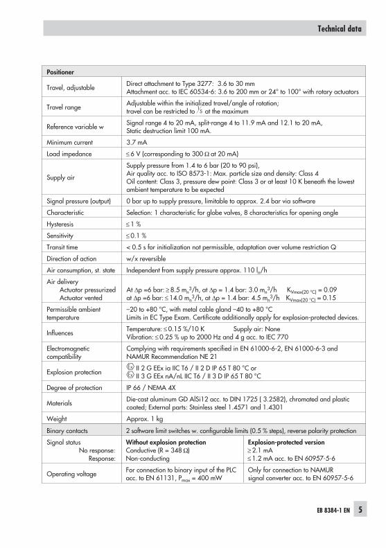
Travel, adjustable Direct attachment to Type 3277: 3.6 to 30 mmAttachment acc. to IEC 60534-6: 3.6 to 200 mm or 24° to 100° with rotary actuators
Travel range Adjustable within the initialized travel/angle of rotation;travel can be restricted to 1
5 at the maximum
Reference variable w Signal range 4 to 20 mA, split-range 4 to 11.9 mA and 12.1 to 20 mA,Static destruction limit 100 mA.
Minimum current 3.7 mA
Load impedance ≤ 6 V (corresponding to 300 Ω at 20 mA)
Supply air
Supply pressure from 1.4 to 6 bar (20 to 90 psi),Air quality acc. to ISO 8573-1: Max. particle size and density: Class 4Oil content: Class 3, pressure dew point: Class 3 or at least 10 K beneath the lowestambient temperature to be expected
Signal pressure (output) 0 bar up to supply pressure, limitable to approx. 2.4 bar via software
Characteristic Selection: 1 characteristic for globe valves, 8 characteristics for opening angle
Hysteresis ≤ 1 %
Sensitivity ≤ 0.1 %
Transit time < 0.5 s for initialization not permissible, adaptation over volume restriction Q
Direction of action w/x reversible
Air consumption, st. state Independent from supply pressure approx. 110 ln/h
Air deliveryActuator pressurizedActuator vented
At Δp =6 bar: ≥ 8.5 mn3/h, at Δp = 1.4 bar: 3.0 mn
3/h KVmax(20 °C) = 0.09at Δp =6 bar: ≤ 14.0 mn
3/h, at Δp = 1.4 bar: 4.5 mn3/h KVmax(20 °C) = 0.15
Permissible ambienttemperature
–20 to +80 °C, with metal cable gland –40 to +80 °CLimits in EC Type Exam. Certificate additionally apply for explosion-protected devices.
Influences Temperature: ≤ 0.15 %/10 K Supply air: NoneVibration: ≤ 0.25 % up to 2000 Hz and 4 g acc. to IEC 770
Electromagneticcompatibility
Complying with requirements specified in EN 61000-6-2, EN 61000-6-3 andNAMUR Recommendation NE 21
Explosion protection II 2 G EEx ia IIC T6 / II 2 D IP 65 T 80 °C orII 3 G EEx nA/nL IIC T6 / II 3 D IP 65 T 80 °C
Degree of protection IP 66 / NEMA 4X
Materials Die-cast aluminum GD AlSi12 acc. to DIN 1725 ( 3.2582), chromated and plasticcoated; External parts: Stainless steel 1.4571 and 1.4301
Weight Approx. 1 kg
Binary contacts 2 software limit switches w. configurable limits (0.5 % steps), reverse polarity protection
Signal statusNo response:
Response:
Without explosion protectionConductive (R = 348 Ω)Non-conducting
Explosion-protected version≥ 2.1 mA≤ 1.2 mA acc. to EN 60957-5-6
Operating voltage For connection to binary input of the PLCacc. to EN 61131, Pmax = 400 mW
Only for connection to NAMURsignal converter acc. to EN 60957-5-6
1 Design and principle ofoperation
The electropneumatic positioner is mountedto pneumatic control valves and is used toassign the valve position (controlledvariable x) to the control signal (referencevariable w). The DC control signal receivedfrom a control unit is compared to the travelor rotational angle of the control valve andissues a signal pressure (output variable y).
The positioner is designed depending on thecorresponding accessories for direct attach-ment to Type 3277 Actuators or for attach-ment to actuators according to IEC 60534-6(NAMUR).Additionally, a coupling wheel included inthe accessories is required to transfer the ro-tary motion for rotary actuators according toVDI/VDE 3845.
Springless rotary actuators require an ac-cessory reversing amplifier to permit thepowered operation in either direction.
The positioner basically consists of a travelsensor system that functions proportional toresistance, an analog i/p module withdownstream booster as well as the electronicunit with a microcontroller. The positioner isfitted with two adjustable software limitswitches as standard to indicate the valve'send positions.
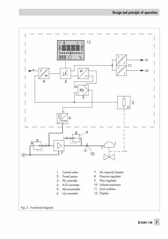
The position of the valve is transmitted aslinear travel motion or angle of rotation viapick-up lever and travel sensor (2) to an an-alog PD controller (3). Simultaneously, anA/D converter (4) transmits the position ofthe valve to the microcontroller (5). The PDcontroller compares this actual position tothe 4 to 20 mA DC control signal (reference
variable) after it has been converted by theA/D converter (4).In case of a system deviation, the operationof the i/p converter (6) is changed so thatthe actuator (1) is filled or vented via thedownstream air capacity booster (7). Thiscauses the closure member of the controlvalve to move to the position determined bythe reference variable.The pneumatic air capacity booster (7) andthe pressure regulator (8) are provided withsupply air. An intermediate flow regulator(9) with fixed settings is used to purge thepositioner and also guarantees trouble-freeoperation of the pneumatic booster.The output signal pressure supplied by thebooster can be limited to 2.4 bar by activat-ing the parameter P9.The volume restriction Q (10) is used to opti-mize the positioner by adapting it to the ac-tuator size.
Tight-closing function:The pneumatic actuator is completely filledwith air or vented as soon as the referencevariable falls below 1 % or exceeds 99 %(see end positions set over parameters P10and P11).
6 EB 8384-1 EN
Design and principle of operation
EB 8384-1 EN 7
Design and principle of operation
Fig. 2 · Functional diagram
%
Smm
%mm
w
x
Q
PD
A2
A1
4 5
3
11
12
6
7
8
10
1
w
9
xy
2
7 Air capacity booster8 Pressure regulator9 Flow regulator10 Volume restriction11 Limit switches12 Display
1 Control valve2 Travel sensor3 PD controller4 A/D converter5 Microcontroller6 i/p converter
2 Attachment to the controlvalve – mounting parts andaccessories
The positioner can be attached either di-rectly to a SAMSON Type 3277 Actuator oraccording to IEC 60534-6 (NAMUR) to con-trol valves with cast yokes or rod-type yokesas well as to rotary actuators according toVDI/VDE 3845.
For attachment to the various actuators, cor-responding mounting parts and accessoriesare required. These are listed with their or-der numbers in Tables 1 to 5.
On attaching the positioner, it is importantto observe the assignment between leverand pin position according to the travelslisted in the travel tables.
The actual valve travel that can be achievedis restricted by the pin position used and ad-ditionally by the actuator spring compres-sion required.The travel range listed in the travel tablescan only achieved if the nominal range is setto MAX.The positioner is standard equipped with thelever M (pin position 35).
Note!If the standard mounted lever M (pin posi-tion 35) is replaced, the newly mounted le-ver must be moved once all the way as faras it will go in both directions to adapt it tothe internal measuring lever.
8 EB 8384-1 EN
Attachment to the control valve – mounting parts and accessories
EB 8384-1 EN 9
Attachment to the control valve – mounting parts and accessories
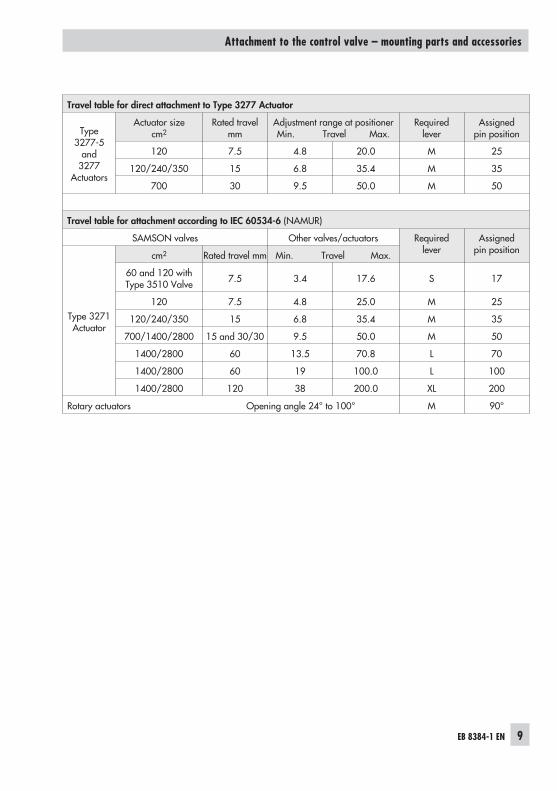
Travel table for direct attachment to Type 3277 Actuator
Type3277-5
and3277
Actuators
Actuator sizecm2
Rated travelmm
Adjustment range at positionerMin. Travel Max.
Requiredlever
Assignedpin position
120 7.5 4.8 20.0 M 25
120/240/350 15 6.8 35.4 M 35
700 30 9.5 50.0 M 50
Travel table for attachment according to IEC 60534-6 (NAMUR)
SAMSON valves Other valves/actuators Requiredlever
Assignedpin position
Type 3271Actuator
cm2 Rated travel mm Min. Travel Max.
60 and 120 withType 3510 Valve 7.5 3.4 17.6 S 17
120 7.5 4.8 25.0 M 25
120/240/350 15 6.8 35.4 M 35
700/1400/2800 15 and 30/30 9.5 50.0 M 50
1400/2800 60 13.5 70.8 L 70
1400/2800 60 19 100.0 L 100
1400/2800 120 38 200.0 XL 200
Rotary actuators Opening angle 24° to 100° M 90°
10 EB 8384-1 EN
Attachment to the control valve – mounting parts and accessories
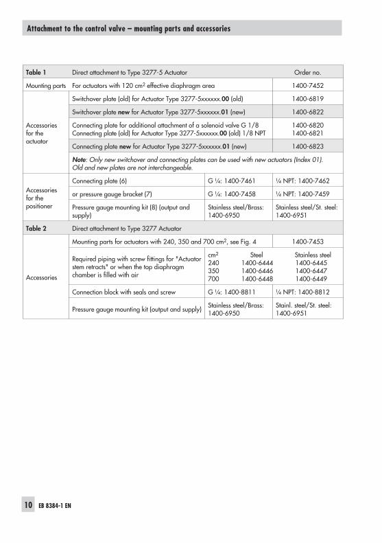
Table 1 Direct attachment to Type 3277-5 Actuator Order no.
Mounting parts For actuators with 120 cm2 effective diaphragm area 1400-7452
Accessoriesfor theactuator
Switchover plate (old) for Actuator Type 3277-5xxxxxx.00 (old) 1400-6819
Switchover plate new for Actuator Type 3277-5xxxxxx.01 (new) 1400-6822
Connecting plate for additional attachment of a solenoid valve G 1/8Connecting plate (old) for Actuator Type 3277-5xxxxxx.00 (old) 1/8 NPT
1400-68201400-6821
Connecting plate new for Actuator Type 3277-5xxxxxx.01 (new) 1400-6823
Note: Only new switchover and connecting plates can be used with new actuators (Index 01).Old and new plates are not interchangeable.
Accessoriesfor thepositioner
Connecting plate (6) G ¼: 1400-7461 ¼ NPT: 1400-7462
or pressure gauge bracket (7) G ¼: 1400-7458 ¼ NPT: 1400-7459
Pressure gauge mounting kit (8) (output andsupply)
Stainless steel/Brass:1400-6950
Stainless steel/St. steel:1400-6951
Table 2 Direct attachment to Type 3277 Actuator
Accessories
Mounting parts for actuators with 240, 350 and 700 cm2, see Fig. 4 1400-7453
Required piping with screw fittings for "Actuatorstem retracts" or when the top diaphragmchamber is filled with air
cm2 Steel Stainless steel240 1400-6444 1400-6445350 1400-6446 1400-6447700 1400-6448 1400-6449
Connection block with seals and screw G ¼: 1400-8811 ¼ NPT: 1400-8812
Pressure gauge mounting kit (output and supply) Stainless steel/Brass:1400-6950
Stainl. steel/St. steel:1400-6951
EB 8384-1 EN 11
Attachment to the control valve – mounting parts and accessories
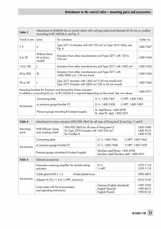
Table 4 Attachment to rotary actuators (VDI/VDE 3845 for all sizes of fixing level 2) see Figs. 7 and 8
Mountingparts
With follower clampand coupling wheel
VDI/VDE 3845 for all sizes of fixing level 2for Type 3278 Actuator with 160/320 cm2
for Camflex II
1400-74481400-76141400-9120
Accessories
Connecting plate G ¼: 1400-7461 ¼ NPT: 1400-7462
or pressure gauge bracket (7) G ¼: 1400-7458 ¼ NPT: 1400-7459
Pressure gauge mounting kit (output/supply) Stainless steel/Brass: 1400-6950Stainless steel/Stainless steel: 1400-6951
Table 5 General accessories
Accessories
Pneumatic reversing amplifier for double-actingactuators
G ¼¼ NPT
1079-11181079-1119
Cable gland M20 x 1.5 Nickel-plated brass 1890-4875
Adapter M 20 x 1.5 to ½ NPT, aluminum 0310-2149
Cover plate with list of parametersand operating instructions
German/English (standard)English/SpanishEnglish/French
1990-79301990-82121990-8132
Table 3 Attachment to NAMUR ribs or control valves with rod-type yokes (rod diameter Ø 35 mm or smaller)according to IEC 60534-6, see Fig. 5
Travel in mm Lever For actuators Order no.
7.5 S Type 3271-5 Actuator with 60/120 cm2 on Type 3510 Valve, seeFig. 6 1400-7457
5 to 50Without (leverM on basicmodel)
Actuators from other manufacturers and Type 3271 with 120 to700 cm2 1400-7454
14 to 100 L Actuators from other manufacturers and Type 3271 with 1400 cm2 1400-7455
40 to 200 XL Actuators from other manufacturers and Type 3271 with1400/2800 cm2, 120 mm travel 1400-7456
30 or 60 L Type 3271 Actuator with 1400 cm2 (120 mm travel) andType 3271 Actuator with 2800 cm2 (30 or 60 mm travel) 1400-7466
Mounting brackets for Emerson and Masoneilan linear actuatorsIn addition, a mounting kit acc. to IEC 60534-6 is required depending on the travel. See row above. 1400-6771
Accessories
Connecting plate G ¼: 1400-7461 ¼ NPT: 1400-7462
or pressure gauge bracket (7) G ¼: 1400-7458 ¼ NPT: 1400-7459
Pressure gauge mounting kit (output/supply) St. steel/Brass: 1400-6950St. steel/St. steel: 1400-6951
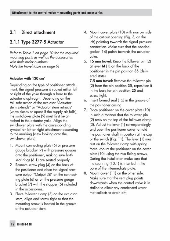
2.1 Direct attachment
2.1.1 Type 3277-5 Actuator
Refer to Table 1 on page 10 for the requiredmounting parts as well as the accessorieswith their order numbers.Note the travel table on page 9!
Actuator with 120 cm²
Depending on the type of positioner attach-ment, the signal pressure is routed either leftor right of the yoke through a bore to theactuator diaphragm. Depending on thefail-safe action of the actuator "Actuatorstem extends" or "Actuator stem retracts"(valve closes or opens if the supply air fails),the switchover plate (9) must first be at-tached to the actuator yoke. Align theswitchover plate with the correspondingsymbol for left or right attachment accordingto the marking (view looking onto theswitchover plate).
1. Mount connecting plate (6) or pressuregauge bracket (7) with pressure gaugesonto the positioner, making sure bothseal rings (6.1) are seated properly.
2. Remove screw plug (4) on the back ofthe positioner and close the signal pres-sure output "Output 38" on the connect-ing plate (6) or on the pressure gaugebracket (7) with the stopper (5) includedin the accessories.
3. Place follower clamp (3) on the actuatorstem, align and screw tight so that themounting screw is located in the grooveof the actuator stem.
4. Mount cover plate (10) with narrow sideof the cut-out opening (Fig. 3, on theleft) pointing towards the signal pressureconnection. Make sure that the bondedgasket (14) points towards the actuatoryoke.
5. 15 mm travel: Keep the follower pin (2)at lever M (1) on the back of thepositioner in the pin position 35 (deliv-ered state).7.5 mm travel: Remove the follower pin(2) from the pin position 35, reposition itin the bore for pin position 25 andscrew tight.
6. Insert formed seal (15) in the groove ofthe positioner casing.
7. Place positioner on the cover plate (10)in such a manner that the follower pin(2) rests on the top of the follower clamp(3). Adjust the lever (1) correspondinglyand open the positioner cover to holdthe positioner shaft in position at the capor the switch (Fig. 11). The lever (1) mustrest on the follower clamp with springforce. Mount the positioner on the coverplate (10) using the two fixing screws.During the installation make sure thatthe seal ring (10.1) is inserted in thebore of the intermediate plate.
8. Mount cover (11) on the other side.Make sure that the vent plug pointsdownwards when the control valve is in-stalled to allow any condensed waterthat collects to drain off.
12 EB 8384-1 EN
Attachment to the control valve – mounting parts and accessories
EB 8384-1 EN 13
Attachment to the control valve – mounting parts and accessories
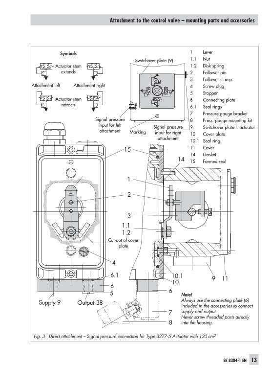
Fig. 3 · Direct attachment – Signal pressure connection for Type 3277-5 Actuator with 120 cm2
9 11
Supply 9 Output 38
56
4
7
61010.1
3
2
1
15
6.1
1.11.2
14
8
1 Lever1.1 Nut1.2 Disk spring2 Follower pin3 Follower clamp4 Screw plug5 Stopper6 Connecting plate6.1 Seal rings7 Pressure gauge bracket8 Press. gauge mounting kit9 Switchover plate f. actuator10 Cover plate10.1 Seal ring11 Cover14 Gasket15 Formed seal
Note!Always use the connecting plate (6)included in the accessories to connectsupply and output.Never screw threaded parts directlyinto the housing.
Symbols
Actuator stemextends
Attachment left Attachment right
Actuator stemretracts
Switchover plate (9)
Signal pressureinput for right
attachmentMarking
Cut-out of coverplate
Signal pressureinput for leftattachment
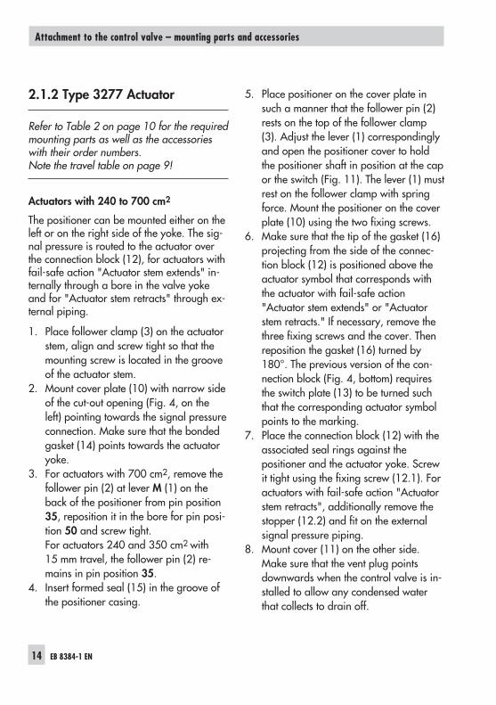
2.1.2 Type 3277 Actuator
Refer to Table 2 on page 10 for the requiredmounting parts as well as the accessorieswith their order numbers.Note the travel table on page 9!
Actuators with 240 to 700 cm2
The positioner can be mounted either on theleft or on the right side of the yoke. The sig-nal pressure is routed to the actuator overthe connection block (12), for actuators withfail-safe action "Actuator stem extends" in-ternally through a bore in the valve yokeand for "Actuator stem retracts" through ex-ternal piping.
1. Place follower clamp (3) on the actuatorstem, align and screw tight so that themounting screw is located in the grooveof the actuator stem.
2. Mount cover plate (10) with narrow sideof the cut-out opening (Fig. 4, on theleft) pointing towards the signal pressureconnection. Make sure that the bondedgasket (14) points towards the actuatoryoke.
3. For actuators with 700 cm2, remove thefollower pin (2) at lever M (1) on theback of the positioner from pin position35, reposition it in the bore for pin posi-tion 50 and screw tight.For actuators 240 and 350 cm2 with15 mm travel, the follower pin (2) re-mains in pin position 35.
4. Insert formed seal (15) in the groove ofthe positioner casing.
5. Place positioner on the cover plate insuch a manner that the follower pin (2)rests on the top of the follower clamp(3). Adjust the lever (1) correspondinglyand open the positioner cover to holdthe positioner shaft in position at the capor the switch (Fig. 11). The lever (1) mustrest on the follower clamp with springforce. Mount the positioner on the coverplate (10) using the two fixing screws.
6. Make sure that the tip of the gasket (16)projecting from the side of the connec-tion block (12) is positioned above theactuator symbol that corresponds withthe actuator with fail-safe action"Actuator stem extends" or "Actuatorstem retracts." If necessary, remove thethree fixing screws and the cover. Thenreposition the gasket (16) turned by180°. The previous version of the con-nection block (Fig. 4, bottom) requiresthe switch plate (13) to be turned suchthat the corresponding actuator symbolpoints to the marking.
7. Place the connection block (12) with theassociated seal rings against thepositioner and the actuator yoke. Screwit tight using the fixing screw (12.1). Foractuators with fail-safe action "Actuatorstem retracts", additionally remove thestopper (12.2) and fit on the externalsignal pressure piping.
8. Mount cover (11) on the other side.Make sure that the vent plug pointsdownwards when the control valve is in-stalled to allow any condensed waterthat collects to drain off.
14 EB 8384-1 EN
Attachment to the control valve – mounting parts and accessories
EB 8384-1 EN 15
Attachment to the control valve – mounting parts and accessories
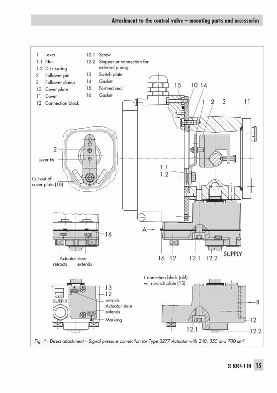
Fig. 4 · Direct attachment – Signal pressure connection for Type 3277 Actuator with 240, 350 and 700 cm2
2
10 1415
1 2 3 11
SUPPLY
13
16
B
1.11.2
1212.1
12
12.1
12.2
A
1216 12.2SUPPLY
1 Lever1.1 Nut1.2 Disk spring2 Follower pin3 Follower clamp10 Cover plate11 Cover12 Connection block
12.1 Screw12.2 Stopper or connection for
external piping13 Switch plate14 Gasket15 Formed seal16 Gasket
Cut-out ofcover plate (10)
Actuator stemretracts extends
retractsActuator stemextends
Marking
Connection block (old)with switch plate (13)
Lever M
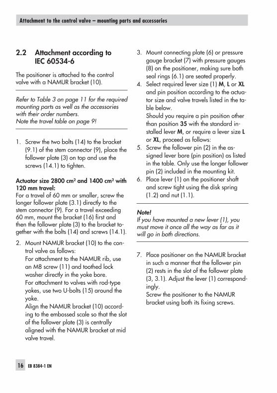
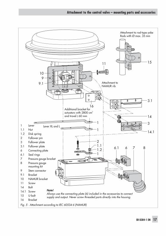
2.2 Attachment according toIEC 60534-6
The positioner is attached to the controlvalve with a NAMUR bracket (10).
Refer to Table 3 on page 11 for the requiredmounting parts as well as the accessorieswith their order numbers.Note the travel table on page 9!
1. Screw the two bolts (14) to the bracket(9.1) of the stem connector (9), place thefollower plate (3) on top and use thescrews (14.1) to tighten.
Actuator size 2800 cm² and 1400 cm² with120 mm travel:For a travel of 60 mm or smaller, screw thelonger follower plate (3.1) directly to thestem connector (9). For a travel exceeding60 mm, mount the bracket (16) first andthen the follower plate (3) to the bracket to-gether with the bolts (14) and screws (14.1).
2. Mount NAMUR bracket (10) to the con-trol valve as follows:For attachment to the NAMUR rib, usean M8 screw (11) and toothed lockwasher directly in the yoke bore.For attachment to valves with rod-typeyokes, use two U-bolts (15) around theyoke.Align the NAMUR bracket (10) accord-ing to the embossed scale so that the slotof the follower plate (3) is centrallyaligned with the NAMUR bracket at midvalve travel.
3. Mount connecting plate (6) or pressuregauge bracket (7) with pressure gauges(8) on the positioner, making sure bothseal rings (6.1) are seated properly.
4. Select required lever size (1) M, L or XLand pin position according to the actua-tor size and valve travels listed in the ta-ble below.Should you require a pin position otherthan position 35 with the standard in-stalled lever M, or require a lever size Lor XL, proceed as follows:
5. Screw the follower pin (2) in the as-signed lever bore (pin position) as listedin the table. Only use the longer followerpin (2) included in the mounting kit.
6. Place lever (1) on the positioner shaftand screw tight using the disk spring(1.2) and nut (1.1).
Note!If you have mounted a new lever (1), youmust move it once all the way as far as itwill go in both directions.
7. Place positioner on the NAMUR bracketin such a manner that the follower pin(2) rests in the slot of the follower plate(3, 3.1). Adjust the lever (1) correspond-ingly.Screw the positioner to the NAMURbracket using both its fixing screws.
16 EB 8384-1 EN
Attachment to the control valve – mounting parts and accessories
EB 8384-1 EN 17
Attachment to the control valve – mounting parts and accessories
Fig. 5 · Attachment according to IEC 60534-6 (NAMUR)
10
11
6.1 6 7 8
1
1 14.1
3
3.1
16
15
14
11.21.12
9.19
1 Lever1.1 Nut1.2 Disk spring2 Follower pin3 Follower plate3.1 Follower plate6 Connecting plate6.1 Seal rings7 Pressure gauge bracket8 Pressure gauge
mounting kit9 Stem connector9.1 Bracket10 NAMUR bracket11 Screw14 Bolt14.1 Screw15 U-bolt16 Bracket
Note!Always use the connecting plate (6) included in the accessories to connectsupply and output. Never screw threaded parts directly into the housing.
Attachment toNAMUR rib
Additional bracket foractuators with 2800 cm2
and travel ≥ 60 mm
Attachment to rod-type yokeRods with Ø max. 35 mm
Lever XL and L
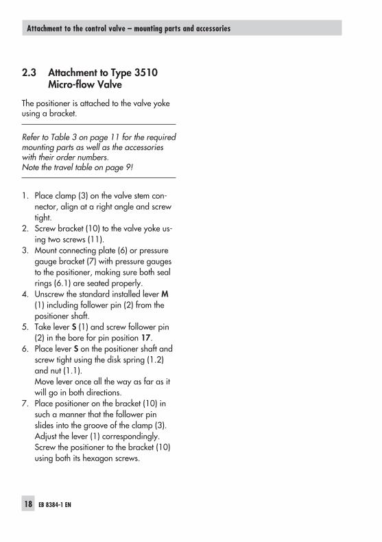
2.3 Attachment to Type 3510Micro-flow Valve
The positioner is attached to the valve yokeusing a bracket.
Refer to Table 3 on page 11 for the requiredmounting parts as well as the accessorieswith their order numbers.Note the travel table on page 9!
1. Place clamp (3) on the valve stem con-nector, align at a right angle and screwtight.
2. Screw bracket (10) to the valve yoke us-ing two screws (11).
3. Mount connecting plate (6) or pressuregauge bracket (7) with pressure gaugesto the positioner, making sure both sealrings (6.1) are seated properly.
4. Unscrew the standard installed lever M(1) including follower pin (2) from thepositioner shaft.
5. Take lever S (1) and screw follower pin(2) in the bore for pin position 17.
6. Place lever S on the positioner shaft andscrew tight using the disk spring (1.2)and nut (1.1).Move lever once all the way as far as itwill go in both directions.
7. Place positioner on the bracket (10) insuch a manner that the follower pinslides into the groove of the clamp (3).Adjust the lever (1) correspondingly.Screw the positioner to the bracket (10)using both its hexagon screws.
18 EB 8384-1 EN
Attachment to the control valve – mounting parts and accessories
EB 8384-1 EN 19
Attachment to the control valve – mounting parts and accessories
Fig. 6 · Attachment to Type 3510 Micro-flow Valve
3
10
11
11
6
121.2 1.1
78
6.1
1 Lever1.1 Nut1.2 Disk spring2 Follower pin3 Clamp6 Connecting plate6.1 Seal rings7 Pressure gauge bracket8 Pressure gauge
mounting kit10 Bracket11 Screw
Note!Always use the connecting plate (6)included in the accessories to connectsupply and output.Never screw threaded parts directlyinto the housing.
Lever S
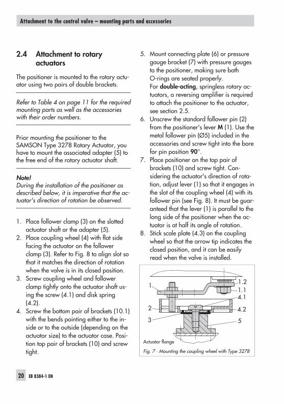
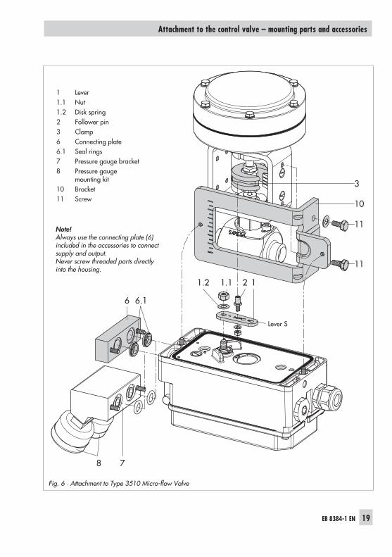
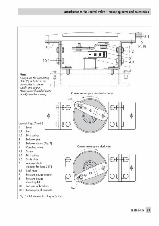
2.4 Attachment to rotaryactuators
The positioner is mounted to the rotary actu-ator using two pairs of double brackets.
Refer to Table 4 on page 11 for the requiredmounting parts as well as the accessorieswith their order numbers.
Prior mounting the positioner to theSAMSON Type 3278 Rotary Actuator, youhave to mount the associated adapter (5) tothe free end of the rotary actuator shaft.
Note!During the installation of the positioner asdescribed below, it is imperative that the ac-tuator's direction of rotation be observed.
1. Place follower clamp (3) on the slottedactuator shaft or the adapter (5).
2. Place coupling wheel (4) with flat sidefacing the actuator on the followerclamp (3). Refer to Fig. 8 to align slot sothat it matches the direction of rotationwhen the valve is in its closed position.
3. Screw coupling wheel and followerclamp tightly onto the actuator shaft us-ing the screw (4.1) and disk spring(4.2).
4. Screw the bottom pair of brackets (10.1)with the bends pointing either to the in-side or to the outside (depending on theactuator size) to the actuator case. Posi-tion top pair of brackets (10) and screwtight.
5. Mount connecting plate (6) or pressuregauge bracket (7) with pressure gaugesto the positioner, making sure bothO-rings are seated properly.For double-acting, springless rotary ac-tuators, a reversing amplifier is requiredto attach the positioner to the actuator,see section 2.5.
6. Unscrew the standard follower pin (2)from the positioner's lever M (1). Use themetal follower pin (Ø5) included in theaccessories and screw tight into the borefor pin position 90°.
7. Place positioner on the top pair ofbrackets (10) and screw tight. Con-sidering the actuator's direction of rota-tion, adjust lever (1) so that it engages inthe slot of the coupling wheel (4) with itsfollower pin (see Fig. 8). It must be guar-anteed that the lever (1) is parallel to thelong side of the positioner when the ac-tuator is at half its angle of rotation.
8. Stick scale plate (4.3) on the couplingwheel so that the arrow tip indicates theclosed position, and it can be easilyread when the valve is installed.
20 EB 8384-1 EN
Attachment to the control valve – mounting parts and accessories
Fig. 7 · Mounting the coupling wheel with Type 3278
1.21.1
1
2
4.1
4.2
53
Actuator flange
EB 8384-1 EN 21
Attachment to the control valve – mounting parts and accessories
Fig. 8 · Attachment to rotary actuators
10
10.1
6(7, 8)
1.124.3
5
6.1
4
1.21
Note!Always use the connectingplate (6) included in theaccessories to connectsupply and output.Never screw threaded partsdirectly into the housing.
Legends Figs. 7 and 81 Lever1.1 Nut1.2 Disk spring2 Follower pin3 Follower clamp (Fig. 7)4 Coupling wheel4.1 Screw4.2 Disk spring4.3 Scale plate5 Actuator shaft
Adapter for Type 32786.1 Seal rings7 Pressure gauge bracket8 Pressure gauge
mounting kit10 Top pair of brackets10.1 Bottom pair of brackets
Control valve opens clockwise
Control valve opens counterclockwise
Slot
Slot
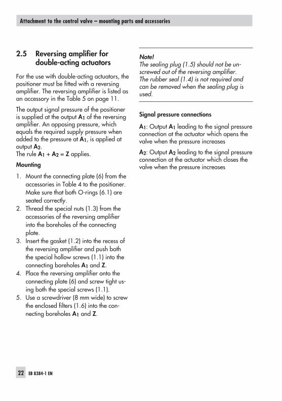
2.5 Reversing amplifier fordouble-acting actuators
For the use with double-acting actuators, thepositioner must be fitted with a reversingamplifier. The reversing amplifier is listed asan accessory in the Table 5 on page 11.
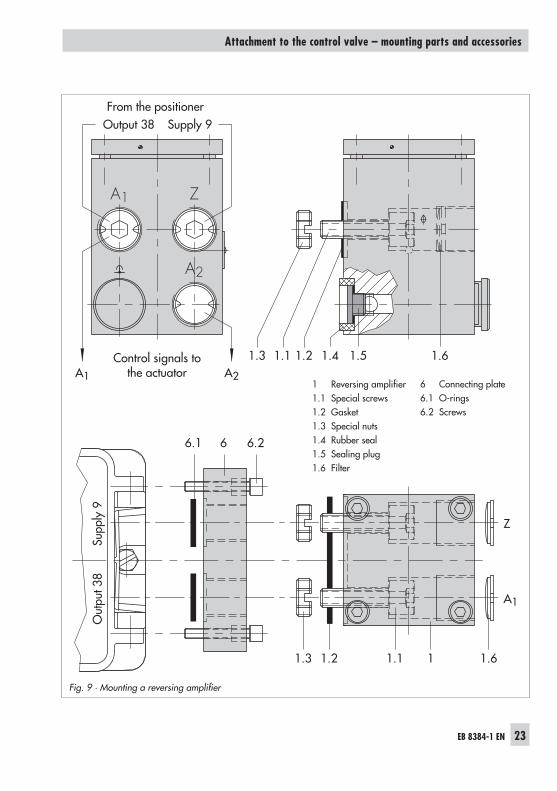
The output signal pressure of the positioneris supplied at the output A1 of the reversingamplifier. An opposing pressure, whichequals the required supply pressure whenadded to the pressure at A1, is applied atoutput A2.The rule A1 + A2 = Z applies.
Mounting
1. Mount the connecting plate (6) from theaccessories in Table 4 to the positioner.Make sure that both O-rings (6.1) areseated correctly.
2. Thread the special nuts (1.3) from theaccessories of the reversing amplifierinto the boreholes of the connectingplate.
3. Insert the gasket (1.2) into the recess ofthe reversing amplifier and push boththe special hollow screws (1.1) into theconnecting boreholes A1 and Z.
4. Place the reversing amplifier onto theconnecting plate (6) and screw tight us-ing both the special screws (1.1).
5. Use a screwdriver (8 mm wide) to screwthe enclosed filters (1.6) into the con-necting boreholes A1 and Z.
Note!The sealing plug (1.5) should not be un-screwed out of the reversing amplifier.The rubber seal (1.4) is not required andcan be removed when the sealing plug isused.
Signal pressure connections
A1: Output A1 leading to the signal pressureconnection at the actuator which opens thevalve when the pressure increases
A2: Output A2 leading to the signal pressureconnection at the actuator which closes thevalve when the pressure increases
22 EB 8384-1 EN
Attachment to the control valve – mounting parts and accessories
EB 8384-1 EN 23
Attachment to the control valve – mounting parts and accessories
Fig. 9 · Mounting a reversing amplifier
A1
1.5 1.6
1.3
6.266.1
1.2 1.1 1 1.6
Z
A2
1.4A1 A2
Z
A1
Output 38 Supply 9
Out
put 3
8Su
pply
9
1.3 1.21.1
1 Reversing amplifier1.1 Special screws1.2 Gasket1.3 Special nuts1.4 Rubber seal1.5 Sealing plug1.6 Filter
6 Connecting plate6.1 O-rings6.2 Screws
From the positioner
Control signals tothe actuator
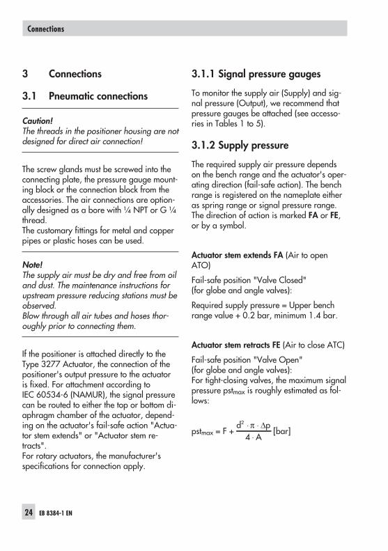
3 Connections
3.1 Pneumatic connections
Caution!The threads in the positioner housing are notdesigned for direct air connection!
The screw glands must be screwed into theconnecting plate, the pressure gauge mount-ing block or the connection block from theaccessories. The air connections are option-ally designed as a bore with ¼ NPT or G ¼thread.The customary fittings for metal and copperpipes or plastic hoses can be used.
Note!The supply air must be dry and free from oiland dust. The maintenance instructions forupstream pressure reducing stations must beobserved.Blow through all air tubes and hoses thor-oughly prior to connecting them.
If the positioner is attached directly to theType 3277 Actuator, the connection of thepositioner's output pressure to the actuatoris fixed. For attachment according toIEC 60534-6 (NAMUR), the signal pressurecan be routed to either the top or bottom di-aphragm chamber of the actuator, depend-ing on the actuator's fail-safe action "Actua-tor stem extends" or "Actuator stem re-tracts".For rotary actuators, the manufacturer'sspecifications for connection apply.
3.1.1 Signal pressure gauges
To monitor the supply air (Supply) and sig-nal pressure (Output), we recommend thatpressure gauges be attached (see accesso-ries in Tables 1 to 5).
3.1.2 Supply pressure
The required supply air pressure dependson the bench range and the actuator's oper-ating direction (fail-safe action). The benchrange is registered on the nameplate eitheras spring range or signal pressure range.The direction of action is marked FA or FE,or by a symbol.
Actuator stem extends FA (Air to openATO)
Fail-safe position "Valve Closed"(for globe and angle valves):
Required supply pressure = Upper benchrange value + 0.2 bar, minimum 1.4 bar.
Actuator stem retracts FE (Air to close ATC)
Fail-safe position "Valve Open"(for globe and angle valves):For tight-closing valves, the maximum signalpressure pstmax is roughly estimated as fol-lows:
pstmax = F +d p
A
2
4⋅ ⋅
⋅π Δ
[bar]
24 EB 8384-1 EN
Connections
d = Seat diameter [cm]Δp = Differential pressure across the valve
[bar]A = Actuator diaphragm area [cm2]F = Upper bench range of the actuator
[bar]
If there are no specifications, calculate asfollows:
Required supply pressure =Upper bench range value + 1 bar
Note!The signal pressure at the output(Output 38) of the positioner can be limitedto approx. 2.4 bar by setting the parameterP9 = ON.
EB 8384-1 EN 25
Connections
3.2 Electrical connections
For electrical installation, you are re-quired to observe the relevant elec-trotechnical regulations and the acci-dent prevention regulations that ap-ply in the country of use. In Germa-ny, these are the VDE regulationsand the accident prevention regula-tions of the employers' liability insu-rance association.The following standards apply for in-stallation in hazardous areas:EN 60079-14: 2003 (VDE 0165Part 1) "Electrical apparatus for ex-plosive gas atmospheres" andEN 50281-1-2: 1999 (VDE 0165Part 2) "Electrical apparatus for usein the presence of combustibledust".For the interconnection of intrinsical-ly safe electrical equipment, the per-missible maximum values specifiedin the EC type examination certifica-te apply (Ui or Uo; Ii or Io; Pi or Po; Cior Co, and Li or Lo).For EEx nA equipment (non-sparkingapparatus), the standard EN 50021:1999 specifies that connecting, inter-rupting, or switching circuits whileenergized is only allowed during in-stallation, maintenance or repairwork.For EEx nL equipment (energy-limit-ed apparatus), the standardEN 50021: 1999 allows this type ofequipment to be switched under nor-mal operating conditions.
Caution!The terminal assignment specified in the cer-tificate must be adhered to. Reversing theassignment of the electrical terminals maycause the explosion protection to become in-effective!Do not tamper with enameled screws insideor on the housing.
Note on the selection of cables and wires:To install intrinsically safe circuits, observesection 12 of the standard EN 60079-14:2003 (VDE 0165 Part 1). To run multi-corecables or lines with more than one intrinsi-cally safe circuit, section 12.2.2.7 of thisstandard applies.An additional cable gland can be installedwhen connecting the device over two sepa-rate cables. Cable entries left unused mustbe sealed with blanking plugs. Devices usedat ambient temperatures down to –40 °Cmust have metal cable entries.
Cable entries
The cable entry with M20x1.5 cable gland,6 to 12 mm clamping area.There is a second M20x1.5 threaded borein the housing that can be used for addi-tional connection, when required.The screw terminals are designed for wirecross-sections of 0.2 to 2.5 mm². Tighten byat least 0.5 Nm.
The wires for the reference variable must beconnected to the terminals 11 and 12 lo-cated in the housing. Only use a currentsource!
26 EB 8384-1 EN
Connections
Caution!The erroneous connection of a voltagesource of just around 7 V (or around 2 Vwhen connected to the wrong pole) candamage the positioner.
In general, it is not necessary to connect thepositioner to a bonding conductor. Shouldthis be required, however, this conductorcan be connected inside the device.
For operation of the limit switches in Type3730-11/-13/-18 Positioners, switchingamplifiers which comply withEN 60947-5-6 must be connected to termi-nals 41/42 and 51/52 in the output circuit.If the positioner is to be installed in hazard-ous areas, the relevant regulations must beobserved.
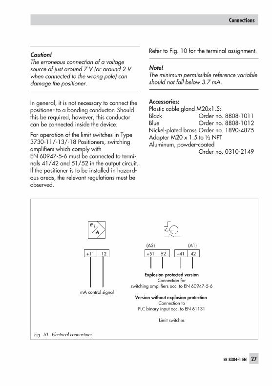
Refer to Fig. 10 for the terminal assignment.
Note!The minimum permissible reference variableshould not fall below 3.7 mA.
Accessories:Plastic cable gland M20x1.5:Black Order no. 8808-1011Blue Order no. 8808-1012Nickel-plated brass Order no. 1890-4875Adapter M20 x 1.5 to ½ NPTAluminum, powder-coated
Order no. 0310-2149
EB 8384-1 EN 27
Connections
Fig. 10 · Electrical connections
+11 -12 +51 -52 +41 -42
(A2) (A1)
mA control signal
Explosion-protected versionConnection for
switching amplifiers acc. to EN 60947-5-6
Version without explosion protectionConnection to
PLC binary input acc. to EN 61131
Limit switches
4 Operation
The positioner is mainly operated with therotary pushbutton.The volume restriction must be set first toadapt the air delivery.
4.1 Operator controls
Rotary pushbutton
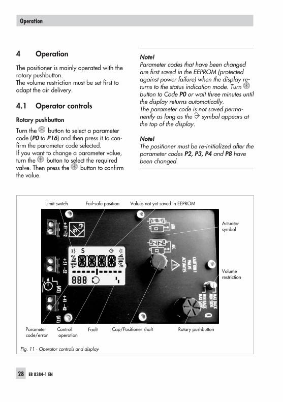
Turn the button to select a parametercode (P0 to P16) and then press it to con-firm the parameter code selected.If you want to change a parameter value,turn the button to select the requiredvalve. Then press the button to confirmthe value.
Note!Parameter codes that have been changedare first saved in the EEPROM (protectedagainst power failure) when the display re-turns to the status indication mode. Turnbutton to Code P0 or wait three minutes untilthe display returns automatically.The parameter code is not saved perma-nently as long as the symbol appears atthe top of the display.
Note!The positioner must be re-initialized after theparameter codes P2, P3, P4 and P8 havebeen changed.
28 EB 8384-1 EN
Operation
Fig. 11 · Operator controls and display
Volumerestriction
Actuatorsymbol
Cap/Positioner shaft Rotary pushbutton
Limit switch Fail-safe position Values not yet saved in EEPROM
FaultControloperation
Parametercode/error
Volume restriction Q
The volume restriction is used to adapt theair delivery to the actuator size. Two fixedsettings are possible depending on how theair is routed at the actuator. See section 5.1for more details.
Display
The LC display indicates symbols that areassigned to codes and functions. The bargraph indicates the system deviation thatdepends on the sign (+/–) and the value.One bar graph element appears per 1 %system deviation.If the positioner is not initialized, the leverposition in degrees in relation to the longitu-dinal axis is indicated instead of the systemdeviation. One bar graph element corre-sponds to approximately a 5° angle.
If the fault symbol appears on the dis-play, turn the button until ERR appearsto view the error code(s) E0 to E15. Refer tosection 5.6 for details.
5 Start-up
Warning!Do not perform a start-up while theprocess is running.On applying supply air and the elec-tric control signal, the control valvemay move through its entire travelrange/rotational angle range de-pending on the setting.
� Connect the supply air (Supply 9).� Apply the electric reference variable 4 to
20 mA (terminals 11 and 12).
Note! For most applications, the positioneris ready for operation with its default set-tings, provided it is attached properly.The positioner just needs to be initialized af-ter the volume restriction has been set andthe fail-safe position has been determined.
5.1 Setting the volume restriction Q
The volume restriction Q is used to adapt theair delivery to the size of the actuator:
� Actuators with a transit time < 1 s, e.g.linear actuators with an effective areasmaller than 240 cm², require a re-stricted air flow rate (MIN).
� Actuators with a transit time ≥ 1 s do notrequire the air flow rate to be restricted(MAX).
The position of volume restriction Q also de-pends on how the signal pressure is routedat the actuator in SAMSON actuators:
EB 8384-1 EN 29
Start-up
� The “SIDE“ position applies for actuatorswith a loading pressure connection at theside, e.g. Type 3271-5.
� The “BACK“ position applies for actua-tors with a loading pressure connectionat the back, e.g. in Type 3277-5.
The “SIDE” restriction position always appliesfor actuators from other manufacturers.
Overview · Position of the volume restriction*
Signalpressure
Transittime
< 1 s ≥ 1 s
Connection at the side MIN SIDE MAX SIDE
Connection at the back MIN BACK MAX BACK
* Intermediate positions are not permitted.
Note! The positioner needs to be initializedagain after the position of the restriction hasbeen changed.
5.2 Adapting the display
The data representation on the positionerdisplay can be turned by 180°.If the displayed data appear upside down,proceed as follows:
Turn the button until Code P1 appears,
press button to confirm the selectedcode. P1 blinks.
Reading direction for rightattachment of pneumaticconnections
Turn button until the display is adjustedto the desired direction, then confirm rea-ding direction by pressing the button.
5.3 Determining the fail-safeposition
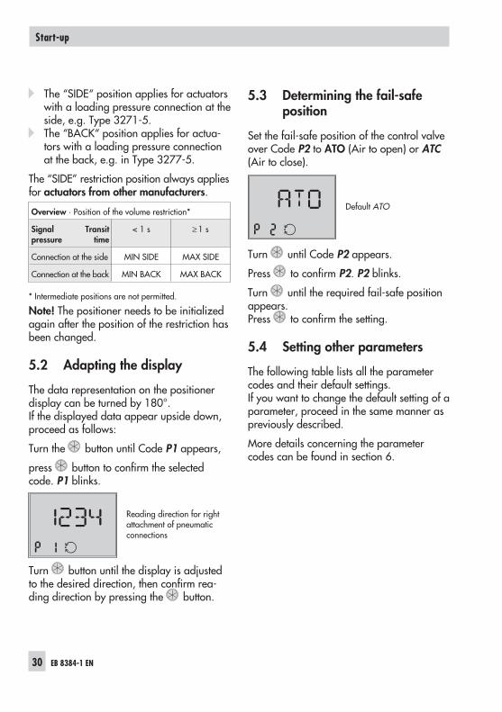
Set the fail-safe position of the control valveover Code P2 to ATO (Air to open) or ATC(Air to close).
Default ATO
Turn until Code P2 appears.
Press to confirm P2. P2 blinks.
Turn until the required fail-safe positionappears.Press to confirm the setting.
5.4 Setting other parameters
The following table lists all the parametercodes and their default settings.If you want to change the default setting of aparameter, proceed in the same manner aspreviously described.
More details concerning the parametercodes can be found in section 6.
30 EB 8384-1 EN
Start-up
5.5 Initialization
During initialization the positioner adapts it-self optimally to the friction conditions andthe signal pressure demand of the controlvalve.The type and extent of self-adaptation de-pends on the preset parameters.MAX is the default setting for the nominalrange (Code P4). During the initializationprocess, the positioner determines thetravel/rotational angle of the closing ele-ment from the CLOSED position as far as itwill go in the other direction.
Note!For standard operation, after the positioneris mounted on the valve and the volume re-striction has been set and the fail-safe posi-tion has been checked over Code P2, startinitialization over Code P15 to ensure theoptimal functioning of the positioner.The positioner works with its standard set-tings (default settings).
Warning!During the initialization, the controlvalve moves through its entire tra-vel/angle of rotation range. Therefo-re, do not start initialization while aprocess is running, but only duringstart-up, when all shut-off valves areclosed.
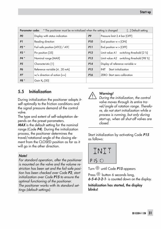
Start initialization by activating Code P15as follows:
Turn until Code P15 appears
Press button 6 seconds long,6-5-4-3-2-1- is counted down on the display.
Initialization has started, the displayblinks!
EB 8384-1 EN 31
Start-up
Parameter codes * The positioner must be re-initialized when the setting is changed [...] Default setting
P0 Display with status indication P9 Pressure limit 2.4 bar [OFF]
P1 Reading direction P10 End position w < [ON]
P2 * Fail-safe position [ATO] / ATC P11 End position w > [OFF]
P3 * Pin position [35] P12 Limit value A1 switching threshold [2 %]
P4 * Nominal range [MAX] P13 Limit value A2 switching threshold [98 %]
P5 Characteristic [1] P14 Display of reference variable w
P6 Reference variable [4...20 mA] P15 INIT Start initialization
P7 w/x direction of action [>>] P16 ZERO Start zero calibration
P8 * Gain KP [50]
Note! The time required for the initializationprocedure depends on the actuator transittime and can take a few minutes.
Initialization successfullycompleted, positioner runsin control operation
After a successful initialization, thepositioner runs in control operation indi-cated by the control symbol and controlposition in % predetermined by the refer-ence variable on the display.
A malfunctioning leads to the process beinginterrupted. The fault symbol appears onthe display. See section 5.6 for details.
Canceling initialization
The initialization can be canceled by press-ing . The positioner then moves to thefail-safe position (indicated by S on the dis-play).
A new initialization can be started directlyafterwards.
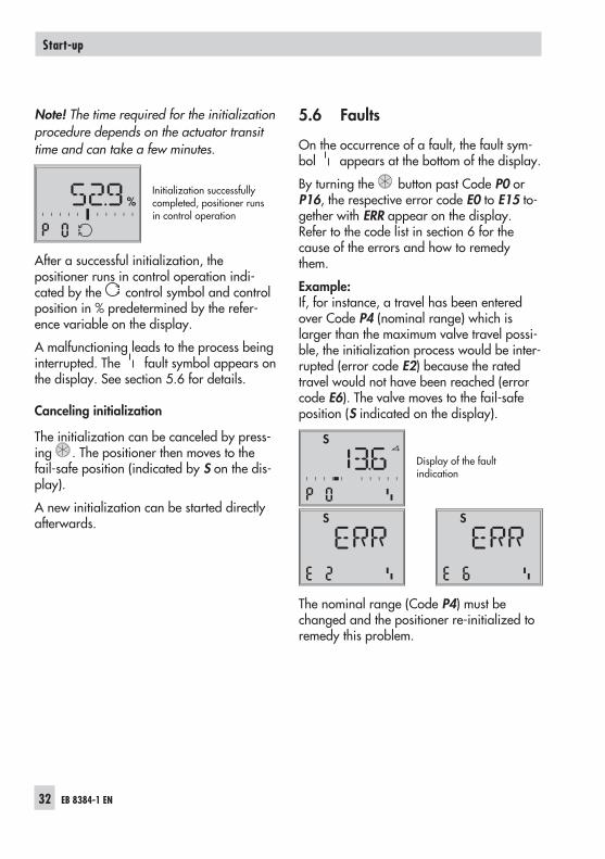
5.6 Faults
On the occurrence of a fault, the fault sym-bol appears at the bottom of the display.
By turning the button past Code P0 orP16, the respective error code E0 to E15 to-gether with ERR appear on the display.Refer to the code list in section 6 for thecause of the errors and how to remedythem.
Example:If, for instance, a travel has been enteredover Code P4 (nominal range) which islarger than the maximum valve travel possi-ble, the initialization process would be inter-rupted (error code E2) because the ratedtravel would not have been reached (errorcode E6). The valve moves to the fail-safeposition (S indicated on the display).
Display of the faultindication
The nominal range (Code P4) must bechanged and the positioner re-initialized toremedy this problem.
32 EB 8384-1 EN
Start-up
S
S S
%
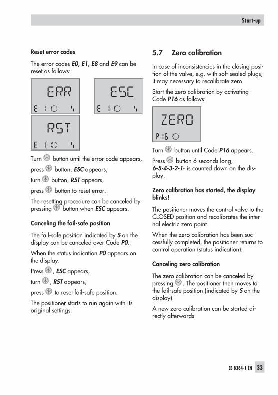
Reset error codes
The error codes E0, E1, E8 and E9 can bereset as follows:
Turn button until the error code appears,
press button, ESC appears,
turn button, RST appears,
press button to reset error.
The resetting procedure can be canceled bypressing button when ESC appears.
Canceling the fail-safe position
The fail-safe position indicated by S on thedisplay can be canceled over Code P0.
When the status indication P0 appears onthe display:
Press , ESC appears,
turn , RST appears,
press to reset fail-safe position.
The positioner starts to run again with itsoriginal settings.
5.7 Zero calibration
In case of inconsistencies in the closing posi-tion of the valve, e.g. with soft-sealed plugs,it may necessary to recalibrate zero.
Start the zero calibration by activatingCode P16 as follows:
Turn button until Code P16 appears.
Press button 6 seconds long,6-5-4-3-2-1- is counted down on the dis-play.
Zero calibration has started, the displayblinks!
The positioner moves the control valve to theCLOSED position and recalibrates the inter-nal electric zero point.
When the zero calibration has been suc-cessfully completed, the positioner returns tocontrol operation (status indication).
Canceling zero calibration
The zero calibration can be canceled bypressing . The positioner then moves tothe fail-safe position (indicated by S on thedisplay).
A new zero calibration can be started di-rectly afterwards.
EB 8384-1 EN 33
Start-up
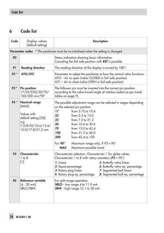
6 Code list
Code Display, values[default setting]
Description
Parameter codes * The positioner must be re-initialized when the setting is changed
P0 Status indication showing basic information.Canceling the fail-safe position with RST is possible.
P1 Reading direction The reading direction of the display is turned by 180°.
P2 * ATO/ATC Parameter to adapt the positioner to how the control valve functions:ATO – Air to open (valve CLOSED in fail-safe position)ATC – Air to close (valve OPEN in fail-safe position)
P3 * Pin position17/25/[35]/50/70/100/200 mm/90°
The follower pin must be inserted into the correct pin positionaccording to the valve travel/angle of rotation (select as per traveltables on page 9).
P4 * Nominal range[MAX]
Values withdefault setting [35]:e.g.7.5/8.92/10.6/12.6/15.0/17.8/21.2 mm
The possible adjustment range can be selected in stages dependingon the selected pin position17 from 3.75 to 10.625 from 5.3 to 15.035 from 7.5 to 21.250 from 10.6 to 30.070 from 15.0 to 42.4100 from 21.2 to 60.0200 from 42.4 to 120
For 90° Maximum range only, if P3 = 90°MAX Maximum possible travel
P5 Characteristic1 to 8[1]
Characteristic selection: Characteristic 1 for globe valves,Characteristic 1 to 8 with rotary actuators (P3 = 90°)1: Linear 5: Butterfly valve linear2: Equal percentage 6: Butterfly valve eq. percentage3: Rotary plug linear 7: Segmented ball linear4: Rotary plug eq. percentage 8: Segmented ball eq. percentage
P6 Reference variable[4...20 mA]SRLO/SRHI
For split-range operationSRLO – low range 4 to 11.9 mASRHI – high range 12.1 to 20 mA
34 EB 8384-1 EN
Code list
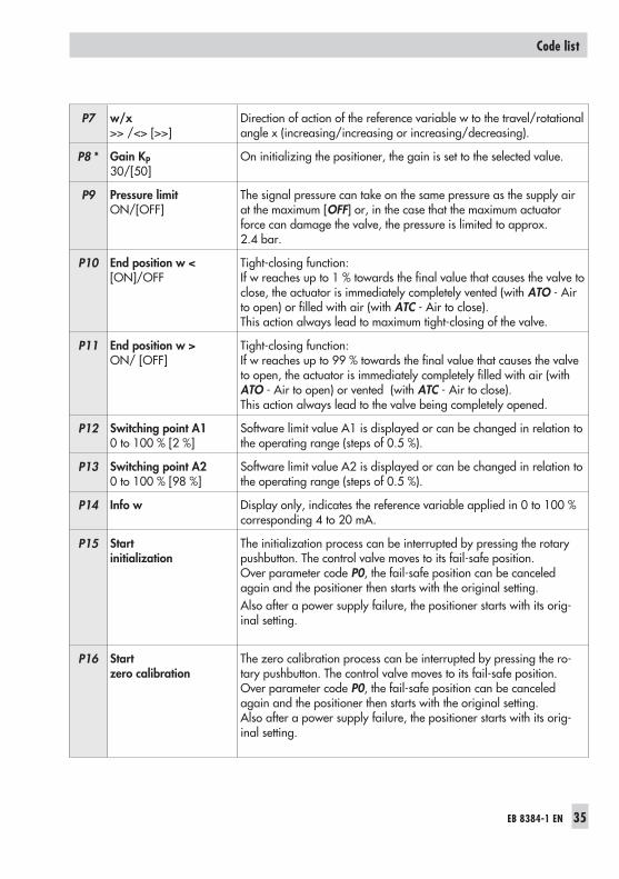
P7 w/x>> /<> [>>]
Direction of action of the reference variable w to the travel/rotationalangle x (increasing/increasing or increasing/decreasing).
P8 * Gain KP30/[50]
On initializing the positioner, the gain is set to the selected value.
P9 Pressure limitON/[OFF]
The signal pressure can take on the same pressure as the supply airat the maximum [OFF] or, in the case that the maximum actuatorforce can damage the valve, the pressure is limited to approx.2.4 bar.
P10 End position w <[ON]/OFF
Tight-closing function:If w reaches up to 1 % towards the final value that causes the valve toclose, the actuator is immediately completely vented (with ATO - Airto open) or filled with air (with ATC - Air to close).This action always lead to maximum tight-closing of the valve.
P11 End position w >ON/ [OFF]
Tight-closing function:If w reaches up to 99 % towards the final value that causes the valveto open, the actuator is immediately completely filled with air (withATO - Air to open) or vented (with ATC - Air to close).This action always lead to the valve being completely opened.
P12 Switching point A10 to 100 % [2 %]
Software limit value A1 is displayed or can be changed in relation tothe operating range (steps of 0.5 %).
P13 Switching point A20 to 100 % [98 %]
Software limit value A2 is displayed or can be changed in relation tothe operating range (steps of 0.5 %).
P14 Info w Display only, indicates the reference variable applied in 0 to 100 %corresponding 4 to 20 mA.
P15 Startinitialization
The initialization process can be interrupted by pressing the rotarypushbutton. The control valve moves to its fail-safe position.Over parameter code P0, the fail-safe position can be canceledagain and the positioner then starts with the original setting.Also after a power supply failure, the positioner starts with its orig-inal setting.
P16 Startzero calibration
The zero calibration process can be interrupted by pressing the ro-tary pushbutton. The control valve moves to its fail-safe position.Over parameter code P0, the fail-safe position can be canceledagain and the positioner then starts with the original setting.Also after a power supply failure, the positioner starts with its orig-inal setting.
EB 8384-1 EN 35
Code list
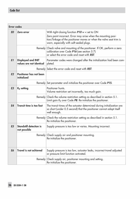
Error codes
E0 Zero error With tight-closing function P10 w < set to ONZero point incorrect. Error may arise when the mounting posi-tion/linkage of the positioner moves or when the valve seat trim isworn, especially with soft-sealed plugs.
Remedy Check valve and mounting of the positioner. If OK, perform a zerocalibration over Code P16 (see section 5.7)or select the error code and reset with RST.
E1 Displayed and INITvalues are not identical
Parameter codes were changed after the initialization had been com-pleted.
Remedy Select the error code and reset with RST.
E2 Positioner has not beeninitialized
Remedy Set parameter and initialize the positioner over Code P15.
E3 KP setting Positioner hunts.Volume restriction set incorrectly, too much gain.
Remedy Check the volume restriction setting as described in section 5.1.Limit gain KP over Code P8. Re-initialize the positioner.
E4 Transit time is too fast The transit times of the actuator determined during initialization areso short (under 0.5 second) that the positioner cannot adapt itselfwell enough.
Remedy Check the volume restriction setting as described in section 5.1.Re-initialize the positioner.
E5 Standstill detection isnot possible
Supply pressure is too low or varies. Mounting incorrect.
Remedy Check supply air and positioner mounting.Re-initialize the positioner.
E6 Travel is not achieved Supply pressure is too low, actuator leaks, incorrect travel adjustedor pressure limit function activated.
Remedy Check supply air, positioner mounting and setting.Re-initialize the positioner.
36 EB 8384-1 EN
Code list
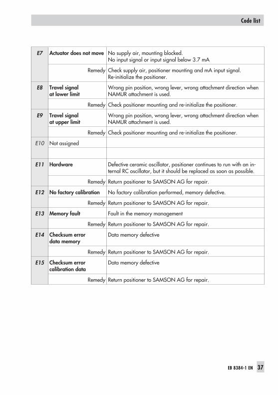
E7 Actuator does not move No supply air, mounting blocked.No input signal or input signal below 3.7 mA
Remedy Check supply air, positioner mounting and mA input signal.Re-initialize the positioner.
E8 Travel signalat lower limit
Wrong pin position, wrong lever, wrong attachment direction whenNAMUR attachment is used.
Remedy Check positioner mounting and re-initialize the positioner.
E9 Travel signalat upper limit
Wrong pin position, wrong lever, wrong attachment direction whenNAMUR attachment is used.
Remedy Check positioner mounting and re-initialize the positioner.
E10 Not assigned
E11 Hardware Defective ceramic oscillator, positioner continues to run with an in-ternal RC oscillator, but it should be replaced as soon as possible.
Remedy Return positioner to SAMSON AG for repair.
E12 No factory calibration No factory calibration performed, memory defective.
Remedy Return positioner to SAMSON AG for repair.
E13 Memory fault Fault in the memory management
Remedy Return positioner to SAMSON AG for repair.
E14 Checksum errordata memory
Data memory defective
Remedy Return positioner to SAMSON AG for repair.
E15 Checksum errorcalibration data
Data memory defective
Remedy Return positioner to SAMSON AG for repair.
EB 8384-1 EN 37
Code list
7 Maintenance
The positioner does not require any mainte-nance.
There are filters with a 100 μm mesh size inthe pneumatic connections for supply andoutput which can be removed and cleaned, ifrequired.
The maintenance instructions of any up-stream supply air pressure reducing stationsmust be observed.
8 Servicing explosion-protecteddevices
If a part of the positioner on which the explo-sion protection is based needs to be serviced,the positioner must not be put back into op-eration until an expert has inspected the de-vice according to explosion protection re-quirements, has issued a certificate statingthis or given the device a mark of conformity.
Inspection by an expert is not required if themanufacturer performs a routine test on thedevice prior to putting it back into operation.The passing of the routine test must be docu-mented by attaching a mark of conformity tothe device.
Devices that have already been used outsideof hazardous areas and are intended for usein hazardous areas in future must complywith the safety demands placed on repaireddevices. Prior to operation, they must betested according to the specifications stipu-lated for "Repairing explosion-protected de-vices".
38 EB 8384-1 EN
Maintenance
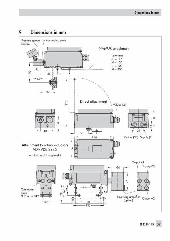
9 Dimensions in mm
EB 8384-1 EN 39
Dimensions in mm
A1 Z
A2
40
34
210
28
1480
164 Output (38) Supply (9)
86
70
15
46
34
Output A1
Output A2
Supply (9)
50 80130
495979
76
50
58
58
58
Attachment to rotary actuatorsVDI/VDE 3845
for all sizes of fixing level 2
or connecting plate
Direct attachment
NAMUR attachment
Pressure gaugebracket
Lever mmS = 17M = 50L = 100XL = 200
ConnectingplateG ¼ or ¼ NPT Reversing amplifier
(option)
M20 x 1.5
40 EB 8384-1 EN
EB 8384-1 EN 41
42 EB 8384-1 EN
EB 8384-1 EN 43
44 EB 8384-1 EN
EB 8384-1 EN 45
�
�������������
�� ������������������������������
������������������������������� �!"���
�
����
����
����
��
����
�����
���
���
� ��
�� �
���
���
��
����
��
����
����
�
���
��
���
��
���
���
���
����
� �
���
���
���
���
���
���
���
���
�����
����
���
���
���
�� �!
��
�"
���
���
����
#��
��
���
�$
��
�%
��
���
����
�#��
��
��� �&�'
�#��
��
����
����
���
�(
���
��
���
�� )
��
�*�
����
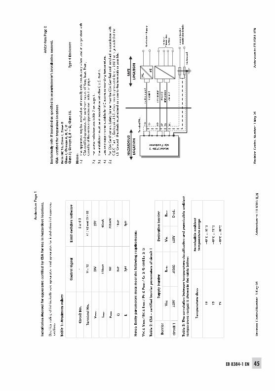
��������� ���������� ��������������� ������� ���������� ������������ �����������������������
������������������ ������������������ ���� ���!�"�
��!�#����
!��
�� �����$�������������� ������ � ���������������%�����
&���
�������� ��������� ���������&�����%�����
'���
������ ������������ �����������������������������(����#������
)���
* ������� ������� � �����������+,�������� �������%�����������
+���
�������������������-��������.������ ������������������������ �������������������������
��(����#�������(����������"������� ��� ������������������ ������������ �%���������������
�"����/���������� �������� ���������� ���� ������������
���� �� �� ������
� �+
�!
�,
%-
.��
������
&��
��/
-�
���-
)�
/-
��
��-
)�
� � � � � � � � � � � � � � � � � � � � � � �
������������
�� ������������
����
� � �����������
����
��� �
����
��� �
���
�� �
�� �����������
���� ���
���� ���� ��
���� ���
���� ���� ��
���� � ��
����
�����
� � �
�����
������������� �
������
����������
��� ���
������������
���������������� �
�
�������������
�� ������������������������������
��������������������������������� !���
�
������������������� ���� ������ ������������� ��������� ��������������
���������
���
���� ��������
�����
�������
�����������
��� �����������������
�����
����
�����
�������������������
����� ���� ���
!�����"����������"� �
�� ����#��
��
���
��
���
�� �
����#��
����
����
���
����
��
�����
��
$����
���
�� �
�
�����
���
��
� �
��
%����
��
�� �
��
�� �
��
��
���
��
!� �
�
��
�
��
� #�����&������� ����� �����������������"�� �'�� �������
$��
�
($
����
) ����
�
(����)%
�(%
���)�
��
�
*�
����!�
�
�
*!� ��
� �����+����,�� �������� �� �� ����� ����� �����
�������� ��
&����������� ��
-� ��
$��
.���
$��
.���
�� �����
����
��� �
�����
��
���
��
� �����/������ ����������"�������� ��� �������������������� �
��������������
����� ��� � �� �������"���������������"�
����� ��� ������
%� �
��������������
����� ��� � �� �
���
��
��
�� ��
� �
��
�
�� ��
� �!
��
�
�� ��
� ��
��
�
� � � � � �
46 EB 8384-1 EN
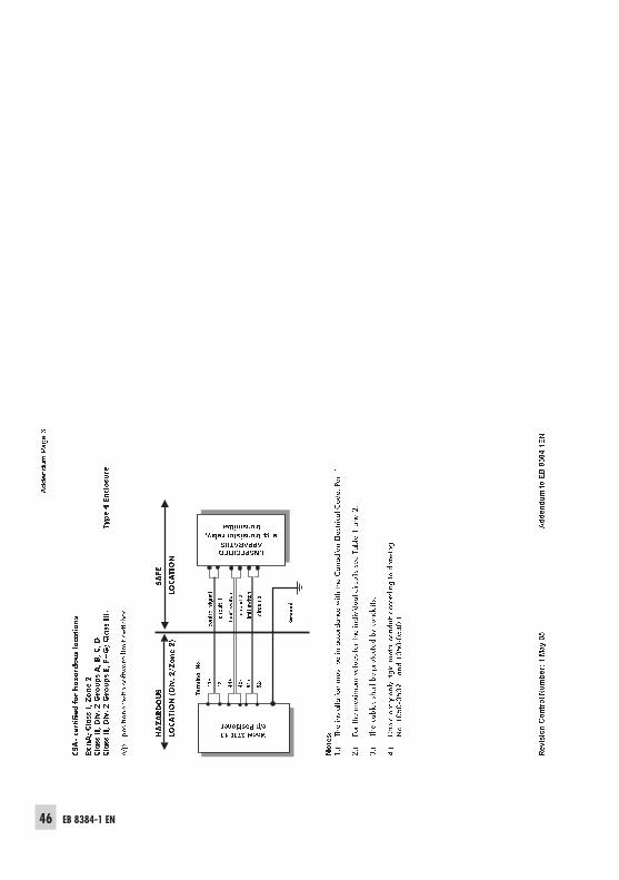
�
�������������
�� ������������������������������
��������������������������������� !���
�
� ������������� �������� ���� �� ���
����������������� �����
������������������ � �����!�������
������������������ � �����"#��������������
$% ��&����� �����
� ���
�������������� ��������
����
������
����
� � � �'���(�)*��
���"��
�+)��$�),�-�����.� ����/�
+)��$�),�
, ��0�
����
� ��������
����
��������������
���
��� � ���
��������������
��������������
� ����
���� ���
� �����!���������� �����!����������������
����������������
� "���
� ����������
����������
������#���
������
� $���
��������#���#���%����
������
����������
�%������
��%��
�&����'('�'
(")�������'('�'
($'���
������������
�� ������������
����
��� �
����
����
����
����
��� ����� �
����������
������������
����������
������������
����������
����������
�����
������������
����������
������������������ ��
����������

EB 8384-1 EN 47

SAMSON AG · MESS- UND REGELTECHNIKWeismüllerstraße 3 · 60314 Frankfurt am Main · GermanyPhone: +49 69 4009-0 · Fax: +49 69 4009-1507Internet: http://www.samson.de EB 8384-1 EN S/
Z20
06-0
5


