HAL Id: inserm-00130038 https://www.hal.inserm.fr/inserm-00130038 Submitted on 5 Apr 2007 HAL is a multi-disciplinary open access archive for the deposit and dissemination of sci- entific research documents, whether they are pub- lished or not. The documents may come from teaching and research institutions in France or abroad, or from public or private research centers. L’archive ouverte pluridisciplinaire HAL, est destinée au dépôt et à la diffusion de documents scientifiques de niveau recherche, publiés ou non, émanant des établissements d’enseignement et de recherche français ou étrangers, des laboratoires publics ou privés. MSCT labelling for pre-operative planning in cardiac resynchronization therapy. Kristell Rioual, Edurne Unanua, Soizic Laguitton, Mireille Garreau, Dominique Boulmier, Pascal Haigron, Christophe Leclercq, Jean-Louis Coatrieux To cite this version: Kristell Rioual, Edurne Unanua, Soizic Laguitton, Mireille Garreau, Dominique Boulmier, et al.. MSCT labelling for pre-operative planning in cardiac resynchronization therapy.. Computerized Med- ical Imaging and Graphics, Elsevier, 2005, 29 (6), pp.431-9. 10.1016/j.compmedimag.2005.04.005. inserm-00130038
Transcript
HAL Id: inserm-00130038https://www.hal.inserm.fr/inserm-00130038
Submitted on 5 Apr 2007
HAL is a multi-disciplinary open accessarchive for the deposit and dissemination of sci-entific research documents, whether they are pub-lished or not. The documents may come fromteaching and research institutions in France orabroad, or from public or private research centers.
L’archive ouverte pluridisciplinaire HAL, estdestinée au dépôt et à la diffusion de documentsscientifiques de niveau recherche, publiés ou non,émanant des établissements d’enseignement et derecherche français ou étrangers, des laboratoirespublics ou privés.
MSCT labelling for pre-operative planning in cardiacresynchronization therapy.
Pascal Haigrona, Christophe Leclercqb, Jean-Louis Coatrieuxa aLaboratoire Traitement du Signal et de l’Image,INSERM U642, Université de Rennes 1, 35042 Rennes, France.
bCentre Cardio-Pneumologique, CHU Pontchaillou, 35033 Rennes, France.
Corresponding author : Jean-Louis COATRIEUX
Mailing Address : Laboratoire Traitement du Signal et de l’Image,
• acquire and represent the specific physiological knowledge necessary to choose
the most appropriate CRT for a given patient.
• define new methods for automatic navigation on 3D volumes in a dynamic
environment, so as to define an access path to the optimal pacing site and
propose an electrophysiological exploration protocol.
• model the pacemaker behaviour and to couple it with the cardiac model.
• propose a way to assist operator-based navigation by coupling pre- and intra-
operative images (or volumes).
• model the pacemaker behaviour and to couple it with the cardiac model so as
to simulate the hemodynamic benefit of biventricular pacing, with respect to
the pacing site and to propose patient-specific solutions.
7. Summary
HA
L author manuscript inserm
-00130038, version 1
- 12 -
It has been shown throughout this paper that MSCT data sets offer a major contribution for
preparing interventions dealing with Cardiac Resynchronization Therapy. They provide in
depth insights into the main structures as well as the critical veins of concern. The complexity
of the scene, due to the many entities that it contains, the complicated shapes and the inter-
individual variations that may be observed, requires previous visual exploration and labelling,
advanced image processing tools and efficient 3-D rendering techniques. These new
resources, however, open the road to multiple research developments that can be of major
importance to reduce the time of intervention, to make the procedure safer for the patient and
finally to improve the success rate of CRT.
Acknowledgements
The authors are indebted to B. Le Bruno, from Siemens Medical Division, France, for her
constant support during the collection of MSCT data sets.
HA
L author manuscript inserm
-00130038, version 1
- 13 -
Appendix
Schematically, this new procedure begins with placement of a coronary sinus (CS)
catheter. A long sheath is then passed over this catheter and placed in the CS. The CS catheter
is removed and a balloon-tipped catheter is inserted via the sheath into the CS. The balloon is
inflated, contrast is injected and a CS venogram is made in both the right and left anterior
oblique views. Using both views allows identification of possible target sites for the
permanent pacing lead. The usual site chosen is a lateral coronary vein about midway between
the apex and the base. Next, the balloon catheter is removed and the pacing lead is introduced
through the sheath (soft tines at the tip of the lead enable successful passive fixation in the
coronary sinus). It is manipulated into the target site and pacing measurements are made
(threshold, R wave, slew rate, and impedance). If satisfactory, the lead is left in place. The
optimal site for left ventricular pacing is in the lateral or posterolateral cardiac vein. This is
because pacing from the mid lateral wall or posterior wall results in the best percentage
increase in pulse pressure and left ventricular dP/dt. However, at times, they are too small for
the lead to enter or do not result in a stable position and the lead is then positioned in the
anterior great cardiac vein [22].
Once the left ventricular lead is secured, the right ventricular apex lead and right atrial
lead are then implanted in the usual manner for a dual chamber pacemaker. Where possible,
the RV and LV lead should however be anatomically as far apart as possible, so as to obtain
maximal separation between the right and the left ventricular lead tip in both AP and LAO
views. In patients with left ventricular leads in the great cardiac vein, or in the lateral or
postero-lateral branches of the CS a mid-inferior wall position is chosen for the right
ventricular lead. In those with a posterior or mi-cardiac vein position, the right ventricular
lead is positioned in the right ventricular outflow tract or on the right ventricular septum. The
right atrial leads are routinely positioned in the right atrial appendage [23].
HA
L author manuscript inserm
-00130038, version 1
- 14 -
References
[1] Cazeau S, Leclercq C, Lavergne T et al. Effects of multisite biventricular pacing in patients with heart failure and intraventricular delay, New England Journal of Medicine 2001;344:873-880.
[2] Leclercq C, Kass DA. Re-timing the failing heart: principles and current clinical status of cardiac resynchronization. Journal of the American College of Cardiology 2002;39:194-201.
[3] Kass DA. Predicting cardiac resynchronization response by GRS duration. Journal of the American College of Cardiology 2003;42:2125-2127.
[4] Gepstein L, Hayan G, Ben-Haim SA. A novel method for nonfluoroscopic catheter-based electroanatomical mapping of the heart: in vitro and in vivo accuracy results. Circulation 1997;95:1611-1622.
[5] Schilling RJ, Peters S, Davies DW. Simultaneous endocardial mapping in the left ventricle using a noncontact catheter: comparison of contact and reconstructed electrograms during sinus rhythm. Circulation 1998;98:887-898.
[6] De Bakker JMT, Hauer RNW, Simmens TA. Activation mapping: unipolar versus bipolar recording, In: Zipes D.P, Jalife J Eds, Cardiac Electrophysioloy: from cell to bedsite. 3rd ed. Philadelphia:Saunders, 2000:1068-1078.
[7] DeRose J.J, Ashton R.C, Belsey S et al. Robotically assisted left ventricular epicardial lead implantation for biventricular pacing. Journal of the American College of Cardiology 2003 ;41:1414-1419.
[8] Daubert J, Pitter P, Le Breton H, Gras D, Leclercq C, Lazarus A, Mugica J, Mabo P, Cazeau S. Permanent left ventricular pacing with transvenous leads inserted into the coronary veins. PACE 1998 ;21: 239-245.
[9] Abraham WT. Rationale and design of a randomized clinical trial to assess the safety and efficacy of cardiac resynchronization therapy in patients with advanced heart failure: the Multicenter InSync Randomized Clinical Evaluation (MIRACLE). Journal of Cardiac Failure 2000;6:369-380.
[10] Alonzo C, Leclercq C, d’Allones F.R et al. Six years experience of transvenous left ventricular lead implantation for permanent biventricular pacing in patients with advanced heart failure: technical aspects. Heart 2001;86:405-410.
[11] Cazeau S, Leclercq C, Lavergne T, et al. Effects of multisite biventricular pacing in patients with heart failure and intraventricular conduction delay. The Multisite Stimulation in Cardiomyopathies (MUSTIC) Study Investigators. New England Journal of Medicine 2001;344:873-880.
[12] Abraham WT, Fisher WG, Smith AL, et al, for the MIRACLE Study Group. Cardiac Resynchronization in chronic heart failure. New England Journal of Medicine 2002; 346:1845-1853.
[13] Taylor RH, Lavallée S, Burdea GC, Mösges R. Computer-Integrated Surgery, Technology and Clinical Applications. Cambridge: MIT press, 1996.
[14] Roux C, Coatrieux JL. Contemporary perspectives on Three Dimensional Biomedical Imaging. Amsterdam:IOS Press,1997.
[16] Haigron P, Bellemare ME, Acosta O, Goksu C, Kulik C, Rioual K, Lucas A. Depth-Map-Based Scene Analysis for Active Navigation in Virtual Endoscopy. IEEE Transactions on Medical Imaging 2004;23(11):1380-1390.
HA
L author manuscript inserm
-00130038, version 1
- 15 -
[17] Bellemare ME, Haigron P, Coatrieux JL. Toward an active three dimensional navigation system in medical imaging. Proceedings of Computer Vision, Virtual Reality, and Robotics in Medicine and Medical Robotics and Computer Assisted Surgery. Grenoble (France): Springer LNCS 1205, 1997:337-346.
[18] Coatrieux JL. Les bases scientifiques de l’endoscopie virtuelle. Bulletin de l’Académie Nationale de Médecine 1999;183(3):455-464.
[19] Acosta O, Moisan C, Haigron P, Lucas A (2004). Evaluation of Virtual Exploratory Navigation for the Characterization of Stenosis in the Planning of Endovascular Interventions. In: Clough AV, Chen CT, editors. Proceedings of SPIE Medical Imaging. San Diego (California, USA): SPIE 2002;4683:42-53.
[20] Haigron P, Le Berre G, Coatrieux JL. 3-D navigation in medicine. IEEE Engineering in Medicine and Biology 1996;15(2):70-78.
[21] Larralde A, Boldak C, Garreau M, Toumoulin C, Boulmier D, Rolland Y. Evaluation of a 3D Segmentation Software for the Coronary Characterization in Multi-slice Computed Tomography. Proceedings of Functional Imaging and Modeling of the Heart. Lyon(France): Springer LNCS 3674, 2003:39-51.
[22] Teo WS, Kam R, Hsu LF. Treatment of Heart Failure - Role of Biventricular Pacing for Heart Failure Not Responding Well to Drug Therapy. Singapore Medical Journal 2003;44(3): 114-122.
[23] Walker S, Levy T, Rex S, Brant S, Paul V. Initial United Kingdom experience with the use of permanent, biventricular pacemakers: Implantation procedure and technical considerations. Europace 2000;2(3):233-239.
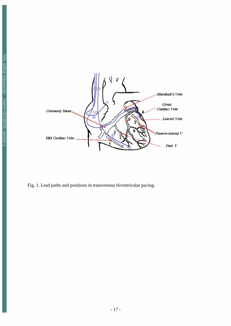
Fig. 1. Lead paths and positions in transvenous biventricular pacing. Fig.2. Labelling of heart structures in MSCT data. The dataset was acquired at 30% of the cardiac cycle. The subset of slices is composed of 12 labelled slices. The slices, selected to show different anatomical features, are numbered at the top left corner. The level window is between -100 HU and 700 HU. The letters A, P, R and L, that denote respectively anterior, posterior, right and left, are used to indicate the slice position relative to the patient’s body. Fig.3. Virtual fly-through the heart venous structures. The sequence is composed of images selected at four different locations (a: inside the right atrium, close to the coronary sinus, b:at the coronary sinus entrance, c:inside the great vein, and d: inside the lateral vein). For each location, the left part shows the virtual navigation view and the right part shows an arrow representing the pose of the virtual endoscope in the volume image and superimposed on three orthogonal MSCT slices. The location of the MSCT slices corresponds to the origin of the arrow, whereas the viewing axis of the virtual endoscope is represented by the orientation of the arrow.
HA
L author manuscript inserm
-00130038, version 1
- 17 -
Fig. 1. Lead paths and positions in transvenous biventricular pacing.
HA
L author manuscript inserm
-00130038, version 1
- 18 -
Great vein
Great vein
Left ant pulm veinLeft post pulm vein
pulmonary
Pulmonaryvalve
Ascendingaorta
Superiorvena cava Right
artery Left
artery
Pulmonarytrunk
pulmonary
pulmonary
Descendingaorta
Right coronary
Right ventricule
Circumflex
Inter ventricularartery
Great vein
Diagonal
Great vein
Rightatrium
Superiorvena cava
Great vein
Great vein
Lat circumflexartery
Superiorvena cava
Circumflex
Great vein
Great vein
Left ant pulm veinLeft post pulm vein
Great vein
Great vein
Left ant pulm veinLeft post pulm vein
pulmonary
Pulmonaryvalve
Ascendingaorta
Superiorvena cava Right
artery Left
artery
Pulmonarytrunk
pulmonary
pulmonary
Descendingaorta
pulmonary
Pulmonaryvalve
Ascendingaorta
Superiorvena cava Right
artery Left
artery
Pulmonarytrunk
pulmonary
pulmonary
Descendingaorta
Right coronary
Right ventricule
Circumflex
Inter ventricularartery
Great vein
Diagonal
Great vein
Rightatrium
Superiorvena cava
Right coronary
Right ventricule
Circumflex
Inter ventricularartery
Great vein
Diagonal
Great vein
Rightatrium
Superiorvena cava
Great vein
Great vein
Lat circumflexartery
Superiorvena cava
CircumflexGreat vein
Great vein
Lat circumflexartery
Superiorvena cava
Circumflex
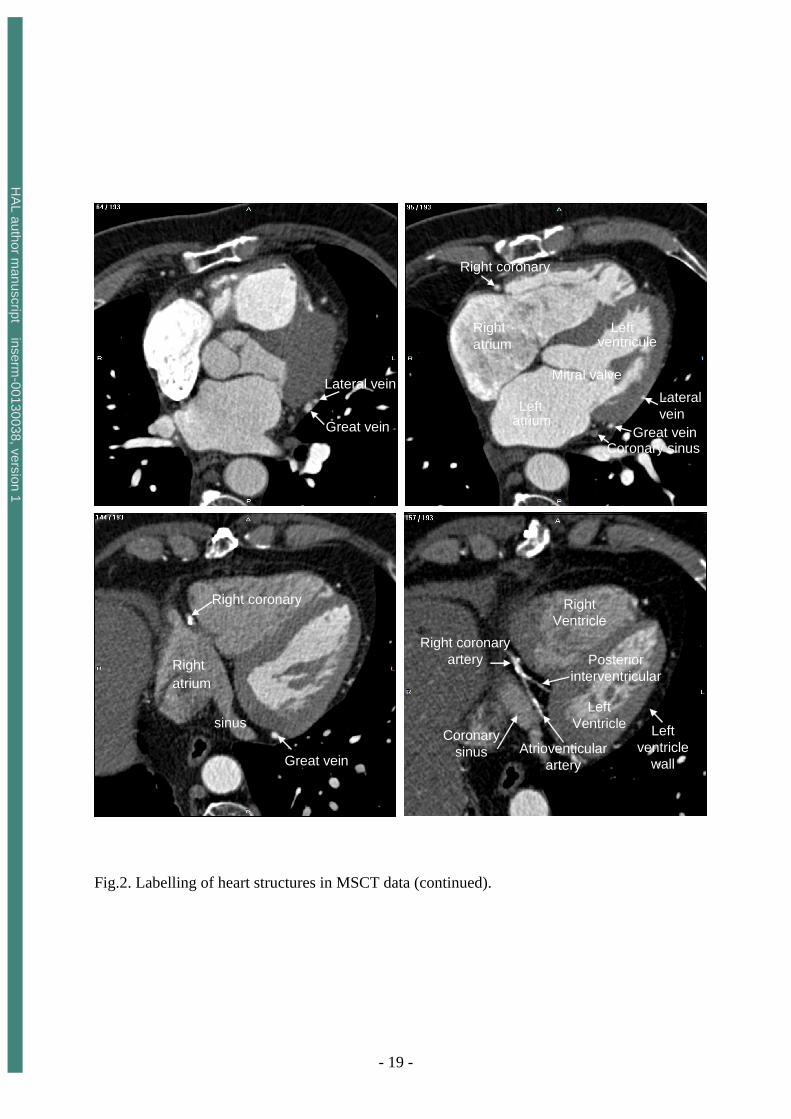
Fig.2. Labelling of heart structures in MSCT data. The dataset was acquired at 30% of the cardiac cycle. The subset of slices is composed of 12 labelled slices. The slices, selected to show different anatomical features, are numbered at the top left corner. The level window is between -100 HU and 700 HU. The letters A, P, R and L, that denote respectively anterior, posterior, right and left, are used to indicate the slice position relative to the patient’s body.
HA
L author manuscript inserm
-00130038, version 1
- 19 -
Lateral vein
Great vein
Right coronary
Right atrium
Mitral valve
Leftventricule
Leftatrium
Lateralvein
Great veinCoronary sinus
Right coronary
sinus
Rightatrium
Great vein
Posteriorinterventricular
Right coronaryartery
Coronarysinus
Right Ventricle
LeftVentricle Left
ventriclewall
Atrioventicularartery
Lateral vein
Great vein
Lateral vein
Great vein
Right coronary
Right atrium
Mitral valve
Leftventricule
Leftatrium
Lateralvein
Great veinCoronary sinus
Right coronary
Right atrium
Mitral valve
Leftventricule
Leftatrium
Lateralvein
Great veinCoronary sinus
Right coronary
sinus
Rightatrium
Great vein
Right coronary
sinus
Rightatrium
Great vein
Posteriorinterventricular
Right coronaryartery
Coronarysinus
Right Ventricle
LeftVentricle Left
ventriclewall
Atrioventicularartery
Posteriorinterventricular
Right coronaryartery
Coronarysinus
Right Ventricle
LeftVentricle Left
ventriclewall
Atrioventicularartery
Fig.2. Labelling of heart structures in MSCT data (continued).
HA
L author manuscript inserm
-00130038, version 1
- 20 -
Posterior vein
sinus
Postero lateral vein 1
Middle vein
Posterior vein
Postero-lateral vein 2
Postero-lateral vein 1
Posterior vein
sinus
Posterior vein
sinus
Postero lateral vein 1Postero lateral vein 1
Middle vein
Posterior vein
Middle vein
Posterior vein
Postero-lateral vein 2
Postero-lateral vein 1
Postero-lateral vein 2
Postero-lateral vein 1
Fig.2. Labelling of heart structures in MSCT data (continued).
HA
L author manuscript inserm
-00130038, version 1
- 21 -
(a)
(b)
(c)
(d)
(a)
(b)
(c)
(d)
Fig.3. Virtual fly-through the heart venous structures. The sequence is composed of images selected at four different locations (a: inside the right atrium, close to the coronary sinus, b:at the coronary sinus entrance, c:inside the great vein, and d: inside the lateral vein). For each location, the left part shows the virtual navigation view and the right part shows an arrow representing the pose of the virtual endoscope in the volume image and superimposed on three orthogonal MSCT slices. The location of the MSCT slices corresponds to the origin of the arrow, whereas the viewing axis of the virtual endoscope is represented by the orientation of the arrow.