Page 1
N E T W O R K S U P E R V I S I O N
© 2003 Fluke Networks1 ISV Workshop 2003 - Rev 0.0
Twisted-Pair Copper CablingTwisted-Pair Copper Cabling
Industry Standards Review
Testing Permanent link, Patch Cords and Channel Links
+ Reporting and Documentation
Page 2
N E T W O R K S U P E R V I S I O N
© 2003 Fluke Networks2 ISV Workshop 2003 - Rev 0.0
The StandardsThe Standards
Overview: TSB67 to TIA568-B
Test Configurations / Link Models
Permanent Link Replaces Basic Link
Page 3
N E T W O R K S U P E R V I S I O N
© 2003 Fluke Networks3 ISV Workshop 2003 - Rev 0.0
Cabling Standards Around the World
ISO/IEC 11801:2002IT Generic Cabling for Customer
Premises
ANSI/TIA/EIA 568-BCommercial BuildingTelecommunications Wiring Standard
EN50173:2002Performance Requirements OfGeneric Cabling Systems
Page 4
N E T W O R K S U P E R V I S I O N
© 2003 Fluke Networks4 ISV Workshop 2003 - Rev 0.0
Cabling Certification & Maintenance
Primary functions of Cabling Test Equipment Certify & Document for proof of performance to Industry
Standards. US, European or other Region specifications for
structured cabling standards IEEE physical media performance requirements for
specified data rate & Bit Error Rate. Maintenance/Service
Moves, Adds, Changes and troubleshooting
Page 5
N E T W O R K S U P E R V I S I O N
© 2003 Fluke Networks5 ISV Workshop 2003 - Rev 0.0
Signal
Transmit
Receive
WorkstationWorkstation
Transmit
Receive
LANLANEquipmentEquipmentSignal
The Traditional Two Wire-Pair System
The basis for the Cat 5 testing philosophy
Page 6
N E T W O R K S U P E R V I S I O N
© 2003 Fluke Networks6 ISV Workshop 2003 - Rev 0.0
NEXTSignal-to-noise ratio: Attenuation to Crosstalk Ratio (ACR)
SignalAttenuated Signal
Transmit
Receive
WorkstationWorkstation
Transmit
Receive
LANLANEquipmentEquipmentSignal
The category 5 “system” Signal strength: measured by “Attenuation” Noise: Near-End Cross Talk (NEXT)
Page 7
N E T W O R K S U P E R V I S I O N
© 2003 Fluke Networks7 ISV Workshop 2003 - Rev 0.0
Legacy Field Test Parameters TSB-67
Transmission Performance Specifications Wire Map Length
Propagation Delay Delay Skew
Attenuation Near-End Crosstalk (NEXT)
Page 8
N E T W O R K S U P E R V I S I O N
© 2003 Fluke Networks8 ISV Workshop 2003 - Rev 0.0
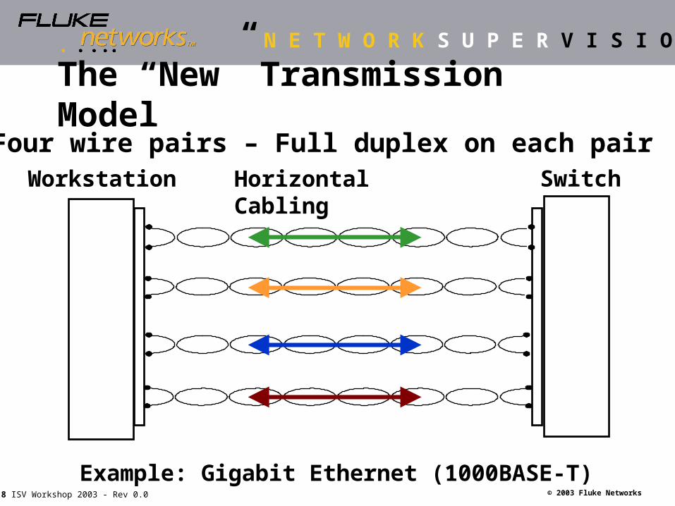
Horizontal CablingWorkstation Switch
Four wire pairs – Full duplex on each pair
Example: Gigabit Ethernet (1000BASE-T)
The “New” Transmission Model
Page 9
N E T W O R K S U P E R V I S I O N
© 2003 Fluke Networks9 ISV Workshop 2003 - Rev 0.0
Multiple Pair Transmission
Workstation LAN Hub
Transmit(Output)
Transmit(Output)
ReceiveInput
Receive(Input)
Signal 2
Signal 1
Example: 1000BASE-T: (4 pairs are used.)
Attenuation (signal loss) and FEXT (internal noise) are the key measurement parameters
FEXT
Page 10
N E T W O R K S U P E R V I S I O N
© 2003 Fluke Networks10 ISV Workshop 2003 - Rev 0.0
Attenuation
Affects of all 3 disturbing pairs = Power Sum
Signal
Power Sum ELFEXT
FEXTPSELFEXT
ELFEXT(signaldifferencein dB)
Page 11
N E T W O R K S U P E R V I S I O N
© 2003 Fluke Networks11 ISV Workshop 2003 - Rev 0.0
Signal A to B
Signal B to A
Return Loss adds disturbance
Desired signal = attenuated signal from other end.Noise = reflected signal on same wire pair.
Full Duplex Transmission
System B
Receive
Transmit
System A
Transmit
Receive Directional Coupler
Page 12
N E T W O R K S U P E R V I S I O N
© 2003 Fluke Networks12 ISV Workshop 2003 - Rev 0.0
Cat 5e and Cat 6 Test Parameters
Measured CalculatedWire mapPropagation delay Length, Delay SkewAttenuationNEXT (pair-to-pair) PSNEXT, ACR, PSACRFEXT (pair-to-pair) ELFEXT, PSELFEXTReturn Loss
Cat 5e is specified and tested from 1 to 100 MHzCat 6 is specified and tested from 1 to 250 MHz
Page 13
N E T W O R K S U P E R V I S I O N
© 2003 Fluke Networks13 ISV Workshop 2003 - Rev 0.0
TIA/EIA TSB67 TIA/EIA TSB72 TIA/EIA TSB75 TIA/EIA TSB95 ANSI/TIA/EIA‑568‑A‑1 ANSI/TIA/EIA‑568‑A‑2 ANSI/TIA/EIA‑568‑A‑3 ANSI/TIA/EIA‑568‑A‑4 ANSI/TIA/EIA‑568‑A‑5 TIA/EIA/IS‑729
Main DocumentSystem Design specification
Copper – Components
Fiber – Components
568-B.1
568-B.2
568-B.3
ANSI/TIA/EIA-568-B
Approved March 2001
Page 14
N E T W O R K S U P E R V I S I O N
© 2003 Fluke Networks14 ISV Workshop 2003 - Rev 0.0
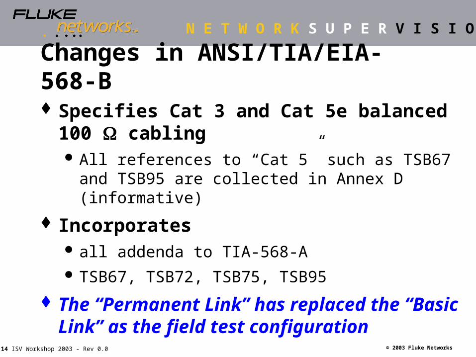
Changes in ANSI/TIA/EIA-568-B
Specifies Cat 3 and Cat 5e balanced 100 cabling All references to “Cat 5” such as TSB67 and TSB95
are collected in Annex D (informative)
Incorporates all addenda to TIA-568-A TSB67, TSB72, TSB75, TSB95
The “Permanent Link” has replaced the “Basic Link” as the field test configuration
Page 15
N E T W O R K S U P E R V I S I O N
© 2003 Fluke Networks15 ISV Workshop 2003 - Rev 0.0
Category 6 Standard
TIA/EIA-568-B.2-1 (Addendum 1) approved June 2002 The last challenge: Fine tune the performance
specification of the Cat 6 connecting hardware Component measurement methodology Plug characterization: amplitude and phase specification of NEXT
disturbance signals
Fluke Networks has actively contributed to standards R&D efforts
Goal: achieve interoperability (as well as backwards compatibility)
Page 16
N E T W O R K S U P E R V I S I O N
© 2003 Fluke Networks16 ISV Workshop 2003 - Rev 0.0
Connecting Hardware NEXT Performance
Cat 6 8-pin Modular Plug
Cat 6 8-pin Modular Jack
Desired Mated NEXT performance for Cat 6
Cat 6 Mated Connection
Better
The standard leads to “Interoperability”
Page 17
N E T W O R K S U P E R V I S I O N
© 2003 Fluke Networks17 ISV Workshop 2003 - Rev 0.0
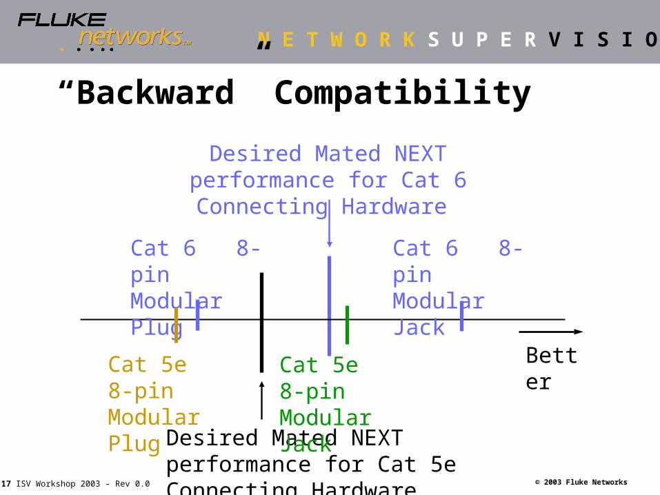
“Backward” Compatibility
Cat 6 8-pin Modular Plug
Cat 6 8-pin Modular Jack
Desired Mated NEXT performance for Cat 6 Connecting Hardware
Cat 5e 8-pin Modular Plug
Desired Mated NEXT performance for Cat 5e Connecting Hardware
Cat 5e 8-pin Modular Jack
Better
Page 18
N E T W O R K S U P E R V I S I O N
© 2003 Fluke Networks18 ISV Workshop 2003 - Rev 0.0
Field Test ProceduresField Test Procedures
“Test Model” options
Importance of Tester Adapter
Ensure link readiness for applications
Page 19
N E T W O R K S U P E R V I S I O N
© 2003 Fluke Networks19 ISV Workshop 2003 - Rev 0.0
HUB or SWITCH
PATCHCORD
Cross-connectPanel
HORIZONTAL CABLE
TO
PATCHCORD
WORKSTATION
TELECOMMUNICATIONSROOM
WORK AREA
An installed “Cabling Link”
CP *
* Consolidation Point (Optional)
Page 20
N E T W O R K S U P E R V I S I O N
© 2003 Fluke Networks20 ISV Workshop 2003 - Rev 0.0
PATCHCORD
Cross-connectPanel
HORIZONTAL CABLE
TO
PATCHCORD
WORKSTATION
TELECOMMUNICATIONSROOM
WORK AREA
Testing the “Channel”
CP *
* Consolidation Point (Optional)
Page 21
N E T W O R K S U P E R V I S I O N
© 2003 Fluke Networks21 ISV Workshop 2003 - Rev 0.0
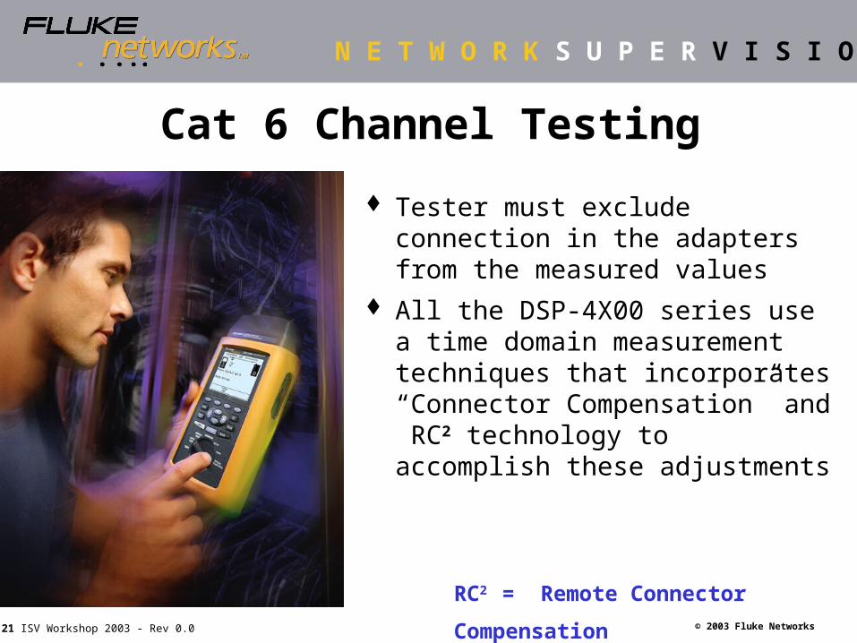
Cat 6 Channel Testing
Tester must exclude connection in the adapters from the measured values
All the DSP-4X00 series use a time domain measurement techniques that incorporates “Connector Compensation” and RC2 technology to accomplish these adjustments
RC2 = Remote Connector Compensation
Page 22
N E T W O R K S U P E R V I S I O N
© 2003 Fluke Networks22 ISV Workshop 2003 - Rev 0.0
TESTER PATCHCABLE
HORIZONTAL CABLE
TO
TESTER PATCHCABLE
WORK AREA
Testing the “Permanent Link”
CP *
* Consolidation Point (Optional)
Test results do not include contributions by the tester patch cables
Page 23
N E T W O R K S U P E R V I S I O N
© 2003 Fluke Networks23 ISV Workshop 2003 - Rev 0.0
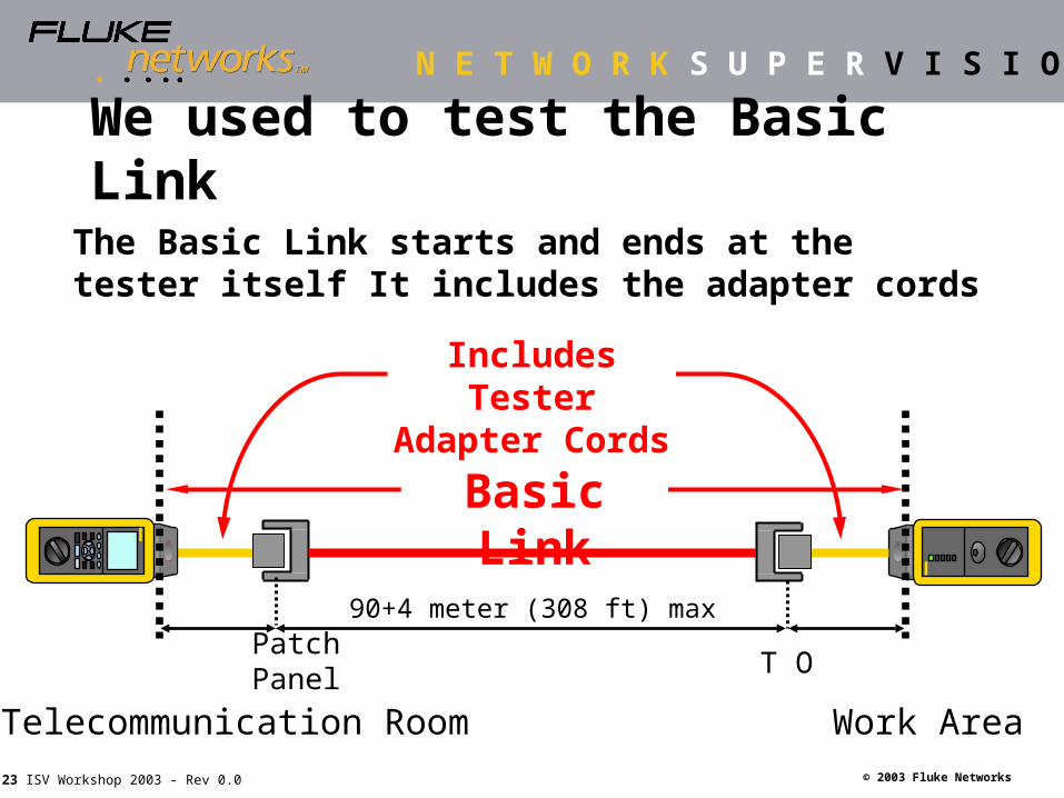
We used to test the Basic Link
The Basic Link starts and ends at the tester itself It includes the adapter cords
Telecommunication Room Work Area
Includes Tester Adapter Cords
Basic Link
Patch Panel T O
90+4 meter (308 ft) max
Page 24
N E T W O R K S U P E R V I S I O N
© 2003 Fluke Networks24 ISV Workshop 2003 - Rev 0.0
The Basic Link is Obsolete
The Permanent Link model replaces the Basic Link in all the standards
Telecommunication Room Work Area
Includes Tester Adapter Cords
Basic Link
Patch Panel T O
90+4 meter (308 ft) max
Page 25
N E T W O R K S U P E R V I S I O N
© 2003 Fluke Networks25 ISV Workshop 2003 - Rev 0.0
A detailed look at the Permanent Link
The Permanent portion of the cabling linkit does not include the adapter cords
Does NOT include Tester Adapter Cords
Permanent Link
Consolidation Point
(optional)Telecommunication Room Work Area
Patch Panel T O
Page 26
N E T W O R K S U P E R V I S I O N
© 2003 Fluke Networks26 ISV Workshop 2003 - Rev 0.0
Why the “permanent link”? The true “foundation” – cabling that is
permanent and part of building infrastructure
Network equipment, patch cables and equipment cables are changed many times during the life of the the cabling infrastructure
Provide guarantee that the ‘Channel’ (permanent link plus patch cables) meets the network application requirements
Page 27
N E T W O R K S U P E R V I S I O N
© 2003 Fluke Networks27 ISV Workshop 2003 - Rev 0.0
Difference in Performance Specification Test limits for the Permanent Link are
defined such that adding “good” patch and equipment cords yield the channel performance
Patch cords’ effect on channel performance: The mating performance of connecting hardware
(primarily NEXT) The performance of patch and equipment cords:
Attenuation (max. 10 meters) Return Loss
Page 28
N E T W O R K S U P E R V I S I O N
© 2003 Fluke Networks28 ISV Workshop 2003 - Rev 0.0
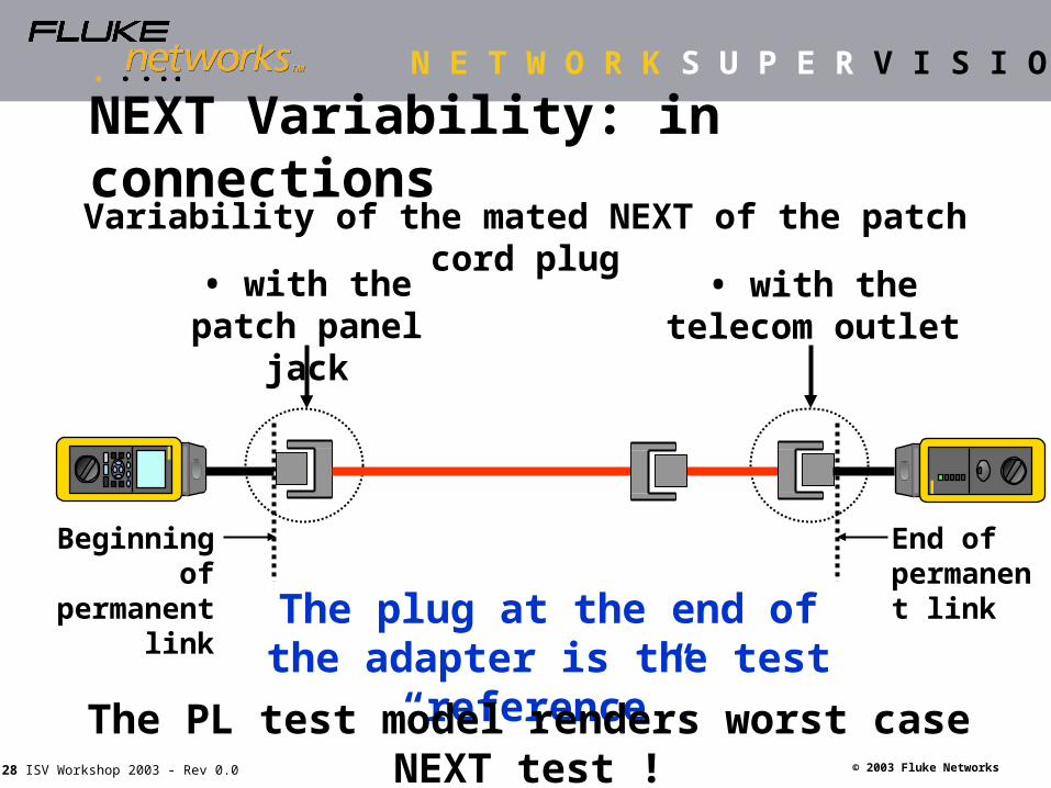
The plug at the end of the adapter is the test “reference”.
• with the patch panel jack
• with the telecom outlet
End of permanent link
Beginning of permanent
link
The PL test model renders worst case NEXT test !
NEXT Variability: in connections Variability of the mated NEXT of the patch cord plug
Page 29
N E T W O R K S U P E R V I S I O N
© 2003 Fluke Networks29 ISV Workshop 2003 - Rev 0.0
The Fluke Networks Solution:The Permanent Link Adapter
A rugged, high-performance link interface adapter for the DSP-4X00 and OMNIScanner2
Very accurately measures the performance of an installed twisted-pair cabling system
Page 30
N E T W O R K S U P E R V I S I O N
© 2003 Fluke Networks30 ISV Workshop 2003 - Rev 0.0
PLA Solution for NEXT Implement the solution to test the Permanent Link
You need only one set of interface adapters and a few sets of Personality Modules
The removable 8-pin plug can be replaced with different “Personality Modules”
Page 31
N E T W O R K S U P E R V I S I O N
© 2003 Fluke Networks31 ISV Workshop 2003 - Rev 0.0
Cat 6 “center definition” for all wire pairs Universal solution
shielded plug to test UTP and ScTP systems
Limit the variability between PMs Increase repeatability (perceived accuracy) Provides optimum result with compliant jack
Page 32
N E T W O R K S U P E R V I S I O N
© 2003 Fluke Networks32 ISV Workshop 2003 - Rev 0.0
A revolutionary plug design
Implemented without cable termination and variability
Favorite of installer: Snag-free clip
Page 33
N E T W O R K S U P E R V I S I O N
© 2003 Fluke Networks33 ISV Workshop 2003 - Rev 0.0
at the beginning at the end
Patch cable has significant impact on Return loss!
This variability is avoided with the permanent link!
Return Loss Variability: Patch cable!
End of permanent link
Beginning of permanent
link
Variability from the patch cable
Page 34
N E T W O R K S U P E R V I S I O N
© 2003 Fluke Networks34 ISV Workshop 2003 - Rev 0.0
The (UN)Predictable Effect of RL
0
5
10
15
20
25
30
35
40
0 50 100 150 200 250
Frequency in MHz
Re
turn
lo
ss
in
dB
0.6 dB PASS 0.4 dB FAILOR ?
A “False” Failure
Page 35
N E T W O R K S U P E R V I S I O N
© 2003 Fluke Networks35 ISV Workshop 2003 - Rev 0.0
DSP/OMNI-LIA101S Permanent Link Adapters
568-B compliant testing forCat 3, 5e, 6 UTP systems
Patent pending ruggedizedprecision cable increases measurement accuracy
Removable plug module allows flexible change out to various plug types
Field Calibration module available for added accuracy
The first tester to offer a true standards compliant Cat 6 plug
ALSO AVAILABLE FOR THE OMNISCANNER2!!!
Page 36
N E T W O R K S U P E R V I S I O N
© 2003 Fluke Networks36 ISV Workshop 2003 - Rev 0.0
No “false fails” due to cable degradation
Higher accuracy
Ruggedized patch cord (longer life)
Simplified Category 6 testing
Reduced number of proprietary adapters
Complies to ISO/IEC 11801, EN50173 and TIA-568-B.1 standard
Permanent Link - What’s in it for me?
Page 37
N E T W O R K S U P E R V I S I O N
© 2003 Fluke Networks37 ISV Workshop 2003 - Rev 0.0
DSP- 4X00 Series Cable AnalyzerDSP- 4X00 Series Cable Analyzer
Product Overview
Page 38
N E T W O R K S U P E R V I S I O N
© 2003 Fluke Networks38 ISV Workshop 2003 - Rev 0.0
The DSP-4x00 Series includes: Main Unit and Smart Remote NiMH battery packs AC adapter/chargers Cat 5/5e Basic Links (4000) Cat 5/5e/6 Permanent Links (4000PL/4300) Cat 5/5e/6 Channel Adapters Talk Sets Carrying straps RS-232 Serial Cable more...
Page 39
N E T W O R K S U P E R V I S I O N
© 2003 Fluke Networks39 ISV Workshop 2003 - Rev 0.0
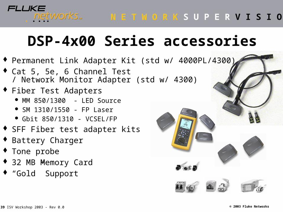
Permanent Link Adapter Kit (std w/ 4000PL/4300) Cat 5, 5e, 6 Channel Test
/ Network Monitor Adapter (std w/ 4300) Fiber Test Adapters
MM 850/1300 - LED Source SM 1310/1550 - FP Laser Gbit 850/1310 - VCSEL/FP
SFF Fiber test adapter kits Battery Charger Tone probe 32 MB Memory Card “Gold” Support
DSP-4x00 Series accessories
Page 40
N E T W O R K S U P E R V I S I O N
© 2003 Fluke Networks40 ISV Workshop 2003 - Rev 0.0
UL Independent Verification Fluke Networks DSP-4X00
series is the only family of cable testers to achieve UL independent verification for compliance with the latest standards.
DSP-4X00 series units exceed Level III accuracy limits.
Bottom Line -- You can trust Fluke Networks.
Page 41
N E T W O R K S U P E R V I S I O N
© 2003 Fluke Networks41 ISV Workshop 2003 - Rev 0.0
DSP-4000 Series Selection Guide
Page 42
N E T W O R K S U P E R V I S I O N
© 2003 Fluke Networks42 ISV Workshop 2003 - Rev 0.0
Copper Testing & CertificationCopper Testing & Certification
Hands-On Time!
Page 43
N E T W O R K S U P E R V I S I O N
© 2003 Fluke Networks43 ISV Workshop 2003 - Rev 0.0
Test Equipment - Ready for Use
Before going into the field Charge & verify battery levels Review performance testing
specs for install Gather appropriate test
adapters & accessories Setup unit with proper test
and report identification Run Self Test Inspect test adapters Bring extra Memory Cards
(if needed)
Ongoing Maintenance Load latest firmware upgrade(s) Self Calibrate (once per month) Self Test (as needed) Calibrate Permanent Link
Adapters to Main / Remote(optional for added accuracy -- once every six months)
Factory calibration (yearly) Visit www.flukenetworks.com
for latest revisions of DSP firmware and LinkWare™
Page 44
N E T W O R K S U P E R V I S I O N
© 2003 Fluke Networks44 ISV Workshop 2003 - Rev 0.0
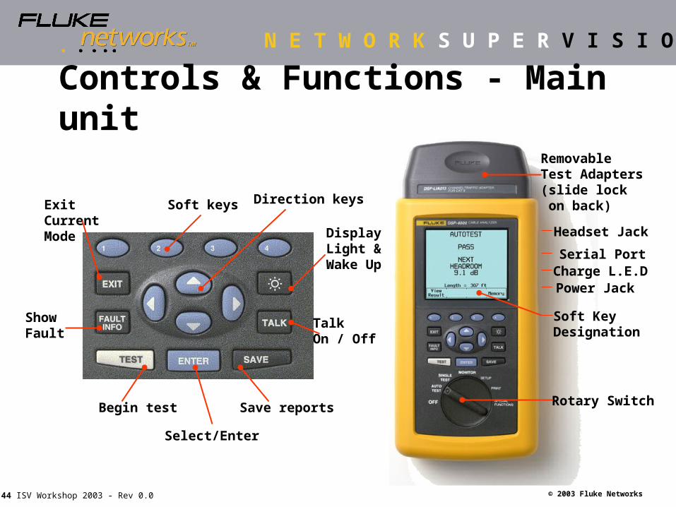
RemovableTest Adapters(slide lock on back)
Serial PortCharge L.E.DPower Jack
Soft KeyDesignation
Rotary SwitchSave reports
DisplayLight &Wake Up
TalkOn / Off
Exit CurrentMode
ShowFault
Soft keys
Headset Jack
Begin test
Select/Enter
Direction keys
Controls & Functions - Main unit
Page 45
N E T W O R K S U P E R V I S I O N
© 2003 Fluke Networks45 ISV Workshop 2003 - Rev 0.0
Removable Test Adapters (slide lock on back)
Charge L.E.DPower Jack
Status Indicators
Rotary Switch
Headset Jack
Serial Port
Status Indications Test Pass Test in Progress Test Fail Talk set active Low Battery
Talk On/Off
Controls & Functions - Remote unit
Page 46
N E T W O R K S U P E R V I S I O N
© 2003 Fluke Networks46 ISV Workshop 2003 - Rev 0.0
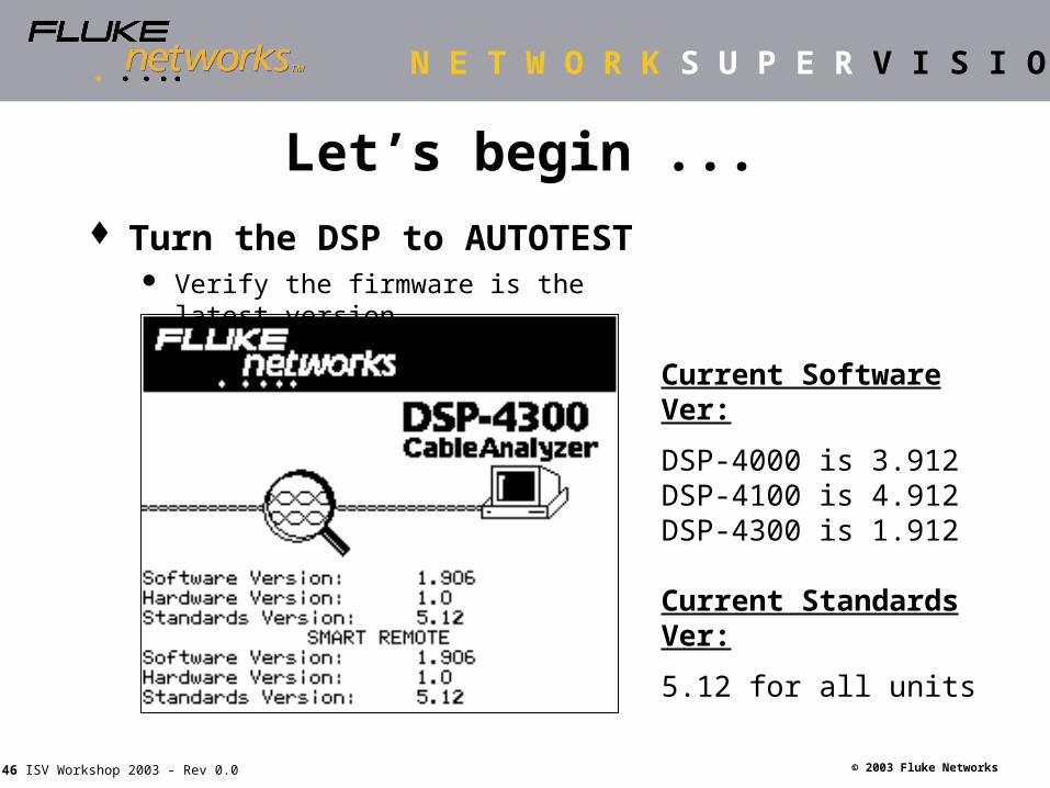
Let’s begin ... Turn the DSP to AUTOTEST
Verify the firmware is the latest version
Current Software Ver:
DSP-4000 is 3.912DSP-4100 is 4.912DSP-4300 is 1.912
Current Standards Ver:
5.12 for all units
Page 47
N E T W O R K S U P E R V I S I O N
© 2003 Fluke Networks47 ISV Workshop 2003 - Rev 0.0
Rotate dial to Special Functions Highlight “Self Calibration” Press ENTER and then TEST
Self Calibration
Page 48
N E T W O R K S U P E R V I S I O N
© 2003 Fluke Networks48 ISV Workshop 2003 - Rev 0.0
Now Setup the test Turn to “SETUP”
Select the correct “link” and cable type
Page 49
N E T W O R K S U P E R V I S I O N
© 2003 Fluke Networks49 ISV Workshop 2003 - Rev 0.0
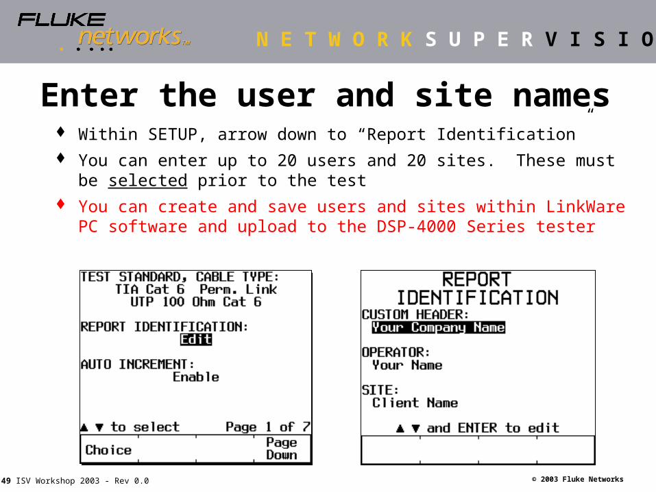
Enter the user and site names Within SETUP, arrow down to “Report Identification” You can enter up to 20 users and 20 sites. These must be selected
prior to the test You can create and save users and sites within LinkWare PC
software and upload to the DSP-4000 Series tester
Page 50
N E T W O R K S U P E R V I S I O N
© 2003 Fluke Networks50 ISV Workshop 2003 - Rev 0.0
Other Setup Options Select / Edit Auto Increment Plot Data Storage
(4100 and 4300 only) Set display time-out Set power down time-out Enable / Disable Audible
beeper Select printer type Set serial port baud rate Set serial port flow control Set date Select Date format
Set time of day Select time of day format Select length in feet / meters Select number format Select print / display language Select power line noise filter
to 50 or 60 Hertz Select impulse noise fault
threshold Select marginal pass ( * ) top
level indication
Page 51
N E T W O R K S U P E R V I S I O N
© 2003 Fluke Networks51 ISV Workshop 2003 - Rev 0.0
Other Setup OptionsMarginal Pass
With this feature enabled, the HDTDX diagnostics will run whenever there is a marginal pass
Page 52
N E T W O R K S U P E R V I S I O N
© 2003 Fluke Networks52 ISV Workshop 2003 - Rev 0.0
Marginal Pass Conditions
Marginal Pass / Fail conditions occur when The measured test data is very
close to the pass/fail test limit line
Due to the tester accuracy, the test measurement can vary within the marginal pass / fail zone
Some cabling warranties will not accept marginal pass test reports
Page 53
N E T W O R K S U P E R V I S I O N
© 2003 Fluke Networks53 ISV Workshop 2003 - Rev 0.0
DSP Setup with LinkWare Software
SETUP is easier to do with LinkWare PC Software
Page 54
N E T W O R K S U P E R V I S I O N
© 2003 Fluke Networks54 ISV Workshop 2003 - Rev 0.0
Talk all you want!
Talk feature allows communication between the main and remote unit
Two lightweight talk sets included
Talk over both copper and fiber
Page 55
N E T W O R K S U P E R V I S I O N
© 2003 Fluke Networks55 ISV Workshop 2003 - Rev 0.0
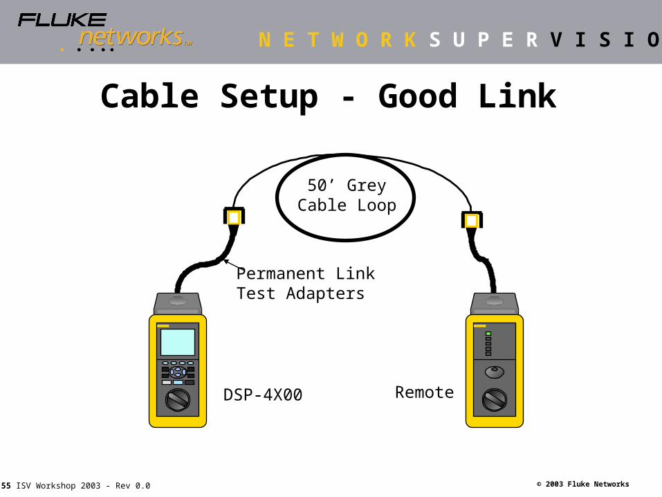
Cable Setup - Good Link
DSP-4X00 Remote
Permanent Link Test Adapters
50’ GreyCable Loop
Page 56
N E T W O R K S U P E R V I S I O N
© 2003 Fluke Networks56 ISV Workshop 2003 - Rev 0.0
AUTOTEST Project Screen
The AUTOTEST project screen displays the test type, plot data selection, memory card status, and battery levels.
On the DSP-4300, the unit predicts how many AUTOTESTs can be made with the remaining charge.
Page 57
N E T W O R K S U P E R V I S I O N
© 2003 Fluke Networks57 ISV Workshop 2003 - Rev 0.0
WIRING CLOSETWIRING CLOSET
HORIZONTAL CABLE
WALL OUTLET
WORK AREAWORK AREAPATCHPANEL
DSP-4X00
Smart Remote
CAT 5e Cable Certification
Just Push Test!
Page 58
N E T W O R K S U P E R V I S I O N
© 2003 Fluke Networks58 ISV Workshop 2003 - Rev 0.0
Individual Test Results Overall Result
All tests Pass PASS
One or more tests Pass* All other tests Pass
PASS*
One or more tests Fail* All other tests Pass(*)
FAIL*
One or more tests Fail FAIL
Autotest Results – Pass or Fail?
* Marginal result
Page 59
N E T W O R K S U P E R V I S I O N
© 2003 Fluke Networks59 ISV Workshop 2003 - Rev 0.0
Autotest Results – NEXT Headroom An indication of the overall quality of the link Headroom is the worst margin of the weakest
performing pair
Page 60
N E T W O R K S U P E R V I S I O N
© 2003 Fluke Networks60 ISV Workshop 2003 - Rev 0.0
View and Save Test Results View Results provides a summary of all tests
performed and required by the chosen standard Highlight any test parameter and press ENTER
for more information
Push the “View Result”button to reviewindividual tests
Remember to push “SAVE”
Page 61
N E T W O R K S U P E R V I S I O N
© 2003 Fluke Networks61 ISV Workshop 2003 - Rev 0.0
Cable Identification Agree on a labeling scheme Keep it simple … fewer characters are better Ensure that the name used to save a cable test,
matches the printed label on both the patch panel and outlet
Look to the ANSI/TIA/EIA-606-A Standards for labeling guidelines (LinkWare software can help)
Page 62
N E T W O R K S U P E R V I S I O N
© 2003 Fluke Networks62 ISV Workshop 2003 - Rev 0.0
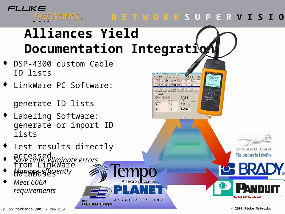
Labeling Software
and Labels
Cable Management
Software (CMS)
Cable Testers and
Test Software
Alliances Yield Documentation Integration
DSP-4300 custom Cable ID lists
LinkWare PC Software: generate ID lists
Labeling Software: generate or import ID lists
Test results directly accessedfrom LinkWare databases
Save time; eliminate errors Manage efficiently Meet 606A
requirements
Page 63
N E T W O R K S U P E R V I S I O N
© 2003 Fluke Networks63 ISV Workshop 2003 - Rev 0.0
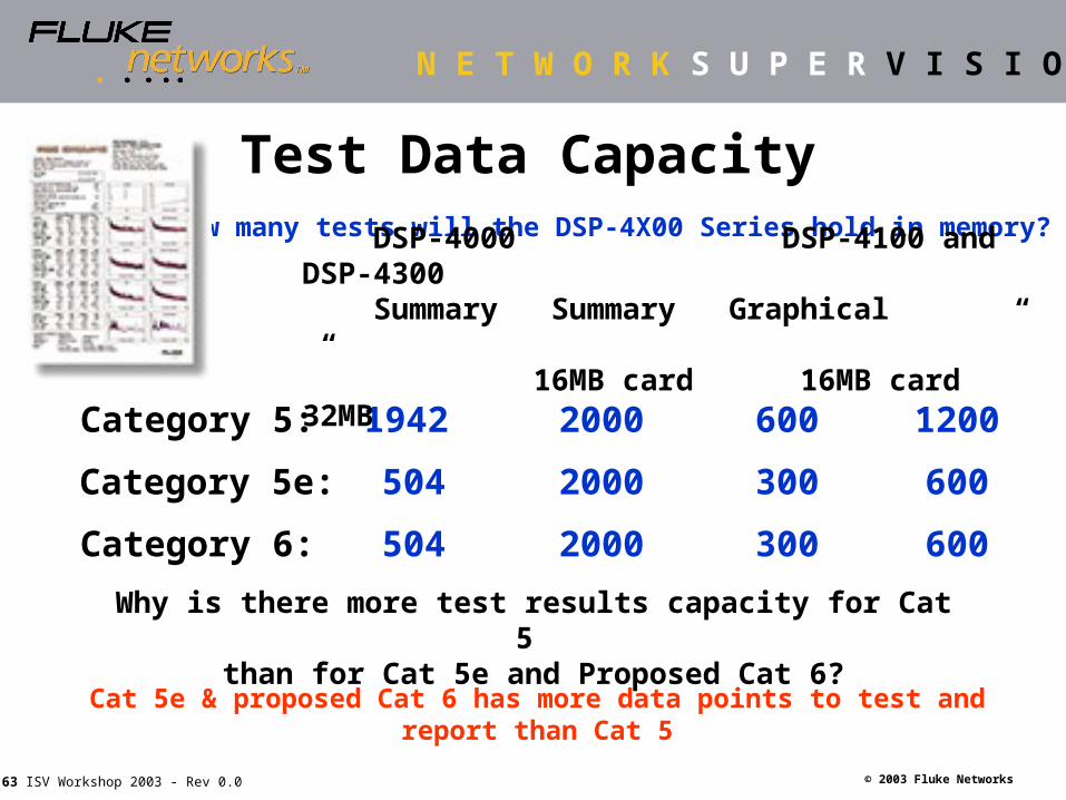
Test Data CapacityHow many tests will the DSP-4X00 Series hold in memory?
Why is there more test results capacity for Cat 5 than for Cat 5e and Proposed Cat 6?
Cat 5e & proposed Cat 6 has more data points to test and report than Cat 5
Category 5:
Category 5e:
Category 6:
1942
504
504
2000
2000
2000
DSP-4000 DSP-4100 and DSP-4300 Summary Summary Graphical “ “ 16MB card 16MB card 32MB
600
300
300
1200
600
600
Page 64
N E T W O R K S U P E R V I S I O N
© 2003 Fluke Networks64 ISV Workshop 2003 - Rev 0.0
Utilizes standard Sandisk MMC’s Standard card - 16 Mbytes Optional card - 32 Mbytes
Separate card reader included Keep the DSP in the field
Create Custom Reports Co. logo & graphical data plots
Eliminate the need to re-test in field Store and transfer every data
point with the DSP-4300 Re-certify to a new standard at a
later date with Cable Manager
The difference between
the DSP-4000 and 4100/4300
Test Results Management --Removable Memory Card
Page 65
N E T W O R K S U P E R V I S I O N
© 2003 Fluke Networks65 ISV Workshop 2003 - Rev 0.0
DSP-4X00 Series
OMNIScanner2
The New Standard for Test Results Documentation
Test Results Management --LinkWare PC Software
Page 66
N E T W O R K S U P E R V I S I O N
© 2003 Fluke Networks66 ISV Workshop 2003 - Rev 0.0
Page 67
N E T W O R K S U P E R V I S I O N
© 2003 Fluke Networks67 ISV Workshop 2003 - Rev 0.0
Example: You have the ID “FLR1 CAB1 BOX 1 23” in the DSP. Using the Import Wizard in LinkWare, the 606-A Tree will be
created within LinkWare and sort the test results accordingly
Test Results Management --LinkWare helps with TIA 606-A Standards
Page 68
N E T W O R K S U P E R V I S I O N
© 2003 Fluke Networks68 ISV Workshop 2003 - Rev 0.0
Test Results Management --Printed Reports
• LinkWare Software supports several alternatives to provide test results information to your customer:– Graphical color report with measured
test points over full frequency range (1 - 350 Mhz)
– Text format with worst case and worst value data
– Summary report which provides a list of the cabling links tested and key information
– Reports can be printed on paper or sent to an electronic PDF file.
Page 69
N E T W O R K S U P E R V I S I O N
© 2003 Fluke Networks69 ISV Workshop 2003 - Rev 0.0
Documentation Suggestions
ALWAYS save test results to a PC Make two copies of the data Print Results to paper or PDF files Do not delete results on the memory cards
until you have double-checked the results on the printed output.
Page 70
N E T W O R K S U P E R V I S I O N
© 2003 Fluke Networks70 ISV Workshop 2003 - Rev 0.0
What if ...What if ...
The link doesn’t pass?
Page 71
N E T W O R K S U P E R V I S I O N
© 2003 Fluke Networks71 ISV Workshop 2003 - Rev 0.0
Causes of Certification Failures Broken Wires (opens) Shorts Split Pairs Excessive Untwisting (13mm max. for Cat 5e) Damaged Cables (crushed) Component(s) are below the category tested Cable performance is below the category tested Test Lead does not match category being tested Incorrect Setting On Cable Tester
Page 72
N E T W O R K S U P E R V I S I O N
© 2003 Fluke Networks72 ISV Workshop 2003 - Rev 0.0
If the test fails push Fault Info
Time Domain X-Talk AnalyzerAutomated Fault Info
Find the fault and then analyze the fault
Unique Digital Test Technology
Page 73
N E T W O R K S U P E R V I S I O N
© 2003 Fluke Networks73 ISV Workshop 2003 - Rev 0.0
Cable Setup - Bad Links
Yellow cable
Red cable
Blue cable
Black cableDSP-4X00 Remote
Permanent Link Test Adapters
50’ GreyCable Loop
50’ GreyCable Loop
6’Cable
Page 74
N E T W O R K S U P E R V I S I O N
© 2003 Fluke Networks74 ISV Workshop 2003 - Rev 0.0
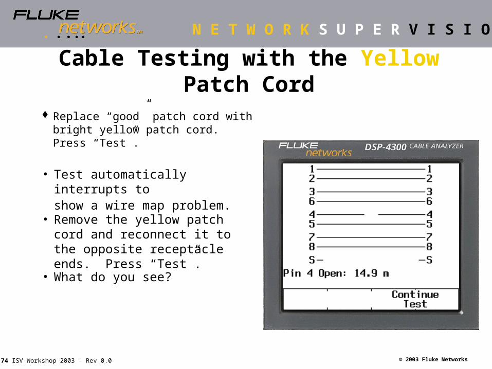
• Test automatically interrupts to show a wire map problem.
Cable Testing with the Yellow Patch Cord
Replace “good” patch cord with bright yellow patch cord. Press “Test”.
• Remove the yellow patch cord and reconnect it to the opposite receptacle ends. Press “Test”.
• What do you see?
Page 75
N E T W O R K S U P E R V I S I O N
© 2003 Fluke Networks75 ISV Workshop 2003 - Rev 0.0
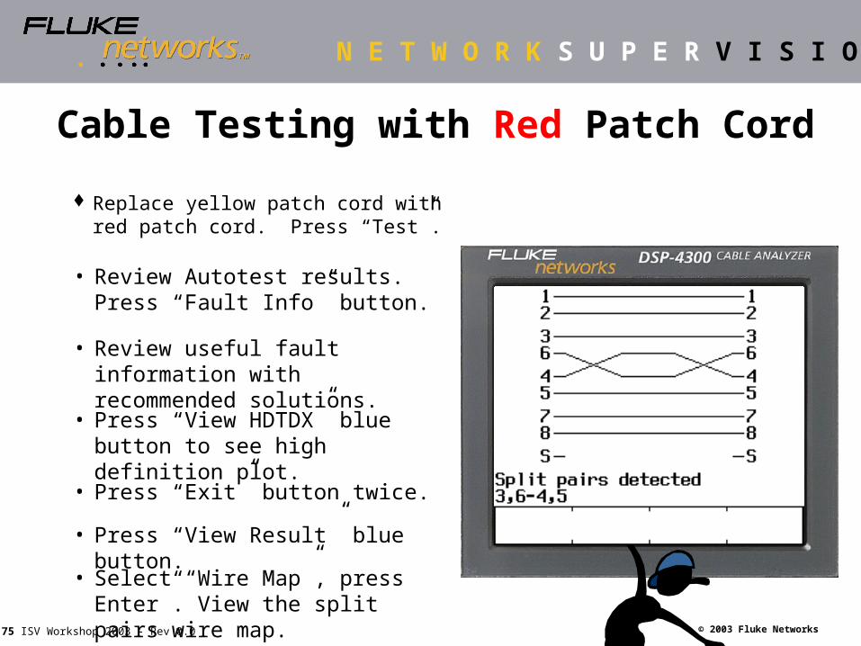
Cable Testing with Red Patch Cord
Replace yellow patch cord with red patch cord. Press “Test”.
• Review Autotest results. Press “Fault Info” button.
• Review useful fault information with recommended solutions.
• Press “View HDTDX” blue button to see high definition plot.
• Press “Exit” button twice.
• Press “View Result” blue button.
• Select “Wire Map”, press Enter”. View the split pairs wire map.
Page 76
N E T W O R K S U P E R V I S I O N
© 2003 Fluke Networks76 ISV Workshop 2003 - Rev 0.0
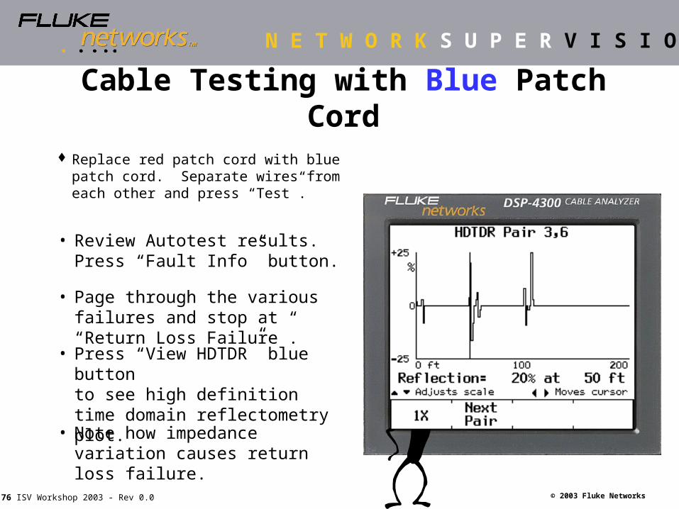
Cable Testing with Blue Patch Cord
Replace red patch cord with blue patch cord. Separate wires from each other and press “Test”.
• Press “View HDTDR” blue button to see high definition time domain reflectometry plot.
• Page through the various failures and stop at “Return Loss Failure”.
• Note how impedance variation causes return loss failure.
• Review Autotest results. Press “Fault Info” button.
Page 77
N E T W O R K S U P E R V I S I O N
© 2003 Fluke Networks77 ISV Workshop 2003 - Rev 0.0
Cable Testing with Black Patch Cord
Replace blue patch cord with black patch cord. Press “Test”.
• Test finishes and displays Autotest results. Press “Fault Info” button for more info.
• Press “View HDTDX” blue button to see high definition time domain crosstalk plot.
• Fault Info provides the exact location of the problem and recommended solution.
• The unique digital technology pinpoints problems -- even in the middle of the cable!
Page 78
N E T W O R K S U P E R V I S I O N
© 2003 Fluke Networks78 ISV Workshop 2003 - Rev 0.0
Patch Cord and Spool Test Patch Cord and Spool Test SolutionSolution
How do we know whether a patch cord meets the requirements?
Page 79
N E T W O R K S U P E R V I S I O N
© 2003 Fluke Networks79 ISV Workshop 2003 - Rev 0.0
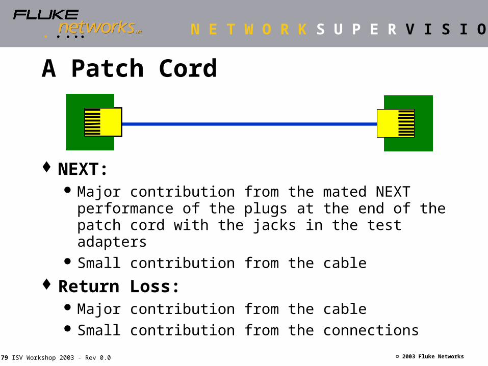
A Patch Cord
NEXT: Major contribution from the mated NEXT
performance of the plugs at the end of the patch cord with the jacks in the test adapters
Small contribution from the cable
Return Loss: Major contribution from the cable Small contribution from the connections
Page 80
N E T W O R K S U P E R V I S I O N
© 2003 Fluke Networks80 ISV Workshop 2003 - Rev 0.0
Standards Define Patch Cord Test
TIA/EIA-568-B.2-1 Paragraph 7.2.1.3: NEXT Loss
NEXT Loss of near-end connection Worst-case addition of the NEXT Loss of the remote
connection compensated for the round trip attenuation of the cable
Plus NEXT of patch cord cable Plus an allowance for reflected FEXT (=0.5 dB)
NEXT Loss test limits of patch cords is length-dependent
Very similar to latest draft of IEC 61935-2
Page 81
N E T W O R K S U P E R V I S I O N
© 2003 Fluke Networks81 ISV Workshop 2003 - Rev 0.0
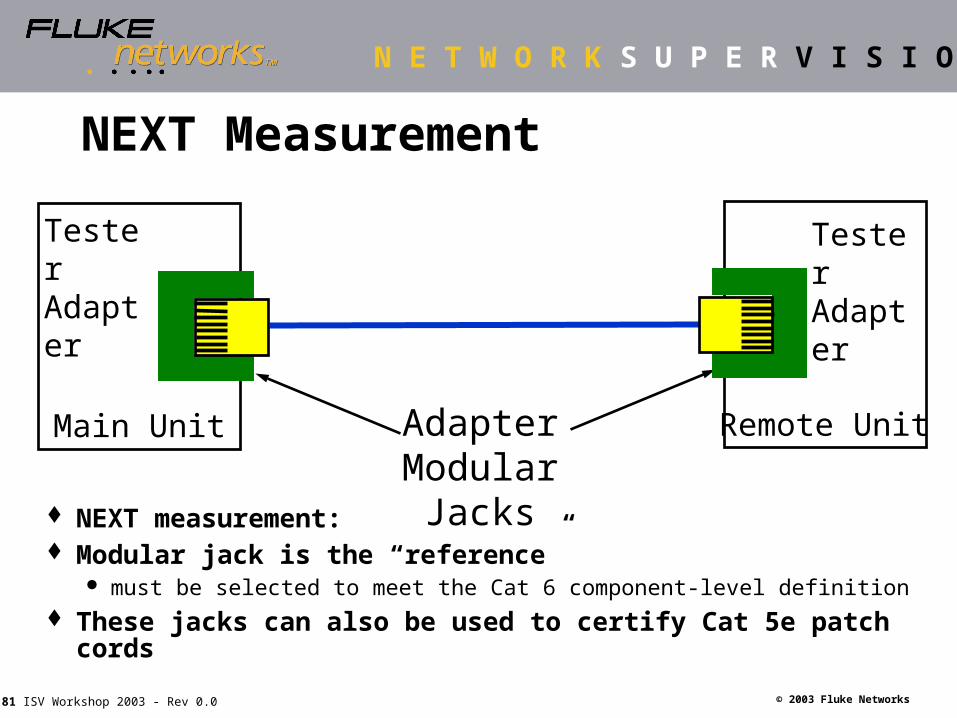
AdapterModular Jacks
NEXT Measurement
NEXT measurement: Modular jack is the “reference”
must be selected to meet the Cat 6 component-level definition These jacks can also be used to certify Cat 5e patch cords
Tester Adapter
Remote Unit
Tester Adapter
Main Unit
Page 82
N E T W O R K S U P E R V I S I O N
© 2003 Fluke Networks82 ISV Workshop 2003 - Rev 0.0
Return Loss Measurement
Tester Adapter
Main Unit
Main unit is (factory) calibrated using one-port calibration (Open, Short and 100 Ω load)
To diminish effect of far-end termination:5 dB attenuation circuit in remote adapter
Attenuation Circuit (5dB) for each wire pair
Tester Adapter
Remote Unit
Page 83
N E T W O R K S U P E R V I S I O N
© 2003 Fluke Networks83 ISV Workshop 2003 - Rev 0.0
Product Offering
Product description: Patch Cord Test Model: DSP-PCI-6S Contains two adapters (main and remote)
Main unit adapter: DSP-PCI-M6 remote unit adapter: DSP-PCI-R6
A CD-ROM Manual for Patch Cord / Spool Test Test data base to be downloaded in the DSP-4X00 Test data base includes main link model tests as well as patch
cord and spool test specifications Data sheet
Page 84
N E T W O R K S U P E R V I S I O N
© 2003 Fluke Networks84 ISV Workshop 2003 - Rev 0.0
Spool Test Verify the quality of
the cable before installing or processing
Supports solid core horizontal cable and stranded cable to construct patch cords
Page 85
N E T W O R K S U P E R V I S I O N
© 2003 Fluke Networks85 ISV Workshop 2003 - Rev 0.0
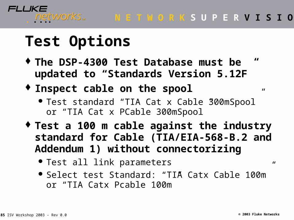
Test Options The DSP-4300 Test Database must be
updated to “Standards Version 5.12F” Inspect cable on the spool
Test standard “TIA Cat x Cable 300mSpool” or “TIA Cat x PCable 300mSpool”
Test a 100 m cable against the industry standard for Cable (TIA/EIA-568-B.2 and Addendum 1) without connectorizing Test all link parameters Select test Standard: “TIA Catx Cable 100m” or
“TIA Catx Pcable 100m”
Page 86
N E T W O R K S U P E R V I S I O N
© 2003 Fluke Networks86 ISV Workshop 2003 - Rev 0.0
Test Setup
Select appropriate standard in the ‘Setup’ mode
Page 87
N E T W O R K S U P E R V I S I O N
© 2003 Fluke Networks87 ISV Workshop 2003 - Rev 0.0
Spool Test Results
Page 88
N E T W O R K S U P E R V I S I O N
© 2003 Fluke Networks88 ISV Workshop 2003 - Rev 0.0
DSP- 4X00 Series Cable DSP- 4X00 Series Cable AnalyzersAnalyzers
Summary of Benefits
Page 89
N E T W O R K S U P E R V I S I O N
© 2003 Fluke Networks89 ISV Workshop 2003 - Rev 0.0
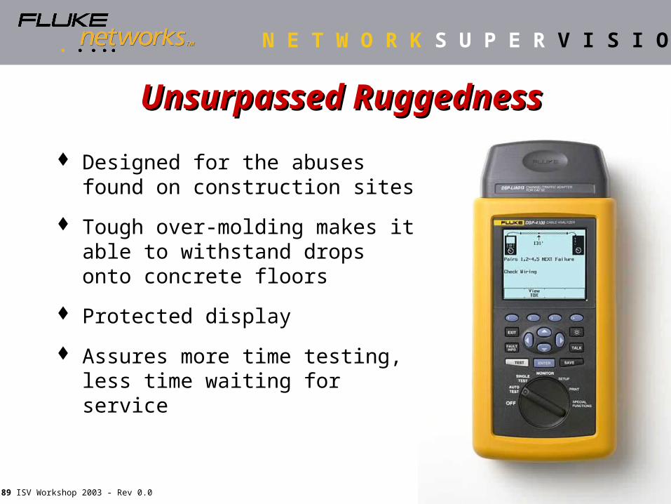
Unsurpassed RuggednessUnsurpassed Ruggedness
Designed for the abuses found on construction sites
Tough over-molding makes it able to withstand drops onto concrete floors
Protected display
Assures more time testing, less time waiting for service
Page 90
N E T W O R K S U P E R V I S I O N
© 2003 Fluke Networks90 ISV Workshop 2003 - Rev 0.0
Test in 3 Simple Steps
1. Turn to Autotest
2. Press [TEST]
3. Press [Save]
Easy to select test standards
If a link fails a test, simply press [FAULT INFO]
Spend less time training, more time testing!
Easy-to-UseEasy-to-Use
Page 91
N E T W O R K S U P E R V I S I O N
© 2003 Fluke Networks91 ISV Workshop 2003 - Rev 0.0
Unique Permanent Link SolutionUnique Permanent Link Solution More Passes!
(Fewer RL false failures)
Patent pending designusing precision cable
Removable connector head assembly for flexible change out of vendor specific plugs
Higher accuracy
Ruggedized patch cord provides longer life
Page 92
N E T W O R K S U P E R V I S I O N
© 2003 Fluke Networks92 ISV Workshop 2003 - Rev 0.0
Superior Diagnostics with Digital TestingSuperior Diagnostics with Digital Testing
FaultInfo
Page 93
N E T W O R K S U P E R V I S I O N
© 2003 Fluke Networks93 ISV Workshop 2003 - Rev 0.0
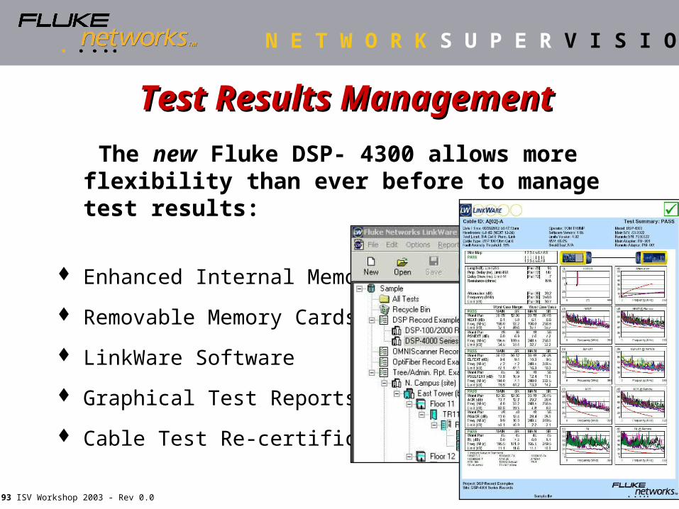
Test Results ManagementTest Results Management
The new Fluke DSP- 4300 allows more flexibility than ever before to manage test results:
Enhanced Internal Memory
Removable Memory Cards
LinkWare Software
Graphical Test Reports
Cable Test Re-certification
Page 94
N E T W O R K S U P E R V I S I O N
© 2003 Fluke Networks94 ISV Workshop 2003 - Rev 0.0
Digital Test Technology gets the job done right the first time.
Instantaneous and complete diagnostics save hours of blind troubleshooting.
Graphical test data storage and transport system keeps tester in the field generating revenue.
LinkWare® “freeware” allows simple electronic management of test data.
Laboratory grade Permanent Link Adapters eliminate unnecessary test failures.
DSP Cable Analyzer - What’s in it for me?
Page 95
N E T W O R K S U P E R V I S I O N
© 2003 Fluke Networks95 ISV Workshop 2003 - Rev 0.0
On-Line Reference Material Statement of Work – proposed text for Field
test requirements:
www.fluke-net.com/consultants
Technical reference web site:
www.cabletesting.com
Fluke Networks’ government web site:
www.flukenetworks.ca/government