Annu. Rev. Phys. Chem. 2006. 57:303–31 doi: 10.1146/annurev.physchem.56.092503.141236 Copyright c 2006 by Annual Reviews. All rights reserved First published online as a Review in Advance on December 16, 2005 NEAR-FIELD OPTICAL MICROSCOPY AND SPECTROSCOPY WITH P OINTED PROBES ∗ Lukas Novotny 1 and Stephan J. Stranick 2 1 The Institute of Optics, University of Rochester, Rochester, New York 14627; email: [email protected]2 Surface and Microanalysis Science Division, National Institute of Standards and Technology, Gaithersburg, Maryland 20899; email: [email protected]Key Words scatter-probe, enhanced-probe, evanescent-probe ■ Abstract In recent years, developments in near-field techniques exploiting far- field illumination of a pointed, apertureless probe have demonstrated a newfound ex- citement. This is due in part to the advantages afforded by apertureless techniques that allow for the practical implementation of spectroscopic contrast mechanisms at length scales below 100 nm. These mechanisms include Raman and infrared absorption for chemical contrast, as well as materials contrast based on dielectric dispersion. In this review, we briefly describe the evolution of the field from the “classical” aperture-based approach toward the development of near-field optical microscopy with pointed probes. We highlight advances in state-of-the-art theory that describe the field distribution un- der an illuminated probe, as well as advances in the experimental implementation of scattering and excitation probe techniques. INTRODUCTION Progress in science and medicine is often triggered by new techniques and instru- mentation.In the words of Nobel Laureate Rosalyn Yalow, “New Truths become evident when new tools become available.” Through the development and imple- mentation of new microscopy and spectroscopy techniques, we have increased our understanding of physical phenomena ranging from the atomic structure of superconductors to the structure and function of living cells. These advances aside, numerous challenges remain. Often, the physical and chemical properties of nanometer-scale systems are studied by isolating specific components from their natural environment to employ standard/conventional spectroscopic tech- niques. For example, in nanotechnology one often attempts to understand the ∗ The U.S. Government has the right to retain a nonexclusive, royalty-free license in and to any copyright covering this paper. 0066-426X/06/0505-0303$20.00 303 Annu. Rev. Phys. Chem. 2006.57:303-331. Downloaded from arjournals.annualreviews.org by Dr. Lukas Novotny on 05/01/06. For personal use only.
Transcript
1 Mar 2006 15:26 AR ANRV272-PC57-11.tex XMLPublishSM(2004/02/24) P1: IKH
1The Institute of Optics, University of Rochester, Rochester, New York 14627;email: [email protected] and Microanalysis Science Division, National Institute of Standards andTechnology, Gaithersburg, Maryland 20899; email: [email protected]
Key Words scatter-probe, enhanced-probe, evanescent-probe
■ Abstract In recent years, developments in near-field techniques exploiting far-field illumination of a pointed, apertureless probe have demonstrated a newfound ex-citement. This is due in part to the advantages afforded by apertureless techniques thatallow for the practical implementation of spectroscopic contrast mechanisms at lengthscales below 100 nm. These mechanisms include Raman and infrared absorption forchemical contrast, as well as materials contrast based on dielectric dispersion. In thisreview, we briefly describe the evolution of the field from the “classical” aperture-basedapproach toward the development of near-field optical microscopy with pointed probes.We highlight advances in state-of-the-art theory that describe the field distribution un-der an illuminated probe, as well as advances in the experimental implementation ofscattering and excitation probe techniques.
INTRODUCTION
Progress in science and medicine is often triggered by new techniques and instru-mentation. In the words of Nobel Laureate Rosalyn Yalow, “New Truths becomeevident when new tools become available.” Through the development and imple-mentation of new microscopy and spectroscopy techniques, we have increasedour understanding of physical phenomena ranging from the atomic structure ofsuperconductors to the structure and function of living cells. These advancesaside, numerous challenges remain. Often, the physical and chemical propertiesof nanometer-scale systems are studied by isolating specific components fromtheir natural environment to employ standard/conventional spectroscopic tech-niques. For example, in nanotechnology one often attempts to understand the
∗The U.S. Government has the right to retain a nonexclusive, royalty-free license in and to
any copyright covering this paper.
0066-426X/06/0505-0303$20.00 303
Ann
u. R
ev. P
hys.
Che
m. 2
006.
57:3
03-3
31. D
ownl
oade
d fr
om a
rjou
rnal
s.an
nual
revi
ews.
org
by D
r. L
ukas
Nov
otny
on
05/0
1/06
. For
per
sona
l use
onl
y.
Report Documentation Page Form ApprovedOMB No. 0704-0188
Public reporting burden for the collection of information is estimated to average 1 hour per response, including the time for reviewing instructions, searching existing data sources, gathering andmaintaining the data needed, and completing and reviewing the collection of information. Send comments regarding this burden estimate or any other aspect of this collection of information,including suggestions for reducing this burden, to Washington Headquarters Services, Directorate for Information Operations and Reports, 1215 Jefferson Davis Highway, Suite 1204, ArlingtonVA 22202-4302. Respondents should be aware that notwithstanding any other provision of law, no person shall be subject to a penalty for failing to comply with a collection of information if itdoes not display a currently valid OMB control number.
1. REPORT DATE 2006 2. REPORT TYPE
3. DATES COVERED 00-00-2006 to 00-00-2006
4. TITLE AND SUBTITLE Near-Field Optical Microscopy and Spectroscopy with Pointed Probes
5a. CONTRACT NUMBER
5b. GRANT NUMBER
5c. PROGRAM ELEMENT NUMBER
6. AUTHOR(S) 5d. PROJECT NUMBER
5e. TASK NUMBER
5f. WORK UNIT NUMBER
7. PERFORMING ORGANIZATION NAME(S) AND ADDRESS(ES) University of Rochester,The Institute of Optics,Rochester,NY,14627
8. PERFORMING ORGANIZATIONREPORT NUMBER
9. SPONSORING/MONITORING AGENCY NAME(S) AND ADDRESS(ES) 10. SPONSOR/MONITOR’S ACRONYM(S)
11. SPONSOR/MONITOR’S REPORT NUMBER(S)
12. DISTRIBUTION/AVAILABILITY STATEMENT Approved for public release; distribution unlimited
13. SUPPLEMENTARY NOTES
14. ABSTRACT see report
15. SUBJECT TERMS
16. SECURITY CLASSIFICATION OF: 17. LIMITATION OF ABSTRACT Same as
Report (SAR)
18. NUMBEROF PAGES
29
19a. NAME OFRESPONSIBLE PERSON
a. REPORT unclassified
b. ABSTRACT unclassified
c. THIS PAGE unclassified
Standard Form 298 (Rev. 8-98) Prescribed by ANSI Std Z39-18
1 Mar 2006 15:26 AR ANRV272-PC57-11.tex XMLPublishSM(2004/02/24) P1: IKH
304 NOVOTNY � STRANICK
nanometer-scale building blocks in an isolated form before assembling them intoa functional device. However, the properties of the building blocks can changeonce they are embedded into a macroscopic structure. This change is due to in-teractions between the building blocks and their environment. Interestingly, manynanometer-scale biological systems function only in their native environment. Forexample, the specific function of certain membrane proteins depends on the pres-ence of other neighboring proteins (e.g., energy transfer between light-harvestingcomplexes in photosynthetic membranes). Thus, the challenge is to develop toolsthat perform measurements on complex, heterogeneous nanometer-scale systemswith the same exacting level of chemical and physical detail that conventional mi-croscopic and spectroscopic techniques currently provide on macroscopic samplesystems.
Common high-resolution instruments for the characterization of surfaces in-clude electron microscopy and scanning-probe microscopy. Recent experimentshave demonstrated the ability of these techniques to image and manipulatematerials ranging from individual atoms to proteins. However, without any priorknowledge about the specimen, it is often difficult or challenging to identifythe constituent parts. This challenge is mainly a result of the fact that electronmicroscopy and most scanning-probe microscopies render high-resolution topo-graphic images with little or no chemical information. The lack of chemical in-formation is related to the particular molecular structure and composition of thesample. The chemical information can, however, be retrieved from probing thebond energies between adjacent atoms.
Optical spectroscopy provides a wealth of information on structural and dynam-ical properties of materials. This is because the energies of light quanta (photons)lie in the energy range of electronic and vibrational transitions in matter. Combin-ing optical spectroscopy with microscopy is especially desirable because spectralfeatures can then be spatially resolved. However, the diffraction limit has preventedresearchers from resolving features smaller than half a wavelength of the appliedradiation. Two decades ago, it was demonstrated that near-field optical microscopy(1, 2) was able to extend the range of optical measurements beyond the diffractionlimit. Although the attainable spatial resolution does not presently compare torelated scanning-probe techniques (e.g., scanning-tunneling microscopy), it is thecombination of resolution and chemical information that makes near-field opticalmicroscopy attractive (see Figure 1).
Over the past 10 years, developments in near-field optical microscopy havebeen summarized in several review articles and books (3–10). Our intention isnot to provide another wide-spanning review of near-field optical microscopybut to describe a relatively new trend based on laser-irradiated pointed probes.Here, we briefly describe the “classical” aperture-based approach and give a roughhistorical account of the development and application of near-field optical mi-croscopy and spectroscopy with pointed probes often referred to as aperturelessprobes.
Ann
u. R
ev. P
hys.
Che
m. 2
006.
57:3
03-3
31. D
ownl
oade
d fr
om a
rjou
rnal
s.an
nual
revi
ews.
org
by D
r. L
ukas
Nov
otny
on
05/0
1/06
. For
per
sona
l use
onl
y.
1 Mar 2006 15:26 AR ANRV272-PC57-11.tex XMLPublishSM(2004/02/24) P1: IKH
SPECTROSCOPY WITH POINTED PROBES 305
Figure 1 Chemical specificity versus spatial resolution for different microscopic
techniques. Near-field scanning optical microscopy (NSOM) achieves an excellent
product of the two factors.
APERTURE-BASED NEAR-FIELD OPTICAL MICROSCOPY
As illustrated in Figure 2, the spatial resolution �x of standard optical microscopyis limited by diffraction to roughly (Abbe criterion)
�x = 0.61λ/NA.
Here, λ is the wavelength of the interacting radiation, and NA = n sin α is the nu-merical aperture of the objective lens. The NA can be increased by a large index ofrefraction n of the surrounding medium or a large angle of acceptance α. The lattertwo tricks are routinely applied in confocal microscopy (e.g., solid immersion–lens microscopy and 4π -microscopy). By using prior information about the sampleproperties (e.g., the energy-level structure of dye molecules) or by applying non-linear or saturation effects (e.g., multiphoton-confocal microscopy and stimulateddepletion), it is possible to stretch the Abbe resolution criterion further.
Ann
u. R
ev. P
hys.
Che
m. 2
006.
57:3
03-3
31. D
ownl
oade
d fr
om a
rjou
rnal
s.an
nual
revi
ews.
org
by D
r. L
ukas
Nov
otny
on
05/0
1/06
. For
per
sona
l use
onl
y.
1 Mar 2006 15:26 AR ANRV272-PC57-11.tex XMLPublishSM(2004/02/24) P1: IKH
306 NOVOTNY � STRANICK
Figure 2 Comparison of diffraction-limited optical microscopy and near-field optical mi-
croscopy. (a) Schematic representation of the diffraction limit showing the minimum de-
tectable separation of two light scatterers. (b) Schematic of aperture scanning near-field
microscopy. To first approximation, resolution is defined by the aperture size and not by the
wavelength of the exciting radiation.
In near-field optical microscopy, the resolution�x no longer depends onλbut ona characteristic length d (e.g., aperture diameter or tip diameter) of a local probe.Near-field optical microscopy relies on a confined photon flux between a localprobe and the sample surface. The probe is raster-scanned over the sample surface,and for predefined positions (x,y) of the probe, a remote detector acquires the opticalresponse. In this way an optical contrast image can be recorded. In Synge’s originalconcept, the local probe consisted of a tiny aperture in a perfectly reflecting metalscreen (11) (see Figure 2b). Immediately behind the irradiated screen, the light fieldis spatially confined to the size of the aperture (d ). Only if a scatterer is within adistance d from the aperture will it interact with the radiation field. Synge’s ideawas soon forgotten after its inception because nanofabrication techniques werenot then available. In the following decades, however, the idea was reinventedseveral times. The first experimental results performed at optical frequencies werepublished by Pohl et al. at the IBM Research Laboratory in Switzerland followedshortly by Lewis et al. at Cornell University (1, 2). A reproduction of the firstnear-field optical measurement is shown in Figure 3.
In the most widely adapted aperture approach, light is sent down an aluminum-coated fiber tip of which the foremost end is left uncoated to form a small aperture(12). Unfortunately, only a tiny fraction of the light coupled into the fiber is emittedthrough the aperture because of the propogation cutoff of the waveguide modes(13). The low-light throughput and the finite skin depth of the metal are the limit-ing factors for resolution. The throughput can be significantly increased by usingprobes with large cone angles (13, 14). Nevertheless, it is doubtful that a repro-ducible artifact-free resolution of 50 nm will be surpassed by the current aperturetechnique. Moreover, the aperture technique has other practical complications
Ann
u. R
ev. P
hys.
Che
m. 2
006.
57:3
03-3
31. D
ownl
oade
d fr
om a
rjou
rnal
s.an
nual
revi
ews.
org
by D
r. L
ukas
Nov
otny
on
05/0
1/06
. For
per
sona
l use
onl
y.
1 Mar 2006 15:26 AR ANRV272-PC57-11.tex XMLPublishSM(2004/02/24) P1: IKH
SPECTROSCOPY WITH POINTED PROBES 307
Figure 3 Early near-field optical scan trace recorded with an aperture-type probe. The data
are from the laboratory book of Winfried Denk, then working with Dieter W. Pohl at the IBM
Research Laboratory in Switzerland. (Figure courtesy of Dieter W. Pohl)
including the following: The difficulty in obtaining a smooth aluminum coatingintroduces nonreproducibility in probe fabrication, the flat ends of the apertureprobes are not suitable for simultaneous topographic imaging with high resolu-tion, and the absorption of light in the metal coating causes significant heating thatposes a problem for temperature-sensitive applications (15, 16). These issues limitthe aperture technique’s impact in key technologies and nanoscience applications.
NEAR-FIELD OPTICAL MICROSCOPYWITH POINTED PROBES
Laser-irradiated pointed probes were introduced to overcome the limitations ofaperture probes and to improve the resolution in near-field optical microscopy (17–25). Two different schemes were established: the local-scattering approach and thelocal-excitation approach. In the local-scattering approach, a pointed probe suchas a tip or a particle is used to locally perturb the fields at a sample surface; theresponse to this perturbation is detected in the far field at the same frequency of theincident light. This scheme relies on the fact that the field near any laser-irradiatedobject is made of waves that propagate away from the object (propagating waves)and also of waves that remain attached to the object’s surface (evanescent waves).The inability of evanescent waves to propagate constitutes the diffraction limit
Ann
u. R
ev. P
hys.
Che
m. 2
006.
57:3
03-3
31. D
ownl
oade
d fr
om a
rjou
rnal
s.an
nual
revi
ews.
org
by D
r. L
ukas
Nov
otny
on
05/0
1/06
. For
per
sona
l use
onl
y.
1 Mar 2006 15:26 AR ANRV272-PC57-11.tex XMLPublishSM(2004/02/24) P1: IKH
308 NOVOTNY � STRANICK
of classical microscopy. However, they can be partially converted to propagatingradiation by using a pointed probe as a local scatterer. Scattering-type measure-ments typically have a high signal-to-noise ratio, but the interpretation of therecorded information is complicated by so-called topographic artifacts (26). Theproblem is related to the fact that the scattering efficiency depends sensitively onthe separation between probe and sample, making the differentiation of true opticalcontrast (related to local-dielectric constant) difficult. Nevertheless, schemes havebeen worked out to largely decouple optical and topographic information. Theseschemes are discussed in more detail in the section on scattering-type near-fieldmicroscopy below.
Instead of using the pointed probe as a local scatterer, one can use it as alocal light source. This is accomplished under the proper polarization and excita-tion conditions through the use of suitable probe materials and probe geometries(27, 28). Under these conditions, the field near the apex of the probe can becomestrongly enhanced over the field of the illuminating laser light, thereby establishinga nanoscopic light source. Thus, instead of using a tip to locally scatter a sample’snear field, one can use the tip to provide a local-excitation source for a spectro-scopic response of the sample (23, 24). As shown in Figure 4 the tip is held a fewnanometers above the sample surface so that a highly localized interaction betweenthe enhanced field and the sample is achieved. This approach enables simultane-ous spectral and sub-diffraction spatial measurements, but it depends sensitivelyon the magnitude of the field-enhancement factor. The local-excitation schemeis commonly referred to as tip-enhanced near-field optical microscopy, and it is
Figure 4 Principle of tip-enhanced near-field optical microscopy. A laser-irradiated metal
tip (polarization along tip axis) enhances the incident electric field near its apex thereby
creating a localized photon source. (a) Schematic of the method. (b) Practical implementation:
A higher-order laser beam is focused on a sample surface, and a sharply pointed metal tip
is positioned into the laser focus. The enhanced fields at the tip locally interact with the
sample surface thereby exciting a spectroscopic response collected by the same objective and
directed on a detector. (c) Scanning electron microscopy image of a sharp gold tip fabricated
by focused-ion beam milling.
Ann
u. R
ev. P
hys.
Che
m. 2
006.
57:3
03-3
31. D
ownl
oade
d fr
om a
rjou
rnal
s.an
nual
revi
ews.
org
by D
r. L
ukas
Nov
otny
on
05/0
1/06
. For
per
sona
l use
onl
y.
1 Mar 2006 15:26 AR ANRV272-PC57-11.tex XMLPublishSM(2004/02/24) P1: IKH
SPECTROSCOPY WITH POINTED PROBES 309
discussed in more detail in the section on local excitation below. In principle, thetwo methods, local excitation and local scattering, are not independent. A strongfield enhancement is a necessary condition for efficient scattering and vice versa.
DEVELOPMENT OF NEAR-FIELD OPTICALMICROSCOPY WITH POINTED PROBES
The use of a light-irradiated particle for achieving subwavelength light localizationwas originally suggested by Synge in a letter to Einstein (29). The idea was neverpublished in its original form because there was concern that the direct exposure ofthe sample to the irradiating light would overshadow the local interaction betweenparticle and sample. Instead in 1928, Synge (11) published an article in which heproposed the use of a tiny aperture in a metal screen to achieve a subwavelength-scale light source (see the section on the aperture technique above). In 1984, evenbefore the invention of the atomic force microscope (AFM), Wessel (30) proposeda concept similar to Synge’s original idea: A laser-irradiated, elongated metal par-ticle is used to establish an enhanced, localized light field. Wessel’s proposal wassoon forgotten, but it resurfaced again in the context of near-field optical micro-copy. In fact, within this field of study several research groups reinvented Wessel’sidea. Denk & Pohl (22) suggested using the enhanced field at a metal tip in combi-nation with nonlinear-optical spectroscopy, and Fischer & Pohl (31) produced thefirst experimental results demonstrating the field-enhancement effect associatedwith a single metal nanoparticle. In the following years, metal tips were introducedas scattering centers to convert the nonpropagating evanescent fields near the sur-face of an object into propagating radiation. This was the initial approach takenby Inouye & Kawata (17). In their paper they speculate about a combination ofmetal tips with surface-enhanced spectroscopy. Similar scattering-type approacheswere pursued by the groups of Boccara (32) and Wickramasinghe (18). The latterimplemented an interferometric detection scheme for the locally perturbed nearfield. However, the origin of the contrast in the recorded images was long debated.Keilmann and coworkers (20, 21) pursued a parallel effort in scattering-type near-field microscopy with experiments performed at radio frequencies and later in theinfrared. Recently, this group has established the possibility of extracting variousoptical parameters using a pointed probe as a local scatterer (33, 34).
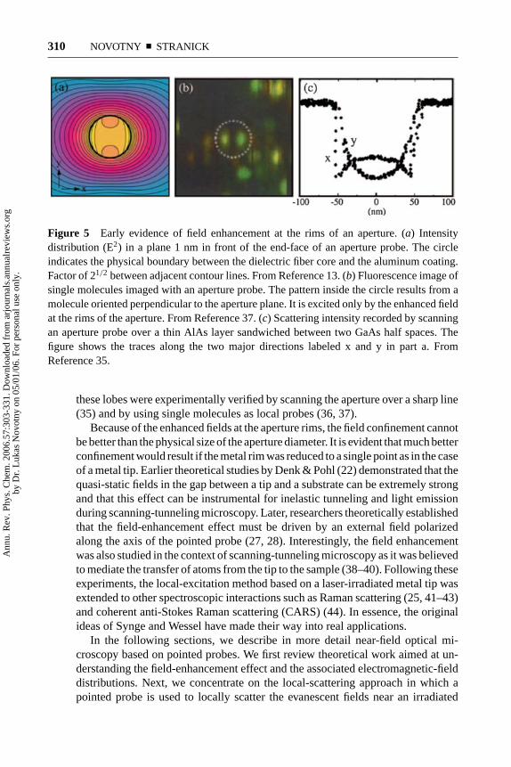
Although local-scattering near-field optical microscopy has found important ap-plications in materials science, it is not inherently a spectroscopic technique. Theuse of the field-enhancement effect near a metal tip for localized spectroscopicmeasurements was theoretically formulated in Reference 23 and subsequentlyexperimentally demonstrated by Sanchez et al. (24) using two-photon excited flu-orescence. This approach was inspired by the field distribution near a tiny apertureas shown in Figure 5a. The field is dominated by two strong lobes near the rims ofthe aperture. These lobes are located in the direction of the incident polarizationand originate from surface charges accumulating at the rims. As shown in Figure 5,
Ann
u. R
ev. P
hys.
Che
m. 2
006.
57:3
03-3
31. D
ownl
oade
d fr
om a
rjou
rnal
s.an
nual
revi
ews.
org
by D
r. L
ukas
Nov
otny
on
05/0
1/06
. For
per
sona
l use
onl
y.
1 Mar 2006 15:26 AR ANRV272-PC57-11.tex XMLPublishSM(2004/02/24) P1: IKH
310 NOVOTNY � STRANICK
Figure 5 Early evidence of field enhancement at the rims of an aperture. (a) Intensity
distribution (E2) in a plane 1 nm in front of the end-face of an aperture probe. The circle
indicates the physical boundary between the dielectric fiber core and the aluminum coating.
Factor of 21/2 between adjacent contour lines. From Reference 13. (b) Fluorescence image of
single molecules imaged with an aperture probe. The pattern inside the circle results from a
molecule oriented perpendicular to the aperture plane. It is excited only by the enhanced field
at the rims of the aperture. From Reference 37. (c) Scattering intensity recorded by scanning
an aperture probe over a thin AlAs layer sandwiched between two GaAs half spaces. The
figure shows the traces along the two major directions labeled x and y in part a. From
Reference 35.
these lobes were experimentally verified by scanning the aperture over a sharp line(35) and by using single molecules as local probes (36, 37).
Because of the enhanced fields at the aperture rims, the field confinement cannotbe better than the physical size of the aperture diameter. It is evident that much betterconfinement would result if the metal rim was reduced to a single point as in the caseof a metal tip. Earlier theoretical studies by Denk & Pohl (22) demonstrated that thequasi-static fields in the gap between a tip and a substrate can be extremely strongand that this effect can be instrumental for inelastic tunneling and light emissionduring scanning-tunneling microscopy. Later, researchers theoretically establishedthat the field-enhancement effect must be driven by an external field polarizedalong the axis of the pointed probe (27, 28). Interestingly, the field enhancementwas also studied in the context of scanning-tunneling microscopy as it was believedto mediate the transfer of atoms from the tip to the sample (38–40). Following theseexperiments, the local-excitation method based on a laser-irradiated metal tip wasextended to other spectroscopic interactions such as Raman scattering (25, 41–43)and coherent anti-Stokes Raman scattering (CARS) (44). In essence, the originalideas of Synge and Wessel have made their way into real applications.
In the following sections, we describe in more detail near-field optical mi-croscopy based on pointed probes. We first review theoretical work aimed at un-derstanding the field-enhancement effect and the associated electromagnetic-fielddistributions. Next, we concentrate on the local-scattering approach in which apointed probe is used to locally scatter the evanescent fields near an irradiated
Ann
u. R
ev. P
hys.
Che
m. 2
006.
57:3
03-3
31. D
ownl
oade
d fr
om a
rjou
rnal
s.an
nual
revi
ews.
org
by D
r. L
ukas
Nov
otny
on
05/0
1/06
. For
per
sona
l use
onl
y.
1 Mar 2006 15:26 AR ANRV272-PC57-11.tex XMLPublishSM(2004/02/24) P1: IKH
SPECTROSCOPY WITH POINTED PROBES 311
object. We then turn our attention to the local-excitation scheme where the fieldenhancement at pointed probes is explicitly used as a local light source. Finally,we provide a short summary and discuss possible future trends.
FIELD DISTRIBUTION NEAR POINTED PROBES
In this section, we discuss the electromagnetic-field distribution near laser-irradiated pointed probes and concentrate on metal particles and tips. Althoughvarious experimental studies using dielectric or semiconducting tips have demon-strated the capability of performing nanoscale imaging (45–48), it is generallyaccepted that the field enhancement and the scattering efficiency are stronger formetal tips (23, 24, 28, 49, 50). At optical frequencies, metals are characterizedby a small skin depth and by electromagnetic resonances associated with the freeelectrons in the metal. Depending on the type of the metal and its geometry,the collective response of the free electrons can greatly enhance the electric-fieldstrength of the incoming radiation. The coupled excitation of electrons and electro-magnetic field is generally referred to as a surface plasmon, although, by definition,the term denotes the quantum of surface-charge-density oscillations. Because thesurface-charge oscillations are intimately coupled to electromagnetic fields, sur-face plasmons are polaritons.
In the context of near-field optical microscopy, pointed metal probes are usedin localizing and enhancing optical radiation (see Figure 4). In principle, theseprobes fulfill the role of standard optical lenses used in imaging. However, inthis context they no longer work as linear elements and are no longer limitedby the laws of diffraction. Their function is similar to electromagnetic antennasthat convert propagating radiation into a confined zone called the feedgap. In thefeedgap, electric circuitry either releases or receives the signal associated withthe electromagnetic field. Because of this similarity, pointed metal probes usedin near-field optics are also referred to as optical antennas. The challenge in thedesign of an antenna is to efficiently match the impedances of the near zone and thefar zone of the source (or receiver). In other words, the antenna locally modifiesthe density of electromagnetic states, thereby increasing the modes into which thesource can radiate and vice versa. The most efficient antenna designs implementedat optical frequencies are the lambda-half antenna (51) and the bow-tie antenna(52–54). However, by making use of electromagnetic resonances associated withsurface plasmons, any metal nanostructure can be viewed as an optical antenna.Of course, the efficiency depends on the material composition and the geometryof the nanostructure.
A simple form of optical antenna is a single ellipsoidal particle. This particle ex-hibits a distinct resonance for which the field enhancement at the poles and the scat-tering efficiency is maximized (55). It has been determined both theoretically andexperimentally that the sharpness of the resonance, as determined by the radiativedecay of surface plasmons, depends strongly on particle size and shape (56–59).
Ann
u. R
ev. P
hys.
Che
m. 2
006.
57:3
03-3
31. D
ownl
oade
d fr
om a
rjou
rnal
s.an
nual
revi
ews.
org
by D
r. L
ukas
Nov
otny
on
05/0
1/06
. For
per
sona
l use
onl
y.
1 Mar 2006 15:26 AR ANRV272-PC57-11.tex XMLPublishSM(2004/02/24) P1: IKH
312 NOVOTNY � STRANICK
Silver and gold particles can be grown in various shapes (60–62), and the spectralposition of plasmon resonances can be measured by dark-field microscopy using abroadband excitation source. Spherical gold particles have been attached to the endof fiber tips and used as near-field optical probes (63). Although ellipsoidal particleshave superior properties, they have not been used because of difficulties in attachingthem in a preferred orientation. However, it can be expected that these technicalchallenges will be overcome soon, for example, by using electrostatic gradientforces generated by a potential applied between tip and a counter electrode (27).
It is also important to notice that the quality of the resonance depends on theexcitation conditions. For example, if the particle is excited by an evanescent wave,the symmetry is broken and the resonance splits into two peaks (64). The sameresults occur if the particle is placed in an inhomogeneous environment, such asclose to a metal interface. Generally, one of the resulting resonances dominates theoptical properties. A long ellipsoidal particle of which only one pole is irradiatedis the equivalent of a tip. Besides apertures, metal tips are the most commonly usedprobes in near-field optical microscopy. They are easy to fabricate and manipulate.The field enhancement at a sharp tip arises from a combination of a quasi-staticlightning-rod effect and surface-plasmon excitations (27). The former is a resultof the near singularity at the tip; because Maxwell’s equations are second-orderdifferential equations, the fields can become singular when the first or secondderivative is not defined. However, real metals have finite conductivity, and theradius of curvature at the tip is finite. Consequently, there is no real field singularity,but the field at the tip can be strongly enhanced. The surface-plasmon excitationstems from resonances in the collective electron oscillations. However, because ofthe open geometry, one does not expect a pronounced resonance as in the case ofa finite, ellipsoidal particle (65).
A tip is a challenging geometry, and one is forced to use numerical methodsto analyze the field distributions resulting from a particular external irradiation.Several studies have been performed using different tip geometries, tip materials,and excitation conditions (23, 27, 28, 56, 57, 66–68). As an example, Figure 6shows the calculated field distribution resulting from plane-wave excitation of agold tip at a wavelength of λ = 650 nm.
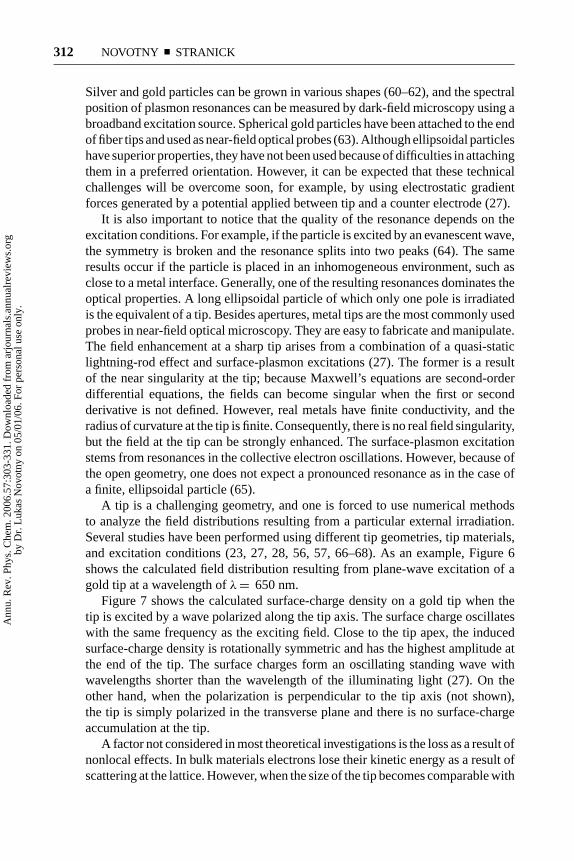
Figure 7 shows the calculated surface-charge density on a gold tip when thetip is excited by a wave polarized along the tip axis. The surface charge oscillateswith the same frequency as the exciting field. Close to the tip apex, the inducedsurface-charge density is rotationally symmetric and has the highest amplitude atthe end of the tip. The surface charges form an oscillating standing wave withwavelengths shorter than the wavelength of the illuminating light (27). On theother hand, when the polarization is perpendicular to the tip axis (not shown),the tip is simply polarized in the transverse plane and there is no surface-chargeaccumulation at the tip.
A factor not considered in most theoretical investigations is the loss as a result ofnonlocal effects. In bulk materials electrons lose their kinetic energy as a result ofscattering at the lattice. However, when the size of the tip becomes comparable with
Ann
u. R
ev. P
hys.
Che
m. 2
006.
57:3
03-3
31. D
ownl
oade
d fr
om a
rjou
rnal
s.an
nual
revi
ews.
org
by D
r. L
ukas
Nov
otny
on
05/0
1/06
. For
per
sona
l use
onl
y.
1 Mar 2006 15:26 AR ANRV272-PC57-11.tex XMLPublishSM(2004/02/24) P1: IKH
SPECTROSCOPY WITH POINTED PROBES 313
Figure 6 Calculated intensity distribution near a laser-irradiated gold tip. The exciting wave
is incident from the left and forms a standing wave pattern as it interferes with the reflected
field from the tip shaft, and at the end of the tip, the wave diffracts. Two different excitation
polarizations are used. The field-enhancement effect is observed only if the incident wave is
polarized along the tip axis (a). In the case of an incident wave polarized perpendicular to
the tip axis, the field near the tip is attenuated (b).
the mean free path of the electrons, there is an increased probability that electronsalso scatter at the interfaces. This scattering leads to increased dissipation and thusto additional damping of the field strength (imaginary part of dielectric constantincreases) (69). These nonlocal effects can be taken into account in a theoreticalanalysis (70, 71), but it is not possible to derive quantitative results because thenonlocal parameters are simply not known.
To gain a more physically intuitive understanding for the optical response ofa metal tip, it is favorable to find an approximate model that can be treated an-alytically. The simplest model for the tip is a quasi-static sphere. As shown inFigure 8, the sphere model is a good approximation if an anisotropic polarizabilitytensor α is used (72). According to this model (see Figure 7b), the external fieldEo oscillating at the angular frequency ω induces a dipole p in the tip accordingto
p(ω) =⎡⎣
α⊥ 0 00 α⊥ 00 0 α‖
⎤⎦ EO (ω),
Ann
u. R
ev. P
hys.
Che
m. 2
006.
57:3
03-3
31. D
ownl
oade
d fr
om a
rjou
rnal
s.an
nual
revi
ews.
org
by D
r. L
ukas
Nov
otny
on
05/0
1/06
. For
per
sona
l use
onl
y.
1 Mar 2006 15:26 AR ANRV272-PC57-11.tex XMLPublishSM(2004/02/24) P1: IKH
314 NOVOTNY � STRANICK
Figure 7 (a) Induced surface-charge density on the surface of a laser-irradiated gold tip
captured at a certain instance of time. Polarization along the tip axis gives rise to a large
surface-charge accumulation at the tip’s apex. The solid line indicates the tip geometry,
whereas the shaded areas represent the surface charge. From Reference 27. (b) Coordinates
used for the dipole model.
where we chose the z-axis to coincide with the tip axis. The transverse polarizabilityα⊥ is identical to the quasi-static polarizability of a small sphere
α⊥(ω) = 4πεor3o
ε(ω) − 1
ε(ω) + 2,
where ro is the tip radius, and ε is the dielectric function of the tip material. Onthe other hand, the longitudinal polarizability α|| is given by
α‖(ω) = 8πεor3o fe(ω),
where fe is the complex field-enhancement factor. For a wavelength ofλ = 830 nm,a gold tip with ε = −24.9 + 1.57i, and a tip radius of ro = 10 nm, our numericalcalculations based on the multiple multipole method (73) lead to fe = −2.9 +11.8i. The expression for a|| originates from the requirement that the magnitude ofthe field produced by p(ω) at the surface of the tip is equal to the computationallydetermined field that we set equal to feEo. The electric field E in the vicinity of thetip is now approximated as
E(r, ω) = Eo(r, ω) + 1
εo
ω2
c2
↔Go(r, ro, ω) p(ω),
where ro specifies the origin of p, and Go is the free space dyadic Green’s function.The tip radius defines how close the dipole can be brought to a sample surface andhow strong the field localization is. Because the external illumination Eo not onlyexcites the metal tip but also irradiates the sample surface, the field enhancement
Ann
u. R
ev. P
hys.
Che
m. 2
006.
57:3
03-3
31. D
ownl
oade
d fr
om a
rjou
rnal
s.an
nual
revi
ews.
org
by D
r. L
ukas
Nov
otny
on
05/0
1/06
. For
per
sona
l use
onl
y.
1 Mar 2006 15:26 AR ANRV272-PC57-11.tex XMLPublishSM(2004/02/24) P1: IKH
SPECTROSCOPY WITH POINTED PROBES 315
Figure 8 Comparison of field distributions (E2) near a gold tip and a gold particle irradiated
by an on-axis focused Hermite-Gaussian (1, 0) laser mode. At the apex of tip the exciting-laser
field is polarized along the tip axis resulting in a longitudinal polarization. The resulting field
is enhanced near the tip apex. The line scans at the bottom represent the field distribution on
a transverse line 1 nm in front of tip and particle, respectively. However, the field distribution
in the case of the metal tip has been scaled by a factor of 0.02. The qualitative agreement
between the field distributions indicates that the tip can be modeled as a particle with a
polarizability that depends on the field-enhancement factor.
needs to be strong enough to suppress the signal associated with direct sampleirradiation.
Noble metals such as gold and silver are highly nonlinear materials that give riseto higher harmonic generation and luminescence when irradiated with laser pulseswith high peak intensity. Nonlinear-signal generation at the apex of a bare metal tipprovides ultrahigh-field localization that is basically background free and suitablefor ultrahigh-resolution imaging (72, 74, 75). By using nonlinear susceptibilities
Ann
u. R
ev. P
hys.
Che
m. 2
006.
57:3
03-3
31. D
ownl
oade
d fr
om a
rjou
rnal
s.an
nual
revi
ews.
org
by D
r. L
ukas
Nov
otny
on
05/0
1/06
. For
per
sona
l use
onl
y.
1 Mar 2006 15:26 AR ANRV272-PC57-11.tex XMLPublishSM(2004/02/24) P1: IKH
316 NOVOTNY � STRANICK
to describe the nonlinear-tip response, the dipole model can be easily extended tothe nonlinear regime (72).
Above we consider a bare metal tip in free space. However, the presence of asample surface will modify the field distribution and hence the field-enhancementfactor. It is straightforward to apply established numerical techniques to study theinfluence of a sample surface. On the other hand, as stated above, an intuitivesimple model is more useful in understanding the physical details.
The dipole model for the tip can be easily extended to account for the presence ofa plane substrate by taking into account the image dipole. Because of the small sizeof the tip and the close proximity to the sample surface, the local field distributioncan be considered in the quasi-static limit; i.e., all the fields in the region of interestoscillate in phase and retardation is ignored. In this limit, Helmholtz’s equationreduces to Laplace’s equation, which is readily solved by the method of images.Consequently, the field above the sample surface can be written as a superpositionof the fields of two dipoles: (a) the field of a tip dipole and (b) the field of theimage dipole located at a distance d + ro below the sample surface, d and ro beingthe tip radius and tip-sample distance, respectively. It is possible to incorporate theinfluence of the image field into an “effective polarizability” according to
p = α[Eo + Eimage] ≡ αeffEo.
Thus, the modification of the local field is equivalent to a modification of the tip’spolarizability. It turns out that the magnitude of the image dipole depends on theorientation of the tip dipole. For the longitudinal component of the field (electricfield in direction of tip axis) one obtains
αeff,‖ = α‖[1 + β]
1 − α‖β/[16πεo(d + ro)3
] , 1 1.
where β represents the quasi-static Fresnel-reflection coefficient defined as
β = εsample − 1
εsample + 1.
Here, εsample is the local-dielectric function of the sample. Similarly, for the trans-verse component (electric field parallel to sample surface) the effective polariz-ability is calculated as
αeff,⊥ = α⊥[1 − β]
1 − α⊥β/[32πεo(d + ro)3
] ,
which is different from the expression for the longitudinal part.The scattering efficiency of the tip depends on the magnitude of the tip dipole
and hence on the effective polarizability. Therefore, the scattered light bears infor-mation on tip-sample distance (d ), the properties of the tip (a), and the propertiesof the sample (b). By keeping d and a constant, variations in scattered intensity asthe tip is scanned over the sample surface can be ascribed to local changes in the
Ann
u. R
ev. P
hys.
Che
m. 2
006.
57:3
03-3
31. D
ownl
oade
d fr
om a
rjou
rnal
s.an
nual
revi
ews.
org
by D
r. L
ukas
Nov
otny
on
05/0
1/06
. For
per
sona
l use
onl
y.
1 Mar 2006 15:26 AR ANRV272-PC57-11.tex XMLPublishSM(2004/02/24) P1: IKH
SPECTROSCOPY WITH POINTED PROBES 317
dielectric constant of the sample εsample. This spectroscopic capability has beendemonstrated by Keilmann, Hillenbrand, and coworkers (33, 76, 77), and theirresults are discussed in the section on scattering-based approaches.
It has to be emphasized that the field enhancement and the scattering efficiencyare interrelated phenomena. Hence, a near-field optical microscope working effi-ciently in local-excitation mode also works efficiently in the local-scattering mode.Finding conditions for a strong local-field enhancement benefits both measurementmodalities.
SCATTERING-BASED APPROACHES
As outlined above, the local-scattering approach in near-field scanning microscopytakes advantage of the nonpropagating evanescent waves present at an irradiatedsample’s surface by using a pointed probe to locally perturb (scatter) these fieldsinto radiation. In this approach, the primary measurable is the field scattered at theapex of the probe and generally at the same wavelength of the incident light. Giventhis, an increase in experimental complexity over standard near-field scanningmicroscopy (NSOM) schemes is required to detect and distinguish between thelocally scattered fields from under the tip (near fields) and the background (far-field) light. The strength of the scattering is dependent on the electromagneticinteraction between the tip and the sample surface. These interactions are governedby the sample’s local-dielectric constant, the probe’s electromagnetic properties,and the probe-sample separation (78). Whereas the nature of the sample systemvaries, one aspect of the experimental system that remains nominally constant isthe tip material. As discussed in the next section, noble metals such as gold provideexcellent scattering efficiencies (17) and the potential for enhanced fields (79), butuseable tips can be fabricated from dielectric and semiconducting materials as well(80, 81).
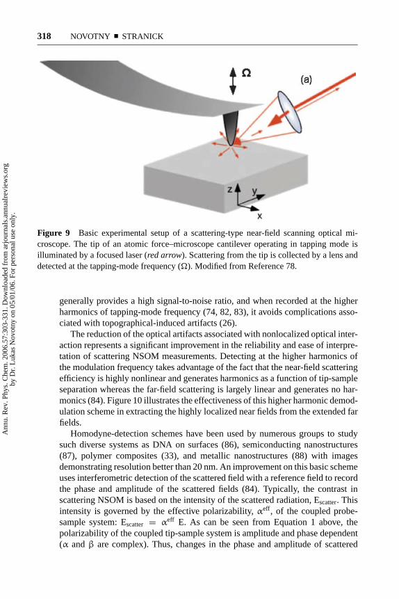
It is useful and instructive to look at some of the common aspects associatedwith scattering NSOM. The basic experimental configuration of the scatteringnear-field scanning optical microscope is shown in Figure 9. The AFM providesa means of maintaining the local scatterer (a metal-coated tip) in the near fieldof the surface: A practical definition of the near field is the region within a probediameter of the sample surface. As the probe is raster-scanned over the surface,the tapping-mode feedback scheme maintains a constant average gap. This allowsone to acquire the topography of the surface while simultaneously recording itsoptical response. Unlike in a conventional tapping-mode AFM, the tapping-modeamplitude (tip-sample separation) is normally set to a value on the order of thespatial extent of the near field. A fast lens is used to collect the scattered light,which is comprised of locally scattered light as well as background scatteringfrom the extended structures of the tip and sample. The local near-field scatter-ing is discriminated from the background scattering using lock-in detection at thetapping-mode frequency, often referred to as homodyne detection. This scheme
Ann
u. R
ev. P
hys.
Che
m. 2
006.
57:3
03-3
31. D
ownl
oade
d fr
om a
rjou
rnal
s.an
nual
revi
ews.
org
by D
r. L
ukas
Nov
otny
on
05/0
1/06
. For
per
sona
l use
onl
y.
1 Mar 2006 15:26 AR ANRV272-PC57-11.tex XMLPublishSM(2004/02/24) P1: IKH
318 NOVOTNY � STRANICK
Figure 9 Basic experimental setup of a scattering-type near-field scanning optical mi-
croscope. The tip of an atomic force–microscope cantilever operating in tapping mode is
illuminated by a focused laser (red arrow). Scattering from the tip is collected by a lens and
detected at the tapping-mode frequency (). Modified from Reference 78.
generally provides a high signal-to-noise ratio, and when recorded at the higherharmonics of tapping-mode frequency (74, 82, 83), it avoids complications asso-ciated with topographical-induced artifacts (26).
The reduction of the optical artifacts associated with nonlocalized optical inter-action represents a significant improvement in the reliability and ease of interpre-tation of scattering NSOM measurements. Detecting at the higher harmonics ofthe modulation frequency takes advantage of the fact that the near-field scatteringefficiency is highly nonlinear and generates harmonics as a function of tip-sampleseparation whereas the far-field scattering is largely linear and generates no har-monics (84). Figure 10 illustrates the effectiveness of this higher harmonic demod-ulation scheme in extracting the highly localized near fields from the extended farfields.
Homodyne-detection schemes have been used by numerous groups to studysuch diverse systems as DNA on surfaces (86), semiconducting nanostructures(87), polymer composites (33), and metallic nanostructures (88) with imagesdemonstrating resolution better than 20 nm. An improvement on this basic schemeuses interferometric detection of the scattered field with a reference field to recordthe phase and amplitude of the scattered fields (84). Typically, the contrast inscattering NSOM is based on the intensity of the scattered radiation, Escatter. Thisintensity is governed by the effective polarizability, αeff, of the coupled probe-sample system: Escatter = αeff E. As can be seen from Equation 1 above, thepolarizability of the coupled tip-sample system is amplitude and phase dependent(α and β are complex). Thus, changes in the phase and amplitude of scattered
Ann
u. R
ev. P
hys.
Che
m. 2
006.
57:3
03-3
31. D
ownl
oade
d fr
om a
rjou
rnal
s.an
nual
revi
ews.
org
by D
r. L
ukas
Nov
otny
on
05/0
1/06
. For
per
sona
l use
onl
y.
1 Mar 2006 15:26 AR ANRV272-PC57-11.tex XMLPublishSM(2004/02/24) P1: IKH
SPECTROSCOPY WITH POINTED PROBES 319
Figure 10 The optical signal amplitudes, DC signal (a), at the tapping-mode fre-
quency (b) and at the second harmonic (c). At the second harmonic, the detected
optical signal is highly localized at the surface, and nonlocalized scattering is virtually
eliminated. From Reference 85.
Ann
u. R
ev. P
hys.
Che
m. 2
006.
57:3
03-3
31. D
ownl
oade
d fr
om a
rjou
rnal
s.an
nual
revi
ews.
org
by D
r. L
ukas
Nov
otny
on
05/0
1/06
. For
per
sona
l use
onl
y.
1 Mar 2006 15:26 AR ANRV272-PC57-11.tex XMLPublishSM(2004/02/24) P1: IKH
320 NOVOTNY � STRANICK
radiation can be related to the complex dielectric constant of the local region ofthe sample surface, εsample: β = (εsample −1)/(εsample + 1). Thus, by acquiring therelative phase and amplitude shifts using interferometric-detection schemes in con-cert with scattering-type NSOM, one can measure or map out the nanometer-scalevariations of heterogeneous materials. An illustration of this is shown in Figure 11.
Figure 11 Scattering-type NSOM images of the topography (a) and the simultane-
ously recorded optical amplitude (b) of a three-component test sample comprised of
gold (Au) and polystyrene (PS) nanostructures on silicon (Si). The accompanying line
scans of the regions detailed by the dashed lines in the image illustrate both the attain-
able resolution and the ability to distinguish between the nanometer-scale components,
Au and PS, of this system. From Reference 89.
Ann
u. R
ev. P
hys.
Che
m. 2
006.
57:3
03-3
31. D
ownl
oade
d fr
om a
rjou
rnal
s.an
nual
revi
ews.
org
by D
r. L
ukas
Nov
otny
on
05/0
1/06
. For
per
sona
l use
onl
y.
1 Mar 2006 15:26 AR ANRV272-PC57-11.tex XMLPublishSM(2004/02/24) P1: IKH
SPECTROSCOPY WITH POINTED PROBES 321
Of importance in these images (recorded at 633 nm) is the unique ability of thisdetection scheme to contrast between different materials based on their dielectricproperties at 633 nm. The measured values for the scattering amplitudes and phaseare in good agreement with those predicted by various models (89).
With the achievable resolution of scattering NSOM below 10 nm, there is aneed to increase the sensitivity or efficiency of the measured signal. This be-comes increasingly important when the sample system is comprised of componentswith similar complex dielectric constants at a given wavelength. One method ofincreasing the signal efficiency is to move to regions in the spectrum contain-ing resonances that further differentiate the materials comprising the sample orthose taking advantage of resonances in the material-comprising tip. In the lattercase, exploiting phonon resonances in common tip materials has shown to be apromising way to improve the efficiency and sensitivity of scattering-type NSOM(77). In the former case, whereas the refractive index of many polymers is es-sentially the same at visible wavelengths, the polymers vary substantially in thevibrational infrared as a result of absorption resonances giving rise to dispersivefeatures in the refractive index via the Kramers-Kronig relations. An exampleof this is shown in Figure 12 where polystyrene inclusions are easily resolved in a
Figure 12 Infrared scattering-type NSOM contrast of polystyrene (PS) inclusions in a
polymethylmetacrylate (PMMA). (a) The calculated and measured contrast as a function of
wavelength. (b) Images of the topography (left) and recorded infrared amplitudes (right).From Reference 90.
Ann
u. R
ev. P
hys.
Che
m. 2
006.
57:3
03-3
31. D
ownl
oade
d fr
om a
rjou
rnal
s.an
nual
revi
ews.
org
by D
r. L
ukas
Nov
otny
on
05/0
1/06
. For
per
sona
l use
onl
y.
1 Mar 2006 15:26 AR ANRV272-PC57-11.tex XMLPublishSM(2004/02/24) P1: IKH
322 NOVOTNY � STRANICK
polymethylmetacrylate continuum based on their refractive index in a vibrationalinfrared region where polymethylmetacrylate has a resonance and polystyrene doesnot. The power of this technique is evident. Operating a scattering near-field scan-ning optical microscope in this spectral region will allow identification of chemicalspecies based on well-documented libraries of far-field infrared-absorption spectrawith spatial resolution below 10 nm (90).
Whereas the results indicate the successful implementation of scattering NSOM,there are certain limitations to address before the full potential of this technique isrealized, such as the inability to acquire information at frequencies other than theincident wavelength. This is a shortcoming that will be addressed by the techniquein the section below.
LOCAL EXCITATION–BASED APPROACHES
The local-excitation scheme allows optical signals to be detected that are spec-trally shifted from the excitation wavelength. In the past, this approach has beenapplied to two-photon excited fluorescence (24), single-photon excited fluores-cence (47, 50, 80, 91), Raman scattering (25, 41–43), and CARS (44). To date,these experiments are performed with metal or semiconducting tips, but in the nearfuture, other geometries with optimized resonant-antenna properties are likely tobe employed (51–53).
The first high-resolution fluorescence images recorded with sharply pointedgold tips were demonstrated in 1999 (24). In these experiments, sample fluores-cence was excited by two-photon absorption using the locally enhanced field atthe tip apex. Fluorescence images with resolution exceeding 30 nm were demon-strated on photosynthetic membranes containing chlorophyll molecules as activefluorophores, and on J-aggregates consisting of strongly coupled pseudoisocyaninedye molecules. These initial experiments purposely made use of a nonlinear-opticalinteraction, such as two-photon absorption, to suppress background fluorescenceassociated with the direct irradiation of the sample surface (recall that the tip isirradiated in the far field). However, the advantage of nonlinear excitation of thesample was diminished by a background luminescence generated in the metaltip: Metals too are highly nonlinear optical materials. To increase the signal-to-noise ratio of near-field fluorescence imaging and to boost the sensitivity downto the single-molecule level, two other strategies have been put forth: (a) furtherreduction of the excitation volume and (b) modulation techniques similar to thoseemployed in the scattering scheme discussed above. The first strategy was pursuedand demonstrated by Guckenberger and coworkers (50, 92). In their approach ametal tip is directly fabricated on the end-face of a standard aperture probe (seeFigure 13a). In this tip-on-aperture (TOA) approach, light emitted by the aperturedirectly couples to the tip and localizes the field at the tip’s apex. This approachovercomes the problem of the far-field background associated with tip irradiationand therefore leads to a higher signal-to-background ratio. The tip of the TOA
Ann
u. R
ev. P
hys.
Che
m. 2
006.
57:3
03-3
31. D
ownl
oade
d fr
om a
rjou
rnal
s.an
nual
revi
ews.
org
by D
r. L
ukas
Nov
otny
on
05/0
1/06
. For
per
sona
l use
onl
y.
1 Mar 2006 15:26 AR ANRV272-PC57-11.tex XMLPublishSM(2004/02/24) P1: IKH
SPECTROSCOPY WITH POINTED PROBES 323
Figure 13 (a) Scanning electron microscopy image of a tip-on-aperture probe consisting
of a SiOx whisker grown directly on an aperture probe. (b) Fluorescence patterns of single
molecules recorded with a tip-on-aperture probe. The centers of all molecules appear dark
because of fluorescence quenching. From Reference 50.
probe shown in Figure13a was fabricated by electron beam–assisted depositionof SiOx. The tip was then cut to the desired length with a focused ion beam andovercoated with aluminum or gold.
Figure 13b shows fluorescence images of single molecules acquired with aTOA probe. Most molecules show up as a two-lobe pattern that results from theprojection of the radially polarized electric field at the tip apex onto the dipoleaxis of the molecules. Interestingly, all fluorescence patterns exhibit a dark center,independent of the orientation of the molecular absorption dipole axis. This is anindication that fluorescence quenching becomes important for short tip-moleculedistances (93, 94).
The tradeoff between fluorescence quenching and field enhancement is stillbeing investigated. Different theoretical models have been developed (95–100),and experimental results are often inconsistent (47, 50, 80, 81, 91, 94, 101). Thisinconsistency originates from the fact that an excited molecule located near ametal structure (such as a tip) will relax to its ground state through radiative decay(γr ) and nonradiative decay (γnr). In the presence of a pointed probe, both decayrates can be significantly increased over the free-space decay rate (γo) (100, 101).However, as long as γnr is much larger than γr , fluorescence will be quenched.For excitation intensities below saturation, the emitted fluorescence rate can bewritten as
γem(ω) = γexc[1 − γnr/γ],
where γ exc ∼ E2 is the excitation rate. The expression in the brackets correspondsto the apparent quantum yield qa = γr/γ , γ = γnr + γr represents the totaldecay rate. The individual rates γ i depend on probe shape and material, and on the
Ann
u. R
ev. P
hys.
Che
m. 2
006.
57:3
03-3
31. D
ownl
oade
d fr
om a
rjou
rnal
s.an
nual
revi
ews.
org
by D
r. L
ukas
Nov
otny
on
05/0
1/06
. For
per
sona
l use
onl
y.
1 Mar 2006 15:26 AR ANRV272-PC57-11.tex XMLPublishSM(2004/02/24) P1: IKH
324 NOVOTNY � STRANICK
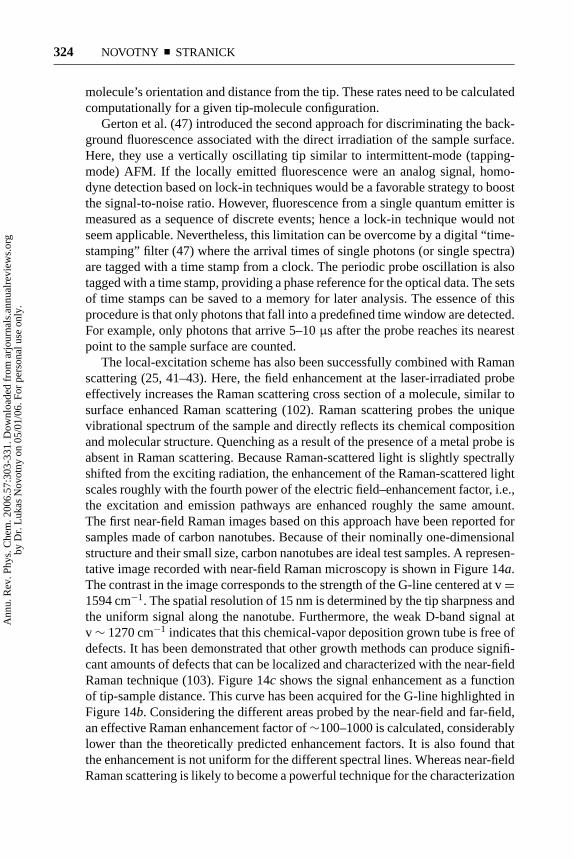
molecule’s orientation and distance from the tip. These rates need to be calculatedcomputationally for a given tip-molecule configuration.
Gerton et al. (47) introduced the second approach for discriminating the back-ground fluorescence associated with the direct irradiation of the sample surface.Here, they use a vertically oscillating tip similar to intermittent-mode (tapping-mode) AFM. If the locally emitted fluorescence were an analog signal, homo-dyne detection based on lock-in techniques would be a favorable strategy to boostthe signal-to-noise ratio. However, fluorescence from a single quantum emitter ismeasured as a sequence of discrete events; hence a lock-in technique would notseem applicable. Nevertheless, this limitation can be overcome by a digital “time-stamping” filter (47) where the arrival times of single photons (or single spectra)are tagged with a time stamp from a clock. The periodic probe oscillation is alsotagged with a time stamp, providing a phase reference for the optical data. The setsof time stamps can be saved to a memory for later analysis. The essence of thisprocedure is that only photons that fall into a predefined time window are detected.For example, only photons that arrive 5–10 μs after the probe reaches its nearestpoint to the sample surface are counted.
The local-excitation scheme has also been successfully combined with Ramanscattering (25, 41–43). Here, the field enhancement at the laser-irradiated probeeffectively increases the Raman scattering cross section of a molecule, similar tosurface enhanced Raman scattering (102). Raman scattering probes the uniquevibrational spectrum of the sample and directly reflects its chemical compositionand molecular structure. Quenching as a result of the presence of a metal probe isabsent in Raman scattering. Because Raman-scattered light is slightly spectrallyshifted from the exciting radiation, the enhancement of the Raman-scattered lightscales roughly with the fourth power of the electric field–enhancement factor, i.e.,the excitation and emission pathways are enhanced roughly the same amount.The first near-field Raman images based on this approach have been reported forsamples made of carbon nanotubes. Because of their nominally one-dimensionalstructure and their small size, carbon nanotubes are ideal test samples. A represen-tative image recorded with near-field Raman microscopy is shown in Figure 14a.The contrast in the image corresponds to the strength of the G-line centered at v =1594 cm−1. The spatial resolution of 15 nm is determined by the tip sharpness andthe uniform signal along the nanotube. Furthermore, the weak D-band signal atv ∼ 1270 cm−1 indicates that this chemical-vapor deposition grown tube is free ofdefects. It has been demonstrated that other growth methods can produce signifi-cant amounts of defects that can be localized and characterized with the near-fieldRaman technique (103). Figure 14c shows the signal enhancement as a functionof tip-sample distance. This curve has been acquired for the G-line highlighted inFigure 14b. Considering the different areas probed by the near-field and far-field,an effective Raman enhancement factor of ∼100–1000 is calculated, considerablylower than the theoretically predicted enhancement factors. It is also found thatthe enhancement is not uniform for the different spectral lines. Whereas near-fieldRaman scattering is likely to become a powerful technique for the characterization
Ann
u. R
ev. P
hys.
Che
m. 2
006.
57:3
03-3
31. D
ownl
oade
d fr
om a
rjou
rnal
s.an
nual
revi
ews.
org
by D
r. L
ukas
Nov
otny
on
05/0
1/06
. For
per
sona
l use
onl
y.
1 Mar 2006 15:26 AR ANRV272-PC57-11.tex XMLPublishSM(2004/02/24) P1: IKH
SPECTROSCOPY WITH POINTED PROBES 325
Figure 14 Near-field Raman imaging of single-walled carbon nanotubes (a). This im-
age was recorded by raster-scanning the sample underneath a laser-irradiated metal tip and
integrating, for each image pixel, the photon counts that fall into a narrow spectral band-
width centered around the G-line at v = 1594 cm−1 (indicated by the yellow stripe in b).
(b) Raman-scattering spectrum recorded on top of the nanotube. (c) Enhancement of the
G-line signal as a function of tip-sample distance. The yellow line is an exponential fit with
a 13-nm decay length.
of defects and dopants in nanotubes, the enhancement is currently too weak forapplications in biology. Thus, future work must be aimed at optimizing the fieldenhancement by exploring finite-sized geometries inspired by classical antennatheory (51–53).
Near-field vibrational spectroscopy has recently been extended to the nonlinearregime by Kawata and coworkers (44). This group used near-field CARS to imageclusters of DNA with contrast corresponding to the ring-breathing mode of diazoleof adenine molecules. It can be expected that near-field CARS microscopy willfind interesting applications in biological nanoscience similar to those currentlystudied by confocal CARS microscopy (104).
Metals are highly nonlinear-optical materials. Because of their small skin depth,the nonlinearity mainly enters through a nonlinear-surface susceptibility (105).Therefore, when a pointed metal probe is irradiated with laser pulses of a highpeak intensity, different nonlinear-optical responses can be observed. The emittedspectrum shows peaks that can be assigned to second-harmonic generation, third-harmonic generation, sum-frequency generation, difference-frequency generation,and four-wave mixing. These spectral lines are generated by the enhanced fieldat the tip’s apex; hence they constitute a highly confined photon source suitablefor localized interactions with the sample surface. More importantly, the intensityof the spectral lines can be influenced by local electronic or vibrational sampleresonances. This holds promise for the development of near-field extinction spec-troscopy aimed at measuring the local polarizability of the sample.
Ann
u. R
ev. P
hys.
Che
m. 2
006.
57:3
03-3
31. D
ownl
oade
d fr
om a
rjou
rnal
s.an
nual
revi
ews.
org
by D
r. L
ukas
Nov
otny
on
05/0
1/06
. For
per
sona
l use
onl
y.
1 Mar 2006 15:26 AR ANRV272-PC57-11.tex XMLPublishSM(2004/02/24) P1: IKH
326 NOVOTNY � STRANICK
CONCLUSION
Overall, research in the area of near-field microscopy and spectroscopy withpointed probes has produced promising results. It is evident that the local scatteringand local excitation at a pointed probe holds promise for high-resolution chemicaland materials characterization at finer length scales. As with other near-field meth-ods, materials and sample systems with extended complexity in the z dimensioncomplicate the straightforward analysis of NSOM images (85). This limits thepresent application of these techniques to thin-film samples with a thickness onthe order of the near field, probe diameter, or to systems that are homogeneous inthe z dimension. Other challenges reside in the development of improved probestructures and in the development of a physical understanding of the factors dic-tating the spectral response of complex, heterogeneous nanometer-scale systems.
ACKNOWLEDGMENTS
We acknowledge financial support from the U.S. Department of Energy (Grant DE-FG02-01ER15204) and from the Air Force Office for Scientific Research throughthe Multidisciplinary University Research Initiative (Grant F-49620-03-1-0379).
The Annual Review of Physical Chemistry is online athttp://physchem.annualreviews.org
LITERATURE CITED
1. Pohl DW, Denk W, Lanz M. 1984. Optical
stethoscopy: image recording with resolu-
tion λ/20. Appl. Phys. Lett. 44:651–53
2. Lewis A, Isaacson M, Harootunian A,
Muray A. 1984. Development of a 500-
A spatial-resolution light-microscope. Ul-tramicroscopy 13:227–31
3. Dunn RC. 1999. Near-field scanning opti-
cal microscopy. Chem. Rev. 99:2891–927
4. Paesler MA, Moyer PJ. 1996. Near-FieldOptics: Theory, Instrumentation, and Ap-plications. New York: Wiley Interscience
5. Fillard JP. 1996. Near-Field Optics andNanoscopy. Singapore: World Scientific
6. Kawata S, Ohtus M, Irie M. 2002. Nano-Optics. New York: Springer Verlag
7. Prasad PN. 2004. Nanophotonics. New
York: Wiley Interscience
8. Courjon D. 2003. Near Field Microscopyand Near Field Optics. London: Imperial