Nanotribology of nacre: Anisotropic dissipation in a multiscale hybrid material Philippe Stempfle ´ a,n , Xavier Bourrat b , Marthe Rousseau c , Evelyne Lopez d , Jamal Takadoum a a Institut FEMTO–ST (UMR CNRS 6174 – Universite de Franche Comte – CNRS – ENSMM – UTBM), ENSMM 26 Chemin de l’Epitaphe, F–25030 Besancon Cedex, France b Orleans University CNRS ISTO, 1A Rue de Ferollerie, 45071 Orleans Cedex 2, France c Nancy University (UMR CNRS 7561), 9 Avenue de la Foret de Haye, 54505 Vandoeuvre les Nancy, France d Museum National d’Histoire Naturelle (UMR 5178 CNRS – MNHN), CP 51, 55 Rue Buffon, 75005 Paris, France article info Article history: Received 23 October 2011 Received in revised form 17 September 2012 Accepted 21 September 2012 Available online 7 October 2012 Keywords: Mother of pearl Biocrystal Strength Organic matrix abstract Sheet nacre (so-called mother–of–pearl) is a hybrid biocomposite with a multiscale structure including nanograins of calcium carbonate (97 wt%–40 nm in size) and two organic matrices: (i) the ‘‘intracrystal- line’’ (mainly composed by silk-fibroin-like proteins), and (ii) the ‘‘interlaminar’’ one (mainly composed of b-chitin and proteins). Micro/nanotribological behaviour was investigated on sheet nacre displaying various configurations (so-called face-on and edge-on), by varying the orientation of the matrices vs. the sliding direction. Different levels of frictional dissipated energy were observed as a function of both: (i) the type of matrix which is involved in the dissipation mechanism (intracrystalline or interlaminar), and (ii) the orientation of the matrices themselves vs. the sliding direction. These various dissipative ways can involve either, multiscale wear processes entailing the both matrices, or irreversible deformation only, without any wear process. They have been identified and explained by considering the double composite structure of sheet nacre. & 2012 Elsevier Ltd. All rights reserved. 1. Introduction Sheet nacre (the pearly internal layer of molluscan shells) is a hybrid biocomposite with a multiscale structure including nanograins of calcium carbonate (97 wt%) [1–3] and two organic matrices (3 wt%) [3–5]. At the nanoscale, biocrystals (ca 40 nm in size) are drowned in an ‘‘intracrystalline’’ organic matrix (4 nm thick) in order to form a microsized flat organomineral aragonite tablet (thickness about 500 nm) [6–9]. At a larger scale [10–14], these tablets are themselves surrounded by a porous ‘‘interlami- nar’’ organic matrix (thickness: 40 nm, porosity in-between 35% and 59%) building up a material displaying highly interesting properties [15–21]: low density, good biocompatibility [22–25] and osteogenic properties for human bone regeneration [22,26–28]. Thus, this material is currently being studied as small prostheses (e.g. rachis and dorsal vertebra prostheses, which are both subjected to micro-slip and fretting wear), or for the creation of new organic/ inorganic bio-inspired hybrid materials [29–35]. Recently, friction and wear behaviour of sheet nacre were studied in dry friction [36–39] and in liquid medium [36], respectively. Results have shown that: (i) the environment strongly influences the wear mechanisms of nacre by means of various physico-chemical interactions on the water-soluble ‘‘intracrystalline’’ organic phase [36]; (ii) the energy absorption ability of the matrix is drastically reduced in presence of nanoshocks generated during friction by the dynamic solicitations. As a result, cracks migrate in the tablet involving the formation of wear nano-debris [37]; (iii) at high mean contact pressure, additional thermal-induced wear damage involves the degradation of the organic matrices, that increases dramatically the wear rate of nacre [38–40]; Thus, for this kind of solicitations, nacre is clearly subjected to peculiar thermal [38,41] and mechanical [36,37] damage pro- cesses, which occur at two order of magnitude, involving its double composite structure—i.e. both organic matrices are always directly involved in the friction-induced energy dissipation mechanisms [42–48] and in the subsequent damage mechanisms, as well [42, 49–53]. So, the orientation of the tablets [14,54] – and especially the one of the matrices themselves—with respect to the sliding direction seems to be a key parameter for understanding the Contents lists available at SciVerse ScienceDirect journal homepage: www.elsevier.com/locate/triboint Tribology International 0301-679X/$ - see front matter & 2012 Elsevier Ltd. All rights reserved. http://dx.doi.org/10.1016/j.triboint.2012.09.010 n Corresponding author. Tel.: þ33 3 81 40 27 64; fax: þ33 3 81 40 28 52. E-mail addresses: philippe.stempfl[email protected], philippe.stempfl[email protected] (P. Stempfle ´). Tribology International 63 (2013) 250–264
Transcript
Tribology International 63 (2013) 250–264
Contents lists available at SciVerse ScienceDirect
Nanotribology of nacre: Anisotropic dissipation in a multiscalehybrid material
Philippe Stempfle a,n, Xavier Bourrat b, Marthe Rousseau c, Evelyne Lopez d, Jamal Takadoum a
a Institut FEMTO–ST (UMR CNRS 6174 – Universite de Franche Comte – CNRS – ENSMM – UTBM), ENSMM 26 Chemin de l’Epitaphe, F–25030 Besancon Cedex, Franceb Orleans University CNRS ISTO, 1A Rue de Ferollerie, 45071 Orleans Cedex 2, Francec Nancy University (UMR CNRS 7561), 9 Avenue de la Foret de Haye, 54505 Vandoeuvre les Nancy, Franced Museum National d’Histoire Naturelle (UMR 5178 CNRS – MNHN), CP 51, 55 Rue Buffon, 75005 Paris, France
a r t i c l e i n f o
Article history:
Received 23 October 2011
Received in revised form
17 September 2012
Accepted 21 September 2012Available online 7 October 2012
Sheet nacre (so-called mother–of–pearl) is a hybrid biocomposite with a multiscale structure including
nanograins of calcium carbonate (97 wt%–40 nm in size) and two organic matrices: (i) the ‘‘intracrystal-
line’’ (mainly composed by silk-fibroin-like proteins), and (ii) the ‘‘interlaminar’’ one (mainly composed
of b-chitin and proteins). Micro/nanotribological behaviour was investigated on sheet nacre displaying
various configurations (so-called face-on and edge-on), by varying the orientation of the matrices vs. the
sliding direction. Different levels of frictional dissipated energy were observed as a function of both:
(i) the type of matrix which is involved in the dissipation mechanism (intracrystalline or interlaminar),
and (ii) the orientation of the matrices themselves vs. the sliding direction. These various dissipative
ways can involve either, multiscale wear processes entailing the both matrices, or irreversible
deformation only, without any wear process. They have been identified and explained by considering
the double composite structure of sheet nacre.
& 2012 Elsevier Ltd. All rights reserved.
1. Introduction
Sheet nacre (the pearly internal layer of molluscan shells) isa hybrid biocomposite with a multiscale structure includingnanograins of calcium carbonate (97 wt%) [1–3] and two organicmatrices (3 wt%) [3–5]. At the nanoscale, biocrystals (ca 40 nm insize) are drowned in an ‘‘intracrystalline’’ organic matrix (4 nmthick) in order to form a microsized flat organomineral aragonitetablet (thickness about 500 nm) [6–9]. At a larger scale [10–14],these tablets are themselves surrounded by a porous ‘‘interlami-
nar’’ organic matrix (thickness: 40 nm, porosity in-between 35%and 59%) building up a material displaying highly interestingproperties [15–21]: low density, good biocompatibility [22–25]and osteogenic properties for human bone regeneration [22,26–28].Thus, this material is currently being studied as small prostheses(e.g. rachis and dorsal vertebra prostheses, which are both subjectedto micro-slip and fretting wear), or for the creation of new organic/inorganic bio-inspired hybrid materials [29–35].
All rights reserved.
x: þ33 3 81 40 28 52.
Recently, friction and wear behaviour of sheet nacre were studiedin dry friction [36–39] and in liquid medium [36], respectively.Results have shown that:
�
(i) the environment strongly influences the wear mechanismsof nacre by means of various physico-chemical interactions onthe water-soluble ‘‘intracrystalline’’ organic phase [36]; � (ii) the energy absorption ability of the matrix is drastically
reduced in presence of nanoshocks generated during frictionby the dynamic solicitations. As a result, cracks migrate in thetablet involving the formation of wear nano-debris [37];
� (iii) at high mean contact pressure, additional thermal-induced
wear damage involves the degradation of the organic matrices,that increases dramatically the wear rate of nacre [38–40];
Thus, for this kind of solicitations, nacre is clearly subjected topeculiar thermal [38,41] and mechanical [36,37] damage pro-cesses, which occur at two order of magnitude, involving its doublecomposite structure—i.e. both organic matrices are always directlyinvolved in the friction-induced energy dissipation mechanisms[42–48] and in the subsequent damage mechanisms, as well [42,49–53]. So, the orientation of the tablets [14,54] – and especially theone of the matrices themselves—with respect to the slidingdirection seems to be a key parameter for understanding the
P. Stempfle et al. / Tribology International 63 (2013) 250–264 251
dissipation mechanisms of sheet nacre under dynamic solicitations,as met in tribological tests. Indeed, anisotropic specificities of sheetnacre under quasi-static solicitations—- (i.e.), tension [15,49,55,56],three- and four-point bending [44], shear [44,57], micro- [56–59]and nano-indentation [37,53,60–63]) have been actively studied ormodelled [45,54] in the past. But, up to now, tribological resultshave been achieved with a face-on configuration sheet nacre only[36–39] – i.e. when the tablets are oriented more or less parallel tothe friction direction—leaving the study of the real influence of thetablets orientation on the wear mechanisms not investigated yet.
This work aims to compare friction and wear mechanisms of sheetnacre cut with a face-on and a edge-on configurations, respectively, inorder to understand how the orientations of the organic phases vs. thesliding direction can change the ways to dissipate the frictional energy.In order to avoid any additional thermal effects, and to better controlthe environment around the contact, tribological tests have beencarried out under low contact pressures, by using a multi-asperitynanotribometer [64–66] working in an environmental glove box.
2. Experimental part
2.1. Samples
Samples are made of dry sheet nacre extracted from giant oysterPinctada maxima [3,4,6–8,36,67] cut with a face-on andedge-on
Fig. 1. Various configurations of the samples: (a) face-on orientation; (b) edge-on
perpendicular to the sliding direction, and (c) edge-on parallel to the sliding direction.
Table 1Mechanical properties of elemental components of dry shee
a Assessed by sharp nanoindentation test [62].b Computed by a Mori-Tanaka model [62].c Computed by a Hertzian model [62].d Assessed by combining acoustic microscopy and sphe
configuration, respectively (Fig. 1). Surfaces are polished with aRMS roughness about 14.570.6 nm. Three configurations have beentested with respect to the direction of sliding:
�
t na
)
(5.67
.79)
.41)
rica
a face-on configuration parallel to the direction of sliding (Fig. 1a);
� an edge-on configuration perpendicular to the direction of sliding
(Fig. 1b);
� an edge-on configuration parallel to the direction of sliding
(Fig. 1c);
As mentioned earlier, this type of sheet nacre has a multiscalestructure [3,68,69]:
�
On the one hand, aragonite tablets (500 to 700 nm thick) aresurrounded by an ‘‘interlaminar’’ thin network (about 40 nm thick)of a biological porous organic adhesive (average porosity 49712%[63]]) mainly composed of b-chitin and proteins [10–13]. � On the other hand, each aragonite tablet is constituted by
nanosized biocrystals of CaCO3 surrounded by a water-soluble‘‘intracrystalline’’ organic phase (mainly silk-fibroin-like pro-teins) organised as a foam with very thin walls and closedporosity (4 nm) [3,4,6–8,36]. The average size of these initialbiocrystals is about 38721 nm [62].
In addition, mechanical properties of each component—i.e. bio-crystals and organic matrices—have previously been assessed byusing SEM analysis, acoustic microscopy [63,70], spherical andsharp nanoindentation tests [37,60,62], combined with multiscalenumerical simulations using FEM [37,39] and homogenisationapproach [62]. Main mechanical features are reported in Table 1.The mechanical properties of the ‘‘interlamellar’’ matrix are veryclose to the ones determined by Xu et al. [71] using more localassessments.
2.2. Nanotribological setup
2.2.1. In situ friction assessment
The experimental device (Fig. 2a) is constituted by a ball-on-disc
nanotribometer manufactured by CSM Instruments (Switzerland)
[66,72]. A pin is mounted on a stiff lever, designed as a frictionlessforce transducer ðKx ¼ 265:1 N m�1; Kz ¼ 152:2 Nm�1
Þ. The frictionforce is determined during the test by measuring the deflectionof the elastic arm (low load range down to 50 mN). The ball(Si3N4�1:5 mmÞ is loaded onto a flat nacre sample with a preciselyknown force using closed loop. The load and friction resolutions areabout 1 mN. Tribological tests are carried out in linear reciprocatingmode at room temperature (22 1C) under ambient air (RH 35%), inan environmental glove box. The normal load varies from 10 to80 mN corresponding to a contact pressure varying from 0.15 to0.65 GPa. The stroke frequency, the stroke length and the strokelength resolution are respectively 10 Hz, 70.5 mm, and 250 nm.The velocity and the sliding distance are respectively 1 mm s�1 and0.2 m, corresponding to 100 cycles in order to reach the steady statein friction.
cre.
n sy (GPa)
)a 0.17 (0.05)b 13.4 (2.1)c
d 0.29 (1.7e�3) 0.118 (0.02)b 0.296 (1.4e-3)b –
l nanoindentation test [63].
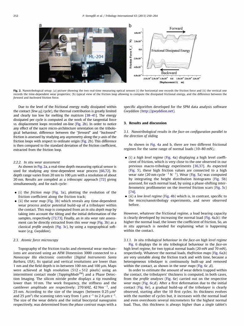
Fig. 2. Nanotribological setup: (a) picture showing the two real-time measuring optical sensors (i) the horizontal one records the friction force and (ii) the vertical one
records the time-dependent wear properties; (b) typical view of the friction loop allowing to compute the dissipated frictional energy, and the difference between the
forward and backward friction force.
P. Stempfle et al. / Tribology International 63 (2013) 250–264252
Due to the level of the frictional energy really dissipated withinthe contact (few mJ=cycle), the thermal contribution is greatly limitedand clearly too low for melting the matrices [38–41]. The energydissipated per cycle is computed as the work of the tangential forcevs. displacement loops recorded on-line (Fig. 2b). In order to noticeany effect of the nacre micro-architecture orientation on the tribolo-gical behaviour, difference between the ‘‘forward’’ and ‘‘backward’’friction is assessed by studying any asymmetry along the y-axis of thefriction loops with respect to ordinate origin (Fig. 2b). This differenceis then compared to the standard deviation of the friction coefficient,extracted from the friction loop.
2.2.2. In situ wear assessment
As shown in Fig. 2a, a real-time depth measuring optical sensor isused for studying any time-dependent wear process [66,72]. Itsdepth range varies from 20 nm to 100 mm with a resolution of about20 nm. Results are compiled as a triboscopic approach [72] givingsimultaneously, and for each cycle:
�
(i) the friction map (Fig. 3a), plotting the evolution of thefriction coefficient along the friction track; � (ii) the wear map (Fig. 3b) which reveals any time-dependent
wear process and/or potential build-up of a tribolayer withinthe contact. This map is computed from an in situ depth map bytaking into account the tilting and the initial deformation of thesamples, respectively [72,73]. Finally, an in situ wear rate assess-ment can be directly extracted from this wear map (Fig. 3b) as aclassical profile analysis (Fig. 3c), by using a topographical soft-ware (e.g. Gwyddion).
2.3. Atomic force microscopy
Topography of the friction tracks and elemental wear mechan-isms are assessed using an AFM Dimension 3000 connected to aNanoscope IIIa electronic controller (Digital Instruments Santa
Barbara, USA). Its spatial and vertical resolutions are lower than1 nm and the field depth is in-between 100 nm and 100 mm. Mapswere achieved at high resolution (512�512 pixels) using anintermittent contact mode (TappingModeTM) and a Phase Detec-tion Imaging. The silicon nitride probe displays a tip roundinglower than 10 nm. The work frequency, the stiffness and thecantilever amplitude are respectively: 270 kHZ, 42 Nm�1, and25 nm. According to the size of the images (between 0:25 mm2
and 25 mm2Þ the scanning rates vary from 1 mm s�1 to 2:4 mm s�1.The size of the wear debris and the initial biocrystal nanograinsrespectively, was determined from the phase contrast maps with a
specific algorithm developed for the SPM data analysis softwareGwyddion (http://gwyddion.net).
3. Results and discussion
3.1. Nanotribological results in the face-on configuration parallel to
the direction of sliding
As shown in Fig. 4a and b, there are two different frictionalregimes for the same range of normal loads (10–80 mN),:
�
(i) a high level regime (Fig. 4a) displaying a high level coeffi-cient of friction, which is very close to the one observed in ourprevious macro-tribology experiments [36,37]. As expected(Fig. 5), these high friction values are connected to a highwear rate (20 nm cycle�1 N�1). Wear (Fig. 5a) was computedby integrating the height distribution histograms (Fig. 5b)assessed, for each normal load, by using a phase-shifting inter-ferometric profilometer on the inverted friction scars (Fig. 5c)[74]. � (ii) a low level regime (Fig. 4b) which is, in contrast, specific to
the micro/nanotribology experiments, and never observedbefore.
However, whatever the frictional regime, a load bearing capacityis clearly developed by increasing the normal load (Fig. 4a,b): thehigher the normal load, the lower the coefficient of friction. So, anin situ approach is needed for explaining what is happeningwithin the contact.
3.1.1. In situ tribological behaviour in the face-on high level regime
Fig. 6 displays the in situ tribological behaviour in the face-on
high level regime, for two typical normal loads (20 mN and 70 mN),respectively. Whatever the normal loads, thefriction maps (Fig. 6a,b)are very unstable along the friction track and with time, because aheterogeneous tribolayer is continuously built-up and removedwithin the contact, as shown in the wear maps (Fig. 6c ,d).
In order to estimate the amount of wear debris trapped withinthe contact, the tribolayers’ thickness is computed, in both cases,from the profile analyses (Fig. 6e) carried out on the respectivewear maps (Fig. 6c,d). After a first deformation due to the initialcontact (Fig. 6e), a gradual build-up of the tribolayer is clearlyobserved, starting after the 10 first cycles. Its thickness evolveswith the number of cycles but, it increases with the normal loadand even overshoots several micrometers for the highest normalload. Thus, this thickness is always higher than a single tablet’s
Fig. 4. Evolution of the coefficient of friction with the normal load in the face-on configuration: (a) high level regime and (b) low level regime.
Fig. 3. Typical views resulting from the in situ triboscopic approach giving simultaneously and for each cycle: (a) the evolution of the friction coefficient along the friction
track (friction map); (b) the evolution of the time-dependent wear process and/or potential build-up of a tribolayer within the contact (wear map); and (c) the in situ wear
rate assessment by using a classical profile analysis.
P. Stempfle et al. / Tribology International 63 (2013) 250–264 253
thickness (about 500 nm), revealing that several layers of tabletsare probably involved in the wear process. Besides, successivejumps and drops observed on the wear profile (Fig. 6e) are alwaysin the same order of magnitude as the tablets’ thickness, suggest-ing some tablets’ movement under the slider: hence, pieces oftablets are directly involved by the wear mechanism. As a result,the amount of the wear debris trapped within the contact is very
important and so, the size of the wear debris itself, as reported inthe typical SEM views after sliding (Fig. 7).
�
For the lowest load (Fig. 7a), the contact occurs mainly on thefirst bodies. The size of the huge debris clearly involves thecracking of tablets and so, the fracturing of the ‘‘interlaminar’’organic matrix as a main wear mechanism.
Fig. 6. In situ tribological behaviour in the face-on high level regime for two applied normal loads: (a) friction maps at 20 mN and (b) at 70 mN; (c) wear maps at 20 mN, and
(d) at 70 mN; (e) corresponding in situ wear profile assessment carried out in the centre of the friction track.
Fig. 5. Wear assessment in the face-on high level regime: for each applied normal load, wear (a) is computed by integration of the height distribution histograms (b) from
the topographical features of the inverted friction scar (c).
P. Stempfle et al. / Tribology International 63 (2013) 250–264254
�
For the highest normal load (Fig. 7b,c), the tribolayer appearsmore continuous due to a much more important amount ofdebris. In addition to the initial tablets’ fracturing, the wear
behaviour involves the crushing of the initial huge debris(Fig. 7b). Hence, their progressive compaction as a continuoustribolayer (Fig. 7c) is probably connected to the development
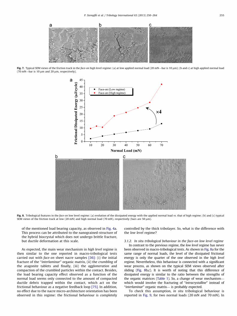
Fig. 7. Typical SEM views of the friction track in the face-on high level regime: (a) at low applied normal load (20 mN—bar is 10 mm); (b and c) at high applied normal load
(70 mN—bar is 10 mm and 20 mm, respectively).
Fig. 8. Tribological features in the face-on low level regime: (a) evolution of the dissipated energy with the applied normal load vs. that of high regime; (b) and (c) typical
SEM views of the friction track at low (20 mN) and high normal load (70 mN), respectively (bars are 50 mm).
P. Stempfle et al. / Tribology International 63 (2013) 250–264 255
of the mentioned load bearing capacity, as observed in Fig. 4a.This process can be attributed to the nanograined-structure ofthe hybrid biocrystal which does not undergo brittle fracture,but ductile deformation at this scale.
As expected, the main wear mechanism in high level regime isthen similar to the one reported in macro-tribological testscarried out with face-on sheet nacre samples [36]: (i) the initialfracture of the ‘‘interlaminar’’ organic matrix, (ii) the crumbling ofthe aragonite tablets and finally, (iii) the agglomeration andcompaction of the crumbled particles within the contact. Besides,the load bearing capacity effect observed as a function of thenormal load seems only connected to the amount of compactedductile debris trapped within the contact, which act on thefrictional behaviour as a negative feedback loop [75]. In addition,no effect due to the nacre micro-architecture orientation has beenobserved in this regime: the frictional behaviour is completely
controlled by the thick tribolayer. So, what is the difference withthe low level regime?
3.1.2. In situ tribological behaviour in the face-on low level regime
In contrast to the previous regime, the low level regime has neverbeen observed in macro-tribological tests. As shown in Fig. 8a for thesame range of normal loads, the level of the dissipated frictionalenergy is only the quarter of the one observed in the high level
regime. Nevertheless, this behaviour is connected with a significantwear process, as shown on the typical SEM views observed aftersliding (Fig. 8b,c). It is worth of noting that this difference ofdissipated energy is similar to the ratio between the strengths ofthe organic matrices (Table 1). So, a change of wear mechanism—
which would involve the fracturing of ‘‘intracrystalline’’ instead of‘‘interlaminar’’ organic matrix— is probably expected.
To check this assumption, in situ tribological behaviour isreported in Fig. 9, for two normal loads (20 mN and 70 mN). In
Fig. 9. In situ tribological behaviour in the face-on low level regime, for two applied normal loads: (a) friction maps at 20 mN, and (b) at 70 mN; (c) wear maps at 20 mN, and
(d) at 70 mN. (e) Comparison of the particles size distribution curves of wear debris with that of nanograins in the initial biocrystal.
P. Stempfle et al. / Tribology International 63 (2013) 250–264256
contrast to what is observed in high level regime (Fig. 6), friction
maps are very smooth along the friction track and with time,whatever the normal load (Fig. 9a,b). Similarly, wear maps are alsoquite homogeneous and reveal that cohesive tribolayers arecontinuously built-up during the test (Fig. 9c,d). They are neverremoved during the tests, in contrast to what is observed for thehigh level regime (Fig. 6). The cohesion ability of tribolayers beinggenerally linked to the size of the elemental wear debris whichconstitute them [75], AFM image analysis (Fig. 9e) confirms thatthis size is very close to the one of the initial biocrystals.
Wear profiles (Fig. 10a) extracted from wear maps (9c and d)also confirm the presence of a very thin tribolayers whosethicknesses are never over the initial tablet’s thickness (above500 nm). That means that only one layer of tablets is here involvedin the wear process. This result is also observed on typical SEMviews (Fig. 10b).
Thus, in face-on low level regime, the wear mechanism would bemainly a fracturing within the tablet involving the ‘‘intracrystalline’’organic matrix only. That would explain the reduction of the fric-tional dissipated energy mentioned earlier (Fig. 8a). Besides, this wear
mechanism is clearly observed after sliding, on typical SEM (Fig. 10c)and AFM views (Fig. 10d), which both reveal the crumbling of thetablets instead of a clear cutting (Fig. 7a). This observation is also ingood agreement with the distribution of wear debris’ size (Fig. 9e). So,the main wear mechanism is due here to a detachment of initialbiocrystals from the top row of tablets by breaking of the ‘‘intracrys-
talline’’ organic matrix. However, why are there two frictional levels inthis face-on configuration?
3.1.3. Transition from low to high level regime
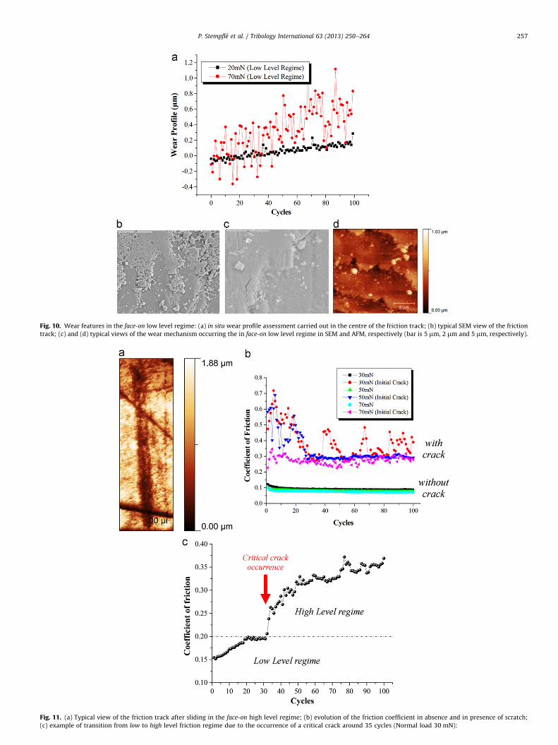
Typical profilometrical view of the friction track after thesliding test (Fig. 11a) reveals that thehigh level regime is alwaysobserved when the friction track has passed through an initialscratch, deeper than the tablets’ thickness. In order to check thisassumption, tribological behaviour of initially scratched surfacesis compared to the one of virgin surfaces (Fig. 11b). As expected,whatever the normal load, the coefficient of friction stronglyincreases and stays at the high level in presence of an initialscratch. Thus, in face-on configuration, friction and wear appearvery sensitive to the track smoothness, as shown in Fig. 11c. As
Fig. 10. Wear features in the face-on low level regime: (a) in situ wear profile assessment carried out in the centre of the friction track; (b) typical SEM view of the friction
track; (c) and (d) typical views of the wear mechanism occurring the in face-on low level regime in SEM and AFM, respectively (bar is 5 mm, 2 mm and 5 mm, respectively).
Fig. 11. (a) Typical view of the friction track after sliding in the face-on high level regime; (b) evolution of the friction coefficient in absence and in presence of scratch;
(c) example of transition from low to high level friction regime due to the occurrence of a critical crack around 35 cycles (Normal load 30 mN):
P. Stempfle et al. / Tribology International 63 (2013) 250–264 257
P. Stempfle et al. / Tribology International 63 (2013) 250–264258
long the scratches are still below the critical depth, i.e. close to thetablets’ thickness, fracturing occurs within the tablets involvingthe ‘‘intracrystalline’’ matrix only. But as soon as the scratch’sthickness overshoots the critical size (here around 35 cycles), thefracturing location moves from the ‘‘intracrystalline’’ matrix tothe‘‘interlaminar’’ one. As a result, the frictional dissipation energysuddenly increases because the two matrices are involved, but, atthat time, the influence of the ‘‘intracrystalline’’ matrix is almostimperceptible, completely hidden by the ‘‘interlaminar’’ one.
As expected, the influence of nacre micro-architecture controlsthe tribological behaviour in low level regime, only. Because inhigh level regime, the formation of a tribolayer is sufficient forcontrolling the frictional and wear behaviour in the place of theinitial nacre structure. So, what is now the effect of an orientationchange on the tribological behaviour?
3.2. Nanotribological results in the edge-on configuration
perpendicular to the direction of sliding
3.2.1. Variation of the friction coefficient: virgin polished surface vs.
polished surface with scratches
The experiments are conducted now with the tablets edge-on
and perpendicular to the sliding direction. Fig. 12a and b show theevolution of the coefficient of friction vs. number of cycles forvarious normal loads, in absence (Fig. 12a) and in presence of aninitial scratch (Fig. 12b), respectively.
�
Figtrib
In absence of scratch (Fig. 12a), the frictional behaviour issimilar to the one observed in the previous face-on low levelregime. A load bearing capacity effect is also observed as afunction of the normal load revealing a possible feedbackeffect of a tribolayer on the friction coefficient behaviour. Asexpected for low level regime, there is no effect of the initialmicro-architecture orientation: ‘‘forward’’ and ‘‘backward’’ fric-tion coefficient are quite similar (i.e. the difference stays lowerthan the friction coefficient’s standard deviation).
Fig. 12. Evolution of the friction coefficient in the edge-on configuration perpendicu
. 13. (a) Typical SEM views of the friction track after 100 cycles, in presence of initial
olayer (bar is 500 mm, 5 mm and 5 mm, respectively).
�
As expected too, the coefficient of friction strongly increasesand stays at a high level regime in presence of an initial scratch(Fig. 12b).
Thus, similarly to the previous face-on configuration, there aretwo antagonistic friction regimes, which are sensitive to thepresence of critical cracks or scratches. But, in contrast the wearbehaviour appears very different because it does not change withthe friction regimes—i.e. in absence or in presence of an initialscratch.
3.2.2. In situ tribological behaviour
Indeed, in contrast to what is observed in face-on configuration,only few debris are observed within the friction track (Fig. 13a): thecoarse ones come from the initial scratch and are not agglomeratedtogether, so they are quickly ejected on the friction track edges andbeyond the ends. Besides, an enlargement on the friction track(Fig. 13b,c) reveals that a very thin and discontinuous tribolayer isobserved even so. Its thickness is computed by triboscopic analyses(Fig. 14), respectively in absence (Fig. 14b), and in presence (Fig. 14c)of the initial scratch, for two typical normal loads (30 and 50 mN).
After an initial deformation, a tribolayer is gradually built-upwith time (Fig. 14a). It appears very heterogeneous along the frictiontrack, whatever the applied normal load (Fig. 14b). The amount ofdebris is quite low, even in presence of an initial scratch (Fig. 14a,c):thus,
�
lar t
scra
in absence of scratch (i.e. in low level regime), the tribolayer’sthickness (Fig. 14a) is in the same order of magnitude as thesize of the nanograins (50 nm);
� and is lower than 10 layers of biocrystals in presence of initials
scratches (i.e. in high level regime).
Hence, the main wear mechanism does not change from low tohigh level regime: it involves the ‘‘intracrystalline’’ matrix only, asalso reported for the face-on low regime configuration (Section
o the sliding direction (a) in absence and (b) in presence of initial scratch.
tch; (b) enlargement on the friction track; (c) typical view of the discontinuous
Fig. 14. In situ tribological behaviour in the edge-on configuration perpendicular to the sliding direction, for two applied normal load (30 mN and 50 mN): (a) various in situ
wear profiles carried out in the centre of the friction track, in absence and in presence of initial scratch, respectively; Corresponding wear maps (b) in absence, and (c) in
presence of initial scratch.
P. Stempfle et al. / Tribology International 63 (2013) 250–264 259
3.1.2). The main difference between these configurations (seeFig. 10a, 14a) seems just linked: (i) to the amount of trapped weardebris, and (ii) to the type of generated tribolayers—rather hetero-
geneous and discontinuous here (Fig. 13c) —instead of homogeneous
and continuous in Fig. 10b. This difference can appear obvious byconsidering that the presence of a much more important number ofvertical organic/mineral interfaces (Fig. 15) is able to change a
continuous wear phenomenon (face-on) into a discontinuous one(edge-on).
So, in the edge-on high level regime (i.e. in presence of initialcracks), the frictional energy is probably dissipated within thecracks themselves and not by any additional wear mechanism, asreported in the face-on high level regime (cf. Section 3.1.1). That isin good agreement with the low amount of wear debris observed
P. Stempfle et al. / Tribology International 63 (2013) 250–264260
within the contact (Fig. 13b). To check this assumption, tribolo-gical tests are now carried out in the edge-on configurationparallel to the direction of sliding.
Fig. 15. Effect of the vertical organic/mineral interfaces on the frictional dissipa-
tion mechanism in the edge-on configuration perpendicular to the sliding direction.
Fig. 16. Frictional features in the edge-on configuration parallel to the sliding direction:
the frictional dissipated energy with the applied normal load.
Fig. 17. Influence of the presence of an initial scratch (a) perpendicular a
3.3. Nanotribological results in the edge-on configuration parallel to
the direction of sliding
3.3.1. Tribological behaviour on virgin polished surfaces and in
presence of an initial scratch
Fig. 16a shows the evolution of the coefficient of friction vs.
number of cycles, for various normal loads, in the edge-on config-uration parallel to the direction of sliding. Apart some instability atlow load, its behaviour is similar to the previous configuration one.The frictional dissipated energy is even reduced by a factor 1.5(Fig. 16b). Besides, the difference between the ‘‘forward’’ and ‘‘back-
ward’’ friction coefficient is now greater than the standard deviationof the friction coefficient, while the nacre micro-architecture doesnot even change as a function of the direction of sliding. That meansthat something, which is connected to the reduction of the frictionaldissipated energy, could have changed in the main wear mechan-ism. So, what is the frictional behaviour in presence of an initialscratch? (Fig. 17).
Surprisingly, the friction coefficient stays low whatever thedirection of the initial scratch—perpendicular or parallel—to thedirection of sliding (Fig. 17a,b). Besides, no debris is observedwithin the contact, even in presence of scratch (Fig. 18).
3.3.2. In situ tribological behaviour
Results are confirmed by the wearprofile analyses whatever theorientation of the initial scratch vs. the sliding direction (Fig. 19a,b).No significant tribolayer is built-up within the contact. No wear is
(a) Evolution of the friction coefficient with the number of cycles; (b) evolution of
nd (b) parallel to the direction of sliding on the frictional behaviour.
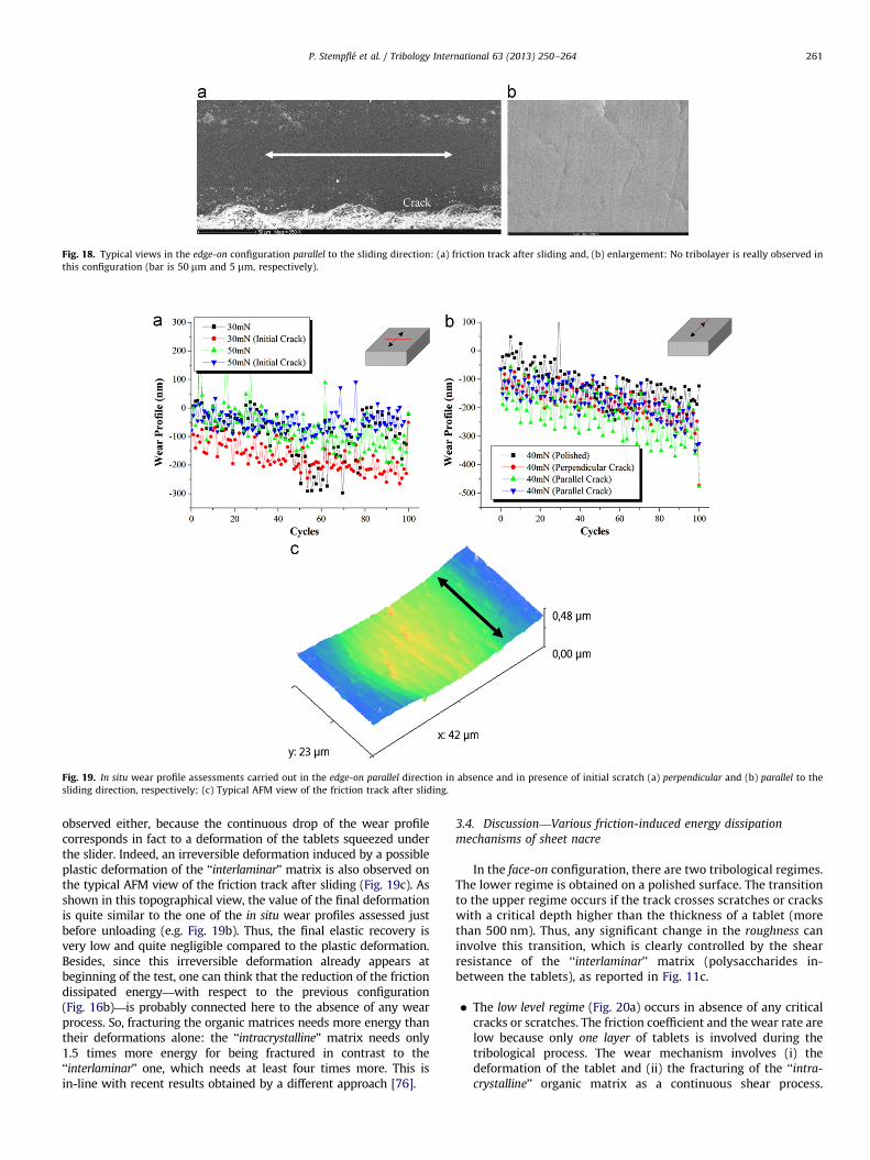
Fig. 18. Typical views in the edge-on configuration parallel to the sliding direction: (a) friction track after sliding and, (b) enlargement: No tribolayer is really observed in
this configuration (bar is 50 mm and 5 mm, respectively).
Fig. 19. In situ wear profile assessments carried out in the edge-on parallel direction in absence and in presence of initial scratch (a) perpendicular and (b) parallel to the
sliding direction, respectively; (c) Typical AFM view of the friction track after sliding.
P. Stempfle et al. / Tribology International 63 (2013) 250–264 261
observed either, because the continuous drop of the wear profilecorresponds in fact to a deformation of the tablets squeezed underthe slider. Indeed, an irreversible deformation induced by a possibleplastic deformation of the ‘‘interlaminar’’ matrix is also observed onthe typical AFM view of the friction track after sliding (Fig. 19c). Asshown in this topographical view, the value of the final deformationis quite similar to the one of the in situ wear profiles assessed justbefore unloading (e.g. Fig. 19b). Thus, the final elastic recovery isvery low and quite negligible compared to the plastic deformation.Besides, since this irreversible deformation already appears atbeginning of the test, one can think that the reduction of the frictiondissipated energy—with respect to the previous configuration(Fig. 16b)—is probably connected here to the absence of any wearprocess. So, fracturing the organic matrices needs more energy thantheir deformations alone: the ‘‘intracrystalline’’ matrix needs only1.5 times more energy for being fractured in contrast to the‘‘interlaminar’’ one, which needs at least four times more. This isin-line with recent results obtained by a different approach [76].
3.4. Discussion—Various friction-induced energy dissipation
mechanisms of sheet nacre
In the face-on configuration, there are two tribological regimes.The lower regime is obtained on a polished surface. The transitionto the upper regime occurs if the track crosses scratches or crackswith a critical depth higher than the thickness of a tablet (morethan 500 nm). Thus, any significant change in the roughness caninvolve this transition, which is clearly controlled by the shearresistance of the ‘‘interlaminar’’ matrix (polysaccharides in-between the tablets), as reported in Fig. 11c.
�
The low level regime (Fig. 20a) occurs in absence of any criticalcracks or scratches. The friction coefficient and the wear rate arelow because only one layer of tablets is involved during thetribological process. The wear mechanism involves (i) thedeformation of the tablet and (ii) the fracturing of the ‘‘intra-
crystalline’’ organic matrix as a continuous shear process.
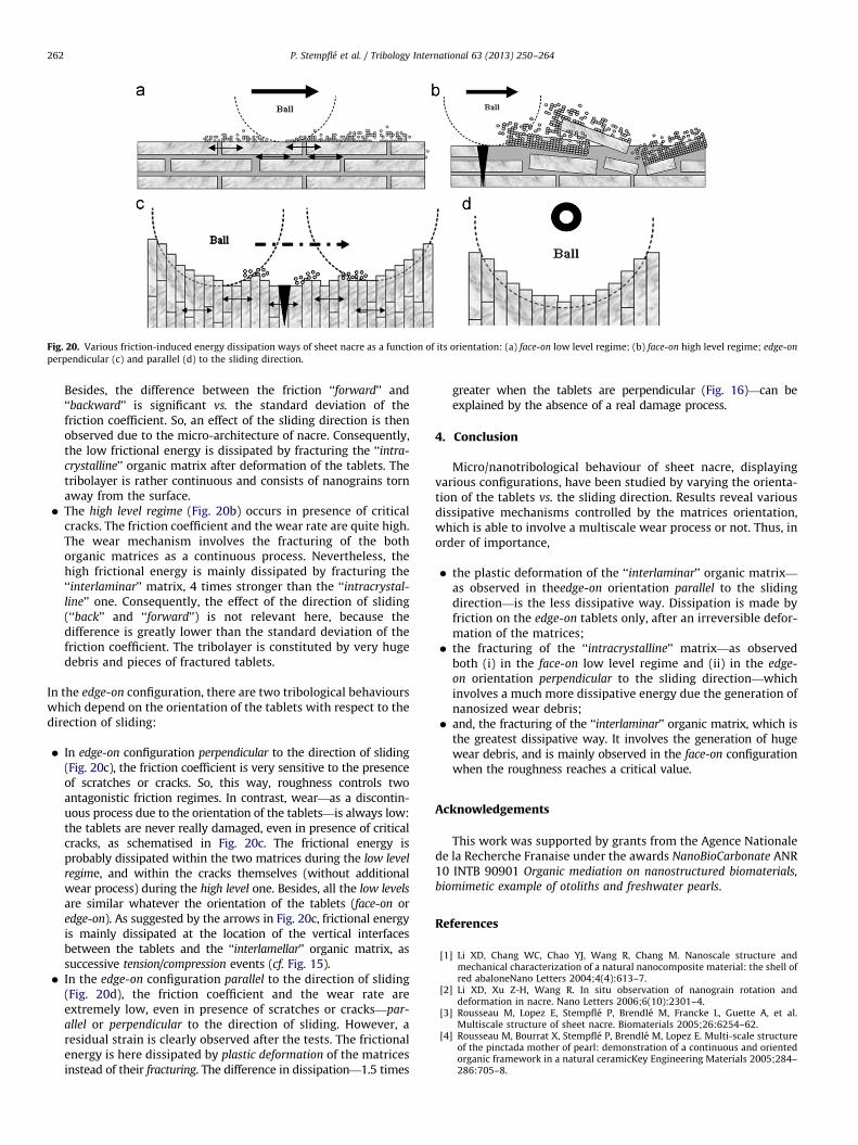
Fig. 20. Various friction-induced energy dissipation ways of sheet nacre as a function of its orientation: (a) face-on low level regime; (b) face-on high level regime; edge-on
perpendicular (c) and parallel (d) to the sliding direction.
P. Stempfle et al. / Tribology International 63 (2013) 250–264262
Besides, the difference between the friction ‘‘forward’’ and‘‘backward’’ is significant vs. the standard deviation of thefriction coefficient. So, an effect of the sliding direction is thenobserved due to the micro-architecture of nacre. Consequently,the low frictional energy is dissipated by fracturing the ‘‘intra-
crystalline’’ organic matrix after deformation of the tablets. Thetribolayer is rather continuous and consists of nanograins tornaway from the surface.
� The high level regime (Fig. 20b) occurs in presence of critical
cracks. The friction coefficient and the wear rate are quite high.The wear mechanism involves the fracturing of the bothorganic matrices as a continuous process. Nevertheless, thehigh frictional energy is mainly dissipated by fracturing the‘‘interlaminar’’ matrix, 4 times stronger than the ‘‘intracrystal-
line’’ one. Consequently, the effect of the direction of sliding(‘‘back’’ and ‘‘forward’’) is not relevant here, because thedifference is greatly lower than the standard deviation of thefriction coefficient. The tribolayer is constituted by very hugedebris and pieces of fractured tablets.
In the edge-on configuration, there are two tribological behaviourswhich depend on the orientation of the tablets with respect to thedirection of sliding:
�
In edge-on configuration perpendicular to the direction of sliding(Fig. 20c), the friction coefficient is very sensitive to the presenceof scratches or cracks. So, this way, roughness controls twoantagonistic friction regimes. In contrast, wear—as a discontin-uous process due to the orientation of the tablets—is always low:the tablets are never really damaged, even in presence of criticalcracks, as schematised in Fig. 20c. The frictional energy isprobably dissipated within the two matrices during the low level
regime, and within the cracks themselves (without additionalwear process) during the high level one. Besides, all the low levels
are similar whatever the orientation of the tablets (face-on oredge-on). As suggested by the arrows in Fig. 20c, frictional energyis mainly dissipated at the location of the vertical interfacesbetween the tablets and the ‘‘interlamellar’’ organic matrix, assuccessive tension/compression events (cf. Fig. 15).
� In the edge-on configuration parallel to the direction of sliding
(Fig. 20d), the friction coefficient and the wear rate areextremely low, even in presence of scratches or cracks—par-
allel or perpendicular to the direction of sliding. However, aresidual strain is clearly observed after the tests. The frictionalenergy is here dissipated by plastic deformation of the matricesinstead of their fracturing. The difference in dissipation—1.5 times
greater when the tablets are perpendicular (Fig. 16)—can beexplained by the absence of a real damage process.
4. Conclusion
Micro/nanotribological behaviour of sheet nacre, displayingvarious configurations, have been studied by varying the orienta-tion of the tablets vs. the sliding direction. Results reveal variousdissipative mechanisms controlled by the matrices orientation,which is able to involve a multiscale wear process or not. Thus, inorder of importance,
�
the plastic deformation of the ‘‘interlaminar’’ organic matrix—
as observed in theedge-on orientation parallel to the slidingdirection—is the less dissipative way. Dissipation is made byfriction on the edge-on tablets only, after an irreversible defor-mation of the matrices;
� the fracturing of the ‘‘intracrystalline’’ matrix—as observed
both (i) in the face-on low level regime and (ii) in the edge-
on orientation perpendicular to the sliding direction—whichinvolves a much more dissipative energy due the generation ofnanosized wear debris;
� and, the fracturing of the ‘‘interlaminar’’ organic matrix, which is
the greatest dissipative way. It involves the generation of hugewear debris, and is mainly observed in the face-on configurationwhen the roughness reaches a critical value.
Acknowledgements
This work was supported by grants from the Agence Nationalede la Recherche Franaise under the awards NanoBioCarbonate ANR10 INTB 90901 Organic mediation on nanostructured biomaterials,
biomimetic example of otoliths and freshwater pearls.
References
[1] Li XD, Chang WC, Chao YJ, Wang R, Chang M. Nanoscale structure andmechanical characterization of a natural nanocomposite material: the shell ofred abaloneNano Letters 2004;4(4):613–7.
[2] Li XD, Xu Z-H, Wang R. In situ observation of nanograin rotation anddeformation in nacre. Nano Letters 2006;6(10):2301–4.
[3] Rousseau M, Lopez E, Stempfle P, Brendle M, Francke L, Guette A, et al.Multiscale structure of sheet nacre. Biomaterials 2005;26:6254–62.
[4] Rousseau M, Bourrat X, Stempfle P, Brendle M, Lopez E. Multi-scale structureof the pinctada mother of pearl: demonstration of a continuous and orientedorganic framework in a natural ceramicKey Engineering Materials 2005;284–286:705–8.
P. Stempfle et al. / Tribology International 63 (2013) 250–264 263
[5] Weiner S, Traub W. Macromolecules in mollusc shells and their functions inbiomineralization. Philosophical Transactions of the Royal Society of London,Series B 1984;304:425–34.
[6] Bedouet L, Schuller M, Marin F, Milet C, Lopez E, Giraud M. Soluble proteins ofthe nacre of the giant oyster pinctada maxima and of the abalone haliotistuberculata: extraction and partial analysis of nacre proteinsComparativeBiochemistry and Physiology B 2001;128:389–400.
[7] Pereira-Mouri�es L, Almeida M-J, Ribeiro C, Peduzzi J, Barthelemy M, Milet C,et al. Soluble silk-like organic matrix in the nacreous layer of the bivalvepinctada maxima. European Journal of Biochemistry 2002;269:4994–5003.
[8] Rousseau M, Pereira-Mouri�es L, Almeida M-J, Milet C, Lopez E. The water-soluble matrix fraction from the nacre of pinctada maxima produces earliermineralization of mc3t3-e1 mouse pre-osteoblasts. Comparative Biochemistryand Physiology B 2003;135:1–7.
[9] Rousseau M, Meibom A, G�eze M, Bourrat X, Angellier M, Lopez E. Dynamics ofsheet nacre formation in bivalves. Journal of Structural Biology 2009;165:190–5.
[10] Levi-Kalisman Y, Falini G, Addadi L, Weiner S. Structure of the nacreousorganic matrix of a bivalve mollusk shell examined in the hydrated stateusing cryo-tem. Journal of Structural Biology 2001;135:8–17.
[11] Song F, Zhang X, Bai Y. Microstructure and characteristics in the organicmatrix layers of nacre. Journal of Materials Research 2002;17(7):1567–70.
[12] Falini G, Weiner S, Addadi L. Chitin-silk fibroin interactions: relevance tocalcium carbonate formation in invertebratesCalcified Tissue International2003;72:548–54.
[13] Song F, Soh A, Bai Y. Structural and mechanical properties of the organicmatrix layers of nacre. Biomaterials 2003;24:3623–31.
[14] Bourrat X, Qiao L, Feng Q, Angellier M, Disseaux A, Beny J-M, et al. Origin ofgrowth defects in pearl. Materials Characterization 2012;72:94–103.
[15] Currey J. Mechanical properties of mother-of-pearl in tension. Proceedings ofthe Royal Society of London, Series B 1977;196:443–63.
[16] Jackson A, Vincent J, Turner R. Comparison of nacre with other ceramiccomposites. Journals of Materials Science 1990;25:3173–8.
[17] Okumura K, de Gennes P-G. Why is nacre strong? Elastic theory and fracturemechanics for biocomposites with stratified structures European PhysicalJournal E 2001;4:121–7.
[18] Okumura K. Why is nacre strong? ii. remaining mechanical weakness forcracks propagating along sheets European Physical Journal E 2002;7:303–10.
[19] Ji B, Gao H. Mechanical properties of nanostructure of biological materials.Journal of the Mechanics and Physics of Solids 2004;52:1963–90.
[20] Meyers M, Chen P-Y, Lin A-M, Seki Y. Biological materials: structure andmechanical propertiesProgress in Materials Science 2008;53:1–206.
[21] Bruet BJF, Qi HJ, Boyce MC, Panas R, Tai K, Frick L, Ortiz C. Nanoscalemorphology and indentation of individual nacre tablets from the gastropodmollusc trochus niloticus. Journal of Materials Research 2005;20(9):2400–19.
[22] Westbroek P, Marin F. A marriage of bone and nacre. Nature 1998;392:861–2.
[23] Atlan G, Delattre O, Berland S, LeFaou A, Nabias G, Cot D, et al. Interfacebetween bone and nacre implants in sheep. Biomaterials 1999;20:1017–22.
[24] Kim Y, Kim J, Kim Y, Rho J-Y. Effect of organic matrix proteins on theinterfacial structure at the bone biocompatible nacre interface in vivo.Biomaterials 2002;23:2089–96.
[25] Liao H, Mutvei H, Hammarstrom L, Wurtz T, Li J. Tissue responses to nacreousimplants in rat femur: an in situ hybridation and histochemical study-Biomaterials 2002;23:2693–701.
[26] Lopez E, Berland S, Camprasse C, Camprasse G, Silve C. Demonstration of thecapacity of nacre to induce bone formation by human osteoblasts maintainedin vitro. Tissue Cell 1992;24:667–79.
[27] Berland S, Delattre O, Borzeix S, Catonne Y, Lopez E. Nacre/bone interfacechanges in durable nacre endosseous implants in sheep. Biomaterials2005;26:2767–73.
[28] Silve C, Lopez E, Vidal B, Smith D, Camprasse G, Camprasse C, et al. Nacreinitiates biomineralization by human osteoblasts maintained in vitro. Calci-fied Tissue International 1992;51(5):363–9.
[29] Heuer A, Fink D, Laraia V, Arias J, Calvert P, Kendall K. Innovative materialsprocessing strategies: a biomimetic approachScience 1992;255:1098–105.
[30] Weiner S, Addadi L. Design strategies in mineralized biological materials.Journal of Materials Chemistry 1997;7(5):689–702.
[31] Wang C, Huang Y, Zan Q, Guo H, Cai S. Biomimetic structure design – apossible approach to change the brittleness of ceramics in nature. MaterialsScience and Engineering C 2000;11:9–11.
[32] Carlson J, Ghaey S, Moran S, Tran C, Kaplan D. Biological materials inengineering mechanisms. In: Bar-Cohen YE, editor. Biomimetics, biologicallyinspired technologies. Boca Raton, FL: CRC Taylor & Francis; 2006. p. 365–79.
[33] Fratzl P. Biomimetic materials research: what can we really learn fromnature’s structural materials?Journal of the Royal Society Interface2007;4:637–42.
[34] Munch E, Launey M, Alsem D, Saiz E, Tomsia A, Ritchie R. Tough, bio-inspiredhybrid materials. Science 2008;322:516–20.
[35] Bhushan B. Biomimetics: lessons from nature – an overviewPhilosophicalTransactions of the Royal Society, Series A 2009;367:1445–86.
[36] Stempfle P, Brendle M. Tribological behaviour of nacre – influence of theenvironment on the elementary wear processes. Tribology International2006;39:1485–96.
[37] Stempfle P, Pantale O, Kouitat Njiwa R, Rousseau M, Lopez E, Bourrat X.Friction-induced sheet nacre fracture: effects of nano-shocks on crackslocationInternational Journal of Nanotechnology 2007;4(6):712–29.
[38] Stempfle P, Djilali T, Kouitat Njiwa R, Rousseau M, Lopez E, Bourrat X.Thermal-induced wear mechanisms of sheet nacre in dry friction. TribologyLetters 2009;35:97–104.
[39] Stempfle P, Pantale O, Djilali T, Kouitat Njiwa R, Bourrat X. Evaluation of thereal contact area in three-body dry friction by micro-thermal analysis.Tribology International 2010;43:1794–805.
[40] Stempfle P, Djilali T, Kouitat Njiwa R, Rousseau M, Lopez E, Bourrat X.Assessment of the thermal-induced wear mechanisms of sheet nacre byusing scanning thermal microscopy. In: Proceedings of the 3rd internationalconference nanotechnology – Viennano’09, March 18–20, 2009; Vienna,Austria; 2009. p. 409–14.
[41] Bourrat X, Francke L, Lopez E, Rousseau M, Stempfle P, Angellier M, et al.Nacre biocrystal thermal behaviour. CrystEngCommunity 2007;9:1205–8.
[42] Wang R, Wen H, Cui F, Zhang H, Li H. Observations of damage morphologiesin nacre during deformation and fracture. Journal of Materials Science1995;30:2299–304.
[43] Evans A, Suo Z, Wang R, Aksay I, He M, Hutchinson J. Model for the robustmechanical behaviour of nacre. Journal of Materials Research 2001;16(9):2475–84.
[44] Wang R, Suo Z, Evans A, Yao N, Aksay I. Deformation mechanisms in nacre.Journal of Materials Research 2001;16(9):2485–93.
[45] Okumura K. Fracture strength of biomimetic composites: scaling views ofnacreJournal of PhysicsCondensed Matter. 2005;17:S2879–84.
[46] Sumitomo T, Kakisawa H, Owaki Y, Kagawa Y. Transmission electron micro-scopy observation of nanoscale deformation structures in nacre. Journal ofMaterials Research 2008;23(12):3213–21.
[47] Meyers M, Lin A-M, Chen P-Y, Muyco J. Mechanical strength of abalone nacre:role of the soft organic layerJournal of the Mechanical Behavior of BiomedicalMaterials 2008;1:76–85.
[48] Jackson A, Vincent J, Briggs D, Crick R, Davies S, Hearn M, et al. Application ofsurface analytical techniques to the study of fracture surfaces of mother-of-pearl. Journal of Materials Science Letters 1986;5:975–8.
[49] Kotha S, Li Y, Guzelsu N. Micromechanical model of nacre tested in tension.Journal of Materials Science 2001;36:2001–7.
[50] Neves N, Mano J. Structure/mechanical behavior relationships in crossed-lamellar sea shells. Materials Science and Engineering C 2005;25:113–8.
[51] Nukala P, Simunovic S. A continuous damage random thresholds model forsimulating the fracture behavior of nacre. Biomaterials 2005;26:6087–98.
[52] Cortie M, McBean K, Elcombe M. Fracture mechanics of mollusc shells.Physica B 2006;385–386:545–7.
[53] Barthelat F, Tang H, Zavattieri P, Li C-M, Espinosa H. On the mechanics ofmother-of-pearl: a key feature in the material hierarchical structureJournalof the Mechanics and Physics of Solids 2007;55:306–37.
[54] Okumura K. Enhanced energy of parallel fractures in nacre-like compositematerials. Europhysics Letters 2003;63(5):701–7.
[55] Vincent J. Structural biomaterials. revised editionPrinceton University Press;1990.
[56] Qi H, Bruet B, Palmer J, Ortiz C, Boyce M. Micromechanics and macromecha-nics of the tensile deformation of nacre. In: Holzapfel G, Ogden R, editors.Mechanics of Biological Tissue. Berlin Heidelberg: Springer Verlag; 2006.p. 189.
[57] Menig R, Meyers M, Meyers M, Vecchio K. Quasi-static and dynamicmechanical response of Haliotis rufescens (abalone) shells. Acta Materialia2000;48:2383–98.
[58] Laraia V, Heuer A. The microindentation behavior of several mollusk shells.Materials Research Society Symposium Proceedings 1990;174:125–31.
[59] Ge L, Kim N, Bourne GR, Sawyer WG. Material property identification andsensitivity analysis using micro-indentation. Journal of Tribology 2009;131031402–17.
[60] Stempfle P, Pantale O, Kouitat Njiwa R, Rousseau M, Lopez E, Bourrat X.Nanoindentation & tribological tests – suitable tools for modelling thenanostructure of sheet nacre. In: Bartz W, Franek F, editors. Proceedings ofthe 2nd international conference micro-nanotechnology – Viennano’07March 2007; Vienna, Austria, 2007, p. 153–9.
[61] Mohanty B, Katti K, Katti D. Experimental investigation of nanomechanics ofthe mineral-protein interface in nacre. Mechanics Research Communications2008;35:17–23.
[62] Stempfle P, Pantale O, Rousseau M, Lopez E, Bourrat X. Mechanical propertiesof the elemental nanocomponents of nacre structure. Materials Science andEngineering C 2010;30:715–21.
[63] P. Stempfle, X. Bourrat, R. Kouitat, M. Rousseau, E. Lopez, Mechanicalproperties of sheet nacre porous intercrystalline organic matrix, in preparation.
[64] Scherge M, Gorb S. Microtribology of biological materials. Tribology Letters2000;8:1–7.
[65] Scherge M, Gorb S. Biological micro-nano-tribology. Berlin, Heidelberg, NewYork: Springer Verlag; 2001.
[66] Stempfle P, Takadoum J. Multi-asperity nanotribological behavior of single-crystal silicon: crystallography-induced anisotropy in friction and wearTribology International 2012;48:35–43.
[67] Sud D, Doumenc D, Lopez E, Milet C. Role of water-soluble matrix fraction,extracted from the nacre of pinctada maxima, in the regulation of cell activityin abalone mantle cell culture (haliotis tuberculata). Tissue Cell 2001;33(2):154–60.
[68] Addadi L, Weiner S. A pavement of pearl. Nature 1997;389:912–3.[69] Huang L, Li H. The microstructure of the biomineralization bivalvia shells.
Materials Research Society Symposium Proceedings 1990;174:101–8.
P. Stempfle et al. / Tribology International 63 (2013) 250–264264
[70] Maev R. Acoustic microscopy: fundamentals and applicationsWiley-VCHVerlag; 2008.
[71] Xu Z-H, Yang Y, Huang Z, Li X. Elastic modulus of biopolymer matrix in nacremeasured using coupled atomic force microscopy bending and inverse finiteelement techniques. Materials Science and Engineering C 2011;31:1852–6.
[72] Stempfle P, Takadoum J, Kouitat Njiwa R, An accurate in-situ wear assess-ment in micro/nanotribology. In: Bartz W, Franek F, editors. Proceedings of the3rd European Conference on Tribology, June 7–9, 2011; Vienna, Austria; 2011.
[73] Hill I, Sawyer WG. Energy, adhesion, and the elastic foundation. TribologyLetters 2010;37:453–61.
[74] Stempfle P, Pollet F, Carpentier L. Influence of intergranualr metallic nano-particles on the fretting wear mechanisms of Fe–Cr–Al2O3 nanocompositesrubbing on Ti–6Al–4V. Tribology International 2008;41:1009–19.
[75] Stempfle P, von Stebut J. Nano-mechanical behaviour of the 3rd bodygenerated in dry friction – feedback effect of the 3rd body and influence ofthe surrounding environment on the tribology of graphite. Wear 2006;260:601–14.
[76] Bezares J, Asaro R, Hawley M. Macromolecular structure of the organicframework of nacre in haliotis rufescens: implications for mechanicalresponseJournal of Structural Biology 2010;170:484–500.