Liquid crystal (LC) clad-glass core highly multimode waveguides, with a column array of interdigitated electrodes arranged on the LC layer remote from the core-cladding interface, have been electrically switched between guiding and nonguiding states. The time for 63 % recovery is 135-250 μs, and 90% recovery is ~0.8 ms.
Most optical devices employing liquid crystals (LCs) are transmissive structures in which the LC is sandwiched between polarized transparent plates. The LC is switched electrically, having a driven ON-time (tON) constant which is
field dependent and a nondriven OFF-time constant (OFF) which is property dependent. Due to the relatively large viscosity of the LC director and the cell thickness dependence, the electrooptic (EO) response of such optical systems can be in tens to hundreds of milliseconds. Various groups have studied electrically switched waveguide structures with glass core and nematic LC cladding. Of these two groups, two have noted that there is an enhancement in the recovery (compared with the expected bulk response time). Thus Soref1 and Okamura et al.2 report a recovery time of ~4 ms, while Channin3 reports a time of 3 ms to 50% recovery without distinguishing surface from bulk effects. We have been studying4 waveguide structures consisting of glass core and LC cladding using an interdigitated electrode (IDE) structure to modulate the LC. In this case, it is the behavior in the evanescent region which is of prime importance, and in this region, under the influence of surface interactions, we find a much larger reduction in the recovery time tOFF than the expected bulk response. We have now carried out two completely independent sets of experiments on two LC mixtures and obtain essentially submillisecond recovery times,
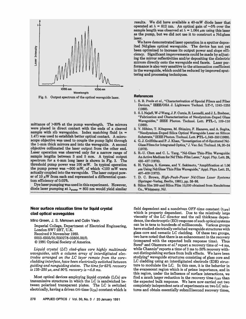
Fig. 1. Side view arrangement of the glass core-LC waveguide structure with local switching of the LC directors (not to scale, see text for dimensions).
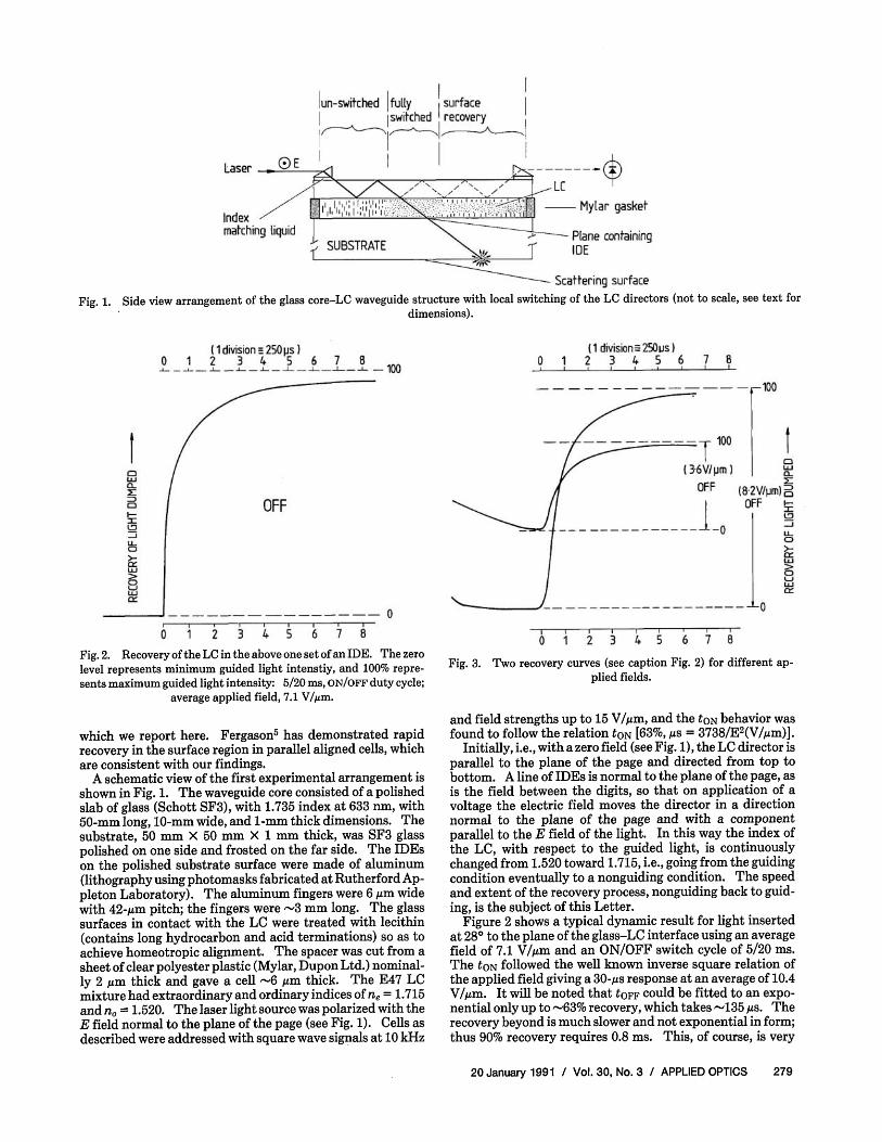
Fig. 2. Recovery of the LC in the above one set of an IDE. The zero level represents minimum guided light intenstiy, and 100% represents maximum guided light intensity: 5/20 ms, ON/OFF duty cycle;
average applied field, 7.1 V/μm.
which we report here. Fergason5 has demonstrated rapid recovery in the surface region in parallel aligned cells, which are consistent with our findings.
A schematic view of the first experimental arrangement is shown in Fig. 1. The waveguide core consisted of a polished slab of glass (Schott SF3), with 1.735 index at 633 nm, with 50-mm long, 10-mm wide, and 1-mm thick dimensions. The substrate, 50 mm × 50 mm × 1 mm thick, was SF3 glass polished on one side and frosted on the far side. The IDEs on the polished substrate surface were made of aluminum (lithography using photomasks fabricated at Rutherford Ap-pleton Laboratory). The aluminum fingers were 6 μm wide with 42-μm pitch; the fingers were ~3 mm long. The glass surfaces in contact with the LC were treated with lecithin (contains long hydrocarbon and acid terminations) so as to achieve homeotropic alignment. The spacer was cut from a sheet of clear polyester plastic (Mylar, Dupon Ltd.) nominally 2 μm thick and gave a cell ~6 μm thick. The E47 LC mixture had extraordinary and ordinary indices of ne = 1.715 and n0 = 1.520. The laser light source was polarized with the E field normal to the plane of the page (see Fig. 1). Cells as described were addressed with square wave signals at 10 kHz
Fig. 3. Two recovery curves (see caption Fig. 2) for different applied fields.
and field strengths up to 15 V/μm, and the toN behavior was found to follow the relation t0N [63%, μs = 3738/E2(V/μm)j.
Initially, i.e., with a zero field (see Fig. 1), the LC director is parallel to the plane of the page and directed from top to bottom. A line of IDEs is normal to the plane of the page, as is the field between the digits, so that on application of a voltage the electric field moves the director in a direction normal to the plane of the page and with a component parallel to the E field of the light. In this way the index of the LC, with respect to the guided light, is continuously changed from 1.520 toward 1.715, i.e., going from the guiding condition eventually to a nonguiding condition. The speed and extent of the recovery process, nonguiding back to guiding, is the subject of this Letter.
Figure 2 shows a typical dynamic result for light inserted at 28° to the plane of the glass-LC interface using an average field of 7.1 V/μm and an ON/OFF switch cycle of 5/20 ms. The toN followed the well known inverse square relation of the applied field giving a 30-μs response at an average of 10.4 V/μm. It will be noted that tOFF could be fitted to an exponential only up to ~63% recovery, which takes ~135 μs. The recovery beyond is much slower and not exponential in form; thus 90% recovery requires 0.8 ms. This, of course, is very
Fig. 4. Spatial variation of the angle between the director and the normal to glass surface as viewed end on to the waveguide (not to scale). The thickness of the recovered region is comparable with the
evanescent field depths of importance (of the order of 1 μm).
much faster than the 500-ms measured bulk recovry time of a 5-μm thick cell.
The second experimental arrangement was similar to the first, differing from it in the following ways: the LC was E206 (BDH Ltd.) with ne = 1.680 and n0 = 1.508 at 589 nm, and the glass of the core and electrode substrate was Schott BaF50 with 1.683 index at 587 nm. The waveguide was 50 mm long by 1.2 mm wide by 0.45 mm thick. The Mylar spacer was 12 μm thick. The light was a yellow LED whose plastic capsule had been polished away to <0.5 mm of the emitting surface; this source was butted up to the end of the glass core.
Figure 3 shows recovery curves for two different switching fields yielding 63% recovery of 215 μs for 8.2 and 3.6 V/μm. Once again the more extensive recovery, e.g., 90%, requires longer times than that predicted by an exponential, namely, 0.8 ms. It should be noted that the data for this experiment refer to a range of angles essentially within the critical value and, therefore, probe the LC to relatively large evanescent field depths. Faster recovery time is expected for lower angle modes.
The interpretation of these data is most easily done using the director diagrams shown in Fig. 4. In (a) we have the initial condition with the director normal to the surface. In (b) the LC has been fully switched by a high field (e.g., 10 V/ μm) so that the director is parallel to the glass core throughout most of the volume and especially within a short distance of the glass surface. In (c) the field has been turned off a short time before. Here the LC in the vicinity of the glass-LC interface has recovered to the initial condition (a). However, the more usual ON/OFF duty recovery is attributed to the glass-LC interaction. A quantitative study of the director shape, transmission properties of such a layer, and response behavior is being carried out.
The essential point of this Letter is to report the significantly decreased response time of LC in a layer comparable in thickness to the evanescent light field and to note that this will have a highly beneficial effect on the characteristics of EO waveguide devices using a LC.
Technel, Ltd. has suported J.S.M. and Dupont (U.K.) has given C.Y. a full bursary. We are deeply grateful to both companies, and it is a pleasure to record our thanks.
References 1. R. A. Soref, "Electrooptic 4 × 4 Matrix for Multimode Fiber-
Optic Systems," Appl. Opt. 21, 1386-1393 (1982). 2. Y. Okamura, K. Kitatani, and S. Yamamoto, "Electrooptic Leaky
Anisotropic Waveguides Using Nematic Liquid Crystal Over-layers," IEEE/OSA J. Lightwave Technol. LT-2, 292-295 (1984).
3. D. J. Channin, "Optical Waveguide Modulation Using Nematic Liquid Crystal," Appl. Phys. Lett. 22, 365-366 (1973).
4. M. Green and J. S. Menown, "Flat Liquid Crystal Waveguide Display," Proc. Soc. Inf. Disp. 26, 163-165 (1985).
5. J. L. Fergason, "Use of Strong Surface Alignment in Nematic Liquid Crystals for High Speed Light Modulation," Proc. Soc. Photo-Opt Instrum. Eng. 684, 81-86 (1986).