MAE 6530, Propulsion Systems II Section 3 Rocket Science Review 103: Estimating the Launch Vehicle Drag Coefficient Newton's Laws as Applied to "Rocket Science" ... its not just a job ... its an adventure 1
Transcript
MAE 6530, Propulsion Systems II
Section 3Rocket Science Review 103:
Estimating the Launch Vehicle Drag Coefficient
Newton's Laws asApplied to
"Rocket Science"... its not just a job ... its an
adventure
1
MAE 6530, Propulsion Systems II
RS 101: SummaryExternal Forces Acting on Rocket
2
•Lift – acts perpendicular to flight path (non-conservative)•Drag – acts along flight path (non-conservative)•Thrust – acts along longitudinal axis of rocket (non-conservative)•Gravity – acts downward (conservative)
Drag Mechanisms Acting on Launch Vehicles (LVs)• Subsonic
o Viscous drag–Wetted Area Skin Friction–Flow Separation (small for LVs)
o Pressure drag (form drag)– Forebody– Interference (fin roots)– Base
o Induced (lift drag, small for LVs)• Supersonic
o Wave drago Compressive drag due to lift
• “Dither” Drag due to unsteady a modulation• Total drag
MAE 6530, Propulsion Systems II
5
Skin Friction Drag
dAτwall
Flow Momentum lost due to surface viscosity
CF =τwall ⋅dA
surf∫∫q ⋅ Awet
Awet
CDF=
Awet
Aref
⋅CF →
CF = skin friction coefficient
Awet = forebody wetted surface area
Aref = vehicle reference area, π4⋅Dmax
2
MAE 6530, Propulsion Systems II6
2-D Skin Friction Drag
Bypass transition
Blasius Law
CF =7
225⋅ ReL( )1/7
MAE 6530, Propulsion Systems II7
Axisymmetric 3-D Skin Friction Drag
MAE 6530, Propulsion Systems II8
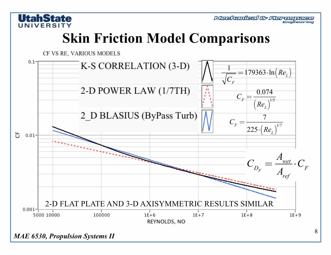
Skin Friction Model Comparisons
1CF=179363⋅ ln ReL( )
CF =0.074
ReL( )1/5
CF =7
225⋅ ReL( )1/7
2-D FLAT PLATE AND 3-D AXISYMMETRIC RESULTS SIMILAR
CDF =AwetAref⋅CF
MAE 6530, Propulsion Systems II
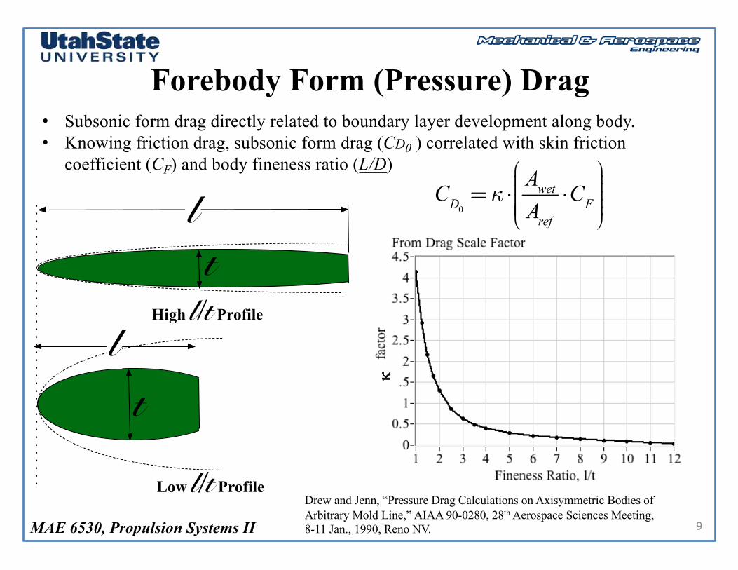
Forebody Form (Pressure) Drag
9
• Subsonic form drag directly related to boundary layer development along body. • Knowing friction drag, subsonic form drag (CD0 ) correlated with skin friction
coefficient (CF) and body fineness ratio (L/D)
CD0 =κ ⋅AwetAref⋅CF
⎛
⎝
⎜⎜⎜⎜⎜
⎞
⎠
⎟⎟⎟⎟⎟
High l/t Profile
lt
Low l/t Profile
lt
k
Drew and Jenn, “Pressure Drag Calculations on Axisymmetric Bodies of Arbitrary Mold Line,” AIAA 90-0280, 28th Aerospace Sciences Meeting, 8-11 Jan., 1990, Reno NV.
MAE 6530, Propulsion Systems II 10
• Boundary Layer on Vehicle Base Area Separates
• Low Pressure Separated Region Forms• Low Pressure Causes a Large net Pressure
Difference• Especially significant on Launch Vehicle
after motor burnout
Base Drag
MAE 6530, Propulsion Systems II
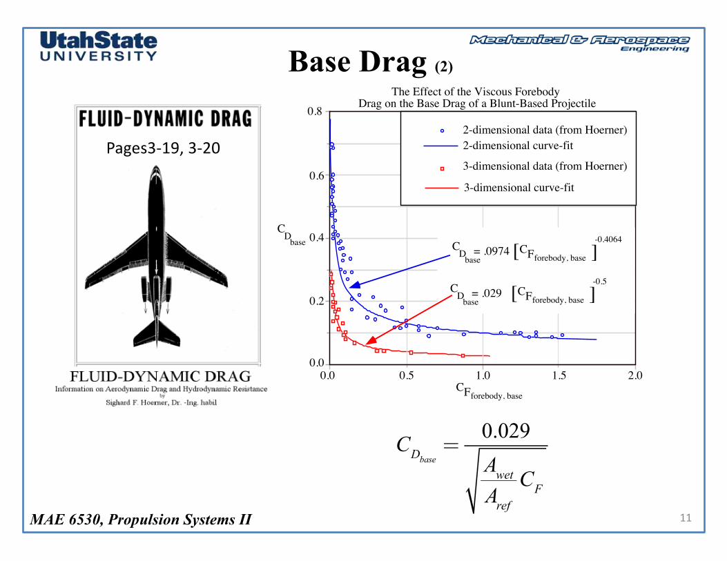
Base Drag (2)
11
0.8
0.6
0.4
0.2
0.00.0 0.5 1.0 1.5 2.0
CD
base
CFforebody, base
2-dimensional curve-fit
3-dimensional curve-fit
2-dimensional data (from Hoerner)
3-dimensional data (from Hoerner)
CD
base= .0974 CFforebody, base[ [
-0.4064
CD
base= .029 CFforebody, base[ [
-0.5
The Effect of the Viscous Forebody Drag on the Base Drag of a Blunt-Based Projectile
Pages3-19,3-20
CDbase =0.029AwetAref
CF
MAE 6530, Propulsion Systems II
Base Drag (3)
12
Base Drag
Base Drag
Burning Rocket Pressurizes Base Area, Eliminating Base Drag
MAE 6530, Propulsion Systems II
Base Drag (4)
13
• Effect of “Boat Tailing” – Boat tail used on the rear end of rocket to reduce the base drag force by reducing area against which aft end pressure suction acts
• Effect of “Boat Tailing” – Boat tail Also serves to reduce the severity of the flow separation by reducing the exit turning angle
CDboattail≈CDbase ⋅
dD
⎛
⎝⎜⎜⎜⎞
⎠⎟⎟⎟⎟
2
MAE 6530, Propulsion Systems II
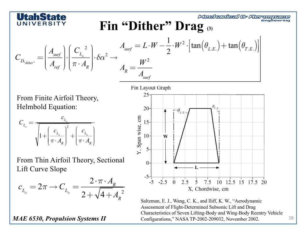
Fin “Dither” Drag
14
• Even along Ballistic Trajectory where nominal a ~ 0, fins can contribute induced drag to configuration due to unsteady “dither” or fin misalignment
• Shed Vortex from base is Unsteady and Contributes to Pitch Oscillations to Vehicle
•”Dither” Drag due to Small angle of attack oscillations results in RMS drag contribution
20 ft.
7.5 ft.
5 ft.
9.5 ft.
M2-F1
"Vortex Street"
Figure 4: Von Karman "Vortex Street" Formation Trailing M2-F1 Aircraft
“Vortex Street” trailing M2-F1
δα>0
δα= 0
δα<0
MAE 6530, Propulsion Systems II
Fin “Dither” Drag (2)
15
δα>0
δα= 0
δα<0
Dither” = Unsteady Induced Drag Component
Asurf = Planform area
CLα= Lift−curve slope
AR = Aspect ratio
δαdither = RMS angle of attack dither
CD "dither"=AsurfAref
⎛
⎝
⎜⎜⎜⎜⎜
⎞
⎠
⎟⎟⎟⎟⎟⋅CL
2
π ⋅ AR
⎛
⎝⎜⎜⎜⎜
⎞
⎠⎟⎟⎟⎟⎟=
AsurfAref
⎛
⎝
⎜⎜⎜⎜⎜
⎞
⎠
⎟⎟⎟⎟⎟⋅CLα
2
π ⋅ AR
⎛
⎝
⎜⎜⎜⎜⎜
⎞
⎠
⎟⎟⎟⎟⎟⎟⋅δαdither
2
MAE 6530, Propulsion Systems II
Fin “Dither” Drag (3)
16
From Finite Airfoil Theory,Helmbold Equation:
From Thin Airfoil Theory, Sectional Lift Curve Slope
CLα =cLα
1+cLαπ ⋅ AR
⎛
⎝
⎜⎜⎜⎜⎜
⎞
⎠
⎟⎟⎟⎟⎟
2
+cLαπ ⋅ AR
⎛
⎝
⎜⎜⎜⎜⎜
⎞
⎠
⎟⎟⎟⎟⎟
cLα = 2π→CLα =2 ⋅π ⋅ AR
2+ 4+AR2
CD"dither" =AsurfAref
⎛
⎝
⎜⎜⎜⎜⎜
⎞
⎠
⎟⎟⎟⎟⎟⋅CLα
2
π ⋅ AR
⎛
⎝
⎜⎜⎜⎜⎜
⎞
⎠
⎟⎟⎟⎟⎟⎟⋅δα2→
Asurf = L ⋅W −12⋅W 2 ⋅ tan θL.E .( )+ tan θT .E .( )⎡
⎣⎢⎤⎦⎥
AR =W 2
Asurf
Saltzman, E. J., Wang, C. K., and Iliff, K. W., “Aerodynamic Assessment of Flight-Determined Subsonic Lift and Drag Characteristics of Seven Lifting-Body and Wing-Body Reentry Vehicle Configurations,” NASA TP-2002-209032, November 2002.
MAE 6530, Propulsion Systems II
Fin “Dither” Drag (4)
17
Asurf = L ⋅W −12⋅W 2 ⋅ tan θL.E .( )+ tan θT .E .( )⎡
⎣⎢⎤⎦⎥
AR =W 2
Asurf
CD"dither"( )totalfins
=AsurfiAref
⎛
⎝
⎜⎜⎜⎜⎜
⎞
⎠
⎟⎟⎟⎟⎟i=1
N fins
∑ ⋅
2 ⋅π ⋅ ARi2+ 4+ARi
2
⎛
⎝
⎜⎜⎜⎜⎜⎜
⎞
⎠
⎟⎟⎟⎟⎟⎟⎟
2
π ⋅ ARi⋅δα2 =
AsurfiAref
⎛
⎝
⎜⎜⎜⎜⎜
⎞
⎠
⎟⎟⎟⎟⎟⋅
4 ⋅π ⋅ ARi2+ 4+ARi
2( )2
⎛
⎝
⎜⎜⎜⎜⎜⎜⎜⎜
⎞
⎠
⎟⎟⎟⎟⎟⎟⎟⎟⎟
⎧
⎨
⎪⎪⎪⎪
⎩⎪⎪⎪⎪
⎫
⎬
⎪⎪⎪⎪
⎭⎪⎪⎪⎪
i=1
N fins
∑ ⋅δα2
MAE 6530, Propulsion Systems II
Fin Leading Edge Drag
18
• Stagnation Pressure Coefficient calculated based on Mach number Normal to leading edge of fins
• Scaled by leading edge area, W•t• Assumed fin thickness, t
Cpmax =qc− p∞q
=p∞ ⋅ 1+
γ−12M⊥
2⎛
⎝⎜⎜⎜
⎞
⎠⎟⎟⎟⎟
γγ−1− p∞
γ2p∞M⊥
2=1+ γ−1
2⋅ M∞ ⋅cosθL.E .( )2
⎛
⎝⎜⎜⎜
⎞
⎠⎟⎟⎟⎟
γγ−1−1
γ2⋅ M∞ ⋅cosθL.E .( )2
CDL .E .( )totalfins
=Wi ⋅tiAref
⎛
⎝
⎜⎜⎜⎜⎜
⎞
⎠
⎟⎟⎟⎟⎟i=1
N fins
∑ ⋅ CPmax( )subsonic{ }
i=
Wi ⋅tiAref
⎛
⎝
⎜⎜⎜⎜⎜
⎞
⎠
⎟⎟⎟⎟⎟i=1
N fins
∑ ⋅1+ γ−1
2⋅ M∞ ⋅cosθL.E .( )
i
2⎛
⎝⎜⎜⎜
⎞
⎠⎟⎟⎟⎟
γγ−1−1
γ2⋅ M∞ ⋅cosθL.E .( )
i
2
⎧
⎨
⎪⎪⎪⎪⎪⎪⎪
⎩
⎪⎪⎪⎪⎪⎪⎪
⎫
⎬
⎪⎪⎪⎪⎪⎪⎪
⎭
⎪⎪⎪⎪⎪⎪⎪i
MAE 6530, Propulsion Systems II
Total Drag Correlation Model
19
CD( )total=CDF +CD0 +CDbase +CDDither +CDL .E .
Skin FrictionDrag
Nose/BodyProfile Pressure
Drag
Base AreaWake Drag
Unsteady DitherDrag, Fins Fins, Leading
Edge Pressure Drag
• Medium Fidelity Engineering Model for “First Cut” Drag Coefficient Estimator.
• Rigorously, each term of the above equation should be scaled for compressibility at Higher Mach numbers
• Operationally, Bulk scaling of is often used CD( )total
• Does not Model Wave Drag
MAE 6530, Propulsion Systems II
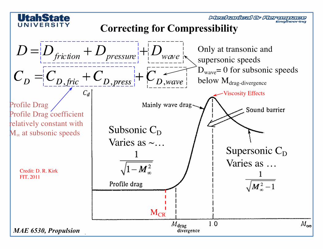
Correcting for Compressibility
20
wdpdfdd
wavepressurefriction
ccccDDDD
,,, ++=
++= Only at transonic andsupersonic speedsDwave= 0 for subsonic speedsbelow Mdrag-divergence
Profile DragProfile Drag coefficient relatively constant with M∞ at subsonic speeds
Credit: D. R. KirkFIT, 2011
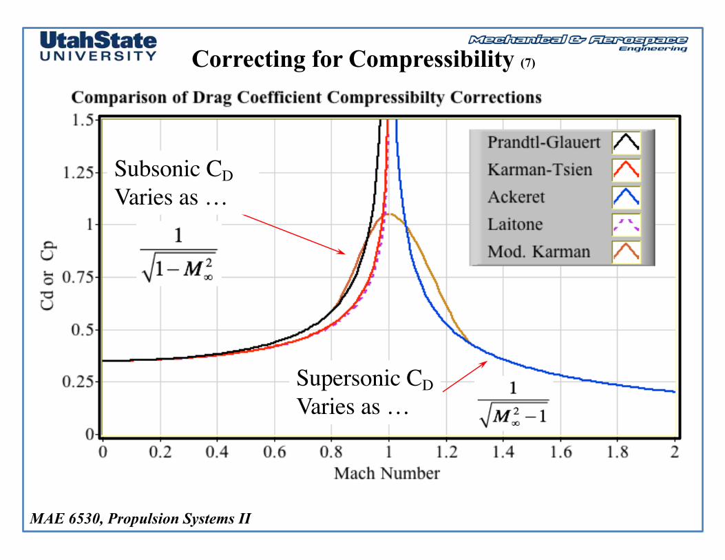
Supersonic CDVaries as …
Subsonic CDVaries as ~…
MCR
Viscosity Effects
MAE 6530, Propulsion Systems II
Correcting for Compressibility (2)
• Several Simple Transformations exist that allows us to take compressible transonic flow and map back to an “equivalent” incompressible body
• Equivalently, compressibility corrections allow the pressure coefficient of an incompressible airfoil to be transformed into compressible flow on the same body. Since inviscid lift and drag are related directly to the pressure coefficient, similar corrections hold.
• Transformations are written as a function of Freestream Mach number.
CL ,CD ,Cp{ }M∞≡ CL ,CD ,Cp{ }
M=0⋅ f M
∞( )
MAE 6530, Propulsion Systems II
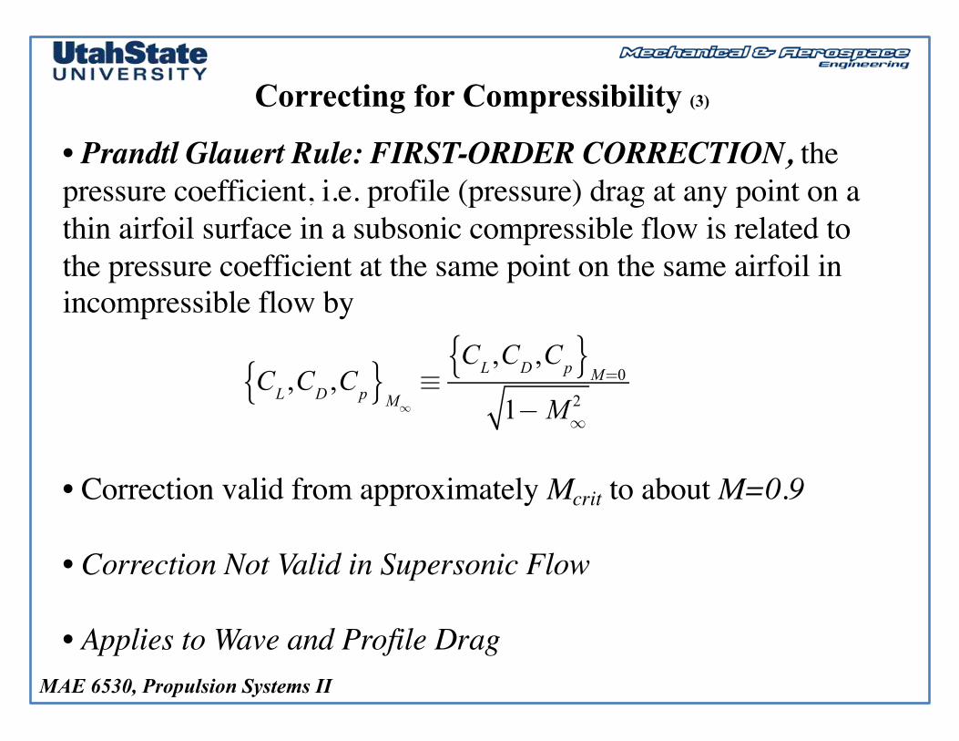
Correcting for Compressibility (3)
• Prandtl Glauert Rule: FIRST-ORDER CORRECTION, the pressure coefficient, i.e. profile (pressure) drag at any point on a thin airfoil surface in a subsonic compressible flow is related to the pressure coefficient at the same point on the same airfoil in incompressible flow by
• Correction valid from approximately Mcrit to about M=0.9
• Correction Not Valid in Supersonic Flow
• Applies to Wave and Profile Drag
CL ,CD ,Cp{ }M∞≡CL ,CD ,Cp{ }
M=0
1−M∞2
MAE 6530, Propulsion Systems II
Correcting for Compressibility (4)
• Karman-Tsien Rule: FIRST-ORDER CORRECTION, the pressure coefficient, i.e. profile (pressure) drag at any point on a thin airfoil surface in a subsonic compressible flow is related to the pressure coefficient at the same point on the same airfoil in incompressible flow by
• Correction valid from approximately Mcrit to about M=0.98
• Correction Not Valid in Supersonic Flow
• Applies to Wave and Profile Drag
CL ,CD ,Cp{ }M∞≡
CL ,CD ,Cp{ }M=0
1−M∞2 +
M∞2
1+ 1−M∞2⋅CL ,CD ,Cp{ }
M=0
2
MAE 6530, Propulsion Systems II
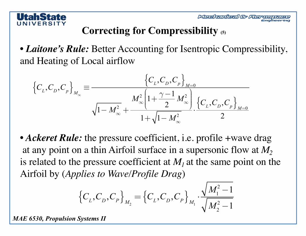
Correcting for Compressibility (5)
• Laitone’s Rule: Better Accounting for Isentropic Compressibility, and Heating of Local airflow
• Ackeret Rule: the pressure coefficient, i.e. profile +wave dragat any point on a thin Airfoil surface in a supersonic flow at M2is related to the pressure coefficient at M1 at the same point on the Airfoil by (Applies to Wave/Profile Drag)
CL ,CD ,Cp{ }M∞≡
CL ,CD ,Cp{ }M=0
1−M∞2 +
M∞2 1+ γ−1
2M∞
2⎛
⎝⎜⎜⎜
⎞
⎠⎟⎟⎟⎟
1+ 1−M∞2
⋅CL ,CD ,Cp{ }
M=0
2
CL ,CD ,CP{ }M2= CL ,CD ,CP{ }
M1⋅M1
2−1
M22−1
MAE 6530, Propulsion Systems II
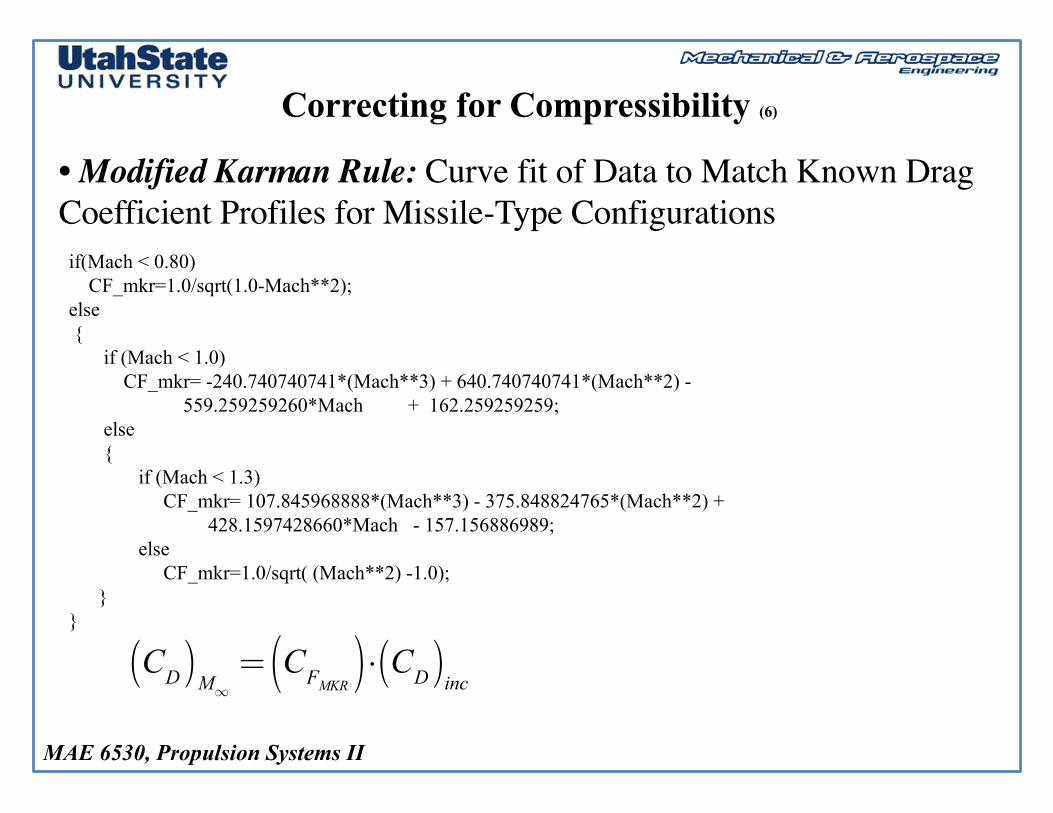
Correcting for Compressibility (6)
• Modified Karman Rule: Curve fit of Data to Match Known Drag Coefficient Profiles for Missile-Type Configurationsif(Mach < 0.80)
CF_mkr=1.0/sqrt(1.0-Mach**2);else{
if (Mach < 1.0)CF_mkr= -240.740740741*(Mach**3) + 640.740740741*(Mach**2) -
559.259259260*Mach + 162.259259259;else{
if (Mach < 1.3)CF_mkr= 107.845968888*(Mach**3) - 375.848824765*(Mach**2) +
428.1597428660*Mach - 157.156886989;else
CF_mkr=1.0/sqrt( (Mach**2) -1.0);}
}
CD( )M∞= CFMKR( )⋅ CD( )
inc
MAE 6530, Propulsion Systems II
Correcting for Compressibility (7)
Subsonic CDVaries as …
Supersonic CDVaries as …
MAE 6530, Propulsion Systems II
Example Calculation
MAE 6530, Propulsion Systems II
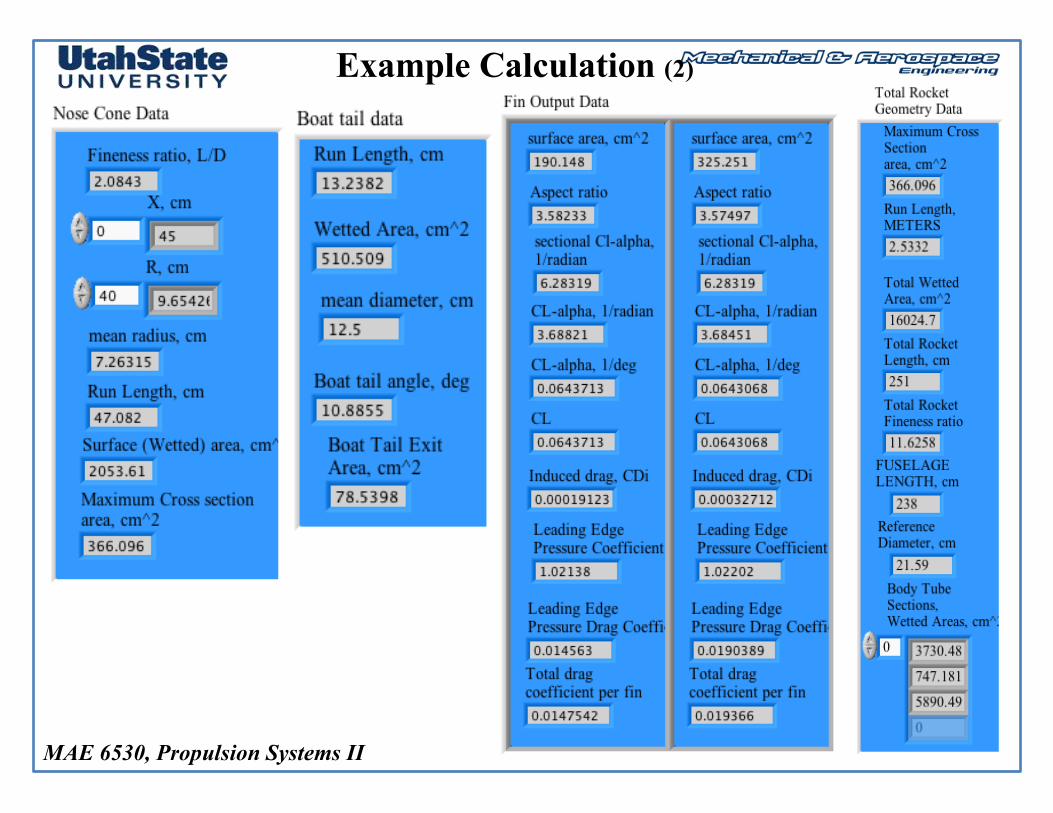
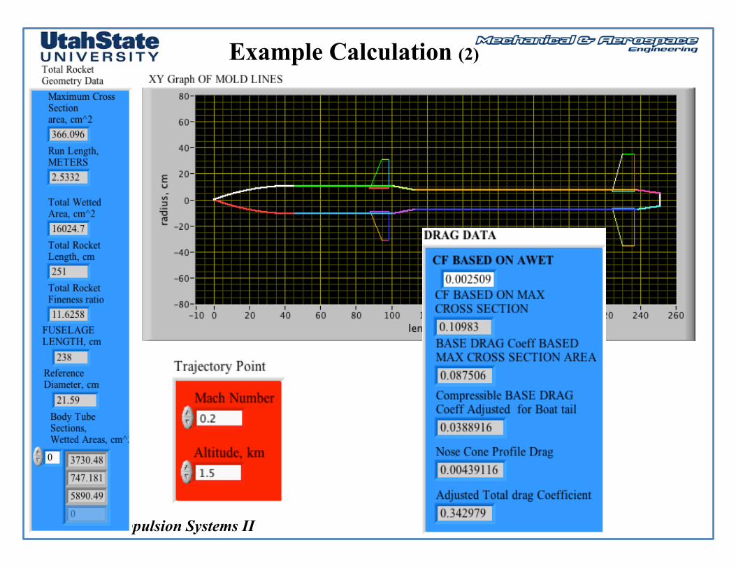
Example Calculation (2)
MAE 6530, Propulsion Systems II
Example Calculation (2)
MAE 6530, Propulsion Systems II
Higher Fidelity Codes
30
• Missile DATCOM is a widely used semi-empirical datasheet component build-up method for the preliminary design and analysis of missile aerodynamics and performance. It has been in continual development for over twenty years, with the latest version released in March 2011
• DATCOM has traditionally been supplied free of charge by the United States Air Force to American defense contractors. The code is considered restricted under International Traffic in Arms Regulations (ITAR) and can not be distributed outside the United States.
• Use of latest release by NON-USA Nationals Requires Special Export Licensing Permissions.