S Unité de R&D Décodeurs et Télévision Decoders and TV Sets Engineering Unit Réf. : 3000108848 R18 000-01 Auteur : Service Client NOTICE TECHNIQUE /TECHNICAL NOTICE for the AXIUM HD-D45 EU Document E / E Document DIFFUSION RESTREINTE.dot Page 1/46
Transcript
S Unité de R&D Décodeurs et Télévision Decoders and TV Sets Engineering Unit
Réf. : 3000108848 R18 000-01
Auteur : Service Client
NOTICE TECHNIQUE /TECHNICAL NOTICE for the AXIUM HD-D45 EU
Document E / E Document DIFFUSION RESTREINTE.dot Page 1/46
S Unité de R&D Décodeurs et Télévision Decoders and TV Sets Engineering Unit
1.2. DLP Technology .........................................................................................................................................6 1.2.1. Principle ............................................................................................................................................6 1.2.2. Tri-LCD : ...........................................................................................................................................7 1.2.3. Comparison between the 2 technologies .........................................................................................7
1.3. Functioning principle of a retroprojector ................................................................................................8 1.4. Architecture of the AXIUM ..........................................................................................................................9
2. GENERAL SYNOPSIS.....................................................................................................................................10 2.1. Cards Interconnection ..............................................................................................................................10
3. BREAKDOWN DIAGNOSIS DIAGRAM ...............................................................................................10 3.1. Front panel LED : ...................................................................................................................................10 3.2. General Diagram : ..................................................................................................................................12 3.3. Diagram A : Power problems ..................................................................................................................13 3.4. Diagram B : .............................................................................................................................................14 3.5. Diagram C : OSD Functionning Problems ..............................................................................................15 3.6. Diagram D : .............................................................................................................................................16 3.7. Diagram E : ...............................................................................................................................................17 3.8. Diagram F:...............................................................................................................................................18
4. DISASSEMBLING MODULES PROCESS.......................................................................................................19 4.1. Necessary tools.......................................................................................................................................19 4.2. Disassembling of the card door............................................................................................................19 4.3. Disassembling of the Mainboard card ......................................................................................................20
4.3.1. Removal of the back plate ..........................................................................................................20 4.3.2. Removal of the mainboard and its protection .............................................................................21
4.4. Disassembling of the power supply ..........................................................................................................22 4.4.1. Removal of the back plate ..........................................................................................................22 4.4.2. Removal of the « power support / power supply » unit ..................................................................23 4.4.3. Removal of the power card from its support...................................................................................24
4.5. Disassembling of the power supply's ballast ............................................................................................24 4.5.1. Removal of the back plate ..........................................................................................................24 4.5.2. Access to the main power supply ..............................................................................................24 Cf §4.4.2 : Removal of the « power support / power supply » unit ...........................................................24 4.5.3. Removal of the « ballast support / ballast » unit...........................................................................25
4.6. DIsassembling of the AMPLIFIER/TUNER card.......................................................................................28 4.6.1. Removal of the right trap ............................................................................................................28 Cf ; 4.3.1 : Removal of the back plate ......................................................................................................28 4.6.2. Removal of the door /door card unit............................................................................................28 4.6.3. Removal of the amplifier/tuner unit ..............................................................................................29 • Removal of the 2 female lugs ..........................................................................................................29
4.7. Disassembling of the LED card ................................................................................................................30 4.7.1. Removal of the back plate ..........................................................................................................30 4.7.2. Removal of the bass box .............................................................................................................30 4.7.3. Removal of the LED card ...........................................................................................................31
4.8. DIsassembling of the formater card..........................................................................................................32
Document E / E Document DIFFUSION RESTREINTE.dot Page 2/46
4.8.1. Removal of the back plate ..........................................................................................................32
S Unité de R&D Décodeurs et Télévision Decoders and TV Sets Engineering Unit
Réf. : 3000108848 R18 000-01
Auteur : Service Client 4.8.2. Removal of the bass box .............................................................................................................32 4.8.3. Removal of the external speakers ..............................................................................................32 4.8.4. Removal of the optic chamber and the frame 4.8.5. Removal of the optical engine ...................................................................................................34
5. FUNCTIONNING TESTS OF THE AXIUM AMONG CUSTOMERS AFTER INTERVENTION.......................41 6. MIRROR SET UP (FRONT ACCESS) .........................................................................................................42
6.1. Action on the 3 set up screws...................................................................................................................43 7. SOFTWARE UPDATE ................................................................................................................................44 8. SPARE PARTS..............................................................................................................................................45
Document E / E Document DIFFUSION RESTREINTE.dot Page 3/46
S Unité de R&D Décodeurs et Télévision Decoders and TV Sets Engineering Unit
Réf. : 3000108848 R18 000-01
Auteur : Service Client
1. AXIUM PRESENTATION
2. TECHNICAL CHARACTERISTICS
2.1.1. Main Characteristics :
• Very good luminosity : 700 cd/m2 • A real Contrast : 3000 :1 (deep black, bright colors, astonishing reliefs) • Technology DLPTM • Very high image resolution : 1 million pixels by color • Treatment of the DCDITM Faroudja's image • Flat Screen, anti-glare, important viewing angle • High definitionTV (1080i and 720p) • Image resolution : 1280 x 720 pixels • 8 video inputs • 2 PC inputs • 2 tuners • 1 HiFi output, 1 HiFi input and 1 digital output • "All in one" concept • "Table Top" design • Depth : 34cm • Weight : 25Kg • Matching Stand available as an option • 5 image set up modes • 9 image formats : 4/3, 14/9, 16/9, CINEMA, STRETCH, SUBTITLES, SCOPE, NATIF, AUTO • PIP (Picture In Picture), PAP (Picture And Picture), PAT (picture and text) • Teletext • Program electronic guide (EPG)
Audio Maximum power: 2 x 30W . Number of speakers : 4 Equalizer 5 bandwidths Lateral right door AV6 Input S-video (Mini Din 4-pin) Composite Input (1x RCA) Audio input(2 x RCA) PC1 VGA Computer input (subD 15-pin) Audio input(1xjack 3.5) Headphones 1 output (jack 3.5) 6 keys ( P+, P-, V+, V-, Stby, OK) 3 indicators with light (on/off, lamp, temperature) Rear Connections AV 1 (RGB/Comp./S-video, audio) AV 2 (RGB/Comp./S-video, audio) AV 3 (RGB/Comp./S-video, audio) AV4 S-video input (Mini Din 4-pin) Composite video input (1x RCA) Audio In input (2 x RCA) AV5 input Y, Pr, Pb In ( 3x RCA) interlaced / progressive Audio input (2 x RCA) Hi-fi Audio output ( 2x RCA)
Document E / E Document DIFFUSION RESTREINTE.dot Page 4/46
S Unité de R&D Décodeurs et Télévision Decoders and TV Sets Engineering Unit
Réf. : 3000108848 R18 000-01
Auteur : Service Client SPDIF Digital audio input Digital audio output PC2 DVI-D input Audio input (2x RCA) Input Signals Video signal: Native/Upscale: SDTV/EDTV (480i/480P)(576i/576P) HDTV ( 1080i/720P) Computer signal: Native/Upscale: VGA 640x480 SVGA 800x600 XGA 1024x768 , standard VESA (1152*864) Power supply AC 220-240 V ~50 Hz Maximum consumption. 300 W Stand-by 5 W
Dimensions and weight Dimensions (h x l x d): 791 x 1287 x 372 mm Weight 31 kg Dimensions and weight (packed) Dimensions (h x l x d): 858 x 1197 x 497 mm Weight : 38 kg Accessories Universal Remote controle URC-50 Batteries :2 x 1.5 V (type AA) Power cable with earth lug (European) Power cable with earth lug (UK) Power cable with earth lug (Italy) User Guide RF cable Connection Cables for Sound columns Fixing screws for Sound Columns Manipulation Gloves .
Document E / E Document DIFFUSION RESTREINTE.dot Page 5/46
S Unité de R&D Décodeurs et Télévision Decoders and TV Sets Engineering Unit
Réf. : 3000108848 R18 000-01
Auteur : Service Client
2.2. DLP Technology
2.2.1. Principle
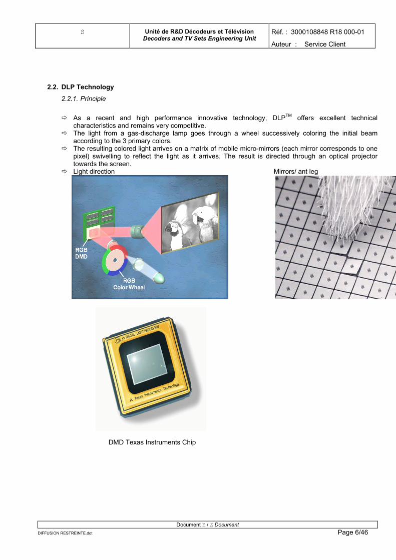
As a recent and high performance innovative technology, DLPTM offers excellent technical
characteristics and remains very competitive. The light from a gas-discharge lamp goes through a wheel successively coloring the initial beam
according to the 3 primary colors. The resulting colored light arrives on a matrix of mobile micro-mirrors (each mirror corresponds to one
pixel) swivelling to reflect the light as it arrives. The result is directed through an optical projector towards the screen. Light direction Mirrors/ ant leg
DMD Texas Instruments Chip
Document E / E Document DIFFUSION RESTREINTE.dot Page 6/46
S Unité de R&D Décodeurs et Télévision Decoders and TV Sets Engineering Unit
Réf. : 3000108848 R18 000-01
Auteur : Service Client 2.2.2. La technologie Tri-LCD :
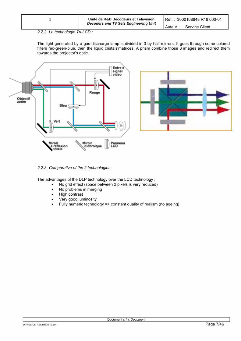
The light generated by a gas-discharge lamp is divided in 3 by half-mirrors. It goes through some colored filters red-green-blue, then the liquid cristals'matrices. A prism combine those 3 images and redirect them towards the projector's optic.
2.2.3. Comparative of the 2 technologies
The advantages of the DLP technology over the LCD technology :
• No grid effect (space between 2 pixels is very reduced) • No problems in merging • High contrast • Very good luminosity • Fully numeric technology => constant quality of realism (no ageing)
Document E / E Document DIFFUSION RESTREINTE.dot Page 7/46
S Unité de R&D Décodeurs et Télévision Decoders and TV Sets Engineering Unit
Réf. : 3000108848 R18 000-01
Auteur : Service Client 2.3. Functionning Principle of a projector
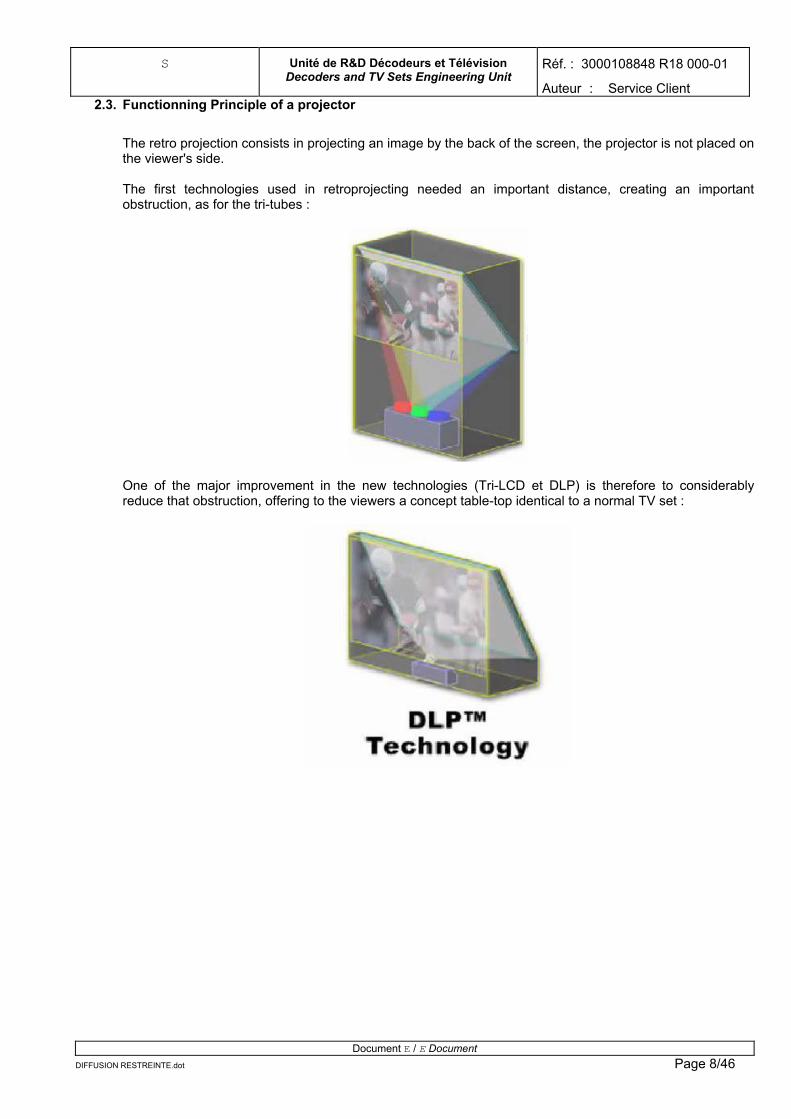
The retro projection consists in projecting an image by the back of the screen, the projector is not placed on the viewer's side. The first technologies used in retroprojecting needed an important distance, creating an important obstruction, as for the tri-tubes :
One of the major improvement in the new technologies (Tri-LCD et DLP) is therefore to considerably reduce that obstruction, offering to the viewers a concept table-top identical to a normal TV set :
Document E / E Document DIFFUSION RESTREINTE.dot Page 8/46
S Unité de R&D Décodeurs et Télévision Decoders and TV Sets Engineering Unit
Réf. : 3000108848 R18 000-01
Auteur : Service Client 2.4. AXIUM Achitecture
For the AXIUM, choice has been made to use 2 trapezoidal mirrors with 2 main advantages : • reduction of the product depth • possibility to set up the image geometry by acting on the « small » mirror with a completely
fixed optic.
Direction of light
Projector
Mirror
Mirror
screen
Document E / E Document DIFFUSION RESTREINTE.dot Page 9/46
S Unité de R&D Décodeurs et Télévision Decoders and TV Sets Engineering Unit
Réf. : 3000108848 R18 000-01
Auteur : Service Client
3. GENERAL SYNOPSIS
4. INTERCONNECTION OF THE CARDS
5. BREAKDOWN DIAGNOSE
5.1. Front panel LED :
The front panel's LED allow to get a first level of diagnose regarding the breakdown : A colored codWhen a probleoptical engine, Leds status :
State After powering (inOut of Stand-by pOn Step 1 of the StanStep 2 of the StanOut of Stand-by pof the lamp : 7500Out of Stand-by pthe lamp : 8000 h
Temperature of th
Temperature Form
Thermal Switch
Lamp Fan
DMD fan
Color Wheel
Lamp problem0
DIFFUSION RESTREINTE.d
Internal temperature light
Lamp indicator
Indicator on/off
e using the above indicators has been instaured in order to detect different types of breakdowns. m is detected, the TV set goes automatically in stand-by. Except in the case of an incident on the it is possible to reset the TV (for ex. :when the formater card temperature is back to normal).
Temperature Indicator Lamp indicator Stand-by Indicator stand-by) --- --- Fixed red hase --- --- Flashing Orange
--- --- Off d-by phase --- --- Flashing Green d-by phase --- --- Flashing Orange hase - Life duration hours
--- Flashing Red 10 seconds then Off
Flashing Orange
hase - life duration of ours
--- Flashing Red 10 seconds than Fixed Red for 5 seconds then shutdown
Flashing Orange
e optical engine Fixed Red --- Flashing Orange / fixed Red
ater Fixed Red Fixed Red Flashing Orange / Fixed Red
Fixed Red Fixed Red Flashing Orange / Fixed Red
Flashing Red Flashing Red Flashing Orange / Fixed Red
Fixed Red Flashing Red Flashing Orange / Fixed Red
--- Flashing Red Flashing Orange / Fixed Red
--- Flashing Red Flashing Orange / Fixed Red
Document E / E Document ot Page 10/46
S Unité de R&D Décodeurs et Télévision Decoders and TV Sets Engineering Unit
Réf. : 3000108848 R18 000-01
Auteur : Service Client
Document E / E Document DIFFUSION RESTREINTE.dot Page 11/46
S Unité de R&D Décodeurs et Télévision Decoders and TV Sets Engineering Unit
Réf. : 3000108848 R18 000-01
Auteur : Service Client
5.2. General Diagram :
Fin
Brancher la source audio en cause
Brancher l’antenne hertzienne
vous avez une image ?
Brancher la source en cause (autre
que tuner )
L’image hertzienne est elle correcte ?
Sortir de veille la télévision
La télécommande fonctionne t’elle ?
Le son est il correcte ?
La fonction OSD fonctionne ?
Appuyer sur le bouton On / Off
Oui
Oui
Oui
Oui
Oui
Oui
NonB. Problème sur la
télécommande
Non F. Problème sur le son
Non D. Problème d’affichage vidéo
Non E. Problème d’affichage du signal hertzien
Non C. Problème sur la fonction OSD
Non A. Problème d’alimentation La led d’alimentation est allumée ?
Début
Document E / E Document DIFFUSION RESTREINTE.dot Page 12/46
S Unité de R&D Décodeurs et Télévision Decoders and TV Sets Engineering Unit
Réf. : 3000108848 R18 000-01
Auteur : Service Client
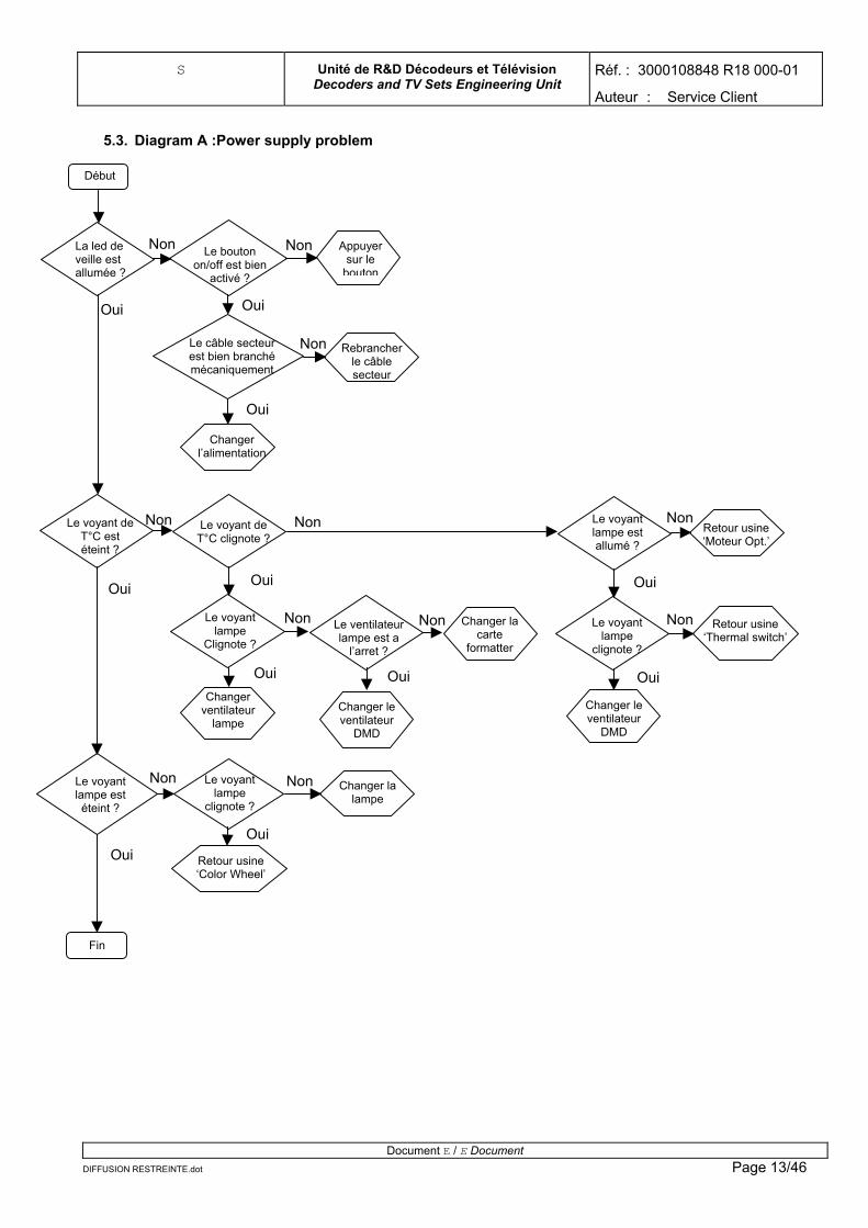
5.3. Diagram A :Power supply problem
Non
Non Non
NonNon Non
Non Non
Non
Non Non
OuiOui
Oui
Oui OuiOui
Oui Oui
Oui
OuiOui
Fin
Changer la lampe
Le voyant lampe
clignote ?
Changer la carte
formatter
Changer le ventilateur
DMD
Le ventilateur lampe est a
l’arret ?
Changer ventilateur
lampe Changer le ventilateur
DMD
Retour usine ‘Thermal switch’
Le voyant lampe
clignote ?
Retour usine ‘Moteur Opt.’
Le voyant lampe est allumé ?
Le voyant lampe est éteint ?
Le voyant de T°C est éteint ?
Retour usine ‘Color Wheel’
Le voyant de T°C clignote ?
Le voyant lampe
Clignote ?
Changer l’alimentation
Rebrancher le câble secteur
Le câble secteur est bien branché mécaniquement
Appuyer sur le
bouton
Le bouton on/off est bien
activé ?
La led de veille est allumée ?
Début
Document E / E Document DIFFUSION RESTREINTE.dot Page 13/46
S Unité de R&D Décodeurs et Télévision Decoders and TV Sets Engineering Unit
Réf. : 3000108848 R18 000-01
Auteur : Service Client
5.4. Diagram B :
Non
Non
Non
Oui
Oui
Oui
Fin
Changer la mainboard
Changer la carte led Vérifier sur la carte led que le Recepteur IR envoi des signaux
Changer la télécommande
Changer les piles
Début
Note : In order to access to the copper of the led card, unscrew the right trap of the TV set (2 screws).
Document E / E Document DIFFUSION RESTREINTE.dot Page 14/46
S Unité de R&D Décodeurs et Télévision Decoders and TV Sets Engineering Unit
Réf. : 3000108848 R18 000-01
Auteur : Service Client
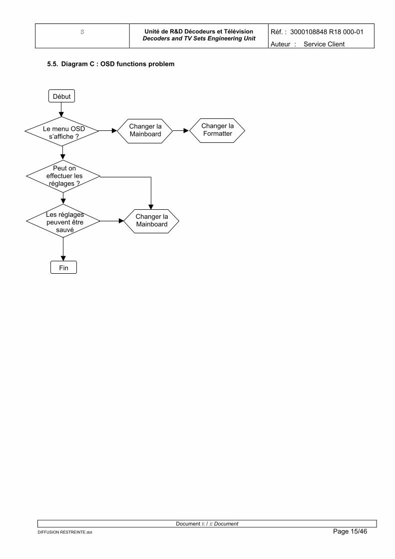
5.5. Diagram C : OSD functions problem
Début
Changer la Mainboard
Changer la Formatter
Le menu OSD s’affiche ?
Peut on effectuer les réglages ?
Les réglages peuvent être
sauvé
Fin
Changer la Mainboard
Document E / E Document DIFFUSION RESTREINTE.dot Page 15/46
S Unité de R&D Décodeurs et Télévision Decoders and TV Sets Engineering Unit
Réf. : 3000108848 R18 000-01
Auteur : Service Client
5.6. Diagram D :
Non Remplacer la Mainboard
t
DIFFUSION RESTREINTE.dot
débu
Non Y a t’il une
image ?
Non
Non
Oui
Oui
Remplacer la carte porte
Remplacez la Mainboard
Y a t’il une image ?
Vérifier la tenue mécanique du
cable MB_PT2
Branchez une source sur la mainboard
La source est connecté sur la
porte ?
Oui
La voie sub fonctionne ?
Oui
n
Non Reconnecté la
source La source est
bien connecté ?
Oui
Fi
Branchez une source sur une
péri telle
Document E / E Document Page 16/46
S Unité de R&D Décodeurs et Télévision Decoders and TV Sets Engineering Unit
Réf. : 3000108848 R18 000-01
Auteur : Service Client 5.7. Diagram E :
Non
Oui
Fin
Remplacez la Mainboard
Le scanning est sauvegarder
Rallumer la télévision
Effectuer un scanning
Remplacez la Carte ampli
Oui
Vérifier la tenue mécanique du cable MB_TU
Oui
Non Changer la source et re-tester
La source est valide ?
Mettre en veille la télévsion
Non Non
Oui Oui
Reconnecté la source
La source est bien connecté ?
Y a t’il une image ?
début
Document E / E Document DIFFUSION RESTREINTE.dot Page 17/46
S Unité de R&D Décodeurs et Télévision Decoders and TV Sets Engineering Unit
Réf. : 3000108848 R18 000-01
Auteur : Service Client
5.8. Diagram F:
La source est sur la carte
porte ?
Y ‘a t’il du son ?
Y ‘a t’il du son dans
le casque ?
Oui
Oui
Oui
Oui Brancher
une source audio sur péritel 1
Oui
Oui
Oui Oui
Non
Non
Non
Non
Non
Non
Non
Non Non
Désactiver la fonction
Connecter les câbles
Connecter la source
Fin
Changer la carte Ampli /
Tuner
Changer la Mainboard
Brancher le casque
Brancher une source audio sur
PC2
Changer la carte porte
Vérifier le cable
MB_PT2
Y ‘a t’il du son ?
La fonction Mute est
désactiver ?
Cables des haut-parleurs externes bien connectés ?
La source est bien
connecté ?
Changer les hauts parleurs
Le son est net et sans
bruits ?
Y ‘a t’il du son ?
Début
Document E / E Document DIFFUSION RESTREINTE.dot Page 18/46
S Unité de R&D Décodeurs et Télévision Decoders and TV Sets Engineering Unit
Réf. : 3000108848 R18 000-01
Auteur : Service Client 6. DISASSEMBLING MODULES PROCESS
Document E / E Document DIFFUSION RESTREINTE.dot Page 19/46
S Unité de R&D Décodeurs et Télévision Decoders and TV Sets Engineering Unit
Réf. : 3000108848 R18 000-01
Auteur : Service Client
• Disconnect the cable from the card door and its lug • Unscrew the 2 screws torx CBLX 3*8 • Remove the card
6.3. Removal of the Mainboard card
Câble « boutons » et sa cosse
Câble « audio / vidéo » et sa cosse
2 vis CBLX 3*8
6.3.1. Remove the back plate
1step : Remove the right trap
• see : 4.2 Removal of the card door 2 step : remove the left trap 3 step : Remove the right and left « corners »
Document E / E DocumenDIFFUSION RESTREINTE.dot
Tourner la vis plastique d’1/4 de tour et la retirer
t Page 20/46
S Unité de R&D Décodeurs et Télévision Decoders and TV Sets Engineering Unit
Réf. : 3000108848 R18 000-01
Auteur : Service Client
Document E / E Document DIFFUSION RESTREINTE.dot Page 21/46
• Remove 2*2 screws CBX4*12
Corner droit4 vis CBX 4*12 Corner droit
3 step : Remove the back plate
• Remove the 8 screws CBLX 3*12 from the RCA & scarts base plates • Remove the 2 hexagonal spacers of the DVI base plate • Remove the 3 screws CBX 4*12
3 vis CBX 4*12 8 vis CBLX 3*12
6.3.2. Removal of the mainboard and its shielding
S Unité de R&D Décodeurs et Télévision Decoders and TV Sets Engineering Unit
Réf. : 3000108848 R18 000-01
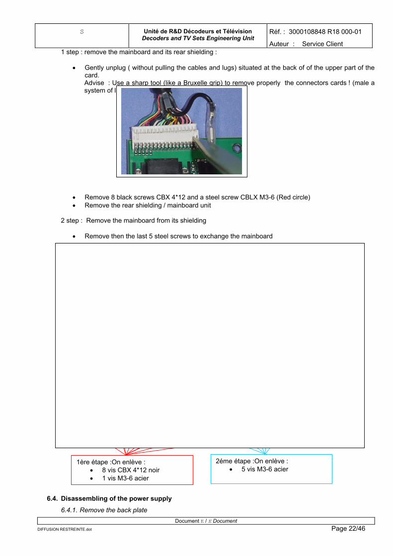
Auteur : Service Client 1 step : remove the mainboard and its rear shielding :
• Gently unplug ( without pulling the cables and lugs) situated at the back of of the upper part of the card. Advise : Use a sharp tool (like a Bruxelle grip) to remove properly the connectors cards ! (male a system of lever)
• Remove 8 black screws CBX 4*12 and a steel screw CBLX M3-6 (Red circle) • Remove the rear shielding / mainboard unit
2 step : Remove the mainboard from its shielding
• Remove then the last 5 steel screws to exchange the mainboard
Document E / E Document STREINTE.dot
2éme étape :On enlève : • 5 vis M3-6 acier
1ère étape :On enlève : • 8 vis CBX 4*12 noir • 1 vis M3-6 acier
6.4. Disassembling of the power supply
6.4.1. Remove the back plate
DIFFUSION RE Page 22/46
S Unité de R&D Décodeurs et Télévision Decoders and TV Sets Engineering Unit
Réf. : 3000108848 R18 000-01
Auteur : Service Client See : § 4.3.1 Removal of the back plate 6.4.2. Remove the « Power support / power supply » unit
• Remove the 4 screws CBX 4*12 • Gently pull the unit towards you until you're able to unwire (pay attention not to pull too much)
(Advise : start to unwire the upper cables)
Câble 2 pts vers le ballast
Câble des 2 switchs
Tresse vers support du ballast
Câble 9 pts vers carte Ampli/tuner
Câble 6 pts vers carte Formatter
Câble 10 pts vers Mainboard
Tresse vers goulotte (passe câble)
Tresse vers support moteur
4 Vis CBX 4*12
Document E / E Document DIFFUSION RESTREINTE.dot Page 23/46
Remark regarding the 2 connectors of the 2 switches : the 2 connectors can be permuted without problems
S Unité de R&D Décodeurs et Télévision Decoders and TV Sets Engineering Unit
Réf. : 3000108848 R18 000-01
Auteur : Service Client 6.4.3. Remove the power card from its support
• Remove the 7 screws CBLX M3-6 • Unplug the cable of the internal sector as well as the ground resumption lug.
Débrancher le câble du secteur interne
Débrancher le câble du secteur interne
Caution : Do not forget to put back the 3 male lugs on the card
6.5. Disassembling of the ballast power supply
6.5.1. Remove tha back plate
See : § 4.3.1 Removal of the back plate 6.5.2. Free the access to the main power supply
See : §4.4.2 : Removal of the « power supply support / power supply »
Document E / E Document DIFFUSION RESTREINTE.dot Page 24/46
S Unité de R&D Décodeurs et Télévision Decoders and TV Sets Engineering Unit
Réf. : 3000108848 R18 000-01
Auteur : Service Client
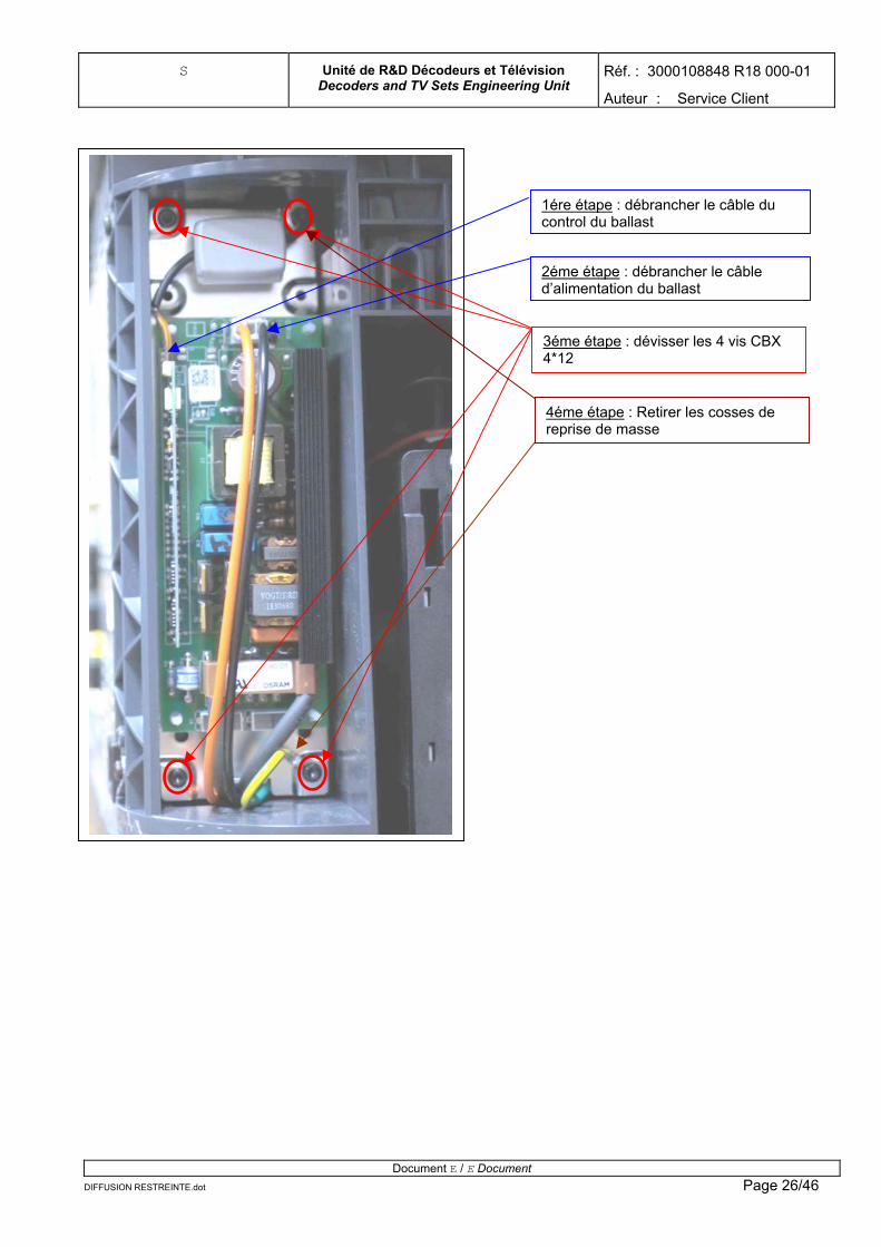
6.5.3. Removal of the « ballast support / ballast »
1step : Unclip the power lug of the lamp Gently press on the clip and pull the cable
Clip en plastique retenant le câble d’alimentation de la lampe
2 step : Remove the « ballast support / ballast unit »
• Unplug the ballast control cable and the power supply one • Remove the 4 screws CBX 4*12 • Remove the ground resumption lug • Remove the unit.
Document E / E Document DIFFUSION RESTREINTE.dot Page 25/46
S Unité de R&D Décodeurs et Télévision Decoders and TV Sets Engineering Unit
Réf. : 3000108848 R18 000-01
Auteur : Service Client
Document E / E Document DIFFUSION RESTREINTE.dot Page 26/46
4éme étape : Retirer les cosses de reprise de masse
2éme étape : débrancher le câble d’alimentation du ballast
1ére étape : débrancher le câble du control du ballast
3éme étape : dévisser les 4 vis CBX 4*12
S Unité de R&D Décodeurs et Télévision Decoders and TV Sets Engineering Unit
Réf. : 3000108848 R18 000-01
Auteur : Service Client 3 step : Unclip the card
• Usin
DIFFUSION RESTREINTE.dot
g a grip, unclip th
Ensemble support ballast / carte ballast
e card from its plastic studs
Document E / E Document Page 27/46
S Unité de R&D Décodeurs et Télévision Decoders and TV Sets Engineering Unit
Réf. : 3000108848 R18 000-01
Auteur : Service Client
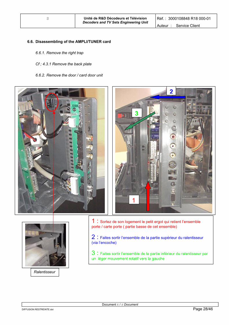
6.6. Disassembling of the AMPLI/TUNER card
6.6.1. Remove the right trap
Cf ; 4.3.1 Remove the back plate
6.6.2. Remove the door / card door unit
Ralentisseur
1 : Sortez de son logement le petit ergot qui retient l’ensemble porte / carte porte ( partie basse de cet ensemble)
2 : Faites sortir l’ensemble de la partie supérieur du ralentisseur (via l’encoche)
3 : Faites sortir l’ensemble de la partie inférieur du ralentisseur par un léger mouvement rotatif vers la gauche
3
2
1
Document E / E Document DIFFUSION RESTREINTE.dot Page 28/46
S Unité de R&D Décodeurs et Télévision Decoders and TV Sets Engineering Unit
Réf. : 3000108848 R18 000-01
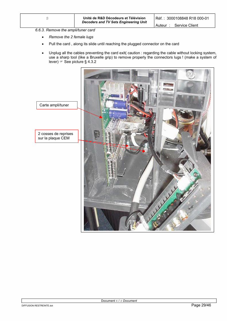
Auteur : Service Client 6.6.3. Remove the ampli/tuner card
• Remove the 2 female lugs
• Pull the card , along its slide until reaching the plugged connector on the card
• Unplug all the cables preventing the card exit( caution : regarding the cable without locking system, use a sharp tool (like a Bruxelle grip) to remove properly the connectors lugs ! (make a system of lever) See picture § 4.3.2
2 cosses de reprises sur la plaque CEM
Carte ampli/tuner
DIFFUSION RESTREINTE.dot
Document E / E Document Page 29/46
S Unité de R&D Décodeurs et Télévision Decoders and TV Sets Engineering Unit
Auteur : Service Client
Réf. : 3000108848 R18 000-01
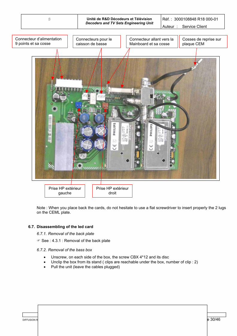
Note : When you place back the cards, do not hesitate to use a flat screwdriver to insert properly the 2 lugs on the CEML plate.
6.7. Disassembling of the led card
6.7.1. Removal of the back plate
See : 4.3.1 : Removal of the back plate 6.7.2. Removal of the bass box
• Unscrew, on each side of the box, the screw CBX 4*12 and its disc • Unclip the box from its stand ( clips are reachable under the box, number of clip : 2) • Pull the unit (leave the cables plugged)
Document E / E Document STREINTE.dot DIFFUSION RE Page 30/46
Connecteur d’alimentation 9 points et sa cosse
Connecteurs pour le caisson de basse
Connecteur allant vers la Mainboard et sa cosse
Prise HP extérieur gauche
Prise HP extérieur droit
Cosses de reprise sur plaque CEM
S Unité de R&D Décodeurs et Télévision Decoders and TV Sets Engineering Unit
Réf. : 3000108848 R18 000-01
Auteur : Service Client
Photos de l’un des 2 clips : ( les clips se situent sous le caisson de basse)
6.7.3. Remove the LED card
• Unplug the card Document E / E Document
DIFFUSION RESTREINTE.dot Page 31/46
S Unité de R&D Décodeurs et Télévision Decoders and TV Sets Engineering Unit
Réf. : 3000108848 R18 000-01
Auteur : Service Client • Remove it by slipering it along its rail
Carte led : siltué sur la partie en bas a droite de la télévision
6.8. Disassembling the formater card
6.8.1. Remove the back plate
See : 4.3.1 : Removal of the back plate 6.8.2. Remove the bass box
See : 4.7.2 : Removal of the bass box 6.8.3. Remove the external speakers
For an HP column :
• Remove the 4 CBX 4*12 screws retaining th
Document E / E DocumenDIFFUSION RESTREINTE.dot
La carte doit être dans être dans ses 2 glissières
e HP column
t Page 32/46
S Unité de R&D Décodeurs et Télévision Decoders and TV Sets Engineering Unit
Réf. : 3000108848 R18 000-01
Auteur : Service Client
6.8.4. Remove the optical chamber and the frame
Document E / E Document
DIFFUSION RESTREINTE.dot Page 33/46
S Unité de R&D Décodeurs et Télévision Decoders and TV Sets Engineering Unit
Réf. : 3000108848 R18 000-01
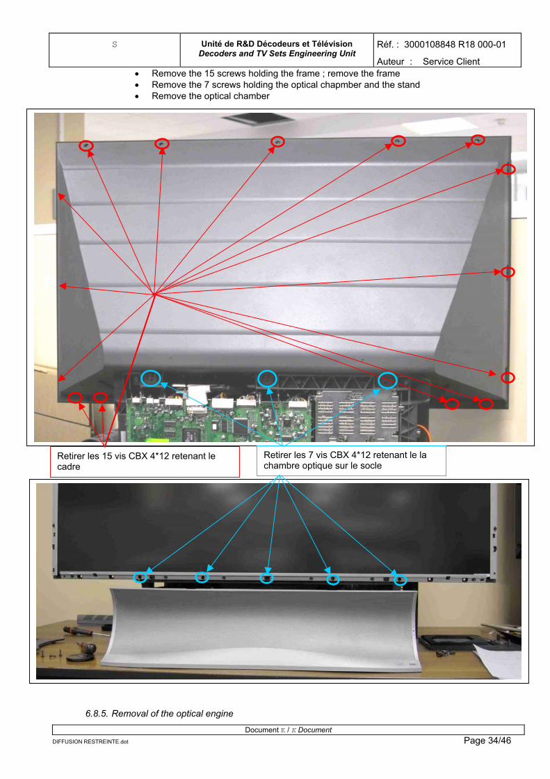
Auteur : Service Client • Remove the 15 screws holding the frame ; remove the frame • Remove the 7 screws holding the optical chapmber and the stand • Remove the optical chamber
Retirer les 7 vis CBX 4*12 retenant le la chambre optique sur le socle
Retirer les 15 vis CBX 4*12 retenant le cadre
6.8.5. Removal of the optical engine
Document E / E Document DIFFUSION RESTREINTE.dot Page 34/46
S Unité de R&D Décodeurs et Télévision Decoders and TV Sets Engineering Unit
Réf. : 3000108848 R18 000-01
Auteur : Service Client • Remove the neck ( 2vis CBX 4*12 – caution : do not forget to replace the braid from the power
supply when you assemble the TV) • Unplug all the cables that might prevent the optical engine's removal (see pictures) • Unplug the lamp connector ( See : 4.5.2 et 4.5.3 (1st part) • Remove the 4 screws CBX 4*12 (caution : do not forget to replace the power braid when you
assemble the TV) • Remove the optical engine
6.8.5.1. Remove the neck
Reprise de masse par tresse (tresse fixée via une cosse ronde et une rondelle
2 vis CBX 4*12 Goulotte
6.8.5.2. Remove all the cables preventing the exit
Document E / E Document
DIFFUSION RESTREINTE.dot Page 35/46
S Unité de R&D Décodeurs et Télévision Decoders and TV Sets Engineering Unit
Réf. : 3000108848 R18 000-01
Auteur : Service Client
Carte alimentation Carte Formatter Carte Ampli/tuner
On the ampli/tuner card, unplug the power cable
Câble d’alimentation
Document E / E Document DIFFUSION RESTREINTE.dot Page 36/46
S Unité de R&D Décodeurs et Télévision Decoders and TV Sets Engineering Unit
Réf. : 3000108848 R18 000-01
Auteur : Service Client On the Formater card, unplug :
• The Power cable • The DVI cable • The « ballast » cable
Document E / E Document DIFFUSION RESTREINTE.dot Page 37/46
S Unité de R&D Décodeurs et Télévision Decoders and TV Sets Engineering Unit
Réf. : 3000108848 R18 000-01
Auteur : Service Client • The Audio/video 34 points cable from the card door • The 32 points cable on the ampli/tuner card • The security cable • The power cable
Câble 32 points Câble 34 points Câble d’alimentationCâble de sécurité
6.8.5.3. Remove the engine
Document E / E Document DIFFUSION RESTREINTE.dot Page 38/46
S Unité de R&D Décodeurs et Télévision Decoders and TV Sets Engineering Unit
Réf. : 3000108848 R18 000-01
Auteur : Service Client
Ne pas oublier la reprise de masse sur le moteur
Retirer les 4 vis cbx 4*12 retenant le moteur sur le socle
Document E / E Document DIFFUSION RESTREINTE.dot Page 39/46
S Unité de R&D Décodeurs et Télévision Decoders and TV Sets Engineering Unit
Réf. : 3000108848 R18 000-01
Auteur : Service Client
6.8.5.4. Remove the formater card
• Remove the DMD fan (4 screws M4) • Remove the upper shielding( 4 screws M3 + 1 small column) • Remove the 4 screws
Ventilateur du DMD
Retirer les 4 vis M4 du ventilateur
Document E / E Document ION RESTREINTE.dot
DIFFUS Page 40/46
S Unité de R&D Décodeurs et Télévision Decoders and TV Sets Engineering Unit
Réf. : 3000108848 R18 000-01
Auteur : Service Client
1ére étape : retirer les 4 vis cruciform M3 retenant le radiateur sur le moteur
2éme étape : retirer les quatre entretoises retenant la carte sur le blindage
7. AXIUM FUNCTIONNING TESTS ON CUSTOMERS AFTER INTERVENTION
Document E / E Document DIFFUSION RESTREINTE.dot
Page 41/46
S Unité de R&D Décodeurs et Télévision Decoders and TV Sets Engineering Unit
Réf. : 3000108848 R18 000-01
Auteur : Service Client
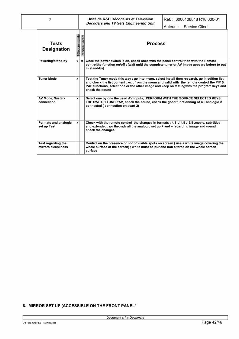
Tests Designation
Télé
com
man
de
Pan
neau
ava
nt
Process
Powering/stand-by x x Once the power switch is on, check once with the panel control then with the Remote controlthe function on/off ; (wait unitl the complete tuner or AV image appears before to put in stand-by)
Tuner Mode x Test the Tuner mode this way : go into menu, select install then research, go in edition list and check the list content ; exit from the menu and valid with the remote control the PIP & PAP functions, select one or the other image and keep on testingwith the program keys and check the sound
AV Mode, Syster-connection
x Select one by one the used AV inputs, .PERFORM WITH THE SOURCE SELECTED KEYS THE SWITCH TUNER/AV, check the sound, check the good functionning of C+ analogic if connected ( connection on scart 2)
Formats and analogic set up Test
x Check with the remote control the changes in formats : 4/3 ,14/9 ,16/9 ,movie, sub-titles and extended , go through all the analogic set up + and – regarding image and sound , check the changes
Test regarding the mirrors cleanliness
Control on the presence or not of visible spots on screen ( use a white image covering the whole surface of the screen) ; white must be pur and non altered on the whole screen surface
8. MIRROR SET UP (ACCESSIBLE ON THE FRONT PANEL°
Document E / E Document DIFFUSION RESTREINTE.dot Page 42/46
S Unité de R&D Décodeurs et Télévision Decoders and TV Sets Engineering Unit
Réf. : 3000108848 R18 000-01
Auteur : Service Client IMPORTANT : The mirror set up must be touched only after having installed definitely the axium 45 ‘’ on its stabilized stand with a maximum of flat. The aim is to abtain a geometry and correct framing. Location of the set up screws
Le réglage du miroir doit être effectuer avec une mire de test SAGEM via une source ayant une sortie DVI. La configuration a utiliser est un affichage 1280*720 à 60 Hz. Apres avoir affiché la mire, redimensionner l’image de tel façon que le cadre vert de la mire touche les bords de l’écran.
23
1
8.1. Action on the 3 set up screws
Screw N°1 : Shift the image according to a vertical axis.
Document E / E Document DIFFUSION RESTREINTE.dot Page 43/46
S Unité de R&D Décodeurs et Télévision Decoders and TV Sets Engineering Unit
Réf. : 3000108848 R18 000-01
Auteur : Service Client
Document E / E Document DIFFUSION RESTREINTE.dot Page 44/46
Screw N°2 : Shift the image according to a horizontal axis Screw N°3 : Increase or decrease proportionally the image
9. SOFTWARE UPDATE
S Unité de R&D Décodeurs et Télévision Decoders and TV Sets Engineering Unit
Réf. : 3000108848 R18 000-01
Auteur : Service Client In order to proceed to the software update, you must have the following elements :
• Interface box connecting to the input « service » of the machine. • 1 câble RS232 (including a DB9 male and a female) allowing to relate the PC to the interface box.
You can
10. SPARE PAR
10.1.Electro
10.2.Mecani
DIFFUSION RESTREINTE
Figure 1 : boîtier "interface"
then update the Software version thanks to the RSDIAG-SESAME program.
TS
nic cards list
CIE MainCIE AmpCIE FormCarte aliMPF430CIE carteBallast PCIE carte
Led/IR 251690631 T VIP 2AC/380 O1 251613577 connectique pre-serie 251703441
Document E / E Document Page 45/46
S Unité de R&D Décodeurs et Télévision Decoders and TV Sets Engineering Unit
Réf. : 3000108848 R18 000-01
Auteur : Service Client
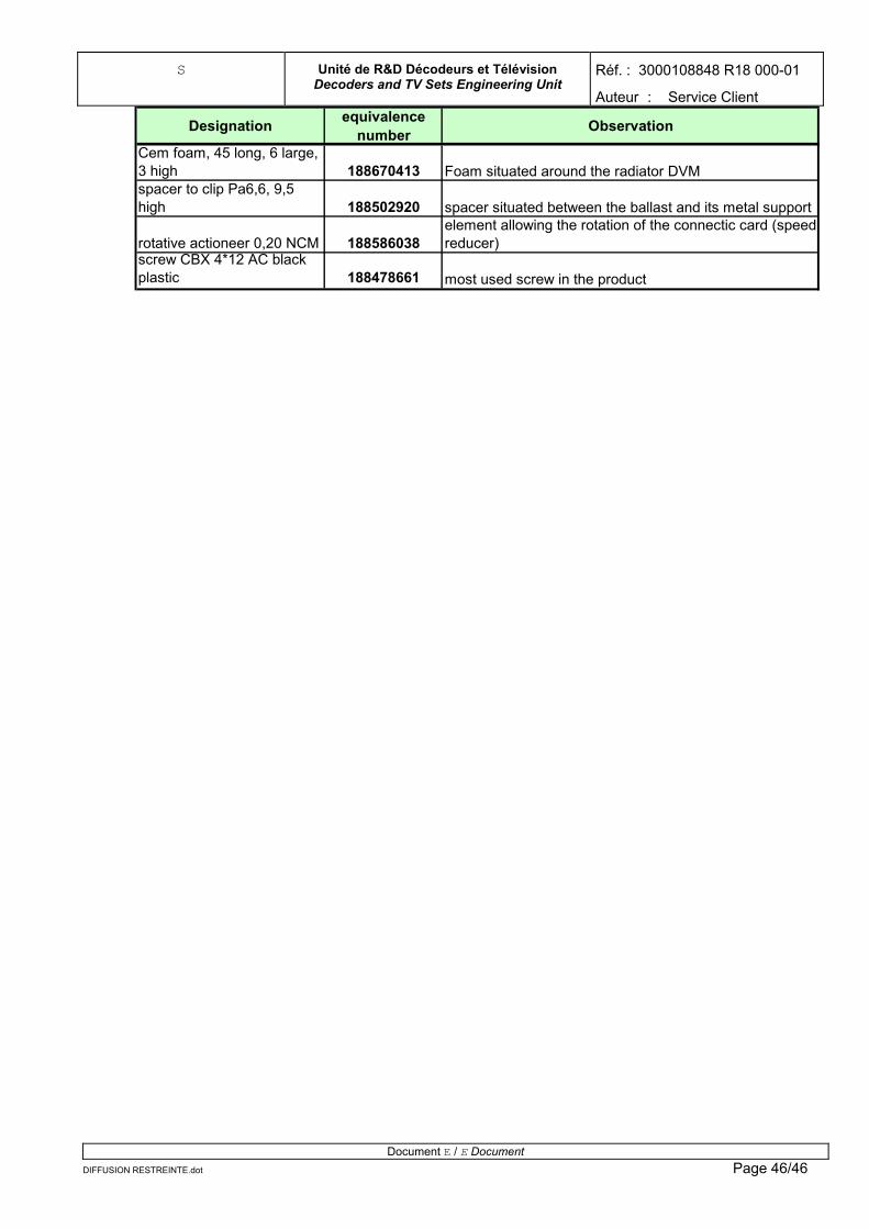
Designation equivalence number Observation
Cem foam, 45 long, 6 large, 3 high 188670413 Foam situated around the radiator DVMspacer to clip Pa6,6, 9,5 high 188502920 spacer situated between the ballast and its metal support
rotative actioneer 0,20 NCM 188586038element allowing the rotation of the connectic card (speed reducer)
screw CBX 4*12 AC black plastic 188478661 most used screw in the product
Document E / E Document DIFFUSION RESTREINTE.dot Page 46/46