Page 1
1st European Conference on Polygeneration
Novel steam engine for multi primary energy resources 281
NOVEL STEAM ENGINE FOR MULTI PRIMARY ENERGY RESOURCES
Peter Platell RANOTOR AB, Tilskogsvägen 15, 193 40 Sigtuna, Sweden, Phone +46 8
59252428 , Fax +46 8 592 591 60, e:mail [email protected]
ABSTRACT
In our daily live we are surrounded with different prime mover (power–cycles)
as internal combustion engines, jet engines and big power plant that propel vehicles
and generate electricity.
The oldest type of power cycles is the Rankine –cycle or as the more familiar
name, steam power. Steam power is today mainly used in large power plant
generating electricity by burning fossil fuel or splitting atoms in nuclear power plant.
When it comes to smaller steam power plant people in general associate steam
power with black smoking locomotive or slow boats. However, Rankine power cycles
has several inherent unique qualities that makes it very attractive as a future
propulsion system in mobile applications as well as small scale electric generation
and heat at the same time, so-called CHP (Combined Heat and Power).
Page 2
Tarragona (Spain), 16-17 October 2007
282 P. Platell (RANOTOR)
The novel high-tech micro Rankine cycle embodied as steam engine is not
only a choice of replacing conventional prime movers but may an also be an
attractive complement to an internal combustion engine, gas turbine and fuel cell
where waste heat is recovered and realising a hybrid power cycles with high
efficiency, flexibility and reliability. However, in many applications a self-contained
steam engine will offer the best possibility to use different energy sources including
solar energy,
This paper gives a brief description of the results from the work on a modern
steam engine that has been carried out by the RANOTOR Company and current
research work at KTH Stockholm. The figures in this paper is mainly based on
computer simulation models but also on certain laboratory tests on specific
components
INTRODUCTION - WHY STEAM ENGINE AGAIN-
Among different types of power cycles the steam power cycles ( Rankine
cycle) unfolds the largest possibilities to use various primary energy resources. As
long there is a heat sources above + 400 ºC it is possible to boil water and then
generate electricity. At present the dominating power cycles for small-scale power is
the conventional internal combustion engine.
External combustion has a more fuel flexible power cycle than internal
combustion engine because the fuel doesn’t have to deal with anti-knocking and
lubrication issues. Internal combustion is also more sensitive for fouling problem than
an external combustion with heat transfer to the working fluid via a heat exchanger.
Steam power is not unique when it comes to external combustion. However,
steam power is unique when it comes to external combustion and low temperature.
The external combustion in a steam engine starts at ambient temperature whereas a
Stirling engine for instance uses a preheating process in order to get acceptable
efficiency. That means that the highest flame temperature in a steam power system
Page 3
1st European Conference on Polygeneration
Novel steam engine for multi primary energy resources 283
is low and hence very little nitrogen in the air is oxidize. RANOTOR company has
previous carried out testing and evaluation of combustion performance and
emissions for a steam engine. The result has been compared with other engines and
particular with the Stirling engine. The ability to harness low temperature makes the
steam power also able to recovery waste heat from other sources and acting as a
so-called bottoming cycle.
Last but not least, the ability to use of low temperature sources makes it
possible to harness solar energy by evaporating water or other working fluids in
parabolic trough. Stirling engine requires about + 800 ºC to operate which requires
high concentrating solar collectors, which in turn means complex and expensive
solar collector technology, whereas steam power can accept lower temperature and
thus simpler and cheaper solar collectors. When generating electricity from solar
energy in this way it is called STP (Solar Thermal Power). Such a solar thermal
power system has run for a long time in California dessert but now there is
resurgence in this technology and approximately 3000 MW new capacities is under
construction.
NOVEL STEAM ENGINE SYSTEM TECHNOLOGY
In Figure 1 the components in a novel steam engine system are illustrated.
The components are the same as in big power plant and old classic steam engine
system; A burner, steam generator, an expander, a condenser and a feed pump.
Burners will be different depending on fuel. Alcohols can be pre-vaporized
with the heat from the condenser and pre-mixed and resulting in very low content of
harmful emissions in the exhaust gas [1].
The most costly components in the system are the steam generator (boiler)
and the expander. In a typical steam power plant the cost normalised to the electric
output for the steam generator is about twice the expander. Due to the high cost and
Page 4
Tarragona (Spain), 16-17 October 2007
284 P. Platell (RANOTOR)
weight for conventional boilers there is a necessity to find a new steam generator
design whith high compactness.
In order to realise compact steam generators in terms of volume and specific
weight it is necessary to adopt laminar flow on the flue gas side. Heat transfer
coefficient is proportional to Nusselt number (Nu), heat conductivity λ and reciprocal
hydraulic diameter (d) according to following equation:
dNu λα ⋅=
Figure .1 Components in a steam engine system
Expander
Auxiliary System
Condenser System
Steam Generation System
AM Auxiliary Steam Motor�AP Air Pump�BP Fuel Pump�BR Burner�CB Condenser Bufffer�CD Condenser (air cooled)�EX Main steam motor�FP Feed Pump�SB Steam Buffer�SG Steam Generator�
Page 5
1st European Conference on Polygeneration
Novel steam engine for multi primary energy resources 285
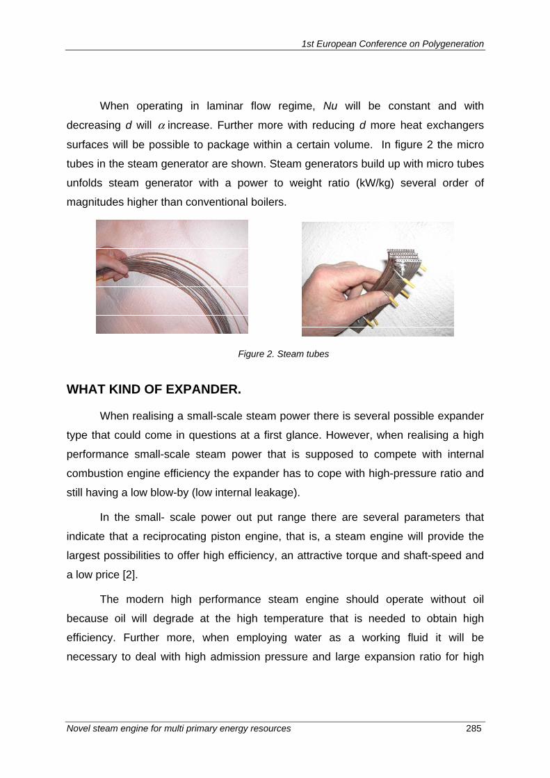
When operating in laminar flow regime, Nu will be constant and with
decreasing d will α increase. Further more with reducing d more heat exchangers
surfaces will be possible to package within a certain volume. In figure 2 the micro
tubes in the steam generator are shown. Steam generators build up with micro tubes
unfolds steam generator with a power to weight ratio (kW/kg) several order of
magnitudes higher than conventional boilers.
Figure 2. Steam tubes
WHAT KIND OF EXPANDER.
When realising a small-scale steam power there is several possible expander
type that could come in questions at a first glance. However, when realising a high
performance small-scale steam power that is supposed to compete with internal
combustion engine efficiency the expander has to cope with high-pressure ratio and
still having a low blow-by (low internal leakage).
In the small- scale power out put range there are several parameters that
indicate that a reciprocating piston engine, that is, a steam engine will provide the
largest possibilities to offer high efficiency, an attractive torque and shaft-speed and
a low price [2].
The modern high performance steam engine should operate without oil
because oil will degrade at the high temperature that is needed to obtain high
efficiency. Further more, when employing water as a working fluid it will be
necessary to deal with high admission pressure and large expansion ratio for high
Page 6
Tarragona (Spain), 16-17 October 2007
286 P. Platell (RANOTOR)
efficiency [ 2]. Typical expansion ratios for internal combustion engine are 1:10-1:20
whereas the steam engine should have an expansion ratio of 1:100.
High Pressure means a high-density working fluid, which in turn means a
high-speed nature of the engine.
When realising a high-speed steam engine several advantages are possible
to achieve. High speed will give reduced internal leakage (Blow-by) and hence,
improved efficiency. Further more, high-speed will imply low heat losses and last but
not least, high specific power (kW/kg). High specific power is of paramount
importance in all utomotive applications, but will also give more cost effective
stationary applications.
Steam engine is used to be associated with large and bulky contraption but
with modern concept it has an inherent quality to be very compact and having much
higher power density than internal combustion engine. This is because it’s possible
to fill almost all the displacement volume with working fluid before expanding. In
figure 3 is a computer simulated pressure volume graph illustrated. It can be seen
that the area, which correspond to the work during one power cycle is big, i.e. mean
effective pressure is high compared to an internal combustion.
In Figure 3 is also illustrated a computer simulated pressure –volume graph
for a steam engine acting in a reversed mode, that is, compressing steam instead of
expanding steam and hence providing a negative torque. In such a mode is the
steam engine providing a powerful engine braking, which is an attractive feature in
automotive applications. When it is possible to operate a steam engine with high
shaft speed combine with high torque, very high specific power can be possible to
obtain.
In Figure 4 the specific power versus shaft speed is illustrated. It can be seen
that specific power of 1200 kW/litre displacement volume should be possible to
obtain. That is more than ten times higher power density than a typical internal
combustion engine
Page 7
1st European Conference on Polygeneration
Novel steam engine for multi primary energy resources 287
Pressure – volume graph (Indicator diagram)
Figure 4. Specific power kW per litre displacement volume
N
Page 8
Tarragona (Spain), 16-17 October 2007
288 P. Platell (RANOTOR)
With supercritical steam engine employing a pressure of 250 bar and a
mechanical design that can operate at high pressure it could be possible to get very
high performance including an torque characteristic that is considered as favourable
in automotive applications. In Figure 5 the torque characteristic for an internal
combustion engine and a steam engine is schematic illustrated. The torque for the
steam engine is very high already from zero shaft -speed and has a torque
characteristic that increase with decreasing shaft speed.
Figure 5. Schematic torque characteristics for a high speed steam engine and an ICE
The internal combustion requires a shaft speed of 500-1000 rpm (idling)
before any torque is obtained at all. The torque is then increased until maximum
torque is reach whereupon the torque is reduced at higher shaft speed. The steam
engine torque characteristic makes it possible to eliminate or at least using a very
simple and cheap gear-box in automotive applications.
As shown in figure 4 and 5 is the shaft speed very high compared to old
classic steam engines that revs a few hundreds revolution per minute It is clear that
a moderns steam engine will benefit very much with high shaft-speed. In Figure 6 the
efficiency for a steam engine is illustrated as function of shaft speed and for two
simulations cases, one where only friction losses is taking into account and one case
where also heat losses and blow-by is taking into account. It can be seen that the
Page 9
1st European Conference on Polygeneration
Novel steam engine for multi primary energy resources 289
efficiency is not affected very much by shaft speed whereas heat losses and blow-by
is strongly influenced by shaft speed.
Engines performance can be presented in so-called performance maps. In
Figure 7 such a performance maps based on computer simulation is illustrated. The
performance maps have shaft-speed on the x-axis and torque on y-axis. The
efficiency curve is then plotted in the graph and constant efficiency curves looks
more and less like island as can be seen in Figure 7. It is also apparent the highest
efficiency is obtained at low loads, that is, low torque. This is the opposite to
conventional internal combustion engine which have the highest efficiency at full or
close to full load. The efficiency characteristic of a steam engine is very advantages
in most applications.
In a typical car the maximum power out put is many times higher than the
significant power used during normal driving. There is a desired (need) for high peak
power during very short periods but on average is the power out put in the order of
10-20 times lower than peak power. That holds also true in stationary applications
where the steam engine is used for combined heat and electricity generation. Normal
power electricity output in a typical building is about one tenth of the required peak
power.
Figure 6. Efficiency as a function of shaft speed
Page 10
Tarragona (Spain), 16-17 October 2007
290 P. Platell (RANOTOR)
Figure 7. Performance maps for a 100 bar and a 250 bar steam engine.
In figure 7 shows the performance maps for two different admission data
(pressure and temperature). One is for supercritical steam at 250 bar and one is for
100 bar. The efficiency for 250 bar machine is slightly higher with the chosen
temperature, but torque will differ very much. A steam engine employing high
pressure resembles hydraulic motors. However, in the steam engine case should
shaft speed be considerably higher. The basic physics that tells us that a modern
high performance steam engine should operate with high pressure, high shaft speed
and operation without oil as lubricants calls for extraordinary engine design.
One concept that seams to offer the desired requirements is a multi cylinder
axial machine with wobble plate (Taumelscheibengetriebe) and a rotating valve as
illustrated in Figure 8.
Torque [Nm/liter] Torque [Nm/liter]
rpm rpm
Page 11
1st European Conference on Polygeneration
Novel steam engine for multi primary energy resources 291
.
Figure 8 Axial multi piston steam engine
Multi cylinder will give low degree of irregularity of torque and hence a smooth
operating characteristic (turbine like). Low degree of irregularity of torque is
favourable because it makes it possible to operate the steam engine at low speed
without feeling torque pulsation. The wobble plate concept gives several possibilities
for attractive balancing solutions and hence free of vibrations. Further more, very low
transverse forces on piston, which gives low friction losses. An axial piston engine
also makes it easy to implement a rotating valve in the centre, which unfolds very
high-shaft speed and hence low blow-by and heat losses (high efficiency) and high
specific power. Rotating valve imply a simple cut –off (capacity control) for both
forward and backward (regenerative braking). Axial machines with a rotating valve
makes it turn possible to built engine with short inlet pipes with equal length that is, a
small clearance volume (dead space), which in turns imply high expansion ration and
high efficiency.
Page 12
Tarragona (Spain), 16-17 October 2007
292 P. Platell (RANOTOR)
CO2 STEAM ENGINE
If temperature sources is below approximately +400 C water as a working
fluid will not yield the best thermodynamic characteristic when it comes to high
efficiency and so-called ORC (Organic Rankine Cycles) is gaining increasing interest
to recover low grade waste heat. Such a ORC is using refrigerants as working fluid
rather than water. Due to environmental concern natural working fluids as CO2,
ammonia and propane have been suggested as the next generation working fluid in
AC and refrigerators. An interesting concept is to implement a so-called transcritical
power cycles employing CO2 as working fluid [Yang]. If using CO2 as a working fluid
the heat sink has to be lower than for water as working fluid. The schematic different
temperature level for a CO2 and water Rankine cycle is illustrated in a temperature-
entropy diagram, Figure 9.-
H2O
CO2
+ 400 ºC
+ 200 ºC
+ 100 ºC
+ 20 ºC
T
H2O
CO2
+ 400 ºC
+ 200 ºC
+ 100 ºC
+ 20 ºC
T
Figure 9. Typical temperature-entropy diagram H2O and CO2 Rankine cycle
In Figure 10 is efficiency for a CO2 steam engine illustrated as function of inlet
temperature (admission temperature) for different inlet pressure (admission
pressure). With a low condensing temperature (+22 ºC) the efficiency can be pretty
high even for low admission temperature. The lower temperature the simpler and
cheaper solar collectors can be used. Even at as low temperature as +175 ºC the
efficiency (electric) is in the same order of a photovoltaic. However, with a solar
Page 13
1st European Conference on Polygeneration
Novel steam engine for multi primary energy resources 293
powered CO2 steam engine it is possible to burn some local fuel when sun is failing
and hence, a solar thermal CO2 steam engine will be able to offer dispatchable
energy commodities.
Figure 10. Efficiency for a CO2 steam engine
The CO2 steam engine also makes it possible to realise an innovative power-
heat pump that besides acting as a power cycle and generating electricity and heat it
also can operate in the reversed mode as a heat pump. Mostly working fluid is not
well suited for operation both in a power cycle and as a heat pump or AC. Heat
pumps with CO2 as a working fluid has been in commercial use in Japan for many
years. CO2 heat pumps offer high efficiency for hot water production if certain
condition is present. In Figure 11 is a CO2 steam engine operating with solar energy
or by burning a fuel. The steam engine generates electricity and low-grade heat.
Electricity is used to propel the heat pump that produces low temperature for
freezing applications and and hot water.
Page 14
Tarragona (Spain), 16-17 October 2007
294 P. Platell (RANOTOR)
Low-grade heat (+20°C) for storing in the ground, for direct supply of heat to the double-slot building envelope, or for hot water (+60°C)
5-kW electricity or drive of compressor
Solar and/or Fuel
Steam
Space-cooling, refrigeration, deep-
freezing
Hot water
Steam
CONCLUSION
The research so far indicates that there are great possibilities to improve cost
and performance of steam engine system for small-scale CHP applications. The
most attractive expander seams to be the reciprocating piston engine but further
development of the high-speed oil-free steam engine has to carried out before a
mature and reliable engine is commercial technology for automotive applications. For
stationary applications the situation is different because specific weight is not a
crucial parameters. Besides the oil-free topic also fast valve mechanism is important
to realise in order to obtain the performance described in this paper.
Page 15
1st European Conference on Polygeneration
Novel steam engine for multi primary energy resources 295
ACKNOWLEDGMENTS
Many thanks to the Foundation For Strategic Environmental Research,
Sweden that is funding current research project at KTH, High-Tech Steam Engine,
RANOTOR Company and to Licentiate Yang Chen at KTH, who performed the
efficiency simulation of the CO2 Rankine cycle.
REFERENCES
Ref 1. Rolf Egnell, Rolf Gabrielsson, Alternative engine , Info nr. 829-1991
NUTEK Sweden
Ref 2. Peter Platell, Displacement expanders for small-scale cogeneration,
Licentiate thesis Department of Machine Design Royal Institute of
Technology, 1993, Stockholm
Ref 3 Y. Chen, P. Lundqvist, P Platell, 2005. Theoretical Research of Carbon
Dioxid Power Cycle Applications in Automobile Industry to Reduce Vehicle’s
Fuel Consumption, Applied Thermal Engineering, 25.
Ref 4 Chen, Y., 2006. Novel Cycles Using Carbon Dioxide as Working Fluid.
Licentiate Thesis, Energy Technology, KTH, Sweden.