26
NTPC BADARPUR Seminar Presentation Prepared By: 1.Atul Anand 2.Keshav Rheja 3.Raghav Chaudhary 4.Rajdeep Das 5.Shikhar Agarwal 6.Vishal Varshney
| Date post: | 19-Feb-2017 |
| Category: |
Documents |
| Upload: | shikhar-agarwal |
| View: | 86 times |
| Download: | 0 times |

NTPC BADARPURSeminar Presentation
Prepared By:1.Atul Anand
2.Keshav Rheja3.Raghav Chaudhary
4.Rajdeep Das5.Shikhar Agarwal6.Vishal Varshney

About NTPC• 10th largest power generator in
the world, 3rd largest in asia.• Total capacity = 43108 MW.• Largest power company in India.
Contributes 25.6% power with only 16% installed capacity.
• Vision: To be one of the world’s largest and best power utilities,powering India's growth.
• Mission:“Develop and provide reliable power, related products and services at competitive prices, integrating multiple energy sources with innovative and eco-friendly technologies and contribute to society.”
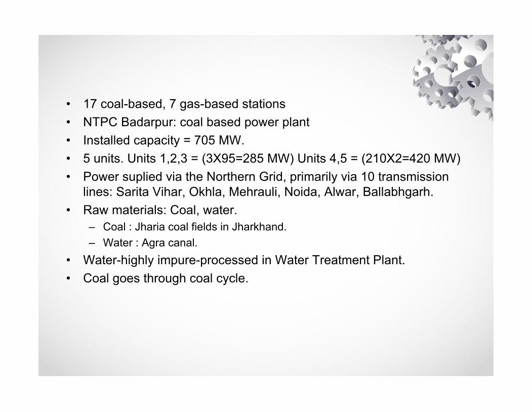
• 17 coal-based, 7 gas-based stations• NTPC Badarpur: coal based power plant• Installed capacity = 705 MW. • 5 units. Units 1,2,3 = (3X95=285 MW) Units 4,5 = (210X2=420 MW)• Power suplied via the Northern Grid, primarily via 10 transmission
lines: Sarita Vihar, Okhla, Mehrauli, Noida, Alwar, Ballabhgarh.• Raw materials: Coal, water.
– Coal : Jharia coal fields in Jharkhand.– Water : Agra canal.
• Water-highly impure-processed in Water Treatment Plant.• Coal goes through coal cycle.

WATER TREATMENT PLANT
• Water is first checked for suspended impurities, organic matter in clariflocculator.
-Suspended impurities: removed with potash alum-Organic matter: removed by adding Cl2.
layers of activated charcoal- Impurities removed by adsorption
resins rich in H+, OH- ions- Salts removed from water.
Degaser : removes gases present in water.

• Water- again passed through resins.
• Now, we get demineralized water.
• Demineralized water: checked if it meets requirements of boiler.

Various Cycles In Thermal Power Plant• COAL CYCLE:• Coal : brought in wagons
• Wagon tipplers: invert wagons, empty coal into hoppers, 22 m below ground.
• Conveyors: take coal to crusher house.
• Magnetic Chamber: separates magnetic impurities from coal.
• Crusher House: 30 m above ground. Coal crushed to 50 mm size.
• Raw coal bunker: Holds coal in it.

• Raw coal feeder: supplies coal to mills
• Mills : 6 mills at NTPC. A,B,C,D,E,F.
• Furnace: Combustion of coal.

• Steam Cycle:• Water: converted to steam in furnace.
• Boiler drum
• 14 superheaters : remove moisture from steam
• HP Turbine : steam expands, temperature, pressure reduce
• Reheaters : reheat water to 540 degree celsius.
• IP turbine
• LP turbine
• Condensor : at bottom of LP turbine.
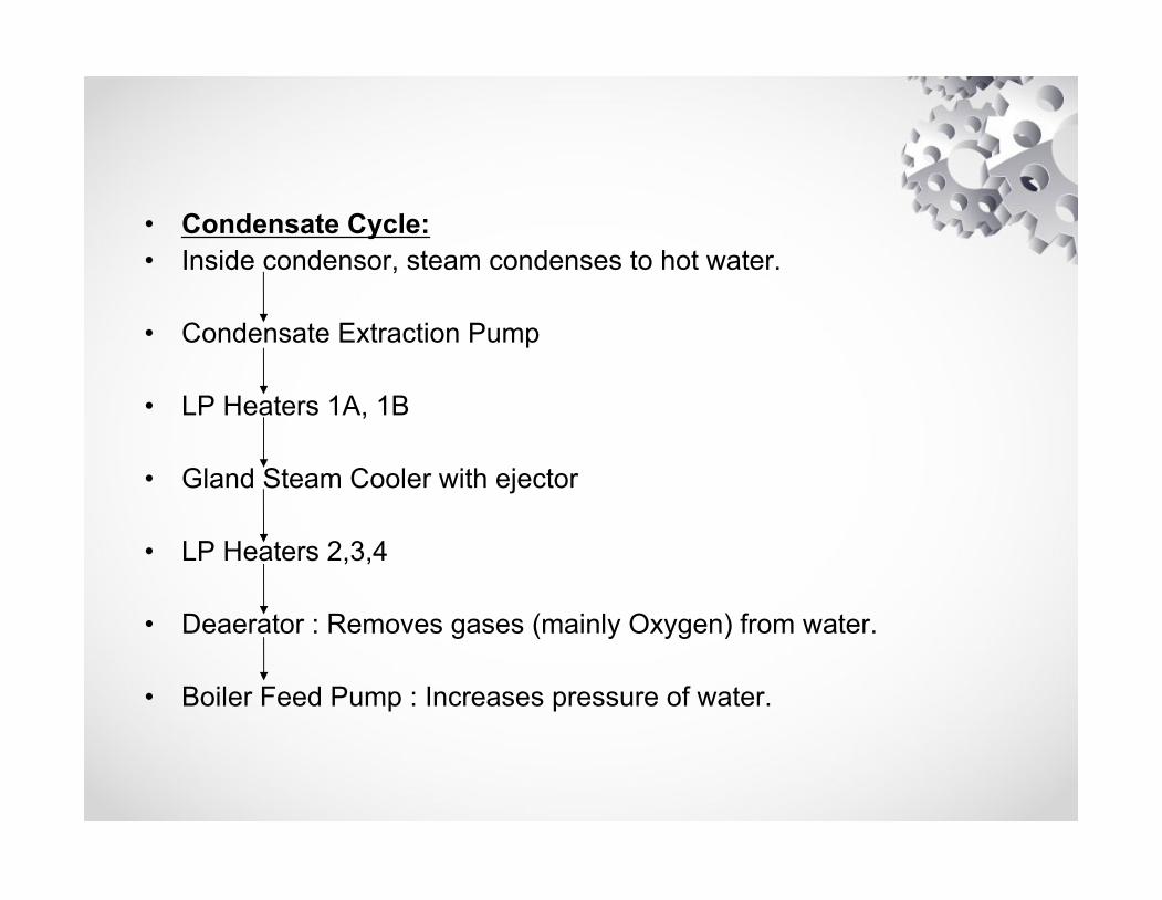
• Condensate Cycle:• Inside condensor, steam condenses to hot water.
• Condensate Extraction Pump
• LP Heaters 1A, 1B
• Gland Steam Cooler with ejector
• LP Heaters 2,3,4
• Deaerator : Removes gases (mainly Oxygen) from water.
• Boiler Feed Pump : Increases pressure of water.

• Feed Water Cycle:• Boiler Feed Pump
• HP Heaters 5,6,7
• Economiser
• Boiler drum : through furnace via tubes
• Once again, the steam cycle takes place.• Feed water is called so because as we see, condensed steam in
condenser is once again fed to turbine via furnace.• Therefore, steam cycle, condensate cycle, feed water cycle
constitute a closed loop cycle.

• Flue gas cycle:• Flue gases are formed in the funace, as a result of combustion.
• Platen Superheater
• Re heater
• Final and low temperature super heaters
• Economiser
• Air pre heater
• ESP : Removes ash present in Flue gases
• ID Fan
• Chimney
CONTROL AND INSTRUMENTATION DEPARTMENT• Responsible for control of various process parameters:
– Pressure– Temperature– Flow– Displacement– Conductance

MEASUREMENT TECHNIQUES
• TEMPERATURE:• THERMOCOUPLE:• Consists of two dissimilar
conductors that contact each other at one or more spots. It produces a voltage when the temperature of one of the spots differs from the reference temperature at other parts of the circuit.
• Types of thermocoules:– Type J– Type K– Type E– Type T– Type N– Type S – Type R– Type B

• RESISTANCE TEMPERATURE DETECTOR (RTD):
• Based on the principle that a material's resistance changes with temperature.
• Main trend for industrial resistance temperature detector is platinum RTD due to physical stability and high applicable temperature.
• There are the other RTDs such as Nickel, Platinum-cobalt, and so on.

• Types of RTDs:– Based on wiring configurations:
• TWO WIRE• THREE WIRE• FOUR WIRE
– Standard platinum Resistance Thermometers (SPRTs): Has highest accuracy
– Secondary Standard platinum Resistance Thermometers (Secondary SPRTs)
– Industrial PRTs : are designed to withstand industrial environments

• THERMOCOUPLES VS RTDs:• Thermocouple vs. RTD:• Temperature range:• First, consider the difference in temperature ranges. Noble Metal Thermocouples can reach 3,100 F, while
standard RTDs have a limit of 600 F and extended range RTDs have a limit of 1,100 F.
• Cost:• A plain stem thermocouple is 2 to 3 times less expensive than a plain stem RTD. A thermocouple head
assembly is roughly 50% less expensive than an equivalent RTD head assembly. • Accuracy, Linearity, & Stability:• As a general rule, RTDs are more accurate than thermocouples. This is especially true at lower
temperature ranges. RTDs are also more stable and have better linearity than thermocouples. If accuracy, linearity, and stability are your primary concerns and your application is within an RTD’s temperature limits, go with the RTD.
• Durability:• In the sensors industry, RTDs are widely regarded as a less durable sensor when compared to
thermocouples. • Response Time:• RTDs cannot be grounded. For this reason, they have a slower response time than grounded
thermocouples. Also, thermocouples can be placed inside a smaller diameter sheath than RTDs. A smaller sheath diameter will increase response time. For example, a grounded thermocouple inside a 1/16” dia. sheath will have a faster response time than a RTD inside a ¼” dia. sheath.

• Pressure Measurement:• Pressure measurement at NTPC
Badarpur is done mainly using pressure sensors. Pressure sensors are basically transducers: they generate an output voltage as a function of an input pressure.
• Types of pressure maesurements:– Head pressure:Head pressure(or
pressure head) measures the static pressure of a liquid in a tank or a pipe. Head pressure, P, is a function solely on the height of the liquid, h, and weight density, w, of the liquid being measured

• Absolute pressure measurement is measured relative to a vacuum
• Gauge pressure is measured relative to ambient atmospheric pressure
• Differential pressure is similar to gauge pressure, but instead of measuring relative to ambient atmospheric pressure, differential measurements are taken with respect to a specific reference pressure

• At NTPC Badarpur, the force collector type of sensor is used, where a diaphragm measures the applied force per unit area.
• Many other kinds of pressure sensors.– Wheatstone bridge (strain based) sensors :are the most common– A variable capacitance pressure transducer: measures the change in
capacitance between a metal diaphragm and a fixed metal plate. (Capacitance changes with change in distance between plates)
– Piezoelectric pressure transducer take advantage of the electrical properties of naturally occurring crystals such as quartz. These crystals generate an electrical charge when they are strained.
The natural output of a pressure transducer is a voltage.Many pressure transducers will output a conditioned 0-5V signal or 4-20 mA current.
The 0-5V and 4-20 mA signals can easily be measured by Data Acquisition (DAQ) hardware.

• FLOW MEASUREMENT:• A flow sensor is a device for sensing the rate of fluid flow. Typically
a flow sensor is the sensing element used in a flow meter, or flow logger, to record the flow of fluids
• the flow rate is determined inferentially by measuring the liquid's velocity or the change in kinetic energy. Velocity depends on the pressure differential that is forcing the liquid through a pipe or conduit.
• The use of differential pressure as an inferred measurement of a liquid's rate of flow is well known.
• This method exploits Bernoulli's theorem.– P0 + hpg + (1/2)pv2 = constant , P0 = PRESSURE, p=DENSITY
OF FLUID

CONTROL OF VARIOUS PROCESSES
• Transmitters : Produce an output current of 4-20 mA, using 24V DC input.
• 71E Card: Detects if current through transmitter less than 4 mA.
• 19E Card: Converts 4-20 mA current to 1-5 V voltage.
• 76R Card: setter card: Helps us set required voltage.
• 74R Card: error between measured, set value determined using PID controller.
• Auto Manual Logic Card: connected to 4 switches: Manual, Auto, Raise, Lower
• In auto mode, pins 6,26 of AML card connect to pins 7,27 respectively

• Pulse Collector Card: Collects any fasle pulses (basically noise).
• POS Cards: Switches which activate contactors.

HOW CIRCUITS ARE CONTROLLED/ACTIVATED??
• Relays:• Relays are simple switches which
are operated both electrically and mechanically. Relays consist of a n electromagnet and also a set of contacts. The switching mechanism is carried out with the help of the electromagnet
• Iron core is surrounded by a control coil. As shown, the power source is given to the electromagnet through a control switch and through contacts to the load. When current starts flowing through the control coil, the electromagnet starts energizing and thus intensifies the magnetic field. Thus the upper contact arm starts to be attracted to the lower fixed arm and thus closes the contacts causing a short circuit for the power to the load.

• TYPES OF RELAYS:
• Normally Open Contact (NO) – NO contact is also called a make contact. It closes the circuit when the relay is activated. It disconnects the circuit when the relay is inactive.
• Normally Closed Contact (NC) – NC contact is also known as break contact. This is opposite to the NO contact. When the relay is activated, the circuit disconnects. When the relay is deactivated, the circuit connects.

• As soon as the coil current is off, the movable armature will be returned by a force back to its initial position.
• Shown left is a simple relay.• When current is applied to coil,
it is magnetized, and the switch closes.
• As soon as the current flow stops through pins 1 and 3, the switch opens and thus the open circuit prevents the current flow through pins 2 and 4. Thus the relay becomes de-energized and thus in off position.

TURBINE SUPERVISORY INSTRUMENTATION• Monitors. under all operating conditions, a multitude of turbine
generator operating parameters. These parameters are:• Turbine generator bearing vibrations.• HP and LP turbine axial differential expansions.• Rotor Eccentricity• Shaft axial position.
• . Information provided by the system is used by the control room operator to verify that the turbine generator is operating within the safe limits. And, if this is not the case, the operator should takeappropriate actions to protect the machine from abnormal conditions that could result in damage.


!['llf crc=cn - NRPC · Request Detail 1 NTPC [ DELHI ] Anta(NTPC)-Swaimadhopur ... NTPC [ DELHI ] Anta(NTPC)-Lalsot(RVPNL) 2(220 kV) Powergrid Continuous. Annual Bay …](https://static.documents.pub/doc/80x56/5acd10827f8b9a93268d2ca5/llf-crccn-detail-1-ntpc-delhi-antantpc-swaimadhopur-ntpc-delhi-.jpg)


