The given paper represents an attempt to generalize some practical principles of modeling ship surfaces with the use of NURBS. NURBS-based representation of curves and surfaces has already become a standard of computermodeling for many industries. Since 2000 the leading producers of CAD systems for shipbuilding also use this standard for a ship surface definition. NURBS-based representation gives such wide opportunities for modeling as no other means do es and, at the same time, NURBS has a series of features creating difficulties for understanding by the user. It is a mechanism which controls the shape of curves and surfaces that a user faces at first modeling with the NURBS. Traditionally, in all previously existing lofts methods, control of the shape of curves and surfaces was carried out by defining points through which there passed a required curve or a surface. In a case with NURBS the curve passes only through finite points of a reference polygon. The shape of a curve will be defined by the shape of the reference polygon but to make a curve or a surface pass through the given point auxiliary conditions are required. During a long time the basic method of modeling a ship surface was a method of defining a grid oflines on this surface. Various mathematical models were used as the mathematical representation of curves. The most widespread model was a spline, which is analogous to a flexible spiling batten. It was a grid ofintersecting lines that determined a ship surface. Frames, waterlines and buttocks, generally, were used as the lines. If during the operation with the surface there arose a necessity of deriving coordinates of whateverpoint of the surface, the algorithm for calculation of the given point was started depending on the shape ofadjacent lines. Advantages of the given method include operation of the user with lines which are natural fora ship constructor. Disadvantage of this method is the absence of an analytically continuous (on tangents and curvature) surface. Notwithstanding the fact that NURBS-based representation of a ship surface meets the requirements of analyticity and smoothness, the absence of possibility of controlling the shape of the surface by means of direct modification of frames, waterlines and buttocks may become a major problem for a novice user. Besides, as a rule, a NURBS surface is visualized as a set of lines of equal parameterwhich hardly explain the shape of the given surface to the user. Therefore, many NURBS modellers include a method of shaping a surface which passes through a set of cross sections (Cross sectional design). Unfortunately, this method is not always applicable in case of a ship surface since it is impossible to describe intricate contours, as for example, a bow bulb. One of solutions of this problem can be the possibility to dynamically map the deformation of sections while editing co ntrol points of the surface. The user will control the shape of the surface by moving the control points of a polyhedron and thus the user can watch interactive deformation of sections. As distinct from aviation or automotive industry where the shape of the hull is developed and optimized during a long time, the terms of developing a surface in shipbuilding are very tight and in this case the optimum division of the surface into patches becomes of high importance for construction of a NURBS-based ship surface. While dividing the surface into patches, it is necessary to take into account a series of mathematical features of curves and surfaces. Based on a long-term experience of the NURBS- based simulation of ship surfaces it is po ssible to offer the following principal req uirements for dividing a surface into patches: - Usage of degree of NURBS surfaces is not higher than the third degree. The higher degree gives an additional smoothness of a surface and at the same time augments a range of variation of the surface at correction of one control point. Thus, the property of localization of the surface modification is lost and there occurs a necessity of increasing the amount of control points. - Obligatory segmentation into separate patches of the surface between knuckle lines. Usage ofmathematical NURBS properties for creation of knuckles inside the surface patch is possible, but labor- intensive for control and is practically not supp orted by many systems if it is necessary to transmit data from one system to another. - Obligatory segmentation of flat side p atches, flat bottom patches and pa tches of ruled surfaces allows to effectively controlling the shape of these lines. Without segmentation into separate patches of the surface it is practically impossible to obtain a correct line of a flat side or bottom only by means of control points ofthe surface. - Attributable to NURBS limitation of the amount of boundary lines of the surface patches (usually
The given paper represents an attempt to generalize some practica principles of modeling ship surfaces with the use of NURBS.
NURBS-based representation of curves and surfaces has already become a standard of compute
modeling for many industries. Since 2000 the leading producers of CAD systems for shipbuilding also use
this standard for a ship surface definition. NURBS-based representation gives such wide opportunities for modeling as no other means does and
at the same time, NURBS has a series of features creating difficulties for understanding by the user.
It is a mechanism which controls the shape of curves and surfaces that a user faces at first modelingwith the NURBS. Traditionally, in all previously existing lofts methods, control of the shape of curves and
surfaces was carried out by defining points through which there passed a required curve or a surface. In a
case with NURBS the curve passes only through finite points of a reference polygon. The shape of a curvwill be defined by the shape of the reference polygon but to make a curve or a surface pass through the
given point auxiliary conditions are required.
During a long time the basic method of modeling a ship surface was a method of defining a grid of
lines on this surface. Various mathematical models were used as the mathematical representation of curvesThe most widespread model was a spline, which is analogous to a flexible spiling batten. It was a grid o
intersecting lines that determined a ship surface. Frames, waterlines and buttocks, generally, were used a
the lines. If during the operation with the surface there arose a necessity of deriving coordinates of whatever point of the surface, the algorithm for calculation of the given point was started depending on the shape o
adjacent lines. Advantages of the given method include operation of the user with lines which are natural fo
a ship constructor. Disadvantage of this method is the absence of an analytically continuous (on tangentand curvature) surface. Notwithstanding the fact that NURBS-based representation of a ship surface meet
the requirements of analyticity and smoothness, the absence of possibility of controlling the shape of the
surface by means of direct modification of frames, waterlines and buttocks may become a major problem
for a novice user. Besides, as a rule, a NURBS surface is visualized as a set of lines of equal parametewhich hardly explain the shape of the given surface to the user. Therefore, many NURBS modellers include
a method of shaping a surface which passes through a set of cross sections (Cross sectional design)
Unfortunately, this method is not always applicable in case of a ship surface since it is impossible todescribe intricate contours, as for example, a bow bulb. One of solutions of this problem can be the
possibility to dynamically map the deformation of sections while editing control points of the surface. The
user will control the shape of the surface by moving the control points of a polyhedron and thus the user canwatch interactive deformation of sections.
As distinct from aviation or automotive industry where the shape of the hull is developed and
optimized during a long time, the terms of developing a surface in shipbuilding are very tight and in thiscase the optimum division of the surface into patches becomes of high importance for construction of a
NURBS-based ship surface. While dividing the surface into patches, it is necessary to take into account
series of mathematical features of curves and surfaces. Based on a long-term experience of the NURBS
based simulation of ship surfaces it is possible to offer the following principal requirements for dividing surface into patches:
- Usage of degree of NURBS surfaces is not higher than the third degree. The higher degree gives an
additional smoothness of a surface and at the same time augments a range of variation of the surface a
correction of one control point. Thus, the property of localization of the surface modification is lost andthere occurs a necessity of increasing the amount of control points.
- Obligatory segmentation into separate patches of the surface between knuckle lines. Usage omathematical NURBS properties for creation of knuckles inside the surface patch is possible, but labor
intensive for control and is practically not supported by many systems if it is necessary to transmit data from
one system to another.- Obligatory segmentation of flat side patches, flat bottom patches and patches of ruled surfaces allow
to effectively controlling the shape of these lines. Without segmentation into separate patches of the surface
it is practically impossible to obtain a correct line of a flat side or bottom only by means of control points of
the surface.- Attributable to NURBS limitation of the amount of boundary lines of the surface patches (usually
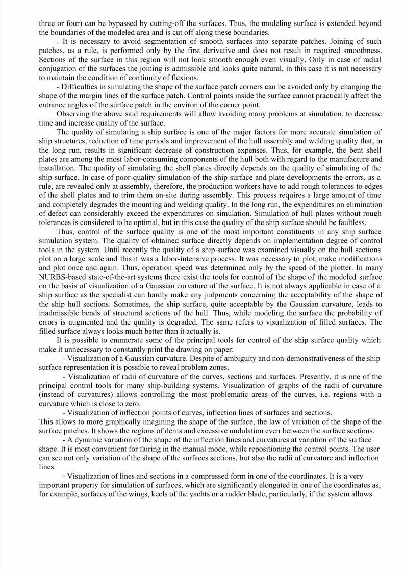
three or four) can be bypassed by cutting-off the surfaces. Thus, the modeling surface is extended beyondthe boundaries of the modeled area and is cut off along these boundaries.
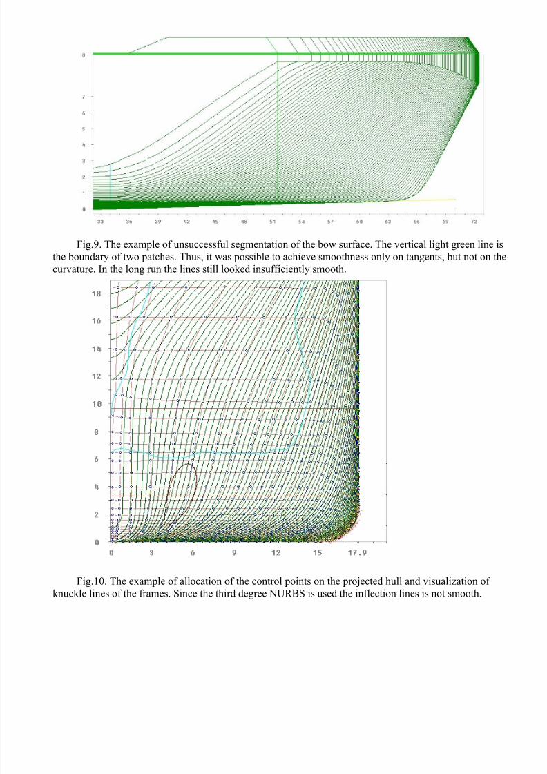
- It is necessary to avoid segmentation of smooth surfaces into separate patches. Joining of such patches, as a rule, is performed only by the first derivative and does not result in required smoothness
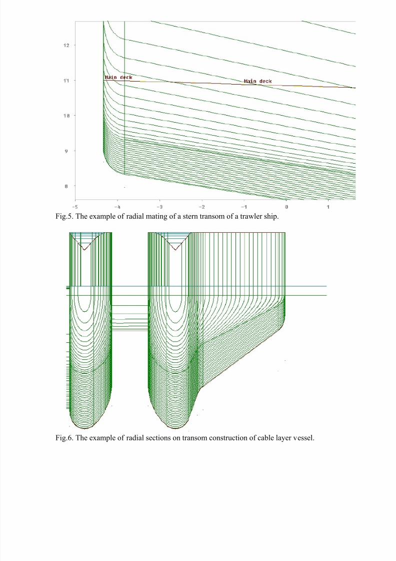
Sections of the surface in this region will not look smooth enough even visually. Only in case of radia
conjugation of the surfaces the joining is admissible and looks quite natural, in this case it is not necessaryto maintain the condition of continuity of flexions.
- Difficulties in simulating the shape of the surface patch corners can be avoided only by changing the
shape of the margin lines of the surface patch. Control points inside the surface cannot practically affect theentrance angles of the surface patch in the environ of the corner point.
Observing the above said requirements will allow avoiding many problems at simulation, to decrease
time and increase quality of the surface.The quality of simulating a ship surface is one of the major factors for more accurate simulation o
ship structures, reduction of time periods and improvement of the hull assembly and welding quality that, in
the long run, results in significant decrease of construction expenses. Thus, for example, the bent shel
plates are among the most labor-consuming components of the hull both with regard to the manufacture andinstallation. The quality of simulating the shell plates directly depends on the quality of simulating of the
ship surface. In case of poor-quality simulation of the ship surface and plate developments the errors, as a
rule, are revealed only at assembly, therefore, the production workers have to add rough tolerances to edgeof the shell plates and to trim them on-site during assembly. This process requires a large amount of time
and completely degrades the mounting and welding quality. In the long run, the expenditures on elimination
of defect can considerably exceed the expenditures on simulation. Simulation of hull plates without roughtolerances is considered to be optimal, but in this case the quality of the ship surface should be faultless.
Thus, control of the surface quality is one of the most important constituents in any ship surface
simulation system. The quality of obtained surface directly depends on implementation degree of contro
tools in the system. Until recently the quality of a ship surface was examined visually on the hull sections plot on a large scale and this it was a labor-intensive process. It was necessary to plot, make modification
and plot once and again. Thus, operation speed was determined only by the speed of the plotter. In many
NURBS-based state-of-the-art systems there exist the tools for control of the shape of the modeled surfacon the basis of visualization of a Gaussian curvature of the surface. It is not always applicable in case of a
ship surface as the specialist can hardly make any judgments concerning the acceptability of the shape o
the ship hull sections. Sometimes, the ship surface, quite acceptable by the Gaussian curvature, leads toinadmissible bends of structural sections of the hull. Thus, while modeling the surface the probability o
errors is augmented and the quality is degraded. The same refers to visualization of filled surfaces. Th
filled surface always looks much better than it actually is.It is possible to enumerate some of the principal tools for control of the ship surface quality which
make it unnecessary to constantly print the drawing on paper:
- Visualization of a Gaussian curvature. Despite of ambiguity and non-demonstrativeness of the ship
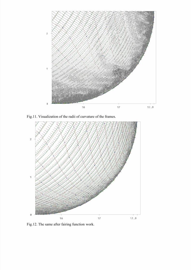
surface representation it is possible to reveal problem zones.- Visualization of radii of curvature of the curves, sections and surfaces. Presently, it is one of the
principal control tools for many ship-building systems. Visualization of graphs of the radii of curvatur
(instead of curvatures) allows controlling the most problematic areas of the curves, i.e. regions with a
curvature which is close to zero.- Visualization of inflection points of curves, inflection lines of surfaces and sections.
This allows to more graphically imagining the shape of the surface, the law of variation of the shape of thesurface patches. It shows the regions of dents and excessive undulation even between the surface sections.
- A dynamic variation of the shape of the inflection lines and curvatures at variation of the surface
shape. It is most convenient for fairing in the manual mode, while repositioning the control points. The usercan see not only variation of the shape of the surfaces sections, but also the radii of curvature and inflection
lines.
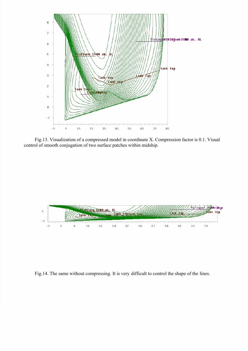
- Visualization of lines and sections in a compressed form in one of the coordinates. It is a very
important property for simulation of surfaces, which are significantly elongated in one of the coordinates asfor example, surfaces of the wings, keels of the yachts or a rudder blade, particularly, if the system allows
editing control points of the surface in this mode. It is also a very useful property for control of butting thelines of the sections to a flat side, flat bottom, as well as for control of joining the bow and stern patchs of
surfaces in the midship. Compressing a model in one of the coordinates is similar to visual inspection of theshape of the curves in the drawing if viewed along the curve and, thus, the viewer eye level is hardly above
the level of the table. If in the compressed form the model looks smooth, it will look even better in the
normal form.- An automatic control of deviations from the source data. In some cases when it is necessary to
achieve a high degree of approximation of the modeled surface to the initial one, a constant control of
deviations from the initial points is required. It is especially important if it is necessary to restore the surfaceof an existing ship for reconditioning or remodeling. In such cases the criterion of the surface quality is
minimization of deviations from the source data.
Application of the surface quality control tools mentioned above allows to completely abandoning printing the drawings on paper, to greatly reduce the time of simulation and considerably increase th
quality of a modeled surface.
The rules and requirements described in this paper are founded on a long-term experience of using the
Sea Solution system. In view of similarity of the mathematical representation of curves and surfaces this isapplicable for most of other NURBS-based systems.
Summarizing the aforesaid it is possible to distinguish some the principal stages of designing a ship
surface:- The analysis of the shape of a modeled surface and selection of segmentation into patches. It is a
very important factor while creating a surface. The labor intensity of simulation and quality of a surface
depends on optimality of segmentation of the surface into patches.- The definition of the surface patches with a minimum set of control points, approximation of the
shape of a surface to the source data and allocation of the control points. Your idea of the shape of a surface
if the hull is designed “from scratch” or the lines of an initial body lines drawing, or the offset table point
can be taken as the source data.- increase in amount of the control points, definition of inflection lines on frames, waterlines and
buttocks, more exact approximation to the source data. At this stage it is necessary to make efforts fo
minimizing the deviation from the source data and at the same time defining correct arrangement of theinflection lines, i.e. eliminating errors, which exist in the initial source data.
- Minimization of the curvature of waterlines, frames and buttocks. At this final stage it is necessary to
achieve the acceptable smoothness of lines of the sections. It is a repetitive process and, generally, a smaldisplacement of control points is enough for meeting the smoothness requirements. During the smoothing
process it is also necessary to control position of inflection lines.
Following this technique and using the Sea Solution system during the last five years only the“Steelcad Consultants AS” company has simulated more than 200 surfaces of the hulls of different types o
the vessels. The most of them were used at construction of the vessels and have proved to be the high
quality surfaces and shell plate developments. This paper is only a small part of accumulated practica
experience, but it also can be useful both for novice users and specialists in simulating with the use o NURBS.
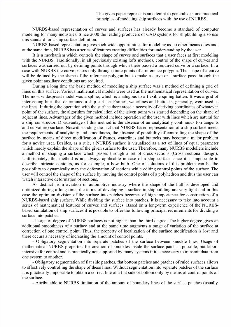
Fig.1. The example of segmentation of a fore body of a supply vessel into surface patches. The basic surfaceis carried out for one patch and formed by a line of a flat bottom, a line of bilge radius, a line of a flat side
transforming into a deck-line and a line of a buttock in CL (blue lines). In the area of the upper deck th
surface is elongated beyond the knuckle line of the side and is cut off by a vertical surface of the bulwark (ared line).
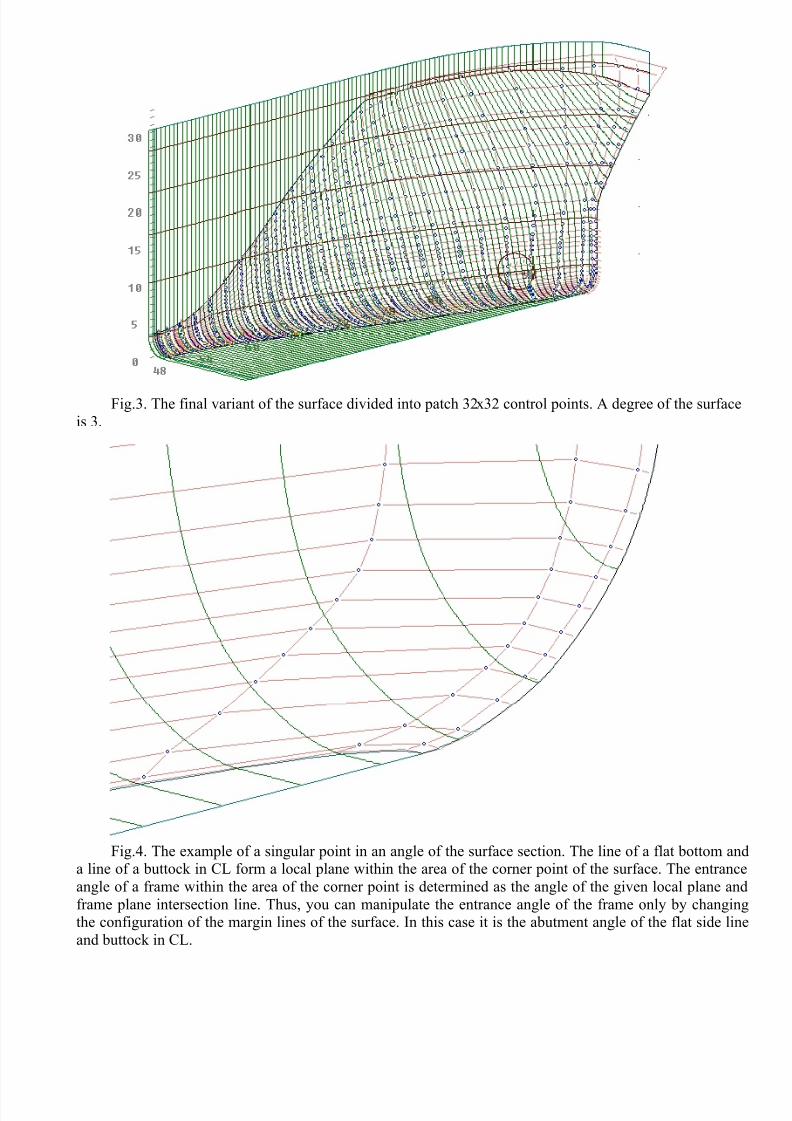
Fig.3. The final variant of the surface divided into patch 32х32 control points. A degree of the surface
is 3.
Fig.4. The example of a singular point in an angle of the surface section. The line of a flat bottom anda line of a buttock in CL form a local plane within the area of the corner point of the surface. The entrance
angle of a frame within the area of the corner point is determined as the angle of the given local plane and
frame plane intersection line. Thus, you can manipulate the entrance angle of the frame only by changingthe configuration of the margin lines of the surface. In this case it is the abutment angle of the flat side lin
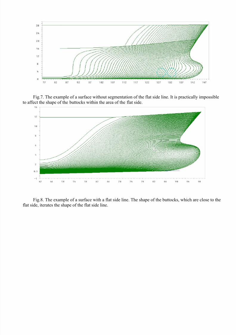
Fig.7. The example of a surface without segmentation of the flat side line. It is practically impossible
to affect the shape of the buttocks within the area of the flat side.
Fig.8. The example of a surface with a flat side line. The shape of the buttocks, which are close to theflat side, iterates the shape of the flat side line.