On Interference Microscopy Author(s): Thomas Merton Source: Proceedings of the Royal Society of London. Series A, Mathematical and Physical Sciences, Vol. 191, No. 1024 (Sep. 26, 1947), pp. 1-6 Published by: The Royal Society Stable URL: http://www.jstor.org/stable/98153 . Accessed: 05/05/2014 00:23 Your use of the JSTOR archive indicates your acceptance of the Terms & Conditions of Use, available at . http://www.jstor.org/page/info/about/policies/terms.jsp . JSTOR is a not-for-profit service that helps scholars, researchers, and students discover, use, and build upon a wide range of content in a trusted digital archive. We use information technology and tools to increase productivity and facilitate new forms of scholarship. For more information about JSTOR, please contact [email protected]. . The Royal Society is collaborating with JSTOR to digitize, preserve and extend access to Proceedings of the Royal Society of London. Series A, Mathematical and Physical Sciences. http://www.jstor.org This content downloaded from 195.78.108.54 on Mon, 5 May 2014 00:23:26 AM All use subject to JSTOR Terms and Conditions
Transcript
On Interference MicroscopyAuthor(s): Thomas MertonSource: Proceedings of the Royal Society of London. Series A, Mathematical and PhysicalSciences, Vol. 191, No. 1024 (Sep. 26, 1947), pp. 1-6Published by: The Royal SocietyStable URL: http://www.jstor.org/stable/98153 .
Accessed: 05/05/2014 00:23
Your use of the JSTOR archive indicates your acceptance of the Terms & Conditions of Use, available at .http://www.jstor.org/page/info/about/policies/terms.jsp
.JSTOR is a not-for-profit service that helps scholars, researchers, and students discover, use, and build upon a wide range ofcontent in a trusted digital archive. We use information technology and tools to increase productivity and facilitate new formsof scholarship. For more information about JSTOR, please contact [email protected].
.
The Royal Society is collaborating with JSTOR to digitize, preserve and extend access to Proceedings of theRoyal Society of London. Series A, Mathematical and Physical Sciences.
http://www.jstor.org
This content downloaded from 195.78.108.54 on Mon, 5 May 2014 00:23:26 AMAll use subject to JSTOR Terms and Conditions
Interference microscopy provides a method of increasing the visibility of specimens which are colourless and which differ slightly in refractive index from the surrounding medium by enclosing them between semi-reflecting surfaces, which thus constitute an interferometer. In making observations by this method, it is necessary to use monochromatic light or light of two different wave-lengths, which can be isolated conveniently by the use of a mercury-arc lamp with appropriate filters. This method owes its inception to Frederikse (I 93 3), and has been further developed by the writer in a recent communication (Merton, 1947).
When monochromatic light falls normally on a pair of semi-reflecting surfaces which are parallel to one another, the intensity of the light which is transmitted is a function of the separation of the plates and, owing to the effect of multiple reflexions, a curve in which intensity is plotted against separation shows a succession of maxima the width of which, in relation to the minima between them, depends on the reflecting power of the semi-reflecting surfaces. The introduction of a body of different refrac- tive index between the plates is optically equivalent to changing their separation with the result that if the plates are at a distance such that the transmission is a maximum, a small change in refractive index is sufficient to cause a great decrease in the transmission. In such a case the body would be seen as a dark object on a bright background. For other separations of the plates the reverse may occur and the body may be seen bright on a dark background. When two radiations (e.g. the green and violet lines of mercury) are used simultaneously it frequently occurs that the object appears in one colour and the background in another,
In the communication referred to (Merton 1947), I have described a technique of
making observations by this method and of preparing semi-reflecting surfaces which are well adapted to the purpose. It was found possible to observe intricate detail in certain thin cells, and living bacteria could be clearly seen under a high magni- fication, but these results could only be obtained in the case of specimens a few microns in thickness.
The reason for this limitation lies in the following considerations. The optical difference of path between successively reflected rays depends not only on the separa- tion of the plates and the refractive index of the medium between them, but also varies directly as the cosine of the angle which the rays make with the normal. Thus for any separation of the plates (other than a very small separation) there will be a number of maxima and minima at different angles of incidence, the maxima being at those angles of incidence at which the optical difference of path is equal to an integral number of wave-lengths of the light used is making the observations. If the
Vol. i9I. A. (26 September I947) [ 1 ] I
This content downloaded from 195.78.108.54 on Mon, 5 May 2014 00:23:26 AMAll use subject to JSTOR Terms and Conditions
light has passed through the half-metallized plates in a convergent cone subtending a substantial angle it is evident that unless the separation of the plates is very small the total amount of light transmitted will not vary appreciably with the separation of the plates, the only effect of a change in the separation being that those rays which reach the observer will have passed through the plates at a different series of angles; and the introduction of an object of different refractive index will not give rise to any substantial change in intensity. Unless the specimen is very thin it is necessary to illuminate it with parallel or nearly parallel light. This however would result in an intolerable reduction in the resolving power of the microscope and also a reduction in the intensity of the light which would be so great as to render observation at high magnifications impracticable.
I have obtained good results with specimens up to a few microns in thickness by a compromise which consisted in putting a piece of ground glass on the microscope stage with the ground surface uppermost and with the half-platinized slide and its cover on the ground glass. The image of the mercury lamp after traversing the filter and after reflexion from the mirror of the microscope was brought to a focus on the ground glass by means of a lens of 15 in. focus working atf/3.1, the objective being thus illuminated in a manner determined by the polar curve of the ground glass, the greatest intensity being along the optic axis.
It is easy to see exactly what happens by the following procedure. The mercury lamp was brought to a focus on a platinized slide with a platinized cover, which was not quite flat, by means of a condenser of 1 in. focus working atf/l125 (N.A. =037). The eyepiece of the microscope was removed and replaced by a viewer which con- sisted of a convex lens of about 1O in. focus in a brass cell with a very small hole through which the rear lens of the objective could be seen. Under these conditions, the rear lens is seen illuminated by a series of concentric rings (resembling Fabry and Perot rings seen at infinity). When the stage of the microscope is slightly moved, the rings contract or expand as the case may be since the plates are not quite parallel, but the total amount of light which reaches the eye is substantially the same unless the rings are very few in number. The result is that when the viewer is replaced by the eyepiece, no fringes can be seen. What is wanted is an angular filter which will limit transmission to one set of rings only and, if such a filter were available, then on changing the separation of the plates, the rings would assume a new series of angles which the angular filter would reject and the fringes would be visible through the eyepiece.
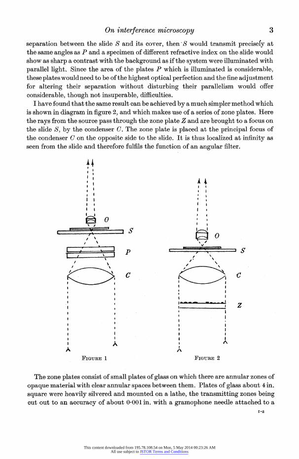
This suggests the use of two pairs of semi-reflecting plates in series, a device which has been used in other fields for many years. An arrangement which is attractive on theoretical grounds is shown (figure 1). Here the rays from the lamp after tra- versing the condenser C converge through a pair of plane parallel semi-reflecting plates P and after being brought to a focus on the semi-reflecting slide and cover S, diverge to the objective 0. The plates P would need to be provided with a fine adjustment for altering their separation. Their function would be simply that of an angular filter and if they were set so as to be a,t the same optical separation as the
This content downloaded from 195.78.108.54 on Mon, 5 May 2014 00:23:26 AMAll use subject to JSTOR Terms and Conditions
separation between the slide S and its cover, then S would transmit precisefy at the same angles as P and a specimen of different refractive index on the slide would show as sharp a contrast with the background as if the system were illuminated with parallel light. Since the area of the plates P which is illuminated is considerable, these plates wouldneed to be of the highest optical perfection and the fine adjustment for altering their separation without disturbing their parallelism would offer considerable, though not insuperable, difficulties.
I have found that the same result can be achieved by a much simpler method which is shown in diagram in figure 2, and which makes use of a series of zone plates. Here the rays from the source pass through the zone plate Z and are brought to a focus on the slide S, by the condenser C. The zone plate is placed at the principal focus of the condenser C on the opposite side to the slide. It is thus localized at infinity as seen from the slide and therefore fulfils the function of an angular filter.
C '
l l As~~~
Fiu, I FiGm2
opaqu& material I withceranlrsae ewe hm ltso lsbu 4 in
I I
ou ot o nacurcyofa ot I0 I 'i.wt Irmpoe edeatce o-
~~~~~~~~~~~~~~~~~~~~~~~-2
I C 1 l 9 I I A
, ' |~ FI uR 1 FIR 2
The zon pltscoss f ml lae f ls n hc heeae nuaznso opaque~~~~~ maera wIt cla anua.pcsbtente. P,lae of glsZbu n sqar wer hevl sivrdadmutdol ah,tetasitn oeen cu ou to anacrc!faotOOli.wt rmpoenel tahdt
. .~~~~~~~~~~~~~~~~~-
This content downloaded from 195.78.108.54 on Mon, 5 May 2014 00:23:26 AMAll use subject to JSTOR Terms and Conditions
hacksaw blade as a tool. If the order of interference at the centre of a system is N, n the number of a ring reckoned from the centre, f the focal length of the condensing lens, 0 the angle subtended by the nth ring and r the radius of the corresponding circle on the zone plate, we have 1 - n/N = cos 0 and r = F tan 0, from which the radii of the zones can be calculated. For a high degree of purity it is necessary that the transmitting zones should be narrow. Good results have been obtained by working out a series of values of r for n = 0-2, 10, 1*2, 2'0, 22, etc., and cutting out the silver in the regions corresponding to 0.0 to 0-2, 1P0 to 1-2, etc. The zone plates used in observations were prepared from the silvered glass zone plates by photo- graphy on very fine grained photographic plates with the required reduction in scale and slips of glass were cemented on to the photographic zone plates to ensure their permanence. It is found that a plate which has been calculated for a given order of interference is in fact reasonably effective over a number of orders on either side, so that the total number of zone plates which are required is not excessive.
On looking through the viewer it is not difficult to choose a zone plate which matches the rings seen on the rear lens of the objective but the centring of the zone plate calls for a precision which can hardly be effected without some form of mechani- cal fine adjustment and which increases in difficulty with the number of zones used. I have made zone plates with which clearly defined fringes have been observed up to an order of 140 in mercury green light, which corresponds to a separation of the plates of about 38,t with air and about 29a when water is used between the plates. There seems no reason why this limit should not be exceeded.
The zone plates which have been described above are designed for specified orders of interference and it is evident that if the microscope is illuminated by two radiations, a zone plate can only function effectively for one of them. My son, Mr C. R. Merton, has succeeded in making zone plates which are effective for two radiations simultaneously, for example the green and violet rays of mercury, the wave-lengths of which happen to be very nearly in the ratio of 5 to 4. Thus, for example, the 60th order of the green ray will be nearly coincident with the 75th order of the violet ray, and the problem is to make a zone plate which will function as a 60th order plate for the green ray and a 75th order plate for the violet ray. Instead of printing the zone plates on fine grain photographic plates, a plate of glass was coated with bichromated gelatine and was exposed to light under the negative of a 60th order zone plate. The plate was developed in hot water, the parts which had not been exposed to light being dissolved, leaving zones of bare glass. The plate was then dyed in eosin which made the gelatine opavque to the green ray whilst transmitting the violet ray. In the same way a bichromated gelatine plate was exposed under the negative of a 75th order zone plate and after development in hot water was dyed in a mixture of auremine and malachite green which absorbs the violet ray and freely transmits the green ray. These two stained gelatine plates were cemented together in register, the result being a two colour zone plate which functioned effectively for bQth the green and violet rays. Fringes of great purity of colour have been obtained up to the 80th order for the green ray and the 100th
This content downloaded from 195.78.108.54 on Mon, 5 May 2014 00:23:26 AMAll use subject to JSTOR Terms and Conditions
for the violet ray by this method. The matching of the two components is of course affected by the dispersion of any liquid between the two half-metallized plates but not to a degree which impairs the usefulness of the method. In using a mercury lamp as a source of light it is desirable to include, in addition to the didymium filter, a gelatine filter lightly stained with methylene blue.
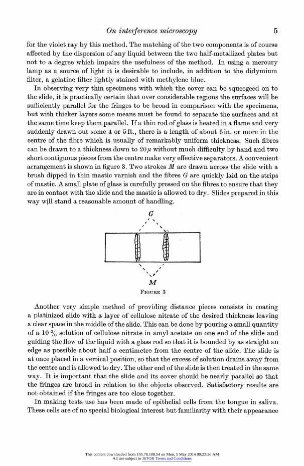
In observing very thin specimens with which the cover can be squeegeed on to the slide, it is practically certain that over considerable regions the surfaces will be sufficiently parallel for the fringes to be broad in comparison with the specimens, but with thicker layers some means must be found to separate the surfaces and at the same time keep them parallel. If a thin rod of glass is heated in a flame and very suddenly drawn out some 4 or 5 ft., there is a length of about 6 in. or more in the centre of the fibre which is usually of remarkably uniform thickness. Such fibres can be drawn to a thickness down to 20,u without much difficulty by hand and two short contiguous pieces from the centre make very effective separators. A convenient arrangement is shown in figure 3. Two strokes M are drawn across the slide with a brush dipped in thin mastic varnish and the fibres G are quickly laid on the strips of mastic. A small plate of glass is carefully pressed on the fibres to ensure that they are in contact with the slide and the mastic is allowed to dry. Slides prepared in this way will stand a reasonable amount of handling.
a
\ /
M FIGURE 3
Another very simple method of providing distance pieces consists in coating a platinized slide with a layer of cellulose nitrate of the desired thickness leaving a clear space in the middle of the slide. This can be done by pouring a small quantity of a 10 % solution of cellulose nitrate in amyl acetate on one end of the slide and guiding the flow of the liquid with a glass rod so that it is bounded by as straight an edge as possible about half a centimetre from the centre of the slide. The slide is at once placed in a vertical position, so that the excess of solution drains away from the centre and is allowed to dry. The other end of the slide is then treated in the same way. It is important that the slide and its cover should be nearly parallel so that the fringes are broad in relation to the objects observed. Satisfactory results are not obtained if the fringes are too close together.
In making tests use has been made of epithelial cells from the tongue in saliva. These cells are of no special biological interest but familiarity with their appearance
This content downloaded from 195.78.108.54 on Mon, 5 May 2014 00:23:26 AMAll use subject to JSTOR Terms and Conditions
made them convenient objects for testing the method. What is seen is in effect a contour map showing optical path differences and it is evident that this contour map must in some measure be distorted when the object is illuminated by oblique rays, unless the separation of the plates is very small. In the case of oblique illumina- tion successively reflected beams will pass through adjacent portions of the object or even outside the object. This effect is somewhat complicated and the extent of the resulting disturbance of the image is difficult to assess, but within certain limits it does not appear to be very important. With a condenser of numerical aperture 037 there does not appear to be any conspicuous difference in the structure of the cells when observed between plates with separations varying between 2 and 15
REFERENCES
Frederikse, A. M. I933 Acta brev. neerl. Physiol. 3, 8. Merton, T. I947 Proc. Roy. Soc. A, 189, 309.
Heat transfer at low temperatures between tube walls and gases in turbulent flow
BY T. A. HALL, Imperial College and Gas Research Board AND P. H. TSAO, Imperial College
(Communicated by Sir Alfred Egerton, Sec.R.S.-Received 4 December 1946)
An apparatus was designed on the, counter-flow system to study heat transfer between tube walls and gases at low temperatures in a region in which careful measurements had not previously been made.
Oxygen, nitrogen and carbon dioxide were used, covering a temperature range from + 45? to - 167? C, pressures up to 11 atm., and Reynolds numbers from 3000 to 60,000.
Results were correlated by the use of dimensionless groups and a general equation ob- tained, independent of the nature of the gas and applicable over the whole range of experi- ments. With Reynolds numbers evaluated at mean film temperatures, the coefficient in the equation was found to be 5 % lower than that obtained from measurements made at normal and high temperatures. This is regarded as justifying the extension of the ordinary equation to low-temperature regions.
Determinations on friction accompanying heat transfer with gases in turbulent flow at low temperatures showed that the effect of heat transfer on the friction factor was small.
NOMENCLATURE
C constant in Sutherland equation. D diameter of tube; equivalent diameter of annulus i.e. internal diameter of
outer tube minus external diameter of inner tube. F frictional force per lb. of fluid.
This content downloaded from 195.78.108.54 on Mon, 5 May 2014 00:23:26 AMAll use subject to JSTOR Terms and Conditions