DREHMO i - matic Electrical actuator with integral controls Complementary operating manual for drives with PROFIBUS interface Installation manual T.-Nr. 166781 Operating manual Version 1.14 Date: September, 25 th 2013 INFORMATION This installation manual has to be used in conjunction with the operating manual for actuators (from version 1.11)! This manual must be kept for future use.
Transcript
DREHMO i - matic Electrical actuator with integral controls Complementary operating manual for drives with PROFIBUS interface
Installation manual T.-Nr. 166781 Operating manual Version 1.14 Date: September, 25th 2013 INFORMATION This installation manual has to be used in conjunction with the operating manual for actuators (from version 1.11)! This manual must be kept for future use.
Page 2 of 28 DREHMO i-matic Profibus
Page intentionally left blank
Page 3 of 28 DREHMO i-matic Profibus
TABLE OF CONTENTS
1 STRUCTURE OF THE PROFIBUS-INTERFACE BOARD ................................................. 4
1.1 SETTING OF ADDRESS .............................................................................................................. 5
2 CYCLIC AND ACYCLIC DATA TRANSFER ........................................................................ 6
There are different kinds of PROFIBUS-interfaces available. The block-diagrams are shown in the following:
Picture 1: Single PROFIBUS interface, process inputs optional
Picture 2: Line redundant PROFIBUS interface, process inputs optional
Page 5 of 28 DREHMO i-matic Profibus
Picture 3: Slave redundant PROFIBUS interface, process inputs optional
1.1 Setting of address
The actuators are delivered by default with the address 126. To change the address, there are different possible ways to do it:
- menu guided using the local control station - with a computer using the local programming interface (IR or Bluetooth) - using the PROFIBUS service SetSlaveAdress
The address is stored in a non-volatile memory on the main board.
Page 6 of 28 DREHMO i-matic Profibus
2 Cyclic and acyclic data transfer
The interface board supports the cyclic DPV0 protocol and also extended acyclic services of the Profibus DPV1 and DPV2 protocols. Additional to the cyclic data (commands and indications) the acyclic service can be used to transmit general information like parameters, operating as well as diagnosis data or data of the electronic type plate.
The availability of the extended services is given by the device key of the actuator electronic. The required activation can later on be done by means of a device key update, if not already done with the delivery status. The activation of DPV1 or DPV2 can be verified on the actuator menu: Actual values/diagnosis -> Interface-> Profibus -> Bus profile (DPV2 includes DPV1, DPV1 includes DPV0). Adaption of the Profibus functionality regarding the feedback indications is possible
by means of some dedicated parameters on the actuator menu: Parameters -> DCS/PLC system -> Interface -> Profibus. Details are given in the actuator instruction manual.
2.1 Cyclic driver interface
The data of the cyclic service consists of different data models which are divided into two modules each. The two modules of a data model only differ in the data consistency listed in the GSD-file. Modules with even numbers are byte-consistent. Modules with odd numbers are consistent over the complete data length. For information of how to handle the consistency refer to the documentation of the automation system. The status of the position value is listed in the following table: Table 1: Coding of status – according to PA-profile quality sub-status limits description 27 26 25 24 23 22 21 20 0 0 bad 0 1 uncertain 1 0 good (not cascaded) 1 1 good (cascaded)
2.1.1 Cyclic driver interface of PP1 and PP2 modules:
Table 2: Process structure of modules PP1 and PP2, inputs (PAE) ⇒ status data (10 byte) Byte Bit Signal Significance 0 All Position value high-byte 0...1000ppt actual position value
automatically fitted to range between limit positions 1 All Position value low-byte
2 all Status position value Status as per PA profile (refer to table 1)
3 0 General fault signal 1 General fault signal 1 is active ⇒ operating manual
1 General fault signal 2 General fault signal 2 is active ⇒ operating manual 2 Phase failure One of the three phases is missing
3 Failure internal 24 V DC Electronic unit is not supplied from main power
4 Failure externally supplied 24 V DC Electronic is not supplied from external source
5 Torque in OPEN direction Max. torque in the OPEN direction exceeded
6 Torque in CLOSE direction Max. torque in the CLOSE direction exceeded
7 Drive in fail-safe Drive is in the fail-safe mode
Page 7 of 28 DREHMO i-matic Profibus
Byte Bit Signal Significance 4 0 Drive travels to OPEN (only statically) Travelling signal in direction OPEN
1 Drive travels to CLOSE (only statically) Travelling signal in direction CLOSE
2 Drive at end of travel position OPEN indication if position ≥ 100% 3 Drive in end of travel position CLOSE indication if position ≤ 0% 4 Drive at end of travel position OPEN +
torque indication if position ≥ 100% and torque exceeds tripping torque in OPEN direction
5 Drive in end of travel position CLOSE + torque
indication if position ≤ 0% and torque exceeds tripping torque in CLOSE direction
6 Motor too hot motor operation blocked due to excessive temperature
7 Drive remote-controlled actuator can be controlled by external commands
5 0 Drive locally controlled Display of the operating mode
1 Drive in local operation The drive is locally operated
2 Activation of discrete commands actuator can be operated by commands OPEN or CLOSE (AUTOMATIC = 0)
3 Drive in learn mode Display of the operating mode
4 always 0, reserved for future use
5 limit switch-off in OPEN by torque parameter setting of switch-off condition in OPEN
6 limit switch-off in CLOSE by torque parameter setting of switch-off condition in CLOSE
7 Start-up bridging in OPEN active parameter setting
6 0 Start-up bridging in CLOSE active parameter setting
1 Local_ind = /Remote Drive is not in mode remote
2 Emergency travel active status indication of ESD: 0 = inactive, 1 = active
3 behaviour in case of fail-safe parameter setting of fail-safe: 0 = stop actuator, 1 = move to fail-safe position
4 timer operation active parameter setting
5 Intermediate position 1 indication active between CLOSE and ZS 1
6 Intermediate position 2 indication active between ZS 2 and OPEN
7 Drive does not start Warning message
7 0 Torque warning OPEN Torque higher than set warning Md for OPEN
1 Torque warning CLOSED Torque higher than set warning Md for CLOSE
2 No setpoint value identical to indication as “Drive in fail-safe”
3 Hardware fault component of hardware detected as defective
4 Combined sensor defective Combined sensor (EM6) is not operating. The bit is set if an error of the EM6 is detected during self-check. The electronic unit tries to resolve the error condition with a hardware reconfiguration. The indication is active until the error is cleared.
5 system check error During self-check the electronic unit has detected an error. The unit then performs a reset and tries to enter the state fail-safe. The indication can be cleared by using the acyclic bit „Reset system test error“ in slot 1 index 240, or by using the local reset in system>reset, or by a power off on cycle. The kind of error (refer to operating manual of i-matic) can be read out by using the acyclic service “system test error code” in slot 1 index 195 or the system entry under actual value diagnosis on the local control station. This indication is important for safety related systems, if due to an error the system needs to be brought to a safe state.
6 Maintenance required Permitted operating data is exceeded ⇒ see operation manual
7 always 0, reserved for future use
8 0 Running time too long Running time longer than set max. running time
1 always 0, reserved for future use
2 handwheel operation actuator is operated by handwheel
3 direction monitor actuator turns correctly = 0, actuator turns wrong way
Page 8 of 28 DREHMO i-matic Profibus
Byte Bit Signal Significance = 1
4 data transmission on channel 1 valid data transmission is carried out on channel 1
5 data transmission on channel 2 valid data transmission is carried out on channel 2
6 channel 1 active transmission line only commands from channel 1 are performed
7 channel 2 active transmission line only commands from channel 2 are performed
9 All Torque value 0...100% of the torque value at power output
Table 3: Process structure of modules PP1 and PP2, outputs (PAA) ⇒ control data (4 byte) Byte Bit Signal Significance 0 All Setpoint value high byte Setpoint value 0...1000 ppt
automatically fitted to range between limit positions 1 All Setpoint value low byte
2 0 Fault acknowledge Reset mechanism for dedicated stored faults (e.g. torque, phase errors) as described in actuator operation manual - valid for software revisions greater or equal V01.05.0048
3 0 Automatic mode Activates the integrated 3-point position controller (actuator is positioned according to comparison of setpoint value with position value)
1 Stop Stops the drive if automatic mode = 0
2 Close Closes the valve if automatic mode = 0
3 Open Opens the valve if automatic mode = 0
4 Emergency Shutdown (ESD) Activates the emergency shutdown of the drive
5 Timer operation active Activates the timer operation if set to external
6 Release of local control Enables local operation
7 Change of channel Changes the transmission channel in case of a rising edge, if transmission takes place on the new channel
2.1.2 Cyclic driver interface of the PP3 and PP4 modules:
Table 4: Process structure of modules PP3 and PP4, inputs (PAE) ⇒ status data (8 byte) Byte Bit Signal Significance
0 0 Drive in end of travel position OPEN Signal of end of travel position OPEN as per parameterisation
1 Drive in end of travel position CLOSE Signal of end of travel position CLOSE as per parameterisation
2
3
4 Drive opens valve (only statically) Travelling signal in direction OPEN
5 Drive closes valve (only statically) Travelling signal in direction CLOSE
6 General fault signal 2 (Collective fault 1)
General fault signal 2 is active ⇒ operating manual
7 General fault signal 1 (Collective fault 1)
General fault signal 1 is active ⇒ operating manual
1 0 Failure motor temperature Motor is too hot => forced disconnection
1 General fault signal 1 (Collective fault 1)
General fault signal 1 is active ⇒ operating manual. (For Auma emulation: One of the three phases is missing)
2 REMOTE operating mode Drive can be controlled via PROFIBUS
3 LOCAL operating mode Actuator is in LOCAL operation mode
4 Drive in end of travel position OPEN Signal of end of travel position OPEN as per parameterisation
5 Drive in end of travel position CLOSE Signal of end of travel position CLOSE as per parameterisation
Page 9 of 28 DREHMO i-matic Profibus
Byte Bit Signal Significance 6 Torque in the OPEN direction Max. torque in the OPEN direction exceeded
7 Torque in the CLOSE direction Max. torque in the CLOSE direction exceeded
2 All Position value high byte 0...1000ppt actual position value automatically fitted to range between limit positions 3 All Position value low byte
4 0
1 Operating mode not REMOTE Actuator is not in operating mode REMOTE
2 Failure motor temperature Motor is too hot => forced disconnection
3 Phase failure One of the three phases is missing
4 Torque in the OPEN direction Max. torque in the OPEN direction exceeded
5 Torque in the CLOSE direction Max. torque in the CLOSE direction exceeded
6 GCC state PROFIBUS Master issued Global Control Clear. Commands are disabled.
7
5 0
1 Channel 2 is active For redundant card types: Channel 2 is primary channel.
2 Combined sensor defective Combined sensor (EM6) is not operating. The bit is set if an error of the EM6 is detected during self-check. The electronic unit tries to resolve the error condition with a hardware reconfiguration. The indication is active until the error is cleared.
3 Combined sensor defective See above.
4 system check error During self-check the electronic unit has detected an error. The unit then performs a reset and tries to enter the state fail-safe. The indication can be cleared by using the acyclic bit „Reset system test error“ in slot 1 index 240, or by using the local reset in system>reset, or by a power off on cycle. The kind of error (refer to operating manual of i-matic) can be read out by using the acyclic service “system test error code” in slot 1 index 195 or the system entry under actual value diagnosis on the local control station. This indication is important for safety related systems, if due to an error the system needs to be brought to a safe state.
5
6 handwheel operation actuator is operated by handwheel
7 Running time too long Running time longer than set max. running time
6 0..3
4 Drive opens valve (only statically) Travelling signal in direction OPEN
5 Drive closes valve (only statically) Travelling signal in direction CLOSE
6 Local operation OPEN Actuator is operated locally and opens valve
7 Local operation CLOSE Actuator is operated locally and closes valve
7 0 D/S: General fault signal 2 A: DigIn1
General fault signal 2 is active ⇒ operating manual (For Auma emulation: DigIn1)
1 DigIN 2 State of digital input 2
2 DigIN 3 State of digital input 3
3 DigIN 4 State of digital input 4
4 DigIN 1 State of digital input 1
5..6
7 Maintenance required Permitted operating data is exceeded ⇒ see operation manual
Page 10 of 28 DREHMO i-matic Profibus
Table 5: Process structure of modules PP3 and PP4, outputs (PAA) ⇒ control data (4 byte) Byte Bit Signal Significance 0 0 Command OPEN Opens valve if automatic mode = 0
1 Command CLOSE Closes valve if automatic mode = 0
2 Automatic Activates the integral 3-point position controller (actuator is positioned according to comparison of setpoint value with position value)
3 Fault acknowledge Reset mechanism for dedicated stored faults (e.g. torque, phase errors) as described in actuator operation manual.
4..7
1 0..7
2 All Reference value high byte Reference value 0...1000 ppt automatically fitted to range between limit positions 3 All Reference value low byte
2.1.3 Cyclic driver interface of the PP5 and PP6 modules
Table 6: Process structure of modules PP5 and PP6, inputs (PAE) ⇒ control data (15 byte) Byte Bit Signal Significance 0 all Position value high-byte 0...1000ppt actual position value
automatically fitted to range between limit positions 1 all Position value low-byte
2 all Status position value Status as per PA profile (refer to table 1)
3 0 General fault signal 1 General fault signal 1 is active ⇒ operating manual 1 General fault signal 2 General fault signal 2 is active ⇒ operating manual 2 Phase failure One of the three phases is missing
3 Failure internal 24 V DC Electronic unit is not supplied from main power
4 Failure externally supplied 24 V DC Electronic is not supplied from external source
5 Torque in OPEN direction Max. torque in the OPEN direction exceeded
6 Torque in CLOSE direction Max. torque in the CLOSE direction exceeded
7 Drive in fail-safe Drive is in the fail-safe mode
4 0 Drive opens valve (only statically) Travelling signal in direction OPEN
1 Drive closes valve (only statically) Travelling signal in direction CLOSE
2 Drive at end of travel position OPEN indication if position ≥ 100%
3 Drive in end of travel position CLOSE indication if position ≤ 0%
4 Drive at end of travel position OPEN + torque
indication if position ≥ 100% and torque exceeds tripping torque in OPEN direction
5
Drive in end of travel position CLOSE + torque
indication if position ≤ 0% and torque exceeds tripping torque in CLOSE direction
6 Motor too hot
motor operation blocked due to excessive temperature
7 Drive remote-controlled actuator can be controlled by external commands
5 0 Drive locally controlled Display of the operating mode
1 Drive in local operation The drive is locally operated
2 Activation of discrete commands
actuator can be operated by commands OPEN or CLOSE (AUTOMATIC = 0)
3 Drive in learn mode Display of the operating mode
4 always 0, reserved for future use
5 limit switch-off in OPEN by torque parameter setting of switch-off condition in OPEN
6 limit switch-off in CLOSE by torque parameter setting of switch-off condition in CLOSE 7 Start-up bridging in OPEN active parameter setting
6 0 Start-up bridging in CLOSE active parameter setting
1 Local_ind = /Remote Drive is not in mode remote
2 Emergency travel active status indication of ESD: 0 = inactive, 1 = active
3 behaviour in case of fail-safe
parameter setting of fail-safe: 0 = stop actuator, 1 = move to fail-safe position
4 timer operation active parameter setting
5 Intermediate position 1 indication active between CLOSE and interm. pos. 1
6 Intermediate position 2 indication active between interm. pos. 2 and OPEN
7 Drive does not start Warning message
Page 11 of 28 DREHMO i-matic Profibus
7 0 Torque warning OPEN Torque higher than set warning Md for OPEN
1 Torque warning CLOSED Torque higher than set warning Md for CLOSE
2 No setpoint value identical to indication as “Drive in fail-safe”
3 Hardware fault component of hardware detected as defective
4 Combined sensor defective
Combined sensor (EM6) is not operating. The bit is set if an error of the EM6 is detected during self-check. The electronic unit tries to resolve the error condition with a hardware reconfiguration. The indication is active until the error is cleared.
5 system check error
During self-check the electronic unit has detected an error. The unit then performs a reset and tries to enter the state fail-safe. The indication can be cleared by using the acyclic bit „Reset system test error“ in slot 1 index 240, or by using the local reset in system>reset, or by a power off on cycle. The kind of error (refer to operating manual of i-matic) can be read out by using the acyclic service “system test error code” in slot 1 index 195 or the system entry under actual value diagnosis on the local control station. This indication is important for safety related systems, if due to an error the system needs to be brought to a safe state.
6 Maintenance required
Permitted operating data is exceeded ⇒ see operation manual
7
8 0 Running time too long Running time longer than set max. running time
1 always 0, reserved for future use
2 handwheel operation actuator is operated by handwheel
3 direction monitor actuator turns correctly = 0, act. turns wrong way = 1
4 data transmission on channel 1 valid data transmission is carried out on channel 1
5 data transmission on channel 2 valid data transmission is carried out on channel 2
6 channel 1 active transmission line only commands from channel 1 are performed
7 channel 2 active transmission line only commands from channel 2 are performed
9 All Torque value 0...100% of the torque value at power output
10 All Analogue value high byte 0...1000ppt of analogue input 1, ranged between 4...20 mA 11 All Analogue value low byte
12 All Analogue value high byte 0...1000ppt of analogue input 2, ranged between 4...20 mA 13 All Analogue value low byte
14 0 Process input 1 State of digital input 1
1 Process input 2 State of digital input 2
2 Process input 3 State of digital input 3
3 Process input 4 State of digital input 4
4...7
Table 7: Process structure of modules PP5 and PP6, outputs (PAA) ⇒ control data (4 byte) Byte Bit Signal Significance 0 All Setpoint value high byte Setpoint value 0...1000 ppt
automatically fitted to range between limit positions 1 All Setpoint value low byte
2 0 Fault acknowledge Reset mechanism for dedicated stored faults (e.g. torque, phase errors) as described in actuator operation manual - valid for software revisions greater or equal V01.05.0048
3 0 Automatic mode Activates the integrated 3-point position controller (actuator is positioned according to comparison of setpoint value with position value)
1 Stop Stops the drive if automatic mode = 0
2 Close Closes the valve if automatic mode = 0
3 Open Opens the valve if automatic mode = 0
4 Emergency Shutdown (ESD) Activates the emergency shutdown of the drive
5 Timer operation active Activates the timer operation if set to external
6 Release of local control Enables local operation
7 Change of channel Changes the transmission channel in case of a rising edge, if transmission takes place on the new channel
Page 12 of 28 DREHMO i-matic Profibus
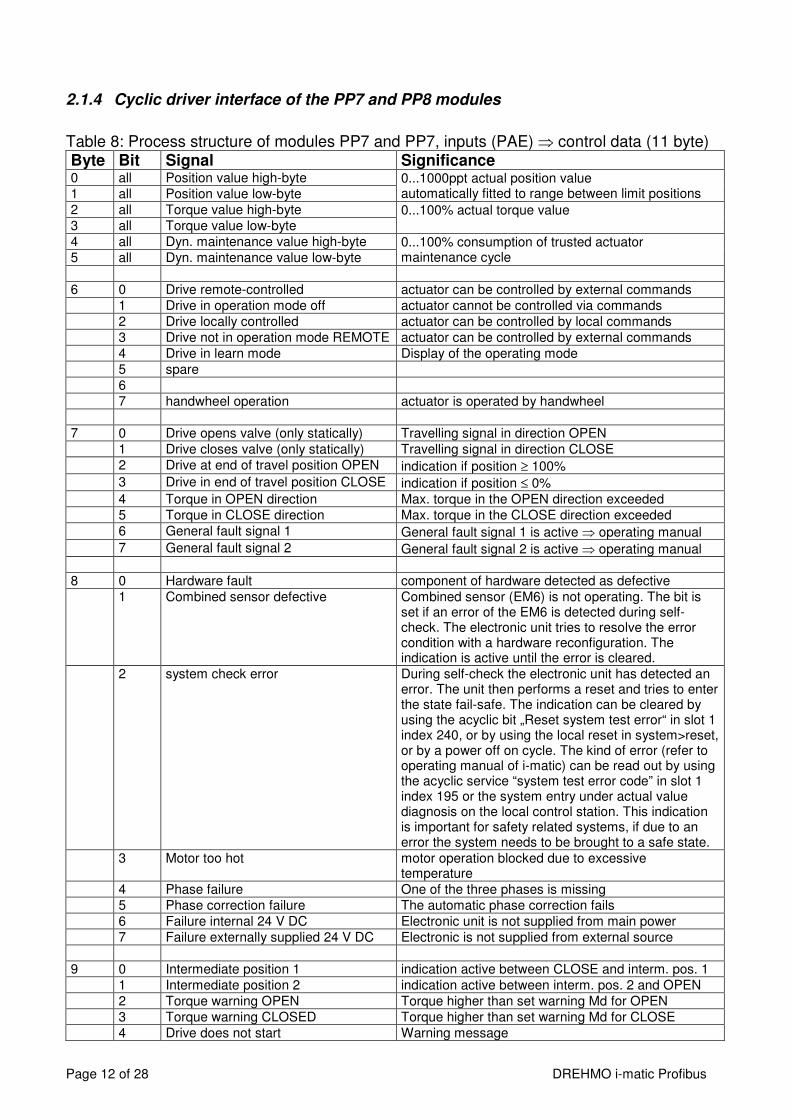
2.1.4 Cyclic driver interface of the PP7 and PP8 modules
Table 8: Process structure of modules PP7 and PP7, inputs (PAE) ⇒ control data (11 byte) Byte Bit Signal Significance 0 all Position value high-byte 0...1000ppt actual position value
automatically fitted to range between limit positions 1 all Position value low-byte
2 all Torque value high-byte 0...100% actual torque value 3 all Torque value low-byte
4 all Dyn. maintenance value high-byte 0...100% consumption of trusted actuator maintenance cycle 5 all Dyn. maintenance value low-byte
6 0 Drive remote-controlled actuator can be controlled by external commands
1 Drive in operation mode off actuator cannot be controlled via commands
2 Drive locally controlled actuator can be controlled by local commands
3 Drive not in operation mode REMOTE actuator can be controlled by external commands
4 Drive in learn mode Display of the operating mode
5 spare
6
7 handwheel operation actuator is operated by handwheel
7 0 Drive opens valve (only statically) Travelling signal in direction OPEN
1 Drive closes valve (only statically) Travelling signal in direction CLOSE
2 Drive at end of travel position OPEN indication if position ≥ 100% 3 Drive in end of travel position CLOSE indication if position ≤ 0%
4 Torque in OPEN direction Max. torque in the OPEN direction exceeded
5 Torque in CLOSE direction Max. torque in the CLOSE direction exceeded
6 General fault signal 1 General fault signal 1 is active ⇒ operating manual 7 General fault signal 2 General fault signal 2 is active ⇒ operating manual
8 0 Hardware fault component of hardware detected as defective
1 Combined sensor defective Combined sensor (EM6) is not operating. The bit is set if an error of the EM6 is detected during self-check. The electronic unit tries to resolve the error condition with a hardware reconfiguration. The indication is active until the error is cleared.
2 system check error During self-check the electronic unit has detected an error. The unit then performs a reset and tries to enter the state fail-safe. The indication can be cleared by using the acyclic bit „Reset system test error“ in slot 1 index 240, or by using the local reset in system>reset, or by a power off on cycle. The kind of error (refer to operating manual of i-matic) can be read out by using the acyclic service “system test error code” in slot 1 index 195 or the system entry under actual value diagnosis on the local control station. This indication is important for safety related systems, if due to an error the system needs to be brought to a safe state.
3 Motor too hot motor operation blocked due to excessive temperature
4 Phase failure One of the three phases is missing
5 Phase correction failure The automatic phase correction fails
6 Failure internal 24 V DC Electronic unit is not supplied from main power
7 Failure externally supplied 24 V DC Electronic is not supplied from external source
9 0 Intermediate position 1 indication active between CLOSE and interm. pos. 1
1 Intermediate position 2 indication active between interm. pos. 2 and OPEN
2 Torque warning OPEN Torque higher than set warning Md for OPEN
3 Torque warning CLOSED Torque higher than set warning Md for CLOSE
4 Drive does not start Warning message
Page 13 of 28 DREHMO i-matic Profibus
Byte Bit Signal Significance 5 direction monitor actuator turns correctly = 0, actuator turns wrong way
= 1
6 Maintenance required Permitted operating data is exceeded ⇒ see operation manual
7 spare
10 0 data transmission on channel 1 valid data transmission is carried out on channel 1
1 data transmission on channel 2 valid data transmission is carried out on channel 2
2 channel 1 active transmission line only commands from channel 1 are performed
3 channel 2 active transmission line only commands from channel 2 are performed
4 Process input 1 State of digital input 1
5 Process input 2 State of digital input 2
6 Process input 3 State of digital input 3
7 Process input 4 State of digital input 4
Table 9: Process structure of modules PP7 and PP8, outputs (PAA) ⇒ control data (4 byte) Byte Bit Signal Significance 0 All Setpoint value high byte Setpoint value 0...1000 ppt
automatically fitted to range between limit positions 1 All Setpoint value low byte
2 0 Fault acknowledge Reset mechanism for dedicated stored faults (e.g. torque, phase errors) as described in actuator operation manual - valid for software revisions greater or equal V01.05.0048
3 0 Automatic mode Activates the integrated 3-point position controller (actuator is positioned according to comparison of setpoint value with position value)
1 Stop Stops the drive if automatic mode = 0
2 Close Closes the valve if automatic mode = 0
3 Open Opens the valve if automatic mode = 0
4 Emergency Shutdown (ESD) Activates the emergency shutdown of the drive
5 Timer operation active Activates the timer operation if set to external
6 Release of local control Enables local operation
7 Change of channel Changes the transmission channel in case of a rising edge, if transmission takes place on the new channel
2.1.5 Function Fail-Safe
If the watchdog-time configured by the master station expires, the PROFIBUS-ASIC indicates an error to the main processor. According to the settings of the parameters of the fail-safe function (refer to operating manual i-matic, parameter fail-safe), after the specified time-delay the function is activated.
2.1.6 Error indications
As well as using the bit “fault acknowledge” within the process structure error-indications can be acknowledged according to the error:
- By moving into the opposite direction in case of “tripping torque exceeded” or “actuator start monitor”.
- Error is indicated only as long as it occurs: All other errors, e.g. motor overtemperature
Page 14 of 28 DREHMO i-matic Profibus
2.2 Acyclic driver interface:
The access on the acyclic parameters is possible by means of the DPV1 services MSAC1 and MSAC2. The used data types are conform to the PROFIBUS-PA definitions.
A detailed listing of the overall acyclic data model is not given here, because the access out of the PLC or DCS system is either done via a DDL (Device Description Language) or a DTM (Device Type Manager). DDL or DTM can be downloaded from the DREHMO homepage or can be ordered free of charge via the DREHMO service.
Page 15 of 28 DREHMO i-matic Profibus
3 Electrical connection
3.1 Mains
Work on electrical equipment and electrical installation of actuators must be carried out by electricians or under supervision by fully qualified engineers, in accordance with the valid electrical regulations. Wiring should be carried out according to the enclosed wiring diagram. The overcurrent protection of the actuator has to be installed inside the power network. For rated values, see design data.
Pay special attention to the PE-connection of the actuator (refer to wiring diagram). Electrical protection is not obtained until all covers are closed.
3.2 Actuators i-matic for normal atmosphere – DiM-X0X
3.2.1 Copper cable connection
Wiring is carried out according the wiring diagram supplied with the actuator. The connection of standard devices (Non Ex-proofed-devices) has to be carried out via the bus circuit board DiM-10. The locations of the connection terminals are shown in the following picture. The picture shows the version for the redundant bus connection. Depending on the configuration it is possible, that the components for BUS 2 and the optional process inputs do not exist.
Picture 4
BUS 1 BUS 2
Mains supply connector (connection on backside)
Shield Ext. 24V
Shield BUS 2
Shield BUS 1
Terminator BUS 1
Terminator BUS 2
Optional process inputs
24V DC input
Page 16 of 28 DREHMO i-matic Profibus
The circuit board is equipped with different connection terminals. The small connection terminal can be used for a wire cross section of up to 0,5mm², the large connection terminal for up to 2,5mm². Table 10: Process structure
Connection terminal small – bus connection , optional process inputs
AWG 20 - 28 0.08 – 0.5 mm²
Connection terminal large – external 24V input
AWG 12 - 20 0.5 – 2.5mm²
The bus circuit board DiM-10 is equipped with RS485 transceivers. For that reason the internal length of the stub cable does not affect the signal quality of the bus segment.
Pay attention to the ESD protection of the bus circuit board. Especially good personal earthing is required. If the bus circuit board is disassembled from its housing transport and storage must meet ESD requirements.
3.2.2 Bus cable
Connection data: Strip length: 5 to 6 mm Wire insertion angle relative to PCB: 40° Connection technology: CAGE CLAMP® PCB terminal with slider (WAGO series 218) Cross section (solid-conductor): 0.08 to 0.5 mm²; AWG 28 to 20 Cross section (multi-conductor): 0.08 to 0.5 mm²; AWG 28 to 20 Cross section (multi-conductor): up to 0.25 mm², AWG 28 to 23 (ferrule without plastic shroud) Connection:
- Insertion of the PROFIBUS cable trough the cable glands - The shielding clamps for the PROFIBUS cables have to be removed - The PROFIBUS cable and wires have to be prepared according the following
drawing
all measurements in mm
Picture 5: Preparation of the PROFIBUS cable and wires
Page 17 of 28 DREHMO i-matic Profibus
without ferrule with ferrule
Picture 6: PROFIBUS cable (solid-conductor) without ferrule Picture 7: PROFIBUS cable (multi-conductor) with ferrule
- In order to open the terminal contact, the slider has to be pushed forward or the
contact spring (in front of the slider) has to be pushed down with a screwdriver (blade width 2.5 to 3.5 mm)
- The PROFIBUS wire has to be inserted in an angle of approximately 40° relative to the PCB board plane into the terminal. The slider has to be pushed backwards afterwards to fasten the conductor (if a ferrule without plastic shroud is used, due to the commonly ferrule length of approx. 7mm, the conductor isolation doesn’t immerge totally inside the terminal inlet).
Picture 8: PROFIBUS terminals - The shielding of the PROFIBUS cable has to be tightened securely by means of the
respective cable clamps - The cable glands have to be fastened with the prescribed torque value in order to
guarantee the specified IP grade.
Page 18 of 28 DREHMO i-matic Profibus
For the crimping of the ferrules we recommend the usage of the crimping tool from company WAGO - Variocrimp 4. Uniform, compact crimping on all four sides for high conductor retention is best suited for the used terminals.
Picture 9: Crimping tool from company WAGO - Variocrimp 4
3.2.3 Shielding connection
The strain relief clamps for the PROFIBUS cable and the 24V external supply cable may be used for the cable shielding – instead of the preferred usage of EMC cable glands. The strain relief clamps are electrical connected via a RC combination to the housing. By means of this, highly frequent signals can be deflected to the housing. Current flow over the shielding due to stray electric currents in the overall plant installation can be avoided. In case of a good potential equalization between the connected field devices, the RC combinations can be short-circuit via the switches S3, S4, S5 in order to have an optimized conduction of possible disturbance signals from the cable shield to the housing.
3.2.4 Active bus termination
RS485 segments have to be terminated and conditioned at the beginning and the end in order to define the signal levels and avoid signal reflections. On the appropriate actuators, the termination switch S1 for BUS1 and S2 for BUS2 has to be in position „TERM“ (termination active). If the termination is active, the outgoing PROFIBUS signal is decoupled from the incoming signal. By means of this, subsequent field devices are disconnected from the master. If subsequent field devices are existing, the termination switch S1 resp. S2 have to be in the position „IN=OUT“ (termination inactive).
Active conditioning of the fieldbus signals in case of activated termination is only given, if the actuator electronic is powered via the mains power connection or the optional existing external 24V DC supply.
If the actuator is equipped with a conventional I/O interface in parallel to the PROFIBUS connection, there is a separate intermediate connector housing mounted between the compact plug cover and the actuator housing. By means of this, additional wiring space and additional available cable entries are given. Separate connectors for the conventional input and output signals according to the wiring diagram are mounted on an additional PCB.
Picture 10: Intermediate connector housing with the integrated PCB connector board for
the conventional I/O signals The mains power connector in those applications is no longer mounted inside the compact plug cover. Instead it is mounted on the connector board for the conventional I/O signals inside the intermediate connector housing. The PROFIBUS signals are wired from the actuator housing side towards the compact plug cover side through the intermediate housing via an additional D-Sub connector cable.
3.2.6 Interface with fibre optic connection
For fibre optic connection please refer to the separate manual (BA_Matic_LWL).
Page 20 of 28 DREHMO i-matic Profibus
3.3 Connection of PROFIBUS to drives as per ATEX for device category 2 G/D
3.3.1 Connection with copper cable
The connection of the profibus signal lines (A, B) have to be done on the appropriate terminals in the termination compartment. In combination with terminal connection a possibly necessary T-piece may be made up by means of using the available double terminals (A1-A1, B1,-B1, A2-A2, B2-B2) which are electrically connected. In combination with the compact plug connector the incoming and outgoing signals are connected at the same terminal.
Picture 11: Connection of two Profibus systems to an i-matic drive: channel 1: leading to the next device channel 2: last device on the segment (terminator activated) The bus terminator always has to be provided near or downstream of the last bus device for correct bus termination. If the last bus device is an i-matic type DREHMO actuator, the terminator can be activated by connecting terminals Tx+ with Bx and Tx- with Ax (see Picture 11), (x = number of channel). Devices for use in explosive areas have a spur length of approximately 40 cm for each channel.
⇒ Observe the maximum allowed spur length per segment! (Refer to section 6.1)
Page 21 of 28 DREHMO i-matic Profibus
3.3.2 Connection of fibre optic cable
Devices of category 2 G/D for explosive areas have the connection solely made by rail mounted screw terminals. The fibre optic converter3) inside the extended safety compartment is powered by the electronic unit. The converter is pressure proof sealed, and the optical interface is intrinsically safe. Actuators can be fitted with single line fibre optic interfaces (e.g. line or star structure), or with a redundant fibre optic interface for a ring structure. The breakout has to be put inside the compartment. It is therefore important to keep the size of the breakout small enough to be able to push it through a cable gland of the size M20. The standard connector is of type F-SMA. The following pictures show the inside of the wiring compartment.
Picture 12: Connection with fibre optic interface - terminals Picture 13: Connection with fibre optic interface – fibre optic cable
3.4 Troubleshooting
Some possible failures are shown below: - The drive gives no message to the bus:
Have the correct terminals been used? Have wires A and B been confused? Is voltage supply OK? Is bus termination correct (bus connection only at ends of segment)? Is the station address assigned only once? Is the station address higher than the highest station address (HSA) of the stations already working?
- The drive is disturbing when other stations are connected: Have the correct terminals been used? Have wires A and B been confused? Have the values for minTSDR and maxTSDR been adapted to other stations?
- Drive cannot be connected to the master station: (analyse fault message, if possible) Is there already a connection to another station? Are the address parameters correct?
Page 22 of 28 DREHMO i-matic Profibus
3.4.1 Connection status diagnostics at the LC-Display
An icon style status indication of the communication status of the interface is given in the i-matic display. For a single channel interface card, only one icon is shown in the display. For two channel cards, two symbols are displayed. In this case, the upper symbol displays the situation of channel 1 and the lower symbol displays the situation of channel 2. The active channel - the channel from which the actuator control signals are derived from - is displayed inverse.
Picture 14: Diagnostics at the LC-Display
Table 11: Symbols for connection status diagnostics Icon Meaning
The slave resides in the state baud rate search. No valid Profibus telegrams are detected. Either the master is not active or there are wiring problems.
A valid baud rate was detected, but the slave is not parameterized by the master or the parameterization is wrong.
The Slave resides in the state data exchange. (DPV0).
The Slave Watchdog is exceeded. The actuator resides in the state Fail-safe, if this is parameterized.
The slave received a global control clear from the master. Normally the PLC of the master or the interface unit resides in the state STOP.
3.4.2 Failures during DPV0 connection start-up sequence
A failure in the DPV0 connection start-up sequence due to errors in the parameterization telegram occurs is signalized by the error message 25: PB PRM Error. Further diagnosis is given in the menu item: Actual values / Diagnosis -> Interface -> Profibus -> Param. Error code. The following values can be displayed:
Table 12: Error codes for status diagnostics Value Description 0 No Error is pending. 1 Invalid bit is set in the 3 DPV1 bytes of the parameterization telegram. 2 The length of the parameterization telegram is invalid. 3 The PRM_CMD part for the parameterization of the DPV2 redundancy is invalid. 4 The length of the PRM_CMD part is invalid or the actuator does not support the
required DPV2 functionality. 5 The TIME_AR part for the parameterization of the time stamping and distribution is
invalid. 6 The length of the TIME_AR part for the parameterization of the time stamping and
distribution is invalid or the actuator does not support the needed DPV2 functionality. 9 A block with a block ID that is not supported exists inside the extended
parameterization telegram. 10 The block lengths within the extended parameterization are inconsistent.
Fieldbus status indication icon
Page 23 of 28 DREHMO i-matic Profibus
4 Interface to external sensor - process inputs
Actuators of type i-matic can be equipped with an optional interface for an external sensor. The interface consists of four discrete inputs (24 V DC), and two analogue inputs (4...20mA). The discrete inputs with common ground are galvanically isolated from the electronic potential by optocouplers. The nominal current of the discrete inputs is 12 mA for an input voltage of 24 V DC. Via the actuator parameterization it is possible to assign various different functions to the digital inputs. The interaction behaviour of these functions in respect to the commands coming via the PROFIBUS interface can be influenced by means of the remote priority parameterization. Additional information is given in the actuator instruction manual. The following picture shows the structure of the discrete inputs.
Picture 15: digital process inputs The analogue inputs are connected to the electronic potential. The following pictures show examples of how to use the inputs:
Picture 16: connection with two wires Picture 17: connection with three wires Picture 18: connection with four wires
Keep in mind: The signals of the process inputs are only transferred to the master station if the modules PP5 or PP6 are used.
Page 24 of 28 DREHMO i-matic Profibus
5 TECHNICAL DATA
5.1 Characteristics of the field bus interface
Identification no.: 0x0824 for master-slave redundant systems 0x0825 for other DP or DPV1 drives Baud rate: is defined by the master, max. 1.5MBaud Protocol: as per IEC 61158 and IEC 61784-1 Bus system: RS-485
6 Projecting information
When designing a PROFIBUS system the guidelines of the PROFIBUS User Organisation have to be observed. Additionally apply the directive IEC 61158. In the following paragraphs some important extracts are listed.
6.1 Cable system
Specification as per EN 50170:
Cable type A IEC 61158 part 2 (DP)
Wave impedance 135 - 165 Ohm
Distributed capacitance < 30 pF/m
Loop resistance < 110 Ohm/km
Diameter of wire > 0.64 mm
Cross section of wire > 0.34 mm2
Table 13: Specification of cable The following permissible lengths of the line segments are based on the cable parameters listed in table 1: Baud rate 9.6 19.2 93.75 187.5 500 1500 kbit/s
Cable type A 1,200 1,200 1,200 1,000 400 200 m
Table 14: Lengths of segments For a data throughput of up to 500 kbit/s, the cumulative length of all stub cables within a segment should not exceed 6.6 m altogether (compare PNO information, see item 1).
For drives of category 2 G/D the length of the stub cable is about 40 cm – the number of actuators in a segment must not exceed 16.
When laying the cables, the usual conditions for signal cables must be adhered to: - do not install the cables near power cables - the minimum bending radii of the cables used must be observed, as
otherwise shields or wires may be damaged.
Page 25 of 28 DREHMO i-matic Profibus
6.2 Fibre optic system
Using fibre optic cables the distance between two devices can amount up to 1400m (50 µm
core) or 2600 m (62.5 µm core). The maximum number of devices possible in a segment is strongly depending on the transmission speed, and listed in the following table:
transmission speed max. number of devices per segment 9,6 kBd 124
19,2 kBd 124 93,75 kBd 32 187,5 kBd 16 500 kBd 6
1,5 MBd 2 Table 15: Maximum number of devices per segment in a fibre optic system
6.3 PROFIBUS structure using several segments
Due to the RS 485 physical layer used with PROFIBUS systems, the maximum number of devices in a segment is limited to 32. If more devices shall be connected to a master station, or if the distance (refer to table 2) shall be increased without lowering the transmission speed, segments can be installed (independent of segment addresses) using repeaters. In Picture 19 an example of a PROFIBUS system consisting of several segments is shown.
R R
R R
R
R - Repeater
Segment 1 Segment 2
Segment 3
Segment 4 Segment 5
Segment 6
Picture 19: Example of a PROFIBUS system consisting of several segments
Page 26 of 28 DREHMO i-matic Profibus
Picture 20: Example of a segment
6.4 Terminators
The terminators at either end of the segment are of special importance. They serve to close the line with the wave resistance and to determine the rest level.
Picture 21: Terminator
Terminators must be provided on either end of a segment. The use of other types of termination may lead to faults in the PROFIBUS system (ranging from random disturbances of telegrams to complete loss of communication in a segment).
6.5 Grounding of the cable shields if using copper cables
In best practice the shielding of incoming and outgoing cables should be directly connected via EMC cable glands to the actuator housing in order to get most efficient EMC protection. As an alternative for non-EX-proofed actuators it is possible to connect the shielding of the PROFIBUS cable to the strain relief clamps on the PROFIBUS connection board. By means of this alternative it is possible to avoid possible equalisation currents over the cable shielding between connected devices in widespread installations. For this it is possible on the PROFIBUS conection board DIM-10 to separately open the direct grounding connection for the incoming and outgoing cable shields via sliding switches. Instead of the direct grounding connection a R/C filter circuit becomes active. This filter circuit connects the cable shields to ground with high impedance at low frequencies in order to avoid equalisation currents (see picture 22). High frequent signals are connected with low impedance to ground via the capacitor.
Page 27 of 28 DREHMO i-matic Profibus
Picture 22: alternative shield grounding
6.6 Overvoltage protection
When installing bus cables or signal lines outside a building, please note: - Use standard transmission cables in metal tubes earthed on both ends and
connected to each other. At the point of entry into a building, the metal tubes must be integrated in the equipotential bonding system.
- The cable shield must be resistant to lightning-stroke current. Separate surge or lightning protection means according to the actuator wiring diagram may be installed as additional, optional protection.
6.7 GSD file
The current GSD files are available at http://www.drehmo.com ->Downloads -> Software.
7 Bibliography
1) Interesting link:
www.profibus.com Homepage of the PROFIBUS User Organisation with loads of helpful information concerning the PROFIBUS fieldbus system.
2) Description of the explosion proof optical link module: