105
OPERATIONS, INSTALLATION AND MAINTENANCE MANUAL

OperatiOns, installatiOn and Maintenance Manual

Installation, Operation and Maintenance Manual 3
CONTENTS
1 Summary .......................................................................................................................................................7 1.1 General Construction..........................................................................................................................................7 1.2 Standards and specifications ...........................................................................................................................7 1.3 Operating conditions ..........................................................................................................................................8
1.3.1 Normal operating conditions...............................................................................................................8 1.3.2 Special operating conditions...............................................................................................................8
1.4 Safety Features.....................................................................................................................................................9
2 Technical data ..............................................................................................................................................9 2.1 Electrical data .......................................................................................................................................................9 2.2 Dimensions and weights.................................................................................................................................. 10
3 General Construction ................................................................................................................................. 11 3.1 Basic structure and variants ............................................................................................................................ 11
3.1.1 Busbar compartment ........................................................................................................................... 12 3.1.2 Circuit breaker compartment............................................................................................................ 12 3.1.3 Cable connection/VT compartment................................................................................................ 13 3.1.4 Low Voltage Compartment ............................................................................................................... 13
3.2 Withdrawable and fixed equipment ............................................................................................................ 14 3.2.1 Circuit Breaker ....................................................................................................................................... 14 3.2.2 Voltage transformers........................................................................................................................... 17 3.2.3 Current transformers ........................................................................................................................... 17 3.2.4 Voltage Detection System ................................................................................................................. 18 3.2.5 Earthing switch ...................................................................................................................................... 18
3.3 Enclosure and partitioning.............................................................................................................................. 19 3.4 Ventilation of the panels.................................................................................................................................. 19 3.5 The exhaust gas compartment.....................................................................................................................20 3.6 The gas duct........................................................................................................................................................ 21 3.7 Typical Units ....................................................................................................................................................... 22
3.7.1 Incoming panel ..................................................................................................................................... 22 3.7.2 Outgoing panel ..................................................................................................................................... 23 3.7.3 Busbar Tie (Bustie) .............................................................................................................................. 24 3.7.4 Busbar riser............................................................................................................................................ 26 3.7.5 Measurement panel (Client-specific optional) ............................................................................ 27
4 Interlocks.................................................................................................................................................... 28 4.1 Interlock Cross reference table..................................................................................................................... 28
4.1.1 Withdrawable equipment – racking with door open interlock..............................................30 4.1.2 Circuit breaker – racking interlock..................................................................................................30 4.1.3 Circuit breaker – CLOSE interlock...................................................................................................30 4.1.4 Circuit breaker – CLOSE lock............................................................................................................. 31 4.1.5 Withdrawable equipment - latching handles ............................................................................... 31 4.1.6 Socket board interlock ....................................................................................................................... 32 4.1.7 Circuit breaker secondary plug connector coding .................................................................... 32 4.1.8 Withdrawable equipment – door interlock.................................................................................. 33 4.1.9 Earthing switch interlocks ................................................................................................................. 34 4.1.10 Door Interlocks...................................................................................................................................... 35
5 Packing Transport and Storage ............................................................................................................. 38 5.1 Condition on delivery ...................................................................................................................................... 38

4 Installation, Operation and Maintenance Manual
5.2 Packing................................................................................................................................................................. 38 5.3 Transport ............................................................................................................................................................. 39 5.4 Control on receipt............................................................................................................................................. 39 5.5 Intermediate storage .......................................................................................................................................40 5.6 Handling...............................................................................................................................................................40
5.6.1 Handling the Switchgear ...................................................................................................................40 5.6.2 Unpacking and switchboard handling............................................................................................ 41 5.6.3 Handling the removable parts.......................................................................................................... 42
6 Installation ................................................................................................................................................. 43 6.1 Installation - General Information................................................................................................................ 43 6.2 Foundation and switchgear erection..........................................................................................................44
6.2.1 Tightening torque table .....................................................................................................................44 6.2.2 Foundation details ...............................................................................................................................44 6.2.3 Fixing with unistruts foundation Channels...................................................................................46 6.2.4 Fixing with anchoring bolts (Expanding type bolts) ................................................................ 47 6.2.5 Position and fixing the units on the foundation ......................................................................... 47
6.3 Main Busbar Assembly ....................................................................................................................................49 6.4 Unit earthing....................................................................................................................................................... 53 6.5 Installation of Gas Compartment ................................................................................................................. 54 6.6 The gas duct....................................................................................................................................................... 56 6.7 Connection of Inter-unit auxiliary wiring (Bus-wiring) ......................................................................... 57 6.8 Connecting the auxiliary multicore cables................................................................................................ 57
6.8.1 Front bottom entry.............................................................................................................................. 57 6.8.1 Rear bottom entry ............................................................................................................................... 58 6.8.2 Low voltage wiring trough................................................................................................................ 58
6.9 Power cable termination ................................................................................................................................ 59 6.9.1 Cable supports and grommets for single core cables ............................................................... 61 6.9.2 Cable gland for 3 core cables........................................................................................................... 62
6.10 Installation of the decorative end covers .................................................................................................. 63 6.11 Installing the tool rack..................................................................................................................................... 67 6.12 Aligning the door racking access hole to the circuit breaker drive .................................................. 67 6.13 Final check .......................................................................................................................................................... 68 6.14 Circuit name label ............................................................................................................................................. 68 6.15 Extending the switchboard............................................................................................................................ 68
7 Operation ................................................................................................................................................... 69 7.1 Operating Accessories ....................................................................................................................................69 7.2 Circuit breaker positions.................................................................................................................................70
7.2.1 Removed position................................................................................................................................70 7.2.2 Isolated/ test position.......................................................................................................................... 71 7.2.3 Service Position ..................................................................................................................................... 71
7.3 Inserting the Circuit breaker into the panel from the removed position......................................... 72 7.4 Racking the circuit breaker from the isolated/test position to the service position ................... 74 7.5 Withdrawal from service to isolate/test position ................................................................................... 75 7.6 Removal of the circuit breaker from the panel........................................................................................ 75 7.7 Padlocking the shutters .................................................................................................................................. 76 7.8 Operating the circuit breaker in the isolated/test position with door open .................................. 76
7.8.1 Spring charging .................................................................................................................................... 76 7.8.2 Circuit breaker closing........................................................................................................................ 77 7.8.3 Circuit breaker opening...................................................................................................................... 77
7.9 Operating the circuit breaker in the service position with door closed........................................... 77 7.9.1 Manual spring charging...................................................................................................................... 78 7.9.2 Manual switching ON with door closed......................................................................................... 78 7.9.3 Manual switching OFF with door closed....................................................................................... 79
7.10 Electrical Operation.......................................................................................................................................... 79

Installation, Operation and Maintenance Manual 5
7.10.1 Electrical spring charging.................................................................................................................. 79 7.10.2 Switching ON.........................................................................................................................................80 7.10.3 Switching OFF.......................................................................................................................................80
7.11 VT Compartment ............................................................................................................................................... 81 7.11.1 Withdrawable VT .................................................................................................................................. 81
7.12 Earthing ............................................................................................................................................................... 83 7.12.1 Switching ON the earthing switch .................................................................................................. 84 7.12.2 Switching OFF the earthing switch ................................................................................................ 85 7.12.3 Optional Voltage Detection System VDS ..................................................................................... 85
8 Commissioning checks and test programme ...................................................................................... 86 8.1 General checks................................................................................................................................................... 86 8.2 Electrical tests.................................................................................................................................................... 87 8.3 Mechanical Tests ............................................................................................................................................... 87 8.4 Recording............................................................................................................................................................ 88 8.5 Check Lists .......................................................................................................................................................... 89 8.6 Counter Recording ...........................................................................................................................................90
9 General Maintenance................................................................................................................................. 91 9.1 Intervals for inspection, servicing and repairs ......................................................................................... 92 9.2 Inspection............................................................................................................................................................ 92 9.3 Servicing.............................................................................................................................................................. 93
9.3.1 Maintenance in busbar compartment............................................................................................94 9.3.2 Maintenance in cable compartment............................................................................................... 95 9.3.3 Maintenance in circuit breaker compartment ............................................................................. 98 9.3.4 Checking correct operation of the protection relay..................................................................99 9.3.5 Cleaning and checking the auxiliary connections ......................................................................99
9.4 Repairs ............................................................................................................................................................... 100 9.4.1 Switchgear in general ....................................................................................................................... 100
9.5 Testing interlock conditions ........................................................................................................................ 100 9.6 Spare parts, auxiliary materials and lubricants...................................................................................... 100
9.6.1 Spare parts........................................................................................................................................... 100 9.6.2 Accessories, Auxiliary materials and lubricants......................................................................... 101

6 Installation, Operation and Maintenance Manual
Safety Warning
• Only install switchgear and/or switchboards in closed rooms designed and constructed specifically for electrical equipment.
• Ensure that installation, operation and maintenance are carried out by trained and qualified personnel only.
• Fully comply with the legally recognized standards (IEC or local), the local electrical utility and the applicable safety at work regulations.
• Observe the relevant information in this instruction manual for all actions involving operation and maintenance of the switchgear.
• Before working on the Switchgear it is necessary for the operator to ensure that it has been safely disconnected from electrical supplies and that the necessary safety earths have been fitted and a suitable permit to work issued.
• To assist in its safe operation, the equipment is fitted with padlocking facilities which shall be applied as appropriate.
• Ensure that the operating conditions do not exceed the specified data. • Keep the instruction manual accessible to all personnel involved in installation, operation and
maintenance. • Operations not included in the manual must be carried out by or under the supervision of Medelec
Switchgear Ltd. • This manual uses certain terms and symbols to warn about dangers or provide information:
WARNING – Warns about dangerous electrical voltage or contact with voltage.
CAUTION – Warns about risk of injury.
NOTE - Gives important information to avoid damage to equipment
General instructions
Medelec Switchgear Ltd has done its utmost to inform users as accurately and as fully as possible concerning any dangers involved in using the equipment. Users are responsible for supervising the implementation of the instructions contained in this manual.
Before commencing work and after the completion of work any control switches shall be left in the appropriate positions.
Should the operator require any guidance or advice regarding the equipment this can be obtained by contacting Medelec Switchgear Ltd.
Our policy is one of continuous product development and the right is reserved to supply equipment, which may vary slightly from that described.

Installation, Operation and Maintenance Manual 7
1 Summary 1.1 General Construction
is a three-phase, metal-clad, air insulated, internal arc certified switchgear of modular construction. All the units are factory assembled, type-tested and suitable for indoor applications up to 12kV. The units are designed as modules and are fitted with a single busbar system. The withdrawable parts are equipped with vacuum circuit breakers. Existing units are easily extendable from both sides if the site permits.
All the unit compartments have metal segregations between them and the live parts are insulated in air.
The cubicles are all factory-cabled. The installation requires only the external power and auxiliary connections and the wiring between the various units, together with the assembly of the main busbar, the exhaust gas Compartment on top of each unit and the decorative end covers.
The normal service operations are performed from the switch-board front with all the doors closed. Only maintenance and replacement of spare parts require opening of the front doors. All functions are easily accessible by the operator.
is for use on distribution networks having the highest system voltage up to 12kV, a short circuit current rating up to 31.5kA, a maximum full load current of 2000A and a lightning impulse level up to 75 kVp (BIL).
1.2 Standards and specifications switchgear panels comply with the standards and specifications
for factory-assembled, metal-enclosed and type tested high voltage switchgear to IEC 62271-1 and -200.
The switchgear panels have the following degrees of protection: IP4X for the enclosure and IP2X for the partitions to IEC 60529.
switchboards are arc-proof and comply with IEC 62271 Standards Accessibility Class AFLR.
The components used comply with standards:
●IEC 62271-100:High-voltage alternating current circuit breakers
●IEC 62271-102:Alternating current disconnector and earthing switches
●IEC 61869-2:Instrument transformers -part 2:Current transformers
●IEC 61869-3: Instrument transformers - part 3: Voltage transformers
●IEC 62271-206 For the voltage presence indication system

8 Installation, Operation and Maintenance Manual
1.3 Operating conditions
1.3.1 Normal operating conditions The switchgear is suitable for normal operating conditions for indoor switchgear and switchboards in accordance with IEC 60694. The installation may only be operated if the area complies with the requirements of the IEC 62271-1 standard. (See also paragraph 6.1) Additional conditions may also apply. These are laid down in the operating instructions.
The following limit values, among others, apply:
Ambient temperature:
Maximum +40 °C Maximum 24 h average +35 °C Minimum -5 °C
The maximum site altitude is 1000 m above sea level.
1.3.2 Special operating conditions Special operating conditions must be discussed with the manufacturer in advance, for example:
• At site altitudes above 1000 m, the effects of the reduction in dielectric strength of the air on the insulation level must be taken into account.
• Increased ambient temperatures will limit the current carrying capacity of the busbars. Heat dissipation in the switchgear panel can be assisted by fitting additional ventilation facilities.
All units are equipped with self-regulating heaters to eliminate the possibility of moisture condensation due to high humidity and/or major rapid temperature fluctuations.

Installation, Operation and Maintenance Manual 9
1.4 Safety Features In general it will not be necessary to take special safety measures when operating the switchgear. It is advisable, however, to wear suitable ear protection when there is repeated switching.
The switchgear is provided with the following safety features:
• A steel sheet enclosure to protect against contact with live components.
• Compartments with earthed steel walls. • Positively driven metallic shutters shielding live parts when a
withdrawable part is withdrawn or removed. • Internal arc classification testing has been conducted and an
exhaust gas Compartment provided to allow the safe exhaust of gases outside of the switch room through a gas duct.
• Mechanical and electrical interlocks to prevent unintentional switching.
• Provision for locking or padlocking on the circuit breakers, earthing switches and shutters.
• Separation between circuit breaker, cable and busbar Compartments.
• Visible indication of the earthing switch status. • Special equipment intended for the earthing of cables and
busbars. • A continuous earthing bar extending the full length of the
installation. • Locks on panel doors. • Warnings on equipment to alert personnel of possible dangers.
2 Technical data
2.1 Electrical data Rated voltage kV 12
Rated power frequency withstand voltage kV 28
Rated lightning impulse withstand voltage kV 75
Rated frequency Hz 50/60
Rated current of busbars A …2000
Rated current of circuit breaker branches A …2000
Rated peak withstand current kA …80
Rated short-circuit breaking current of circuit breaker
kA …31.5
Rated duration of short-circuit current s 3

10 Installation, Operation and Maintenance Manual
2.2 Dimensions and weights
Rated Voltage (Panel width)
Rated Current Dimension (mm) Weight (kg)
A/A1 B C D
12kV (600mm) …1250A 600 2050 2510 1550 500
12kV (750mm) 2000A 750 2050 2510 1550 570
CAUTION: The weights indicated are approximate and do not include contract variable non-standard components or apparatus.

Installation, Operation and Maintenance Manual 11
3 General Construction
3.1 Basic structure and variants The panel with withdrawable vacuum circuit breaker is divided into circuit breaker compartment, busbar compartment, cable compartment and low voltage compartment for the control and protection equipment. The also contains other compartments used for the channelling of gases in the case of an internal arc, routing of auxiliary wiring between units and also segregation of the withdrawable VT’s.
For busbar isolation, two panels are necessary, the Bustie with the withdrawable circuit breaker part and a bus riser panel. The can also be supplied with optional busbar metering and earthing.
A Auxiliary circuit wiring duct
B Low voltage compartment
C Circuit breaker Compartment
D Withdrawable circuit breaker
E Voltage transformer Compartment
F Withdrawable voltage transformer
G Internal Arc Exhaust Gas Compartment
H Busbar Compartment
I Current transformer
J Earthing switch
K Feeder cable Compartment

12 Installation, Operation and Maintenance Manual
3.1.1 Busbar compartment
The busbars have a flat cross-section made of copper and are laid in sections from panel to panel. They are held by flat branch conductors and no special connection clamps are needed. No insulation is required. The busbar compartment is accessible from the rear of the panel or from the top depending on the installation layout. When accessed from the rear top cover, a perforated plate segregates the accessed area from the cable compartment thus providing LSC2B partitioning.
3.1.2 Circuit breaker compartment
The circuit breaker compartment contains all the necessary equipment for the operation of the withdrawable part and the panel. Like the busbar compartment, it is metallically partitioned on all sides. The metal shutters, covering the fixed contacts provide the necessary separation from the main contacts. These are opened by means of brackets mounted on the withdrawable circuit breaker when inserting into the service position, and are closed when the latter is removed.
In the isolated/test position, the withdrawable part is still completely inside the panel with the door closed. The ON/OFF pushbutton located on the circuit breaker, and the mechanical indicators for OPEN/CLOSE and CHARGED/DISCHARGED can be observed through an inspection window if the circuit breaker is in service position.
All operations, including racking, charging and switching, are carried out with the doors closed. The socket for the control wiring is plugged in the circuit breaker compartment and mechanically interlocked with the Circuit Breaker racking.
The CB door also includes a circuit single line diagram.
Installation, Operation and Maintenance Manual 13
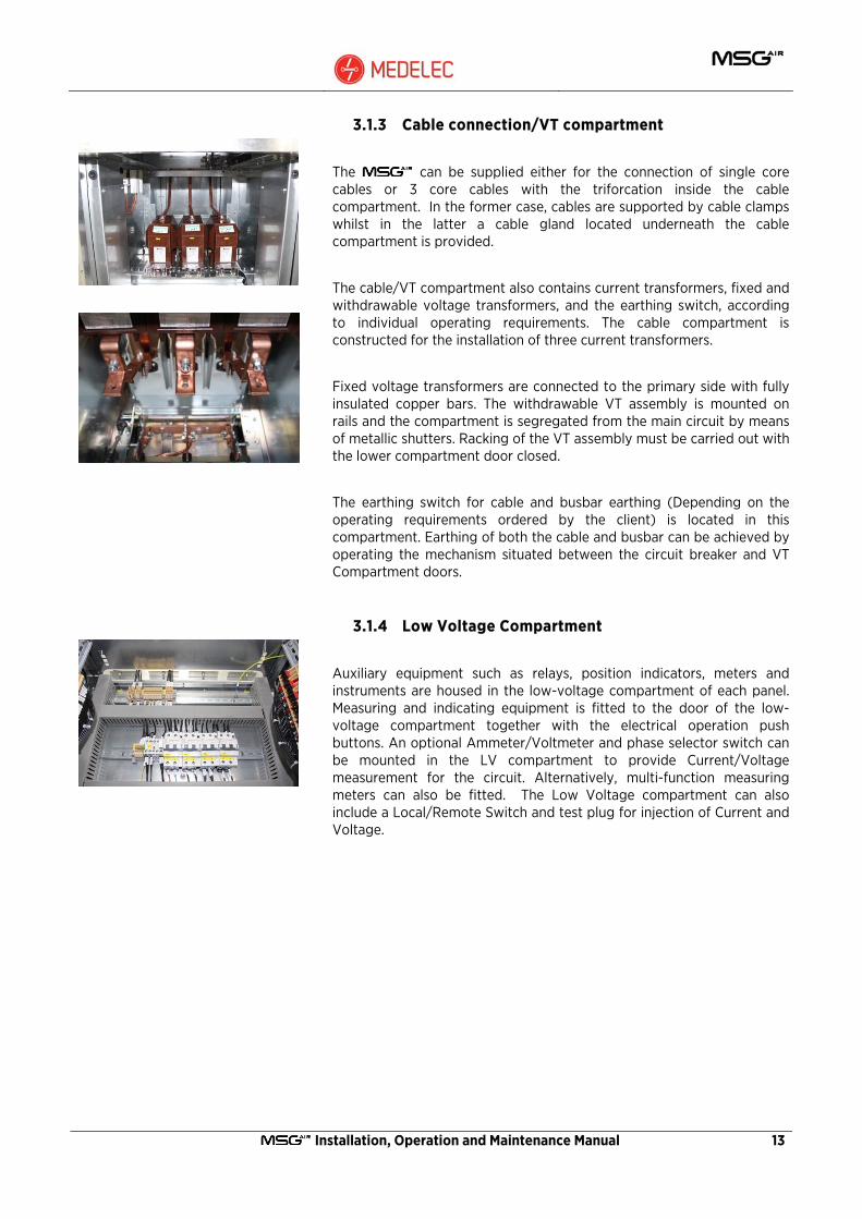
3.1.3 Cable connection/VT compartment
The can be supplied either for the connection of single core cables or 3 core cables with the triforcation inside the cable compartment. In the former case, cables are supported by cable clamps whilst in the latter a cable gland located underneath the cable compartment is provided.
The cable/VT compartment also contains current transformers, fixed and withdrawable voltage transformers, and the earthing switch, according to individual operating requirements. The cable compartment is constructed for the installation of three current transformers.
Fixed voltage transformers are connected to the primary side with fully insulated copper bars. The withdrawable VT assembly is mounted on rails and the compartment is segregated from the main circuit by means of metallic shutters. Racking of the VT assembly must be carried out with the lower compartment door closed.
The earthing switch for cable and busbar earthing (Depending on the operating requirements ordered by the client) is located in this compartment. Earthing of both the cable and busbar can be achieved by operating the mechanism situated between the circuit breaker and VT Compartment doors.
3.1.4 Low Voltage Compartment
Auxiliary equipment such as relays, position indicators, meters and instruments are housed in the low-voltage compartment of each panel. Measuring and indicating equipment is fitted to the door of the low-voltage compartment together with the electrical operation push buttons. An optional Ammeter/Voltmeter and phase selector switch can be mounted in the LV compartment to provide Current/Voltage measurement for the circuit. Alternatively, multi-function measuring meters can also be fitted. The Low Voltage compartment can also include a Local/Remote Switch and test plug for injection of Current and Voltage.

14 Installation, Operation and Maintenance Manual
3.2 Withdrawable and fixed equipment
3.2.1 Circuit Breaker
The circuit breaker used on the switchgear is the VD4 type supplied by ABB. (Other circuit breaker types such as the HD4 and VM1 can also be provided on request). VD4 circuit breakers are provided with vacuum interrupters. This assembly is mounted on a truck with built-in racking mechanism.
Electrical control signals are supplied from the low-voltage compartment via a secondary plug. Mechanical and electrical interlocks prevent unintentional switching.
Refer to separate Operations and Maintenance Manual for the Circuit Breaker.
3.2.1.1 Circuit breaker positions
Removed position
Isolated / test position
Service position
The unit is in the removed position when:
• The compartment door is open
• The unit is moved in-front of the panel ready for insertion, or
• The unit is moved completely out of the panel.
The unit is in the isolated/test position, when:
• The unit is in the panel but moved to the front of the compartment,
• The primary contacts are disconnected, the shutters are closed and
• The secondary plug is connected (control over the operation of the unit is now possible )
• The compartment door can be opened.
The unit is in the service position, when:
• The unit is fully inserted and engaged into the compartment.
• The primary contacts are connected and
• The secondary plug is connected
• The compartment door cannot be opened.
WARNING: In emergency situations, the door interlock can be defeated with the use of tools. (See section 4.1.10.2)

Installation, Operation and Maintenance Manual 15
3.2.1.1 Typical circuit breakers
630A
1250A
2000A
3.2.1.2 Circuit breaker controls
The withdrawable circuit breaker forms a complete module consisting of vacuum circuit breaker, isolating contact arm and contact system, the secondary wiring plug together with all the mechanical controls and indication systems required.
All operations and indication can be carried out locally from the front of the breaker (with compartment door closed when in the service position). The breaker front and supporting truck also house the mechanical locking/interlocking facilities with the compartment equipment and door. It also has the operation counter.

16 Installation, Operation and Maintenance Manual
3.2.1.3 Circuit breaker switch position Indication
Red and green status indication lamps on the Low Voltage Compartment door are used to indicate the OPEN/CLOSE status of the circuit breaker.
In case of a power outage, the status of the breaker can also be viewed through the polycarbonate window of the breaker Compartment.
Mechanical flags on the circuit breaker front panel will give the status of the circuit breaker including the status of the spring charge.
Secondary control wiring Plug
Mechanical ON push-button
Key lock OFF position
Mechanical OFF push-button
Sliding truck racking-interlock handle
Door-circuit breaker interlock
Mechanical racking drive
Circuit breaker rating plate
Mechanical switch position indicator
Mechanical spring charge indicator
Mechanical rotary spring charging drive
Mechanical operation counter
Installation, Operation and Maintenance Manual 17
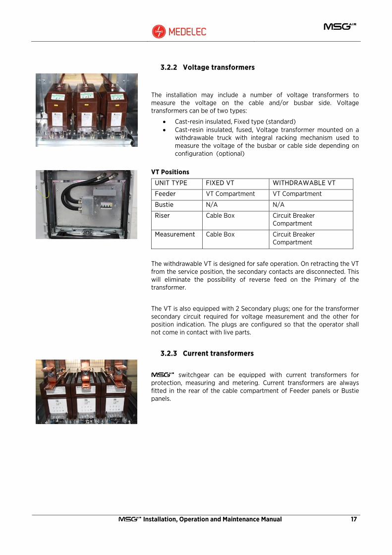
3.2.2 Voltage transformers
The installation may include a number of voltage transformers to measure the voltage on the cable and/or busbar side. Voltage transformers can be of two types:
• Cast-resin insulated, Fixed type (standard) • Cast-resin insulated, fused, Voltage transformer mounted on a
withdrawable truck with integral racking mechanism used to measure the voltage of the busbar or cable side depending on configuration (optional)
VT Positions
UNIT TYPE FIXED VT WITHDRAWABLE VT
Feeder VT Compartment VT Compartment
Bustie N/A N/A
Riser Cable Box Circuit Breaker Compartment
Measurement Cable Box Circuit Breaker Compartment
The withdrawable VT is designed for safe operation. On retracting the VT from the service position, the secondary contacts are disconnected. This will eliminate the possibility of reverse feed on the Primary of the transformer.
The VT is also equipped with 2 Secondary plugs; one for the transformer secondary circuit required for voltage measurement and the other for position indication. The plugs are configured so that the operator shall not come in contact with live parts.
3.2.3 Current transformers
switchgear can be equipped with current transformers for protection, measuring and metering. Current transformers are always fitted in the rear of the cable compartment of Feeder panels or Bustie panels.

18 Installation, Operation and Maintenance Manual
3.2.4 Voltage Detection System
The voltage indicator is mounted on the low-voltage compartment door. The voltage indicator is connected to a capacitive divider inside each of the Current transformers. When the cable is live the indicator lamps will light up.
3.2.5 Earthing switch
Each panel is fitted with a short circuit proof earthing switch fitted either to the cable side and/or the busbar side. The earthing switch connects the points of the cable/busbar with the earthing busbar. A mechanical interlock ensures that the earthing switch is always open when the circuit breaker is in the connected position.
The earthing switch can be closed only with the circuit breaker in the isolated/test position or completely removed.
The earthing switch can be key locked in both the open (optional) and closed (standard) position.
Earth switch position can be viewed either from the position of the drive mechanism or by means of the appropriate indicator on the switch mechanism when viewed through the viewing window located underneath the circuit breaker door.
Installation, Operation and Maintenance Manual 19
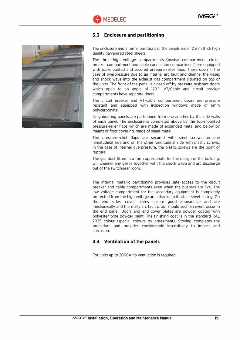
3.3 Enclosure and partitioning
The enclosure and internal partitions of the panels are of 2 mm thick high quality galvanised steel sheets.
The three high voltage compartments (busbar compartment, circuit breaker compartment and cable connection compartment) are equipped with top-mounted and secured pressure relief flaps. These open in the case of overpressure due to an internal arc fault and channel the gases and shock wave into the exhaust gas compartment situated on top of the units. The front of the panel is closed off by pressure resistant doors which open to an angle of 120°. VT/Cable and circuit breaker compartments have separate doors.
The circuit breaker and VT/cable compartment doors are pressure resistant and equipped with inspection windows made of 6mm polycarbonate.
Neighbouring panels are partitioned from one another by the side walls of each panel. The enclosure is completed above by the top-mounted pressure-relief flaps which are made of expanded metal and below by means of floor covering, made of sheet metal.
The pressure-relief flaps are secured with steel screws on one longitudinal side and on the other longitudinal side with plastic screws. In the case of internal overpressure, the plastic screws are the point of rupture.
The gas duct fitted in a form appropriate for the design of the building, will channel any gases together with the shock wave and arc discharge out of the switchgear room.
The internal metallic partitioning provides safe access to the circuit
breaker and cable compartments even when the busbars are live. The low voltage compartment for the secondary equipment is completely protected from the high voltage area thanks to its steel-sheet casing. On the end sides, cover plates ensure good appearance and are mechanically and thermally arc fault proof should such an event occur in the end panel. Doors and end cover plates are powder coated with polyester type powder paint. The finishing coat is in the standard RAL 7035 colour (special colours by agreement). Stoving completes the procedure and provides considerable insensitivity to impact and corrosion.
3.4 Ventilation of the panels
For units up to 2000A no ventilation is required.

20 Installation, Operation and Maintenance Manual
3.5 The exhaust gas compartment
The highly unlikely event of an internal arc in a switchboard generates overpressures in the relative compartment with the emission of hot gases and particles of material.
This release must be suitably controlled in order to protect people and objects in the immediate vicinity from any injury or damage. The exhaust gas compartment of the is suitably sized to handle the pressures and thermal shocks sustained during such events.
CAUTION: When switchboard is placed on open cable trenches make sure that any unused trenches are closed so that hot gases are not released from these openings.
The standard arc-proof version features a Compartment in the top part for collecting and conveying internal arc gases. The Compartment ends must be extended externally to a safe area, by means of a gas duct, so as to safeguard operators working either in front of the switchboard or in the accessible sides and also prevent deposit of gases and overpressures inside the installation room. This configuration complies with IEC 62271 Standard accessibility Class AFLR.
Evacuation of the gases in the switchboard takes place as follows.
• Internal arc in the circuit breaker compartment (2) – the flap (3) opens up and the gas is conveyed into the Compartment (1).
• Internal arc in the busbar compartment (6) – the flap (7) opens up and the gas is conveyed into the Compartment (1).
• Internal arc in the feeder compartment (4) – the flap (5) opens up and the gas is conveyed into the Compartment (1).
The gas flows through the Compartment (1) and comes out of the external outlets through the gas duct.
Installation, Operation and Maintenance Manual 21
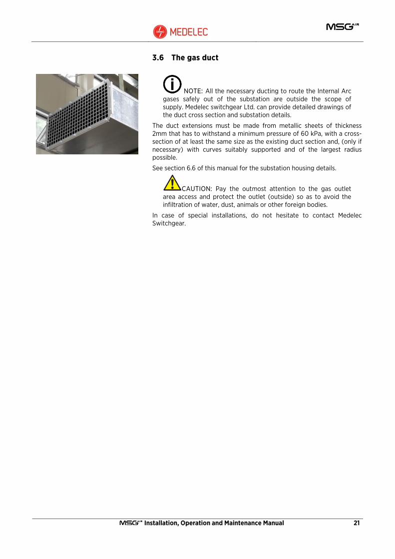
3.6 The gas duct
NOTE: All the necessary ducting to route the Internal Arc gases safely out of the substation are outside the scope of supply. Medelec switchgear Ltd. can provide detailed drawings of the duct cross section and substation details.
The duct extensions must be made from metallic sheets of thickness 2mm that has to withstand a minimum pressure of 60 kPa, with a cross-section of at least the same size as the existing duct section and, (only if necessary) with curves suitably supported and of the largest radius possible.
See section 6.6 of this manual for the substation housing details.
CAUTION: Pay the outmost attention to the gas outlet area access and protect the outlet (outside) so as to avoid the infiltration of water, dust, animals or other foreign bodies.
In case of special installations, do not hesitate to contact Medelec Switchgear.
22 Installation, Operation and Maintenance Manual
3.7 Typical Units
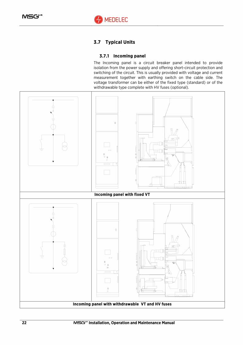
3.7.1 Incoming panel The Incoming panel is a circuit breaker panel intended to provide isolation from the power supply and offering short-circuit protection and switching of the circuit. This is usually provided with voltage and current measurement together with earthing switch on the cable side. The voltage transformer can be either of the fixed type (standard) or of the withdrawable type complete with HV fuses (optional).
Incoming panel with fixed VT
Incoming panel with withdrawable VT and HV fuses

Installation, Operation and Maintenance Manual 23
3.7.2 Outgoing panel
The Outgoing panel is a circuit breaker panel intended to provide isolation from the power supply and offering short-circuit protection and switching of the circuit. This is usually provided with current measurement, and a standard earthing switch on the cable side.
Outgoing Panel
24 Installation, Operation and Maintenance Manual
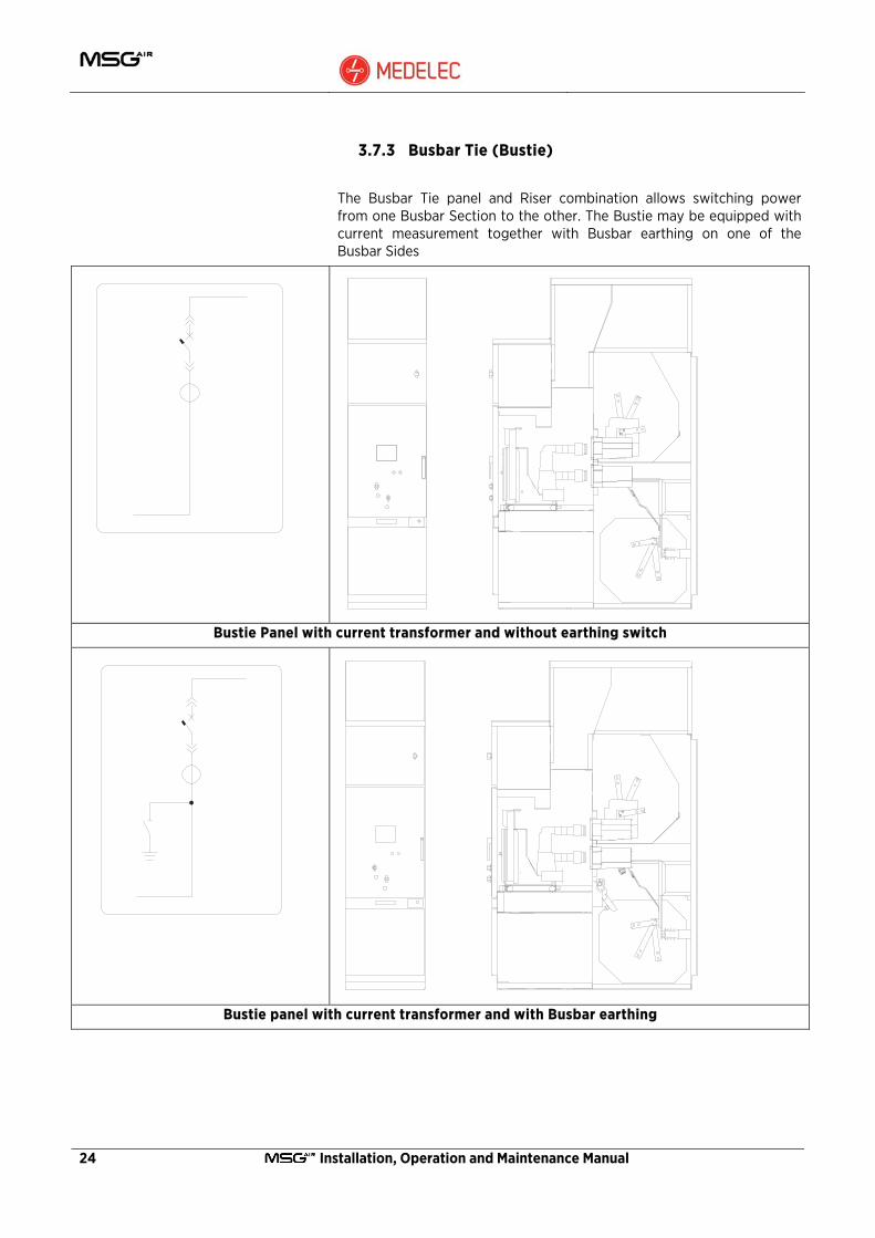
3.7.3 Busbar Tie (Bustie)
The Busbar Tie panel and Riser combination allows switching power from one Busbar Section to the other. The Bustie may be equipped with current measurement together with Busbar earthing on one of the Busbar Sides
Bustie Panel with current transformer and without earthing switch
Bustie panel with current transformer and with Busbar earthing

Installation, Operation and Maintenance Manual 25
Bustie panel without CT and without earthing switch
Bus tie without CT but with Busbar earthing

26 Installation, Operation and Maintenance Manual
3.7.4 Busbar riser
The Busbar Riser panel in combination with the Bustie allows the transfer of power from one Busbar Section to the other. It may be equipped with voltage measurement. The voltage transformer can be either of the fixed type (standard) or of the withdrawable type complete with HV fuses (optional).
Busbar riser with fixed measuring VT
Busbar Riser with withdrawable measuring VT c/w HV fuses

Installation, Operation and Maintenance Manual 27
3.7.5 Measurement panel (Client-specific optional)
A measurement panel allows for voltage measurement together with earthing on one of the Busbar sections. The voltage transformer can be either of the fixed type (standard) or of the withdrawable type complete with HV fuses (optional).
Measurement panel with Fixed VT and earthing switch.
Measurement panel with withdrawable VT and earthing switch.
28 Installation, Operation and Maintenance Manual
4 Interlocks To prevent hazardous situations and erroneous operation, switchgear is equipped with a series of interlocks to protect both personnel and equipment.
WARNING: Interlocks must only be removed by approved operators and only if absolutely necessary for operational reasons. When removing an interlock, the operator must take special and adequate safety measures to prevent situations, which might have fatal consequences.
Warning: It is important that where covers are supplied with screws, such as cable compartment covers and busbar covers they must be removed only when the circuit is dead and earthed.
Before removing such covers make sure that the power cable and all busbars are dead and earthing switch is ON for the safety of the personnel.
Only energise the unit once all the removed covers have been re-assembled back on the panel.
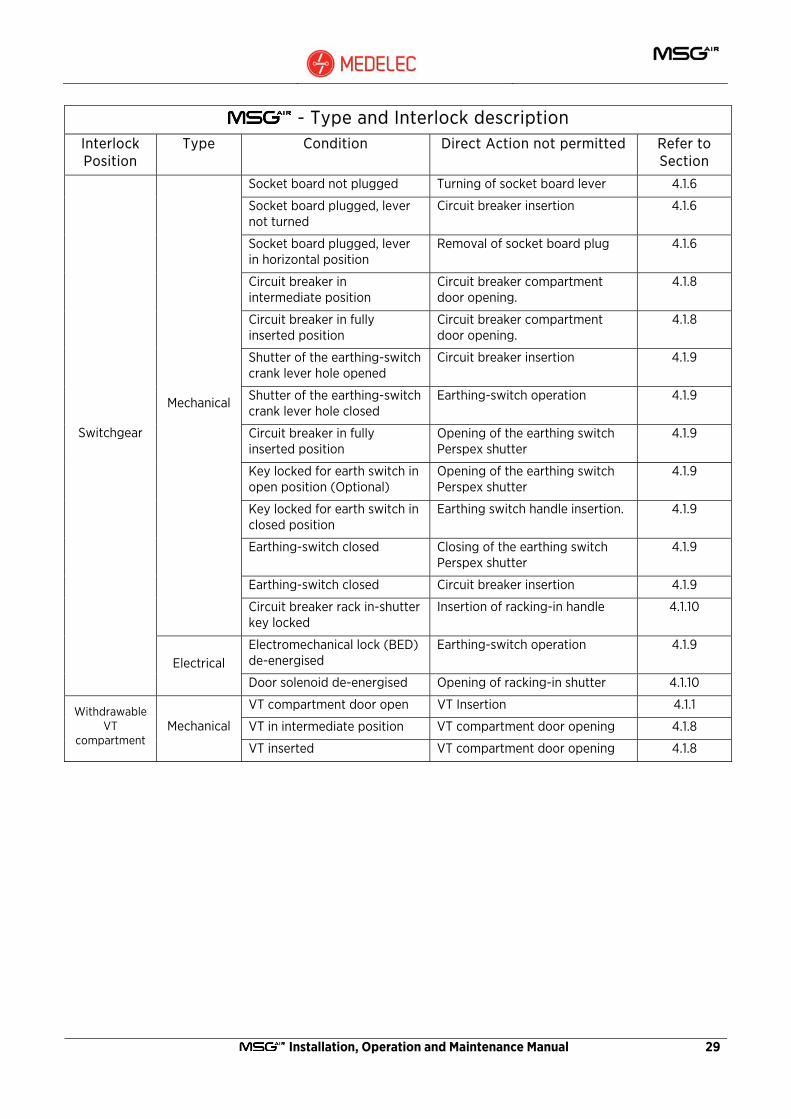
4.1 Interlock Cross reference table
The following table gives a summary of the interlocks, both mechanical and electrical, supplied as standard with the switchgear.
- Type and Interlock description Interlock Position
Type Condition Direct Action not permitted Refer to Section
Circuit breaker compartment door opened
Circuit breaker insertion 4.1.1
Circuit breaker closed in isolated position
Circuit breaker insertion 4.1.2
Circuit breaker closed in service position
Circuit breaker extraction 4.1.2
Circuit breaker in intermediate position
Circuit breaker closing 4.1.3
Key locked in circuit breaker open position
Circuit breaker closing 4.1.4
Circuit breaker Mechanical
Circuit breaker locking handles not fully extended.
Circuit breaker insertion 4.1.5
Installation, Operation and Maintenance Manual 29
- Type and Interlock description Interlock Position
Type Condition Direct Action not permitted Refer to Section
Socket board not plugged Turning of socket board lever 4.1.6
Socket board plugged, lever not turned
Circuit breaker insertion 4.1.6
Socket board plugged, lever in horizontal position
Removal of socket board plug 4.1.6
Circuit breaker in intermediate position
Circuit breaker compartment door opening.
4.1.8
Circuit breaker in fully inserted position
Circuit breaker compartment door opening.
4.1.8
Shutter of the earthing-switch crank lever hole opened
Circuit breaker insertion 4.1.9
Shutter of the earthing-switch crank lever hole closed
Earthing-switch operation 4.1.9
Circuit breaker in fully inserted position
Opening of the earthing switch Perspex shutter
4.1.9
Key locked for earth switch in open position (Optional)
Opening of the earthing switch Perspex shutter
4.1.9
Key locked for earth switch in closed position
Earthing switch handle insertion. 4.1.9
Earthing-switch closed Closing of the earthing switch Perspex shutter
4.1.9
Earthing-switch closed Circuit breaker insertion 4.1.9
Mechanical
Circuit breaker rack in-shutter key locked
Insertion of racking-in handle 4.1.10
Electromechanical lock (BED) de-energised
Earthing-switch operation 4.1.9
Switchgear
Electrical Door solenoid de-energised Opening of racking-in shutter 4.1.10
VT compartment door open VT Insertion 4.1.1
VT in intermediate position VT compartment door opening 4.1.8 Withdrawable
VT compartment
Mechanical
VT inserted VT compartment door opening 4.1.8

30 Installation, Operation and Maintenance Manual
4.1.1 Withdrawable equipment – racking with door open interlock
This interlock is located on the front of the withdrawable truck and interlocks with the withdrawable part racking drive mechanism. With the door open, this interlock prevents racking operations of the withdrawable part.
4.1.2 Circuit breaker – racking interlock
This interlock is located inside the circuit breaker truck and interlocks the breaker switch position with the withdrawable part racking mechanism. With the circuit breaker ON, this interlock prevents racking operations of the withdrawable part.
4.1.3 Circuit breaker – CLOSE interlock
This interlock is located inside the circuit breaker truck and interlocks the breaker switch position with the withdrawable part racking mechanism. With the circuit breaker in the intermediate position, this interlock prevents switching ON of the circuit breaker.

Installation, Operation and Maintenance Manual 31
4.1.4 Circuit breaker – CLOSE lock
The circuit breaker is equipped with a key lock to lock the breaker in the OFF position.
To lock the breaker in this position, press the OFF button on the circuit breaker whilst turning the key lock on the circuit breaker front panel shown in the adjacent photo.
4.1.5 Withdrawable equipment - latching handles
The handles on the withdrawable equipment truck are interlocked with the racking mechanism of the withdrawable equipment. If the equipment is not properly latched to the panel guides, and the handles are not fully extended, racking is prevented. On the other hand, if the withdrawable equipment is not in the fully isolated/test position, unlatching of the handles is not possible.
32 Installation, Operation and Maintenance Manual
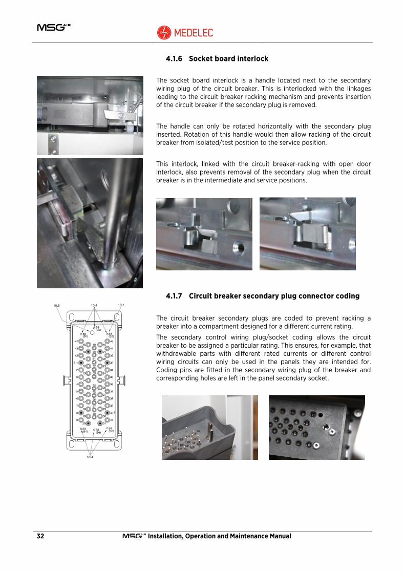
4.1.6 Socket board interlock
The socket board interlock is a handle located next to the secondary wiring plug of the circuit breaker. This is interlocked with the linkages leading to the circuit breaker racking mechanism and prevents insertion of the circuit breaker if the secondary plug is removed.
The handle can only be rotated horizontally with the secondary plug inserted. Rotation of this handle would then allow racking of the circuit breaker from isolated/test position to the service position.
This interlock, linked with the circuit breaker-racking with open door interlock, also prevents removal of the secondary plug when the circuit breaker is in the intermediate and service positions.
4.1.7 Circuit breaker secondary plug connector coding
The circuit breaker secondary plugs are coded to prevent racking a breaker into a compartment designed for a different current rating.
The secondary control wiring plug/socket coding allows the circuit breaker to be assigned a particular rating. This ensures, for example, that withdrawable parts with different rated currents or different control wiring circuits can only be used in the panels they are intended for. Coding pins are fitted in the secondary wiring plug of the breaker and corresponding holes are left in the panel secondary socket.

Installation, Operation and Maintenance Manual 33
1250A 630A
Panel Panel
4.1.7.1 Panel plug coding
Circuit Breaker socket pin coding
(B1) (B2) (B3) (B4) (B5)
630A O O
1250A O
2000A O
Panel hole pin coding
B1 B2 B3 B4 B5
630A O O
1250A O
2000A O
4.1.8 Withdrawable equipment – door interlock
This interlock is located on the right side of the withdrawable equipment compartment.
This interlock is directly coupled to the compartment shutter. It prevents the compartment door opening if the withdrawable equipment is either in the intermediate or service position. Compartment door can only be opened if the equipment is in the isolated/test position.

34 Installation, Operation and Maintenance Manual
CB moved from isolated/test position to service position - earthing switch OFF and shutter closed
CB in isolated/test position - earthing switch OFF and shutter open
4.1.9 Earthing switch interlocks
The earthing switch interlocks are located on the earthing switch fascia and mechanism.
With the earthing switch in the OFF position and the front shutter closed, circuit breaker racking from the isolated/test position to the service position is possible.
If the earthing switch is in the ON position, closing of the front shutter is not possible.
If the front shutter is not closed, the circuit breaker racking is not possible.
The front shutter can only be opened with the circuit breaker in the isolate/test position.
The earthing switch can only be operated when:
1. The unit is in the isolated/test position or completely removed. 2. The earthing switch electromechanical interlock is energized.
The earthing switch can be key-locked in the closed position. Optionally another keylock may be requested to lock the earthing switch in the open position.
When used on the Bustie and measurement panels, the busbar earthing switch (optional) can only be closed when all the withdrawable parts in the relative busbar section are either removed or in the isolated/test position. Only in this configuration can the earthing switch electromechanical interlock BED solenoid on the bustie or measurement panel be de-activated (i.e energised).
When used on incoming feeder units, this electromechanical interlock is activated when the remote feeder is switched ON. This will prevent operation of the earthing switch (See section 7.12).
De-energising the remote feeder supply will de-activate (energise) the interlock which would allow operation of the earthing switch.

Installation, Operation and Maintenance Manual 35
4.1.10 Door Interlocks
The circuit breaker compartment door contains a number of interlocks or padlocks which prevent unsafe operations.
Access to the circuit breaker racking hole can be restricted with a key lock. This prevents opening of the racking mechanism shutter thus preventing circuit breaker racking.
For substations with busbar earthing, when the busbar earthing switch is closed, the racking access shutter to the breaker compartments in the earthed busbar section is blocked. This is achieved by a solenoid located at the back of the compartment door. With this interlock activated (solenoid de-energised) the shutter cannot be opened and the circuit breakers cannot be racked in from the isolated/test position to the service position.
This electro-mechanical lock is also activated (de-energised) when DC supply and panel protection is switched off.
The racking mechanism shutter also contains a micro switch which is connected in series with the circuit breaker electrical CLOSE circuit.
CAUTION: Ensure that the shutter on the racking drive access hole is in the completely closed position. If the shutter is open, this indicates that the racking handle is in the inserted position thus preventing circuit breaker electrical closing.
The mechanical CLOSE and OPEN access guide holes on the circuit breaker compartment door can also be padlocked to prevent mechanical operation of the circuit breaker.

36 Installation, Operation and Maintenance Manual
4.1.10.1 Door rack-in shutter Interlock defeat mechanism
WARNING: Only skilled personnel with suitable knowledge of the circuit breaker and installation must carry out this operation.
WARNING: Operation must only be carried out in case of emergency since personnel safety cannot be guaranteed.
In the case when the circuit breaker has to be moved from the service position to the isolated/test position or vice versa, with the solenoid interlocking the racking shutter activated (de-energised), the following procedure has to be followed:
1. Remove the screw located besides the access hole. 2. Insert the long end of the tool used to remove the screw and
lightly push the solenoid whilst rotating the shutter until the latter hits the tool.
3. Slowly retract the tool and continue rotating the shutter until the racking drive hole is fully exposed.
NOTE: The interlock will reset itself when the shutter is released.
Installation, Operation and Maintenance Manual 37
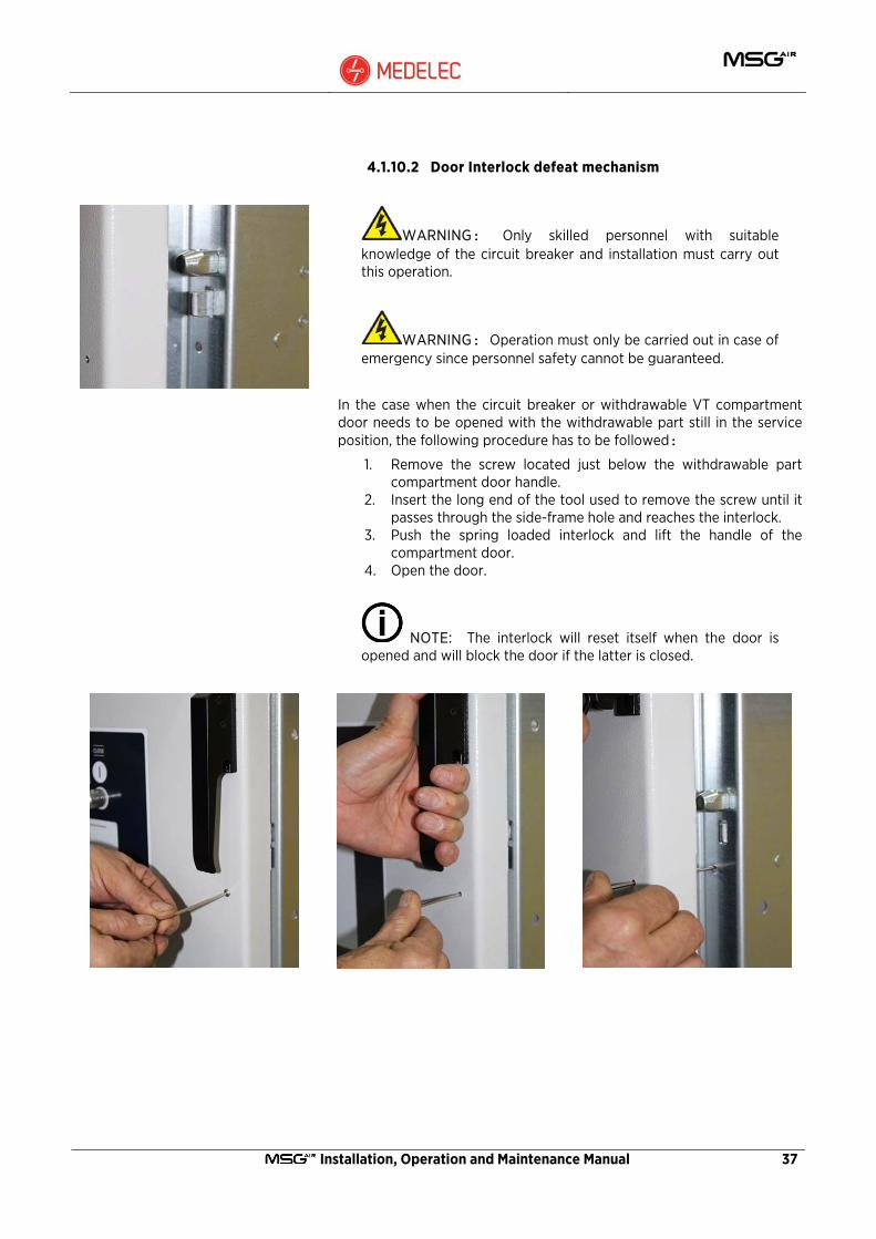
4.1.10.2 Door Interlock defeat mechanism
WARNING: Only skilled personnel with suitable knowledge of the circuit breaker and installation must carry out this operation.
WARNING: Operation must only be carried out in case of emergency since personnel safety cannot be guaranteed.
In the case when the circuit breaker or withdrawable VT compartment door needs to be opened with the withdrawable part still in the service position, the following procedure has to be followed:
1. Remove the screw located just below the withdrawable part compartment door handle.
2. Insert the long end of the tool used to remove the screw until it passes through the side-frame hole and reaches the interlock.
3. Push the spring loaded interlock and lift the handle of the compartment door.
4. Open the door.
NOTE: The interlock will reset itself when the door is opened and will block the door if the latter is closed.

38 Installation, Operation and Maintenance Manual
5 Packing Transport and Storage
5.1 Condition on delivery
At the time of dispatch, the panels are factory-assembled, the withdrawable parts are in the isolated/test position and the doors are closed.
The factory-assembled panels are checked at the factory for completeness in terms of the order and simultaneously subjected to routine testing (normally without AC voltage testing of the busbars) according to IEC publication 62271-200, and are therefore tested for correct structure and function.
The busbars are not assembled. The busbar material, fasteners and accessories are packed separately with the loose gear.
5.2 Packing
For reasons of containerised shipping and ease of installation, the units are packed separately inside crates with up to three panels per crate. The exhaust gas Compartment is sent as loose gear with each substation.
No special devices, other than those provided, are required, as assembly is carried out by aligning all the relevant sections.
The switchboards are usually shipped complete with circuit breakers, voltage transformers fitted into the relevant compartments, except when otherwise agreed. The circuit breaker and VT withdrawable truck are packed inside the respective panel and positioned in the isolated/test position.
Each switchboard section is packed in preparation for containerised shipping.
Each group is protected by an aluminium sheet which is heat sealed. The bags are vacuumed and desiccant bags placed inside each bag.
Each panel group is placed on a wooden pallet and a wooden crate surrounds the group. This crate serves to protect the panels during transportation and also to provide lashing points.

Installation, Operation and Maintenance Manual 39
5.3 Transport
Follow the symbols and instructions shown on the packaging carefully.
Transport the panels upright. Take the high centre of gravity into account. Only carry out loading operations when it has been ensured that all precautionary measures to protect personnel and materials have been taken.
The wooden crate must be fixed to the vehicle by means of ropes so as to avoid any violent impact or turning over in case of sharp turns or sudden stops. Moreover, the vehicle must be fitted with a canvas covering the whole load. The capacity load of the lifting equipment must guarantee proper weight distribution.
If the apparatus is unloaded in the warehouse or in the installation room, the access must be at least 3m high x 2.5 m wide with an area at the same level. Small differences in level can be compensated with temporary structures using wooden boards.
Unloading must be carried out with the utmost care using suitable lifting equipment for the weight of each unit group, especially in presence of energised overhead lines.
5.4 Control on receipt
On receipt, immediately check the packing and apparatus conditions.
If the panels are going to be used immediately, open the packing and check that no damage occurred during transport and make sure that the rating plate data correspond to those listed in the Substation general arrangement.
Should any damage or imperfection in the supply be noticed, report immediately to Medelec Switchgear Ltd. (directly or through the agent or the supplier) and to the carrier who delivered the goods.
Notification of any possible irregularity, even after receipt, must indicate the switchboard construction year and the relevant serial number which are shown on the switchboard rating plate.
The switchboards are only supplied complete with the accessories specified in the offer sent by Medelec Switchgear Ltd.
The documents enclosed in the packing are:
• Contract related documents, including the General Arrangement, Schematic and wiring diagrams.
• Typical drawings to assist during assembly of the switchboard. • This instruction manual.
In the case that the units will not be used immediately on receipt, follow the procedure listed in 5.5 below.

40 Installation, Operation and Maintenance Manual
5.5 Intermediate storage
Optimum intermediate storage, where this is necessary, without any negative consequences depends on compliance with a number of minimum conditions for the panels and assembly materials.
Store the panels upright and do not stack panels. Store the units protected from the weather in a dry, dust-free, non-corrosive place and safe from any damage.
Check the packing for damage and regularly check for any condensation until installation is started. If any damage to the packing is noticed, carefully open the packing and inspect the units for signs of transportation damage or water ingress.
In case of damage observe procedure as detailed in 5.4 above. If no damage is noticed, replace the drying agents and re-seal the aluminium bags.
When the maximum storage period is too long the protective function of the packing can no longer be guaranteed and suitable action must be taken if intermediate storage is to continue. The packaging contains dehydrating bags that must be replaced every six months.
In particular instances of very long storage, it is advisable to store the units in an indoor space. It is also advisable to connect the anti-condensation heater whenever this is supplied on the switchgear.
5.6 Handling
5.6.1 Handling the Switchgear
Switchgear units are packed on wooden pallets surrounded by a wooden crate. The panel groups must be handled by means of a crane or fork lift truck.
When using a crane, use a circular sling which must be inserted according to the lifting symbols marked on the crate.
Weight and lifting opening angle must be taken into account when choosing the circular slings.
Installation, Operation and Maintenance Manual 41
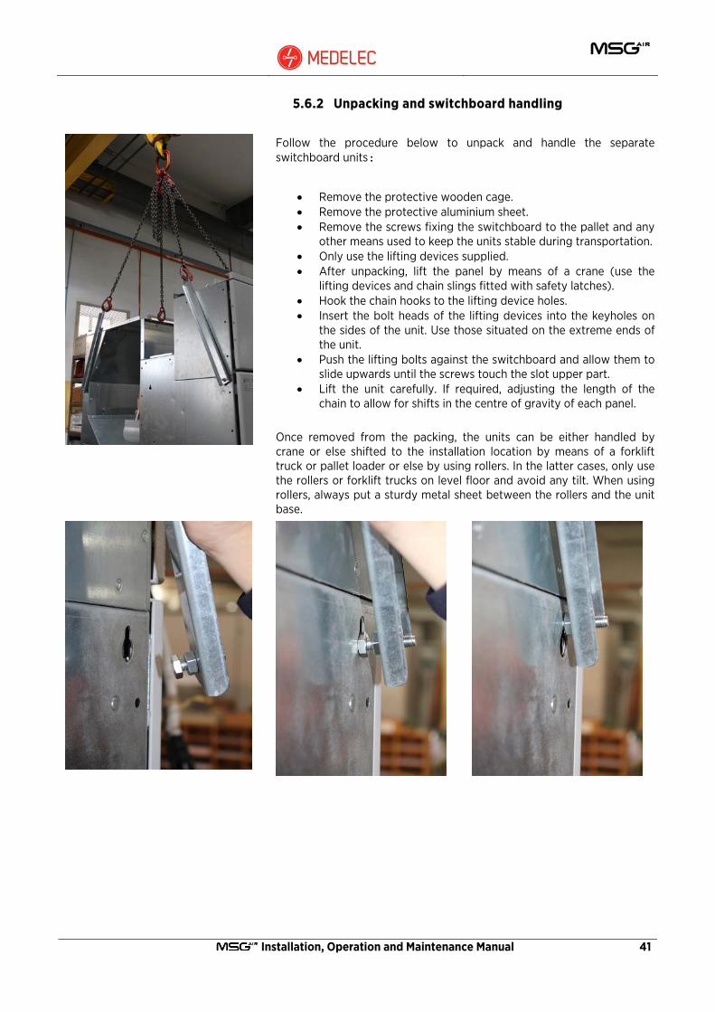
5.6.2 Unpacking and switchboard handling
Follow the procedure below to unpack and handle the separate switchboard units:
• Remove the protective wooden cage. • Remove the protective aluminium sheet. • Remove the screws fixing the switchboard to the pallet and any
other means used to keep the units stable during transportation. • Only use the lifting devices supplied. • After unpacking, lift the panel by means of a crane (use the
lifting devices and chain slings fitted with safety latches). • Hook the chain hooks to the lifting device holes. • Insert the bolt heads of the lifting devices into the keyholes on
the sides of the unit. Use those situated on the extreme ends of the unit.
• Push the lifting bolts against the switchboard and allow them to slide upwards until the screws touch the slot upper part.
• Lift the unit carefully. If required, adjusting the length of the chain to allow for shifts in the centre of gravity of each panel.
Once removed from the packing, the units can be either handled by crane or else shifted to the installation location by means of a forklift truck or pallet loader or else by using rollers. In the latter cases, only use the rollers or forklift trucks on level floor and avoid any tilt. When using rollers, always put a sturdy metal sheet between the rollers and the unit base.

42 Installation, Operation and Maintenance Manual
5.6.3 Handling the removable parts
The removable Components can be handled by means of cranes, fork lift trucks or using the trolley provided with the switchgear.
For each component follow the instructions below.
CAUTION: Before handling the apparatus, make sure that the operating mechanism springs are discharged and that the apparatus is in the open position.
NOTE: While handling, do not put any stress on the insulating parts and on the apparatus terminals.
When handling by crane, hook the lifting device to the relevant supports.
When handling by means of a forklift truck, do not insert the truck forks straight underneath the removable components but put the components on a sturdy support.
For handling and inserting the apparatus into the switchboard, use the trolley supplied by Medelec.
In order to shift the circuit breaker to the relevant trolley, follow the instructions below:
• Hook the lifting devices to the circuit breaker supports and align it above the trolley.
• Press the handles towards the circuit breaker centre to make the horizontal check pins go in.
• Put the circuit breaker on the trolley. • Push the circuit breaker towards the back of the trolley until the
handles are released outwards and the horizontal locking pins go into the slots, locking the circuit breaker.
The same procedure applies to the withdrawable VT truck.
NOTE: When lowering the withdrawable part ensure that the truck interlock does not foul the operation.
NOTE: The lifting devices provided on the circuit breaker must be removed before the unit is put in operation.

Installation, Operation and Maintenance Manual 43
6 Installation 6.1 Installation - General Information
Correct installation is of paramount importance. The instructions given in this manual must be thoroughly studied and followed.
Installation must be carried out either by Medelec personnel or by suitably qualified and skilled customer personnel trained by Medelec with in-depth knowledge of the apparatus.
It is advisable to wear gloves for handling the components.
Before removing the circuit breaker panel cover make sure that the circuit breaker is open and the closing springs discharged.
Do not walk over the switchboard when it is energized.
The switchboard room must be dry, clean and complete with all the necessary fixtures and fittings (cable duct, gas outlets etc.).
The following limit values, among others, apply:
Ambient temperature: Maximum +40 °C Maximum 24 h average +35 °C Minimum -5 °C
The maximum site altitude is 1000 m above sea level.
Details Dimension (mm)
A 100
Free standing unit 800
B
Wall mounted unit 100
C 1500
D With gas duct 2710

44 Installation, Operation and Maintenance Manual
6.2 Foundation and switchgear erection
After the order acknowledgement, Medelec Switchgear will supply the customer with the switchboard foundation and fixing drawings to prepare the installation room. The floor or the foundation must be strong enough to bear the weight of the switchboard (plus all the circuit breakers) without any deformation.
6.2.1 Tightening torque table
The table below gives the torque values for fixing and coupling switchboards and busbars.
CAUTION: Do not grease the screws or nuts.
Screw Type: 8.8G Tightening Torque
(Nm)
M6 9.0
M8 22
M10 45
M12 75
M16 185
M18 260
M20 250
Tolerance: -0% to +20% 6.2.2 Foundation details
Correct operation of the Switchgear is dependent on it being level. It is essential, therefore, that care is taken at all stages of erection, in particular the alignment and levelling of the first unit, which will be the datum for all other units. Failure to erect the first unit correctly will result in misalignment throughout the switchboard. Foundation fixings may be of the unistrut foundation channel type (See Section 6.2.3) or of the foundation bolt type, expanding type (See Section 6.2.4)

Installation, Operation and Maintenance Manual 45
Dimension (mm)
Unit Type Unit Rating A B C D E F G H I
Feeder, Bustie, Riser, Measurement
Panel.
630..1250A 600 1470 72 455 95 850 345 450 200
Feeder, Bustie, Riser.
2000A 750 1470 72 605 95 850 345 600 200

46 Installation, Operation and Maintenance Manual
6.2.3 Fixing with unistruts foundation Channels
The unistruts foundation channels, which can be supplied on request, must be installed in the floor concrete slab before finishing the floor. Prepare the floor and foundations taking into consideration the location of the cable trench.
Rest the unistruts in the appropriate cavities in the floor and line them up so that they are parallel and are spaced from each other as shown in the foundation drawing. Level the channels both longitudinally and transversally using the straps and cross braces supplied. Fix the unistruts in this position with concrete. Complete the flooring so that the surface of the unistruts extend out at least 0.5 mm from the finished floor surface.

Installation, Operation and Maintenance Manual 47
6.2.4 Fixing with anchoring bolts (Expanding type bolts)
The round holes in the base of the housing can be used as a template to drill the floor for accepting M12 x 75mm long expanding bolts. After drilling, clean the installation area. On the floor, visibly trace the perimeter of all the cubicles making up the switchboard, taking the minimum wall and obstacle clearances, and location of main cable trenches into account. If necessary level the floor both longitudinally and transversally.
Proceed with the installation of the panels as described in section 6.2.5 below. Instead of the anchor nuts, insert the expansion anchoring bolts in the holes and fix the panel to the floor with M12 bolts. Apply a standard torque of 70Nm.
6.2.5 Position and fixing the units on the foundation
CAUTION: It is advisable to leave the circuit breakers, and voltage transformer trucks (where possible) inside the panel until the panels are fixed to the floor:
NOTE: To guarantee correct alignment of the different sections it is advisable to draw a line parallel to the switchboard front and keep a constant distance from this line while positioning and fixing the units.
The various units must be fixed to the channels ideally starting either from the central section or from the highest point on the unistrut channels, and then proceeding to the side cubicles. This starting point then becomes the datum for all units. Although it is ideal to use this point for erection of the first unit, installation can also be started from the extreme units if the layout does not permit otherwise.
With reference to the general arrangement drawing of the switchboard, check the unit serial numbers for correct sequence of erection.
To position the units lift the unit with the appropriate lifting attachments and place it on the foundation layout.
Locate the foundation holes and insert the anchoring nuts (in the case when unistrut foundations have been laid) through the rectangular openings and fix the unit with the supplied screws through the appropriate round holes adjacent to the rectangular cut-outs. Fit the fixing bolts and associated washers through the holes in the base of the housing into the spring loaded nuts within the channels. DO NOT TIGHTEN for the time being. Using 2 plumb lines level the housing front to back and across the width. Levelling is carried out using the shim plates provided. These shims shall be located adjacent to and on the outside of the foundation bolts such that they will also support the adjacent housing when erected.
48 Installation, Operation and Maintenance Manual
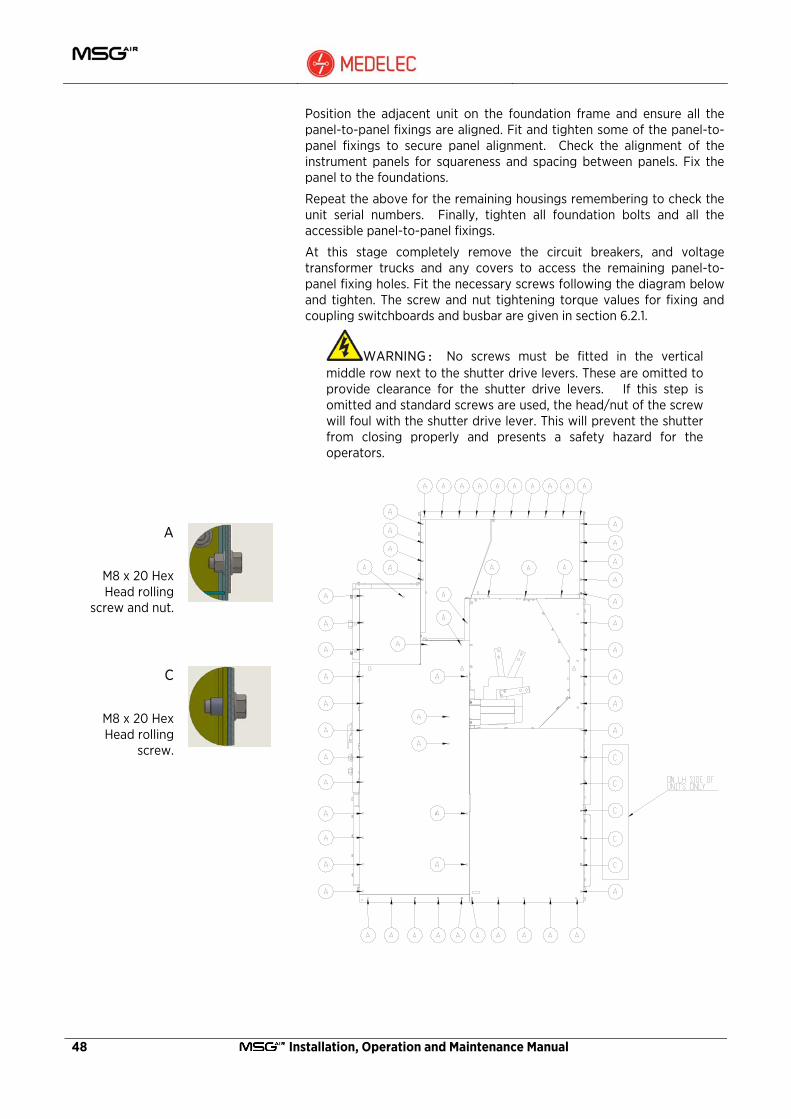
Position the adjacent unit on the foundation frame and ensure all the panel-to-panel fixings are aligned. Fit and tighten some of the panel-to-panel fixings to secure panel alignment. Check the alignment of the instrument panels for squareness and spacing between panels. Fix the panel to the foundations.
Repeat the above for the remaining housings remembering to check the unit serial numbers. Finally, tighten all foundation bolts and all the accessible panel-to-panel fixings.
At this stage completely remove the circuit breakers, and voltage transformer trucks and any covers to access the remaining panel-to-panel fixing holes. Fit the necessary screws following the diagram below and tighten. The screw and nut tightening torque values for fixing and coupling switchboards and busbar are given in section 6.2.1.
WARNING: No screws must be fitted in the vertical middle row next to the shutter drive levers. These are omitted to provide clearance for the shutter drive levers. If this step is omitted and standard screws are used, the head/nut of the screw will foul with the shutter drive lever. This will prevent the shutter from closing properly and presents a safety hazard for the operators.
A
M8 x 20 Hex Head rolling
screw and nut.
C
M8 x 20 Hex Head rolling
screw.

Installation, Operation and Maintenance Manual 49
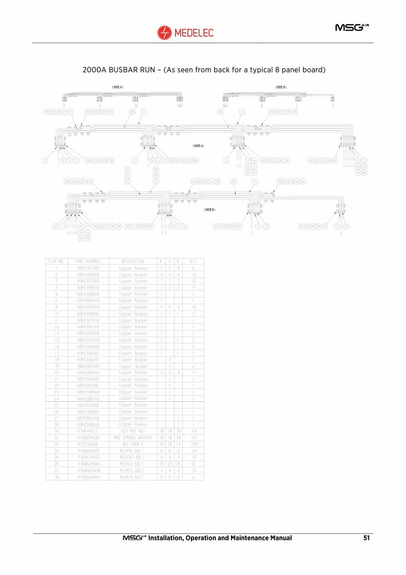
6.3 Main Busbar Assembly
NOTE: The connections are made either of bare copper or of silver-plated copper. Make sure that the connection contact surfaces are perfectly flat, without any burrs, oxidation traces or deformations.
The inter unit busbars are coupled by means of standard tools. All the necessary coupling bus bars are supplied with the equipment.
Access to the busbar compartment for making the busbar joints is via removable covers at the back of the unit.
In the case of wall mounted panels, access to the busbar Compartment is via the top of the unit prior to fitting the gas Compartment. This is achieved by removing the filter mesh panels.
Before assembly, thoroughly clean the busbar contact area using a clean cloth with alcohol or a suitable solvent to ensure a good contact surface. Plated contact surfaces shall be cleaned using a branded liquid silver polish. After cleaning, all surfaces shall be wiped with a clean cloth to remove any metal dust, etc. Joints shall be assembled as soon as possible after preparation.
The same treatment of contact surfaces shall be carried out on all other joints, such as the tee-off to voltage transformers and main cable connections. For assembly of busbars refer to busbar layout drawings supplied with loose gear.
Hold the busbars in position as shown in the drawing for busbar joints.
Fix in place with bolts, washers and nuts as shown in the illustration.
For the time being tighten the bolts by hand only (use no tools) until all the busbars are aligned.
After alignment tighten the screw and nut to torque values as given in the table of Section 6.2.1

50 Installation, Operation and Maintenance Manual
1250A BUSBAR RUN – (As seen from back for a typical 8 panel board)
Installation, Operation and Maintenance Manual 51
2000A BUSBAR RUN – (As seen from back for a typical 8 panel board)

52 Installation, Operation and Maintenance Manual
Riser panel busbar arrangement

Installation, Operation and Maintenance Manual 53
6.4 Unit earthing
The main earth bars of the units are preassembled within the unit. The only assembly required on site is, to connect the earth bars of adjacent units together using the interconnecting earth bar supplied with the unit. Make sure that the contact surfaces of the earthing busbar connections are perfectly flat, without any burrs, oxidation traces or deformations.
The earth bar must be terminated to the station earth system via the connection to the end unit earth protruding from the decorative end covers.
NOTE: The extreme unit earth bar for connection to the substation earth is supplied as loosegear.

54 Installation, Operation and Maintenance Manual
6.5 Installation of Gas Compartment
The installation room must be prepared according to the switchboard size and type and in line with the drawings supplied by Medelec Switchgear ltd.
Compliance with the dimensions guarantees correct operation of the apparatus.
To allow for containerised shipments, the gas Compartment is flat packed and sent as loose material.
Assemble the gas Compartment for each unit starting from the central units and moving out.
• Assemble the front and rear covers. Ensure that the front and back supports are vertically aligned with the sides of the switchboard panel before tightening the screws.
• Install the top cover and fit the screws without tightening. • Assemble the middle partition and tighten the screws. • Install the two adjacent gas Compartments by repeating the
above steps. • Check the horizontal alignment of the three units and tighten
the screws holding the top covers together and also those holding the top cover to the vertical supports.
• Continue assembly of the remaining gas Compartments as described above.
• Assemble the gas Compartment end covers according to the agreed configuration.
• Finally assemble the decorative covers on the rear and front of the gas Compartment.
• Finally fit the gas duct (not within Medelec scope of supply) to channel gases generated by an internal arc fault out of the substation building.

Installation, Operation and Maintenance Manual 55

56 Installation, Operation and Maintenance Manual
6.6 The gas duct
NOTE: All the necessary ducting to route the Internal Arc gases safely out of the substation are outside the scope of supply of Medelec switchgear Ltd. Detailed drawings of the duct cross section and fixing holes location can be provided.
To guarantee safe operation, the duct extensions must be manufactured from galvanised sheet metal at least 2mm thick and manufactured according to the drawings provided by Medelec Switchgear Ltd.
In the case where bends cannot be avoided, these are to be constructed using the maximum radius possible. Each 1 meter section can be pre-assembled and then joined to the switchgear. Fit the units using the appropriate screws and tighten as per values given in Section 6.2.1. Once outside the switchgear room, the end has to be protected from water ingress and foreign objects. The duct outlet area must be adequately chosen to avoid risk of injury and damage to third party property. Adequate signs must also be placed at the duct exit.

Installation, Operation and Maintenance Manual 57
6.7 Connection of Inter-unit auxiliary wiring (Bus-wiring)
The only secondary wiring required on site is to run and terminate the inter-unit bus-wires in accordance with the wiring diagrams supplied. Auxiliary wiring for inter-panel connection is run from panel-to-panel through the dedicated auxiliary wiring duct on top of the Low Voltage Compartment.
Remove the auxiliary wiring duct cover and route the cables accordingly. For ease of connection, each wire is fitted with an identification ferrule, which corresponds with the markings on the terminal block. Open the doors of the low voltage compartment and terminate the wire ends in accordance with the bus wire diagram. Replace the duct cover once all wiring has been completed.
The loosegear contains a detailed wiring diagram for the secondary wiring and the inter-panel wiring (Bus wires).
6.8 Connecting the auxiliary multicore cables
Multicore cables can be routed either from the front bottom cutouts, from the rear bottom cutout or through the auxiliary wiring trough situated on top of the low voltage cubicle together with the bus wires.
6.8.1 Front bottom entry
Whenever auxiliary wiring is routed through a separate trench from the power cables, this must be located just behind the front switchgear fixing locations and underneath the auxiliary wiring entry cutouts.
Use the left entry cutout at the bottom front location. Remove the vertical wiring trough covers. Route the cables to the Low voltage cubicle tying them to the appropriate fixings to take the weight of the cable. Fit the wiring to the vertical terminal strip on the Left hand side of the Low voltage cubicle following the wiring diagrams supplied. Fit the wiring trough covers

58 Installation, Operation and Maintenance Manual
6.8.1 Rear bottom entry
In the case when the auxiliary cables are passed through the trench together with the power cables, use the left entry cutout at the bottom rear location. Remove the left hand horizontal wiring trough covers by loosening the front fixing screws and pulling out the trough and unscrewing the rear cover. Remove the left hand vertical wiring trough covers. Route the cables to the Low voltage cubicle tying them to the appropriate fixings of the vertical run to take the weight of the cable. Fit the wiring to the vertical terminal strip on the Left hand side of the Low voltage cubicle following the wiring diagrams supplied. Fit the wiring trough covers.
6.8.2 Low voltage wiring trough
If the auxiliary cables are passed inside cable trays hanging from the ceiling of the substation, these can be routed down through the auxiliary wiring duct on top of the Low Voltage Cubicle.
Open the top cover of the low voltage wiring trough on top of the low voltage cubicle. Remove the side cover of the wiring trough on the extreme end. Prepare the necessary holes for the glands/grommets according to the cable size. Feed the auxiliary cables and lay them on the low voltage cubicle to the relevant panel.

Installation, Operation and Maintenance Manual 59
6.9 Power cable termination
Access to the main cable terminations is via removable covers at the rear of the housing or from the front of the panel (This is not advisable when a withdrawable VT is installed).
Warning: When carrying out installation or maintenance work inside the cable compartment ensure that cable is de-energised and earthed.
When rear access is possible, unscrew the bottom rear cover of the cable compartment. Access via the rear cover does not require any other disassembly. In the case where 2 sets of cables are to be terminated, start with the set towards the front of the unit and then move back.
For cable termination of wall mounted panels, access is from the front. Open the circuit breaker and VT compartment doors. Unscrew and remove the front horizontal stiffener below the circuit breaker compartment. Unscrew the clips, from this partition, holding the earth switch auxiliary wiring loom, and remove the partition. Remove the 4 screws holding the horizontal partition between the circuit breaker and VT/cable compartment.
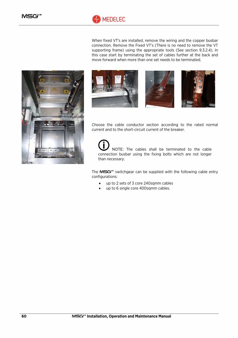
60 Installation, Operation and Maintenance Manual
When fixed VT’s are installed, remove the wiring and the copper busbar connection. Remove the Fixed VT’s (There is no need to remove the VT supporting frame) using the appropriate tools (See section 9.3.2.4). In this case start by terminating the set of cables further at the back and move forward when more than one set needs to be terminated.
Choose the cable conductor section according to the rated normal current and to the short-circuit current of the breaker.
NOTE: The cables shall be terminated to the cable connection busbar using the fixing bolts which are not longer than necessary.
The switchgear can be supplied with the following cable entry configurations:
• up to 2 sets of 3 core 240sqmm cables • up to 6 single core 400sqmm cables.

Installation, Operation and Maintenance Manual 61
6.9.1 Cable supports and grommets for single core cables
The configuration as shown in the Figure below consists of a transversally split gland plate made from 3mm aluminium fitted with rubber grommets for vermin proofing and protection of the cable insulation. In order to relief strain from the copper busbar connections, the cables are supported and secured by cable clamps located inside the cable compartment. Terminate and connect the cable in accordance with the manufacturer’s instructions.
Connect the earthing screen of the cable to the earth point provided in the cable box compartment.
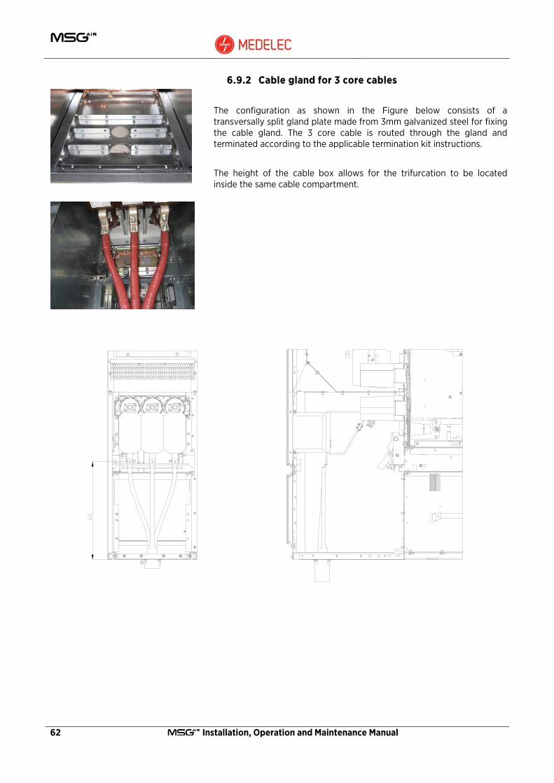
62 Installation, Operation and Maintenance Manual
6.9.2 Cable gland for 3 core cables
The configuration as shown in the Figure below consists of a transversally split gland plate made from 3mm galvanized steel for fixing the cable gland. The 3 core cable is routed through the gland and terminated according to the applicable termination kit instructions.
The height of the cable box allows for the trifurcation to be located inside the same cable compartment.

Installation, Operation and Maintenance Manual 63
6.10 Installation of the decorative end covers
The decorative end covers on the have two functions. Apart from providing an aesthetically appealing view of the switchboard, they are designed to absorb and dissipate the thermal and pressure shocks during an internal arc fault if this occurs in any one of the extreme units.
CAUTION: Proper assembly of the end covers is crucial to guarantee integrity of the panel during an internal arc fault.
Follow the assembly instructions below and refer to the drawing in the next pages for the fixing details.
• Assemble the busbar compartment end cover. • Install the front flat galvanised steel sheet and fix it in position
using the two central locations provided. • Position the rear decorative end cover and fix with few screws.

64 Installation, Operation and Maintenance Manual
• Position the front decorative cover on top of the rear cover common fixing location and fix with few screws.
• When installing the substation earth connection, open the small shutter on the bottom of the rear decorative end cover and pass the copper bar through this opening.
• Set correct alignment of both covers and install and tighten all the screws.
Warning: The vertical middle row of screws is button head screws inserted from the inside. If this step is omitted and standard screws are used, the head of the screw will foul the shutter drive lever. This will prevent the shutter from closing properly and presents a safety hazard for the operators.
• Install the end exhaust gas compartment cover and fix all the screws around the top sides and bottom.
• Install the Auxiliary wiring duct top and end covers. • Install the front and rear exhaust gas compartment decorative
covers.
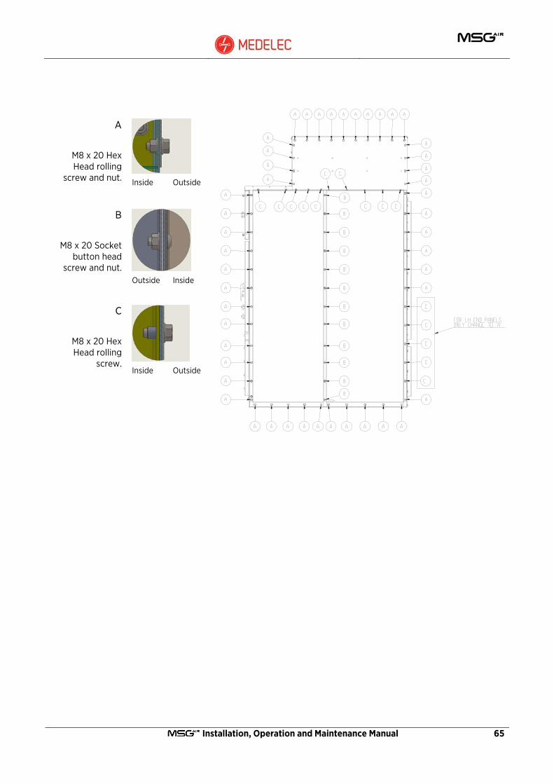
Installation, Operation and Maintenance Manual 65
A
M8 x 20 Hex Head rolling
screw and nut. Inside Outside
B
M8 x 20 Socket button head
screw and nut. Outside Inside
C
M8 x 20 Hex Head rolling
screw. Inside Outside

66 Installation, Operation and Maintenance Manual
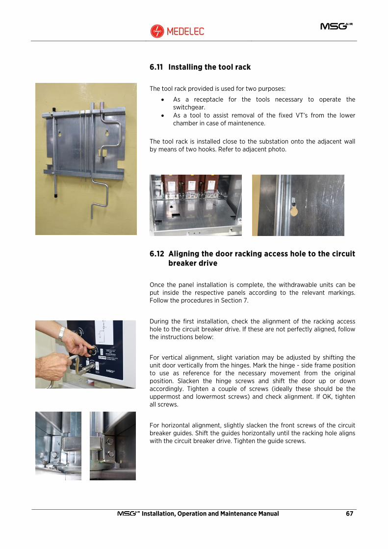
Installation, Operation and Maintenance Manual 67
6.11 Installing the tool rack
The tool rack provided is used for two purposes:
• As a receptacle for the tools necessary to operate the switchgear.
• As a tool to assist removal of the fixed VT’s from the lower chamber in case of maintenence.
The tool rack is installed close to the substation onto the adjacent wall by means of two hooks. Refer to adjacent photo.
6.12 Aligning the door racking access hole to the circuit breaker drive
Once the panel installation is complete, the withdrawable units can be put inside the respective panels according to the relevant markings. Follow the procedures in Section 7.
During the first installation, check the alignment of the racking access hole to the circuit breaker drive. If these are not perfectly aligned, follow the instructions below:
For vertical alignment, slight variation may be adjusted by shifting the unit door vertically from the hinges. Mark the hinge - side frame position to use as reference for the necessary movement from the original position. Slacken the hinge screws and shift the door up or down accordingly. Tighten a couple of screws (ideally these should be the uppermost and lowermost screws) and check alignment. If OK, tighten all screws.
For horizontal alignment, slightly slacken the front screws of the circuit breaker guides. Shift the guides horizontally until the racking hole aligns with the circuit breaker drive. Tighten the guide screws.

68 Installation, Operation and Maintenance Manual
6.13 Final check
When the installation is ready ensure that the switchboards are clean and free from any loose material such as fasteners, cable ties, loose cables, etc..
Also check that the panels have not been damaged or deformed during the installation process.
Ensure that all screws have been installed and tightened as per the recommended torque settings in section 6.2.1.
6.14 Circuit name label
The circuit breaker door of each unit has a blank label attached just above the viewing window. This serves to write or engrave the name of the particular circuit once connected and energised.
6.15 Extending the switchboard
In the case when the switchboard needs to be extended, the end covers are removed, and the last leg of the busbar run slackened. The end pieces on the busbar run are removed for subsequent use on the newly installed end unit. Follow the same procedure for unit installation as described in section 6.2. Fit the busbar as per instruction in section 6.3 using the supplied material and the busbar end piece removed previously. Install and connect the unit earthing as per Section 6.4 and complete the installation following procedures in sections 6.5 to 6.10. Carry out any necessary alterations to the substation wiring as required.
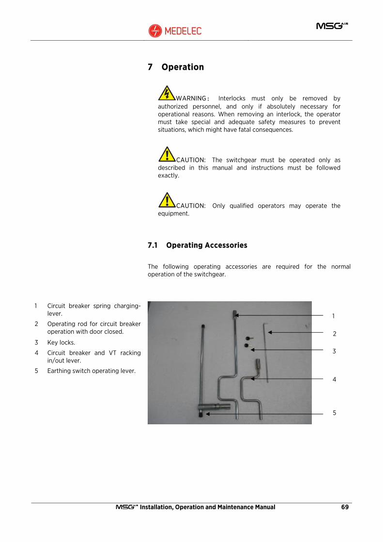
Installation, Operation and Maintenance Manual 69
7 Operation
WARNING: Interlocks must only be removed by authorized personnel, and only if absolutely necessary for operational reasons. When removing an interlock, the operator must take special and adequate safety measures to prevent situations, which might have fatal consequences.
CAUTION: The switchgear must be operated only as described in this manual and instructions must be followed exactly.
CAUTION: Only qualified operators may operate the equipment.
7.1 Operating Accessories
The following operating accessories are required for the normal operation of the switchgear.
1 Circuit breaker spring charging- lever.
2 Operating rod for circuit breaker operation with door closed.
3 Key locks.
4 Circuit breaker and VT racking in/out lever.
5 Earthing switch operating lever.
1
2
3
4
5
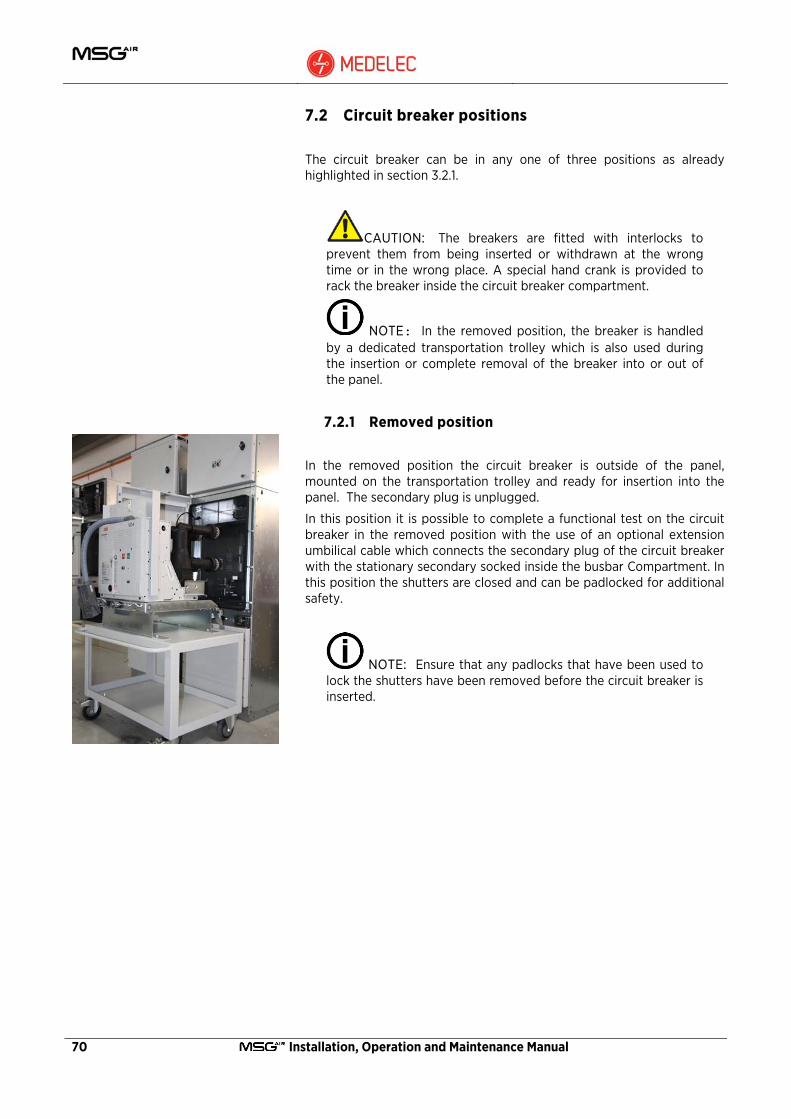
70 Installation, Operation and Maintenance Manual
7.2 Circuit breaker positions
The circuit breaker can be in any one of three positions as already highlighted in section 3.2.1.
CAUTION: The breakers are fitted with interlocks to prevent them from being inserted or withdrawn at the wrong time or in the wrong place. A special hand crank is provided to rack the breaker inside the circuit breaker compartment.
NOTE: In the removed position, the breaker is handled by a dedicated transportation trolley which is also used during the insertion or complete removal of the breaker into or out of the panel.
7.2.1 Removed position
In the removed position the circuit breaker is outside of the panel, mounted on the transportation trolley and ready for insertion into the panel. The secondary plug is unplugged.
In this position it is possible to complete a functional test on the circuit breaker in the removed position with the use of an optional extension umbilical cable which connects the secondary plug of the circuit breaker with the stationary secondary socked inside the busbar Compartment. In this position the shutters are closed and can be padlocked for additional safety.
NOTE: Ensure that any padlocks that have been used to lock the shutters have been removed before the circuit breaker is inserted.
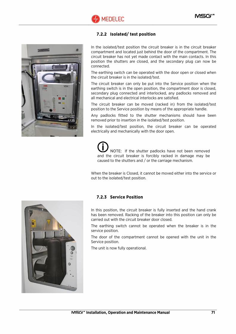
Installation, Operation and Maintenance Manual 71
7.2.2 Isolated/ test position
In the isolated/test position the circuit breaker is in the circuit breaker compartment and located just behind the door of the compartment. The circuit breaker has not yet made contact with the main contacts. In this position the shutters are closed, and the secondary plug can now be connected.
The earthing switch can be operated with the door open or closed when the circuit breaker is in the isolated/test.
The circuit breaker can only be put into the Service position when the earthing switch is in the open position, the compartment door is closed, secondary plug connected and interlocked, any padlocks removed and all mechanical and electrical interlocks are satisfied.
The circuit breaker can be moved (racked in) from the isolated/test position to the Service position by means of the appropriate handle.
Any padlocks fitted to the shutter mechanisms should have been removed prior to insertion in the isolated/test position.
In the isolated/test position, the circuit breaker can be operated electrically and mechanically with the door open.
NOTE: If the shutter padlocks have not been removed and the circuit breaker is forcibly racked in damage may be caused to the shutters and / or the carriage mechanism.
When the breaker is Closed, it cannot be moved either into the service or out to the isolated/test position.
7.2.3 Service Position
In this position, the circuit breaker is fully inserted and the hand crank has been removed. Racking of the breaker into this position can only be carried out with the circuit breaker door closed.
The earthing switch cannot be operated when the breaker is in the service position.
The door of the compartment cannot be opened with the unit in the Service position.
The unit is now fully operational.
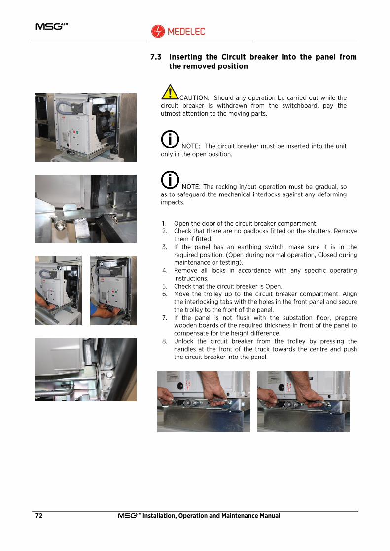
72 Installation, Operation and Maintenance Manual
7.3 Inserting the Circuit breaker into the panel from the removed position
CAUTION: Should any operation be carried out while the circuit breaker is withdrawn from the switchboard, pay the utmost attention to the moving parts.
NOTE: The circuit breaker must be inserted into the unit only in the open position.
NOTE: The racking in/out operation must be gradual, so as to safeguard the mechanical interlocks against any deforming impacts.
1. Open the door of the circuit breaker compartment. 2. Check that there are no padlocks fitted on the shutters. Remove
them if fitted. 3. If the panel has an earthing switch, make sure it is in the
required position. (Open during normal operation, Closed during maintenance or testing).
4. Remove all locks in accordance with any specific operating instructions.
5. Check that the circuit breaker is Open. 6. Move the trolley up to the circuit breaker compartment. Align
the interlocking tabs with the holes in the front panel and secure the trolley to the front of the panel.
7. If the panel is not flush with the substation floor, prepare wooden boards of the required thickness in front of the panel to compensate for the height difference.
8. Unlock the circuit breaker from the trolley by pressing the handles at the front of the truck towards the centre and push the circuit breaker into the panel.

Installation, Operation and Maintenance Manual 73
9. When the front of the circuit breaker truck is aligned with the panel guides, release the handles and move the circuit breaker until the locking pins latch. The circuit breaker is now mechanically coupled to the compartment.
10. Unlock the trolley and remove.
NOTE: If the circuit breaker handles are not properly latched, circuit breaker racking is not possible
NOTE: In this position, circuit breaker racking is not possible if the secondary plug is disconnected.
11. Insert and mount the secondary plug in the enclosure fixed
socket. Lock the secondary plug by pushing on the plastic handle.
12. Turn the secondary interlock lever clockwise. 13. The circuit breaker is now in the isolated/test position. 14. Close the compartment door in preparation for circuit breaker
racking. 15. During the first insertion, check the vertical and horizontal
alignment of the racking access hole with the circuit breaker truck drive. This is usually set during factory assembly but might require some adjustment in case of either replacement of the withdrawable part or distortion of the unit during transport or assembly. (See Section 6.12)
NOTE: The secondary plug interlock handle cannot be rotated with the plug disconnected.
NOTE: Circuit breaker racking is only possible with the secondary plug interlock handle rotated in the horizontal position.

74 Installation, Operation and Maintenance Manual
7.4 Racking the circuit breaker from the isolated/test position to the service position
CAUTION: Do not remove the circuit breaker covers. In case of need, keep at a safe distance during apparatus opening and closing operations to avoid any contact with moving parts.
NOTE: Apart from the interlocks described above, other interlocks may be present depending on the options chosen.
NOTE: It is only possible to rack the circuit breaker from isolated/test position to service position with the circuit breaker door closed.
NOTE: The operations must be carried out using normal force (not more than 260 N), only using the special tools (see section 7.1). If the operation is prevented, check that the operating sequence is correct.
1. Make sure that the secondary plug interlock lever is fully turned in the horizontal position to lock the plug.
2. Check that the circuit breaker is OFF. 3. If there is an earthing switch on the panel, ensure it is switched
OFF and the shutter on the earthing switch drive is completely closed (See Section 4.1.9).
4. Close the panel door of the compartment. 5. Turn the knob located in the centre bottom of the door
clockwise until the operating hole is exposed. (Provided that there are no interlocks or keylocks which block the insertion of the racking handle).
6. Remove any keys from the shutter knobs. 7. Fit the short hand crank handle in the drive shaft and push to
unlock the anti-racking mechanism. 8. Keep this push on the handle and rotate clockwise until the
circuit breaker is fully inserted. 9. Remove the hand crank by rotating the knob clockwise whilst
withdrawing the handle out of the circuit breaker door. 10. Release knob and ensure that the shutter returns to the fully
closed position. 11. The circuit breaker is now locked in the Service position and is
fully operational. 12. The compartment door cannot be opened.
NOTE: Ensure that the circuit breaker is in the fully racked position. If not, operation of the switch is not possible.
NOTE: Ensure that the racking handle shutter is fully closed.

Installation, Operation and Maintenance Manual 75
7.5 Withdrawal from service to isolate/test position
1. Check that the circuit breaker is OFF. 2. Turn the knob located in the centre bottom of the door
clockwise until the operating hole is exposed. (Provided that there are no interlocks or keylocks which block the insertion of the racking handle).
3. Fit the short hand crank in the drive shaft and push to unlock the anti-racking mechanism.
4. Keep this push on the handle and rotate anti-clockwise until the circuit breaker is fully withdrawn.
5. Remove the hand crank by rotating the knob clockwise whilst withdrawing the handle out of the circuit breaker door.
6. Release knob and ensure that the shutter returns to the fully closed position.
7. The circuit breaker is now in the isolated/test position and the door can be opened.
7.6 Removal of the circuit breaker from the panel
This is the reverse operation to the procedure in Section 7.3.
1. Check through the viewing window of the door that the unit is in the isolated/test position and the breaker is OFF.
2. Open the unit compartment door. 3. Release the secondary plug interlock by turning lever
anticlockwise until the handle is in a vertical position. 4. Remove the secondary plug and fit it to the breaker. 5. Place the trolley in front of the panel and ensure that the trolley
is fully locked to the front of the panel. 6. If the panel is not flush with the substation floor, prepare
wooden boards of the required thickness in front of the panel to compensate for the height difference.
7. Push the handles on the front of the circuit breaker truck towards the centre of the breaker and pull to move the unit onto the trolley.
8. Release the handles and move the truck until the locking pins latch with the trolley.
9. Unlock the trolley and remove from the switchboard. 10. If necessary fit a padlock to the automatic shutters see Chapter
7.7. 11. Close the circuit breaker door.

76 Installation, Operation and Maintenance Manual
7.7 Padlocking the shutters
It may be necessary for safety reasons to lock the shutters when the unit has been withdrawn from the panel.
To do this, the shutter mechanism can be secured with a padlock. The maximum size of the padlock hasp is 8mm diameter.
To install the padlock, proceed as follows:
1. Remove the circuit breaker from the unit by following procedure 7.6.
2. Check that the shutters are closed properly. 3. Install the padlocks in the locations shown in the photo.
7.8 Operating the circuit breaker in the isolated/test position with door open
All mechanical and electrical operations on the circuit breaker can safely be carried out with the circuit breaker in the isolated/test position, compartment door open and secondary plug connected. Refer to circuit breaker details in section 3.2.1
CAUTION: When performing mechanical operations on withdrawn circuit breakers pay the utmost attention to the moving parts.
NOTE: Should the operations be prevented, do not force the mechanical interlocks but check that the operation sequence is correct.
7.8.1 Spring charging
Spring charging can be carried out both with door open and circuit breaker in the isolated/test position or with doors closed, with the circuit breaker in the service position.
• For manual charging refer to Section 7.9.1 • For electrical charging refer to Section 7.10.1

Installation, Operation and Maintenance Manual 77
7.8.2 Circuit breaker closing
The operation can only be performed when the closing springs are fully charged and any interlocks included are satisfied.
For manual closing, push the green ON button.
The circuit breaker closes and the position indicator on the breaker indicates that the breaker is in the Closed position.
7.8.3 Circuit breaker opening
For manual opening push the red OFF button.
The unit switches OFF and the position indicator on the breaker indicates that the breaker is in the OFF position.
7.9 Operating the circuit breaker in the service position with door closed
WARNING: Opening and closing operations with the withdrawable part in the service position should only be performed with the door closed.
When the door is closed, the circuit breaker can be manually switched ON or OFF by inserting the special rod through the special guides on the front of the compartment door.
NOTE: If you are not sure whether the switch is working properly, carry out the following procedure:
• Look through the window in the door and check to see if the switch is in the service or isolated/test position.
• The switch should be fully racked in the service position. Check that spring position indicator on the switch is in the ‘spring charged’ position.
NOTE: The door cannot be opened when the switch is in the service position.
The switching operation counter for the circuit breaker automatically increases by one unit with each operating cycle.
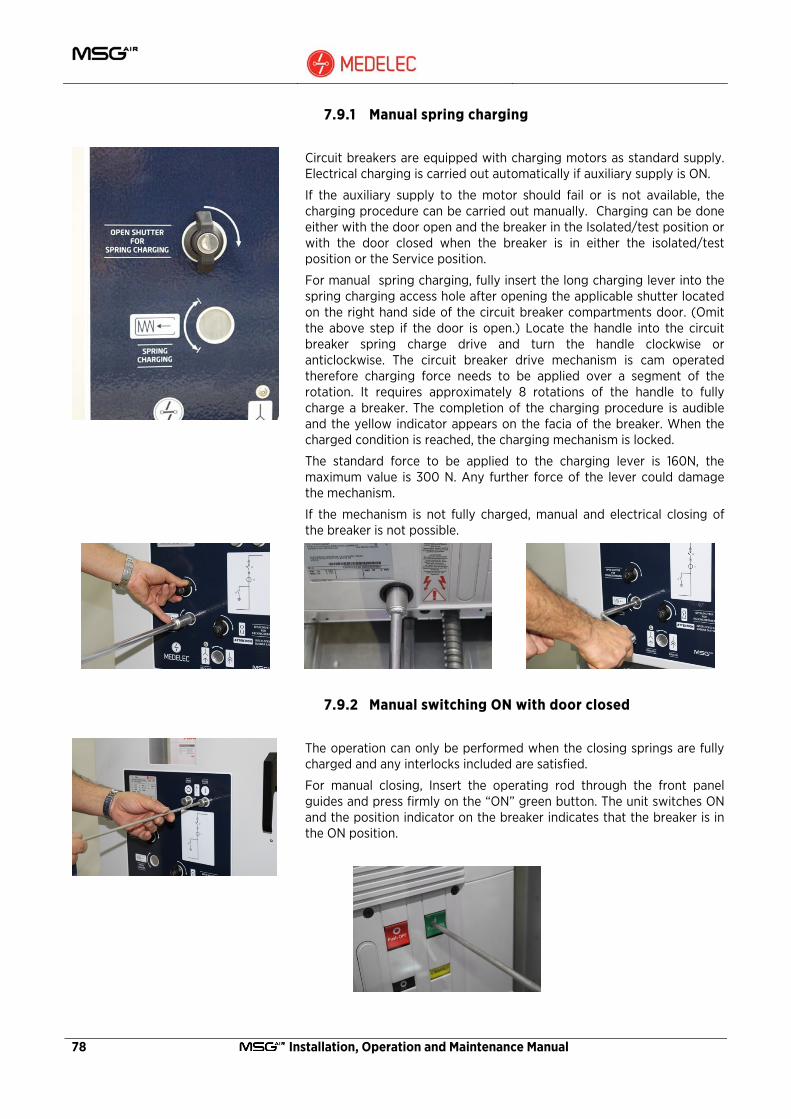
78 Installation, Operation and Maintenance Manual
7.9.1 Manual spring charging
Circuit breakers are equipped with charging motors as standard supply. Electrical charging is carried out automatically if auxiliary supply is ON.
If the auxiliary supply to the motor should fail or is not available, the charging procedure can be carried out manually. Charging can be done either with the door open and the breaker in the Isolated/test position or with the door closed when the breaker is in either the isolated/test position or the Service position.
For manual spring charging, fully insert the long charging lever into the spring charging access hole after opening the applicable shutter located on the right hand side of the circuit breaker compartments door. (Omit the above step if the door is open.) Locate the handle into the circuit breaker spring charge drive and turn the handle clockwise or anticlockwise. The circuit breaker drive mechanism is cam operated therefore charging force needs to be applied over a segment of the rotation. It requires approximately 8 rotations of the handle to fully charge a breaker. The completion of the charging procedure is audible and the yellow indicator appears on the facia of the breaker. When the charged condition is reached, the charging mechanism is locked.
The standard force to be applied to the charging lever is 160N, the maximum value is 300 N. Any further force of the lever could damage the mechanism.
If the mechanism is not fully charged, manual and electrical closing of the breaker is not possible.
7.9.2 Manual switching ON with door closed
The operation can only be performed when the closing springs are fully charged and any interlocks included are satisfied.
For manual closing, Insert the operating rod through the front panel guides and press firmly on the “ON” green button. The unit switches ON and the position indicator on the breaker indicates that the breaker is in the ON position.

Installation, Operation and Maintenance Manual 79
7.9.3 Manual switching OFF with door closed
For manual opening insert the operating rod from the front panel and press firmly on the “OFF” red button. The unit switches OFF and the position indicator on the breaker indicates that the breaker is in the OFF position.
7.10 Electrical Operation
The circuit breaker can be electrically operated from the Low Voltage control panel door.
The circuit breaker can also be electrically operated by remote control.
The circuit breaker can be switched ON and OFF in both the service and the isolated/test position, however the secondary plug must be connected to allow for electrical operation of the units.
Optional electro-mechanical interlocks can be fitted to ensure that the breaker cannot be operated ON or OFF or racked IN and OUT without the secondary plug connected.
7.10.1 Electrical spring charging
The circuit breaker is equipped with a gear motor for automatic spring charging.
The gear motor automatically charges the springs after a closing operation until the yellow indicator appears.
Should the power fail while charging, the gear motor stops and automatically restarts spring charging when the power is restored.
In any case, spring charging can be manually completed.
The circuit breaker is also equipped with a spring charged electrical indicator which will prevent remote closing if the mechanism is not fully charged.
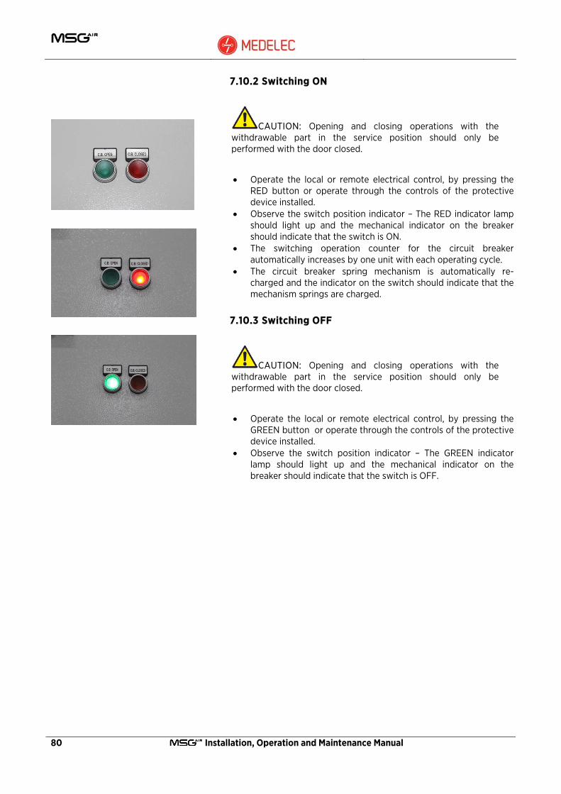
80 Installation, Operation and Maintenance Manual
7.10.2 Switching ON
CAUTION: Opening and closing operations with the withdrawable part in the service position should only be performed with the door closed.
• Operate the local or remote electrical control, by pressing the RED button or operate through the controls of the protective device installed.
• Observe the switch position indicator – The RED indicator lamp should light up and the mechanical indicator on the breaker should indicate that the switch is ON.
• The switching operation counter for the circuit breaker automatically increases by one unit with each operating cycle.
• The circuit breaker spring mechanism is automatically re-charged and the indicator on the switch should indicate that the mechanism springs are charged.
7.10.3 Switching OFF
CAUTION: Opening and closing operations with the withdrawable part in the service position should only be performed with the door closed.
• Operate the local or remote electrical control, by pressing the GREEN button or operate through the controls of the protective device installed.
• Observe the switch position indicator – The GREEN indicator lamp should light up and the mechanical indicator on the breaker should indicate that the switch is OFF.

Installation, Operation and Maintenance Manual 81
7.11 VT Compartment
7.11.1 Withdrawable VT
WARNING: Putting the VT truck in and out of service must be carried out with the door closed.
Refer also to the Circuit breaker insertion procedure section 7.3
7.11.1.1 Inserting the truck into the compartment
1. Open the lower Compartment (in case of a feeder VT) or Circuit breaker compartment (in case of busbar VT) door.
2. Move the VT truck on its trolley to the front of the panel compartment.
3. Move the trolley up to the relevant compartment. Align the interlocking tabs with the holes in the front panel and secure the trolley to the front of the panel.
4. If the panel is not flush with the substation floor, prepare wooden boards of the required thickness in front of the panel to compensate for the height difference.
5. Unlock the VT truck from the trolley by pressing the handles at the front of the VT truck towards the center and push the VT assembly into the panel.
6. When the front of the VT truck is aligned with the panel guides, release the handles and move the VT until the locking pins latch. The withdrawable VT is now mechanically coupled to the compartment.
7. Unlock the trolley and remove. 8. Insert and latch the two secondary plugs into the enclosure fixed
sockets. Lock the secondary plugs by pushing on the metallic handles.
9. Close the compartment door.
NOTE: If the withdrawable part handles are not properly latched, racking is not possible
The removal operation is similar to steps 1 to 9 above except that the operations described in 5 and 6 are carried out in reverse and the secondary plugs are detached before removal of the VT truck.

82 Installation, Operation and Maintenance Manual
7.11.1.2 Racking the VT truck to the service position
CAUTION: It is only possible to rack the VT truck to Service position with the VT door closed.
NOTE: The operations must be carried out using normal force (not more than 260 N), only using the special tools (see section 7.1). If the operation is prevented, check that the operating sequence is correct.
1. Make sure that the secondary plugs are inserted. 2. Close the panel door of the compartment. 3. Turn the knob located in the centre bottom of the door anti-
clockwise until the operating hole is exposed (remove the key if inserted).
4. Fit the short hand crank handle in the drive shaft and push to unlock the anti-racking mechanism.
5. Keep this push on the handle and rotate clockwise until the VT truck is fully inserted.
6. Remove the hand crank by rotating the knob anti-clockwise whilst withdrawing the handle out of the VT compartment door.
7. Release knob and ensure that the shutter returns to the fully closed position.
8. The VT truck is now locked in the Service position and is fully operational.
Withdrawal from the service position is according to steps 1 to 8 above except that the handle has to be rotated anti-clockwise.
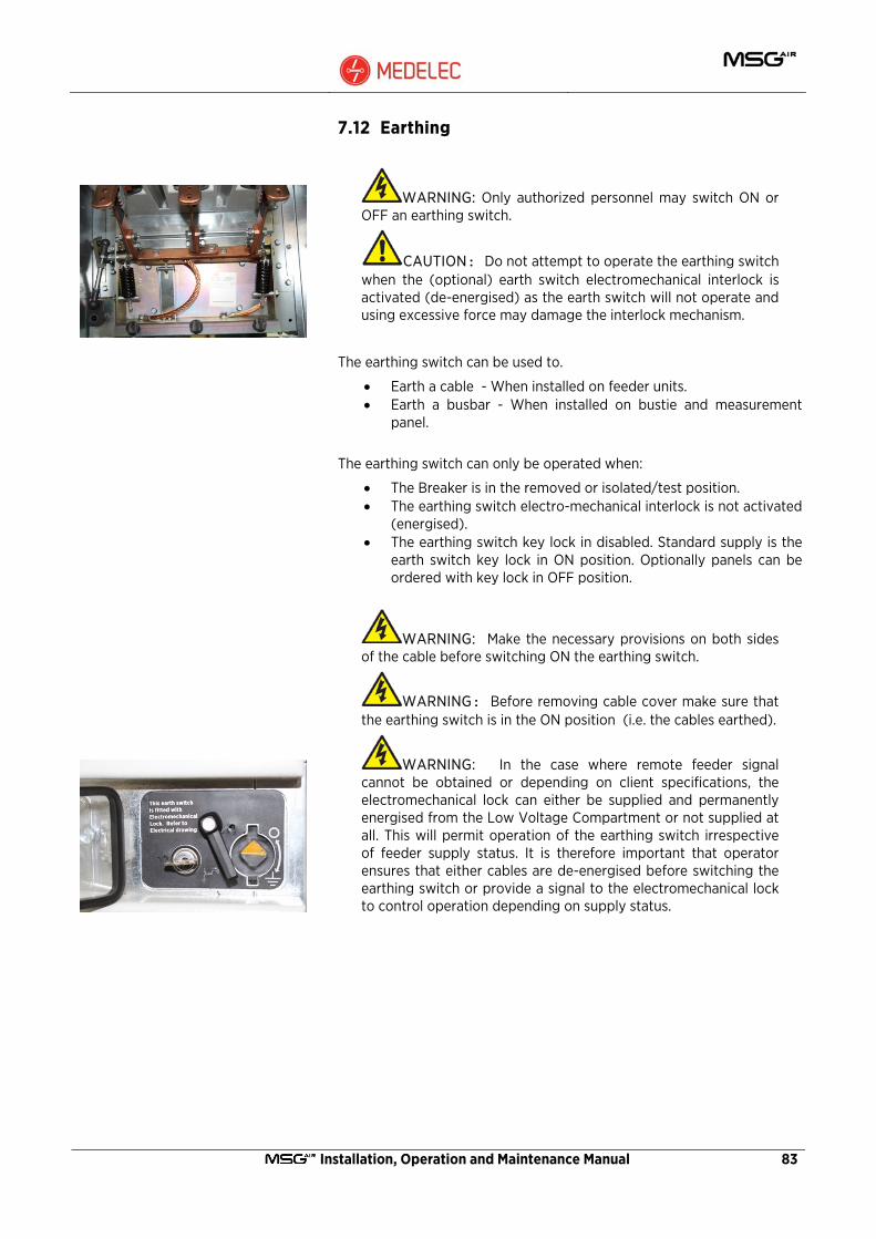
Installation, Operation and Maintenance Manual 83
7.12 Earthing
WARNING: Only authorized personnel may switch ON or OFF an earthing switch.
CAUTION: Do not attempt to operate the earthing switch when the (optional) earth switch electromechanical interlock is activated (de-energised) as the earth switch will not operate and using excessive force may damage the interlock mechanism.
The earthing switch can be used to.
• Earth a cable - When installed on feeder units. • Earth a busbar - When installed on bustie and measurement
panel.
The earthing switch can only be operated when:
• The Breaker is in the removed or isolated/test position. • The earthing switch electro-mechanical interlock is not activated
(energised). • The earthing switch key lock in disabled. Standard supply is the
earth switch key lock in ON position. Optionally panels can be ordered with key lock in OFF position.
WARNING: Make the necessary provisions on both sides of the cable before switching ON the earthing switch.
WARNING: Before removing cable cover make sure that the earthing switch is in the ON position (i.e. the cables earthed).
WARNING: In the case where remote feeder signal cannot be obtained or depending on client specifications, the electromechanical lock can either be supplied and permanently energised from the Low Voltage Compartment or not supplied at all. This will permit operation of the earthing switch irrespective of feeder supply status. It is therefore important that operator ensures that either cables are de-energised before switching the earthing switch or provide a signal to the electromechanical lock to control operation depending on supply status.
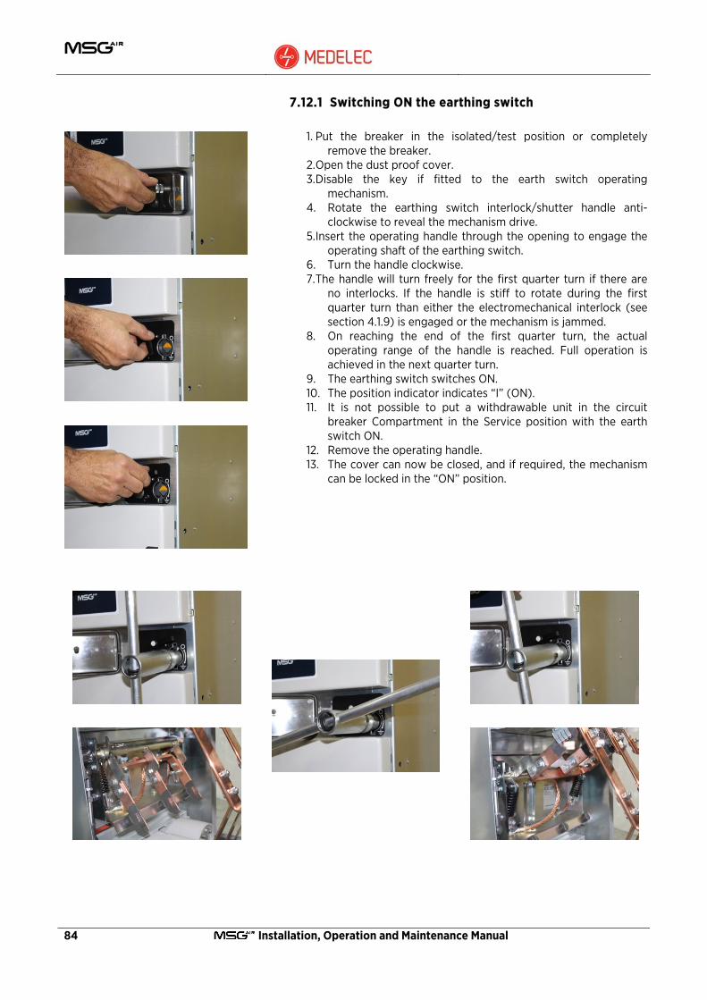
84 Installation, Operation and Maintenance Manual
7.12.1 Switching ON the earthing switch
1. Put the breaker in the isolated/test position or completely remove the breaker.
2. Open the dust proof cover. 3. Disable the key if fitted to the earth switch operating
mechanism. 4. Rotate the earthing switch interlock/shutter handle anti-
clockwise to reveal the mechanism drive. 5. Insert the operating handle through the opening to engage the
operating shaft of the earthing switch. 6. Turn the handle clockwise. 7. The handle will turn freely for the first quarter turn if there are
no interlocks. If the handle is stiff to rotate during the first quarter turn than either the electromechanical interlock (see section 4.1.9) is engaged or the mechanism is jammed.
8. On reaching the end of the first quarter turn, the actual operating range of the handle is reached. Full operation is achieved in the next quarter turn.
9. The earthing switch switches ON. 10. The position indicator indicates “I” (ON). 11. It is not possible to put a withdrawable unit in the circuit
breaker Compartment in the Service position with the earth switch ON.
12. Remove the operating handle. 13. The cover can now be closed, and if required, the mechanism
can be locked in the “ON” position.

Installation, Operation and Maintenance Manual 85
7.12.2 Switching OFF the earthing switch
1. Open the dust proof cover. 2. Release the key lock, if activated. 3. Insert the operating handle in the drive shaft of the earthing
switch. 4. Turn the handle anti-clockwise. 5. The handle will turn freely for the first quarter turn if there
are no interlocks. If the handle is stiff to rotate during the first quarter turn than either the electromechanical interlock is engaged or the mechanism is jammed.
6. On reaching the end of the first quarter turn, the actual operating range of the handle is reached. Full operation is achieved in the next quarter turn.
7. The earthing switch is switched OFF. 8. The position indicator indicates “O” (OFF). 9. Remove the operating handle. 10. Rotate the earthing switch interlock/shutter handle
clockwise to cover the mechanism drive. 11. Close the dust proof cover.
The withdrawable circuit breaker can now be inserted in the service position.
7.12.3 Optional Voltage Detection System VDS
The low voltage control panel may be fitted with a cable voltage indicator. These may vary in functionality as follows.
7.12.3.1 Voltage indicator
This is the standard equipment installed on the switchgear. A voltage indicator is an indicator with three LED’s and three socket contacts L1, L2 and L3. It is connected via a signal cable to a voltage sensor, which is located on the current transformer or special post insulators.
Each LED monitors one phase. The LEDs light up if a voltage is present on the phases. If the phases are dead the LEDs do not light up.
7.12.3.2 Live line cable interlock.
As an option, the can be fitted with a live line cable interlock. In this case the voltage indictor will operate a relay which can be used to electrically interlock other functions such as cable earthing.
For details refer to the specific user manual for the device fitted.
86 Installation, Operation and Maintenance Manual
8 Commissioning checks and test programme After the switchgear has been installed and all connections have been completed, it is recommended to perform the following commissioning tests. The purpose of these tests is to confirm that transportation and storage have not damaged the circuit breaker or any part of the fixed portion.
The purpose of the commission tests is to confirm:
• Absence of damage. • Compatibility of separate units. • Correct assembly. • Correct operation of the assembled unit.
The tests outlined in this section are to be performed after the equipment has been erected, but before energising.
8.1 General checks
• Check that the assembly has been performed to manufacturer's drawings and instructions.
• Check that the internal insulation components are undamaged and clean.
• Check adequacy and integrity of the earth connection up to and including the interface with the substation earthing system.
• Check all mechanical interlocks and free movement of the withdrawable units.(Circuit breakers and Withdrawable VTs)
• Check panel to panel wiring to confirm that it is according to specifications and drawings.
• Check the alignment of the racking access hole on the relevant door to withdrawable device racking drive as per procedure in section 6.12.

Installation, Operation and Maintenance Manual 87
8.2 Electrical tests
NOTE: To check the electrical operation, auxiliary supply to the switchgear has to be provided.
Ensure that the following checks have been carried out:
• Electrical closing and opening of circuit breaker at rated auxiliary voltage.
• Operation of auxiliary contacts, relays, coils and meters. • Perform wiring checks as per supplied drawings. • Check the contact resistance of the primary circuit. • Check the voltage drop on the busbar connections fitted on site. • Perform a withstand voltage test of the secondary circuit.
(Except the spring charging motors and electronic equipment). • Perform a withstand voltage test of the primary circuit except
the Voltage Transformer. Check the integrity of the vacuum interrupters. Should a breakdown occur, the circuit breaker should be kept out of service and the matter reported without delay to Medelec Switchgear Ltd.
(The integrity of the vacuum interrupters can be checked on site by applying a test voltage of 20kV AC r m s or 30kV DC for 2 or 3 seconds across the open contacts of each phase with the other side earthed. Provided that there is no evidence of breakdown the interrupter is in a satisfactory condition).
8.3 Mechanical Tests
Manual operational checks should be carried out on the circuit breaker to ensure correct operation of interlocks, primary connection safety shutters, operating mechanism, trips, auxiliary switches, manual spring charging and the circuit breaker racking mechanism.
The equipment should be given a final inspection before it is put into service.
• Check that all panel-to-panel fixings have been installed and secured.
• Check that all covers are in place and fully secured. • Check earth bars for continuity. • Check that all fuses and links are inserted. • Check that padlocks are fitted. • Check all moving parts of the safety shutters, the circuit breaker
racking mechanism, the isolatable voltage transformer operating mechanisms and all interlocks.
• Ensure all insulation surfaces are clean and dry. • Touch up paint work where necessary.
88 Installation, Operation and Maintenance Manual
8.4 Recording
In order that a complete history is available, records should be started immediately after erection.
Record the circuit breaker operations counter reading.
• Record the number on the operations counter at delivery. • Record the number on the operations counter at first
energisation. Records are of value in establishing the frequency of maintenance, therefore careful notes should be taken of relevant events (such as short circuit operations) each time maintenance is carried out. These readings can be logged in the table under Section 8.6
In order that a complete history is available, records should also be taken immediately after commissioning and during particular events. These should include:
• Date of Completion. • Details of any work carried out. • Event log and details of repair or maintenance work carried out.

Installation, Operation and Maintenance Manual 89
8.5 Check Lists A: COMMISIONING CHECK LIST
A 1 Equipment bolted down correctly.
A 2 Instrument panels straight and aligned.
A 3 All rubber gaskets and covers in place.
A 4 Check tightness of all fastenings.
A 5 All insulators undamaged and clean.
A 6 Earth strap connections.
A 7 Labelling.
A 8 Switchgear Heaters.
A 9 Isolating and Earthing Arrangements.
A 10 Circuit breaker and Mechanism Alignment.
A 11 Auxiliary Switches.
A 12 Voltage and current transformers checked.
A 13
B: Battery Checks:
B 1 Battery charged.
B 2 DC available throughout switchboard.
B 3 All fuses checked.
B 4 Battery disconnection links left in open/close position.
B 5
C: ELECTRICAL TESTS
C 1 High voltage tests carried out.
C 2 Primary and secondary injection tests carried out.
C 3 Main busbar voltage drop test carried out.
C 4 Meters and relays checked by secondary current injection and supply voltage
C 5
Remarks:
……………………………………………………………………………………………………………
……………………………………………………………………………………………………………
……………………………………………………………………………………………………………
TESTS CARRIED OUT BY: …………………………… DATE: …………………………………..
TESTS WITNESSED BY: ……………………………
EQUIPMENT ENERGISED: …………………………… DATE: …………………………………..

90 Installation, Operation and Maintenance Manual
8.6 Counter Recording
DESCRIPTION UNIT 1 UNIT 2 UNIT 3 UNIT 4 UNIT 5 UNIT 6 UNIT 7
Counter at delivery.
Counter at completion.
Other Details
________________________________________________________________________________________________________________________________________________________________________________________________________________________________________________________________________________________________________________________________________________________________________________________________________________________________________________________________________________________________________________________________________________________________________________________________________________________________________________________________________________________________________________________________________________________________________________________________________________________________________________________________________________________________________________________________________________________________________________________________________________________________________________________________________________________________________________________________________________________________________________________________________________________________________________________________________________________________________________________________________________________________________________________________________________________________________________________________________________________________________________________________________________________________________________________________________________________________________________________________________________________________________________________________________________________________________________________________________________________________________________________________________________________________________________________________________________________________________________________________________________________________________________________________________________________________________________________________________________________________________________________________________________________________________________________________________________________________________________________________________________________________________

Installation, Operation and Maintenance Manual 91
9 General Maintenance
Maintenance serves to preserve trouble-free operation and achieve the longest possible working life of the switchgear. It comprises the following closely related activities:
Inspection: Determination of the actual condition
Servicing: Measures to preserve the specified condition.
Repair: Measures to restore the specified condition.
WARNING: When carrying out all maintenance work, the regulations in the country of installation must be strictly complied with.
WARNING: Maintenance work may only be performed in a careful manner by trained personnel familiar with the characteristics of the individual switchgear, in accordance with all relevant IEC safety regulations and those of other technical authorities, and with other overriding instructions. It is recommended that Medelec service personnel be called in to perform the servicing and repair work detailed below.
CAUTION: The inspection and servicing intervals for some of the equipment/components (e.g. parts subjects to wear) are determined by fixed criteria, such as switching frequency, length of service and number of sort-circuit breaking operations. On the other hand, for other parts the length of the intervals may depend, for example, on the different modes of operation in individual cases, the degree of loading, and also environmental influences (including pollution and aggressive air).
The operating and instruction manual for Vacuum circuit breaker, type VD4, must also be followed.

92 Installation, Operation and Maintenance Manual
9.1 Intervals for inspection, servicing and repairs
Time intervals for maintenance work to be carried out always depend on the operating conditions of the switchgear, and mainly on the mode of operation, the number of rated and short-circuit current switching operations, ambient temperature, pollution etc. We recommend carrying out the maintenance work at the following intervals:
Activity According to Section
Time interval in years
According to number of switching operations
Inspection 9.2 4 (1)
Servicing 9.3 4 (2) 10000 (3)
Repair 9.4 As required As required
¹) In more demanding service conditions, we recommend reducing this interval suitably – also see section 1.3
²) According to the results of the inspection.
³) See the instruction manuals of the circuit breakers.
9.2 Inspection
WARNING: The working area must be isolated and secured against reconnection in accordance with the Safety Regulations specified by IEC and appropriate national standards before inspection.
CAUTION: Under normal operating conditions, inspection should be carried out according to the above schedule by specially trained professional electricians.
NOTE: Under abnormal operating conditions (including adverse climatic conditions) and/or special environmental stresses (heavy pollution and aggressive atmosphere, among others), inspection may be necessary at shorter intervals.
During these inspections, the condition of the switchgear should be monitored by carrying out:
• Visual inspection of the main switchgear components for grime, corrosion and moisture.
• Visual inspection for the effects of high temperature on the main circuits.
• Visual inspection for traces of partial discharge on the insulating material parts;
• Visual inspection of the surfaces of the contact systems, both primary and secondary for signs of corrosion.
Installation, Operation and Maintenance Manual 93
Inspection must also include correct mechanical/electrical operation of the following parts:
Switching devices, actuating, interlocking, protection and signalling devices.
9.3 Servicing
When, during an inspection as per paragraph 9.2, the need to carry out cleaning operations is noted, proceed as follows:
WARNING: The work area must be disconnected and locked against reconnection in conformity with the safety standards specified in the IEC directive and in the relative national regulations;
Clean the surfaces by:
• Removing any dry dust deposits, which are not very adherent, using a soft dry cloth or using a low alkaline detergent or with ETHANOL F 25 M in the case of more adhering dirt.
• Clean the insulating surfaces and the conductive components with ETHANOL F 25 M.
• After cleaning, rinse with clean water and dry carefully. • Should any partial discharges occur as a consequence of the
condensation phenomenon, a temporary remedy which is often effective is application of a thin layer of silicone over the surface involved. For a permanent remedy to this type of unusual problem, contact Medelec Switchgear Ltd.

94 Installation, Operation and Maintenance Manual
9.3.1 Maintenance in busbar compartment
WARNING: Make the plant you want to work on safe (follow the plant safety regulations).
• Remove the circuit breaker from the panel where you want to work or lock in the isolated/test position and close the earthing switch.
• Close the earthing switch relative to the main busbar section. • After removal of the unit upper rear cover and the busbar
compartment cover, the main busbars are visible. • Check busbars for signs of corrosion and discolouration due to
high temperature. • Using a torque wrench spanner, check tightness of all the screws
fixing the main busbars. Refer to the table on section 6.2.1 for the tightening values.
• Visually check that the upper insulation monoblock where the tulip isolating contact is housed are integral and do not show any deterioration or signs of partial discharge.
• Clean the insulating materials before replacing the removed covers.

Installation, Operation and Maintenance Manual 95
9.3.2 Maintenance in cable compartment
WARNING: Before opening the cable compartment door, make sure that the incoming feed is OFF and that the earthing switch is closed.
• Make sure that the circuit breaker is in the open position. • Rack the circuit breaker out from the service position to the
isolated/test position. • Manually close the earthing switch and lock in the closed
position. • Remove the unit lower rear cover or open the cable
compartment front door in the case of a wall mounted switchboard.
• Check busbars and cable connections for signs of corrosion and discolouration due to high temperature.
Internal view of the cable connection compartment.
9.3.2.1 Checking tightening of the power cable connections
Follow the procedure in Section 9.3.2. The cable connections are now visible.
• Using a torque wrench spanner, check tightness of all the screws. Refer to the table on section 6.2.1 for the tightening values.
• Visually check that the bottom monoblock where the tulip isolating contact is housed are integral and do not show any breakages or signs of partial discharge.
• Visually check that the insulating covering of the cable connections is integral and does not show any breakages.
• Clean all the insulating materials before closing the cable compartment cover.
9.3.2.2 Earthing switch – type ST-E
Follow the procedure in Section 9.3.2. The earthing switch and mechanism are now visible.
• Manually carry out 5 closing/opening operations of the earthing switch.
• Carry out a visual inspection of the mechanical connections and check for any presence of dirt, humidity and signs of corrosion on the main operating shaft and on the contact parts of the blades.
• Remove any deposits of dust using a dry cloth that does not leave any deposits on the treated surfaces (do not use woolen cloths).
• If necessary, grease the moving mechanical parts by applying a thin layer of mechanical grease for moving parts.
• Close the cable compartment cover.

96 Installation, Operation and Maintenance Manual
9.3.2.3 Cleaning and checking of current transformers
Follow the procedure in Section 9.3.2. The current transformers are now visible just above the rear cover.
• Visually check the connections of the current transformers. • Using a torque wrench spanner, check the tightness of all the
screws. Refer to the table on section 6.2.1 for the tightening values.
• Clean all the insulating materials before closing the cable compartment cover.
9.3.2.4 Cleaning, checking and replacement of the fixed voltage transformers
Follow the procedure in Section 9.3.2. The fixed Voltage transformers are now visible in the lower front chamber for feeder units or the rear of the cable compartment for riser and measurement units.
• Visually check the voltage transformer connections. • Using a torque wrench spanner, check the tightness of all the
screws. Refer to the table on section 6.2.1 for the tightening values.
• Carry out a visual inspection of the transformers and check for any presence of dirt or signs of partial discharge.
• Remove any deposits of dust using a dry cloth that does not leave any deposits on the treated surfaces (do not use woollen cloths).
Should it be necessary to replace the fixed voltage transformers, remove the secondary wiring and the primary connection. Unscrew the four bolts holding the VT to the supporting structure, and remove from the unit using the tool rack base plate shown in the photo to slide the voltage transformer out of the panel.
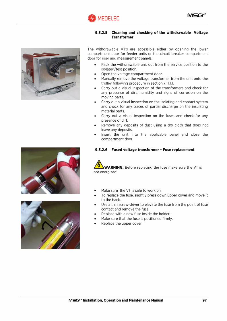
Installation, Operation and Maintenance Manual 97
9.3.2.5 Cleaning and checking of the withdrawable Voltage Transformer
The withdrawable VT’s are accessible either by opening the lower compartment door for feeder units or the circuit breaker compartment door for riser and measurement panels.
• Rack the withdrawable unit out from the service position to the isolated/test position.
• Open the voltage compartment door. • Manually remove the voltage transformer from the unit onto the
trolley following procedure in section 7.11.1.1. • Carry out a visual inspection of the transformers and check for
any presence of dirt, humidity and signs of corrosion on the moving parts.
• Carry out a visual inspection on the isolating and contact system and check for any traces of partial discharge on the insulating material parts.
• Carry out a visual inspection on the fuses and check for any presence of dirt.
• Remove any deposits of dust using a dry cloth that does not leave any deposits.
• Insert the unit into the applicable panel and close the compartment door.
9.3.2.6 Fused voltage transformer – Fuse replacement
WARNING: Before replacing the fuse make sure the VT is not energized!
• Make sure the VT is safe to work on, • To replace the fuse, slightly press down upper cover and move it
to the back. • Use a thin screw-driver to elevate the fuse from the point of fuse
contact and remove the fuse. • Replace with a new fuse inside the holder. • Make sure that the fuse is positioned firmly. • Replace the upper cover.
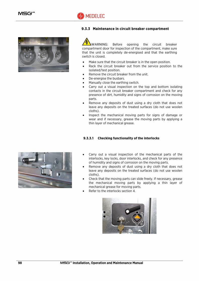
98 Installation, Operation and Maintenance Manual
9.3.3 Maintenance in circuit breaker compartment
WARNING: Before opening the circuit breaker compartment door for inspection of the compartment, make sure that the unit is completely de-energised and that the earthing switch is closed.
• Make sure that the circuit breaker is in the open position. • Rack the circuit breaker out from the service position to the
isolated/test position. • Remove the circuit breaker from the unit. • De-energise the busbars. • Manually close the earthing switch. • Carry out a visual inspection on the top and bottom isolating
contacts in the circuit breaker compartment and check for any presence of dirt, humidity and signs of corrosion on the moving parts.
• Remove any deposits of dust using a dry cloth that does not leave any deposits on the treated surfaces (do not use woolen cloths).
• Inspect the mechanical moving parts for signs of damage or wear and if necessary, grease the moving parts by applying a thin layer of mechanical grease.
9.3.3.1 Checking functionality of the interlocks
• Carry out a visual inspection of the mechanical parts of the interlocks, key locks, door interlocks, and check for any presence of humidity and signs of corrosion on the moving parts.
• Remove any deposits of dust using a dry cloth that does not leave any deposits on the treated surfaces (do not use woolen cloths).
• Check that the moving parts can slide freely. If necessary, grease the mechanical moving parts by applying a thin layer of mechanical grease for moving parts.
• Refer to the interlocks section 4.

Installation, Operation and Maintenance Manual 99
9.3.4 Checking correct operation of the protection relay
• Make the plant you want to work on safe (follow the plant safety regulations).
• Make sure that the circuit breaker is in the open position. • Rack the circuit breaker out from the service position to the
isolated/test position. • Manually close the earthing switch. • Carry out secondary injections to check perfect operation of the
protection relays.
NOTE: To check operation of the protection relay, refer to the manufacturing operating manual of the protection relay provided.
9.3.5 Cleaning and checking the auxiliary connections
• Make the plant you want to work on safe (follow the plant safety regulations).
• Make sure that the circuit breaker is in the open position. • Rack the circuit breaker out from the service position to the
isolated/test position. • Manually close the earthing switch. • Open the miniature circuit breakers positioned inside the low
voltage compartment to switch off the auxiliary power supply to the panel.
• Carry out a visual inspection on all the cabling, terminal boxes and check for any presence of dirt.
• Manually check correct tightness of the terminal blocks.

100 Installation, Operation and Maintenance Manual
9.4 Repairs
9.4.1 Switchgear in general
Repair of surface damage:
• Carry out repair work immediately after a defect has been discovered.
• Carefully remove any white rust from passivated operating parts and rust formation on phosphatised parts with a wire brush or metal-free cleaning pad, e.g. Scotch-Brite, and clean with a dry cloth. Then grease evenly (with mechanical grease for moving parts).
Apparatus in general:
• Follow the maintenance instructions in the manuals for individual equipment components.
• Check that the bolt connections at the contact points in the busbar system and the earth connections are tight, and that the contact system functions correctly.
• Where necessary, grease slide plates and bearings in the panel again or thoroughly clean them. Then grease them again with mechanical grease for moving parts.
• Re-apply grease on contact areas in the contact system when corroded or otherwise as necessary, or, when lubrication is inadequate or missing, thoroughly clean the areas concerned and grease them again with mechanical grease suitable for moving parts.
9.5 Testing interlock conditions
Test individual interlocks following the table in Section 4.1. Each condition has to be tested individually for correct functionality.
9.6 Spare parts, auxiliary materials and lubricants
9.6.1 Spare parts
A spare parts list is available on request for procurement of spare parts. It basically includes moving parts and parts subject to wear. When parts are required, the serial number of the relative switchgear or switching device should always be quoted.

Installation, Operation and Maintenance Manual 101
9.6.2 Accessories, Auxiliary materials and lubricants
Refer to list of accessories and tools listed in section 7.1
Lubricant
• Vaselina as oxidation protection for busbars. • Mechanical grease for moving parts.
Halogen-free cleansers
• ETHANOL F 25 M (for general cleaning).
Touch-up paint
• Standard colour RAL 7035.
102 Installation, Operation and Maintenance Manual
Notes

Installation, Operation and Maintenance Manual 103
104 Installation, Operation and Maintenance Manual

Installation, Operation and Maintenance Manual 105

Head Office & factOryBLB033, Bulebel industrial estate, Zejtun ZtN 3000
P.O. Box 20, Paola PLa 1001, Malta.t. (+356) 21693750 - f. (+356) 21693754 - e. [email protected]
triPOLi OfficeMadaris el funun W assanaqa
Building 82, flat 9, 24th december Street, P.O. Box 82118, tripoli, Libya.t. & f. (+218) 21 4444050
www.medelec-switchgear.com Bd
OM
02-
r0
-en.
2015
.01 -
MSG
air
Ope
ratio
ns, i
nsta
llatio
n an
d M
aint
enan
ce M
anua
l. W
e re
serv
e th
e rig
ht to
mak
e ch
ange
s in
the
cou
rse
of te
chni
cal d
evel
opm
ent.


