111
Operator and parts manual - 2013 OPERATOR AND PARTS MANUAL Some of the options described in this manual may not apply to your equipment HMI Password : 12345678
| Date post: | 02-May-2018 |
| Category: |
Documents |
| Upload: | phungtuong |
| View: | 220 times |
| Download: | 1 times |

Operator and parts manual - 2013
OPERATOR AND PARTS MANUAL
Some of the options described in this manual may not apply to your equipment
HMI Password : 12345678

AE612MKII, AE616MKII Stand Alone Labeling Machine
Operator and parts manual – 2012 Page i
TABLE OF CONTENTS 1 MANUAL PREFACE - Machine Identification ................................................................................ 5
2 CERTIFICATION APPROVALS........................................................................................................ 5
3 WARNINGS AND CAUTION INFORMATION .................................................................................. 6
4 PRODUCT INTRODUCTION .......................................................................................................... 8
4.1 OVERVIEW - GETTING TO KNOW THE LABELING HEAD ....................................................................................... 9
4.1.1 AE612MKII.................................................................................................................................... 9 4.1.2 AE616MKII.................................................................................................................................. 10 4.1.3 AE612 TAMP BLOW .................................................................................................................... 11 4.1.4 AE612 VERTICAL FORM FILL & SEAL (VFFS) ................................................................................. 12
4.2 DIMENSIONS ....................................................................................................................................... 13
4.2.1 STAND ALONE LEFT HAND WITH U ARM AND T STAND ............................................................... 14 4.2.2 STAND ALONE RIGHT HAND WITH U ARM AND T STAND ............................................................ 15 4.2.3 STAND ALONE LEFT HAND WITH LATERAL ADJUSTMENT AND T STAND ...................................... 16 4.2.4 STAND ALONE RIGHT HAND WITH LATERAL ADJUSTMENT AND T STAND.................................... 17
5 SHIPMENT RECEPTION (uncrating) ............................................................................................ 18
6 SYSTEM SETUP ......................................................................................................................... 19
6.1 VERTICAL UP/DOWN ADJUSTMENT ............................................................................................................ 19
6.2 LABELING HEAD POSITIONING ADJUSTMENTS ............................................................................................ 21
6.2.1 Lateral adjustment ..................................................................................................................... 21 6.2.2 Angle adjustments ...................................................................................................................... 22 6.2.3 Peel plate angle adjustments ...................................................................................................... 23 6.2.4 Labeling head mount .................................................................................................................. 24
6.3 LOADING & UNLOADING THE LABEL STOCK ROLL ............................................................................................ 26
6.4 CONNECTIVITY AND LABELER HEAD MANUAL FEED CONTROL BUTTON................................................................. 30
6.5 SETTING THE LABEL GAP SENSOR ............................................................................................................... 31
6.5.1 Standard GAP sensor – for Opaque labels Tritronic model # LER ................................................. 31 6.5.2 GAP sensor for transparent label Tritronic Model # CLS .............................................................. 32 6.5.3 GAP sensor for transparent label SICK Model # UF3 .................................................................... 33 6.5.4 GAP Sensor calibration - Quick procedure – SICK Model UF3 ...................................................... 34 6.5.5 GAP sensor calibration - CLEAR label - Quick procedure Di-Soric Model # KSSTI 1000 (Capacitive - Black) 35
6.6 PRODUCT SENSORS .................................................................................................................................. 36
7 HMI – Getting to know the HMI touch screen – Operator interface ........................................... 37
7.1 START UP SCREEN .................................................................................................................................... 37

AE612MKII, AE616MKII Stand Alone Labeling Machine
Operator and parts manual – 2012 Page ii
7.2 MAIN MENU SCREEN ................................................................................................................................ 38
7.3 THE THREADING SCHEMATIC CAN BE OBTAINED BY PRESSING THE LABEL ROLL ICON ON THE TOP OF THE SCREEN. FOR
MORE INFORMATION ALSO REFER TO THE THREADING DIAGRAM IN THIS MANUAL............................................................ 40
7.4 RULER VALUES .................................................................................................................................... 41
7.5 OFFSET SCREEN ....................................................................................................................................... 42
7.5.1 Without encoder ........................................................................................................................ 42 7.5.2 Offset screen (with encoder) ...................................................................................................... 44
7.6 GENERAL SETTINGS SCREEN ....................................................................................................................... 47
7.7 ADVANCED SETTINGS ............................................................................................................................... 48
7.7.1 Change Password ....................................................................................................................... 48 7.7.2 Input screen ............................................................................................................................... 48 7.7.3 Labeling ...................................................................................................................................... 49 7.7.4 Servo motor rotation direction Screen ........................................................................................ 50 7.7.5 Encoder setting screen ............................................................................................................... 51 7.7.6 Encoder polarity screen .............................................................................................................. 51
7.8 CALIBRATE SCREEN .................................................................................................................................. 52
7.9 SAVING & OPENING RECIPE SCREEN ............................................................................................................ 53
7.9.1 The Help screens ........................................................................................................................ 54 7.10 ALARM SCREEN ....................................................................................................................................... 54
8 MAINTENANCE ......................................................................................................................... 56
9 TROUBLE SHOOTING – QUICK GUIDE ........................................................................................ 60
10 ELECTRICAL SCHEMATIC ........................................................................................................ 62
10.1 GENERAL DIAGRAM ................................................................................................................................. 62
10.2 COMMUNICATION CABLE .......................................................................................................................... 63
10.3 MOTOR ALIMENTATION CABLE .................................................................................................................. 63
10.4 FEED BACK ENCODER CABLE ....................................................................................................................... 64
10.5 ENCODER CABLE PANEL MOUNT (DB9M & DB9F) ........................................................................................ 65
11 WARRANTY........................................................................................................................... 67
12 PARTS - COMPONENTS SCHEMATICS SECTION ....................................................................... 69
12.1 PARTS LIST .......................................................................................................................................... 69
12.2 AE612MKII - OVERVIEW (RIGHT & LEFT HAND) ........................................................................................... 73

AE612MKII, AE616MKII Stand Alone Labeling Machine
Operator and parts manual – 2012 Page iii
12.2.1
74 12.2.2 AE612MKII - Main body & accessories ........................................................................................ 75 12.2.3 AE612MKII - Peel plate assy ........................................................................................................ 76 12.2.4 AE612MKII - Driver roller & motor assy ...................................................................................... 77 12.2.5 AE612MKII - Guard & tension roller ............................................................................................ 77 12.2.6 AE612MKII - Deflection & tension plate ...................................................................................... 78 12.2.7 AE612MKII - Unwind roller ......................................................................................................... 78 12.2.8 AE612MKII- Rewind roller ........................................................................................................... 79 12.2.9 AE612MKII - Unwind brake ......................................................................................................... 79 12.2.10 AE612MKII - Aluminum idler roller ............................................................................................. 80 12.2.11 AE612MKII - Deflection ribbon arm ............................................................................................ 80
12.3 AE612MKII WIDE - OVERVIEW WIDE LABELER HEAD (RIGHT & LEFT HAND) ...................................................... 81
AE612MKII, AE616MKII Stand Alone Labeling Machine
Operator and parts manual – 2012 Page iv
12.3.1 AE612MKII WIDE - Main body & accessories ............................................................................... 83 12.3.2 AE612MKII WIDE - Peel plate assy .............................................................................................. 84 12.3.3 AE612MKII WIDE - Driver roller & motor assy ............................................................................. 85 12.3.4 AE612MKII WIDE - Guard & tension roller .................................................................................. 85 12.3.5 AE612MKII WIDE - Deflection & tension plate............................................................................. 86 12.3.6 AE612MKII WIDE - Unwind roller (same as standard head) ......................................................... 86 12.3.7 AE612MKII WIDE - Rewind roller ................................................................................................ 87 12.3.8 AE612MKII WIDE - Unwind brake ............................................................................................... 87 12.3.9 AE612MKII WIDE - Aluminium idler roller ................................................................................... 88 12.3.10 AE612MKII WIDE – Deflection ribbon arm .................................................................................. 88
12.4 AE612MKII EXTRA-WIDE LABELER HEAD (RIGHT & LEFT HAND) ...................................................................... 89
12.4.1 AE612MKII Extra-Wide - Main body & accessories ...................................................................... 91 12.4.2 AE612MKII Extra-Wide - Peel system .......................................................................................... 92 12.4.3 AE612MKII Extra-Wide - Driver roller & motor assy .................................................................... 93 12.4.4 AE612MKII Extra-Wide - Guard & tension roller .......................................................................... 93 12.4.5 AE612MKII Extra-Wide - Deflection & tension plate .................................................................... 94 12.4.6 AE612MKII Extra-Wide - Unwind roller (same as standard head) ................................................ 94 12.4.7 AE612MKII Extra-Wide - Rewind roller ........................................................................................ 95 12.4.8 AE612MKII Extra-Wide - Unwind brake ....................................................................................... 95 12.4.9 AE612MKII Extra-Wide - Aluminium idler roller .......................................................................... 96 12.4.10 AE612MKII Extra-Wide - Deflection ribbon arm .......................................................................... 96
12.5 AE-616MKII MOTORIZED LABELER HEAD (RIGHT & LEFT HAND) ..................................................................... 97
12.5.1 AE616MKII Motorized Labeler head - Main body & accessories .................................................. 99 12.5.2 AE616MKII Motorized Labeler head - Peel plate assy ................................................................ 100 12.5.3 AE616MKII Motorized Labeler head - Driver roller & motor assy............................................... 101 12.5.4 AE616MKII Motorized Labeler head - Guard & tension roller .................................................... 101 12.5.5 AE616MKII Motorized Labeler head - Deflection & tension plate .............................................. 102 12.5.6 AE616MKII Motorized Labeler head - Ø16” Unwind roller......................................................... 102 12.5.7 AE-616MKII Motorized Labeler head - Rewind roller ................................................................. 103 12.5.8 AE616MKII Motorized Labeler head - Motorized rewind assy ................................................... 103 12.5.9 AE616MKII Motorized Labeler head - Unwind brake ................................................................. 104 12.5.10 AE616MKII Motorized Labeler head - Aluminum idler roller...................................................... 104 12.5.11 AE-616MKII Motorized Labeler head - Deflection ribbon arm ................................................... 105
12.6 LATERAL ADJUSTMENT ........................................................................................................................... 106
12.7 U-ARM ............................................................................................................................................... 106
12.8 BRUSH KIT ........................................................................................................................................... 107
12.9 WIDE BRUSH KIT................................................................................................................................... 108
12.10 STAINLESS STEEL T BASE FLOOR STAND................................................................................................. 108
12.11 PAINTED STEEL T BASE FLOOR STAND ................................................................................................... 109
12.12 SLIDING CART ................................................................................................................................... 109
AE612MKII, AE616MKII Stand Alone Labeling Machine
Operator and parts manual – 2012 Page v
13 MANUFACTURER’S COORDINATES ...................................................................................... 110
1 MANUAL PREFACE - Machine Identification
This Manual will provide operating instructions, parts listing and schematics for the AE MKII labeling head built by Nita Labeling Equipment, Inc. The information contained in this manual will help the user in his/ her operations, troubleshooting and maintaining the machine in good operating condition.
Information, illustrations and specifications contained in this manual are based on the latest product information available at the time of this manual release. Nita Labeling equipment, Inc. reserves the right to alter and substitute information contained herein at any time.
This equipment is intended to be used only as described in this document. NITA Labeling Equipment, Inc. cannot be held responsible for the improper use of the machinery as is outlined in the document herein. Liability for any personal injury, loss of production or revenues, or property damage caused by the use of this manual in the context of maintenance; operation, or repair of the equipment is in no way assumed by NITA Labeling Equipment, Inc. Anyone using a procedure not recommended by the end user should first completely satisfy himself/herself that personal safety and equipment integrity will not be jeopardized in the method selected.
All rights reserved
While every precaution has been taken in the preparation of this manual, Nita Labeling Equipment, Inc. assumes no responsibility for errors or omissions. Neither is any liability assumed for damages, loss or production, or revenues resulting from the use of the information contained herein
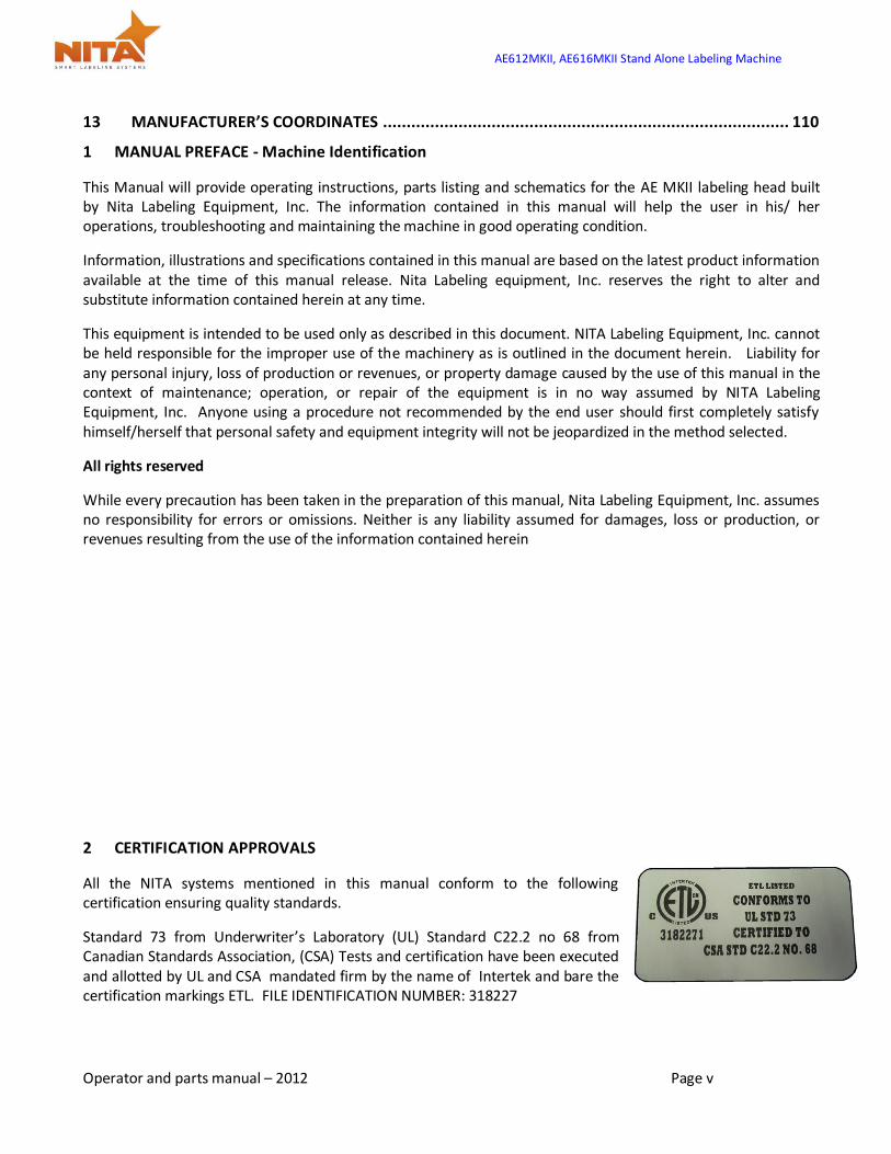
2 CERTIFICATION APPROVALS
All the NITA systems mentioned in this manual conform to the following certification ensuring quality standards.
Standard 73 from Underwriter’s Laboratory (UL) Standard C22.2 no 68 from Canadian Standards Association, (CSA) Tests and certification have been executed and allotted by UL and CSA mandated firm by the name of Intertek and bare the certification markings ETL. FILE IDENTIFICATION NUMBER: 318227

AE612MKII, AE616MKII Stand Alone Labeling Machine
Operator and parts manual – 2012 Page 6 of 111
3 WARNINGS AND CAUTION INFORMATION
Machine use disclaimer
This equipment must NOT be used for the purposes other than for which it has been supplied to the customer under the purchase agreement and reflected in the quotation provided to the distributor or end user prior to purchase. Failure to use the equipment for the purpose described in this manual nullifies any warranty claim or injury claim that could arise as a result.
AE612MKII, AE616MKII Stand Alone Labeling Machine
Operator and parts manual – 2012 Page 7 of 111
Safety
Be certain that the operators and maintenance personnel read this manual before attempting to operate perform maintenance or service to this equipment. Failure to follow these instructions could possibly result in serious personal injury, and cause damage to the equipment, or its components. Recognize safety symbols, words, and labels. Warning and Safety Instructions appearing in this manual are not meant to cover all possible conditions and situations that can occur. Common sense, caution, and care must always be exercised when installing, maintaining, servicing or operating this equipment.
The AE MKII series is engineered to feed and apply labels on your products. In designing this device, NITA valued personal safety; however we would like to draw your attention to the following safety acknowledgments.
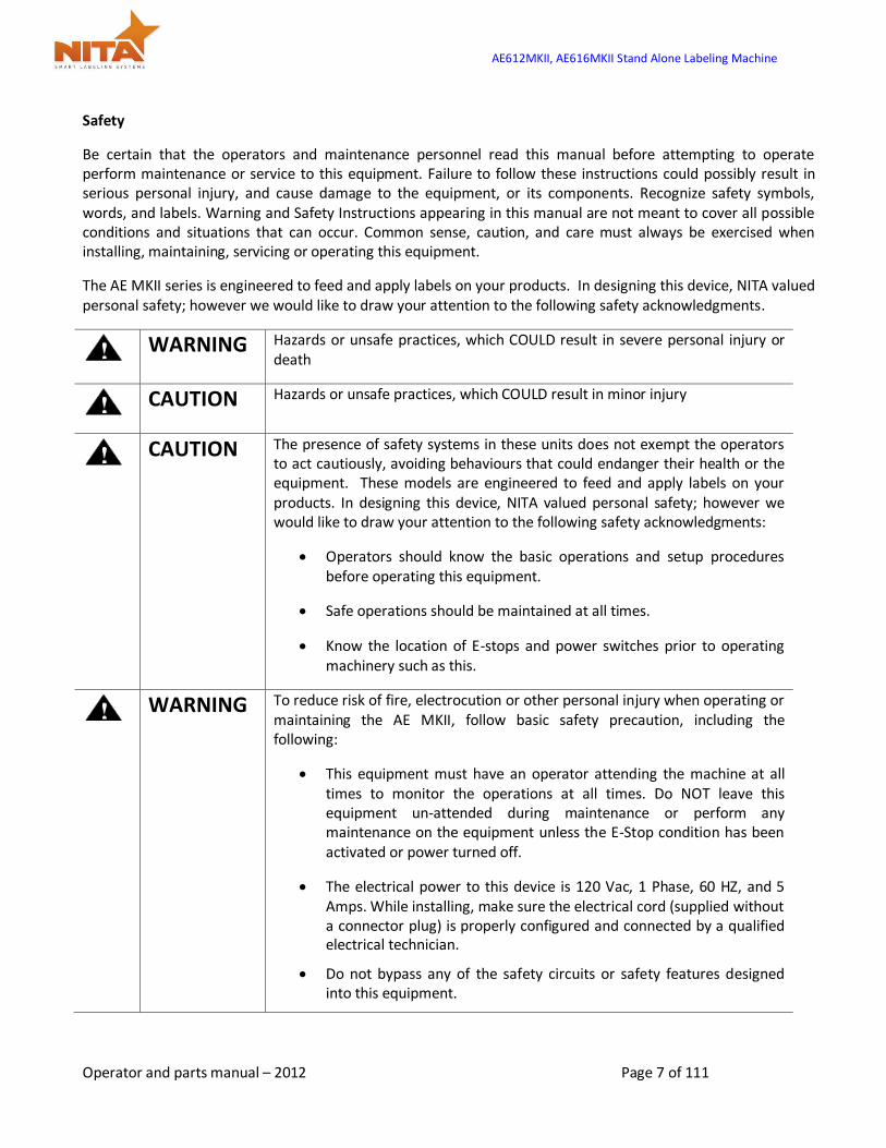
WARNING Hazards or unsafe practices, which COULD result in severe personal injury or
death
CAUTION Hazards or unsafe practices, which COULD result in minor injury
CAUTION The presence of safety systems in these units does not exempt the operators
to act cautiously, avoiding behaviours that could endanger their health or the equipment. These models are engineered to feed and apply labels on your products. In designing this device, NITA valued personal safety; however we would like to draw your attention to the following safety acknowledgments:
Operators should know the basic operations and setup procedures before operating this equipment.
Safe operations should be maintained at all times.
Know the location of E-stops and power switches prior to operating machinery such as this.
WARNING To reduce risk of fire, electrocution or other personal injury when operating or
maintaining the AE MKII, follow basic safety precaution, including the following:
This equipment must have an operator attending the machine at all times to monitor the operations at all times. Do NOT leave this equipment un-attended during maintenance or perform any maintenance on the equipment unless the E-Stop condition has been activated or power turned off.
The electrical power to this device is 120 Vac, 1 Phase, 60 HZ, and 5 Amps. While installing, make sure the electrical cord (supplied without a connector plug) is properly configured and connected by a qualified electrical technician.
Do not bypass any of the safety circuits or safety features designed into this equipment.
AE612MKII, AE616MKII Stand Alone Labeling Machine
Operator and parts manual – 2012 Page 8 of 111
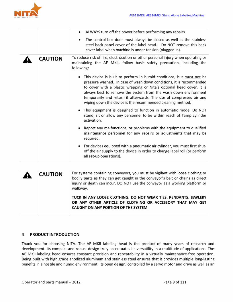
ALWAYS turn off the power before performing any repairs.
The control box door must always be closed as well as the stainless steel back panel cover of the label head. Do NOT remove this back cover label when machine is under tension (plugged in).
CAUTION To reduce risk of fire, electrocution or other personal injury when operating or
maintaining the AE MKII, follow basic safety precaution, including the following:
This device is built to perform in humid conditions, but must not be pressure washed. In case of wash down conditions, it is recommended to cover with a plastic wrapping or Nita’s optional head cover. It is always best to remove the system from the wash down environment temporarily and return it afterwards. The use of compressed air and wiping down the device is the recommended cleaning method.
This equipment is designed to function in automatic mode. Do NOT stand, sit or allow any personnel to be within reach of Tamp cylinder activation.
Report any malfunctions, or problems with the equipment to qualified maintenance personnel for any repairs or adjustments that may be required.
For devices equipped with a pneumatic air cylinder, you must first shut-off the air supply to the device in order to change label roll (or perform all set-up operations).
CAUTION For systems containing conveyors, you must be vigilant with loose clothing or
bodily parts as they can get caught in the conveyor’s belt or chains as direct injury or death can incur. DO NOT use the conveyor as a working platform or walkway.
TUCK IN ANY LOOSE CLOTHING. DO NOT WEAR TIES, PENDANTS, JEWLERY OR ANY OTHER ARTICLE OF CLOTHING OR ACCESSORY THAT MAY GET CAUGHT ON ANY PORTION OF THE SYSTEM
4 PRODUCT INTRODUCTION
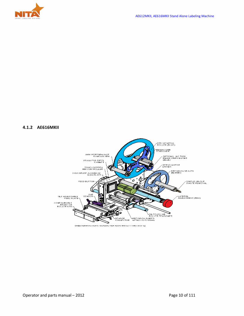
Thank you for choosing NITA. The AE MKII labeling head is the product of many years of research and development. Its compact and robust design truly accentuates its versatility in a multitude of applications. The AE MKII labeling head ensures constant precision and repeatability in a virtually maintenance-free operation. Being built with high grade anodized aluminum and stainless steel ensures that it provides multiple long-lasting benefits in a hostile and humid environment. Its open design, controlled by a servo motor and drive as well as an

AE612MKII, AE616MKII Stand Alone Labeling Machine
Operator and parts manual – 2012 Page 9 of 111
HMI touch screen operator interface, offers great flexibility suited to handling the most demanding labeling applications. In certain cases the labeling head is sold as a stand-alone unit while other times it is incorporated onto a T-base stand. In this case, the caster wheels have already been added to the T-base foot stand in order to facilitate the transport its final destination. Generally the equipment comes crated to avoid any damage. The crate should be transported with a pallet (skid) remover.
It is also possible that you have received your equipment without any T-base stand. See the dimensions of your equipment in the section “Machine identification”. Some pictures may be expressed in this manual using labeling heads on these said systems and may not totally reflect your configuration, although the labeling is completely the same.
It is also possible that you have received the AE MKII labeling head without any stand. The dimensions below reflect the AE MKII labeling head as head only unit.
MODEL AE612 label applicator
Physical Dimensions L 36" x H 23" x D 20 "
Power Requirements 120 Vac 5 Amp, 50/60 Hz, 1 phase
Air Requirements Only with Tamp blow 95 Psi/ 3 Scfm * WEIGHT = 45 LBS WITHOUT STAND
A labeling head is generally used to apply pressure sensitive labels onto boxes, cartons, plastic, glass containers or magazines as well as more hardware type products or can also be metal as well as wood products. It is commonly used in almost every sector of manufacturing.
A labeling head can be a stand-alone machine and does not require the use of a computer or label software program in order to perform its operations. It is generally built to automatically dispense one label at a time, having different media roll widths and can only run to the maximum speed determined by its components, which in this case is 1570 inches / minute. It generally receives a signal from a product sensor to allow the dispensing of a label onto a specific product.
4.1 Overview - Getting to know the labeling head
4.1.1 AE612MKII
AE612MKII, AE616MKII Stand Alone Labeling Machine
Operator and parts manual – 2012 Page 10 of 111
4.1.2 AE616MKII

AE612MKII, AE616MKII Stand Alone Labeling Machine
Operator and parts manual – 2012 Page 11 of 111
4.1.3 AE612 TAMP BLOW

AE612MKII, AE616MKII Stand Alone Labeling Machine
Operator and parts manual – 2012 Page 12 of 111
4.1.4 AE612 VERTICAL FORM FILL & SEAL (VFFS)
AE612MKII, AE616MKII Stand Alone Labeling Machine
Operator and parts manual – 2012 Page 13 of 111
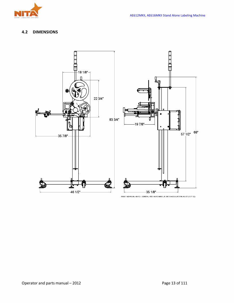
4.2 DIMENSIONS

AE612MKII, AE616MKII Stand Alone Labeling Machine
Operator and parts manual – 2012 Page 14 of 111
4.2.1 STAND ALONE LEFT HAND WITH U ARM AND T STAND

AE612MKII, AE616MKII Stand Alone Labeling Machine
Operator and parts manual – 2012 Page 15 of 111
4.2.2 STAND ALONE RIGHT HAND WITH U ARM AND T STAND
AE612MKII, AE616MKII Stand Alone Labeling Machine
Operator and parts manual – 2012 Page 16 of 111
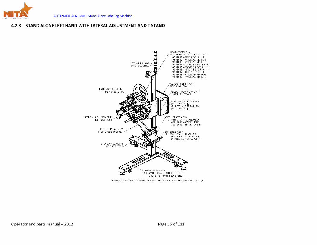
4.2.3 STAND ALONE LEFT HAND WITH LATERAL ADJUSTMENT AND T STAND
AE612MKII, AE616MKII Stand Alone Labeling Machine
Operator and parts manual – 2012 Page 17 of 111
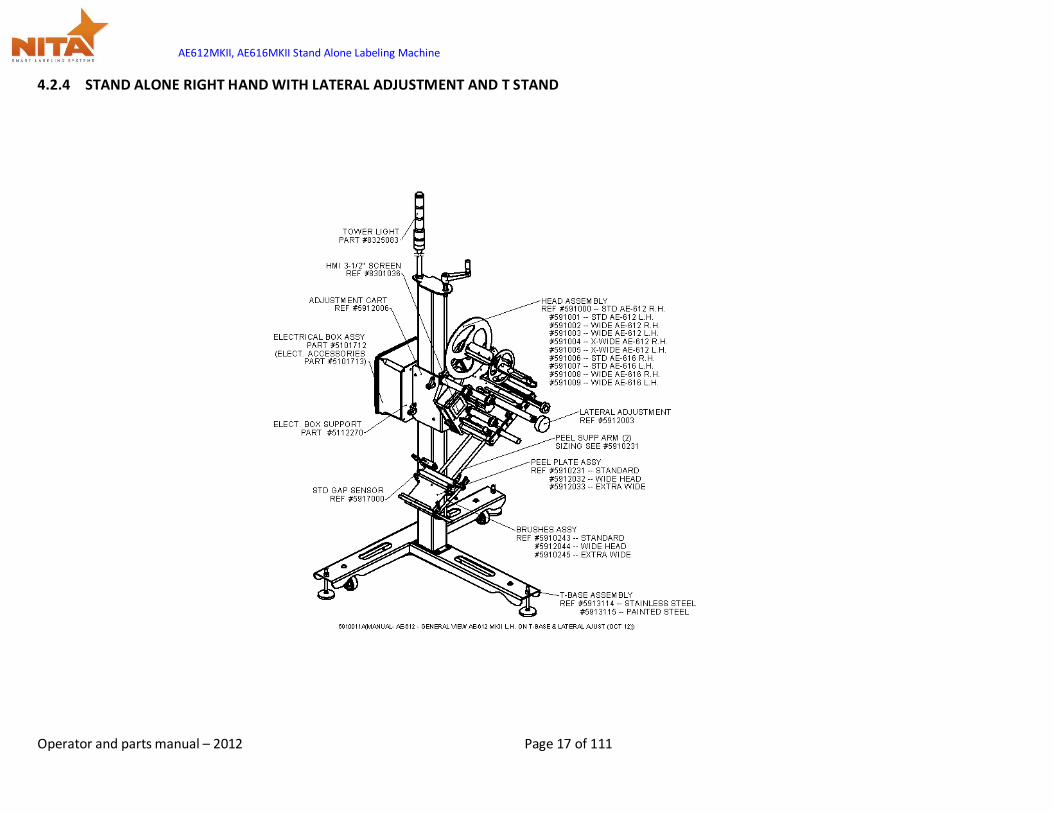
4.2.4 STAND ALONE RIGHT HAND WITH LATERAL ADJUSTMENT AND T STAND
AE612MKII, AE616MKII Stand Alone Labeling Machine
Operator and parts manual – 2012 Page 18 of 111
5 SHIPMENT RECEPTION (uncrating)
For shipping purposes, the T-base foot stand and the labeling head are crated together. This avoids any damage to the device as well as protects the adjustment settings allowing for a very stable product once installed in its final destination.
The crate is generally pop-nailed together and can be taken apart by using a simple hammer or a nail crowbar. Proceed in removing the side wood panels from the crate and work your way inward.
WARNING Always be vigilant while using any tools as they can result in bodily injury.
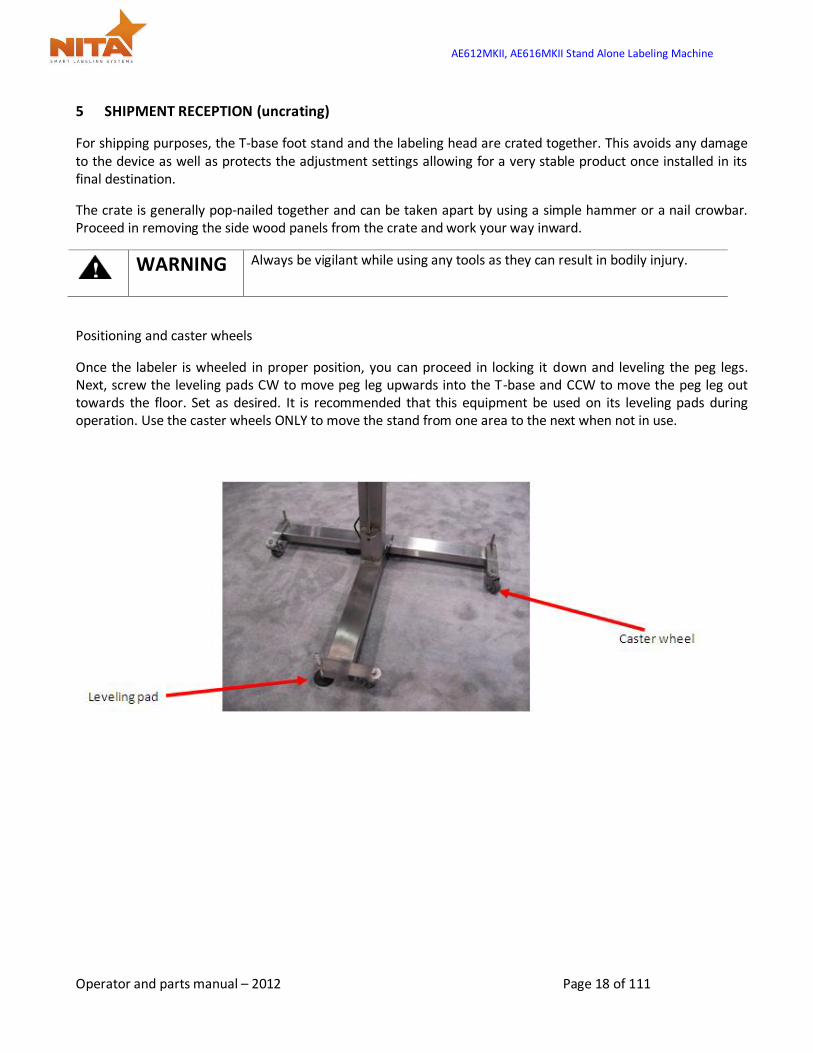
Positioning and caster wheels
Once the labeler is wheeled in proper position, you can proceed in locking it down and leveling the peg legs. Next, screw the leveling pads CW to move peg leg upwards into the T-base and CCW to move the peg leg out towards the floor. Set as desired. It is recommended that this equipment be used on its leveling pads during operation. Use the caster wheels ONLY to move the stand from one area to the next when not in use.

AE612MKII, AE616MKII Stand Alone Labeling Machine
Operator and parts manual – 2012 Page 19 of 111
6 SYSTEM SETUP
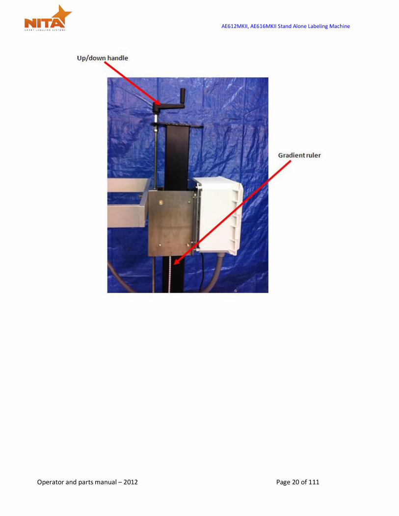
6.1 Vertical Up/Down adjustment
For height adjustments: The system is equipped with ratchet type handles. Lift the handle with the orange center by pressing down on the center to access the unlocking mechanism of the handle. Loosening this ratchet handle will allow you to unlock the up/down movement. Next, using the top handle turn it CW to raise the label head and CCW to lower the label head. Use the ruler to obtain perfect positioning as per your requirements.
Once in desired position, proceed in locking the handle once more by tightening and using the orange button to enable CW rotation of handle. Rulers make it easy to position in same area time and time again.
AE612MKII, AE616MKII Stand Alone Labeling Machine
Operator and parts manual – 2012 Page 20 of 111
AE612MKII, AE616MKII Stand Alone Labeling Machine
Operator and parts manual – 2012 Page 21 of 111
6.2 Labeling head POSITIONING adjustments
REMEMBER that Nita provides anodized coloring for any adjustments. A part anodized in red color indicates a crucial adjustment directly linked to the application of the label. Whereas a Blue color anodized part indicates a possible adjustment point. The labeling head is attached by either a U arm bracket mount (allowing a pivot) or a lateral mount adjustment (which allows for the lateral displacement over a conveyor). This support provides the first degree of freedom, thus a vertical movement. This mount is generally fixed on a horizontal pole called the T-base stand. On the side of the T-base stand, you will notice that there are gradient rulers. This allows the operator to properly identify the positioning of the labeler in order to reach optimum positioning results with respects to the product.
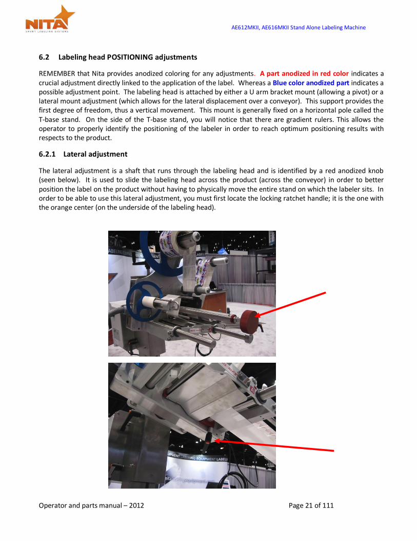
6.2.1 Lateral adjustment
The lateral adjustment is a shaft that runs through the labeling head and is identified by a red anodized knob (seen below). It is used to slide the labeling head across the product (across the conveyor) in order to better position the label on the product without having to physically move the entire stand on which the labeler sits. In order to be able to use this lateral adjustment, you must first locate the locking ratchet handle; it is the one with the orange center (on the underside of the labeling head).
AE612MKII, AE616MKII Stand Alone Labeling Machine
Operator and parts manual – 2012 Page 22 of 111
Pull on the handle to access the unlocking mechanism, turn it CCW to loosen. Turn the red anodized knob (lateral adjustment) CCW to move the labeler closer to you or CW to move further away from you. Use the ruler to obtain perfect positioning as per your requirements and save its value as a recipe setting in the HMI touch screen. (see the recipe section)
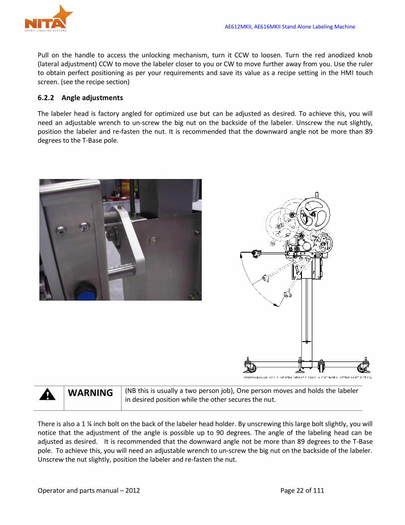
6.2.2 Angle adjustments
The labeler head is factory angled for optimized use but can be adjusted as desired. To achieve this, you will need an adjustable wrench to un-screw the big nut on the backside of the labeler. Unscrew the nut slightly, position the labeler and re-fasten the nut. It is recommended that the downward angle not be more than 89 degrees to the T-Base pole.
WARNING (NB this is usually a two person job), One person moves and holds the labeler
in desired position while the other secures the nut.
There is also a 1 ¼ inch bolt on the back of the labeler head holder. By unscrewing this large bolt slightly, you will notice that the adjustment of the angle is possible up to 90 degrees. The angle of the labeling head can be adjusted as desired. It is recommended that the downward angle not be more than 89 degrees to the T-Base pole. To achieve this, you will need an adjustable wrench to un-screw the big nut on the backside of the labeler. Unscrew the nut slightly, position the labeler and re-fasten the nut.

AE612MKII, AE616MKII Stand Alone Labeling Machine
Operator and parts manual – 2012 Page 23 of 111
A good adjustment is when the exit of the label is at a 15 to 20 degree angle against the surface of application.
6.2.3 Peel plate angle adjustments
The peel plate is also angle adjustable. Use the locking ratchet handle to loosen the peel plate, place the angle as desired and re-fasten it.
HINT: A good adjustment is when the exit of the label is at a 15 to 20 degree angle against the surface of application
AE612MKII, AE616MKII Stand Alone Labeling Machine
Operator and parts manual – 2012 Page 24 of 111
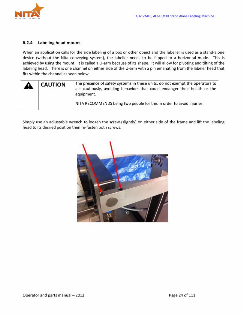
6.2.4 Labeling head mount
When an application calls for the side labeling of a box or other object and the labeller is used as a stand-alone device (without the Nita conveying system), the labeller needs to be flipped to a horizontal mode. This is achieved by using the mount. It is called a U-arm because of its shape. It will allow for pivoting and tilting of the labeling head. There is one channel on either side of the U-arm with a pin emanating from the labeler head that fits within the channel as seen below.
CAUTION The presence of safety systems in these units, do not exempt the operators to
act cautiously, avoiding behaviors that could endanger their health or the equipment.
NITA RECOMMENDS being two people for this in order to avoid injuries
Simply use an adjustable wrench to loosen the screw (slightly) on either side of the frame and lift the labeling head to its desired position then re-fasten both screws.
AE612MKII, AE616MKII Stand Alone Labeling Machine
Operator and parts manual – 2012 Page 25 of 111
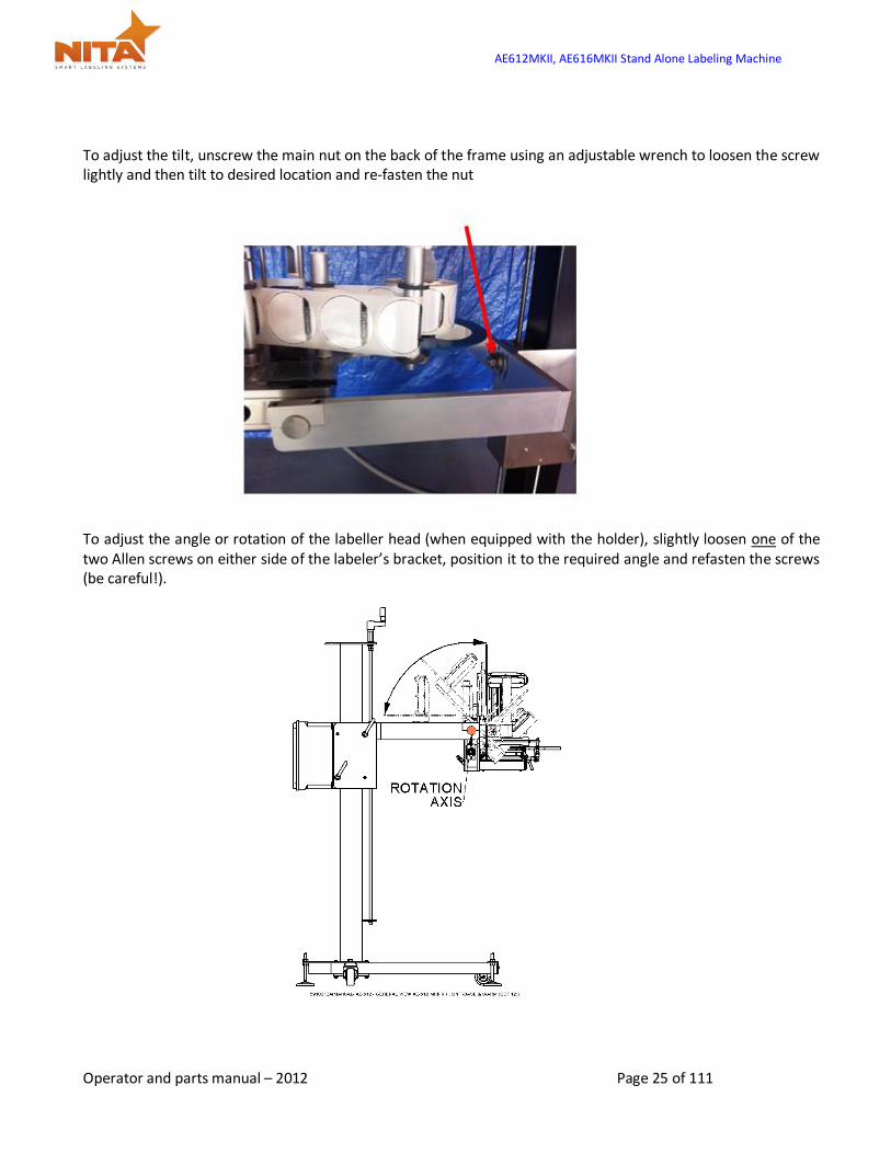
To adjust the tilt, unscrew the main nut on the back of the frame using an adjustable wrench to loosen the screw lightly and then tilt to desired location and re-fasten the nut
To adjust the angle or rotation of the labeller head (when equipped with the holder), slightly loosen one of the two Allen screws on either side of the labeler’s bracket, position it to the required angle and refasten the screws (be careful!).
AE612MKII, AE616MKII Stand Alone Labeling Machine
Operator and parts manual – 2012 Page 26 of 111
6.3 Loading & unloading the label stock roll
CAUTION To avoid injuries, you must keep the unit in MANUAL mode!
Look carefully at the diagram and follow the threading procedures indicated below.
You will also find the threading diagram directly on the Label applicator head as well as a quick reference
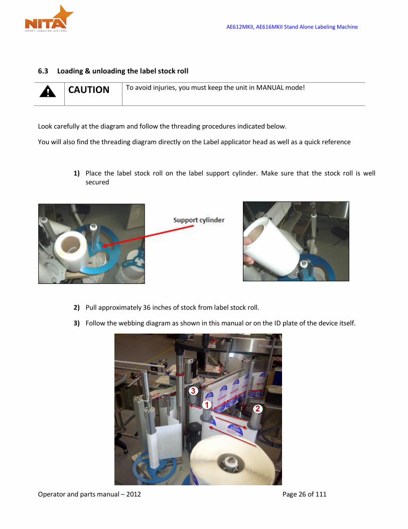
1) Place the label stock roll on the label support cylinder. Make sure that the stock roll is well secured
2) Pull approximately 36 inches of stock from label stock roll.
3) Follow the webbing diagram as shown in this manual or on the ID plate of the device itself.

AE612MKII, AE616MKII Stand Alone Labeling Machine
Operator and parts manual – 2012 Page 27 of 111
4) For different label widths, slide the guides on the rollers to avoid label swirling. Do not move the guides closest to the main plate, these are the zero point.
5) Release the spring-loaded tension plate by gently pulling the lock.
AE612MKII, AE616MKII Stand Alone Labeling Machine
Operator and parts manual – 2012 Page 28 of 111
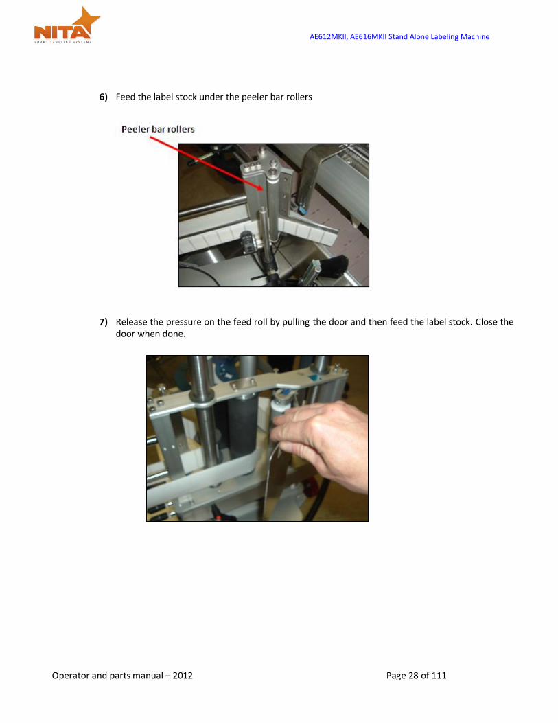
6) Feed the label stock under the peeler bar rollers
7) Release the pressure on the feed roll by pulling the door and then feed the label stock. Close the door when done.
AE612MKII, AE616MKII Stand Alone Labeling Machine
Operator and parts manual – 2012 Page 29 of 111
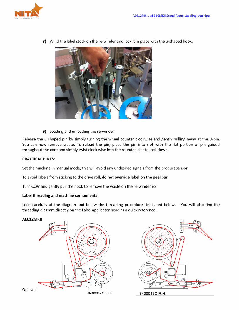
8) Wind the label stock on the re-winder and lock it in place with the u-shaped hook.
9) Loading and unloading the re-winder
Release the u shaped pin by simply turning the wheel counter clockwise and gently pulling away at the U-pin. You can now remove waste. To reload the pin, place the pin into slot with the flat portion of pin guided throughout the core and simply twist clock wise into the rounded slot to lock down.
PRACTICAL HINTS:
Set the machine in manual mode, this will avoid any undesired signals from the product sensor.
To avoid labels from sticking to the drive roll, do not override label on the peel bar.
Turn CCW and gently pull the hook to remove the waste on the re-winder roll
Label threading and machine components
Look carefully at the diagram and follow the threading procedures indicated below. You will also find the threading diagram directly on the Label applicator head as a quick reference.
AE612MKII

AE612MKII, AE616MKII Stand Alone Labeling Machine
Operator and parts manual – 2012 Page 30 of 111
AE616MKII
6.4 Connectivity and labeler head manual feed control button
On the side of the labeling head, you will find:
A manual feed button (which is also found on the HMI touch screen).
Two inputs are also present. One is for the gap sensor which detects the GAP between the labels and provides proper dispensing of labels. This may also be a sensor that can read black marks. The other input is for the product sensor.
AE612MKII, AE616MKII Stand Alone Labeling Machine
Operator and parts manual – 2012 Page 31 of 111
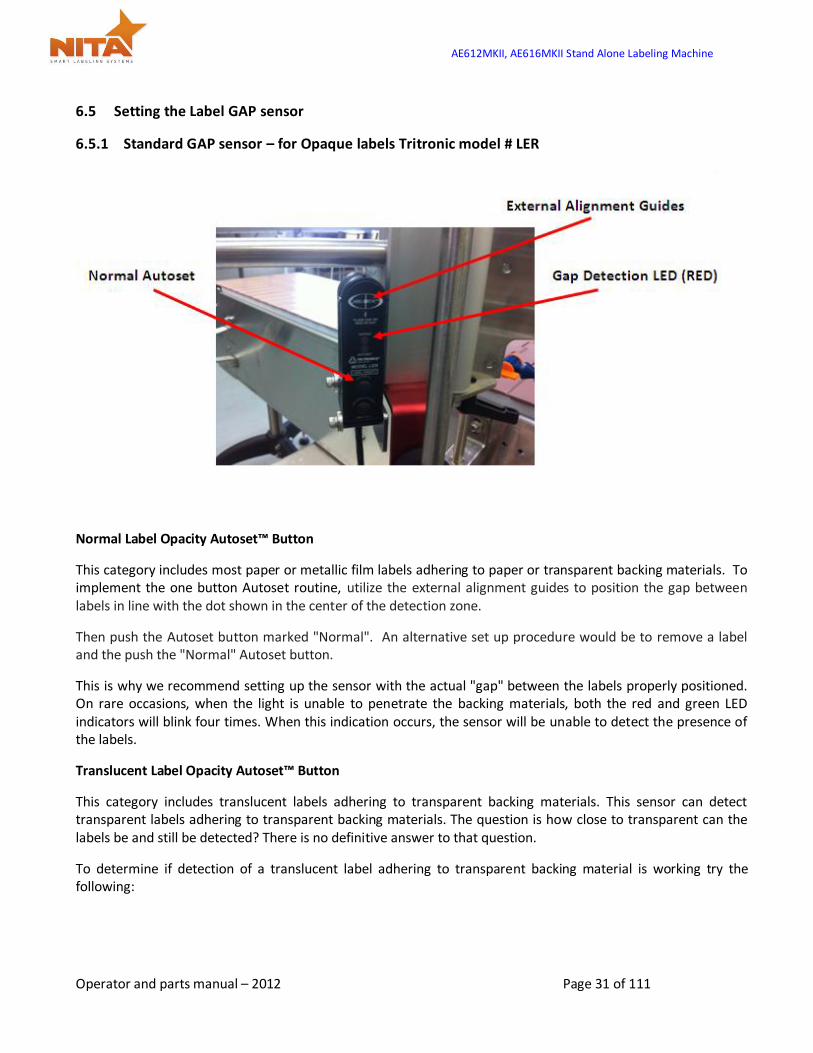
6.5 Setting the Label GAP sensor
6.5.1 Standard GAP sensor – for Opaque labels Tritronic model # LER
Normal Label Opacity Autoset™ Button
This category includes most paper or metallic film labels adhering to paper or transparent backing materials. To implement the one button Autoset routine, utilize the external alignment guides to position the gap between labels in line with the dot shown in the center of the detection zone.
Then push the Autoset button marked "Normal". An alternative set up procedure would be to remove a label and the push the "Normal" Autoset button.
This is why we recommend setting up the sensor with the actual "gap" between the labels properly positioned. On rare occasions, when the light is unable to penetrate the backing materials, both the red and green LED indicators will blink four times. When this indication occurs, the sensor will be unable to detect the presence of the labels.
Translucent Label Opacity Autoset™ Button
This category includes translucent labels adhering to transparent backing materials. This sensor can detect transparent labels adhering to transparent backing materials. The question is how close to transparent can the labels be and still be detected? There is no definitive answer to that question.
To determine if detection of a translucent label adhering to transparent backing material is working try the following:
AE612MKII, AE616MKII Stand Alone Labeling Machine
Operator and parts manual – 2012 Page 32 of 111
Autoset procedure: First utilize the external alignment guides to position the gap between labels in line with the dot shown in the center of the detection zone. Then, push the Autoset button marked "Translucent". The next step is to move the web so that the translucent label goes in and out of the light beam. If detection is possible, the red LED output indicator should go on when the label passes through the detection zone.
INVERT OUTPUT: The status of the red LED and output transistors can be inverted by pressing both buttons simultaneously. When the output status has been inverted, the red LED and the output transistors will turn off when the label comes into view.
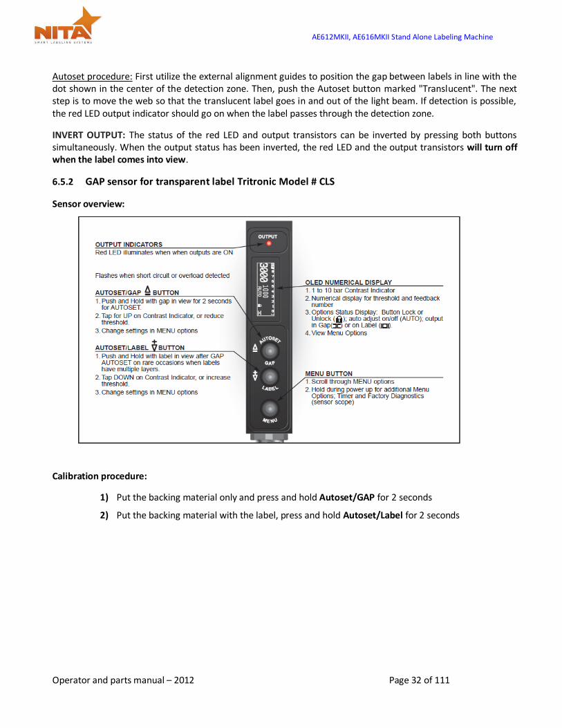
6.5.2 GAP sensor for transparent label Tritronic Model # CLS
Sensor overview:
Calibration procedure:
1) Put the backing material only and press and hold Autoset/GAP for 2 seconds
2) Put the backing material with the label, press and hold Autoset/Label for 2 seconds
AE612MKII, AE616MKII Stand Alone Labeling Machine
Operator and parts manual – 2012 Page 33 of 111
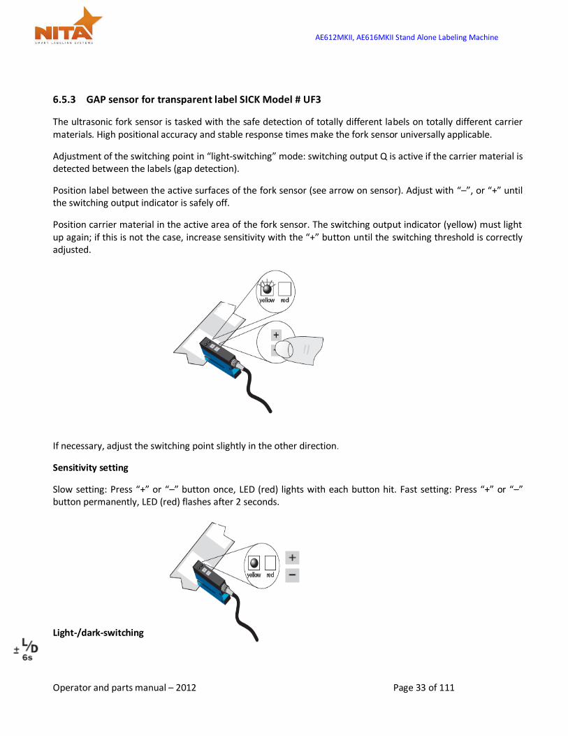
6.5.3 GAP sensor for transparent label SICK Model # UF3
The ultrasonic fork sensor is tasked with the safe detection of totally different labels on totally different carrier materials. High positional accuracy and stable response times make the fork sensor universally applicable.
Adjustment of the switching point in “light-switching” mode: switching output Q is active if the carrier material is detected between the labels (gap detection).
Position label between the active surfaces of the fork sensor (see arrow on sensor). Adjust with “–”‚ or “+” until the switching output indicator is safely off.
Position carrier material in the active area of the fork sensor. The switching output indicator (yellow) must light up again; if this is not the case, increase sensitivity with the “+” button until the switching threshold is correctly adjusted.
If necessary, adjust the switching point slightly in the other direction.
Sensitivity setting
Slow setting: Press “+” or “–” button once, LED (red) lights with each button hit. Fast setting: Press “+” or “–” button permanently, LED (red) flashes after 2 seconds.
Light-/dark-switching
AE612MKII, AE616MKII Stand Alone Labeling Machine
Operator and parts manual – 2012 Page 34 of 111
Press “+” and “–” buttons simultaneously for 6 seconds, LED (yellow) changes status, and the LED (red) flashes slowly. Release “+” and “–” buttons.
Locking the buttons
Press “+” and “–” buttons simultaneously for 3 seconds, button lock is enabled/disabled. Locking the buttons: The red LED goes off after 3 seconds, release “+” and “–” buttons, LED (red) lights permanently. Unlocking the buttons. The red LED lights after 3 seconds, release “+” and “–” buttons, LED (red) extinguishes.
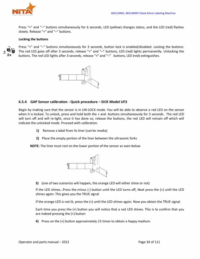
6.5.4 GAP Sensor calibration - Quick procedure – SICK Model UF3
Begin by making sure that the sensor is in UN-LOCK mode. You will be able to observe a red LED on the sensor when it is locked. To unlock, press and hold both the + and -buttons simultaneously for 3 seconds. The red LED will turn off and will re-light, once it has done so, release the buttons, the red LED will remain off which will indicate the unlocked mode. Proceed with calibration.
1) Remove a label from its liner (carrier media)
2) Place the empty portion of the liner between the ultrasonic forks
NOTE: The liner must rest on the lower portion of the sensor as seen below
3) (one of two scenarios will happen, the orange LED will either shine or not)
If the LED shines…Press the minus (-) button until the LED turns off, Next press the (+) until the LED shines again. This gives you the TRUE signal
If the orange LED is not lit, press the (+) until the LED shines again. Now you obtain the TRUE signal.
Each time you press the (+) button you will notice that a red LED shines. This is to confirm that you are indeed pressing the (+) button
4) Press on the (+) button approximately 15 times to obtain a happy medium.

AE612MKII, AE616MKII Stand Alone Labeling Machine
Operator and parts manual – 2012 Page 35 of 111
You can verify the calibration by manually showing the liner with the label to the sensor as seen above. When it is calibrated properly you will see the orange LED light illuminate when the sensor passes over the GAP section.
6.5.5 GAP sensor calibration - CLEAR label - Quick procedure Di-Soric Model # KSSTI 1000 (Capacitive - Black)
1) Press teach key and hold for 2 sec.
2) The LED on the sensor will flashes
3) Pull the label thru to the slit of gap sensor and pass at least 2 labels.

AE612MKII, AE616MKII Stand Alone Labeling Machine
Operator and parts manual – 2012 Page 36 of 111
6.6 Product sensors
The product sensors are each connected to the electrical box via the input slot. Ideally when installed on the bracket correctly, the sensitivity of the optical beam is reflecting off the reflector. Too sensitive and the sensor will not reach the reflector.
To ensure that the proper sensitivity is obtained:
Make sure that the sensor beam is aligned with the reflector on its opposite side of the product.
5) To adjust, use the sensitivity adjustment to control the detection distance of your beam. Turn the adjustment (CCW) (see drawing) until the LED turns off.
6) Turn the adjustment (CW) slowly until the LED lights up again.
7) Continue turning CW for an additional ½ turn.
8) Check the calibration by simply placing your hand between the reflector and the sensor. The beam should be broken and the LED light should turn off. If this is the case, the sensor adjustment is set.
HINT: By hand, allow the product (empty in the case of a clamshell) resting on the conveyor to pass in front of the sensor reflector at a low speed and confirm that the sensor LED stays off all through the passage of the clamshell.
AE612MKII, AE616MKII Stand Alone Labeling Machine
Operator and parts manual – 2012 Page 37 of 111
7 HMI – Getting to know the HMI touch screen – Operator interface
What you need to know about the HMI (human machine interface)
PLEASE READ CAREFULLY
The HMI operator interface allows you to:
Adjust your equipment for various products, (speeds, gradient ruler positions, etc…)
Get feedback about the process as well as the problems incurred
Get a global control of the equipment.
It is a smart interface that allows you to touch the screen for you to change the parameters without the use of a computer. There are many small menus or windows that allow the system to run more efficiently. Some screens or menus require a password in order to allow only authorized personnel to change parameters. The initial password for the operator to begin using the HMI immediately is 12345678. Here then is an outlook of the screens, an explanation for each and their roles.
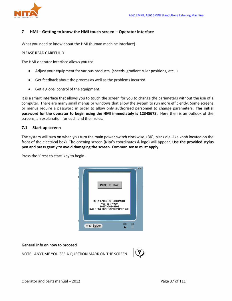
7.1 Start up screen
The system will turn on when you turn the main power switch clockwise. (BIG, black dial-like knob located on the front of the electrical box). The opening screen (Nita’s coordinates & logo) will appear. Use the provided stylus pen and press gently to avoid damaging the screen. Common sense must apply.
Press the ‘Press to start’ key to begin.
General info on how to proceed
NOTE: ANYTIME YOU SEE A QUESTION MARK ON THE SCREEN
AE612MKII, AE616MKII Stand Alone Labeling Machine
Operator and parts manual – 2012 Page 38 of 111
The question mark (?) keys lead to a ‘help’ screen which provides a brief explanation or tips on the adjustment method of the specific setting. This helps to minimize the time taken to make adjustments.
The different functions on all the screens are activated by a simple touch of the keys on the screen. Almost each screen has these keys. Press either to navigate from screen to screen
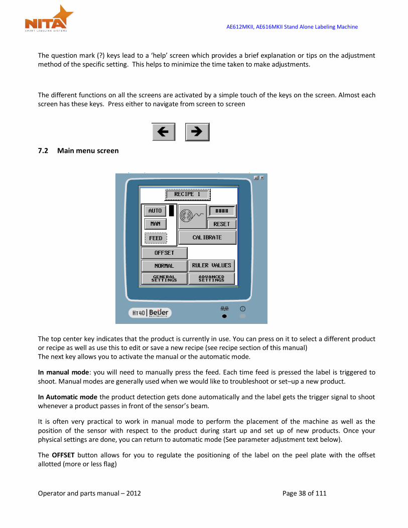
7.2 Main menu screen
The top center key indicates that the product is currently in use. You can press on it to select a different product or recipe as well as use this to edit or save a new recipe (see recipe section of this manual) The next key allows you to activate the manual or the automatic mode.
In manual mode: you will need to manually press the feed. Each time feed is pressed the label is triggered to shoot. Manual modes are generally used when we would like to troubleshoot or set–up a new product.
In Automatic mode the product detection gets done automatically and the label gets the trigger signal to shoot whenever a product passes in front of the sensor’s beam.
It is often very practical to work in manual mode to perform the placement of the machine as well as the position of the sensor with respect to the product during start up and set up of new products. Once your physical settings are done, you can return to automatic mode (See parameter adjustment text below).
The OFFSET button allows for you to regulate the positioning of the label on the peel plate with the offset allotted (more or less flag)

AE612MKII, AE616MKII Stand Alone Labeling Machine
Operator and parts manual – 2012 Page 39 of 111
NORMAL / 3 Panel: allows the selection from tri-panel to normal mode. Here is the difference between the two modes
General settings: for adjustment of time, language, passwords, screen brightness, contrast.
Advanced setting: internal parameters for the system must only be changed or modified by qualified technicians. These are password protected
Ruler values will indicate the values of your gradient scales setting as entered for each product recipe. This optimizes set up and saves time.
Calibrate: allows for the label to always end at the peel plates edge. You will need to press “calibrate” after each roll change or after an alarm.
Reset initialises the counter to zero
Normal mode 3-panel mode
AE612MKII, AE616MKII Stand Alone Labeling Machine
Operator and parts manual – 2012 Page 40 of 111
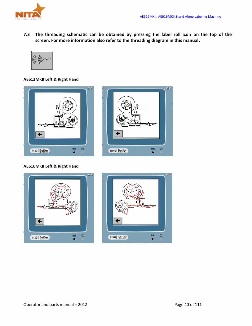
7.3 The threading schematic can be obtained by pressing the label roll icon on the top of the screen. For more information also refer to the threading diagram in this manual.
AE612MKII Left & Right Hand
AE616MKII Left & Right Hand
AE612MKII, AE616MKII Stand Alone Labeling Machine
Operator and parts manual – 2012 Page 41 of 111
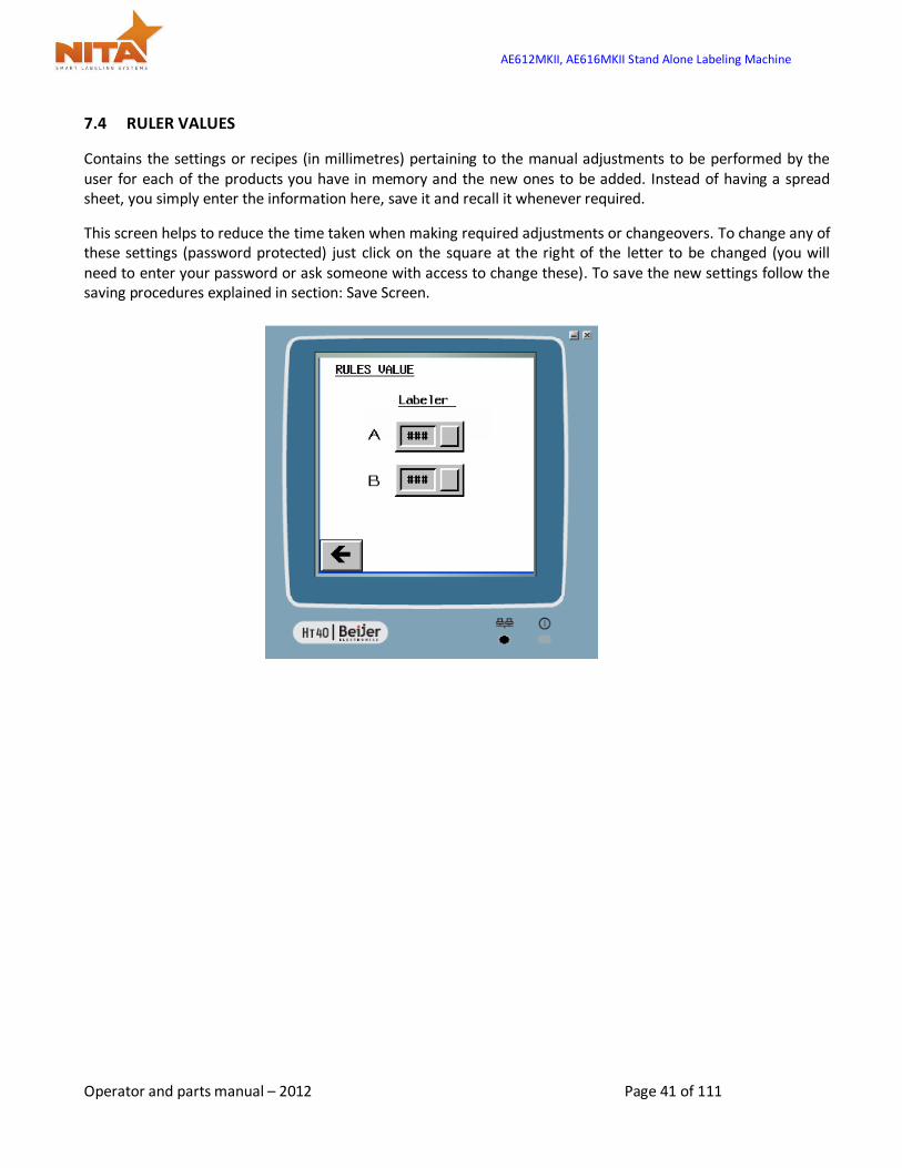
7.4 RULER VALUES
Contains the settings or recipes (in millimetres) pertaining to the manual adjustments to be performed by the user for each of the products you have in memory and the new ones to be added. Instead of having a spread sheet, you simply enter the information here, save it and recall it whenever required.
This screen helps to reduce the time taken when making required adjustments or changeovers. To change any of these settings (password protected) just click on the square at the right of the letter to be changed (you will need to enter your password or ask someone with access to change these). To save the new settings follow the saving procedures explained in section: Save Screen.
AE612MKII, AE616MKII Stand Alone Labeling Machine
Operator and parts manual – 2012 Page 42 of 111
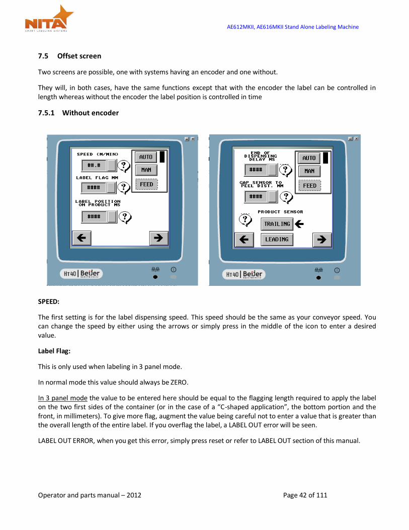
7.5 Offset screen
Two screens are possible, one with systems having an encoder and one without.
They will, in both cases, have the same functions except that with the encoder the label can be controlled in length whereas without the encoder the label position is controlled in time
7.5.1 Without encoder
SPEED:
The first setting is for the label dispensing speed. This speed should be the same as your conveyor speed. You can change the speed by either using the arrows or simply press in the middle of the icon to enter a desired value.
Label Flag:
This is only used when labeling in 3 panel mode.
In normal mode this value should always be ZERO.
In 3 panel mode the value to be entered here should be equal to the flagging length required to apply the label on the two first sides of the container (or in the case of a “C-shaped application”, the bottom portion and the front, in millimeters). To give more flag, augment the value being careful not to enter a value that is greater than the overall length of the entire label. If you overflag the label, a LABEL OUT error will be seen.
LABEL OUT ERROR, when you get this error, simply press reset or refer to LABEL OUT section of this manual.
AE612MKII, AE616MKII Stand Alone Labeling Machine
Operator and parts manual – 2012 Page 43 of 111
Label position on product:
This is measured in time. This value should reflect the time elapsed between the moment where the product is detected by the product sensor and the moment where the label begins its application feed. Never moving the sensor AGAIN, this setting will allow the product to always be positioned in the same location on the product when you recall the recipe from memory at a later time.
It is recommended to keep the product sensor as close as possible to the peel plate and to never to move it again to avoid label positioning errors. The arrow pointing to the next screen will allow for adjustments in 3 panel mode where you will be able to enter the end of dispensing time delay.
This screen has 2 possible settings.
End of dispensing delay in MS (milliseconds):
This is for the flagging of the next label after the first one has been dispensed. The lower this value, the faster your throughput will be. BUT this delay must be long enough to allow the container to fully pass through the label application zone before a next label is fed.
HINT: if you are getting 2 labels on the same container, this value needs to be higher.
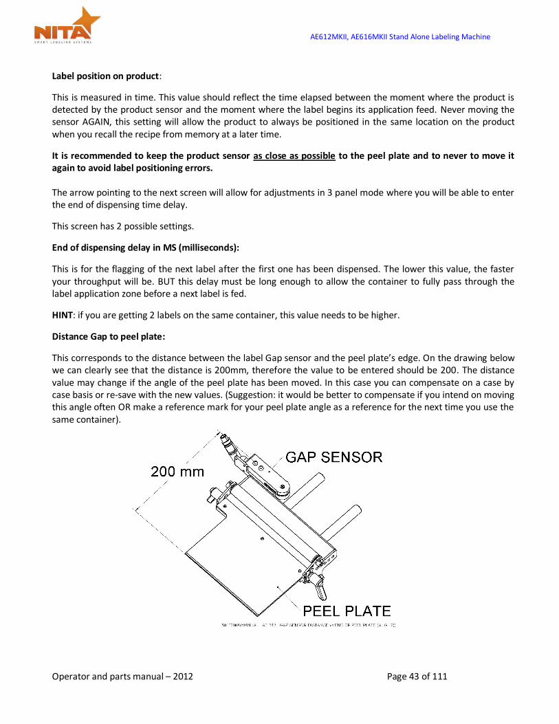
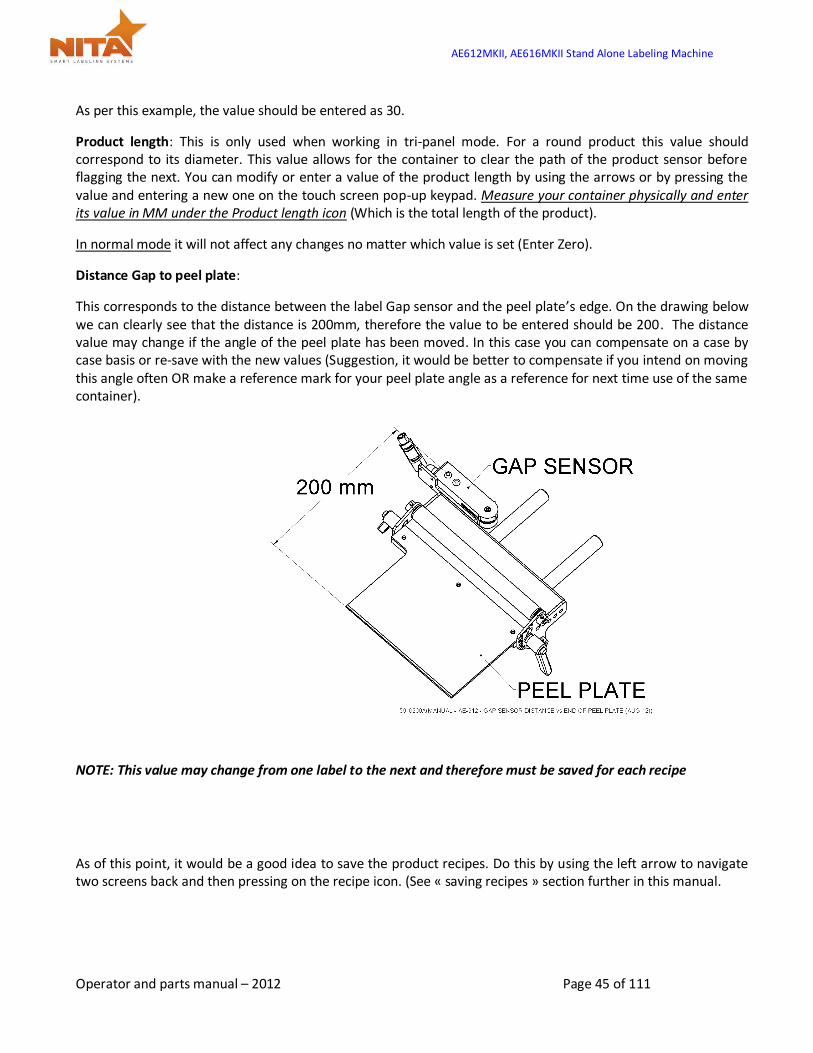
Distance Gap to peel plate:
This corresponds to the distance between the label Gap sensor and the peel plate’s edge. On the drawing below we can clearly see that the distance is 200mm, therefore the value to be entered should be 200. The distance value may change if the angle of the peel plate has been moved. In this case you can compensate on a case by case basis or re-save with the new values. (Suggestion: it would be better to compensate if you intend on moving this angle often OR make a reference mark for your peel plate angle as a reference for the next time you use the same container).
AE612MKII, AE616MKII Stand Alone Labeling Machine
Operator and parts manual – 2012 Page 44 of 111
NOTE: This value may change from one label to the next and therefore must be saved for each recipe
As of this point, it would be a good idea to save the product recipes. Do this by using the left arrow to navigate two screens back and then pressing on the recipe icon. (See « saving recipes » section further in this manual.
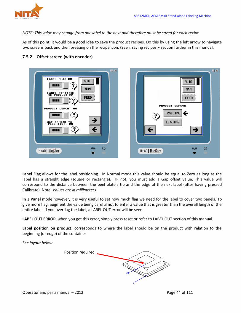
7.5.2 Offset screen (with encoder)
Label Flag allows for the label positioning. In Normal mode this value should be equal to Zero as long as the label has a straight edge (square or rectangle). IF not, you must add a Gap offset value. This value will correspond to the distance between the peel plate’s tip and the edge of the next label (after having pressed Calibrate). Note: Values are in millimeters.
In 3 Panel mode however, it is very useful to set how much flag we need for the label to cover two panels. To give more flag, augment the value being careful not to enter a value that is greater than the overall length of the entire label. If you overflag the label, a LABEL OUT error will be seen.
LABEL OUT ERROR, when you get this error, simply press reset or refer to LABEL OUT section of this manual.
Label position on product: corresponds to where the label should be on the product with relation to the beginning (or edge) of the container
See layout below
Position required
AE612MKII, AE616MKII Stand Alone Labeling Machine
Operator and parts manual – 2012 Page 45 of 111
As per this example, the value should be entered as 30.
Product length: This is only used when working in tri-panel mode. For a round product this value should correspond to its diameter. This value allows for the container to clear the path of the product sensor before flagging the next. You can modify or enter a value of the product length by using the arrows or by pressing the value and entering a new one on the touch screen pop-up keypad. Measure your container physically and enter its value in MM under the Product length icon (Which is the total length of the product).
In normal mode it will not affect any changes no matter which value is set (Enter Zero).
Distance Gap to peel plate:
This corresponds to the distance between the label Gap sensor and the peel plate’s edge. On the drawing below we can clearly see that the distance is 200mm, therefore the value to be entered should be 200. The distance value may change if the angle of the peel plate has been moved. In this case you can compensate on a case by case basis or re-save with the new values (Suggestion, it would be better to compensate if you intend on moving this angle often OR make a reference mark for your peel plate angle as a reference for next time use of the same container).
NOTE: This value may change from one label to the next and therefore must be saved for each recipe
As of this point, it would be a good idea to save the product recipes. Do this by using the left arrow to navigate two screens back and then pressing on the recipe icon. (See « saving recipes » section further in this manual.
AE612MKII, AE616MKII Stand Alone Labeling Machine
Operator and parts manual – 2012 Page 46 of 111
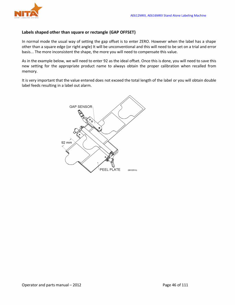
Labels shaped other than square or rectangle (GAP OFFSET)
In normal mode the usual way of setting the gap offset is to enter ZERO. However when the label has a shape other than a square edge (or right angle) It will be unconventional and this will need to be set on a trial and error basis... The more inconsistent the shape, the more you will need to compensate this value.
As in the example below, we will need to enter 92 as the ideal offset. Once this is done, you will need to save this new setting for the appropriate product name to always obtain the proper calibration when recalled from memory.
It is very important that the value entered does not exceed the total length of the label or you will obtain double label feeds resulting in a label out alarm.

AE612MKII, AE616MKII Stand Alone Labeling Machine
Operator and parts manual – 2012 Page 47 of 111
7.6 General settings screen
These screens will allow the access to settings like the changing language displayed, contrast of the screen, and the setting of time and date. Simply navigate from one screen to the next using the arrows.
The other screens give access to the setting directly
AE612MKII, AE616MKII Stand Alone Labeling Machine
Operator and parts manual – 2012 Page 48 of 111
7.7 Advanced settings
From the main screen, you can reach the Advanced Settings screen that greatly affects the parameters of the entire system. Therefore, they are password protected to avoid changes made by error. These have been entered by Nita and should not be accessed unless authorized by manufacturer. Qualified technicians can use this screen to help with troubleshooting.
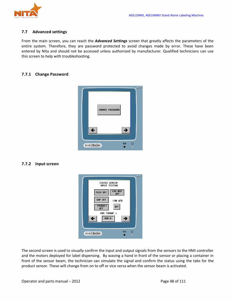
7.7.1 Change Password
7.7.2 Input screen
The second screen is used to visually confirm the input and output signals from the sensors to the HMI controller and the motors deployed for label dispensing. By waving a hand in front of the sensor or placing a container in front of the sensor beam, the technician can simulate the signal and confirm the status using the tabs for the product sensor. These will change from on to off or vice versa when the sensor beam is activated.
AE612MKII, AE616MKII Stand Alone Labeling Machine
Operator and parts manual – 2012 Page 49 of 111
For the Gap sensor, this can also be simulated by unlocking the label tension plate and slowly pulling on the line to the next gap or moving the existing gap back and forth under the sensor.
The Feed button will allow you to see the variance from off to on, when the motor turns into motion to feed the label.
The RMS Torque % allows for the adjustment of the tension plate (on the output of the labeler) with respect to the torque deployed. These settings are done at the factory.
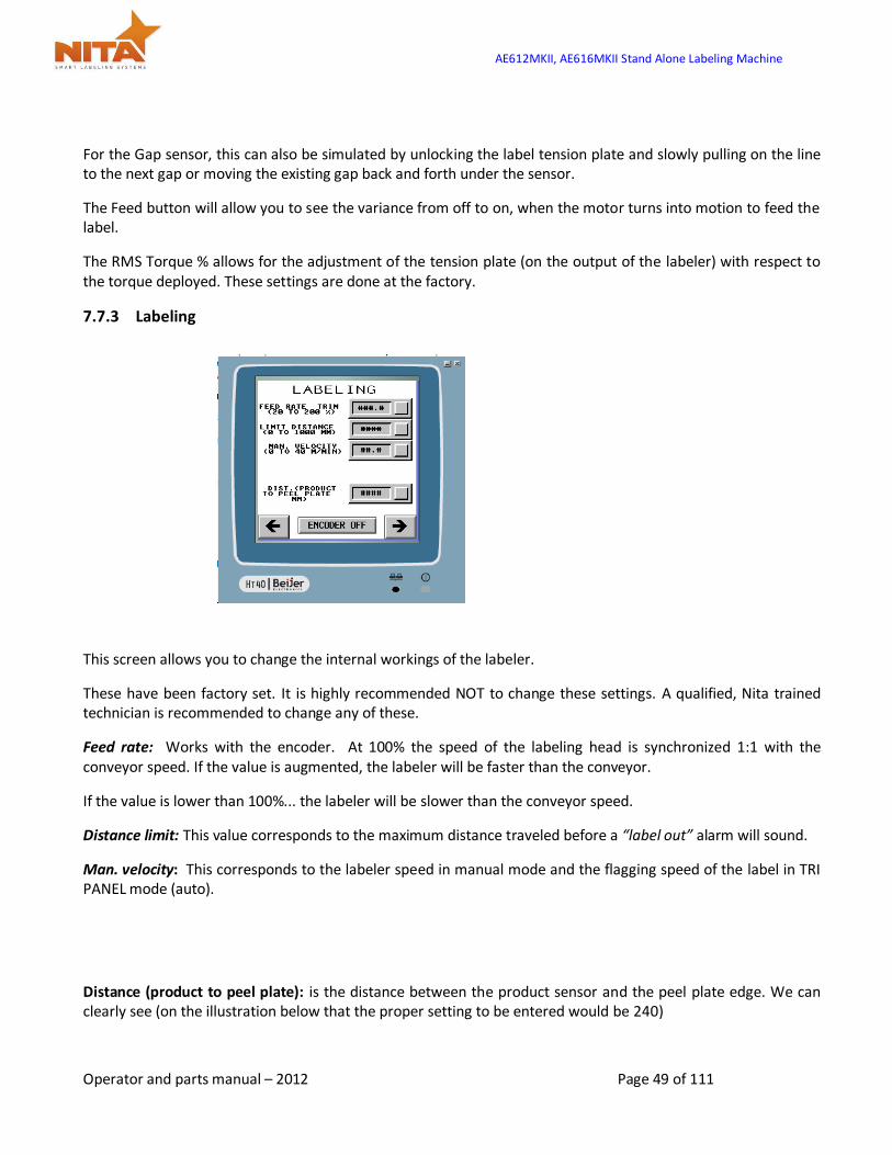
7.7.3 Labeling
This screen allows you to change the internal workings of the labeler.
These have been factory set. It is highly recommended NOT to change these settings. A qualified, Nita trained technician is recommended to change any of these.
Feed rate: Works with the encoder. At 100% the speed of the labeling head is synchronized 1:1 with the conveyor speed. If the value is augmented, the labeler will be faster than the conveyor.
If the value is lower than 100%... the labeler will be slower than the conveyor speed.
Distance limit: This value corresponds to the maximum distance traveled before a “label out” alarm will sound.
Man. velocity: This corresponds to the labeler speed in manual mode and the flagging speed of the label in TRI PANEL mode (auto).
Distance (product to peel plate): is the distance between the product sensor and the peel plate edge. We can clearly see (on the illustration below that the proper setting to be entered would be 240)

AE612MKII, AE616MKII Stand Alone Labeling Machine
Operator and parts manual – 2012 Page 50 of 111
This will have no influence if your system DOES NOT has an encoder.
7.7.4 Servo motor rotation direction Screen
The direction of rotation is changeable from clockwise to counter clockwise (LH or RH).
AE612MKII, AE616MKII Stand Alone Labeling Machine
Operator and parts manual – 2012 Page 51 of 111
This adjustment is only necessary once and it is factory set.
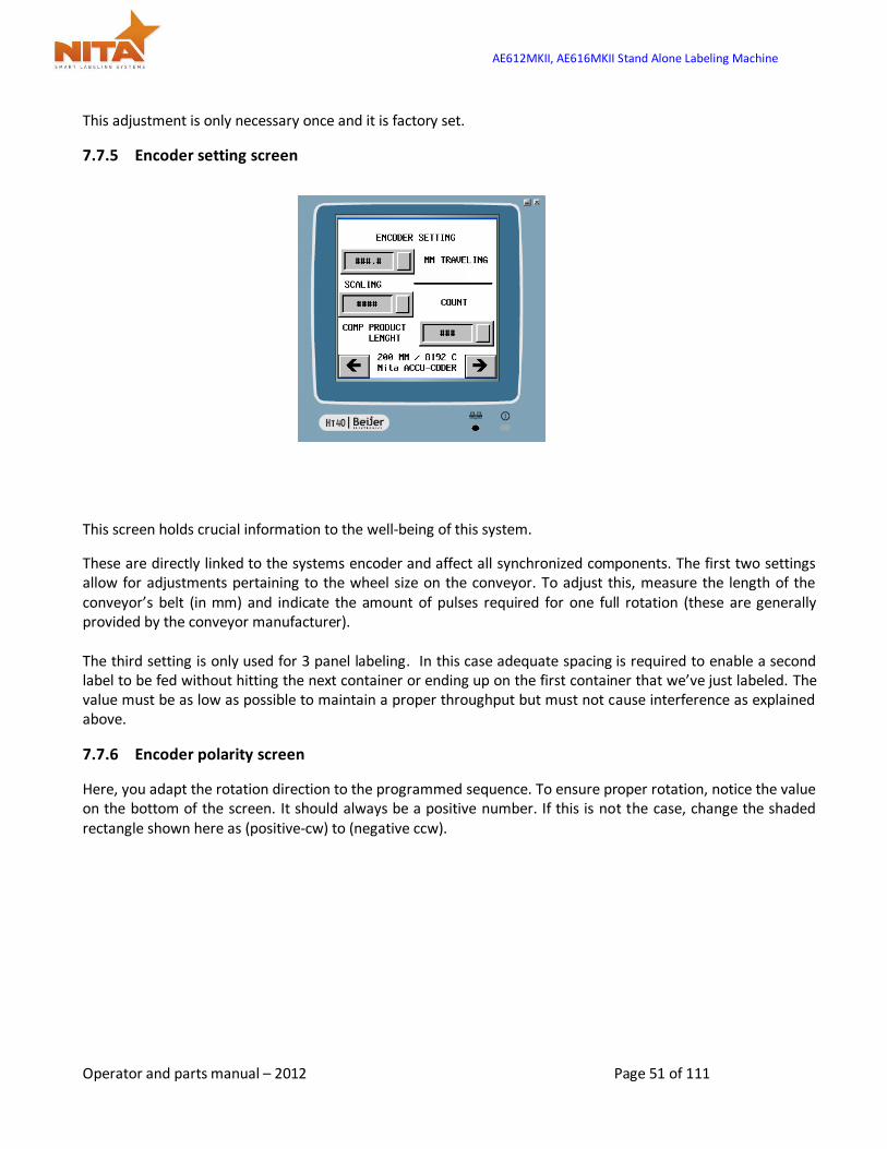
7.7.5 Encoder setting screen
This screen holds crucial information to the well-being of this system.
These are directly linked to the systems encoder and affect all synchronized components. The first two settings allow for adjustments pertaining to the wheel size on the conveyor. To adjust this, measure the length of the conveyor’s belt (in mm) and indicate the amount of pulses required for one full rotation (these are generally provided by the conveyor manufacturer). The third setting is only used for 3 panel labeling. In this case adequate spacing is required to enable a second label to be fed without hitting the next container or ending up on the first container that we’ve just labeled. The value must be as low as possible to maintain a proper throughput but must not cause interference as explained above.
7.7.6 Encoder polarity screen
Here, you adapt the rotation direction to the programmed sequence. To ensure proper rotation, notice the value on the bottom of the screen. It should always be a positive number. If this is not the case, change the shaded rectangle shown here as (positive-cw) to (negative ccw).

AE612MKII, AE616MKII Stand Alone Labeling Machine
Operator and parts manual – 2012 Page 52 of 111
7.8 Calibrate screen
When an abnormal label feed is done, an error signal is sent to trigger the following screen. It is highly recommended that the threading be counter-verified as well as the GAP sensor checked to make sure that everything is adequate.
Following the verifications, press calibrate so that the system will take into consideration the labels and their positions.
If you feel that this screen has been obtained by mistake, press the arrow icon to return to previous screen
AE612MKII, AE616MKII Stand Alone Labeling Machine
Operator and parts manual – 2012 Page 53 of 111
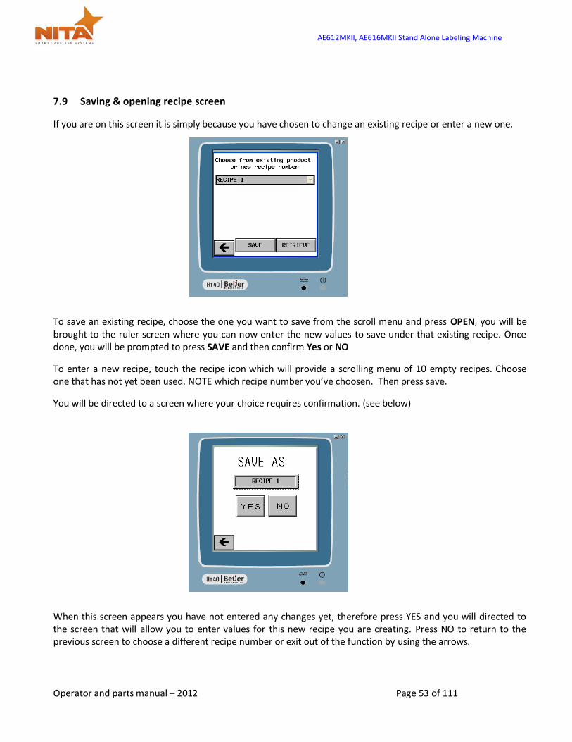
7.9 Saving & opening recipe screen
If you are on this screen it is simply because you have chosen to change an existing recipe or enter a new one.
To save an existing recipe, choose the one you want to save from the scroll menu and press OPEN, you will be brought to the ruler screen where you can now enter the new values to save under that existing recipe. Once done, you will be prompted to press SAVE and then confirm Yes or NO
To enter a new recipe, touch the recipe icon which will provide a scrolling menu of 10 empty recipes. Choose one that has not yet been used. NOTE which recipe number you’ve choosen. Then press save.
You will be directed to a screen where your choice requires confirmation. (see below)
When this screen appears you have not entered any changes yet, therefore press YES and you will directed to the screen that will allow you to enter values for this new recipe you are creating. Press NO to return to the previous screen to choose a different recipe number or exit out of the function by using the arrows.

AE612MKII, AE616MKII Stand Alone Labeling Machine
Operator and parts manual – 2012 Page 54 of 111
7.9.1 The Help screens
Each time that an icon with a QUESTION MARK is available, you can obtain hints and explanation about the setting. Simply press the icon with the « ? ». See General info on how to proceed at the beginning of the HMI section.
These screens will appear when you press on this key:
Here are examples of screens which will guide you to perform the right adjustments. They will indicate how to adjust the various settings in the most effective way possible and provide hints.
7.10 Alarm screen
This screen appears when a problem with labeling the containers occurs. As you can see it will indicate which labeling head the problem came from (In this example the back labeler is at fault). An audible alarm will also sound at the same time as this message is displayed.

AE612MKII, AE616MKII Stand Alone Labeling Machine
Operator and parts manual – 2012 Page 55 of 111
To reactivate the system, after solving the problem, simply press the Reset key. It will lead you to the screen of the faulty labeling head and will stop the audible alarm. You will have to reposition the web (or tend to empty roll) and restart the system.
AE612MKII, AE616MKII Stand Alone Labeling Machine
Operator and parts manual – 2012 Page 56 of 111
8 MAINTENANCE
This machine has been designed with the minimal maintenance requirement possible. There are however some things to take into consideration.
After every 100 hours of operation, a visual inspection of the system should be done and where it is necessary, lubrication and cleaning should be performed.
CAUTION WEAR PROTECTIVE EYEWEAR when performing any maintenance on this
equipment
CAUTION To reduce risk of fire, electrocution or other personal injury when operating
or maintaining the labeling head, follow basic safety precaution, including the following:
Maintaining the labeling head, follow basic safety precaution, including the following:
DO NOT perform any servicing or maintenance with the Power ON.
Always disconnect the electrical plug from wall socket
Make sure that the power is OFF or that available E-stop buttons have been activated
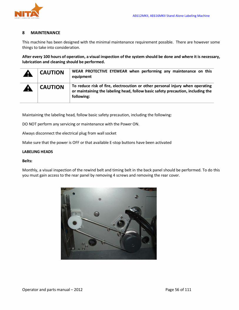
LABELING HEADS
Belts:
Monthly, a visual inspection of the rewind belt and timing belt in the back panel should be performed. To do this you must gain access to the rear panel by removing 4 screws and removing the rear cover.

AE612MKII, AE616MKII Stand Alone Labeling Machine
Operator and parts manual – 2012 Page 57 of 111
CAUTION DO NOT ATTEMPT doing this with the equipment under tension (with power
on).
The visual inspection should consist of looking for cracks or defects in the belts. If this is the case, change the belts that are defective. Refer to the parts listing at the back of this manual (parts section)
The braking mechanism requires a monthly visual inspection as well. Also once every 12 months or so you should consider replacing the belt (it is possible that this belt will need to be changed prior to the 12 month time frame therefore a visual inspection to determine if there are cracks or tears in the belt is necessary). This leather brake belt is located at the rear of the media wheel and is held by a spring & hock assembly. These components are all part of the recommended spare parts kit and are listed at the beginning of this manual.
Rollers: It is important that your labeler be as clean as possible in its environment in order for it to perform properly. Daily, you may want to clean all the rollers including the drive roller (the rubber one), the tension door and the peel plate using a damp cloth with alcohol. Make sure those parts have no glue or labels on it.
AE612MKII, AE616MKII Stand Alone Labeling Machine
Operator and parts manual – 2012 Page 58 of 111
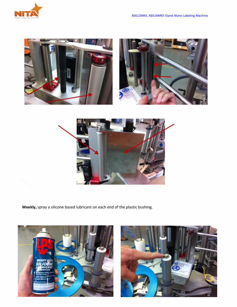
Weekly, spray a silicone based lubricant on each end of the plastic bushing.
AE612MKII, AE616MKII Stand Alone Labeling Machine
Operator and parts manual – 2012 Page 59 of 111
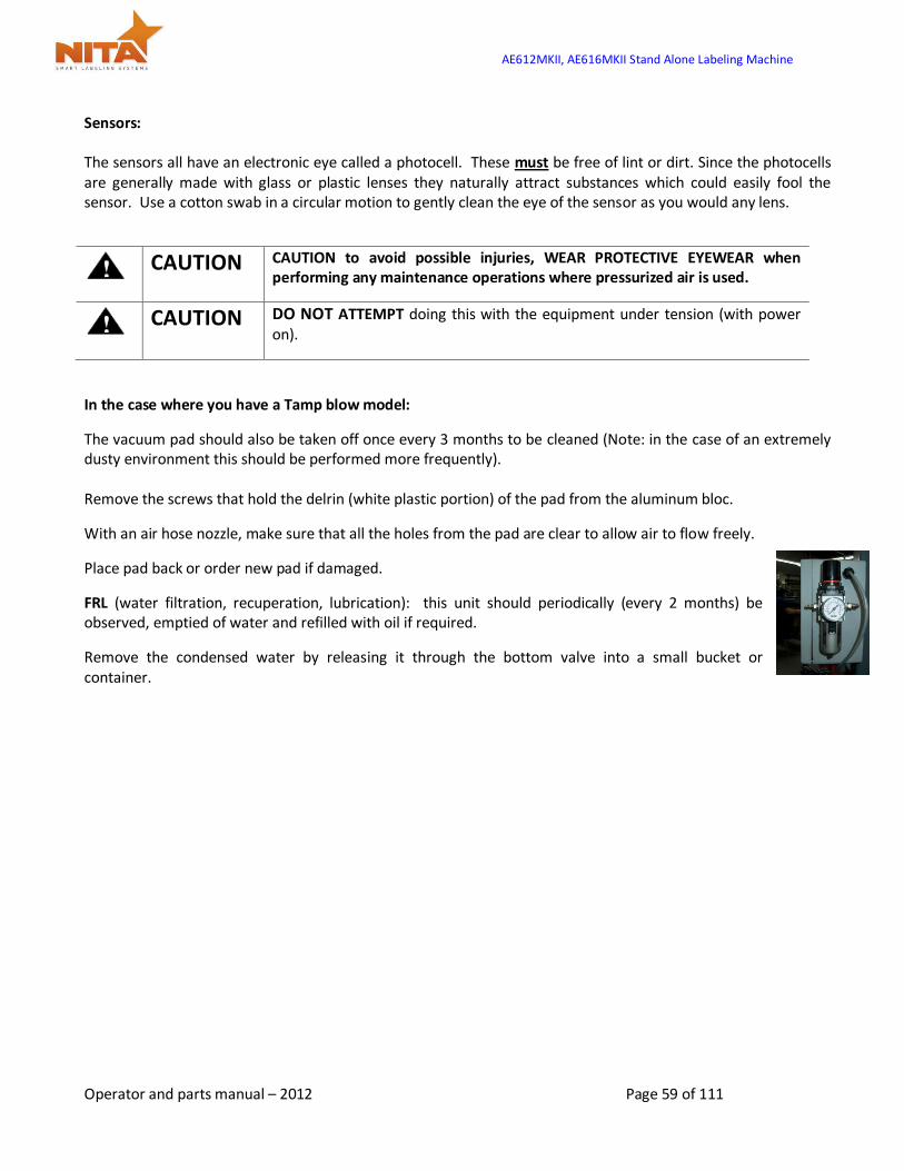
Sensors: The sensors all have an electronic eye called a photocell. These must be free of lint or dirt. Since the photocells are generally made with glass or plastic lenses they naturally attract substances which could easily fool the sensor. Use a cotton swab in a circular motion to gently clean the eye of the sensor as you would any lens.
CAUTION CAUTION to avoid possible injuries, WEAR PROTECTIVE EYEWEAR when
performing any maintenance operations where pressurized air is used.
CAUTION DO NOT ATTEMPT doing this with the equipment under tension (with power
on).
In the case where you have a Tamp blow model:
The vacuum pad should also be taken off once every 3 months to be cleaned (Note: in the case of an extremely dusty environment this should be performed more frequently). Remove the screws that hold the delrin (white plastic portion) of the pad from the aluminum bloc.
With an air hose nozzle, make sure that all the holes from the pad are clear to allow air to flow freely.
Place pad back or order new pad if damaged.
FRL (water filtration, recuperation, lubrication): this unit should periodically (every 2 months) be observed, emptied of water and refilled with oil if required.
Remove the condensed water by releasing it through the bottom valve into a small bucket or container.
AE612MKII, AE616MKII Stand Alone Labeling Machine
Operator and parts manual – 2012 Page 60 of 111
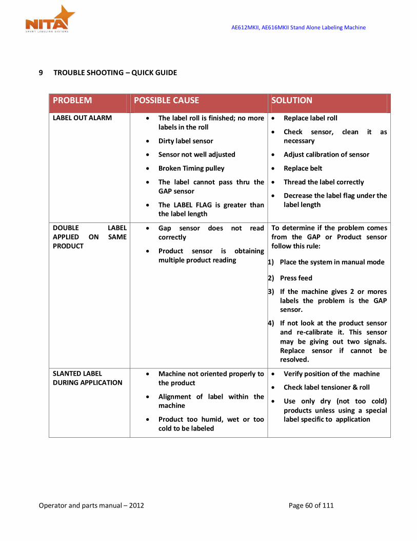
9 TROUBLE SHOOTING – QUICK GUIDE
PROBLEM POSSIBLE CAUSE SOLUTION
LABEL OUT ALARM The label roll is finished; no more labels in the roll
Dirty label sensor
Sensor not well adjusted
Broken Timing pulley
The label cannot pass thru the GAP sensor
The LABEL FLAG is greater than the label length
Replace label roll
Check sensor, clean it as necessary
Adjust calibration of sensor
Replace belt
Thread the label correctly
Decrease the label flag under the label length
DOUBLE LABEL APPLIED ON SAME PRODUCT
Gap sensor does not read correctly
Product sensor is obtaining multiple product reading
To determine if the problem comes from the GAP or Product sensor follow this rule:
1) Place the system in manual mode
2) Press feed
3) If the machine gives 2 or mores labels the problem is the GAP sensor.
4) If not look at the product sensor and re-calibrate it. This sensor may be giving out two signals. Replace sensor if cannot be resolved.
SLANTED LABEL DURING APPLICATION
Machine not oriented properly to the product
Alignment of label within the machine
Product too humid, wet or too cold to be labeled
Verify position of the machine
Check label tensioner & roll
Use only dry (not too cold) products unless using a special label specific to application

AE612MKII, AE616MKII Stand Alone Labeling Machine
Operator and parts manual – 2012 Page 61 of 111
CURLING OF LABELS OR AIR BUBBLES
Uneven product surface Use brush wipe-on adaptor
Improve the products surface
LABEL IS LATE, NOT CONSTANT
The label is incorrectly threaded
Dirty drive roller
Drive roller is worn
The bushings on the tension roll are worn
Check the threading diagram and rethread the machine correctly
Clean the drive roller with an alcohol based cleaner
Replace drive roller
Replace the tension roll bushing

AE612MKII, AE616MKII Stand Alone Labeling Machine
Operator and parts manual – 2012 Page 62 of 111
10 ELECTRICAL SCHEMATIC
10.1 General diagram

AE612MKII, AE616MKII Stand Alone Labeling Machine
Operator and parts manual – 2012 Page 63 of 111
10.2 Communication cable
10.3 Motor Alimentation Cable

AE612MKII, AE616MKII Stand Alone Labeling Machine
Operator and parts manual – 2012 Page 64 of 111
10.4 Feed back encoder cable
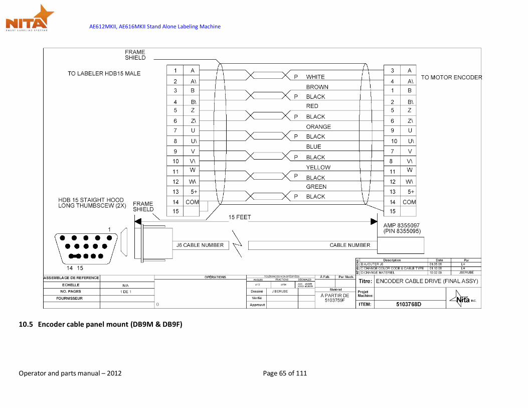
AE612MKII, AE616MKII Stand Alone Labeling Machine
Operator and parts manual – 2012 Page 65 of 111
10.5 Encoder cable panel mount (DB9M & DB9F)

AE612MKII, AE616MKII Stand Alone Labeling Machine
Operator and parts manual – 2012 Page 66 of 111
AE612MKII, AE616MKII Stand Alone Labeling Machine
Operator and parts manual – 2012 Page 67 of 111
11 WARRANTY
The standard warranty period for this Nita equipment is 12 months following invoicing. The warranty covers all parts with consideration taken towards reasonable use and normal wear and tear. Not covered by warranty are parts that have a limited wear factor, any required labor by Nita and any shipping to or from Nita of defective or new parts. Prior to return to Nita, parts must be verified defective. The regular hours covered by the Nita warranty fall under the Nita business hours which are from 8:00 a.m. to 5:00 p.m. Monday through Friday Eastern time.
Return of defective parts
To return a defective part, you need to get a RMA number from Nita. Specify the serial number of the equipment, the client’s name, address and phone number, contact name and the nature of the problem.
To get a replacement part, you must produce a purchase order as you would with any regular part order. You will be billed for the new part and credited for the defective one after evaluation. If the part is determined to be defective due to improper use, no credit will be issued. Note: shipping charges for the new part and for the return of the defective one are at your expense.
Proprietorship and Risk of Loss
NITA reserves ownership of all equipment ordered by (END USER) until complete payment is received. NITA has the right to claim and repossess any equipment which has not been paid on date, wherever it is, whether it has been installed or not, and to use any means necessary or useful to exercise said right, at (END USER’S) expenses.
Notwithstanding NITA’s reservation of ownership, (END USER) becomes fully responsible for loss of or damages to NITA’s equipment, as of the date where NITA made the equipment available for pick-up by (END USER). Appropriate Use of Equipment
The equipment supplied to the end user by Nita are to be used for the sole purpose for which they were intended and must follow Nita’s specifications on usage as well as appropriate functions. Nita will not assume any responsibility for any inappropriate use or modifications to the said equipment other than for the use it was initially built for.
The warranty will cease to apply forthwith if, in NITA’s opinion, the equipment has been used abnormally or in an abusive manner, of it has not been properly maintained, if it has not been carried on a truck equipped with an air-ride suspension when required by NITA or if it has been used or maintained contrary to the owner’s manual provided by NITA.
Responsibility Limits
The solution put forth has been prepared with the information that has been provided to Nita by the end user. Subsequently, Nita cannot assume any responsibility for the exactitude, precision and validity of the information which was supplied. Moreover, Nita cannot be held responsible for (a) any damages, direct or indirect, secondary, or accessory , including, without limitations, the loss of profit, workflow interruption, loss of production, loss of profits and other; (b) any and all damages claimed against the end user by a third party ; (c)

AE612MKII, AE616MKII Stand Alone Labeling Machine
Operator and parts manual – 2012 Page 68 of 111
all or any damages caused to the property of end user or any other third party; (d) any or all damages resulting in an act from end user or third party, major force, or act of God, unforeseen cause, or event.
With all reservation, in the eventuality where the responsibility is that of Nita relative to any defect of quality of said equipment or proposed solution Nita would be able to Accept the responsibility, to its entire discretion, with the replacement of part of or the said equipment or solution. By a compatible or identical equipment or solution or by a reimbursement of value agreed upon. In no case can Nita’s responsibility exceed the total monetary sums received for the said defective equipment or solution.

AE612MKII, AE616MKII Stand Alone Labeling Machine
Operator and parts manual – 2012 Page 69 of 111
12 PARTS - COMPONENTS SCHEMATICS SECTION
12.1 PARTS LIST
Part # Description Qty
5101906 BASE KIT AE612-MKII (includes all below parts) 1
5110986 Tension roller axel – Tension roller assy 1
5110989 Round alum. Tube OD 1/14, ID 1/18 – Tension roller assy 1
5111139 Rewind transmission belt 1
5111167 Braking strap for unwind 1
8110119 Roll end plast. Bearing ID 0.5 Delrin 2
8130199 Timing belt 3/8 type XL 1
8180064 Tension spring (For Rewind) 1
8180030 Tension spring brake (old 8180019 or b-611) (For Unwind) 1
8708016 Hook for brake (old 5102031 or 04-099) 6-32 1
8708019 Hook for brake 8-32
5101907 BASE KIT AE612-MKII Wide (includes all below parts) 1
5111389 Wide Tension roller axel – Tension roller assy 1
5111387 Wide Round alum. Tube OD 1/14, ID 1/18 – Tension roller assy 1
5111139 Rewind transmission belt 1
5111167 Braking strap for unwind 1
8110119 Roll end plast. Bearing ID 0.5 Delrin 2
8130199 Timing belt 3/8 type XL 1
8180064 Tension spring (For Rewind) 1
8180030 Tension spring brake (old 8180019 or b-611) (For Unwind) 1
8708016 Hook for brake (old 5102031 or 04-099) 6-32 1
8708019 Hook for brake 8-32

AE612MKII, AE616MKII Stand Alone Labeling Machine
Operator and parts manual – 2012 Page 70 of 111

AE612MKII, AE616MKII Stand Alone Labeling Machine
Operator and parts manual – 2012 Page 71 of 111
5101908 BASE KIT AE612-MKII Extra-Wide (includes all below parts) 1
5112404 Extra-Wide Tension roller axel – Tension roller assy 1
5112406 Extra-Wide Round alum. Tube OD 1/14, ID 1/18 – Tension roller assy 1
5112419 Rewind transmission belt 5mm 1
5111167 Braking strap for unwind 1
8110119 Roll end plast. Bearing ID 0.5 Delrin 2
8130227 Timing belt 1/2 type L (150L050) 1
8180064 Tension spring (For Rewind) 1
8180030 Tension spring brake (old 8180019 or b-611) (For Unwind) 1
8708016 Hook for brake (old 5102031 or 04-099) 6-32 1
8708019 Hook for brake 8-32
5101910 BASE KIT AE616-MKII (includes all below parts) 1
5110986 Tension roller axel – Tension roller assy 1
5110989 Round alum. Tube OD 1/14, ID 1/18 – Tension roller assy 1
8125003 Polyclutch slipper shaft 1
5111167 Braking strap for unwind 1
8110119 Roll end plast. Bearing ID 0.5 Delrin 2
8130199 Timing belt 3/8 type XL 1
8180065 Tension spring (Rewind) 1
8180030 Tension spring brake (old 8180019 or b-611) (For Unwind) 1
8708016 Hook for brake (old 5102031 or 04-099) 6-32 1
8708019 Hook for brake 8-32 1
5101911 BASE KIT AE616-MKII Wide (includes all below parts) 1
5111389 Wide Tension roller axel – Tension roller assy 1
5111387 Wide Round alum. Tube OD 1/14, ID 1/18 – Tension roller assy 1
8125003 Polyclutch slipper shaft 1
5111167 Braking strap for unwind 1

AE612MKII, AE616MKII Stand Alone Labeling Machine
Operator and parts manual – 2012 Page 72 of 111
8110119 Roll end plast. Bearing ID 0.5 Delrin 2
8130199 Timing belt 3/8 type XL 1
8180065 Tension spring (For Rewind) 1
8180030 Tension spring brake (old 8180019 or b-611) (For Unwind) 1
8708016 Hook for brake (old 5102031 or 04-099) 6-32 1
8708019 Hook for brake 8-32
Electrical section
5101777 GAP SENSOR, LABEL EYE 1
8325093 GAP SENSOR, CLEAR LABEL (TRITRONIC) 1
8325086 GAP SENSOR, CLEAR LABEL (DI-SORIC) 1
8325058 PRODUCT REFLECTIVE SENSOR FOR CLEAR PRODUCT (STANDARD ON ALL SYNER G XP AND JOUST SYSTEM)
1
8325066 PRODUCT PROXIMITY REFLEX SENSOR 1
8325087 LOW WEB PROXIMITY PHOTOELECTRIC PNP 1
8301036 HMI 3.5” MONO 1
8301079 POWER SUPPLY 24 VDC, 60 W IDEC 1
8301091 INTERFACE BOARD EPSILON EP 16 IN – 8 OUT 1
8311032 EPSILON DRIVE EP INDEXING C/W ETHERNET CABLE 1
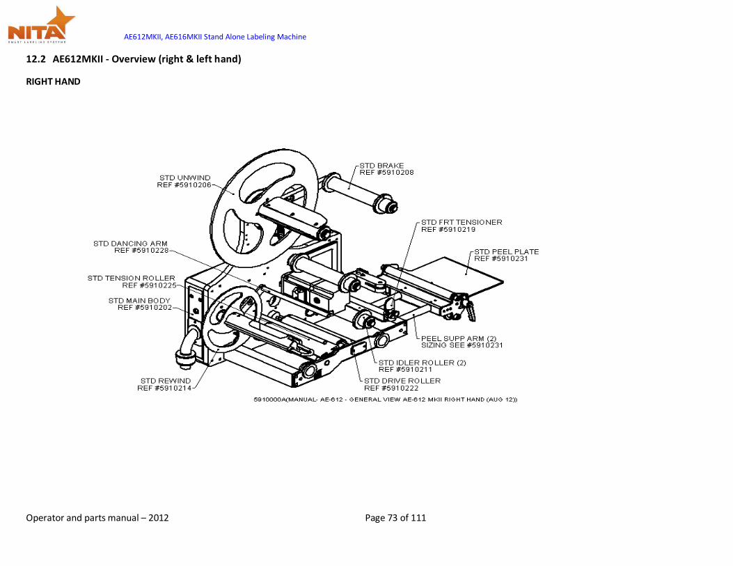
AE612MKII, AE616MKII Stand Alone Labeling Machine
Operator and parts manual – 2012 Page 73 of 111
12.2 AE612MKII - Overview (right & left hand)
RIGHT HAND
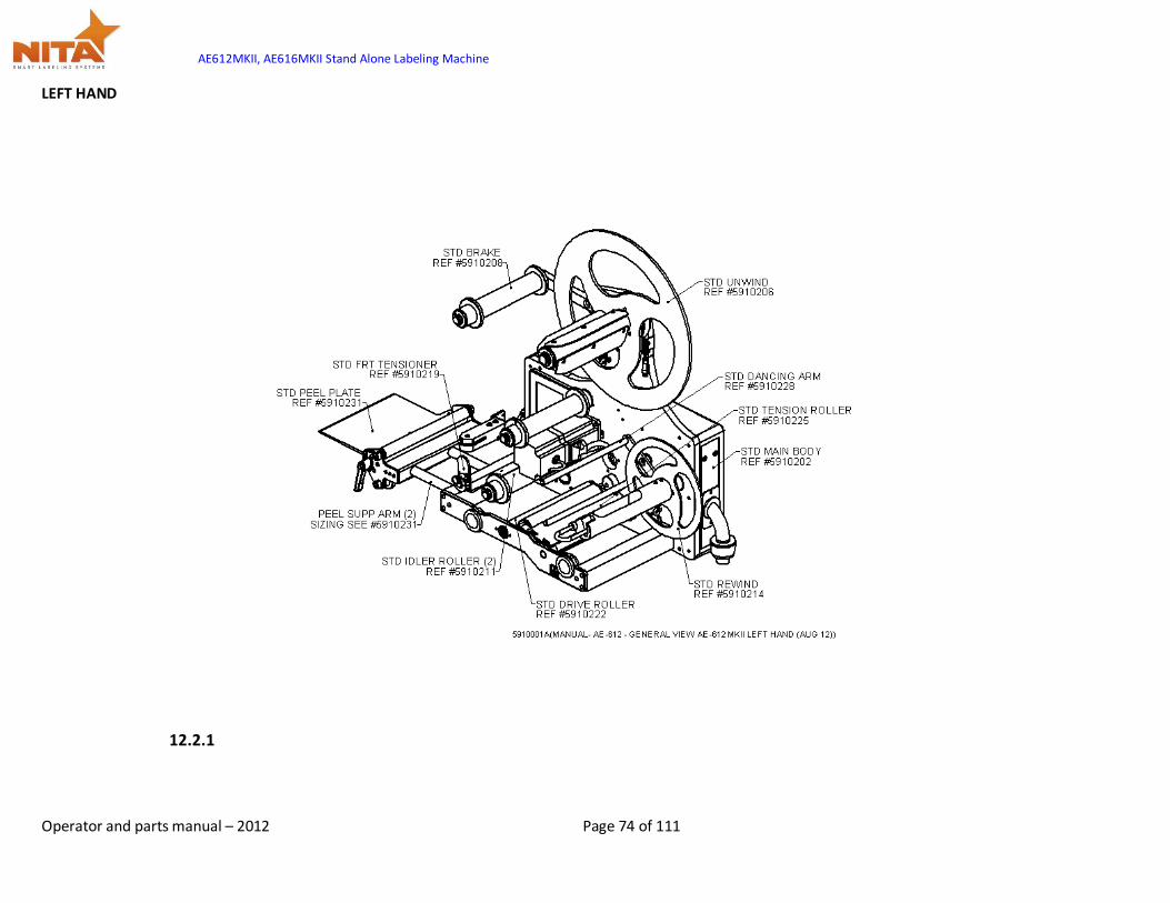
AE612MKII, AE616MKII Stand Alone Labeling Machine
Operator and parts manual – 2012 Page 74 of 111
LEFT HAND
12.2.1
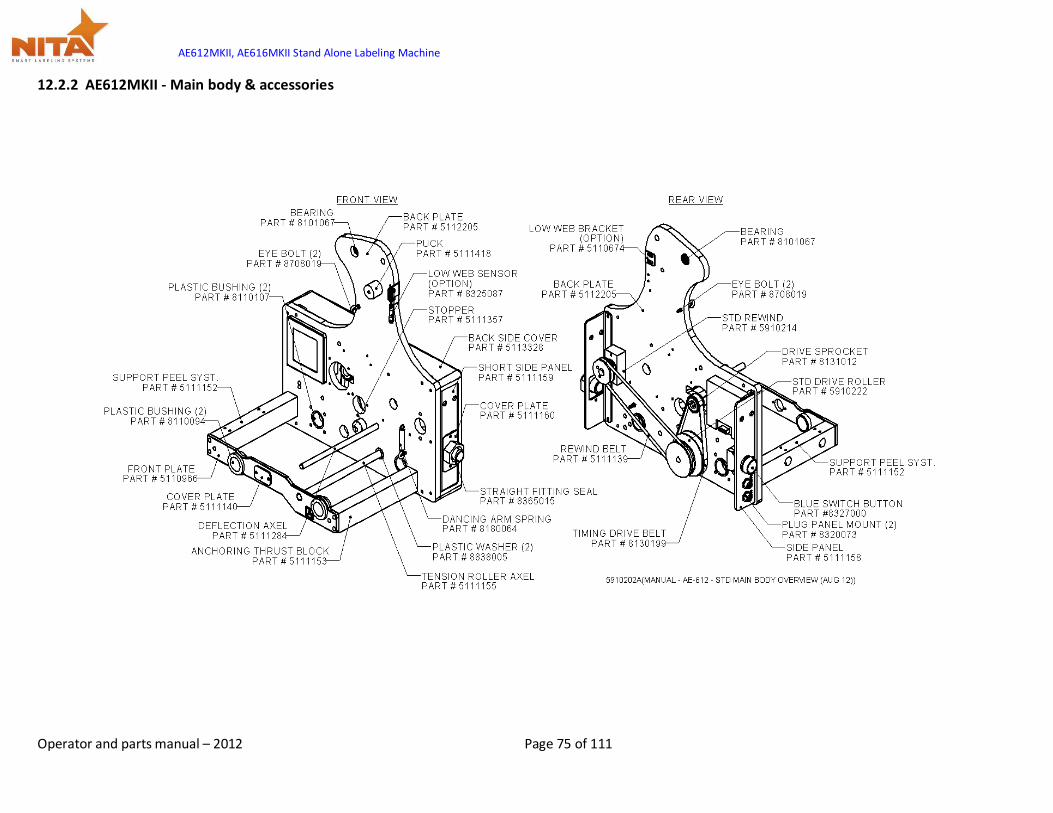
AE612MKII, AE616MKII Stand Alone Labeling Machine
Operator and parts manual – 2012 Page 75 of 111
12.2.2 AE612MKII - Main body & accessories

AE612MKII, AE616MKII Stand Alone Labeling Machine
Operator and parts manual – 2012 Page 76 of 111
12.2.3 AE612MKII - Peel plate assy
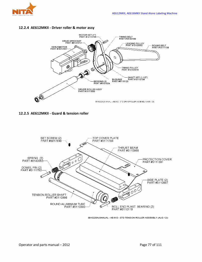
AE612MKII, AE616MKII Stand Alone Labeling Machine
Operator and parts manual – 2012 Page 77 of 111
12.2.4 AE612MKII - Driver roller & motor assy
12.2.5 AE612MKII - Guard & tension roller
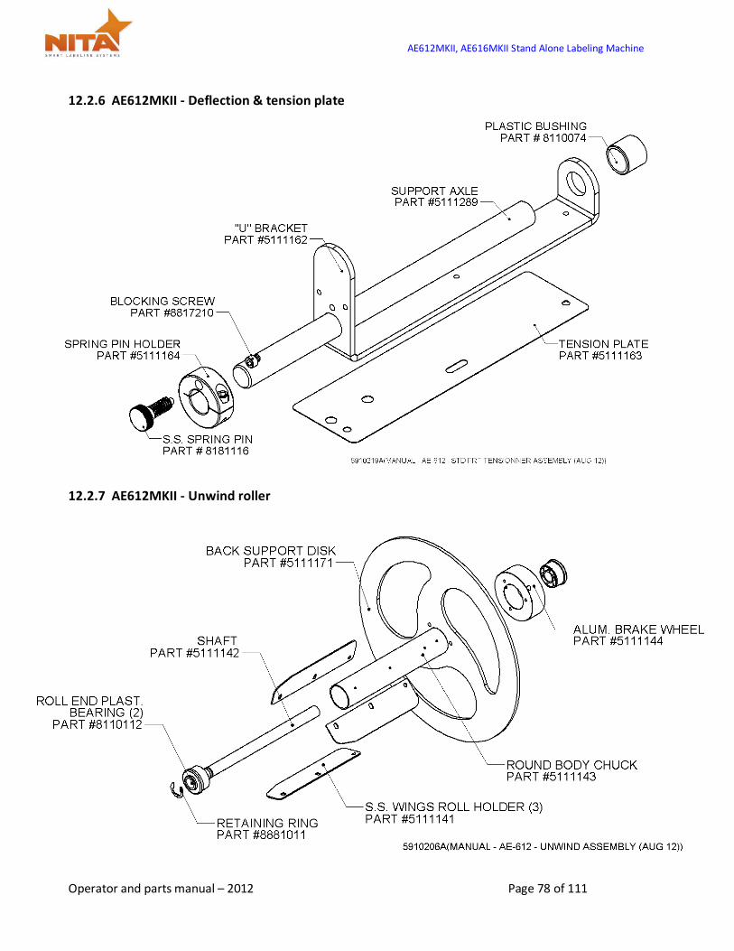
AE612MKII, AE616MKII Stand Alone Labeling Machine
Operator and parts manual – 2012 Page 78 of 111
12.2.6 AE612MKII - Deflection & tension plate
12.2.7 AE612MKII - Unwind roller
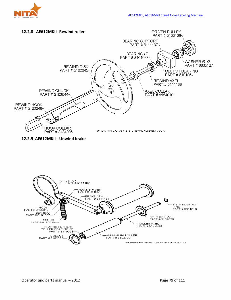
AE612MKII, AE616MKII Stand Alone Labeling Machine
Operator and parts manual – 2012 Page 79 of 111
12.2.8 AE612MKII- Rewind roller
12.2.9 AE612MKII - Unwind brake
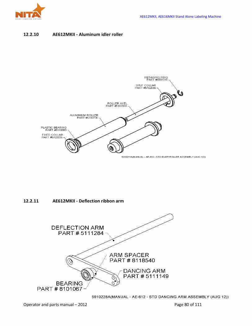
AE612MKII, AE616MKII Stand Alone Labeling Machine
Operator and parts manual – 2012 Page 80 of 111
12.2.10 AE612MKII - Aluminum idler roller
12.2.11 AE612MKII - Deflection ribbon arm

AE612MKII, AE616MKII Stand Alone Labeling Machine
Operator and parts manual – 2012 Page 81 of 111
12.3 AE612MKII WIDE - Overview wide labeler head (right & left hand)
RIGHT HAND
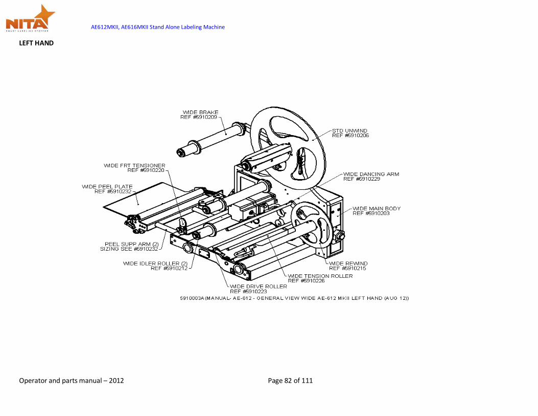
AE612MKII, AE616MKII Stand Alone Labeling Machine
Operator and parts manual – 2012 Page 82 of 111
LEFT HAND
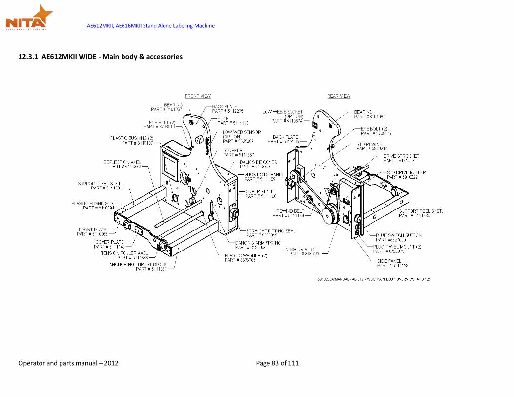
AE612MKII, AE616MKII Stand Alone Labeling Machine
Operator and parts manual – 2012 Page 83 of 111
12.3.1 AE612MKII WIDE - Main body & accessories
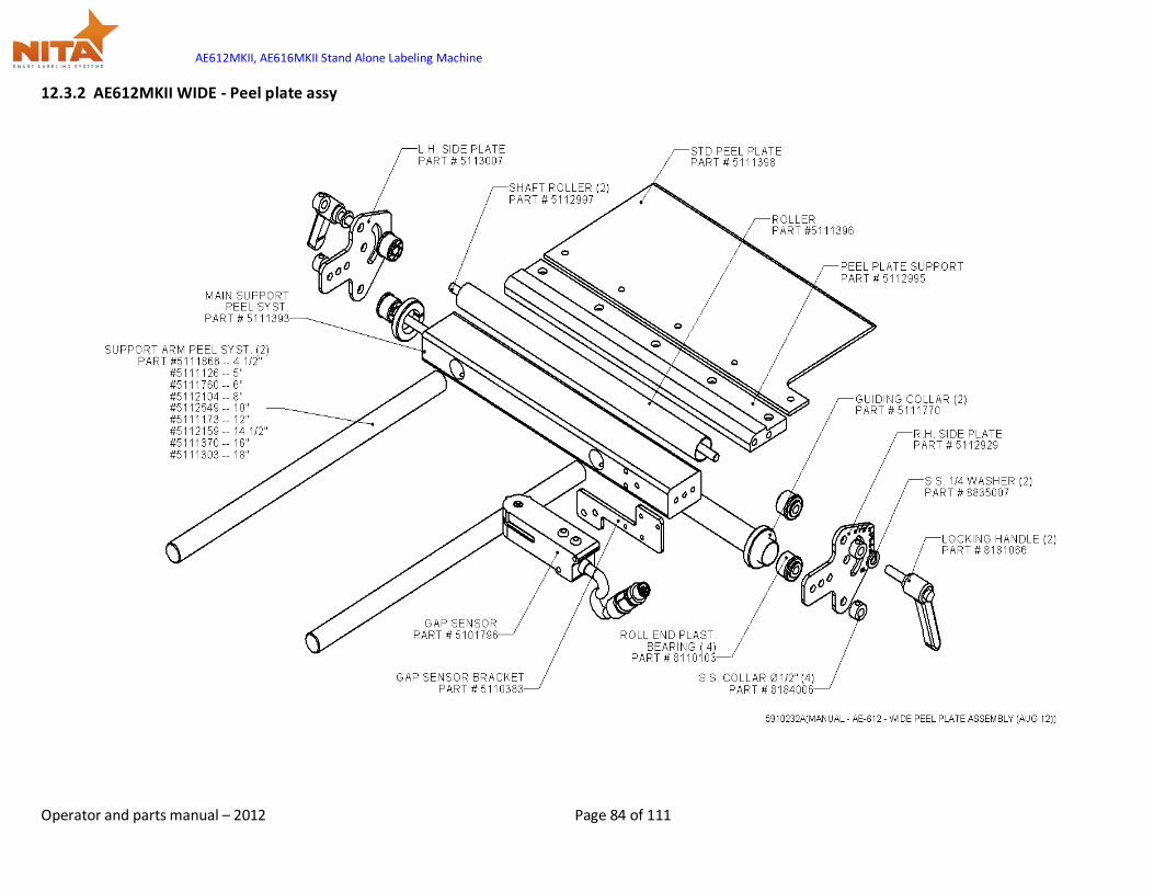
AE612MKII, AE616MKII Stand Alone Labeling Machine
Operator and parts manual – 2012 Page 84 of 111
12.3.2 AE612MKII WIDE - Peel plate assy
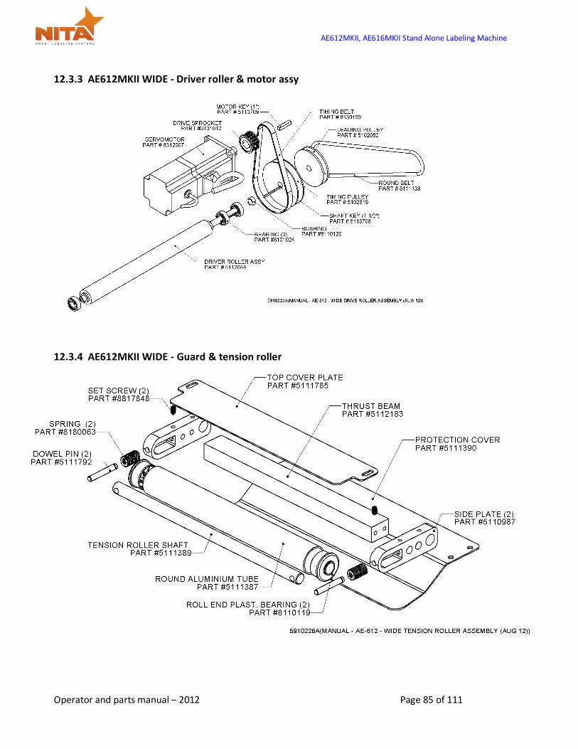
AE612MKII, AE616MKII Stand Alone Labeling Machine
Operator and parts manual – 2012 Page 85 of 111
12.3.3 AE612MKII WIDE - Driver roller & motor assy
12.3.4 AE612MKII WIDE - Guard & tension roller
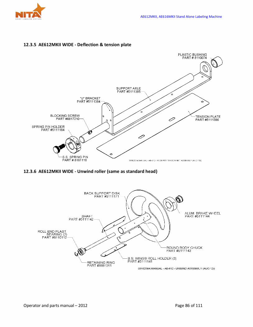
AE612MKII, AE616MKII Stand Alone Labeling Machine
Operator and parts manual – 2012 Page 86 of 111
12.3.5 AE612MKII WIDE - Deflection & tension plate
12.3.6 AE612MKII WIDE - Unwind roller (same as standard head)
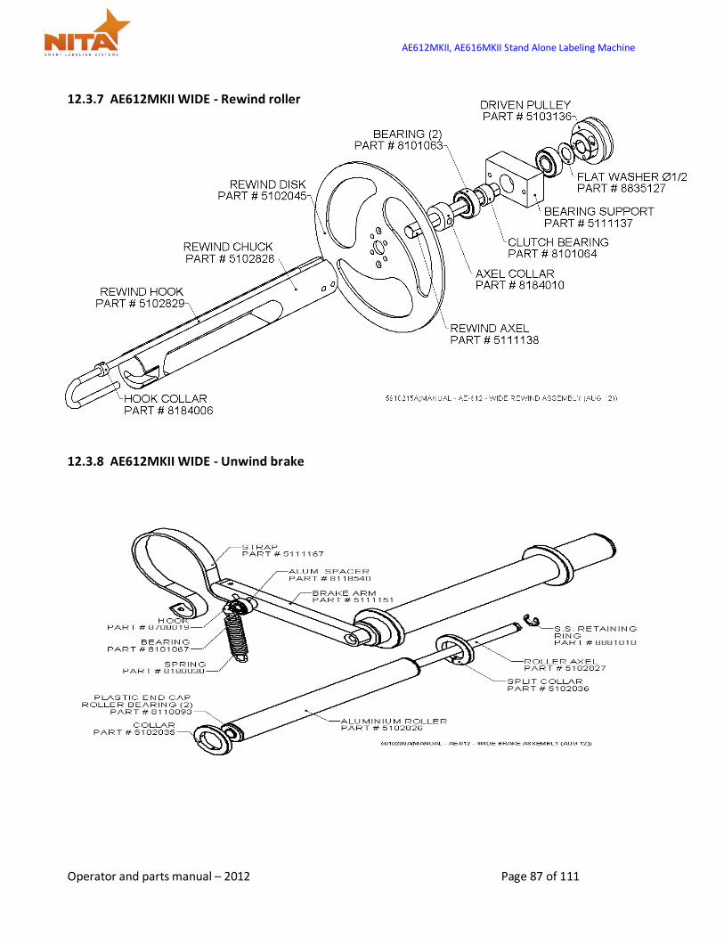
AE612MKII, AE616MKII Stand Alone Labeling Machine
Operator and parts manual – 2012 Page 87 of 111
12.3.7 AE612MKII WIDE - Rewind roller
12.3.8 AE612MKII WIDE - Unwind brake
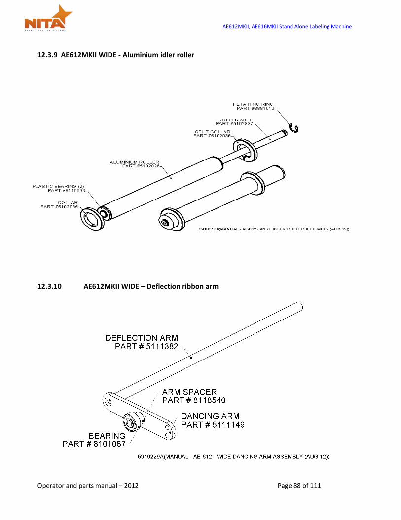
AE612MKII, AE616MKII Stand Alone Labeling Machine
Operator and parts manual – 2012 Page 88 of 111
12.3.9 AE612MKII WIDE - Aluminium idler roller
12.3.10 AE612MKII WIDE – Deflection ribbon arm
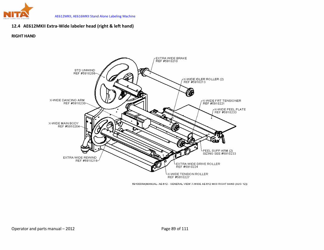
AE612MKII, AE616MKII Stand Alone Labeling Machine
Operator and parts manual – 2012 Page 89 of 111
12.4 AE612MKII Extra-Wide labeler head (right & left hand)
RIGHT HAND

AE612MKII, AE616MKII Stand Alone Labeling Machine
Operator and parts manual – 2012 Page 90 of 111
LEFT HAND
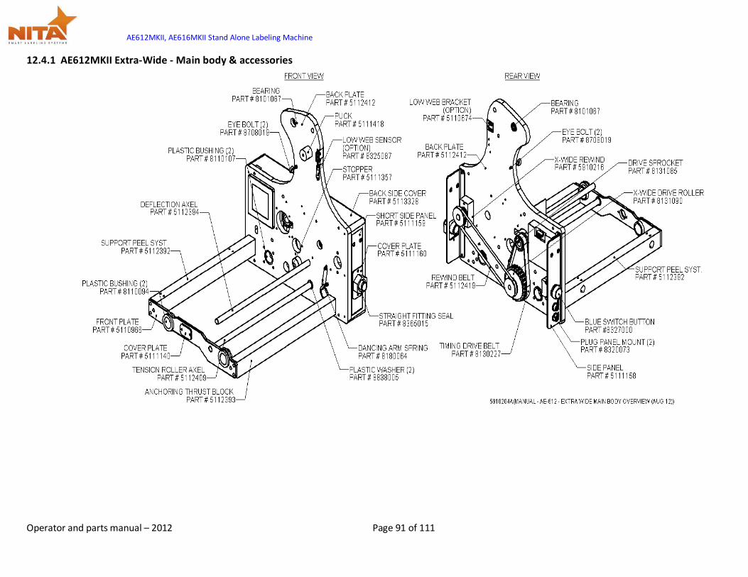
AE612MKII, AE616MKII Stand Alone Labeling Machine
Operator and parts manual – 2012 Page 91 of 111
12.4.1 AE612MKII Extra-Wide - Main body & accessories
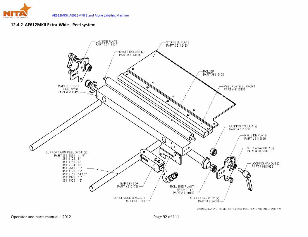
AE612MKII, AE616MKII Stand Alone Labeling Machine
Operator and parts manual – 2012 Page 92 of 111
12.4.2 AE612MKII Extra-Wide - Peel system

AE612MKII, AE616MKII Stand Alone Labeling Machine
Operator and parts manual – 2012 Page 93 of 111
12.4.3 AE612MKII Extra-Wide - Driver roller & motor assy
12.4.4 AE612MKII Extra-Wide - Guard & tension roller

AE612MKII, AE616MKII Stand Alone Labeling Machine
Operator and parts manual – 2012 Page 94 of 111
12.4.5 AE612MKII Extra-Wide - Deflection & tension plate
12.4.6 AE612MKII Extra-Wide - Unwind roller (same as standard head)
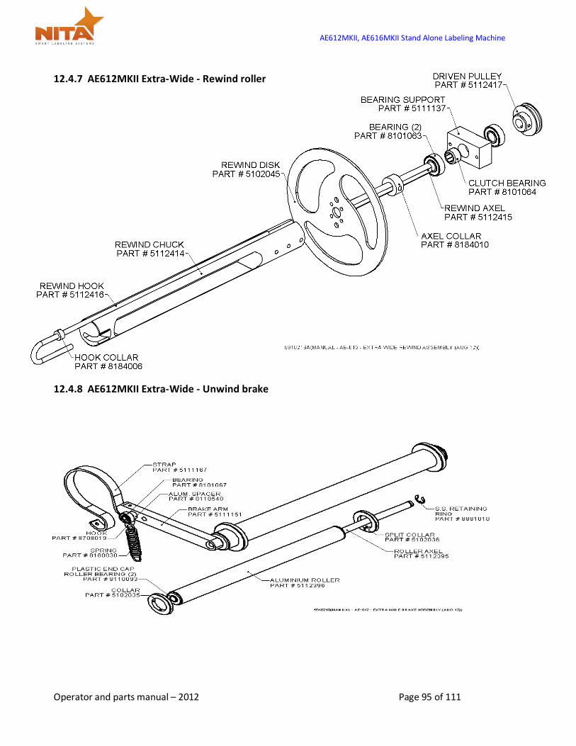
AE612MKII, AE616MKII Stand Alone Labeling Machine
Operator and parts manual – 2012 Page 95 of 111
12.4.7 AE612MKII Extra-Wide - Rewind roller
12.4.8 AE612MKII Extra-Wide - Unwind brake
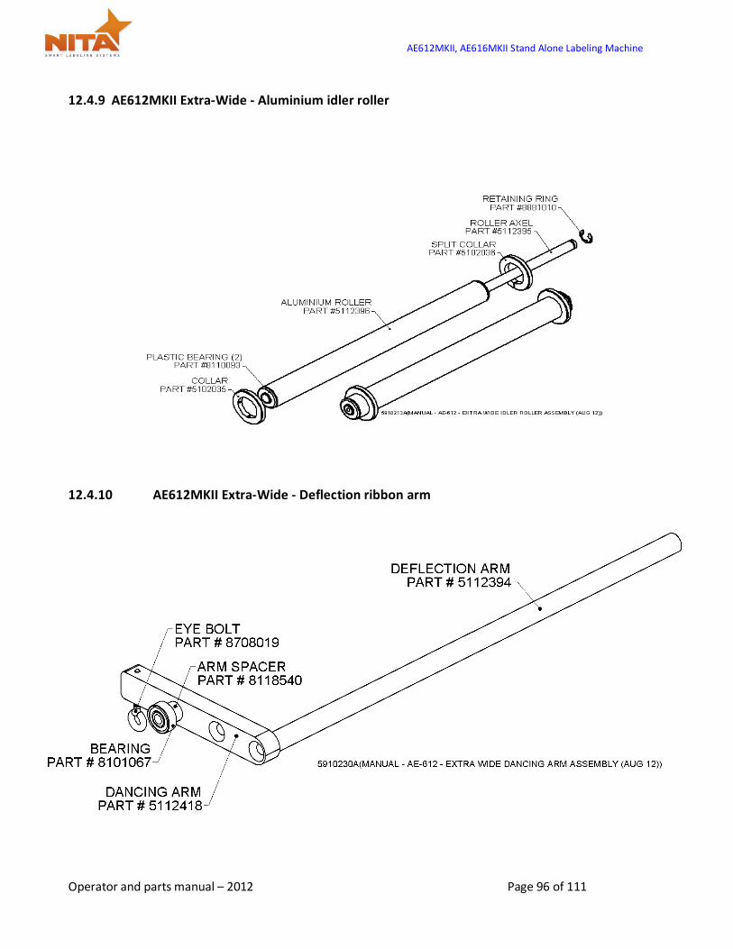
AE612MKII, AE616MKII Stand Alone Labeling Machine
Operator and parts manual – 2012 Page 96 of 111
12.4.9 AE612MKII Extra-Wide - Aluminium idler roller
12.4.10 AE612MKII Extra-Wide - Deflection ribbon arm
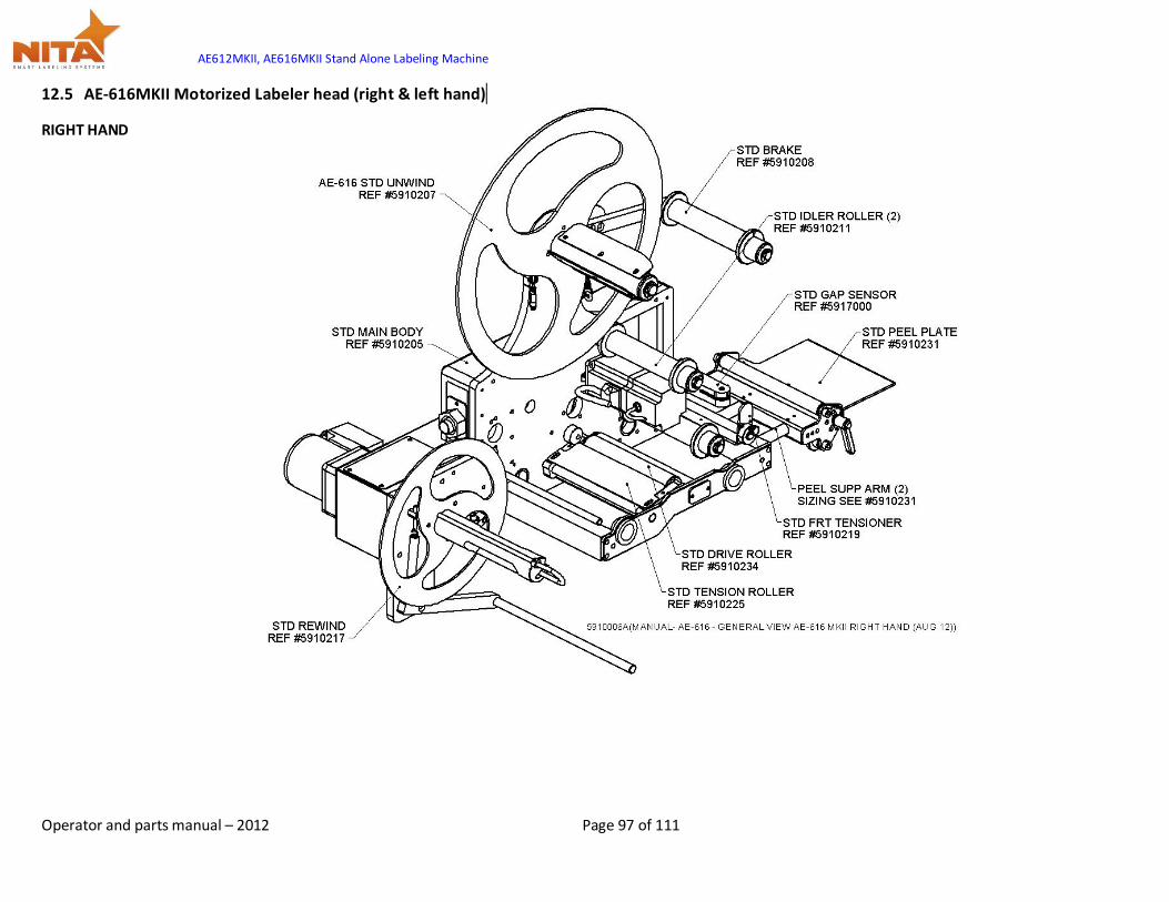
AE612MKII, AE616MKII Stand Alone Labeling Machine
Operator and parts manual – 2012 Page 97 of 111
12.5 AE-616MKII Motorized Labeler head (right & left hand)
RIGHT HAND
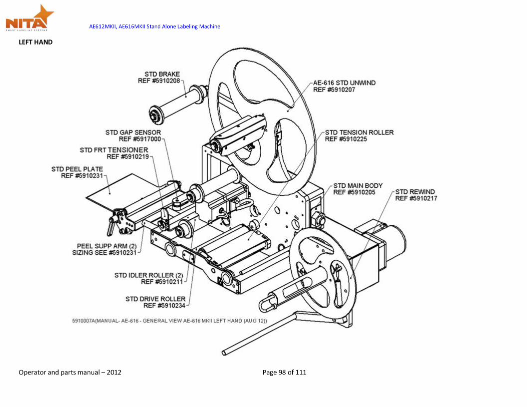
AE612MKII, AE616MKII Stand Alone Labeling Machine
Operator and parts manual – 2012 Page 98 of 111
LEFT HAND
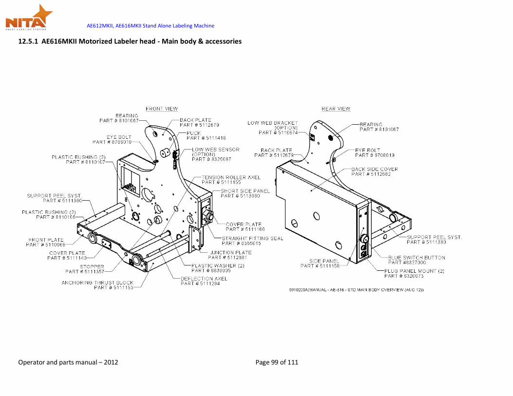
AE612MKII, AE616MKII Stand Alone Labeling Machine
Operator and parts manual – 2012 Page 99 of 111
12.5.1 AE616MKII Motorized Labeler head - Main body & accessories
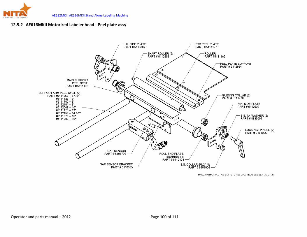
AE612MKII, AE616MKII Stand Alone Labeling Machine
Operator and parts manual – 2012 Page 100 of 111
12.5.2 AE616MKII Motorized Labeler head - Peel plate assy
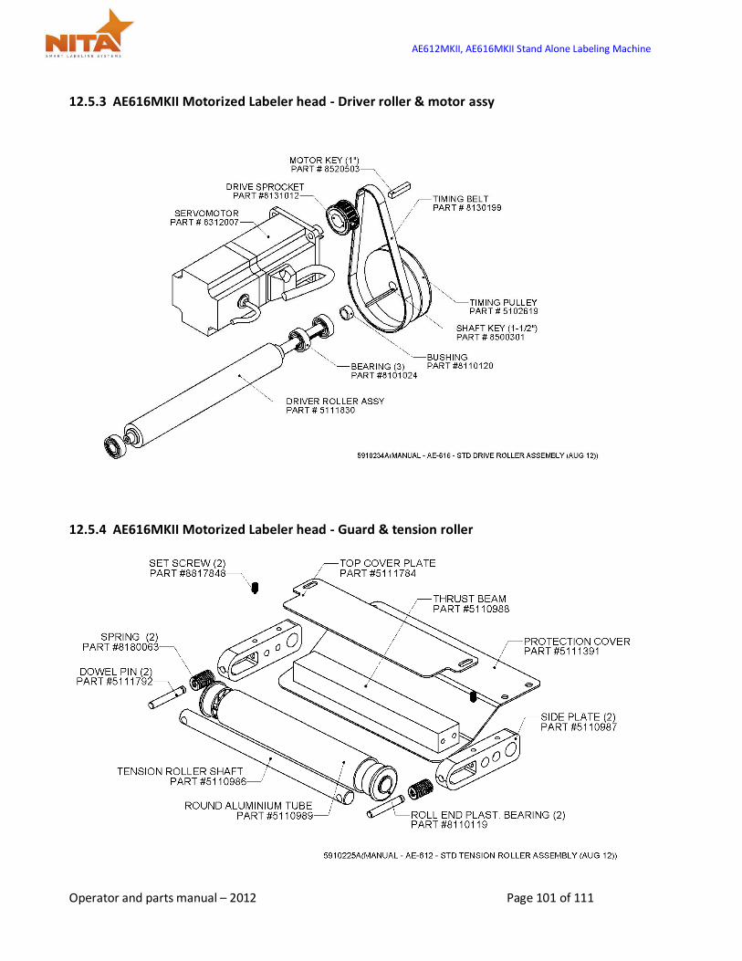
AE612MKII, AE616MKII Stand Alone Labeling Machine
Operator and parts manual – 2012 Page 101 of 111
12.5.3 AE616MKII Motorized Labeler head - Driver roller & motor assy
12.5.4 AE616MKII Motorized Labeler head - Guard & tension roller

AE612MKII, AE616MKII Stand Alone Labeling Machine
Operator and parts manual – 2012 Page 102 of 111
12.5.5 AE616MKII Motorized Labeler head - Deflection & tension plate
12.5.6 AE616MKII Motorized Labeler head - Ø16” Unwind roller

AE612MKII, AE616MKII Stand Alone Labeling Machine
Operator and parts manual – 2012 Page 103 of 111
12.5.7 AE-616MKII Motorized Labeler head - Rewind roller
12.5.8 AE616MKII Motorized Labeler head - Motorized rewind assy
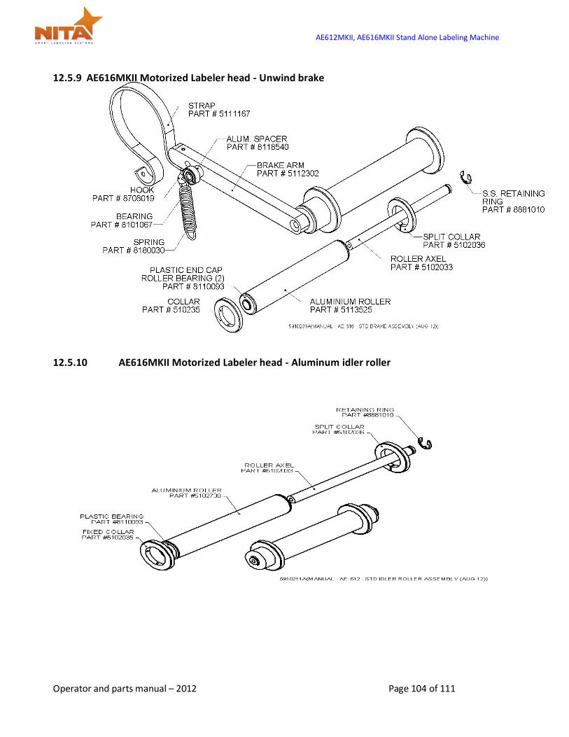
AE612MKII, AE616MKII Stand Alone Labeling Machine
Operator and parts manual – 2012 Page 104 of 111
12.5.9 AE616MKII Motorized Labeler head - Unwind brake
12.5.10 AE616MKII Motorized Labeler head - Aluminum idler roller
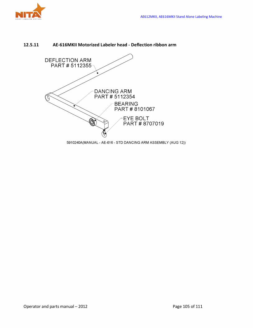
AE612MKII, AE616MKII Stand Alone Labeling Machine
Operator and parts manual – 2012 Page 105 of 111
12.5.11 AE-616MKII Motorized Labeler head - Deflection ribbon arm

AE612MKII, AE616MKII Stand Alone Labeling Machine
Operator and parts manual – 2012 Page 106 of 111
12.6 Lateral Adjustment
12.7 U-Arm

AE612MKII, AE616MKII Stand Alone Labeling Machine
Operator and parts manual – 2012 Page 107 of 111
12.8 Brush Kit

AE612MKII, AE616MKII Stand Alone Labeling Machine
Operator and parts manual – 2012 Page 108 of 111
12.9 Wide Brush Kit
12.10 Stainless Steel T Base Floor Stand

AE612MKII, AE616MKII Stand Alone Labeling Machine
Operator and parts manual – 2012 Page 109 of 111
12.11 Painted Steel T Base Floor Stand
12.12 Sliding Cart
AE612MKII, AE616MKII Stand Alone Labeling Machine
Operator and parts manual – 2012 Page 110 of 111
13 MANUFACTURER’S COORDINATES
Ultimately, the dealer which sold you the machine should be your first contact as they have been trained to perform any work on these devices and troubleshooting.
Should you require any additional information about our equipment, feel free to call us
NITA LABELING EQUIPMENT INC.
1051 du VIGER STREET
TERREBONNE, QUEBEC, CANADA
J6W 6B6
TEL : 450-961-4000 or 1-877-961-4008
FAX : 450-961-4240
WEB : www. nitaLabelingequipment.com


