1
OPERATOR MANUAL
DIRECT DRIVE ROOT/CEREAL
BUCKET
MICRO, MINI, 6’6 & 7’6 MODELS
www.agriweld.co.uk
The Workshops
Main Street
Garton-on-the-Wolds
Driffield, YO25 3ET
Tel: 01377 259140
Fax: 01377 259141
Email: [email protected]
2
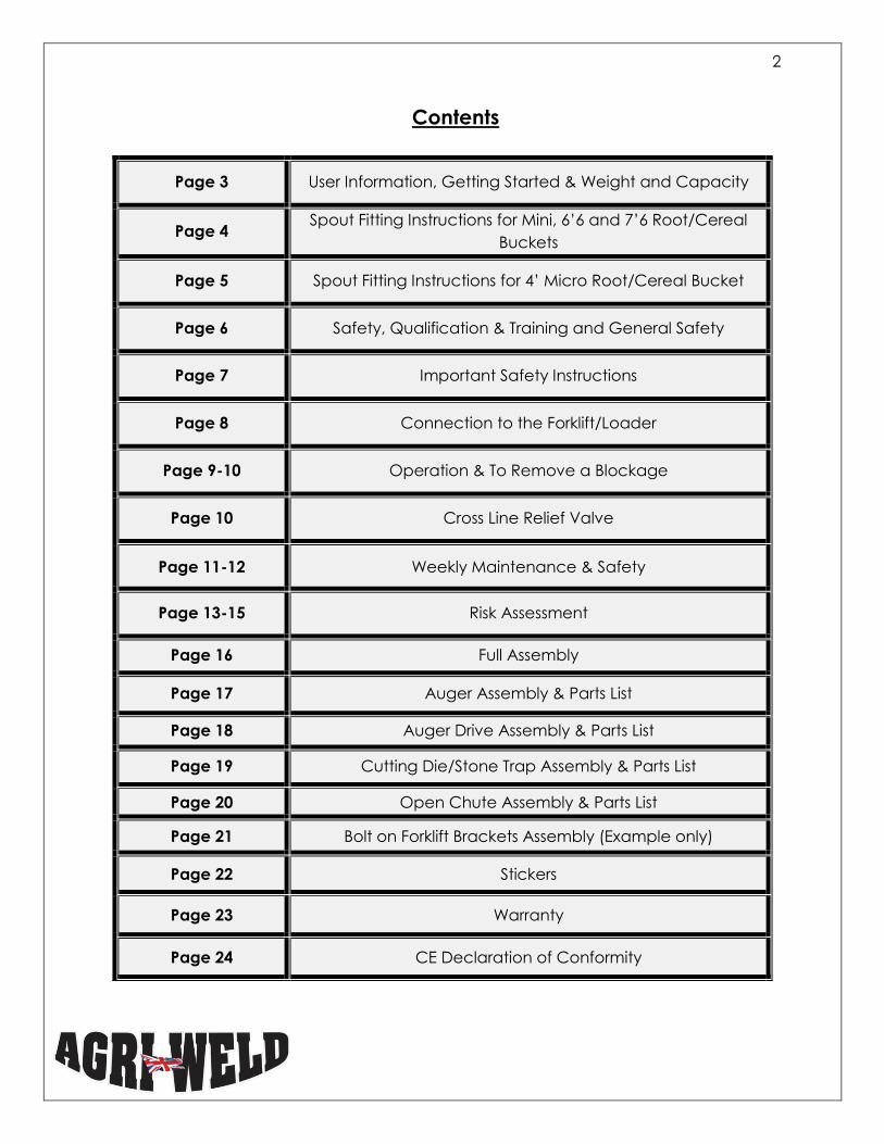
Contents
Page 3 User Information, Getting Started & Weight and Capacity
Page 4 Spout Fitting Instructions for Mini, 6’6 and 7’6 Root/Cereal
Buckets
Page 5 Spout Fitting Instructions for 4’ Micro Root/Cereal Bucket
Page 6 Safety, Qualification & Training and General Safety
Page 7 Important Safety Instructions
Page 8 Connection to the Forklift/Loader
Page 9-10 Operation & To Remove a Blockage
Page 10 Cross Line Relief Valve
Page 11-12 Weekly Maintenance & Safety
Page 13-15 Risk Assessment
Page 16 Full Assembly
Page 17 Auger Assembly & Parts List
Page 18 Auger Drive Assembly & Parts List
Page 19 Cutting Die/Stone Trap Assembly & Parts List
Page 20 Open Chute Assembly & Parts List
Page 21 Bolt on Forklift Brackets Assembly (Example only)
Page 22 Stickers
Page 23 Warranty
Page 24 CE Declaration of Conformity
3
USER INFORMATION
Before using your DIRECT DRIVE Root/Cereal Bucket for the first time it is important that
all operators make themselves familiar with the unit and must read this Operator
Manual attentively.
GETTING STARTED
Your DIRECT DRIVE Root/Cereal Bucket will be fitted and delivered with the correct
brackets to suit the Skid Steer/Telehandler/front loader it is intended to fit. If for any
reason the fittings are lost or damaged, or if the bracketing is removed for any reason,
please refer back to this information in order to refit the brackets and/or replace any
lost fittings with the correct specification.
Your DIRECT DRIVE Root/Cereal Bucket will also be fitted with the correctly swaged
hydraulic pipes and fittings applicable to your forklift/loader and as per your request. If
these pipes are damaged they must be replaced immediately with new pipes and
fittings. DO NOT ATTEMPT TO REPAIR HYDRAULIC PIPES OR ALLOW ANY ONE ELSE TO
REPAIR THEM.
Any replacements can be ordered from us and sent to you overnight if required.
Your DIRECT DRIVE Root/Cereal Bucket is a low maintenance machine, and requires
minimum mechanical attention as such, other than greasing.
MODEL WEIGHTS & CAPACITIES (approx.)
MICRO (4’) MODEL Maximum 0.3m³ 320kgs (including weld on brackets)
MINI (5’) MODEL Maximum 0.75m³ 405kg (excluding bolt on brackets)
6’6 MODEL Maximum 1.5m³ 535kgs (excluding bolt on brackets)
7’6 MODEL Maximum 1.7m³ 610kgs (excluding bolt on brackets)
Your DIRECT DRIVE Root/Cereal Bucket is not to be used for any other purpose than for
which it is intended - that is the collection, discharge and chopping of root feed and
discharging cereals. Damage as a result of use for other purposes will not be covered
under warranty.
4
The specifications, descriptions and illustrations in this manual are accurate at the time
of publication but may be subject to change.
SPOUT FITTING INSTRUCTIONS for Mini, 6’6 and 7’6 models
1. The Stone trap assembly requires bolting into position on bucket first via flange.
2. Push spout shaft fully in to nylon bush located on end of auger shaft (see
drawing)
3. Spout will turn freely on shaft to enable the bolt holes on the spout to line up with
the bolt holes on the stone trap assembly.
4. Locate fixing bolts (M10 x 30mm) x 6 into flanges, and ensure flange edges are
flush and level and tighten bolts using washers (on nylock side only) and nylock
nuts. Ensure these are tight.
Nylon Bush – fitted
within auger shaft &
shown for illustration
only
Stone trap
Spout Auger shaft
5
Micro Root/Cereal Spout Fitting Instructions
Item Number Part Number Description Quantity per Machine
1 SSMB_Ass_02 Spout Assembly 1
2 SSMB_0409 Spout door 1
3 SSMB_Spout_Lever Spout door release 1
4 CR_Ny_Bush Nylon Bush 1
5 AW_M10_NL M10 Nyloc nut 13
6 AW_M10_W M10 Washer 26
7 AW_M10x35_B M10 x 35mm Bolt 13
1
2
3
5
4
6 7
6
SAFETY
All operators of the buckets forklift/loader must hold the appropriate forklift licence or
certificate of competence to do so.
All operators must be familiar with the DIRECT DRIVE Root/Cereal Bucket Operators
Manual and forklift/loader operations prior to use. If safety instructions are not observed
and complied with it can lead to the risk of injury to the operator and others as well as
damage to the machine, property and the environment. Non-compliance to the
safety instructions can lead to claims for damages/injury becoming invalid.
QUALIFICATION & TRAINING
Only personnel with the appropriate forklift/loader licence are authorised to use this
machine.
Statutory minimum age limits must be observed and reliable personnel only should
perform maintenance/work on this machine.
Persons undergoing training or instruction or taking part in a general training course
should only use this machine under direct supervision of an experienced and trained
person.
Agriweld shall not be responsible for any damage/injury caused by the use of
parts/repairs not supplied and/or approved by Agriweld.
GENERAL SAFETY
Any warning signs/instructions on the machine provide important information and must
be observed.
Ensure that you are familiar with the machine before starting work.
Check round the machine for any noticeable damage, or missing parts before starting
work.
It is advisable that the operator does not wear jewellery and baggy clothing to avoid
the risk of snagging and trapping.
Ensure that you are working in an area clear of obstructions and watch out for
wandering individuals (particularly children!). Ensure that you are working in an area
clear of obstructions and watch out for wandering individuals (particularly children!).
7
IMPORTANT SAFETY INSTRUCTIONS
Take extra care when attaching the DIRECT DRIVE Root/Cereal Bucket to the
forklift/loader to ensure that it is attached correctly via the bracketing and hydraulic
fittings. (See page 7 Connection to the forklift/loader).
Ensure that the forklift/loader and its hydraulic system are in full working order.
Never allow any person to stand between the forklift/loader and the DIRECT DRIVE
Root/Cereal bucket during connection or at any time.
Ensure that the brackets are attached to the loader correctly and that all
connecting ‘U’ bolts and nylock nuts are present for attaching the brackets to the
bucket, before operation.
Take into account the protrusions of the DIRECT DRIVE Root/Cereal Bucket from the
forklift carriage when manoeuvring around and take particular care when
approaching junctions and negotiating corners.
The driving characteristics of the forklift/loader are influenced and altered by the
attachment of mounted machines and it is important to ensure adequate steering
and braking ability as required.
Never allow any person to ride on or in the bucket at any time
Never perform any adjustments to the bucket whilst mounted, unless the
forklift/loader is stopped, turned off and the bucket is resting on the ground where
possible.
Ensure that the forklift/loader cannot roll away by use of a park brake or wheel
chocks.
Never allow any person to stand or work beneath a suspended load.
Increased risk of injury at discharge end, please stay clear of the cutting blade/die
and auger at all time during use and when connected to the hydraulics which
could cause the auger to start and bucket to begin cutting
Always ensure correct size bucket to suit loader’s capacity is used. If overloaded not
only could this cause spillage and pose a potential skidding risk but could overload
the forklift/loader causing damage/failure of loader. Operator needs to be aware
of max load of their own forklift headstock. Agriweld will accept no responsibility for
damage/failure or injury caused by operator overloading bucket
8
CONNECTION TO THE FORKLIFT/LOADER
Your DIRECT DRIVE Root/Cereal Bucket will be delivered already fitted with the correct
bracketing, hydraulic fittings and hydraulic hose to fit your forklift/loader.
If for any reason the fittings are lost or damaged they must be replaced with the
following specification of fitting;
BOLT ON BRACKETS (Mini, 6’6” and 7’6” BUCKETS)
The QUICK-HITCH brackets or LOADER brackets require the following ‘U’ Bolt fittings;
8 X M16 X 120mm U Bolts
16 X M16 Nylock nuts/washers
WELD ON BRACKETS (Micro bucket only) – No additional fittings are required.
For your own safety and the safety of others, always use the correct fittings to attach
bolt-on bracketing to the rear of the unit. Always place the unit on the ground and turn
off the forklift/loader before attempting any changes.
CREATING OFFSET - BOLT ON BRACKETS ONLY (Before Attachment to Forklift)
The bracketing on a DIRECT DRIVE bucket (other than the Micro Bucket) will be offset at
the point of manufacture, however if you need to change the offset for any reason the
procedure is as follows;
1. Remove all 16 nylock nuts and reposition the bracket.
It is important to maintain the correct spacing between the brackets and that
on tightening up the bolts make sure that the brackets remain square to the
bracket mounting frame.
Replace the M16 Nylock nuts each time the brackets have been repositioned
and ensure they are all thoroughly tightened.
WELD ON BRACKETS ATTACHMENT (Micro bucket)
The position is set in accordance with any customer offset requirements and welded to
the skid steer/loader.
Stand the MICRO Root/Cereal Bucket in an area free from obstruction to allow you to
drive the skid steer/loader towards the bracketing.
9
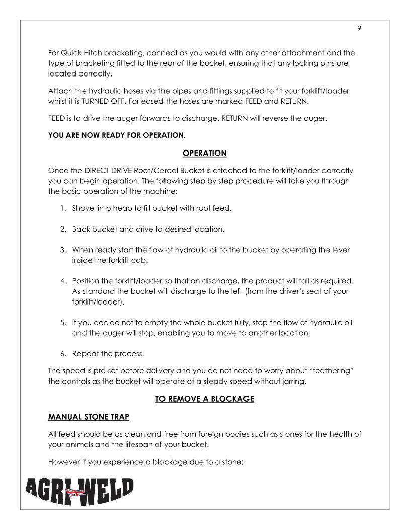
For Quick Hitch bracketing, connect as you would with any other attachment and the
type of bracketing fitted to the rear of the bucket, ensuring that any locking pins are
located correctly.
Attach the hydraulic hoses via the pipes and fittings supplied to fit your forklift/loader
whilst it is TURNED OFF. For eased the hoses are marked FEED and RETURN.
FEED is to drive the auger forwards to discharge. RETURN will reverse the auger.
YOU ARE NOW READY FOR OPERATION.
OPERATION
Once the DIRECT DRIVE Root/Cereal Bucket is attached to the forklift/loader correctly
you can begin operation. The following step by step procedure will take you through
the basic operation of the machine;
1. Shovel into heap to fill bucket with root feed.
2. Back bucket and drive to desired location.
3. When ready start the flow of hydraulic oil to the bucket by operating the lever
inside the forklift cab.
4. Position the forklift/loader so that on discharge, the product will fall as required.
As standard the bucket will discharge to the left (from the driver’s seat of your
forklift/loader).
5. If you decide not to empty the whole bucket fully, stop the flow of hydraulic oil
and the auger will stop, enabling you to move to another location.
6. Repeat the process.
The speed is pre-set before delivery and you do not need to worry about “feathering”
the controls as the bucket will operate at a steady speed without jarring.
TO REMOVE A BLOCKAGE
MANUAL STONE TRAP
All feed should be as clean and free from foreign bodies such as stones for the health of
your animals and the lifespan of your bucket.
However if you experience a blockage due to a stone;
10
1. Stop flow of oil ASAP.
2. Release pressure or back up auger ½m to free stone, which should drop into the
trap.
3. Turn off forklift/handler before leaving cab.
4. Open stone trap.
5. Release foreign object.
6. Close stone trap.
7. Re-start forklift and continue operation.
IMPORTANT
CROSS LINE RELIEF VALVE
The Cross Line Relief Valve is fitted to the top of the hydraulic motor on your feeder
bucket as additional protection for the motor and cutting die against damage from
excessively high oil pressure and the effect from stones or other foreign bodies causing
a blockage.
FIRST USE - SET THE CROSS LINE RELIEF VALVE & CHECK LOADER OIL FLOW
The Valve is pre-set to 150 bar prior to delivery in the event that you do not make any
adjustments yourself to give your motor protection against excessive oil pressure and
major blockages.
Most users do not have access to a pressure gauge to set the relief valve accurately to
avoid any pressure related damage, however, by following these guidelines relating to
setting the cross line relief valve, you will be able to successfully set the valve yourself
quite easily.
The maximum oil flow that the cross line relief valve can take is 100 litres per minute.
Please ensure that your loaders oil flow is under this limit.
NOTE: By not setting the pressure relief valve according to your feed/loader pressures &
flow, the motor is vulnerable to damage. Please see IMPORTANT NOTE ON PAGE 10.
We recommend that you re-set the Valve in accordance to your own requirements and
feed type as follows;
Before beginning, HALF fill your bucket with clean feed. That means NO stones or
foreign bodies at all while setting up.
The adjustments are made via an Allen Hex Key that is made visible on the Valve when
you remove the 2 x caps.
11
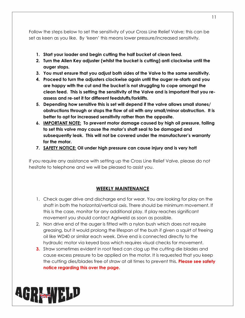
Follow the steps below to set the sensitivity of your Cross Line Relief Valve; this can be
set as keen as you like. By ‘keen’ this means lower pressure/increased sensitivity.
1. Start your loader and begin cutting the half bucket of clean feed.
2. Turn the Allen Key adjuster (whilst the bucket is cutting) anti clockwise until the
auger stops.
3. You must ensure that you adjust both sides of the Valve to the same sensitivity.
4. Proceed to turn the adjusters clockwise again until the auger re-starts and you
are happy with the cut and the bucket is not struggling to cope amongst the
clean feed. This is setting the sensitivity of the Valve and is important that you re-
assess and re-set it for different feedstuffs/forklifts.
5. Depending how sensitive this is set will depend if the valve allows small stones/
obstructions through or stops the flow of oil with any small/minor obstruction. It is
better to opt for increased sensitivity rather than the opposite.
6. IMPORTANT NOTE: To prevent motor damage caused by high oil pressure, failing
to set this valve may cause the motor’s shaft seal to be damaged and
subsequently leak. This will not be covered under the manufacturer’s warranty
for the motor.
7. SAFETY NOTICE: Oil under high pressure can cause injury and is very hot!
If you require any assistance with setting up the Cross Line Relief Valve, please do not
hesitate to telephone and we will be pleased to assist you.
WEEKLY MAINTENANCE
1. Check auger drive and discharge end for wear. You are looking for play on the
shaft in both the horizontal/vertical axis. There should be minimum movement. If
this is the case, monitor for any additional play. If play reaches significant
movement you should contact Agriweld as soon as possible.
2. Non drive end of the auger is fitted with a nylon bush which does not require
greasing, but it would prolong the lifespan of the bush if given a squirt of freeing
oil like WD40 or similar each week. Drive end is connected directly to the
hydraulic motor via keyed boss which requires visual checks for movement.
3. Straw sometimes evident in root feed can clog up the cutting die blades and
cause excess pressure to be applied on the motor. It is requested that you keep
the cutting dies/blades free of straw at all times to prevent this. Please see safety
notice regarding this over the page.
12
SAFETY
PLEASE NOTE THAT THE CUTTING BLADES ARE SHARP!
PLEASE ENSURE THE FORKLIFT/ LOADER IS SWITCHED OFF AND THE BUCKET IS RESTING ON
SOLID GROUND PRIOR TO PERFORMING ANY MAINTENANCE.
16
Full Assembly
Bolt on Brackets
Cutting Die/Stone
Trap Discharge Auger
Hydraulic Pipe
Bracket
Cross Line Relief
Valve
MOMT500 MOTOR
17
Auger Assembly
Auger Assembly Parts List
Item Number Part Number Description Quantity per Machine
1 AW_DA Discharge Auger 1
2 AW_CR_NY_Bush Nylon Auger Bush 1
3 AW_M12_30 Auger Stop Bolt 4
4 AW_M12W Auger Stop Washer 8
5 AW_M12N Auger Stop Nut 4
1
1
2
1
3
1
5
1
4
1
18
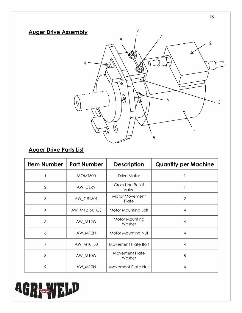
Auger Drive Assembly
Auger Drive Parts List
Item Number Part Number Description Quantity per Machine
1 MOMT500 Drive Motor 1
2 AW_CLRV Cross Line Relief
Valve 1
3 AW_CR1501 Motor Movement
Plate 2
4 AW_M12_50_CS Motor Mounting Bolt 4
5 AW_M12W Motor Mounting
Washer 4
6 AW_M12N Motor Mounting Nut 4
7 AW_M10_50 Movement Plate Bolt 4
8 AW_M10W Movement Plate
Washer 8
9 AW_M10N Movement Plate Nut 4
5
1
1
1
3
1
2
1
6
1
7
1
9
1 8
1
4
1
19
Cutting Die/Stone Trap Assembly
Stone Trap/Cutting Die Parts List
Item Number Part Number Description Quantity per Machine
1 AW_CR_Spout Cutting Die/Stone
Trap 1
2 AW_STD Stone Trap Door 1
3 AW_M10_30_CHS Cutting Die Bolt 6
4 AW_M10W Cutting Die Washer 6
5 AW_M10N Cutting Die Nut 6
1
1
2
1
5
1
4
1
3
1
20
Open Chute Assembly
Open Chute Assembly Parts List
Item Number Part Number Description Quantity per Machine
1 AW_OC Open Chute 1
2 AW_MF Manual Flap 1
3 AW_M16_110 Manual Flap Bolt 1
4 AW_M16W Manual Flap Washer 4
5 AW_M16N Manual Flap Nut 1
6 AW_MFP Manual Flap Pin 1
7 AW_LP6Z Manual Flap Linch
Pin 1
8, 9, 10
AW_M10_30CS,
AW_M10W,
AW_M10N
M10 Cup Square,
Washer & Nut 6, 6, 6
1
2
5
7 8 10
9
6 3
4
21
Bolt on Forklift Brackets Assembly (Example Only)
Forklift Brackets Parts List
Item Number Part Number Description Quantity per Machine
1 AW_M16_SB M16 Square Bend 10
2 AW_M16W M16 Washer 20
3 AW_M16N M16 Nut 10
1
1 3
1
2
1
22
Stickers
Sticker Part number Description Quantity per
Machine
AW_MRB_WS
Warning
Sticker at
discharge end
2
AW_MRB_AS
Agriweld
Sticker
1
AW_MRB_GB
Great Britain
Sticker
1
AW_MRB_RC
Root/Cereal
Sticker
2
AW_MRB_OM Operator
Manual Sticker 1
AW_MRB_OF
Do Not Over
Fill Bucket
Sticker
1
23
Warranty
Your Agriweld Direct Drive Root Cereal Bucket is covered for a period of 12
months from the date of dispatch (which is recorded on our files) against faulty
components and/or bad workmanship.
Our welders are coded to ISO 9606-1 and our welding procedures are approved
in accordance with ISO 15614-1 to manufacture your equipment. All products
are checked for quality prior to delivery/collection.
We cannot be responsible for claims arising from ignorance, occurrences
outside our control, such as accidents, and malicious damage and non-
compliance with safety instructions.
Any damage occurred during transit must be reported on signing for the item
from the haulier to enable us to enter a claim for damages direct with the
haulier.
WARRANTY CLAIMS FOR DAMAGE DURING TRANSIT
Damage occurred during transit via an external haulier must be reported
immediately upon unloading and signing for the item. The limit of our liability to
undertake repairs to products damaged during transit is dependent on signing
for any damaged product upon delivery as “DAMAGED”.
IT IS IMPORTANT TO READ THE MAINTENANCE SECTION
OF THIS MANUAL.
IT IS VERY IMPORTANT TO USE YOUR BUCKET IN
ACCORDANCE WITH ITS CAPABILITIES.
24
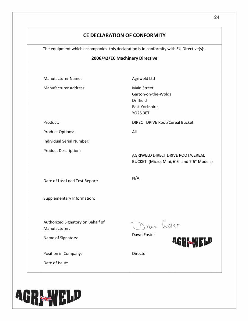
CE DECLARATION OF CONFORMITY
The equipment which accompanies this declaration is in conformity with EU Directive(s):-
2006/42/EC Machinery Directive
Manufacturer Name: Agriweld Ltd
Manufacturer Address: Main Street
Garton-on-the-Wolds
Driffield
East Yorkshire
YO25 3ET
Product: DIRECT DRIVE Root/Cereal Bucket
Product Options: All
Individual Serial Number:
Product Description: AGRIWELD DIRECT DRIVE ROOT/CEREAL
BUCKET. (Micro, Mini, 6’6” and 7’6” Models)
Date of Last Load Test Report:
N/A
Supplementary Information:
Authorized Signatory on Behalf of
Manufacturer:
Name of Signatory: Dawn Foster
Position in Company: Director
Date of Issue: