Opus One TM Superconducting Nanowire Single- Photon Detection System Installation and Operation Manual January 26, 2017 Quantum Opus, LLC 45211 Helm Street Plymouth, MI 48170-6023 USA 1-269-248-1004
Transcript
Opus OneTM
Superconducting Nanowire Single-Photon Detection SystemInstallation and Operation Manual
January 26, 2017
Quantum Opus, LLC
45211 Helm StreetPlymouth, MI 48170-6023USA1-269-248-1004
General InformationWarranty
This Quantum Opus product is warranted against defects in materials and workmanshipfor a period of one (1) year from the date of shipment.
Service
For warranty service or repair, this product must be returned to a Quantum Opus au-thorized service facility. Some components may be serviceable directly from the supplier.Contact Quantum Opus before returning this product for repair.
Proper Use
All Quantum Opus products are intended for use by properly trained users. In no eventshall Quantum Opus be liable for any direct, indirect, punitive, incidental, special conse-quential damages, to property or life, whatsoever arising out of or connected with the useor misuse of our products.
This document is provided by the copyright holders “as is” and any express or impliedwarranties, including, but not limited to, the implied warranties of merchantability andfitness for a particular purpose are disclaimed. In no event shall the copyright holder beliable for any direct, indirect, incidental, special, exemplary, or consequential damages (in-cluding, but not limited to, procurement of substitute goods or services; loss of use, data,or profits; or business interruption) however caused and on any theory of liability, whetherin contract, strict liability, or tort (including negligence or otherwise) arising in any wayout of the use of this document, even if advised of the possibility of such damage.
WARNINGA WARNING notice identifies a hazard. This type of notice identifies a procedure,practice, or similar, that, if not properly performed or adhered to, could resultin damage (possibly significant) to persons or property. Do not proceed past aWARNING notice until the indicated conditions are fully understood and met.If there is any question about proper performance of the procedure or practice,contact Quantum Opus support for guidance.
B
NOTEA NOTE notice identifies a procedure, practice, or similar that if not properlyperformed or adhered to, could result in degraded system performance, reducedsystem “up-time,” or increased frequency of system maintenance. Although ad-herence to a NOTE is not safety critical, adherence is required to ensure systemperformance meets specifications. If there is any question about proper perfor-mance of the procedure or practice, contact Quantum Opus support for guidance.
i
3
Opus One
Figure 1: Photo of a typical four-channel Opus Oneunit containing four superconductingnanowires, cryogenic vacuum system, and fiber optic couplers. Various configu-rations are available with up to 16 detector channels in the above 19-inch rackconfiguration (3U height). Specific options and configurations may vary.
4
1 IntroductionThe Opus Oneis a high-speed, high-efficiency, fiber-coupled, single-photon detection systemusing superconducting nanowire technology. The system can contain between one andsixteen nanowire detectors, depending on configuration.
1.1 Overview
Compressor
PressurizedNheliumcompressorNlines
Power
CoolingNwaterN
SRSNSIM900
OpusNOne
1
n
2vNvNv
vNvNv
vNvNv NanowireNcableBs/SMANMQMNDoubleQShielded
ThermometerCableNDB9NM/F
LightNinBFiber/
Power
GPIB
SIM922module
QOQAMPQSIMmoduleBs/
1
n
2vNvNv
vNvNv
NanowireNpulsesNoutBSMA/
1 2 nvNvNv
1 2 nvNvNv
ColdNheaddriveNcable
Compressor Unit
Opus One Unit
Electronics Unit
Figure 2: Nanowire system schematic showing Opus Onehead unit, electronics unit, andcompressor with all connections.
The nanowire system has three main physical components, as identified in Figure 2:
1. The “Electronics Unit” that provides system thermometry and nanowire device con-
5
Opus One
trol and monitoring.
2. The “Opus One Unit” consisting of the vacuum and cryogenic components, nanowiredetectors, and nanowire optical and electrical connections.
3. The “Compressor Unit” that provides the high-pressure, high-purity helium and valvecontrol signals to obtain and maintain the low temperatures required for supercon-ducting nanowire operation.
6
2 InstallationThis section covers unpacking and installing your new nanowire detector system.
WARNINGSeveral system components contain high-pressure helium gas. Follow manufac-turer recommendations for installation. Eye protection is recommended duringinstallation. Follow local regulations and recommendations for proper personalprotective equipment (PPE) when working with high pressure gases.
B
WARNINGEnsure the system has been powered off for 24 hours before opening the ventvalve or making changes to the high-pressure connections between the detectorhead and the compressor.
B
2.1 Preparation for Installation
Before unpacking your Opus One system head, the compressor must be installed. Carefullyconsider the placement of the compressor and Opus One head unit. For this discussion,refer Figure 2 on page 5.
WARNINGIt is normal for the high-pressure helium lines to move slightly during systemoperation. Ensure the lines do not rub on sharp corners or on other objects thatmay become damaged from abrasion with the metal tubing such as electricalwiring or water lines.
B
NOTEDistances over 3m between the detector head and compressor may reduce detectorperformance because of decreased system cooling power.
i
1. Determine compressor and high-pressure helium location appropriate for proper prox-imity to your water and power connections.
NOTEBecause of the polarization sensitivity of the nanowire devices, it is impor-tant to minimize uncontrolled polarization drift between your source and
i
7
Opus One
the detector unit. Polarization drift can be made worse with long opticalfibers, fibers that continually change position (e.g., due to vibration or aircurrents), or fibers that change temperature.
i
2. Determine the Opus One unit location appropriate for your source of photons, en-suring that the pressurized high-purity helium lines will move freely and will not beunder tension. Minimize the distance between your optical source and the detectorunit.
3. Determine the best location for the electronics unit (SIM900 plus associated mod-ules), noting that it is intended to be operated either directly above or below the OpusOne detector head to minimize the introduction of noise between the electronics andthe Opus One unit.
2.2 Compressor Unit Installation
WARNINGAs per manufacturer recommendations, inspect all gaskets and o-ring surfaces toensure they are present, undamaged, and clean. A missing or damaged o-ringcould result in rapid, catastrophic release of high-pressure helium. Do not useany lubricants on the connectors. Always ensure connectors are mated properlyto avoid any loss of high-purity helium.
B
WARNINGDo not install the helium lines to the detector head until instructed to do so inthe order given below. Installation of the helium lines in the wrong order, or tothe wrong ports, may require factory repair of the Opus One unit.
B
1. Establish the proper electrical and water connections to the compressor accordingto documentation provided separately by the compressor manufacturer. Be sure tocomply with all manufacturer recommendations and local laws, codes, and buildingrecommendations.
2. Perform any recommended compressor run testing. See provided compressor manu-facturer documentation.
3. After any required compressor run testing, install the high-pressure helium lines ontothe compressor SUPPLY and RETURN connections, as described in the compressormanufacturer documentation.
8
Opus One
2.3 Opus One Unit Installation
WARNINGDo not lift or position the detector head by putting force on the front panelconnectors or on the rear valve, port, high-pressure tubing connections, or wiringconnectors.
B
WARNINGDo not rest the unit, even temporarily, on its front (i.e., on the electrical andoptical connections) or rear (i.e., on the valve, port, high-pressure tubing connec-tions).
B
WARNINGDo not attempt to mount the detector head into a rack enclosure without bothsupport from both front and back rail flanges. Damage to the system is likely.
B
Refer to the diagram of the Opus One unit shown in Figure 3 on the next page for theprocedures in this section.
1. Determine how to properly lift the detector head. Avoid lifting by any valve, port,electrical, or tubing connections. As long as you avoid the tubing lines, you may liftby the central solid aluminum block at the rear of the unit, as shown in Figure 3 onthe next page.
2. Carefully remove the Opus One unit from its packaging. Note that the unit has asignificant fraction of its weight toward the back.
3. Remove any protective wrapping around the Opus One unit and on the front panel.
4. For rack-mount operation, contact Quantum Opus support for guidance on the se-lection of an appropriate shelf mount.
5. If desired, apply the provided adhesive feet near the corners of the bottom panel ofthe detector head. The head may be set temporarily on its top, bottom, right or leftsides to facilitate applying the feet.
6. Temporarily place the Opus One unit in a location near its operation location sothat, after the high-pressure helium lines are connected, it can be positioned into itsfinal installed location with minimal strain on the high-pressure helium connectionsat the rear of the unit.
7. The pressurized helium lines must be connected in the following order.
9
Opus One
Figure 3: Rear view of the Opus One detector unit showing a suggested lift point forinstallation.
a) Ensure the SUPPLY and RETURN lines are already connected to the compres-sor and properly labeled SUPPLY and RETURN.
b) If (optional) pressurized right-angle adapters are to be used, contact QuantumOpus for the proper installation procedure.
WARNINGUsing the improper method of connecting the helium lines, connectingin the improper order, or erroneously interchanging the RETURN andSUPPLY lines may result in permanent damage to the tubing lines ornecessitate service to the Opus One unit. Adhere to the followingprocedures carefully.
B
c) First, using the proper “three-wrench” procedure as described in the SumitomoSRDK Operations Manual (provided by Quantum Opus, upon request), connect
10
Opus One
the “RETURN” high-pressure helium line to the “RETURN” connector on therear of the Opus One unit.
d) Second, again using the proper “three-wrench” procedure, connect the “SUP-PLY” high-pressure helium line to the “SUPPLY” connector on the read of theOpus One unit.
e) Connect the provided electrical drive cable between the compressor and theOpus One unit.
11
3 Electronics Unit Installation
WARNINGThe Opus One devices and electronics are sensitive to Electrostatic Discharge(ESD). Ensure you are properly grounded before changing cable connections ofany type. Ensure that the QO-AMP-SIM modules are powered on and the“STATUS” light is illuminated green ( ) when connecting the SMA cables be-tween the QO-AMP-SIM module and the Opus One.
B
WARNINGDo not overtighten the SMA or optical connectors. Finger-tight connectionsare recommended for fiber connections. Slightly tighter than finger-tight con-nections are recommended for SMA connections. Overtightening the connectorsmay loosen the internal connectors in the Opus One unit or cause damage to theconnectors, damage to cables, or increased system losses and noise.
B
NOTEUse only the provided double-shielded SMA cables between the Opus One unitand the QO-AMP-SIM modules to reduce the possibility of increased electricallyinduced noise counts.
i
1. Depending on the options purchased with your system, various Stanford ResearchSystems SIM-compatible modules (including QO-AMP-SIM modules) have been pro-vided with your system. With the SIM900 power off, insert all desired modules firmlyinto the SIM900 rack, as per documentation on the SIM900 rack available from Stan-ford Research Systems at www.thinksrs.com. Note that, if installing fewer than eightQO-AMP-SIM modules, it is typically most convenient to place the QO-AMP-SIMmodules in the farthest right (highest numbered) slots to keep the SMA connectionsclose to the Opus One unit SMA connectors.
2. If seven or fewer QO-AMP-SIM modules are to be used, install the provided SIM922Diode Temperature Monitor into an unused slot in the SIM900 rack. If eight or moreQO-AMP-SIM modules are to be used, attach the provided 15-pin (DB15 male toDB15 female) extension cable between the rear of the SIM922 module and the rearDB15 connector labeled ”Remote SIM (Port 9)” on the SIM900 rack unit.
3. Attach the provided 9-pin (DB9 male to DB9 female) filter adapter to the upper DB9connector on the back of the SIM922 Diode Temperature Monitor.
4. Attach the provided 9-pin cable between the filter and the “Therm” connector on
12
Opus One
the rear of the Opus One unit.
5. Power on the SIM900 rack and ensure that the SIM922 module reads a voltage ofapproximately 0.6 Volts on both channel 1 and channel 2 thermometers. You mayneed to press the small “Units” button at the bottom of the SIM922 front panel toswitch to “V” from “K” to see the thermometer voltages.
6. At this time all QO-AMP-SIM modules should have their “STATUS” light illumi-nated green ( ). The green status light indicates a safe, standby mode for connectingand disconnecting the Opus One unit SMA cables.
7. With the SIM900 unit still powered and the QO-AMP-SIM status lights green, con-nect the Opus One to the QO-AMP-SIM modules using the provided 12-inch double-shielded SMA cables. For each detector, connect one cable from the “Electrical”SMA connector on the Opus One unit to the “NW” input on a corresponding QO-AMP-SIM module in the SIM900 rack. Tighten the SMA connectors slightly tighterthan finger tight using a small SMA wrench (desired torque should be 0.3 to 0.6 N·m,3 to 5 in·lbs).
8. Once all QO-AMP-SIM modules are connected to their respective nanowire connec-tors, the SIM900 rack may be powered down. All connections may be left in placewhen powering up and power down the SIM900.
13
4 System OperationThis chapter details the “Cool down” and “Warm up” procedures for the cryogenic com-ponents of the Opus One nanowire system.
WARNINGIf either the compressor or Opus One unit operate in a seemingly erratic or unsafemanner, turn off the power to the compressor and the electronics unit and contactQuantum Opus for additional help.
B
WARNINGWhenever using a vacuum pump to evacuate a system, ensure there is adequate“slack” in the pumping line to allow for line contraction (sometimes very signif-icant) during pumping. Inadequate line length can cause unsafe forces on thepump, pumping lines, or Opus One unit and can cause equipment to be damagedor to move in undesired ways (e.g., tip over, fall off of shelving).
B
4.1 Cool Down Procedure
The procedures in this chapter should be accomplished for first-time operation and re-peated any time that the system has been allowed to warm above approximately 45 Kelvin,for example in case of accidental power failure, cooling water loss, or intentional systemshutdown.
NOTEThe system should be in its warm state before starting this procedure to ensureproper cool down. A “warm” state is indicated on the SIM922 Diode TemperatureMonitor SIM module by both channel 1 and channel 2 thermometers readingabove 280 K. This state should be achieved within 24 hours after the system hasbeen powered off. For the system warm-up procedure, see Section 4.2 on page 16.
i
NOTEA vacuum pump that reaches a pressure below approximately 1 mbar (0.75 Torr)is required for the cool down procedure, but is not required for continuous op-eration. A dry, or oil-free, pump is preferred to prevent the possibility of oilbackstreaming that could contaminate the cryogenic system.
i
14
Opus One
WARNINGWhen closing the green vacuum valve (labeled “Valve”) on the rear of the OpusOne unit, do not overtighten. This valve should be close only until finger tight.Never use pliers or tools to close the valve. Using excessive force to close thevalve can permanently damage the valve mechanism.
B
The cool down procedure steps should be completed in the following order:
1. Evacuate the Opus One unit according to the following procedure.
a) Ensure the green vacuum valve (labeled “Valve”) on the rear of the Opus Oneunit is closed by gently applying clockwise torque. The valve should not turnunder light torque. Do not overtighten.
b) Remove the NW25 cap and o-ring from the vacuum port (labeled “Pump/Vent”)loosening the clamp screw and removing the clamp.
c) Inspect the o-ring to ensure it is dust-free and has no cracks or flaws. If so,replace the o-ring before proceeding.
d) Using the o-ring and clamp, connect the vacuum pump via an appropriate NW25vacuum tube (not provided) to the vacuum port and tighten the clamp securely.
e) Follow the vacuum pump manufacturer’s recommended procedure for startingthe pump and evacuating the pump tube.
f) Slowly open the vacuum valve on the Opus One unit. The valve is fully openonce rotated counterclockwise approximately two (2) full turns.
2. Ensure the compressor is ready for use, including turning on any required coolingwater or electrical breakers.
3. Turn on the electrical power to the compressor. The hum of the compressor and theapproximately 1 cycle-per-second “hiss” of the Opus One unit should begin immedi-ately. If the 1 cycle-per-second sound from the Opus One is not heard, turn off thecompressor and confirm that the helium line and electrical connections between theOpus One unit and the compressor are correct, as per Section 2.3.
4. Confirm that the temperature reading of the channel 1 thermometer on the SIM922Diode Temperature Monitor indicates the temperature has begun to decrease.
5. Wait until the temperature of the channel 1 thermometer drops below approximately50 K, then close the vent valve by turning the green valve knob clockwise until fingertight.
NOTEIf using a dry pump with strong pumping capabilities such as a turbo-molecular drag pump (i.e., “turbo” pump), you may choose to wait until
i
15
Opus One
the system is fully cold to close the green vacuum valve as there is low riskof backstreaming contaminants such as air or pump oil into the cryogenicspace of the Opus One unit.
i
6. Once the vacuum valve is closed you may disconnect the pumping line and turn offthe pump, according to the process recommended by the pump manufacturer.
7. Seal the NW25 Pump/Ventport using the NW25 o-ring, cap, and clamp.
8. Wait until the temperature of the channel 2 thermometer (on the SIM922 DiodeTemperature Monitor) indicates the system is at is “base” temperature (typicallybelow 2.7 K). The cool-down takes approximately three (3) hours from the time thecompressor is turned on.
9. The Opus One devices are now ready to be used. Refer to Section 5.1.
4.2 Warm Up Procedure
WARNINGEnsure the system has been turned off for a minimum of 24 hours before openingthe vent valve or making changes to any of the high-pressure helium line con-nections. Unsafe conditions can be created if the system is vented or the heliumlines are disconnected from the compressor or Opus One unit while the eitherinternal temperature is 280 K.
B
16
5 Detector OperationThis chapter describes the process of turning on the detectors and describes basic frontpanel commands for the QO-AMP-SIM electronic control modules.
5.1 Setting Up the Detectors
NOTEThe output pulses from the nanowire electronics are positive pulses of amplitude150 mV or higher. If negative pulses are required, use of a passive pulse invertersuch as the PicoQuant SI100 is recommended.
i
The superconducting nanowire detectors operate by applying a DC bias current slightlybelow a threshold “switching current.” Upon absorption of a photon, the nanowire switchesfrom a low-resistance superconducting state to a high-resistance “normal,” or non-super-conducting, state resulting in rapid increase in output voltage. The detector recoversduring a “dead-time” before it is ready to detect another photon. The bias current to theeach detector is supplied through the electrical connections to the “NW” port of the re-spective channel’s QO-AMP-SIM module. The voltage pulses generated by photodetectionare amplified by the QO-AMP-SIM module and output from the “OUT” ports. Beforebiasing a nanowire, first make sure it is connected to a QO-AMP-SIM module as describedin Chapter 3 and that the module is in standby mode (indicated by a green light). Use thefollowing steps to bias and operate the device.
1. Connect the QO-AMP-SIM “OUT” SMA connector to a counter with a 50 Ω inputimpedance set to 50 mV threshold.
2. The counter should read near zero counts per second at this point. If you are seeinghigh counts, there is likely a ground issue or electrical noise from the lab environment.Please see Chapter 6 for advice on how to correct this.
3. Press and hold the plus (+) and minus (−) buttons until the light turns yellow.Upon release of the buttons, the QO-AMP-SIM will autobias the device to a highdark rate and the light will go off.
NOTEThe electronics perform an “autoreset” operation upon detecting a latchcondition on the device. If the count rate of the device is too high (due toa high bias current, too strong optical flux, or grounding/noise issue) thelight will blink continuously as the electronics continually attempt to resetthe device. Simply decreasing the bias by repeatedly pressing the minus
i
17
Opus One
(−) button should stop this. The autoreset function can be disabled byserial command if desired.
i
4. Reduce the dark count to ∼100 to 200 counts per second by repeatedly pressing theminus (−) button. The nanowire should now be ready for use. If you are unable toreduce the dark counts to this level, there is most likely a grounding/electrical noiseissue. Please see the troubleshooting advice in Chapter 6.
NOTEThe nanowires are polarization sensitive and will only achieve peak detectionefficiency for photons at the optimal polarization. Photons polarized orthogonalto optimum polarization will be detected with approximately 50% lower efficiency.
i
5.2 Front Panel Command Reference
The QO-AMP-SIM modules perform the basic control tasks for nanowire operation, andcan do so without serial control via front-panel operation. Below is the list of operationswhich may be performed using only front-panel control.
Bias ON/OFF Press the red ( ) button to turn the bias current on or off. When the biasis turned on, the device bias current will be set to the most recent bias setpoint sincethe module has been powered up. The bias resets to zero upon power up.
Increase Bias Press the plus (+) button to increase the bias current by one step. Thebias increment is approximately 0.4% of the present bias setting. Holding the buttonwill rapidly increase the bias.
Decrease Bias Press the minus (−) button to decrease the bias current by one step (inDAC units). The bias decrement is approximately 0.4% of the present bias setting.Holding the button will rapidly decrease the bias.
Autobias Press and hold both the plus (+) and minus (−) buttons until the indicatorlight turns yellow to autobias the nanowire. The bias current will be ramped up untilthe nanowire enters a latched state, the bias is then decreased by approximately 6%so the device can operate with high efficiency near the maximum switching current.Note that this bias point should be considered a good starting point for biasing thedevice but is unlikely to be the optimum point for your application. Also note thatbecause of slight differences in the measured switching current the autobias functionmay not return to the same bias point each time it is run.
Store Bias With the bias enabled, press and hold the red ( ) and plus (+) buttons tostore the current bias level into nonvolatile memory for later use. This stored valueis retained during power off.
18
Opus One
Load Bias With the bias disabled, press and hold the red ( ) and minus (−) buttons torevert the bias level to the value stored in nonvolatile memory.
19
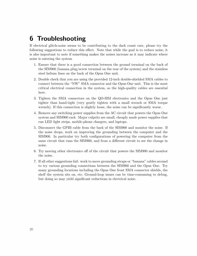
6 TroubleshootingIf electrical glitch-noise seems to be contributing to the dark count rate, please try thefollowing suggestions to reduce this effect. Note that while the goal is to reduce noise, itis also important to note if something makes the noises increase as it may indicate wherenoise is entering the system
1. Ensure that there is a good connection between the ground terminal on the back ofthe SIM900 (banana plug/screw terminal on the rear of the system) and the stainlesssteel helium lines on the back of the Opus One unit.
2. Double check that you are using the provided 12-inch double-shielded SMA cables toconnect between the “NW” SMA connector and the Opus One unit. This is the mostcritical electrical connection in the system, so the high-quality cables are essentialhere.
3. Tighten the SMA connectors on the QO-SIM electronics and the Opus One justtighter than hand-tight (very gently tighten with a small wrench or SMA torquewrench). If this connection is slightly loose, the noise can be significantly worse.
4. Remove any switching power supplies from the AC circuit that powers the Opus Onesystem and SIM900 rack. Major culprits are small, cheaply made power supplies thatrun LED light strips, mobile-phone chargers, and laptops.
5. Disconnect the GPIB cable from the back of the SIM900 and monitor the noise. Ifthe noise drops, work on improving the grounding between the computer and theSIM900. In particular try both configurations of powering the computer from thesame circuit that runs the SIM900, and from a different circuit to see the change innoise.
6. Try moving other electronics off of the circuit that powers the SIM900 and monitorthe noise.
7. If all other suggestions fail: work to move grounding straps or “banana” cables aroundto try various grounding connections between the SIM900 and the Opus One. Trymany grounding locations including the Opus One front SMA connector shields, theshelf the system sits on, etc. Ground-loop issues can be time-consuming to debug,but doing so may yield significant reductions in electrical noise.