156
Oracle® Communications Interactive Session Recorder Installation Guide Release 5.1 Formerly Net-Net Interactive Session Recorder December 2015

Oracle® Communications Interactive Session RecorderInstallation Guide
Release 5.1
Formerly Net-Net Interactive Session Recorder
December 2015

Copyright ©2015, 2004, Oracle and/or its affiliates. All rights reserved.
This software and related documentation are provided under a license agreement containing restrictions on use and disclosure and are protected by intellectual property laws. Except as expressly permitted in your license agreement or allowed by law, you may not use, copy, reproduce, translate, broadcast, modify, license, transmit, distribute, exhibit, perform, publish, or display any part, in any form, or by any means. Reverse engineering, disassembly, or decompilation of this software, unless required by law for interoperability, is prohibited.
The information contained herein is subject to change without notice and is not warranted to be error-free. If you find any errors, please report them to us in writing.
If this is software or related documentation that is delivered to the U.S. Government or anyone licensing it on behalf of the U.S. Government, the following notice is applicable:
U.S. GOVERNMENT END USERS: Oracle programs, including any operating system, integrated software, any programs installed on the hardware, and/or documentation, delivered to U.S. Government end users are "commercial computer software" pursuant to the applicable Federal Acquisition Regulation and agency-specific supplemental regulations. As such, use, duplication, disclosure, modification, and adaptation of the programs, including any operating system, integrated software, any programs installed on the hardware, and/or documentation, shall be subject to license terms and license restrictions applicable to the programs. No other rights are granted to the U.S. Government.
This software or hardware is developed for general use in a variety of information management applications. It is not developed or intended for use in any inherently dangerous applications, including applications that may create a risk of personal injury. If you use this software or hardware in dangerous applications, then you shall be responsible to take all appropriate fail-safe, backup, redundancy, and other measures to ensure its safe use. Oracle Corporation and its affiliates disclaim any liability for any damages caused by use of this software or hardware in dangerous applications.
Oracle and Java are registered trademarks of Oracle and/or its affiliates. Other names may be trademarks of their respective owners.
Intel and Intel Xeon are trademarks or registered trademarks of Intel Corporation. All SPARC trademarks are used under license and are trademarks or registered trademarks of SPARC International, Inc. AMD, Opteron, the AMD logo, and the AMD Opteron logo are trademarks or registered trademarks of Advanced Micro Devices. UNIX is a registered trademark of The Open Group.
This software or hardware and documentation may provide access to or information on content, products, and services from third parties. Oracle Corporation and its affiliates are not responsible for and expressly disclaim all warranties of any kind with respect to third-party content, products, and services. Oracle Corporation and its affiliates will not be responsible for any loss, costs, or damages incurred due to your access to or use of third-party content, products, or services.

Release 5.1 Oracle Communications Interactive Session Recorder Installation Guide iii
Contents
About this Guide . . . . . . . . . . . . . . . . . . . . . . . . . . . . . . . . . . . . . . . . . . . . . . . . . . . 9
Overview . . . . . . . . . . . . . . . . . . . . . . . . . . . . . . . . . . . . . . . . . . . . . . . . . . . . . . . . . . . . . . . . . . . . . . . . .9
ISR Releases. . . . . . . . . . . . . . . . . . . . . . . . . . . . . . . . . . . . . . . . . . . . . . . . . . . . . . . . . . . . . . . . . . . .9
Related Documentation . . . . . . . . . . . . . . . . . . . . . . . . . . . . . . . . . . . . . . . . . . . . . . . . . . . . . . . . . . . .10
Revision History . . . . . . . . . . . . . . . . . . . . . . . . . . . . . . . . . . . . . . . . . . . . . . . . . . . . . . . . . . . . . . . . . .10
1 Overview . . . . . . . . . . . . . . . . . . . . . . . . . . . . . . . . . . . . . . . . . . . . . . . . . . . . . . . . . 13
Introduction . . . . . . . . . . . . . . . . . . . . . . . . . . . . . . . . . . . . . . . . . . . . . . . . . . . . . . . . . . . . . . . . . . . . .13
About the ISR . . . . . . . . . . . . . . . . . . . . . . . . . . . . . . . . . . . . . . . . . . . . . . . . . . . . . . . . . . . . . . . . . . . .13
2 Hardware/Software Requirements . . . . . . . . . . . . . . . . . . . . . . . . . . . . . . . . . . . 15
Introduction . . . . . . . . . . . . . . . . . . . . . . . . . . . . . . . . . . . . . . . . . . . . . . . . . . . . . . . . . . . . . . . . . . . . .15
Hardware . . . . . . . . . . . . . . . . . . . . . . . . . . . . . . . . . . . . . . . . . . . . . . . . . . . . . . . . . . . . . . . . . . . . . . .15
CIS & RSS Certified Hardware . . . . . . . . . . . . . . . . . . . . . . . . . . . . . . . . . . . . . . . . . . . . . . . . . . . .15
For CIS Server . . . . . . . . . . . . . . . . . . . . . . . . . . . . . . . . . . . . . . . . . . . . . . . . . . . . . . . . . . . . .15
For RSS Server . . . . . . . . . . . . . . . . . . . . . . . . . . . . . . . . . . . . . . . . . . . . . . . . . . . . . . . . . . . . .16
RAID Configuration. . . . . . . . . . . . . . . . . . . . . . . . . . . . . . . . . . . . . . . . . . . . . . . . . . . . . . . . . . . . .17
Software . . . . . . . . . . . . . . . . . . . . . . . . . . . . . . . . . . . . . . . . . . . . . . . . . . . . . . . . . . . . . . . . . . . . . . . .18
ISR Software . . . . . . . . . . . . . . . . . . . . . . . . . . . . . . . . . . . . . . . . . . . . . . . . . . . . . . . . . . . . . . . . . .18
ISR Dashboard Requirements . . . . . . . . . . . . . . . . . . . . . . . . . . . . . . . . . . . . . . . . . . . . . . . . . . . . .18
Virtual Machine Default Resource Configurations . . . . . . . . . . . . . . . . . . . . . . . . . . . . . . . . . . . . .19
Sample Implementation Diagrams . . . . . . . . . . . . . . . . . . . . . . . . . . . . . . . . . . . . . . . . . . . . . . . . . . .22
Single Site-Single Server ISR/SBC Implementation . . . . . . . . . . . . . . . . . . . . . . . . . . . . . . . . . . . .22
Single Site-2RSS ISR/SBC Implementation . . . . . . . . . . . . . . . . . . . . . . . . . . . . . . . . . . . . . . . . . .23
Dual Site Redundant ISR/SBC Implementation . . . . . . . . . . . . . . . . . . . . . . . . . . . . . . . . . . . . . . .24
3 Installing the CIS Software. . . . . . . . . . . . . . . . . . . . . . . . . . . . . . . . . . . . . . . . . . 25
Introduction . . . . . . . . . . . . . . . . . . . . . . . . . . . . . . . . . . . . . . . . . . . . . . . . . . . . . . . . . . . . . . . . . . . . .25

iv Oracle Communications Interactive Session Recorder Installation Guide Release 5.1
What is CIS?. . . . . . . . . . . . . . . . . . . . . . . . . . . . . . . . . . . . . . . . . . . . . . . . . . . . . . . . . . . . . . . . . . . . .25
Before You Begin . . . . . . . . . . . . . . . . . . . . . . . . . . . . . . . . . . . . . . . . . . . . . . . . . . . . . . . . . . . . . . . . .25
VMware Enterprise vSphere Hypervisor (ESXi) . . . . . . . . . . . . . . . . . . . . . . . . . . . . . . . . . . . . . . .26
What is vSphere Hypervisor?. . . . . . . . . . . . . . . . . . . . . . . . . . . . . . . . . . . . . . . . . . . . . . . . . . . . . .26
Installing vSphere Hypervisor . . . . . . . . . . . . . . . . . . . . . . . . . . . . . . . . . . . . . . . . . . . . . . . . . . . . .26
Configuring vSphere Hypervisor . . . . . . . . . . . . . . . . . . . . . . . . . . . . . . . . . . . . . . . . . . . . . . . . . . .27
VMware vSphere Client . . . . . . . . . . . . . . . . . . . . . . . . . . . . . . . . . . . . . . . . . . . . . . . . . . . . . . . . . . .28
What is vSphere Client? . . . . . . . . . . . . . . . . . . . . . . . . . . . . . . . . . . . . . . . . . . . . . . . . . . . . . . . . . .28
Installing vSphere Client . . . . . . . . . . . . . . . . . . . . . . . . . . . . . . . . . . . . . . . . . . . . . . . . . . . . . . . . .28
Configuring your vSphere ESXi Host . . . . . . . . . . . . . . . . . . . . . . . . . . . . . . . . . . . . . . . . . . . . . . . .32
Assigning Network Time Server . . . . . . . . . . . . . . . . . . . . . . . . . . . . . . . . . . . . . . . . . . . . . . . . . . .33
Configuring the Local Network . . . . . . . . . . . . . . . . . . . . . . . . . . . . . . . . . . . . . . . . . . . . . . . . . . . . .35
Adding Additional Storage Array to CIS . . . . . . . . . . . . . . . . . . . . . . . . . . . . . . . . . . . . . . . . . . . . .38
Adding the Datastore to the ESXi Storage Pool . . . . . . . . . . . . . . . . . . . . . . . . . . . . . . . . . . . . . . .38
Installing the ISR Index. . . . . . . . . . . . . . . . . . . . . . . . . . . . . . . . . . . . . . . . . . . . . . . . . . . . . . . . . . . .42
Deploying the Index VM . . . . . . . . . . . . . . . . . . . . . . . . . . . . . . . . . . . . . . . . . . . . . . . . . . . . . . . . .42
Network Mapping. . . . . . . . . . . . . . . . . . . . . . . . . . . . . . . . . . . . . . . . . . . . . . . . . . . . . . . . . . . .45
ISR Dashboard . . . . . . . . . . . . . . . . . . . . . . . . . . . . . . . . . . . . . . . . . . . . . . . . . . . . . . . . . . . . . . . . . . .48
Deploying the Dashboard VM . . . . . . . . . . . . . . . . . . . . . . . . . . . . . . . . . . . . . . . . . . . . . . . . . . . . .48
Configuring the VM Network Addresses. . . . . . . . . . . . . . . . . . . . . . . . . . . . . . . . . . . . . . . . . . . . . .52
Configure Automatic Start of the VMs . . . . . . . . . . . . . . . . . . . . . . . . . . . . . . . . . . . . . . . . . . . . . . .54
Configuring the Time zone on a CIS Host . . . . . . . . . . . . . . . . . . . . . . . . . . . . . . . . . . . . . . . . .56
4 Installing the RSS Software . . . . . . . . . . . . . . . . . . . . . . . . . . . . . . . . . . . . . . . . . 57
Introduction . . . . . . . . . . . . . . . . . . . . . . . . . . . . . . . . . . . . . . . . . . . . . . . . . . . . . . . . . . . . . . . . . . . . .57
What is RSS? . . . . . . . . . . . . . . . . . . . . . . . . . . . . . . . . . . . . . . . . . . . . . . . . . . . . . . . . . . . . . . . . . . . .57
Installing RSS . . . . . . . . . . . . . . . . . . . . . . . . . . . . . . . . . . . . . . . . . . . . . . . . . . . . . . . . . . . . . . . . . . . .57
Loading RSS Software . . . . . . . . . . . . . . . . . . . . . . . . . . . . . . . . . . . . . . . . . . . . . . . . . . . . . . . . . . .57
Configuring the Serial Console Settings . . . . . . . . . . . . . . . . . . . . . . . . . . . . . . . . . . . . . . . . . .58
Configuring RSS Networking . . . . . . . . . . . . . . . . . . . . . . . . . . . . . . . . . . . . . . . . . . . . . . . . . . . . .59
Before You Begin. . . . . . . . . . . . . . . . . . . . . . . . . . . . . . . . . . . . . . . . . . . . . . . . . . . . . . . . . . . .59
Configure Primary Network Interface . . . . . . . . . . . . . . . . . . . . . . . . . . . . . . . . . . . . . . . . . . . .60
Configuring Media NIC . . . . . . . . . . . . . . . . . . . . . . . . . . . . . . . . . . . . . . . . . . . . . . . . . . . . . . .63
Finalize ISR Configuration. . . . . . . . . . . . . . . . . . . . . . . . . . . . . . . . . . . . . . . . . . . . . . . . . . . . .63
Configuring the Time zone. . . . . . . . . . . . . . . . . . . . . . . . . . . . . . . . . . . . . . . . . . . . . . . . . . . . .65
Configuring NTP Services . . . . . . . . . . . . . . . . . . . . . . . . . . . . . . . . . . . . . . . . . . . . . . . . . . . . .67
Applying RSS License . . . . . . . . . . . . . . . . . . . . . . . . . . . . . . . . . . . . . . . . . . . . . . . . . . . . . . . . . . . . .68
Verify RSS License Applied . . . . . . . . . . . . . . . . . . . . . . . . . . . . . . . . . . . . . . . . . . . . . . . . . . .69

Release 5.1 Oracle Communications Interactive Session Recorder Installation Guide v
Applying Converter License . . . . . . . . . . . . . . . . . . . . . . . . . . . . . . . . . . . . . . . . . . . . . . . . . . . . . . . .70
5 Post-Install Verification and Configuration . . . . . . . . . . . . . . . . . . . . . . . . . . . . 73
Introduction . . . . . . . . . . . . . . . . . . . . . . . . . . . . . . . . . . . . . . . . . . . . . . . . . . . . . . . . . . . . . . . . . . . . .73
Verifying Connectivity Between the RSS and the Index VM . . . . . . . . . . . . . . . . . . . . . . . . . . . . .73
Testing Connectivity . . . . . . . . . . . . . . . . . . . . . . . . . . . . . . . . . . . . . . . . . . . . . . . . . . . . . . . . . . . .73
Logging Into ISR Dashboard . . . . . . . . . . . . . . . . . . . . . . . . . . . . . . . . . . . . . . . . . . . . . . . . . . . . . .74
Navigation Icons. . . . . . . . . . . . . . . . . . . . . . . . . . . . . . . . . . . . . . . . . . . . . . . . . . . . . . . . . . . . .75
Configuring the ISR for Recording a Call. . . . . . . . . . . . . . . . . . . . . . . . . . . . . . . . . . . . . . . . . . . . .76
Add Site for RSS Server. . . . . . . . . . . . . . . . . . . . . . . . . . . . . . . . . . . . . . . . . . . . . . . . . . . . . . . . . .76
Add the RSS to a Site . . . . . . . . . . . . . . . . . . . . . . . . . . . . . . . . . . . . . . . . . . . . . . . . . . . . . . . . . . . .78
Add a Session Agent . . . . . . . . . . . . . . . . . . . . . . . . . . . . . . . . . . . . . . . . . . . . . . . . . . . . . . . . . . . .82
6 Setting up a Test Call. . . . . . . . . . . . . . . . . . . . . . . . . . . . . . . . . . . . . . . . . . . . . . . 87
Introduction . . . . . . . . . . . . . . . . . . . . . . . . . . . . . . . . . . . . . . . . . . . . . . . . . . . . . . . . . . . . . . . . . . . . .87
Configuring a Route (Conference Mode Recording) . . . . . . . . . . . . . . . . . . . . . . . . . . . . . . . . . . . .87
Setting Up a Softphone . . . . . . . . . . . . . . . . . . . . . . . . . . . . . . . . . . . . . . . . . . . . . . . . . . . . . . . . . . . .90
Installing and Configuring the Softphone . . . . . . . . . . . . . . . . . . . . . . . . . . . . . . . . . . . . . . . . . . . .90
Making the First Call. . . . . . . . . . . . . . . . . . . . . . . . . . . . . . . . . . . . . . . . . . . . . . . . . . . . . . . . . . . . . .93
Before You Begin. . . . . . . . . . . . . . . . . . . . . . . . . . . . . . . . . . . . . . . . . . . . . . . . . . . . . . . . . . . . . . .93
Verifying Call Recording/Playback Using the Dashboard. . . . . . . . . . . . . . . . . . . . . . . . . . . . . . . .95
A CIS Index Replication . . . . . . . . . . . . . . . . . . . . . . . . . . . . . . . . . . . . . . . . . . . . . . 99
CIS Index Replication . . . . . . . . . . . . . . . . . . . . . . . . . . . . . . . . . . . . . . . . . . . . . . . . . . . . . . . . . . . .100
Configuring Circular Replication. . . . . . . . . . . . . . . . . . . . . . . . . . . . . . . . . . . . . . . . . . . . . . . .100
B Mounting a Second RSS Drive for Recordings . . . . . . . . . . . . . . . . . . . . . . . . . 105
Preparing and Mounting a New Second RSS Drive . . . . . . . . . . . . . . . . . . . . . . . . . . . . . . . . . . .105
Mounting an Existing Pre-Formatted Second RSS Drive . . . . . . . . . . . . . . . . . . . . . . . . . . . . . . .105
Editing the vmgConfig.xml File. . . . . . . . . . . . . . . . . . . . . . . . . . . . . . . . . . . . . . . . . . . . . . . . . . .106
C Configuring RAID on the CIS and RSS Servers . . . . . . . . . . . . . . . . . . . . . . . 109
Configuring RAID On the HP DL360 Gen8 Server . . . . . . . . . . . . . . . . . . . . . . . . . . . . . . . . . . . .109
Configuring RAID On the HP DL360 G7 Server . . . . . . . . . . . . . . . . . . . . . . . . . . . . . . . . . . . . . .110

vi Oracle Communications Interactive Session Recorder Installation Guide Release 5.1
D CIS Troubleshooting . . . . . . . . . . . . . . . . . . . . . . . . . . . . . . . . . . . . . . . . . . . . . . 113
vSphere Hypervisor . . . . . . . . . . . . . . . . . . . . . . . . . . . . . . . . . . . . . . . . . . . . . . . . . . . . . . . . . . . . . .113
Index Virtual Machine. . . . . . . . . . . . . . . . . . . . . . . . . . . . . . . . . . . . . . . . . . . . . . . . . . . . . . . . . . . .114
Dashboard Virtual Machine . . . . . . . . . . . . . . . . . . . . . . . . . . . . . . . . . . . . . . . . . . . . . . . . . . . . . . .115
CIS Networking . . . . . . . . . . . . . . . . . . . . . . . . . . . . . . . . . . . . . . . . . . . . . . . . . . . . . . . . . . . . . . . . .116
E vmgConfig.xml Parameters . . . . . . . . . . . . . . . . . . . . . . . . . . . . . . . . . . . . . . . . 119
F Selective Call Recording/SIPREC . . . . . . . . . . . . . . . . . . . . . . . . . . . . . . . . . . . 127
What is SIPREC?. . . . . . . . . . . . . . . . . . . . . . . . . . . . . . . . . . . . . . . . . . . . . . . . . . . . . . . . . . . . . . . .127
License/Hardware Requirements . . . . . . . . . . . . . . . . . . . . . . . . . . . . . . . . . . . . . . . . . . . . . . . . . . .127
How it Works . . . . . . . . . . . . . . . . . . . . . . . . . . . . . . . . . . . . . . . . . . . . . . . . . . . . . . . . . . . . . . . . . . .127
Configuring SIPREC . . . . . . . . . . . . . . . . . . . . . . . . . . . . . . . . . . . . . . . . . . . . . . . . . . . . . . . . . . . . .129
Session Recording Server (SRS) . . . . . . . . . . . . . . . . . . . . . . . . . . . . . . . . . . . . . . . . . . . . . . . . . .129
Session Recording Group. . . . . . . . . . . . . . . . . . . . . . . . . . . . . . . . . . . . . . . . . . . . . . . . . . . . . . . .129
Load Balancing. . . . . . . . . . . . . . . . . . . . . . . . . . . . . . . . . . . . . . . . . . . . . . . . . . . . . . . . . . . . .130
Session Recording Group within Logical Remote Entities . . . . . . . . . . . . . . . . . . . . . . . . . . .130
Selective Recording . . . . . . . . . . . . . . . . . . . . . . . . . . . . . . . . . . . . . . . . . . . . . . . . . . . . . . . . . . . .131
High Availability (HA) Support. . . . . . . . . . . . . . . . . . . . . . . . . . . . . . . . . . . . . . . . . . . . . . . . . . .131
Single SRS . . . . . . . . . . . . . . . . . . . . . . . . . . . . . . . . . . . . . . . . . . . . . . . . . . . . . . . . . . . . . . . .131
SIPREC Configuration Procedure . . . . . . . . . . . . . . . . . . . . . . . . . . . . . . . . . . . . . . . . . . . . . . . . .131
Session-recording-server Attribute. . . . . . . . . . . . . . . . . . . . . . . . . . . . . . . . . . . . . . . . . . . . . .132
Session-recording-group Attribute (for HA only) . . . . . . . . . . . . . . . . . . . . . . . . . . . . . . . . . .133
Realm-config Attribute. . . . . . . . . . . . . . . . . . . . . . . . . . . . . . . . . . . . . . . . . . . . . . . . . . . . . . .134
Session-agent Attribute . . . . . . . . . . . . . . . . . . . . . . . . . . . . . . . . . . . . . . . . . . . . . . . . . . . . . .135
Sip-interface Attribute . . . . . . . . . . . . . . . . . . . . . . . . . . . . . . . . . . . . . . . . . . . . . . . . . . . . . . .136
Metadata Contents . . . . . . . . . . . . . . . . . . . . . . . . . . . . . . . . . . . . . . . . . . . . . . . . . . . . . . . . . . . . .137
Show Commands for Recording Sessions . . . . . . . . . . . . . . . . . . . . . . . . . . . . . . . . . . . . . . . . . . .138
Show rec . . . . . . . . . . . . . . . . . . . . . . . . . . . . . . . . . . . . . . . . . . . . . . . . . . . . . . . . . . . . . . . . . .138
Show rec redundancy . . . . . . . . . . . . . . . . . . . . . . . . . . . . . . . . . . . . . . . . . . . . . . . . . . . . . . . .139
Codec Negotiation . . . . . . . . . . . . . . . . . . . . . . . . . . . . . . . . . . . . . . . . . . . . . . . . . . . . . . . . . . . . . . .140
SIPREC Call Flows . . . . . . . . . . . . . . . . . . . . . . . . . . . . . . . . . . . . . . . . . . . . . . . . . . . . . . . . . . . . . .141
Selective Recording . . . . . . . . . . . . . . . . . . . . . . . . . . . . . . . . . . . . . . . . . . . . . . . . . . . . . . . . . . . .141
Normal Call (recording required) . . . . . . . . . . . . . . . . . . . . . . . . . . . . . . . . . . . . . . . . . . . . . . .141
Sample SDP and Metadata . . . . . . . . . . . . . . . . . . . . . . . . . . . . . . . . . . . . . . . . . . . . . . . . . . . .142
Normal Call (recording not required). . . . . . . . . . . . . . . . . . . . . . . . . . . . . . . . . . . . . . . . . . . .144
Early Media Call (recording not required) . . . . . . . . . . . . . . . . . . . . . . . . . . . . . . . . . . . . . . . .145
REFER Pass-Through Call (REFER handled by User Agent). . . . . . . . . . . . . . . . . . . . . . . . .146
REFER Call (REFER handled by ESD). . . . . . . . . . . . . . . . . . . . . . . . . . . . . . . . . . . . . . . . . .147

Release 5.1 Oracle Communications Interactive Session Recorder Installation Guide vii
SRS Indicates Busy in Call (recording not required) . . . . . . . . . . . . . . . . . . . . . . . . . . . . . . . .149
G Installing the Remote Archiver Webservice . . . . . . . . . . . . . . . . . . . . . . . . . . . 151
Introduction . . . . . . . . . . . . . . . . . . . . . . . . . . . . . . . . . . . . . . . . . . . . . . . . . . . . . . . . . . . . . . . . . . . .151
Remote Archival Webservice Platform Requirements . . . . . . . . . . . . . . . . . . . . . . . . . . . . . . . . .151
Deploying the Remote Archival Webservice VM . . . . . . . . . . . . . . . . . . . . . . . . . . . . . . . . . . . . .151
H Configuring An NFS Share For Archival . . . . . . . . . . . . . . . . . . . . . . . . . . . . . 153
Introduction . . . . . . . . . . . . . . . . . . . . . . . . . . . . . . . . . . . . . . . . . . . . . . . . . . . . . . . . . . . . . . . . . . . .153

viii Oracle Communications Interactive Session Recorder Installation Guide Release 5.1

Release 5.1 Oracle Communications Interactive Session Recorder Installation Guide 9
About this Guide
Overview
The Interactive Session Recorder Installation Guide provides information about:
• Overview of the Interactive Session Recorder (ISR) release features
• Hardware/Software Requirements/Recommendations
• Storage Considerations
• Control and Index Server (CIS) Installation
• Record and Store Server (RSS) Installation
• Post-install and Verification Procedures
• Making the First Call
• Additional Advanced Topics (Appendices)
ISR Releases The following Session Director (SD) products are certified for use with the ISR software:
• C-Series (3000/4000) SDs
• E-Series (2600) SDs
• Application Session Controller (ASC)
Note: For more information on the C-Series, E-Series, and ASC hardware, see Oracle’s applicable hardware documentation.

ABOUT THIS GUIDE
10 Oracle Communications Interactive Session Recorder Installation Guide Release 5.1
Related Documentation
The following table lists related documents.
Document Name Document Description
Interactive Session Recorder Release Note
Contains information about new ISR features and fixed issues in the current release of the ISR.
Interactive Session Recorder User’s Guide
Contains information about using the ISR Dashboard for all levels of users. Provides information about viewing, playing, deleting recordings, running reports, managing user profiles (Super User, Account Administrator, and Tenant Administrator only).
Interactive Session Recorder Administrator Guide
Contains information about using the ISR Dashboard for the Administrator level user (Super User, Account Administrator, and Tenant Administrator). Provides information about creating and managing accounts, routes, and users. Also provides information about configuring the ISR, running reports, and viewing active calls.
Interactive Session Recorder API Reference Guide
Contains information about Methods for Recording, VoiceXML Commands, representational state transfer (REST) application programming interface (API), Recording File Types/Formats Supported, Return Codes, sendIPCRCommand.jsp Subdialog, Advanced Options, Troubleshooting.
Interactive Session Recorder Monitoring Guide
Contains information about installing and configuring the ISR Monitor. It also includes the Monitor database schema as well as the Monitor MIB.
Interactive Session Recorder Remote Archival Web Services Reference Guide
Contains information about the Remote Archival Web Service, its Control methods, WSDL definitions, DataType Definitions, sample responses to requests, and importing the Remote Archival Web Service’s certificate into the client keystore.
Revision History
This section contains the revision history for this document.
Date Revision Number Description
July 31, 2013 Revision 1.00 • Initial release of the ISR 5.1 software.
December 2, 2013 Revision 1.01 • Adds the Configuring the Timezone on a CIS Host section to Chapter 3, Installing the CIS software.
• Adds a note that the default password must be changed upon initial login.
December 16, 2013
Revision 1.02 • Removes inaccurate version and build information from some screenshots.

ABOUT THIS GUIDE
Release 5.1 Oracle Communications Interactive Session Recorder Installation Guide 11
February 27, 2014 Revision 1.03 • Corrects the product name on the title page.• Adds a step to restart the ISR process in the
Finalize ISR Configuration section.• Updates Step 1 in the Configuring NTP Services
section to reflect the correct prompt that displays when the config box action is executed.
• Updates the supported Hypervisor version number.• Updates the supported OS that VMs use.• Updates the supported MySQL Server version.• Corrects the directory name in which to view MySQL
Server logs.• Corrects the directory name where Dashboard VM
log files can be accessed.• Updates the instructions for adding a separate CIS
network.
March 7, 2014 Revision 1.04 • Adds Appendix G Installing the Remote Archiver Webservice.
April 18, 2014 Revision 1.05 • Corrects various typographical errors.• Adds “Configuring the Serial Console Settings” to
Chapter 4, Installing the RSS Software.
May 16, 2014 Revision 1.06 • Corrects a typographical error.• Replaces NN-ISR with ISR.
August 29, 2014 Revision 1.07 • Updates the Configuring Circular Replication procedure.
• Corrects the path for the production.log.• Modifies “Configuring the VM Network Address”.
January 5, 2015 Revision 1.10 • Adds Appendix H Configuring An NFS Share For Archival.
May 1, 2015 Revision 1.20 • Updates the “CIS and RSS Certified Hardware” section.
• Corrects various typographical errors.• Updates “RAID Configuration” section and
separates it into two sections: “Configuring RAID on the HP DL360 G8” and “Configuring RAID on the HP DL360 G7”.
• Adds “VM Default Resource Configuration” section.• Updates information in the “CIS Troubleshooting”
chapter.• Updates “ISR Dashboards” section.• Updates “CIS Index Replication” procedures.• Updates “Installing the CIS Software” procedures.
June 15, 2015 Revision 1.21 • Removes specific ESXi version numbers from installation procedures.
December 24, 2015
Revision 1.22 • Adds the Interactive Session Recorder Remote Archival Web Services Reference Guide to the list of Related Documentation
Date Revision Number Description

ABOUT THIS GUIDE
12 Oracle Communications Interactive Session Recorder Installation Guide Release 5.1

Release 5.1 Oracle Communications Interactive Session Recorder Installation Guide 13
1 Overview
Introduction
This section provides an overview of the ISR. It also includes the Release 5.0 features of the ISR suite of software you can install on the ISR.
About the ISR
Oracle introduces the ISR to the Interactive Voice Response (IVR) and Telecom industries. Awarded 2008 Communications Solutions Product of the Year Award, the ISR allows any telephony or IVR environment to handle full-duplex call recording (both pre- and post-transfer).
The ISR reliably records any phone call in carrier, enterprise, or contact center. Supporting enterprise & multi-tenant architectures, the ISR provides ad-hoc (partial call) recording allowing any call to be recorded at any point and for any duration. Call recording can be initiated automatically by SIP URI or conditionally by any authorized VoiceXML or web application. In addition, call data such as time of call, SIP URI, account number, etc. are stored in a recording database for clients to search and review. Once recording starts, recordings can continue after being transferred to an agent or employee thereby providing continuity for recordings & call data across IVR, office, and call center telephony deployments.
Using the ISR, VoiceXML and representational state transfer (REST) application programming interface (API) developers have the ability to record every call, a percentage of calls, specific VoiceXML dialogs as well as transfers to agent conversations. With simple VoiceXML and REST API code, the VoiceXML application controls recording for any call, at any point and for a specific period of time. In addition, every recording may be indexed by key VoiceXML values or identifiers (account#, unique call identifier, SIP URI, time of call, etc.).
The ISR can scale from one call to thousands of concurrent calls and is a simple add-on to any SIP telephony network. An affordable software-based solution, the IP Call Recorder runs on standard Intel-based servers in VoIP and standard telephony environments.

OVERVIEW
14 Oracle Communications Interactive Session Recorder Installation Guide Release 5.1

Release 5.1 Oracle Communications Interactive Session Recorder Installation Guide 15
2 Hardware/Software Requirements
Introduction
This section provides the hardware and software pre-requisites for installing the ISR. It provides the recommended certified hardware you can use in your network, as well as sample implementation diagrams.
Hardware
This section describes the hardware Oracle has certified for load/capacity. Other hardware platforms may be compatible, but have not been certified for load.
CIS & RSS Certified Hardware
The third-party servers in this section have been certified for use with Oracle’s ISR software which is composed of two modular elements:
• Control and Index Server (CIS) - The CIS maintains metadata and indices; and provides browser-based administration.
• Recording and Storage Server (RSS) - The RSS, under the control of the CIS, records sessions and manages the storage and archival processes. It selects, starts, and stops recordings using Web services APIs.
Note: The specified processor choices and disk sizes of these third-party server recommendations represent the minimal options. Redundant environments require additional servers.
For CIS Server The following third-party servers are certified for use with the ISR and the RSS software.
• HP DL360 Gen8 Server
The recommended configuration for the HP DL360 Gen8 Server:
Hardware Qty
CPU0: Intel(R) Xeon(R) CPU E5-2640 0 @ 2.50GHz stepping 07 1
CPU1: Intel(R) Xeon(R) CPU E5-2640 0 @ 2.50GHz stepping 07 1
HP Smart Array P420i/1GB with FBWC (RAID 0/1/1+0/5/5+0) 1
Redundant (652589-B21) HP 300 GB 6G SAS 15K rpm SFF (205-inch) SC Enterprise 3yr Warranty Hard Drive in RAID 1 Configuration
2
Redundant (652611-B21) HP 900GB 6G SAS 10K rpm SFF (2.5-inch) SC Enterprise 3yr Warranty Hard Drive in RAID 1+0 Configuration
4
8GB Dual Rank x4 PC3-12800R (DDR3-1600) Registered CAS-11 Memory Kit
8
Note: Oracle uses the recommended HP DL360 Gen 8 server to publish the performance metrics (concurrent sessions and calls per second) of the RSS.
• HP DL360 G7 Server

HARDWARE/SOFTWARE REQUIREMENTS
16 Oracle Communications Interactive Session Recorder Installation Guide Release 5.1
Configuration Recommendation
The recommended configuration for the HP DL360 G7 Server is:
Hardware Qty
HP ProLiant® DL360 G7 Server 1
HP DL360 G7 Intel® Xeon® X5660 (2.80GHz/6-core/12MB/95W) 2
HP 4GB memory (1 x 4GB @ 1333MHz) 6
HP 72GB 6G SAS 15K rpm SFF (2.5-inch) Dual Port Enterprise (RAID 1) 2
HP 300 GB 6G SAS 15K rpm SFF (2.5-inch) Dual Port Enterprise (RAID 6 or 1+0)
4
HP Smart Array P410i/1G FBWC Controller – Low profile PCIe 1
HP NC375T PCI Express Quad Port Gigabit Server Adapter 1
HP 750W CS HE Power Supplies 2
HP 1.83m 10A C13-UL US Power Cords (North American variant; acquire applicable power cord for your region)
2
For RSS Server The following third-party servers are certified for use with the ISR and the RSS software.
Note: The RSS certified drive specs call for a second drive to be used for recordings. For a procedure to mount a second drive, see Appendix B, Mounting a Second RSS Drive for Recordings.
• HP DL360 Gen8 Server
The recommended configuration for the HP DL360 Gen8 Server:
Hardware Qty
CPU0: Intel(R) Xeon(R) CPU E5-2640 0 @ 2.50GHz stepping 07 1
CPU1: Intel(R) Xeon(R) CPU E5-2640 0 @ 2.50GHz stepping 07 1
HP Smart Array P420i/1GB with FBWC (RAID 0/1/1+0/5/5+0) 1
Redundant (652589-B21) HP 300 GB 6G SAS 15K rpm SFF (25-inch) SC Enterprise 3yr Warranty Hard Drive in RAID 1 Configuration
2
Redundant (652611-B21) HP 900GB 6G SAS 10K rpm SFF (2.5-inch) SC Enterprise 3yr Warranty Hard Drive in RAID 1+0 Configuration
4
8GB Dual Rank x4 PC3-12800R (DDR3-1600) Registered CAS-11 Memory Kit
8
• HP DL360 G7 Server
Configuration Recommendation
The recommended configuration for the HP DL360 G7 Server is:
Hardware Qty
HP ProLiant® DL360 G7 Server 1
Quad-Core Intel® Xeon® Processor E5620 (2.40GHz/4-core/12MB/80W) 2

HARDWARE/SOFTWARE REQUIREMENTS
Release 5.1 Oracle Communications Interactive Session Recorder Installation Guide 17
RAID Configuration
Redundant Arrays of Inexpensive Disks (RAID) is a combination of multiple small, inexpensive disk drives into an array of disk drives which yields performance exceeding that of a single drive. This array of drives appears to the computer as a single logical storage unit or drive.
There are 6 levels of RAID (RAID 0 through RAID 5). The CIS and RSS certified hardware servers support RAID 1, RAID 5, and RAID 10 (1+0). RAID Level 1 provides redundancy by writing all data to two or more drives. RAID Level 5 distributes parity among the drives. RAID 10 is a nested RAID level that combines the mirroring of RAID 1 with the striping of RAID 0 and requires 4 hard drives of the same size.
The following table identifies the RAID supported on each CIS and RSS certified server.
Hardware RAID Supported
CIS
HP 300GB 6G SAS 15K rpm SFF (2.5-inch) Dual Port Enterprise RAID 1
HP 900GB 6G SAS 10K rpm SFF (2.5-inch) Dual Port Enterprise RAID 5 or RAID 10
RSS
HP 300 GB 6G SAS 15K rpm SFF (2.5-inch) Dual Port Enterprise RAID 1
HP 900GB 6G SAS 10K rpm SFF (2.5-inch) Dual Port Enterprise RAID 5 or RAID 10
Note: You must configure the additional (likely 4 900GB) disks for RAID before performing the CIS and RSS installations. See Installing RAID on the CIS and RSS Servers in Appendix C to configure RAID on the CIS and RSS servers before attempting the CIS and RSS installation process.
HP 4GB memory (1 slots x 4GB @ DDR3-1333MHz) 4
HP 72GB 6G SAS 15K rpm SFF (2.5-inch) Dual Port Enterprise (RAID 1) 2
HP 300 GB 6G SAS 15K rpm SFF (2.5-inch) Dual Port Enterprise (RAID 1) 2
HP Smart Array P410i/1G FBWC Controller – Low profile PCIe 1
HP NC375T PCI Express Quad Port Gigabit Server Adapter 1
HP 750W Common Slot Gold Hot Plug Power Supply Kit (AC) 2
HP 1.83m 10A C13-UL US Power Cords (North American variant; acquire applicable power cord for your region)
2
Hardware Qty

HARDWARE/SOFTWARE REQUIREMENTS
18 Oracle Communications Interactive Session Recorder Installation Guide Release 5.1
Software
This section provides a list of the software that installs during the ISR installation process.
ISR Software The following components are installed during the ISR installation process:
• CIS - Installs the following components:
– VMware Enterprise vSphere™ Hypervisor (ESXi)
– VMware vSphere™ Client
– 2 Virtual Machines running Fedora 14
– ISR Dashboard
– ISR Index
• RSS
– ISR core software
– APIs
– Archiver Service
– RMC Converter
For more information about installing the CIS and RSS software, see Installing the CIS Software and Installing the RSS Software.
ISR Dashboard Requirements
The following list recommends third-party applications you can use with the ISR Dashboard.
The recommended third-party applications are:
• Minimum Web browser recommendations for ISR Dashboard:
– Microsoft® Internet Explorer 9 (IE9) with full regression specifically on IE Version 9 and with Quicktime® 7.7.4 Player Plug-in (http://www.apple.com/quicktime/) or Windows Media Player 10/11
– Mozilla Firefox® 17 with Quicktime® 7.7.4 Player Plug-in or Windows Media Player 10/11
– Google Chrome™ 28 with Quicktime® 7.7.4 Player Plug-in
– Other browsers (please contact Oracle Customer Service before using other browsers)

HARDWARE/SOFTWARE REQUIREMENTS
Release 5.1 Oracle Communications Interactive Session Recorder Installation Guide 19
Virtual Machine Default Resource Configurations
The ISR supports one platform, the VMWare vSphere Hypervisor. Testing and support have been provided for ISR VMs running on the following vSphere Hypervisor (ESXi) versions:
• VMware ESXi 4.1 Update 1 (Build 351620)
• VMware ESXi 4.1 Update 2 (Build 502767)
• VMware ESXi 4.1 Update 3 (Build 800380)
• VMware ESXi 5.0 GA (Build 469512)
• VMware ESXi 5.0 Update 1 (Build 623860)
• VMware ESXi 5.1 GA (Build 799733)
• VMware ESXi 5.1 Update 1 (Build 1065491)
• VMware ESXi 5.5 GA (Build 1331820)
• VMware ESXi 5.5 Update 1 (Build 1623387)
• VMware ESXi 5.5 Update 2 (Build 2068190) *recommended
The ISR virtual hosts have changes to the following default VM configurations:
RSS:
• VM Version: 8
• CPU: 4 vCPU
• Memory: 16384 MB
• Disk Provisioning Type: Thin
• Disk Provisioning Provisioned Size: 256 GB
• Network Adapter 1: “VM Network”
• Network Adapter 2: “VM Local”
CIS:
Index:
• VM Version: 7
• CPU: 4 vCPU
• Memory: 8192 MB
• Hard Disk 1 Provisioning Type: Thin
• Hard Disk 1 Provisioned Size: 256 GB
• Hard Disk 2 Provisioning Type: Thin
• Hard Disk 2 Provisioned Size: 1 GB
• Network Adapter 1: “VM Network”
• Network Adapter 2: “VM Local”
Dashboard:
• VM Version: 7
• CPU: 1 vCPU
• Memory: 2048 MB

HARDWARE/SOFTWARE REQUIREMENTS
20 Oracle Communications Interactive Session Recorder Installation Guide Release 5.1
• Hard Disk 1 Provisioning Type: Thin
• Hard Disk 1 Provisioned Size: 12 GB
• Hard Disk 2 Provisioning Type: Thin
• Hard Disk 2 Provisioned Size: 1 GB
• Network Adapter 1: “VM Network”
• Network Adapter 2: “VM Local”
Monitor:
• VM Version: 7
• CPU: 1 vCPU
• Memory: 2048 MB
• Hard Disk 1 Provisioning Type: Thin
• Hard Disk 1 Provisioned Size: 12 GB
• Hard Disk 2 Provisioning Type: Thin
• Hard Disk 2 Provisioned Size: 1 GB
• Network Adapter 1: “VM Network”
• Network Adapter 2: “VM Local”
Remote Archival:
• VM Version: 7
• CPU: 1 vCPU
• Memory 2048 MB
• Hard Disk 1 Provisioning Type: Thin
• Hard Disk 1 Provisioned Size: 12 GB
• Hard Disk 2 Provisioning Type: Thin
• Hard Disk 2 Provisioned Size: 1 GB
• Network Adapter 1: “VM Network”
• Network Adapter 2: “VM Local”
Note: A table on the VMWare Knowledge Base recommends certain VM virtual hardware versions (“VM Version” above) with Hypervisor (ESXi) platform versions. Although no misbehavior associated with the ISR hosts has been confirmed as related to hardware version incompatibilities, the latest virtual hardware version, vmx-10, has been successfully tested with the recommended Hypervisor version, VMware ESXi 5.5 Update 2. The following instructions from VMWare’s Knowledge Base explain upgrading the virtual hardware version of a VM:
1. Power on the VM to be upgraded.
2. Install VMware Tools using vSphere client by right-clicking on the VM, selecting the Guest menu, and the Install/Upgrade VMWare Tools option.
3. Power off the VM.
4. In vSphere client, right-click the entry for the VM and select Upgrade Virtual Hardware.
5. In vSphere Client’s General Summary of the VM confirm the VM Version value is vmx-10.

HARDWARE/SOFTWARE REQUIREMENTS
Release 5.1 Oracle Communications Interactive Session Recorder Installation Guide 21
6. Power on the VM.

HARDWARE/SOFTWARE REQUIREMENTS
22 Oracle Communications Interactive Session Recorder Installation Guide Release 5.1
Sample Implementation DiagramsThe following are sample ISR/SBC implementation diagrams.
Single Site-Single Server ISR/SBC Implementation

HARDWARE/SOFTWARE REQUIREMENTS
Release 5.1 Oracle Communications Interactive Session Recorder Installation Guide 23
Single Site-2RSS ISR/SBC Implementation

HARDWARE/SOFTWARE REQUIREMENTS
24 Oracle Communications Interactive Session Recorder Installation Guide Release 5.1
Dual Site Redundant ISR/SBC Implementation

Release 5.1 Oracle Communications Interactive Session Recorder Installation Guide 25
3 Installing the CIS Software
Introduction
This section provides information and procedures for installing the CIS software for the ISR. Performing the procedures in this section installs the following CIS components:
• VMware Enterprise vSphere Hypervisor ESXi
• VMware vSphere Client
• ISR Index
• ISR Dashboard
What is CIS?
The CIS is a component of the ISR that is responsible for storing and accessing recordings and recording policy in an ISR deployment. It is comprised of two virtual machines running in a vSphere Hypervisor environment.
• Index—MySQL database that stores the RSS and recording policy configurations, as well as information (metadata) about the recordings created by RSS servers.
• Dashboard—Web portal for configuring RSS servers and recording policy, as well as for searching for and retrieving/playing back recordings created by RSS servers.
Before You Begin
Before installing the CIS software, you must perform the following:
• Confirm Virtual Machine (VM) host network and power
• Obtain a VMware ESXi install disk or .iso file (current file VMware-VMvisor-Installer-5.5.0.update02-2068190.x86_64.iso)
• Obtain VMs for the ISR Dashboard and the ISR Index, and unzips the following files on a Windows host that manages the VMs with vSphere Client:
– ISR Index Version <version#>Build <build#>.zip
– ISR Dashboard Version <version#> Build <build#>.zip
Use the remaining procedures in this chapter to install the CIS software. It is important that you install the CSI components in the order they are presented (vSphere Hypervisor first then vSphere Client).
After the components are installed, you must configure the virtual machines to start up automatically.
Note: You must configure the additional (likely 4 900GB) disks for RAID before performing the CIS and RSS installations. See Configuring RAID On the HP DL360 Gen8 Server (109) to configure RAID on the CIS and RSS servers before attempting the CIS and RSS installation process.

INSTALLING THE CIS SOFTWARE
26 Oracle Communications Interactive Session Recorder Installation Guide Release 5.1
VMware Enterprise vSphere Hypervisor (ESXi)
What is vSphere Hypervisor?
The vSphere Hypervisor (formerly known as ESXi), is the free edition of vSphere offering the bare-metal architecture for best possible performance. It installs during boot-time of the Hypervisor host.
The following components run on the Hypervisor platform that constitute the ISR's CIS platform:
• Index - MySQL Server stores the recording and management data
• Dashboard - Single ISR Dashboard for both the Administrator and User
Installing vSphere Hypervisor
Use the following procedure to install vSphere Hypervisor. Before beginning this installation, be sure you have performed the tasks in the section Before You Begin.
To install vSphere Hypervisor:
1. Open a web browser and enter the following URL to navigate to the VMware download page:
https://my.vmware.com/web/vmware/evalcenter?p=free-esxi5&lp=default
2. Download the ESXi file to your server.
Note: You may need to login into the VMware download page with a user name and password before downloading the file. If not already registered, please register and then login to download the applicable file.
3. Burn the ESXi “<filename>.ISO” (for, example, VMware-VMvisor-Installer-5.5.0.update02-2068190.x86_64.iso) image to a CD.
4. Boot the server from the ESXi CD you just created.
5. At the prompt, press <Enter> to proceed with the installation.
6. Press <F11> to accept the ESXi license.
7. At the “Select a Disk” menu, press <Enter> to confirm the remote storage device and continue.
8. Press <F11> to install ESXi.
9. When the installation is complete, remove the CD and press <Enter> to reboot the server.
10. Configure the vSphere Hypervisor using the procedures in Configuring vSphere Hypervisor.

INSTALLING THE CIS SOFTWARE
Release 5.1 Oracle Communications Interactive Session Recorder Installation Guide 27
Configuring vSphere Hypervisor
After installing the vSphere Hypervisor, you must perform two basic configuration step you can use it. Use the following procedure to configure vSphere Hypervisor.
To deploy your CIS Virtual Machines:
1. After installing vSphere Hypervisor and rebooting the server, press <F2> Customize System.
2. At the login prompt, enter the following: User name: root Password: <leave blank>
3. Select Configure Password and follow the instructions to assign a password to assign for logging into vSphere Hypervisor.
The password rules as stated on the VMWare knowledge base are as follows: "A valid password requires a mix of upper and lower case letters, digits, and other characters. You can use a 7-character long password with characters from at least 3 of these 4 classes, or a 6-character long password containing characters from all the classes. An upper case letter that begins the password and a digit that ends it do not count towards the number of character classes used. It is recommended that the password does not contain the username."
IMPORTANT: This password is required to login to your Hypervisor instance (this console) as well as for accessing through the vSphere client.
Keep this password secure.
4. Press <Enter> when complete to enter the System Customization Menu.
5. Select Configure Management Network and press <Enter>.
6. Select Network Adapters and confirm at least one network interface card (NIC) has status showing "Connected". Press <Enter>.
Note: Make a note of this NIC; you will need this information later.
7. Select IP Configuration and press <Enter>.
8. Press <space bar> to select Set Static IP Address and Network Configuration.
9. Enter the IP address of your ESXi Host and press <Enter>. For example: IP Address: 172.40.34.56
10. Enter the subnet mask and press <Enter>. For example: Subnet Mask: 255.255.255.0
11. Enter the default gateway and press <Enter>. For example: Default Gateway: 172.40.34.1
12. Press <Esc> to exit the IP Configuration Menu.
13. Select DNS Configuration.
14. In the “DNS Server” field, specify the domain name system (DNS) server addresses if required.
Note: Internet access is required to download the vSphere Client in the next section.
15. In the “Hostname” field, specify the Hostname for the server to use.
16. Press <Esc> to exit the DNS Configuration Menu.

INSTALLING THE CIS SOFTWARE
28 Oracle Communications Interactive Session Recorder Installation Guide Release 5.1
17. Press <Esc> to exit the Management Network Menu.
18. At the “Save Changes” prompt, press Y to apply the changes and restart the management network.
19. Select Test Management Network.
20. Attempt to ping your server in the network. Note: The ping you send out may include any DNS server configured in your network. If the first attempt fails, try pinging again. The test should show a response from your server indicating that your server was setup correctly for network management in your network.
Note: If your hostname cannot be resolved by your DNS servers, or you didn’t configure any DNS servers, the “resolving hostname” test will fail. This does not adversely affect the CIS performance.
21. Press <Esc> to exit the Test Management Network Menu.
22. Press <Esc> to log out.
Once the ESXi host is on the network, perform all configuration management through the vSphare client.
VMware vSphere Client
What is vSphere Client?
The vSphere Client is an application that enables management of a vSphere installation. The vSphere Client provides an administrator with access to the key functions of vSphere without the need to access a vSphere server directly.
Installing vSphere Client
After installing the vSphere Hypervisor onto your server, you can then install the vSphere Client onto your Microsoft Windows® machine. Installing the vSphere Client, includes:
• Downloading the vSphere Client from VMware
• Assigning a License to VMware vSphere Hypervisor
• Assigning the network time servers
• Adding a second virtual network
To install the vSphere Client:
1. Open your web browser. Enter the IP address of the ESXi host which you configured in the procedure, Configuring vSphere Hypervisor. (http://<ESXi host ip address>) and press <Enter>. This accesses the web page to download the vSphere Client to your WINDOWS machine. For example,
http://172.30.58.164
A warning displays followed by a prompt allowing you to accept or reject the certificate.
2. Press <Enter> to accept the certificate.

INSTALLING THE CIS SOFTWARE
Release 5.1 Oracle Communications Interactive Session Recorder Installation Guide 29
3. Click Download vSphere Client.
4. Navigate to the location on your PC where you downloaded the vSphere Client (for example, “C:\Users\<username>\Downloads\VMware-viclient-all-5.5.0-1281650.exe”). The vSphere Client file name is VMware-viclient-all-5.5.0-1281650.exe.
5. Double-click the file to begin the installation. The file proceeds to extract the application files and continues the installation process. The following screen displays.
6. Click Next. Select I agree to the terms in the license agreement and click Next. Continue the installation by following all remaining instructions for installing the vSphere Client. When the installation is complete, the following screen displays.
7. Click Finish to complete the installation. The VMware vSphere Client icon appears on your PC desktop.

INSTALLING THE CIS SOFTWARE
30 Oracle Communications Interactive Session Recorder Installation Guide Release 5.1
8. Double-click the VMware vSphere Client icon. The following screen displays.
9. In the IP address / Name text box, enter the IP address or the domain name of the ESXi host. For example:
IP address / Name: 172.30.58.164
10. In the User name text box, enter the user name assigned to you by the system administrator of the ESXi host. For example:
User name: root
11. In the Password text box, enter the password assigned to you by the system administrator of the ESXi host. For example:
Password: jre453i
12. Click Login. The following Security Warning displays:
13. Place a check mark in the box that indicates: Install this certificate and do not display any security warnings for <ip_address>. The IP address is the address of the ESXi host.
14. Press Ignore. The VMware Evaluation Notice alert displays.
15. Click "Assign license to the ESXi host.”
Note: While vSphere 5 Hypervisor is licensed for 2 physical CPUs (unlimited cores per CPU, free, never expires).
To get the VMware vSphere Hypervisor License:
16. Enter the following URL:
https://www.vmware.com/account/login.do
17. Register for a VMware account by clicking <Register>. or If already registered, enter your email address or VMware customer number, and password, and click Sign In. VMware sends the following message to the email address you specified during

INSTALLING THE CIS SOFTWARE
Release 5.1 Oracle Communications Interactive Session Recorder Installation Guide 31
registration: Thank you for creating a VMware account. To complete the registration process, please click the button below.
18. Open your email message from VMware and click the Activate Now button. The VMware ‘s Enter Your Password screen displays.
19. In the Password text box, enter the password you specified when registering with VMware and click Continue. The “Account Activated” screen displays with the following message: Success! Your account has been activated.
20. You may require a development license for VMware. The following link takes you to the licensing and downloads area of the VMware site:
https://my.vmware.com/group/vmware/evalcenter?lp=default&p=free-esxi5
21. In the box, On how many physical servers do you plan to install VMware vSphere Hypervisor?, enter the number of servers on which you are installing the VMware vSphere Hypervisor. Valid values are 1 - 999.
22. Place a check mark in the box, I agree to the terms and conditions outlined in the VMware vSphere Hypervisor End User License Agreement. and click <Register>. VMware sends you an email message for accessing your VMware ESXi License.
23. Open your email message from VMware and click the <Access Now> button. A VMware vSphere Hypervisor license string displays.
24. Copy the VMware vSphere Hypervisor license key string. or Record the license key string to be used later for Step 31.
To apply the VMware vSphere Hypervisor license:
25. Click <OK> to close the VMware Evaluation Notice window that displayed in Step 14. The following window displays. The ESXi Host IP displays in the left column.

INSTALLING THE CIS SOFTWARE
32 Oracle Communications Interactive Session Recorder Installation Guide Release 5.1
26. Click the Configuration tab.
27. In the left column, under the Software category, click Licensed Features.
28. In the upper right corner of the window, click Edit. The following window displays.
29. Click the radio button Assign a new license to this host. and click Enter Key. A pop-up displays allowing you to enter the license key string.
30. In the New License Key text box, paste the license key string you copied from Step 24. or Enter the license key string manually.
31. Click OK to accept the license key, and click <OK> to close the editing window. Your vSphere Client software is installed. You must now configure your ESXi Host using the procedures in Configuring your vSphere ESXi Host.
Configuring your vSphere ESXi Host
After installing your vSphere Client, you must configure the vSphere ESXi host’s network time server. Use the procedures in this section to configure the network time server of your ESXi host.

INSTALLING THE CIS SOFTWARE
Release 5.1 Oracle Communications Interactive Session Recorder Installation Guide 33
Assigning Network Time Server
To assign a network time server:
1. Open the vSphere Client and enter your username and password to login.
2. In the vSphere Client window, click the Configuration tab.
3. In the left column, under the Software category, click on Time Configuration.
4. In the upper right corner of the window, click on Properties. The following window displays.
5. Click on Options. The following window displays.
6. In the left column, click on NTP Settnigs.

INSTALLING THE CIS SOFTWARE
34 Oracle Communications Interactive Session Recorder Installation Guide Release 5.1
7. Click Add. The following window displays.
8. Add each of the following in the Address text box, clicking OK after each entry: 0.pool.ntp.org 1.pool.ntp.org 2.pool.ntp.org The entries display in the NTP Servers box.
9. In the left column, click on General. The following window displays.
10. Click Restart.
Note: It is important that your CIS and RSS servers are assigned the same timezone.
You must now configure your local network using the procedures in Configuring the Local Network.

INSTALLING THE CIS SOFTWARE
Release 5.1 Oracle Communications Interactive Session Recorder Installation Guide 35
Configuring the Local Network
The Index and Dashboard virtual machines are part of the CIS installation. The communicate with each other over a private, internal network. This network is preconfigured to use the 169.254.1.x subnet. This section provides procedures for adding this local virtual network.
Note: If the 169.254.1.x network IP address range is already used in your environment, contact Oracle Support for assistance in modifying the CIS virtual machines.
To create and configure your local network:
1. Open your vSphere Client and enter your username and password to login. The following window displays.
2. Click on the Configuration tab.
3. In the left column, under the Hardware category, click on Networking.
4. In the upper right corner of the window, click on Add Networking. The following window displays.

INSTALLING THE CIS SOFTWARE
36 Oracle Communications Interactive Session Recorder Installation Guide Release 5.1
5. Click on the radio button for Virtual Machine and click Next. The following window displays.
6. The Create a virtual switch radio button is enabled by default. Make sure you leave this enabled. The virtual network you are creating is not affiliated with any of the physical network interfaces on your ESXi host.
7. Uncheck (disable) the “vmnic1”adapter.
8. Click Next. The following window displays.

INSTALLING THE CIS SOFTWARE
Release 5.1 Oracle Communications Interactive Session Recorder Installation Guide 37
9. In the Port Group Properties section, enter a network label for this virtual switch in the Network Label text box. For example, VM Local.
10. The VLAN ID value is set as None(0). Do not change the default value in this field.
11. Click Next.
Click Finish. The local virtual switch is now created.
If you have additional storage arrays uninstalled in your ESXi host, use the following section Adding Addition Storage Array to CIS to add them to the storage pool.
If you do not have additional drives, you must continue the ISR installation process by installing the following virtual machines:
• Index (For more information, see ISR Index.)
• Dashboard (For more information, see ISR Dashboard.)

INSTALLING THE CIS SOFTWARE
38 Oracle Communications Interactive Session Recorder Installation Guide Release 5.1
Adding Additional Storage Array to CIS
The certified hardware specifications for the CIS include four drives in a RAID configuration (see CIS and RSS Certified Hardware). The CIS uses these drives for database (Index) storage. This datastore must be added into the ESXi storage pool.
Use the procedures in this section to add the additional drive to the ESXi storage pool.
Adding the Datastore to the ESXi Storage Pool
Use the following procedure to add the datastore to the ESXi storage pool.
1. Open your vSphere Client and enter your username and password to login. The following window displays.
2. Click on the Configuration tab.
3. In the left column, under the “Hardware” category, click on Storage.
4. In the upper right corner of the window, click Add Storage.... The following window displays.

INSTALLING THE CIS SOFTWARE
Release 5.1 Oracle Communications Interactive Session Recorder Installation Guide 39
5. Select Disk/LUN to create a datastore on the disk and click Next.
6. Select the drive and click Next.

INSTALLING THE CIS SOFTWARE
40 Oracle Communications Interactive Session Recorder Installation Guide Release 5.1
This window displays the storage device and the current disk layout.
7. Click Next to add this device to the datastore.
8. In the Enter a datastore name field, specify a name for the storage area you are creating, and then click Next. For example, “CIS01 Storage”.

INSTALLING THE CIS SOFTWARE
Release 5.1 Oracle Communications Interactive Session Recorder Installation Guide 41
9. In the Maximum file size field, select 512 GB, Block size: 2MB.
10. In the Capacity field, place a check mark in the Maximize capacity field, and click Next.
11. Review all information in the Ready to Complete window and click Finish. A progress screen displays at the bottom of the window as the datastore is being added.
When adding the datastore process is complete, the datastore displays in the main storage window. For example, “CIS01 Storage” displays in the main window below.

INSTALLING THE CIS SOFTWARE
42 Oracle Communications Interactive Session Recorder Installation Guide Release 5.1
If using CIS certified hardware, you can now install all Virtual Machines (VMs) to this datastore device. The device provides a larger datastore for the VMs.
Installing the ISR Index
The ISR Index is the component that stores the recording and management data for the ISR RSS and ISR Dashboard. This component uses the MySQL Server database application to store and retrieve data to/from the other ISR components.
You can deploy the ISR Index virtual machine (Index VM) using the procedures in this section.
IMPORTANT: If you are using CIS certified hardware, install the “Index VM” onto the datastore you created in the section, Adding the Datastore to the ESXi Storage Pool.
Deploying the Index VM
Once you configure your ESXi host and local network, you use the vSphere Client to deploy your virtual machines into that network. Use the following procedure to deploy the Index VM.
To deploy the index VM:
1. Open the vSphere Client application to the Home page.

INSTALLING THE CIS SOFTWARE
Release 5.1 Oracle Communications Interactive Session Recorder Installation Guide 43
2. From the Main Menu, select File->Deploy OVF Template.... The following window displays.
3. Click Browse and navigate to the directory where you have unzipped the Index VM.
4. Select the index file and click Open. The following window displays.

INSTALLING THE CIS SOFTWARE
44 Oracle Communications Interactive Session Recorder Installation Guide Release 5.1
5. Click Next in the Deploy OVF Template window. The Name and Location window displays. This field is automatically populated with the name and location of the virtual machine you selected in Step 4.
Note: You are able to change this name if desired.
6. Click Next. The Disk Format window displays.

INSTALLING THE CIS SOFTWARE
Release 5.1 Oracle Communications Interactive Session Recorder Installation Guide 45
Note: If using CIS certified hardware, make sure the datastore name is the datastore you created in the section, Adding the Datastore to the ESXi Storage Pool. This datastore is larger to accommodate database growth.
7. Select Thin provision and click Next. The Network Mapping window displays.
Network Mapping The ISR OVFs are defined with two network interfaces:
• VM Network—Physical interface for management
• VM Local—Virtual interface for intra-VM communication
8. Map the Source Network column to the Destination Network column if only one physical interface is configured on your ESXi host.
9. Map VM Local to the network you crated in Configuring the Local Network.
10. Click Next. The following window displays.

INSTALLING THE CIS SOFTWARE
46 Oracle Communications Interactive Session Recorder Installation Guide Release 5.1
11. Review all selections in the Ready to Complete window and click Finish.
12. Click OK to close the Deploy OVF Template window. The following window displays.
13. In the left column, click on the Virtual Machine called "index".
14. Press the Start/Play icon to power ON the index virtual machine.
Configure the Index virtual machine network address using the procedures in Configuring the VM Network Addresses.

INSTALLING THE CIS SOFTWARE
Release 5.1 Oracle Communications Interactive Session Recorder Installation Guide 47

INSTALLING THE CIS SOFTWARE
48 Oracle Communications Interactive Session Recorder Installation Guide Release 5.1
ISR Dashboard
The ISR Dashboard is a graphical user interface (GUI) you can use to manage and monitor audio recordings in your network. You can login to the Dashboard as an Administrator or User. The Dashboard allows you to:
• Add/edit/delete/view accounts
• Add/edit/delete/view routes (manage recording policies)
• Add/edit/delete realms
• View/search recordings
• Configure, manage, and monitor recording servers, archivers, and RSS configurations for each site
• Assign a user level to accounts (Super User, Account Administrator, Tenant Administrator, Tenant User)
• Run billing, usage, and system reports
• View active calls and call recordings
• Customize the personal ISR Dashboard start page
Note: Specific functions listed above are dependant on your login status (Adminsitrator or User) and your assigned access level (Superuser, Account Administrator, Tenant Administrator, Tenant User).
For more information and procedures for using the ISR Dashboard, see the Interactive Session Recorder Administrator Guide or the Interactive Session Recorder User Guide.
Deploying the Dashboard VM
The ISR Dashboard VM is the component that provides an administrator and user access to the ISR via a graphical user interface (GUI).
Once you configure your ESXi host and local network, you use the vSphere Client to deploy your virtual machines into that network. Use the following procedure to deploy the Dashboard VM.
To deploy the Dashboard VM:
1. Open the vSphere Client application to the Home page.
INSTALLING THE CIS SOFTWARE
Release 5.1 Oracle Communications Interactive Session Recorder Installation Guide 49
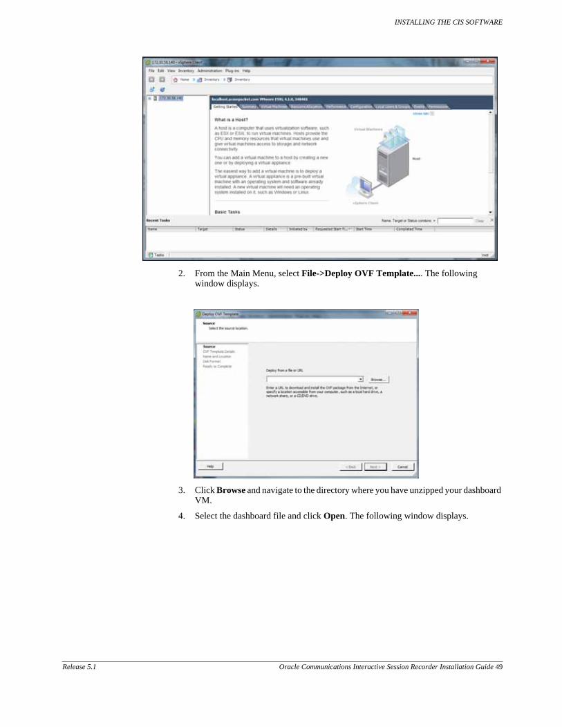
2. From the Main Menu, select File->Deploy OVF Template.... The following window displays.
3. Click Browse and navigate to the directory where you have unzipped your dashboard VM.
4. Select the dashboard file and click Open. The following window displays.

INSTALLING THE CIS SOFTWARE
50 Oracle Communications Interactive Session Recorder Installation Guide Release 5.1
5. Click Next in the Deploy OVF Template window. The Name and Location window displays. This field is automatically populated with the name and location of the virtual machine you selected in Step 4.
Note: You are able to change this name if desired.
6. Click Next. The Disk Format window displays.

INSTALLING THE CIS SOFTWARE
Release 5.1 Oracle Communications Interactive Session Recorder Installation Guide 51
7. Select Thin provisioned format and click Next. The Network Mapping window displays.
8. Map the Source Network column to the Destination Network column if only one physical interface is configured on your ESXi host.
9. Map VM Local to the network you crated in Configuring the Local Network.
10. Click Next. The following window displays.
11. Review all selections in the Ready to Complete window and click Finish.
12. Click OK to close the Deploy OVF Template window. The following window displays.

INSTALLING THE CIS SOFTWARE
52 Oracle Communications Interactive Session Recorder Installation Guide Release 5.1
13. In the left column, click on the Virtual Machine called dashboard.
14. Press the Start/Play icon to power ON the dashboardVM.
15. To complete the Dashboard VM installation, configure the network address of the Dashboard VM using the procedure in Configuring the VM Network Addresses.
When this step is complete, the Dashboard VM is installed and on the network.
Configuring the VM Network Addresses
Once you deploy a VM (Index, Dashboard, Monitor, Remote Archival Web Service), you must configure the network address of that virtual machine. Use the procedures in this section to configure the network address of each VM.
1. Open the vSphere Client application to the Home page.

INSTALLING THE CIS SOFTWARE
Release 5.1 Oracle Communications Interactive Session Recorder Installation Guide 53
2. Select a virtual machine in the left column for which you want to configure a network address, and then click on the Console tab.
3. Click in the main panel of this window. The following screen displays.
4. Press Enter.
Note: You must press Enter to refresh the screen after placing the cursor in the console window.
5. Your mouse is confined to the console panel. Press <Alt> + <Ctrl> to release it. The following screen displays with the applicable VM prompt.
6. Log in to the VM with the following and press Enter: <VM> Login: root Password: 64^5377
Note: The root and password logins are the same on both VMs.
The following screen displays.
7. Execute the configCis.sh script.
8. Select one of the following:
• s <Enter>—Show the current configuration
• q <Enter>—Quit the application
• m <Enter>—Modifies the current CIS configuration. The following fields appear:
• Enter host IP: [<current IP>]
– The Eth0 interface IPv4 address of the CIS host
• Enter prefix: [16]
– The routing prefix, e.g. 192.168.1.1/16
• Enter gateway IP: [<current_gateway_ip>]

INSTALLING THE CIS SOFTWARE
54 Oracle Communications Interactive Session Recorder Installation Guide Release 5.1
– The IPv4 address of the network gateway or router.
• Enter DNS1 IP: [<current_dns1_ip or none>]
– The IPv4 address of the first DNS, which may be skipped (set to none) and ignored
• Enter DNS2 IP: [<current_dns2_ip or none>]
– The IPv4 address of the second DNS, which may be skipped (set to none) and ignored
Note: To skip to the next field, hit <Enter>.
Configuring the network address of the VM is complete.
9. Repeat this process for each CIS host that requires installation or configuration.
Once you have accurately entered the proper fields, the message “Configuration updated” appears and the CIS hosts restarts.
Note: If there are any failures, you are alerted at this time.
Configure Automatic Start of the VMs
When all CIS components are installed, you must configure the virtual machines to start automatically.
Use the following procedure to configure the virtual machines to start automatically.
To configure the VMs to start automatically:
1. Open the vSphere Client application to the Home page.
2. Click on the Configuration tab.
3. In the left column, under the Software category, click on Virtual Machine Startup/Shutdown. The following screen displays.

INSTALLING THE CIS SOFTWARE
Release 5.1 Oracle Communications Interactive Session Recorder Installation Guide 55
4. In the upper right corner of the window, click Properties. The following window displays:
5. In System Settings section, enable the Allow virtual machines to start and stop automatically with the system by placing a check mark in the box.
6. In the Startup Order section, select the Index entry and then click <Move Up> to include the index virtual machine in the Automatic Startup group.
Note: When moving the entry up in the window, continue to click <Move Up> until the entry is in the appropriate category.
7. Select the Dashboard entry and then click <Move Up> to place the Dashboard VM just below the Index entry in the Automatic Startup group.
8. Click OK. The window should displays as follows.

INSTALLING THE CIS SOFTWARE
56 Oracle Communications Interactive Session Recorder Installation Guide Release 5.1
You must continue the ISR installation process by installing the Record and Store Server (RSS). For RSS installation procedures, see Installing the RSS Software.
Configuring the Timezone on a CIS Host
The timezone of each CIS host has a default setting of “America/New_York”, also known as the Eastern Time Zone. To change the timezone on the ISR, the administrator must set all hosts to the timezone of choice and the RSS hosts must be set to the same timezone as all CIS hosts (for RSS timezone configuration see the section Configuring the Timezone in Chapter 4, Installing the RSS Software).
To configure the timezone of the CIS host:
1. Connect to the CIS host with a vSphere console or SSH client.
2. Execute the rm -f /etc/localtime command to remove the previous timezone setting.
3. Execute the ln -s /usr/share/zoneinfo/<region>/<timezone> /etc/localtime command to link the updated timezone.
Note: When you enter the /usr/share/zoneinfo/<region> and /usr/share/zoneinfo/<region>/<timezone> commands the CLI provides options for both the <region> and <timezone> arguments.

Release 5.1 Oracle Communications Interactive Session Recorder Installation Guide 57
4 Installing the RSS Software
Introduction
This section provides information and procedures for installing the RSS software for the ISR.
What is RSS?
The RSS is a component of the ISR under the control of the CIS, that records sessions and manages the call recording storage and archival processes. It selects, starts, and stops recordings using Web services APIs.
In the ISR installation process, you install the RSS component after installing the CIS component.
Note: If you are going to install a 300GB CIS and/or RSS server, use the procedure in Appendix C, Installing RAID on the CIS and RSS Servers, to install RAID before attempting the CIS and RSS installation process.
Installing RSS
Use the procedures in this section to perform the following:
– Load RSS software
– Configure RSS Networking
Loading RSS Software
Use this procedure to load the software to your RSS server.
To load the software:
1. Insert USB flash drive containing the ISR installer package into the USB port on your RSS server.
2. Reboot the server.
3. During the BIOS load, select the option “Boot from the USB”.
Note: On an HP DL-360 system, press <F11>, and select Option 3. On some HP DL-360 systems, you may be required to press <F1> during the boot process, depending on the BIOS settings of the individual machines.
The RSS software proceeds to install. The RSS server reboots automatically.
Note: There is no interaction with the user during the install. The install deletes all data on the drive without prompting.

INSTALLING THE RSS SOFTWARE
58 Oracle Communications Interactive Session Recorder Installation Guide Release 5.1
Warning: DO NOT REMOVE THE USB THUMB. Proceed to Configuring RSS Networking to continue the installation and configuration.
Configuring the Serial Console Settings
In order to change the serial console settings for the RSS, you must execute the set-chassis-console command to direct the console output to the appropriate serial or VGA port. Also, you can change the console settings within the CLI console object.
To choose the console settings on an RSS, you must use the set-chassis-config-console command from the NN-ISR> prompt.
NN-ISR>set-chassis-config-console serial-1
NN-ISR>set-chassis-config-console ?
Set management output for future reboots
syntax: set-chassis-config-console console
serial-0 Serial port 0 console
serial-1 Serial port 1 console
vga VGA console
NN-ISR>
Confirm that you have the management console setting correct using the show chassis-config command.
NN-ISR>show chassis-config
boot-partition: system-1
system-partitions: 2
management-console: serial-1
ipmi-admin: enabled
You must reboot the server for changes in the console output to be applied. Before performing the reboot, you may want to verify if the console is configured correctly for your terminal client.
NN-ISR>config box console
config console>set rate 115200
config console>set data-bits 8
config console>set parity none
config console>set stop-bits 1
config console>set flow-control none
NN-ISR>exit
Do you want to commit your changes before you exit (y or n)? y
Do you want to update the startup configuration (y or n)? y
NN-ISR>

INSTALLING THE RSS SOFTWARE
Release 5.1 Oracle Communications Interactive Session Recorder Installation Guide 59
Configuring RSS Networking
For RSS to operate properly, you must configure the RSS using the procedures in this section.
Before You Begin The installation of the RSS requires you to access and use specific files/directory locations on your RSS server.
File/Directory Description
/etc/hosts Host information for RSS
/cxc/isrl.elf RSS binary executable file
/cxc/vmgConfig.xml RSS configuration file
Note: See Appendix F, vmgConfig.xml Parameters for parameter descriptions.
/cxc/vmgLog.properties RSS log file
/cxc/CDRLog.properties Call Detail Record (CDR) log file
/cxc/converterl.elf Media Converter (RMC) executable file
/cxc/converterLog.properties Media Converter (RMC) log file
/cxc/converterConfig.xml Media Converter (RMC) configuration file
/var/run/isr.pid RSS process ID file used by the monitor/manager to identify ISR processes and their states
/cxc_common/ISR/ISRLogs/ISR.log ISR log file
/cxc_common/ISR/ISRLogs/ISRService.log ISR Service Start/Stop service log file
/cxc_common/ISR/Recordings Base of ISR recordings storage
/cxc_common/ISR/CDR Base of ISR CDR log storage
/usr/local/jboss-7.1.1/server/default/log/server.log JBOSS Application Server Log file
/cxc_common/ISR/ApiLog/IsrApi.log RSS REST: VXML API log file
/cxc_common/ISR/Archiver/ArchivalService.log ISR Archiver Service log file
/cxc/configRss.sh RSS configuration script

INSTALLING THE RSS SOFTWARE
60 Oracle Communications Interactive Session Recorder Installation Guide Release 5.1
Configure Primary Network Interface
To configure primary network interface:
1. After installing the ISR, your system reboots and performs an RSA key generation.
Note: It is safe to ignore the messsage “Unable to determine the product from Unknown”.
2. When booting is complete (after RSA key generation), press <Enter> to display the login prompt.
3. At the Login as prompt, enter root and press <Enter>. Login as: root The password prompt displays.
4. At the Password prompt, enter sips and press <Enter>. root@<hostname>’s password> sips The following prompt and message display. Net-Net ISR Copyright (c) 2004-2012 Acme Packet Inc. Username:
5. No username is required so press <Enter>. Username: (leave blank) The password prompt displays.
6. No password is required so press <Enter>. Password: (leave blank) The following message displays followed by the ISR hostname prompt. “Access granted since there are no configured users.” NN-ISR>
7. Enter show ethernet and press <Enter> to list the available Ethernet devices. NN-ISR> show ethernet If an empty device list displays, you must re-install the network interface controller (NIC) software. Perform Step 6 and 7. If the list contains ethernet devices, skip Step 8 and 9 and go to Step 10.
8. Enter install nic and press <Enter>. NN-ISR> install nic

INSTALLING THE RSS SOFTWARE
Release 5.1 Oracle Communications Interactive Session Recorder Installation Guide 61
9. Enter show ethernet and press <Enter> to list the available Ethernet devices. NN-ISR> show ethernet A list of Ethernet devices available on the ISR display.
10. Enter config setup and press <Enter>. NN-ISR> config setup The Set box\hostname” prompt displays.
11. Enter the hostname of your RSS and press <Enter>. For example, “RSS01”. Set box\hostname: RSS01
The “Config box\interface” prompt displays.
Note: Configure the ethernet adapter as the same one displayed when the show ethernet command was executed. This is usually eth0.
12. Enter eth0 as the Ethernet port you want to configure and press <Enter>. Config box\interface: eth0
The “Set box\interface eth0\ip a\ip-address” prompt displays.
13. Enter the IP address of the ISR followed by the local-link designation and press <Enter>. For example, 172.45.3.4/16. Set box\interface eth0\ip a\ip-address: 172.45.3.4/16
Note: You must supply the local-link designation with the IP address (i.e., /16). Other local-link designation formats from RFC 5735 are supported, if required.
The “Set box\interface eth0\ip a\ ssh” prompt displays.
14. Enter Y to allow Secure Shell access to the ISR and press <Enter>. Set box\interface eth0\ip a\ssh [y|n]: y
The “Set box\interface eth0\ip a\ web” prompt displays.
15. Enter Y to allow Web access to the ISR and press <Enter>. Set box\interface eth0\ip a\web [y|n]: y
The “Set box\interface eth0\ip a\ routing\route” prompt displays.
16. Specify admin or any other LAN designation and press <Enter>. Set box\interface eth0\ip a\routing\route: admin

INSTALLING THE RSS SOFTWARE
62 Oracle Communications Interactive Session Recorder Installation Guide Release 5.1
Note: The name specified here has no impact on functionality. It is a descriptor only.
The “Set box\interface eth0\ip a\ gateway” prompt displays.
17. Enter the IP address for the network default gateway and press <Enter>. For example, 172.45.0.1. Set box\interface eth0\ip a\gateway: 172.45.0.1
The “Set box\cli\ prompt” prompt displays.
18. Enter the command line interface (CLI) prompt that you want to display when using the CLI (or enter the hostname) , and press <Enter>. For example, RSS01. Set box\cli\prompt: RSS01
The “Commit these changes” prompt displays.
19. Enter Y and press <Enter>. Commit these changes [y|n]: y
The “Update the config and continue” prompt displays.
20. Enter Y and press <Enter>. Update the config and continue [y|n]: y
The “NN-ISR>” prompt displays.
21. Remove the USB flash drive from the USB port on your RSS server.
Note: This USB flash drive can now be used as a backup rescue drive for the RSS. The network configuration you just performed is saved to your RSS server as well as to the flash drive.
22. After the ISR has restarted, at the “login as” prompt, enter root and press <Enter>. login as: root The password prompt displays.
23. At the “Password” prompt, enter “sips” and press <Enter>. root@<hostname>’s password> sips The following prompt and message display. Net-Net OS-E Copyright (c) 2004-2012 Acme Packet Inc. Username:
24. No username is required so press <Enter>. Username: (leave blank) The password prompt displays.
25. No password is required so press <Enter>. Password: (leave blank) The following message displays followed by the ISR hostname prompt. “Access granted since there are no configured users.” NN-ISR>
Configure a Media network interface card (NIC) for the RSS server using the procedures in Configuring Media NIC.

INSTALLING THE RSS SOFTWARE
Release 5.1 Oracle Communications Interactive Session Recorder Installation Guide 63
Configuring Media NIC After configuring the primary network interface on the RSS server, proceed with the following steps to configure your media network interface card (NIC).
To configure the media NIC:
After configuring the primary network interface on the RSS server, the ISR prompt displays.
1. Enter config box and press <Enter>. NN-ISR> config box
The “Config box” prompt displays.
2. Enter config interface eth1 to configure the Ethernet 1 port on the ISR, and press <Enter>. Config box> config interface eth1
The “Config interface eth1” prompt displays.
3. Enter config ip media to configure the Media NIC on the ISR, and press <Enter>. Config interface eth1> config ip media
The “Config ip media” prompt displays.
4. Enter set ip-address static <<IP address>/<link designation>> to set the static IP address and link designation on the ISR, and press <Enter>. Config ip media> set ip-address static <10.10.248.15/24>
The “Config ip media” prompt displays.
5. Enter show to show the current configuration of Ethernet 1 on the ISR, and press <Enter>. Config ip media> show
The following displays to the screen: Box
Interface eth1 Ip media
…
Admin enabled Ip-address static <10.10.248.15>/24 …
Config ip media>
6. Enter exit and press <Enter>. Config ip media> exit A prompt displays asking if you want to commit your changes.
7. Enter Y and press <Enter>. Do you want to commit your changes before you exit [y|n]> y A prompt displays asking if you want to update the startup configuration.
8. Enter Y and press <Enter>. Do you want to update the startup configuration [y|n]> y The “NN-ISR>” prompt displays.
Finalize ISR Configuration
After configuring the media NIC on the RSS server, proceed with the following steps to finalize your ISR configuration.
To finalize the ISR configuration:
After configuring the media NIC on the RSS server, the ISR prompt displays.

INSTALLING THE RSS SOFTWARE
64 Oracle Communications Interactive Session Recorder Installation Guide Release 5.1
1. Enter show processes to verify the ISR is up and running. NN-ISR> show processes The show processes command displays statistics for all active processes. The following is an example of this command’s output.
process id condition run-level starts uptime fds
------- -- --------- --------- ------ ------ ---
monitor 6217 running 7 1 0 days 19:01:06 17
manager 6410 running 7 1 0 days 19:01:06 39
web 6678 running 7 3 0 days 18:55:39 156
WS 0 idle init 0 0 days 00:00:00 0
SSH 6676 running none 2 0 days 18:55:39 4
ISR 6443 running none 5 0 days 18:55:41 12
RMC 4721 running none 1 4 days 23:26:08 5
The following table identifies each column in this display.
Column Description
Process Current active process on the ISR.
ID Temporary ID assigned to the current process.
Note: The process ID changes each time you initiate the “restart process isr” command.
Condition Current status of the process.
Run-Level State of the process after reboot. ISR should be set to “none” because it is managed by manager process above.
Starts Number of times the process has started since the server was booted. Uptime changes on every restart.
Uptime Current amount of time that the process has been up and running.
Note: The “Uptime” is a timer so the “0” indicates the process has restarted. Any number higher than zero (0) indicates how long the process has been up and running since the last restart.
FDS File descriptors
2. Next, execute the configRss.sh script using the procedures in Configuring configRss.sh File.
Running configRss.sh Script
3. Enter /cxc/configRss.sh and hit <Enter>.
4. Select one of the following:
• s <Enter>—Show the current configuration
• q <Enter>—Quit the application
• m <Enter>—Modifies the current RSS configuration. The following fields appear:
• Enter Database IP: [169.254.1.50]
– The IPv4 address to connect to the Index host
• Enter RSS SIP IP: [<current_IP>]
– The IP v4 address used by the RSS to listen to SIP messages

INSTALLING THE RSS SOFTWARE
Release 5.1 Oracle Communications Interactive Session Recorder Installation Guide 65
• Enter Number of Channels: [500]
– The configured number of concurrent sessions to configure for this RSS host. The total concurrent sessions of the RSS hosts must comply with the customer’s contract with Oracle.
Note: To skip to the next field, hit <Enter>.
5. Enter restart process isr and press <Enter>.
Note: Restarting the ISR Process affects all sessions in progress and should only be done when you have confirmed no active sessions are being managed or recorded on the system.
6. Next, configure the timezone on the RSS to be the same as the timezone on the CIS using the procedures in Configuring the Timezone.
Note: You can adjust the ArchiverCron Schedule by editing the IPCRArchiver.sar file. For more information, see Appendix D, CIS FAQs and Additional Information.
Configuring the Timezone
After finalizing the ISR configuration, you must configure the timezone on the RSS to be the same as the timezone on the CIS. Use the following procedure to configure the timezone.
To configure the timezone:
1. At the NN-ISR> prompt, enter config box and press <Enter>. NN-ISR> config box The “config box” prompt displays.
2. Enter set timezone ? and press <Enter>. config box> set timezone ? Adding the ? at the end of the command, displays a list of timezone locations for you to review.
Timezone ACLI Value
Alaska Alaska
Aleution Aleution
Arizona Arizona
Central Central
Indiana Indiana
Eastern Eastern
Hawaii Hawaii
Starke Starke
Michigan Michigan
Mountain Mountain
Pacific Pacific
Samoa Samoa
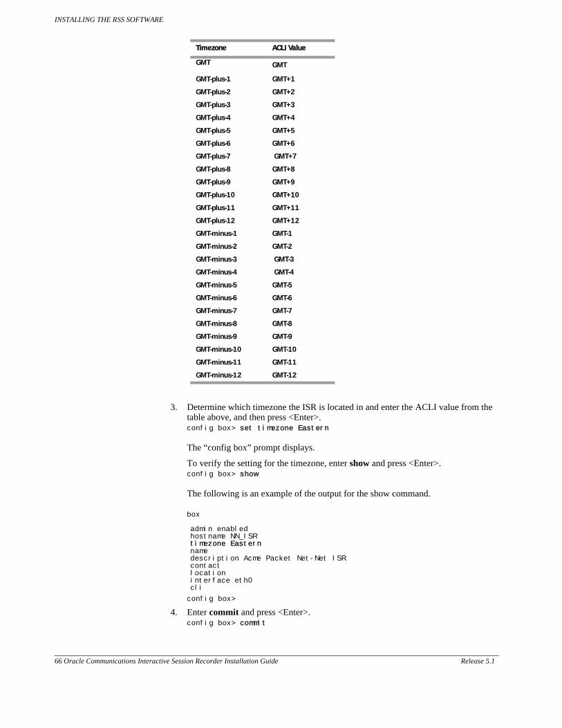
INSTALLING THE RSS SOFTWARE
66 Oracle Communications Interactive Session Recorder Installation Guide Release 5.1
3. Determine which timezone the ISR is located in and enter the ACLI value from the table above, and then press <Enter>. config box> set timezone Eastern The “config box” prompt displays.
To verify the setting for the timezone, enter show and press <Enter>. config box> show The following is an example of the output for the show command. box
admin enabled hostname NN_ISR timezone Eastern name description Acme Packet Net-Net ISR contact location interface eth0 cli
config box>
4. Enter commit and press <Enter>. config box> commit
GMT GMT
GMT-plus-1 GMT+1
GMT-plus-2 GMT+2
GMT-plus-3 GMT+3
GMT-plus-4 GMT+4
GMT-plus-5 GMT+5
GMT-plus-6 GMT+6
GMT-plus-7 GMT+7
GMT-plus-8 GMT+8
GMT-plus-9 GMT+9
GMT-plus-10 GMT+10
GMT-plus-11 GMT+11
GMT-plus-12 GMT+12
GMT-minus-1 GMT-1
GMT-minus-2 GMT-2
GMT-minus-3 GMT-3
GMT-minus-4 GMT-4
GMT-minus-5 GMT-5
GMT-minus-6 GMT-6
GMT-minus-7 GMT-7
GMT-minus-8 GMT-8
GMT-minus-9 GMT-9
GMT-minus-10 GMT-10
GMT-minus-11 GMT-11
GMT-minus-12 GMT-12
Timezone ACLI Value

INSTALLING THE RSS SOFTWARE
Release 5.1 Oracle Communications Interactive Session Recorder Installation Guide 67
The “config ” prompt displays.
5. Enter exit and press <Enter>. config> exit The “Do you want to update the startup configuration?” prompt displays.
6. Enter Y and press <Enter>. Do you want to update the startup configuration (y or n)? y NN-ISR> The “NN-ISR>” prompt displays.
The timezone is now configured.
Configure the Network Time Protocol (NTP) services for the RSS server using the procedures in Configuring NTP Services.
Configuring NTP Services
After configuring the timezone, you must configure the NTP services. Use the following procedure to configure the NTP services.
To configure the NTP services:
1. At the NN-ISR> prompt, enter config box and press <Enter>. NN-ISR> config box ntp-client The “config box” prompt displays.
2. Enter set server <NTP server IP address>, which is your NTP server, and press <Enter>. config ntp-client> set server 150.214.94.5
The “config ntp-client” prompt displays.
To add multiple NTP servers, run set server for each server you are adding.
3. Enter show to verify that the server was set to the correct IP address, and press <Enter>. config ntp-client> show
The following is an example of the show command output.
box
ntp-client
admin enabled
server[1] 150.214.94.5
poll-interval 10 minutes
4. Enter commit to save the NTP configuration, and press <Enter>. config ntp-client> commit
The “config” prompt displays.
5. Enter exit to exit the configuration container, and press <Enter>. config> exit
The following prompt displays: Do you want to update the startup configuration (y or n)?
6. Enter y to update the startup configuration with the NTP services you specified, and press <Enter>. Do you want to update the startup configuration (y or n)? y
The “NN-ISR>” prompt displays. The installation of the RSS is complete.

INSTALLING THE RSS SOFTWARE
68 Oracle Communications Interactive Session Recorder Installation Guide Release 5.1
Applying RSS License
This section provides the information and procedures for applying an RSS license.
The RSS is licensed for two sessions by default. For additional capacity, you must acquire and apply a license file. This file is generated by Oracle and provided, via email, when the order is filled. If you do not have your license file or you have questions on the session capacity, please contact your Oracle sales representative or installation engineer.
The license file must be named VoIPMediaGateway.lic, and the name IS case sensitive. If you are licensing multiple RSS servers, the license files may be named with the server MAC address when provided. You must rename these license files to VoIPMediaGateway.lic for the files to correctly apply to the RSS.
To apply the RSS license:
This procedure assumes the use of the Open Source Secure FTP (SFTP) Client application called FileZilla, but you can use any FTP client that supports SFTP.
1. Open an FTP client.
2. In the Host field, enter the RSS management IP address. For example, Host: 172.30.58.16
3. In the Port field, enter 22. For example, Port: 22
4. In the Username and Password fields, enter root and sips, respectively. For example, Username: root Password: sips
The license file is stored in the /cxc directory of the RSS. When you connect via FTP (or SSH) you are in the /cxc directory.
5. Copy the license file from your local machine to the RSS using the FTP application.
6. Using an SSH Client, login to the ISR by entering root at the “Login as” prompt, and press <Enter>. Login as: root The password prompt displays.
7. At the “Password” prompt, enter sips and press <Enter>. root@<hostname>’s password> sips The following prompt and message display. Net-Net OS-E Copyright (c) 2004-2012 Acme Packet Inc. Username:
8. No username is required so press <Enter>. Username: (leave blank) The password prompt displays.
9. No password is required so press <Enter>. Password: (leave blank) The following message displays followed by the ISR hostname prompt. “Access granted since there are no configured users.” NN-ISR>

INSTALLING THE RSS SOFTWARE
Release 5.1 Oracle Communications Interactive Session Recorder Installation Guide 69
10. At the “<Hostname>#”prompt, enter restart process isr and press <Enter>. <NN-ISR> # restart process isr
Note: The “restart process isr” restarts the ISR and allows the RSS to read the new license information immediately.
Warning: The “restart process isr” command terminates all calls in progress and should not be used on a production system with live calls.
Verify RSS License Applied
You can use either of two methods to verify that the RSS license was applied to the ISR:
• Viewing through the ISR Dashboard (at the path Admin->Manage Sites-><edit a Site>).
• Viewing in the ISR log file (at the path /cxc_common/ISR/ISRLogs/ISR.log)
Using the ISR Log File
To verify the RSS license is applied:
1. While still logged in after applying the license, enter shell from the prompt to get into the Linux shell.
2. Enter cd /cxc_common/ISR/ISRLogs and press <Enter>. The “cxc_common/ISR/ISRLogs” prompt displays.
Enter “cat ISR.log” and press <Enter>. /cxc_common/ISR/ISRLogs> cat ISR.log The following is an example of the ISR.log contents. 12/14/2011 23:21:32[NOTICE] mixMaster: Starting 50 Media Channels... 12/14/2011 23:21:32[ INFO] mixMaster: Initializing Channel 1/50 The “Starting 50 Media Channels” in the above example indicates there are 50 sessions licensed on the RSS. If the number of sessions is correct, this indicates the RSS license was installed successfully.
Proceed to Post-Install Verification and Configuration to verify connectivity between the CIS and RSS and all components, and to make your first call.

INSTALLING THE RSS SOFTWARE
70 Oracle Communications Interactive Session Recorder Installation Guide Release 5.1
Applying Converter License
The ISR platform handles sessions containing G.729 media and the recording and playback of these sessions using a media converter (RMC). This RMC is automatically installed when performing the CIS/RSS installations. However, in order for you to use RMC on the ISR, you must purchase the RMC license. Contact your Oracle sales representative for more information about obtaining the RMC license.
The ISR RMC is a converter that converts incoming G.729 recordings from Real-Time Transport Protocol (RTP) packet data (“.rpdd” formatted files) to Pulse Code Modulation (PCM) wave files (“.wav” formatted files), for playback by the ISR Dashboard. It allows the ISR to accept calls from a G.729 codec. In order for you to use RMC on the ISR, you must purchase the RMC license. Contact your Oracle sales representative for more information about obtaining the RMC license. For more information about the RMC converter, see Appendix E, ISR RMC.
This section provides information for applying the RMC converter license to the ISR.
To apply the converter license:
Note: This procedure assumes you have just configured the converterConfig.xml file and the NN-ISR> prompt displays.
1. At the ISR prompt, enter a shell session by entering “shell” and press <Enter>. NN-ISR> shell The hostname prompt displays. <hostname> #
2. Enter “ifconfig”, and press <Enter>. <hostname> # ifconfig The following is an example of the “ifconfig” output:
eth0 Link encap:Ethernet HWaddr 3C:4A:92:F5:9B:C4
inet
addr:172.30.58.141 Bcast:172.30.255.255 Mask:255.255.0.0
UP BROADCAST RUNNING MULTICAST MTU:1500 Metric:1
RX packets:184074 errors:0 dropped:0 overruns:0 frame:0
TX packets:34402 errors:0 dropped:0 overruns:0 carrier:0
collisions:0 txqueuelen:1000
RX bytes:20765532 (19.8 Mb) TX bytes:3099950 (2.9 Mb)
Interrupt:30 Memory:f4000000-f4012800
3. Make a note of the “HWaddr” in the “ifconfig” command output. This is the MAC address of the ISR.
4. Contact your Oracle sales representative to acquire an RMC converter license. You must provide the following information when requesting a license:
• System name
• Number of ports
• Production or Development license
• License expiration (Development licenses only)
• Product name (converter with G.729 for standard ISR RSS hosts)
After receiving the license key, transfer the key to the RSS host’s filesystem using either of the following methods:

INSTALLING THE RSS SOFTWARE
Release 5.1 Oracle Communications Interactive Session Recorder Installation Guide 71
Using a UNIX Shell Session
1. At the hostname prompt in a shell session, enter the following and press <Enter>: <hostname> # scp converter.lic root@<hostname>:/cxc/ The password prompt displays.
2. Enter your password and press <Enter>. Password # ********* The license key file proceeds to copy to the RSS host’s filesystem.
3. Enter “restart process rmc” and press <Enter>. <hostname> # restart process rmc
Note: The “restart process rmc” restarts the RMC converter and allows the RSS to read the converter license information immediately.
Warning: The “restart process rmc” command terminates all conversions currently in progress.
4. Verify that the converter license file was installed by viewing the ISR log files.
Using a USB Flash Drive
1. Copy the license key to the USB flash drive.
2. Insert the USB flash drive into a USB port on the RSS host system.
3. Go to your shell session you opened in Steps 1-6.
4. Locate the USB flash drive on your system by entering the following and press <Enter>: <hostname> # dmesg | tail -15 The following displays: Device scan complete. Sda: sda1 sda2 Sda1 should be the applicable USB device (first device scanned by your system and found).
5. Mount the USB device to the local filesystem by entering the following (assumes sda1 is the USB device), and press <Enter>: <hostname> # mount -t vfat /dev/sda1 /mnt/usb
6. Enter the following and press <Enter>: <hostname> # ls /mnt/usb This displays a list that shows the “converter.lic” file.
7. Copy the license file to the RSS host’s filesystem: <hostname> # cp /mnt/usb/converter.lic /cxc/
8. Enter “restart process rmc” and press <Enter>. <hostname> # restart process rmc
Note: The “restart process rmc” restarts the RMC converter and allows the RSS to read the converter license information immediately.

INSTALLING THE RSS SOFTWARE
72 Oracle Communications Interactive Session Recorder Installation Guide Release 5.1
Warning: The “restart process rmc” command terminates all conversions currently in progress.
9. Verify that the converter license file was installed by viewing the ISR log files.
10. If you copied the converter license file using the USB flash drive, unmount/eject the drive by entering the following, and press <Enter>: <hostname> # unmount /mnt/usb Physically remove the USB flash drive from the USB port on your system.

Release 5.1 Oracle Communications Interactive Session Recorder Installation Guide 73
5 Post-Install Verification and Configuration
Introduction
This section provides information and procedures for post-install verification and configuration. It includes verifying connectivity between the CIS and RSS and testing the call recording functionality of the ISR. It also includes required ISR configuration that must be performed before making the first call.
Verifying Connectivity Between the RSS and the Index VM
When installation of the RSS and Index VM are complete, you can test the connectivity between these components to verify they are working properly. Procedures in this section include:
• Testing connectivity between the RSS and Index VM
• Logging into the dashboard
Testing Connectivity
Use the following procedure to test connectivity between the RSS and Index VM.
To test connectivity:
1. After rebooting the ISR, press <Enter> to display the login prompt.
2. At the “Login as” prompt, enter “root” and press <Enter>. Login as: root The password prompt displays.
3. At the “Password” prompt, enter “sips” and press <Enter>. root@<hostname>’s password> sips The following prompt and message display. Net-Net OS-E Copyright (c) 2004-2012 Acme Packet Inc. Username:
4. No username is required so press <Enter>. Username: (leave blank) The password prompt displays.
5. No password is required so press <Enter>. Password: (leave blank) The following message displays followed by the ISR hostname prompt. “Access granted since there are no configured users.” NN-ISR>
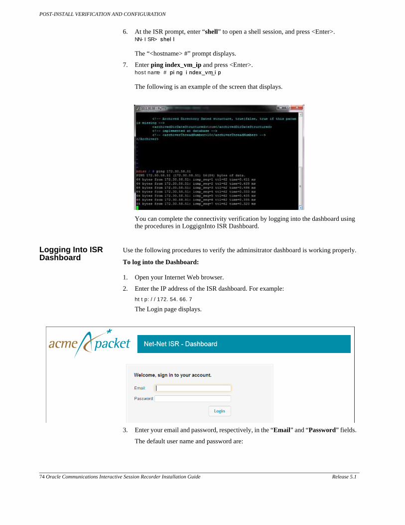
POST-INSTALL VERIFICATION AND CONFIGURATION
74 Oracle Communications Interactive Session Recorder Installation Guide Release 5.1
6. At the ISR prompt, enter “shell” to open a shell session, and press <Enter>. NN-ISR> shell The “<hostname> #” prompt displays.
7. Enter ping index_vm_ip and press <Enter>. hostname # ping index_vm_ip The following is an example of the screen that displays.
You can complete the connectivity verification by logging into the dashboard using the procedures in LoggignInto ISR Dashboard.
Logging Into ISR Dashboard
Use the following procedures to verify the adminsitrator dashboard is working properly.
To log into the Dashboard:
1. Open your Internet Web browser.
2. Enter the IP address of the ISR dashboard. For example:
http://172.54.66.7
The Login page displays.
3. Enter your email and password, respectively, in the “Email” and “Password” fields.
The default user name and password are:

POST-INSTALL VERIFICATION AND CONFIGURATION
Release 5.1 Oracle Communications Interactive Session Recorder Installation Guide 75
User name: [email protected] Password: admin123 Note: You are required to change the default password, admin123, upon initial login and then again every 90 days.
4. Respond to the prompts as applicable to change your password. After changing your password, the following page displays.
Navigation Icons The ISR Dashboard provides specific navigation tools you can use to perform functions when required. The following table identifies these tools.
Icon Description
Add - Adds an item to the list (for example, +Add New).
Delete - Removes the item from the list.
Details - Shows additional information about the item.
Back - Navigates to the previous screen.
Forward - Navigates to the next screen.
Play - Plays the specific “.wav” file recording stored in the ISR database.
Download - Downloads the selected recording to your PC or local server.
User Audit Trail - Display the selected user’s audit trail (Action performed, time, IP address, etc.)
RSS Details - Displays and allows you to edit RSS details and advanced configuration information about a Site.
Enabled - Status that indicates the element is enabled or active.

POST-INSTALL VERIFICATION AND CONFIGURATION
76 Oracle Communications Interactive Session Recorder Installation Guide Release 5.1
For more information about using the features and functions of the ISR dashboard, see the Interactive Session Recorder Administrator Guide or the Interactive Session Recorder User Guide.
Before you can make the first call, you must configure the RSS and the route to use to receive the call. Use the procedures in Configuring the ISR for Recording a Call to configure the RSS and route.
Configuring the ISR for Recording a Call
You can place a call to verify that the ISR call recording functionality is working properly. Before you can place a call, you must configure the following on the ISR:
• Add a new site for the RSS server
• Add a new RSS to the site
• Add a Session Agent (phone or device to receive the call from the ISR)
• Add a Route
Add Site for RSS Server
To verify that the RSS and the dashboard are communicating, you must add a new site for the RSS server. Use the following procedure to add a new site.
To add a site:
1. From the Main Menu, click Admin. The following page displays.
Disabled - Status that indicates the element is disabled or inactive.
Error - Status that indicates an error occurred on the element.
Session Agent Events - Displays the events associated with a Session Agent.
Help - Displays information about online Technical Support.
Logoff - Exits from the ISR Dashboard.
Icon Description

POST-INSTALL VERIFICATION AND CONFIGURATION
Release 5.1 Oracle Communications Interactive Session Recorder Installation Guide 77
2. Click Manage Sites. The following page displays.
3. Click New Site. The following dialog box displays.
4. In the Name field, enter a name for the Site and click Create. Valid values are alpha-numeric characters. The new site displays on the Sites page.

POST-INSTALL VERIFICATION AND CONFIGURATION
78 Oracle Communications Interactive Session Recorder Installation Guide Release 5.1
For additional information about Sites, see the Interactive Session Recorder Administrator Guide.
Note: Each RSS should be contained in its own site, regardless of physical location.
Add the RSS to a Site
To enable connectivity between the RSS and the CIS, you must add the new RSS to a site. Use the following procedure to add the new RSS.
To add the new RSS to the site:
1. On the “All Sites” page, select a site for which you want to add the RSS, and click .
The following page displays.

POST-INSTALL VERIFICATION AND CONFIGURATION
Release 5.1 Oracle Communications Interactive Session Recorder Installation Guide 79
The RSS block displays the following:
Field Description
RunningDisplays the number of RSSs currently enabled (active.)
Running with errorsDisplays the number of RSSs currently active with errors.
Not running (or could not connect to)
Displays the number of RSSs currently disabled (inactive).
Total ports in use Displays the total number of RSS ports currently in use.
Total ports Displays the total number of licensed ports.
2. Click the RSS block. The following page displays.

POST-INSTALL VERIFICATION AND CONFIGURATION
80 Oracle Communications Interactive Session Recorder Installation Guide Release 5.1
The RSS page displays the following about each RSS.
Column Description
Name Name of the RSS.
IP Address IP Address of the RSS in dotted decimal format.
XMLRPC Port Port number of the XML-RPC service. This service accepts and queues remote call and recording commands.
Status Current status of the RSS . Status can be:
- Enabled (active)
Disabled (inactive)
Active with errors
Uptime Time elapsed since the last RSS process restart.
Ports being used Total number of ports currently being used on the RSS.
Total Ports Total number of licensed ports on the RSS.

POST-INSTALL VERIFICATION AND CONFIGURATION
Release 5.1 Oracle Communications Interactive Session Recorder Installation Guide 81
3. Click New RSS. The following dialog box displays.
4. In the Name field, enter a name for the RSS you are adding. Valid values are alpha-numeric characters.
5. In the IP Address field, enter the IP address (in dotted decimal format) on which the RSS is listening for SIP traffic.
6. In the XMLRPC Port field, enter the Port number of the XMLRPC service. This service accepts and queues remote call and recording commands. Default is 8888.
Note: This value should not be changed unless directed by Oracle Technical Support. Contact Technical Support for more information.
7. Click Create to add the RSS. The RSS window displays with the RSS assigned to the site.
For additional information about RSS, see the Interactive Session Recorder Administrator Guide.

POST-INSTALL VERIFICATION AND CONFIGURATION
82 Oracle Communications Interactive Session Recorder Installation Guide Release 5.1
Add a Session Agent
The Session Agent is the ISR's next-hop IP on all Pass-Thru Routes. The ISR delivers calls to the Session Agent after recording is started. The Session Agent can be an Session Border Controller (SBC), SIP PBX, or other SIP compatible device.
To test call recording in Pass-thru Mode, you must add a Session Agent. Use the following procedure to add a Session Agent.
Note: If you intend to use SIPREC or Conference Mode Recording, configuring a Session Agent is not required.
To add a Session Agent:
1. From the Main Menu, click Admin. The following page displays.
2. Click Manage Sites. The following page displays.

POST-INSTALL VERIFICATION AND CONFIGURATION
Release 5.1 Oracle Communications Interactive Session Recorder Installation Guide 83
Select a site for which you want to add the Session Agent, and click . The following page displays.
The Session Agents block displays the following:
Field Description
EnabledDisplays the number of Session Agents currently enabled (active).
FailedDisplays the number of Session Agents that are currently in the failed state.
Disabled Displays the number of Session Agenets currently disabled (inactive).
Max Failure Count Number of attempts the RSS makes to connect a call to a Session Agent(or pool of session agents) before the call is rejected. Valid values are 0 through 100. Default is 5
Max Failure Seconds Total number, in seconds, for which the Session Agent waits for a response before it considers the attempt unsuccessful and moves onto the next Session Agent. Valid values are 0 through 86400 seconds (24 hours). Default is 30 seconds.
Seconds Before Retry Number of seconds a Session Agent is taken out of service in the event of a failure. Valid values are 0 through 86400 seconds (24 hours). Default is 300 seconds (5 minutes).
Note: If you have only one Session Agent configured, set this value to 0 to prevent your Session Agent from being taken out of service.

POST-INSTALL VERIFICATION AND CONFIGURATION
84 Oracle Communications Interactive Session Recorder Installation Guide Release 5.1
3. Click the Session Agent block. The following page displays.
The Session Agent page displays the following about each Session Agent.
Column Description
Name Name of the Session Agent.
IP Address IP Address of the Session Agent in dotted decimal format.
Type Specifies whether the Session Agent is acting as a Primary orSecondary (failover) device.
Status Current status of the Session Agent. Status can be:
- Enabled (active)
Disabled (inactive)
Active with errors
Last Event Specifies the last event that occurred on the Session Agent.
4. Click New Session Agent. The following dialog box displays.
5. In the Name field, enter a name for the Session Agent you are adding. Valid values are alpha-numeric characters. For example, SA1.

POST-INSTALL VERIFICATION AND CONFIGURATION
Release 5.1 Oracle Communications Interactive Session Recorder Installation Guide 85
Note: This is the name associated with the receiving phone or device you are going to use to test a call.
6. In the IP Address field, enter the IP address (in dotted decimal format), for the Session Agent you are adding. For example, 2.2.2.2.
Note: This is the IP address associated with the receiving phone or device you are going to use to test a call.
7. In the Type field, select Primary as the Session Agent type for the Session Agent you are adding.
8. Click Create. The following page displays.
For additional information about Session Agents, see the Interactive Session Recorder Administrator Guide.
Before making your first call, you must configure a Route on the ISR for the calls to use. To set up a route, see Chapter 6, Configuring a Route (Conference Mode Recording).

POST-INSTALL VERIFICATION AND CONFIGURATION
86 Oracle Communications Interactive Session Recorder Installation Guide Release 5.1

Release 5.1 Oracle Communications Interactive Session Recorder Installation Guide 87
6 Setting up a Test Call
Introduction
This chapter provides information and procedures for configuring the first route to use for placing a test call to the ISR. It also includes information for setting up a Softphone for making the first call procedures for verifying that the recording was made and that the Dashboard works properly.
Configuring a Route (Conference Mode Recording)
Route configuration is important to the flexibility of your ISR installation. A route defines the parameters to evaluate and invoke recording, as well as the recording rules to apply for all calls received by the ISR. Users are given access to recordings based on routes.
Use the following test procedure to make your first recording. This procedure uses a wildcard route that applies the same recording rules to every call received. Please note that this is not the recommended configuration to deploy in a production system, as it eliminates the ability to assign users access to specific recordings.
Note: Use the new Route you configure in this section for call verification purposes only.
To configure a route:
1. Open your Internet Web browser.
2. Enter the IP address of the ISR. For example:
http://172.54.66.7
The Login page displays.
3. Enter your email and password, respectively, in the “Email” and “Password” fields.
The default user name and password are:
User name: [email protected] Password: admin123

SETTING UP A TEST CALL
88 Oracle Communications Interactive Session Recorder Installation Guide Release 5.1
Note: You are required to change the default password, admin123, upon initial login and then again every 90 days.
The following page displays.
4. From the Main Menu, click Admin. The following page displays.

SETTING UP A TEST CALL
Release 5.1 Oracle Communications Interactive Session Recorder Installation Guide 89
5. Click the Manage Routes . The following page displays.
The Route page displays the following about each Route.
Column Description
Account Name of the Account assigned to the current route.
Type Type of route associated with this account (DNIS - From, ANI - To, or Both - From/To)
Pattern Pattern that is matched in the incoming INVITE.
Virtual Pattern The user portion of the destination where the calls matching the route pattern are forwarded once recording rules have been evaluated.
Record Specifies whether or not recording is enabled on this account/route.
- Recording is enabled
Recording is disabled
Percent to Record Indicates the percentage of calls currently being recorded on this account/route.
This route can also be used to test SIPREC traffic without any changes. The RSS evaluates all SIPREC invites against all configured routes, regardless of Route Type. This allows legacy installations to migrate to SIPREC while continuing to support existing PassThru/Conference routing.

SETTING UP A TEST CALL
90 Oracle Communications Interactive Session Recorder Installation Guide Release 5.1
Setting Up a Softphone
In order to make calls to the RSS, you must have phone hardware or a softphone. If you have phone hardware with a configured route to the ISR, you can skip the procedure in this section and go directly to the procedure Verifying Call Recording/Playback Using the Dashboard to verify connectivity to the RSS.
A softphone is software that allows you to talk using VoIP without having a physical phone set. It acts as an interface allowing you to dial numbers and carry out other phone functions using your computer screen and your mouse, keyboard or keypad.
If you would like to make a call to the RSS using a softphone, use the procedures in this section to install a SIP Softphone onto your computer. You can use any SIP Softphone application that supports G.711a/u. The following procedure installs the “PhonerLite” SIP Softphone application.
For this test, the RSS and CIS components use the following IP addresses. You can enter your own IP addresses in the table below for reference.
Component Example IP Address Your IP Address
RSS 10.1.30.38
CIS - ESXi Host 10.1.30.39
CIS - Index VM 10.1.30.40
CIS - Admin VM 10.1.30.41
CIS - User VM 10.1.30.42
Installing and Configuring the Softphone
Use the following procedure to install and configure the Softphone you can use to make the first call to the RSS.
To install the softphone:
Note: You must install the Softphone onto a computer with network access to the RSS server and the computer must have audio input/output (microphone/speakers).
1. Open a Web browser and enter the following URL in the URL field to access the download page for the “PhonerLite” application: http://www.phonerlite.de/download_en.htm
2. Click on the “PhonerLiteSetup.exe” file in the download box to download the application to your PC.
3. Double-click the application and follow the instructions to install PhonerLite to your PC.
To configure the softphone:
4. When PhonerLite is installed, double-click the PhonerLite icon on your desktop to open the application.

SETTING UP A TEST CALL
Release 5.1 Oracle Communications Interactive Session Recorder Installation Guide 91
5. In the PhonerLite window, click the “Configuration” tab.
6. Click the “Server” tab.
7. Verify that the “Register” box is disabled (unchecked).
8. Click the “User” tab.
9. In the “User name” box, enter your user name. Your user name is your outgoing caller ID (SIP URI).
10. In the “Displayed name” box, enter a name to display to the recipient of a call. Valid values are alpha-numerical characters.
11. Click on the “Network” tab.

SETTING UP A TEST CALL
92 Oracle Communications Interactive Session Recorder Installation Guide Release 5.1
12. In the “Local Port” box, enter the value for an open port on your computer. Default SIP port is 5060. This port value should be available if you have no other SIP devices running on your computer.
13. In the “Preferred connection type” field, click UDP to enable it. The RSS requires the UDP transport protocol. All other network parameters can remain at default values.
14. Click the “Codecs” tab.
15. In the codec list, select “G.711 A-Law, 64 kbps” and/or “G.711 u-Law, 64 kbps.” At least one of these codecs must be selected.
16. In the drop-down box, select “blank silence packets”.
17. Click the <Save> icon. Do not close this Softphone application as you will be using it to make your first call. Go to Making the First Call“” to make the first test call to the RSS.

SETTING UP A TEST CALL
Release 5.1 Oracle Communications Interactive Session Recorder Installation Guide 93
Making the First Call
After installing the Softphone Client, you can use it to place your first call to the RSS.
Before You Begin Before you make your first call to the RSS, open the “ISR.log” file to observe the cache refresh and see your test call display in the log as it happens.
To open the ISR.log file:
1. Open a shell interface on the RSS by entering “shell” at the NN-ISR> prompt. NN-ISR> shell
2. Enter “tail -f /cxc_common/ISR/ISRLogs/ISR.log” and press <Enter>. <hostname> # tail -f /cxc_common/ISR/ISRLogs/ISR.log
3. In your Softphone client (PhonerLite), enter a test phone number in the “Destination Number” field. The destination number must be a full SIP URI of the format sip:<User>@<your_rss_ip>. The following window uses an example destination number of “sip:[email protected]”.
Destina-
4. Click the icon in the Main Menu. or Press <Enter>.
The output in the ISR.log displayed in your RSS tail should look similar to the following:

08/30/2011 07:31:54[ INFO] sipProxy: (SIP INVITE received - new call!!! [cid = 1, did = 2])
08/30/2011 07:31:54[ INFO] sipProxy: [Channel 1] Looking up call w/ ANI: 7818692818 DNIS: test08/30/2011 07:31:54[ INFO]callManager: [Channel 1] Enqueueing SipCall, callId: 800D645C-5CD2-E011-
08/30/2011 07:31:54[ INFO]callManager: [Channel 1] Dequeueing SipCall, callId: [email protected], queueSize: 1
08/30/2011 07:31:54[ INFO]callManager: [Channel 1] Looking up call w/ ANI: 7818692818 DNIS: test
08/30/2011 07:31:54[ INFO] RouteMap: Call route with ANI: 7818692818 DNIS: test returned CALL_TYPE_CONFERENCE accountName: System
08/30/2011 07:31:54[ INFO] RouteMap: [Channel 1] getRouteInfo returned with vDNIS: test, isRecord-
able: true
08/30/2011 07:31:54[ INFO]xmlRpcQueryAgent: XmlRpcQueryAgent::execute: method addDirectVmgEntry (_connectionState 0).
08/30/2011 07:31:54[ INFO]xmlRpcQueryAgent: XmlRpcQueryAgent::execute: method addDirectVmgEntry
completed.08/30/2011 07:31:54[ INFO]callManager: [Channel 1] addDirectVmgEntry return with ACK.
08/30/2011 07:31:54[ INFO]callManager: [Channel 1] addDirectVmgEntry is successful with ANI:
7818692818 DNIS: test channelId 108/30/2011 07:31:54[ INFO]callManager: [Channel 1] routeId 1 adjusted limit is 24, adjusted burst
ports is 6, acct limit is 100, acct burst port is -1.
08/30/2011 07:31:54[ INFO]callManager: [Channel 1] Current route (1) usage: 1, account (1) usage: 1.08/30/2011 07:31:54[ INFO] sipProxy: [Channel 1] Call State Transition: Idle -> Called
08/30/2011 07:31:54[ INFO] sipProxy: [Channel 1] Got rtp port 22000 for Caller->Mixer RTP Stream.
08/30/2011 07:31:54[ INFO] sipProxy: [Channel 1] Got RTP Port 22002 for 3Party->Mixer RTP Stream.
SETTING UP A TEST CALL
94 Oracle Communications Interactive Session Recorder Installation Guide Release 5.1
5. When the RSS answers the call, leave a voice recording.
6. Click to hang up the phone.
7. Verify that no errors appear in the ISR.log file on your RSS tail output. Go to Verifying Call Recording/Playback Using the Dashboard to verify the call recording was successful.

SETTING UP A TEST CALL
Release 5.1 Oracle Communications Interactive Session Recorder Installation Guide 95
Verifying Call Recording/Playback Using the Dashboard
After making a call with your phone equipment or softphone, you can verify that the call recording was successful by playing back the call using the ISR Dashboard. Use this procedure to verify that the RSS has stored your recording.
Note: Before playing recordings, make sure you have a media application that plays audio files with a “.wav” format and that your speaker/microphone is turned ON. For more information about the software requirements and recommendations for playing recordings, see ISR Dashboard Requirements.
To verify the call recording/playback:
1. Open your Internet Web browser.
2. Enter the IP address of the ISR. For example:
http://172.54.66.7
The Login page displays.
3. Enter your email and password, respectively, in the “Email” and “Password” fields.
The default user name and password are:
User name: [email protected] Password: admin123
The following page displays.

SETTING UP A TEST CALL
96 Oracle Communications Interactive Session Recorder Installation Guide Release 5.1
4. From the Main Menu, click Recordings. The following page displays.
The following page displays.
This page displays the test recording you just made on the first call to the RSS.
Select the recording and click the Play icon. Your media application opens and plays the file for you to listen. If you can hear the recording, the call recording process was successful.
If required, you can also view the details of the recording by clicking the Details icon on the recordings page. This displays details about the recording and allows you to select the Play icon at the top of the page to play the recording from the details page.
If the recording does not appear in the dashboard, review your ISR log for errors.

SETTING UP A TEST CALL
Release 5.1 Oracle Communications Interactive Session Recorder Installation Guide 97
If the recording appears in the dashboard but does not play, ensure your media application is installed. Dashboard logging can be found on the dashboard VM in /var/www/dashboard/current/log.

SETTING UP A TEST CALL
98 Oracle Communications Interactive Session Recorder Installation Guide Release 5.1

Release 5.1 Oracle Communications Interactive Session Recorder Installation Guide 99
A CIS Index Replication
The CIS uses the MySQL relational database management system (RDBMS) which runs as a server providing multi-user access to a number of databases. Users store and retrieve structured collections of data with the MySQL database.
MySQL Master-Master Replication is the process of creating a redundant pair of MySQL databases that are synchronized for the purpose of achieving high-availability (HA). The primary database (Master 1) automatically updates the secondary database (Master 2) each time the primary database (Master 1) changes. If the Master 1 fails, Master 2 takes over without the loss of data and continues as the primary master database. In this case, Master 1 then becomes the secondary database, and when it recovers and runs again, the primary database (Master 2) synchronizes with the secondary database (Master 1) so that the data is the same in both databases.
The process continues when required - if the current primary database fails, the current secondary database becomes the primary, and the previous primary becomes the secondary (Circular Replication in the illustration below). This allows a Master database to consistently be available without any interruption in the storage and retrieval of data in an HA state.
Note: Deployment of MySQL Master-Master Replication is recommended for larger installations
The following illustration shows the MySQL Master-Master Replication process when one database fails and the other takes over.
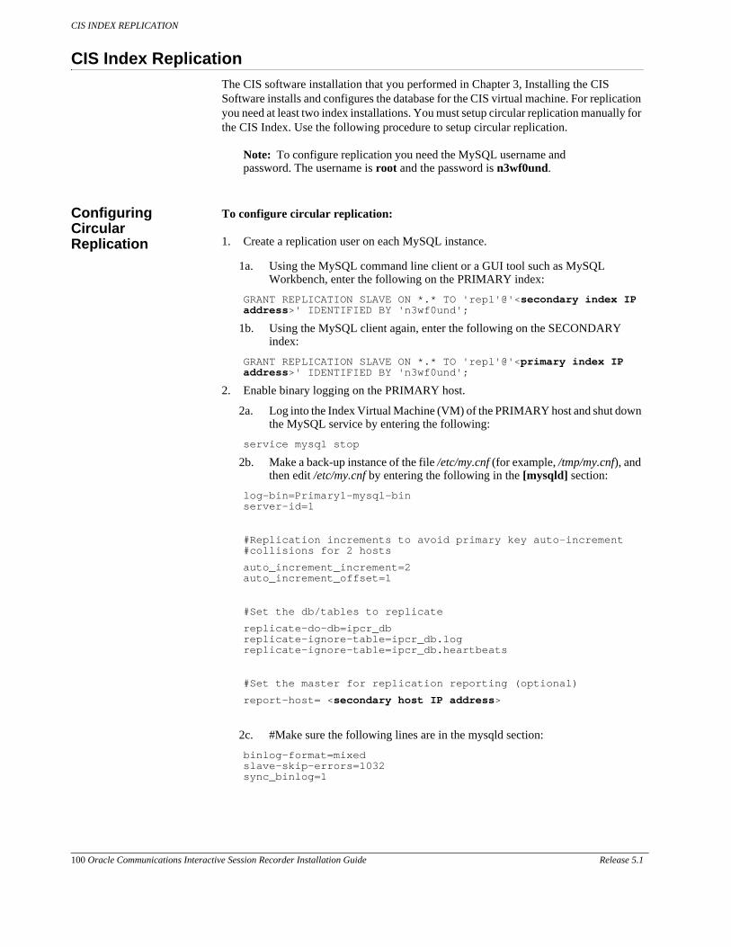
CIS INDEX REPLICATION
100 Oracle Communications Interactive Session Recorder Installation Guide Release 5.1
CIS Index Replication
The CIS software installation that you performed in Chapter 3, Installing the CIS Software installs and configures the database for the CIS virtual machine. For replication you need at least two index installations. You must setup circular replication manually for the CIS Index. Use the following procedure to setup circular replication.
Note: To configure replication you need the MySQL username and password. The username is root and the password is n3wf0und.
Configuring Circular Replication
To configure circular replication:
1. Create a replication user on each MySQL instance.
1a. Using the MySQL command line client or a GUI tool such as MySQL Workbench, enter the following on the PRIMARY index:
GRANT REPLICATION SLAVE ON *.* TO 'repl'@'<secondary index IP address>' IDENTIFIED BY 'n3wf0und';
1b. Using the MySQL client again, enter the following on the SECONDARY index:
GRANT REPLICATION SLAVE ON *.* TO 'repl'@'<primary index IP address>' IDENTIFIED BY 'n3wf0und';
2. Enable binary logging on the PRIMARY host.
2a. Log into the Index Virtual Machine (VM) of the PRIMARY host and shut down the MySQL service by entering the following:
service mysql stop
2b. Make a back-up instance of the file /etc/my.cnf (for example, /tmp/my.cnf), and then edit /etc/my.cnf by entering the following in the [mysqld] section:
log-bin=Primary1-mysql-bin server-id=1
#Replication increments to avoid primary key auto-increment #collisions for 2 hosts
auto_increment_increment=2 auto_increment_offset=1
#Set the db/tables to replicate
replicate-do-db=ipcr_db replicate-ignore-table=ipcr_db.log replicate-ignore-table=ipcr_db.heartbeats
#Set the master for replication reporting (optional)
report-host= <secondary host IP address>
2c. #Make sure the following lines are in the mysqld section:
binlog-format=mixed slave-skip-errors=1032 sync_binlog=1

CIS INDEX REPLICATION
Release 5.1 Oracle Communications Interactive Session Recorder Installation Guide 101
3. Enable binary logging on the SECONDARY host.
3a. Using a secure shell client (SSH), log into the Index VM of the SECONDARY host. Then shut down the MySQL service by entering the following:
service mysql stop
3b. Make a back-up instance of the file /etc/my.cnf (for example, /tmp/my.cnf), and then edit /etc/my.cnf by entering the following in the [mysqld] section:
log-bin=Secondary2-mysql-bin server-id=2
#Replication increments to avoid primary key auto-increment #collisions for 2 hosts
auto_increment_increment=2 auto_increment_offset=2
#Set the db/tables to replicate
replicate-do-db=ipcr_db replicate-ignore-table=ipcr_db.log replicate-ignore-table=ipcr_db.heartbeats
#Set the master for replication reporting (optional)
report-host= <primary host IP address>
3c. #Make sure the following lines are in the mysqld section:
binlog-format=mixed slave-skip-errors=1032 sync_binlog=1
4. Start the MySQL instance on both the PRIMARY and SECONDARY hosts by entering the following:
service mysql start
Warning: Ensure there are no connections to the ISR Record and Store Server (RSS), and that the Dashboard on both primary and secondary hosts is disabled.
5. Using the MySQL client, check the Master status on the PRIMARY host by entering the following:
mysql> FLUSH TABLES WITH READ LOCK; mysql> SHOW MASTER STATUS;
The following is an example of the output from the above commands.
File Position Binlog_Do_DB Binlog_Ignore_DB
Primary1-mysql-bin.000002 98 test manual, mySQL
6. Make a note of the filename and position values from the output table.
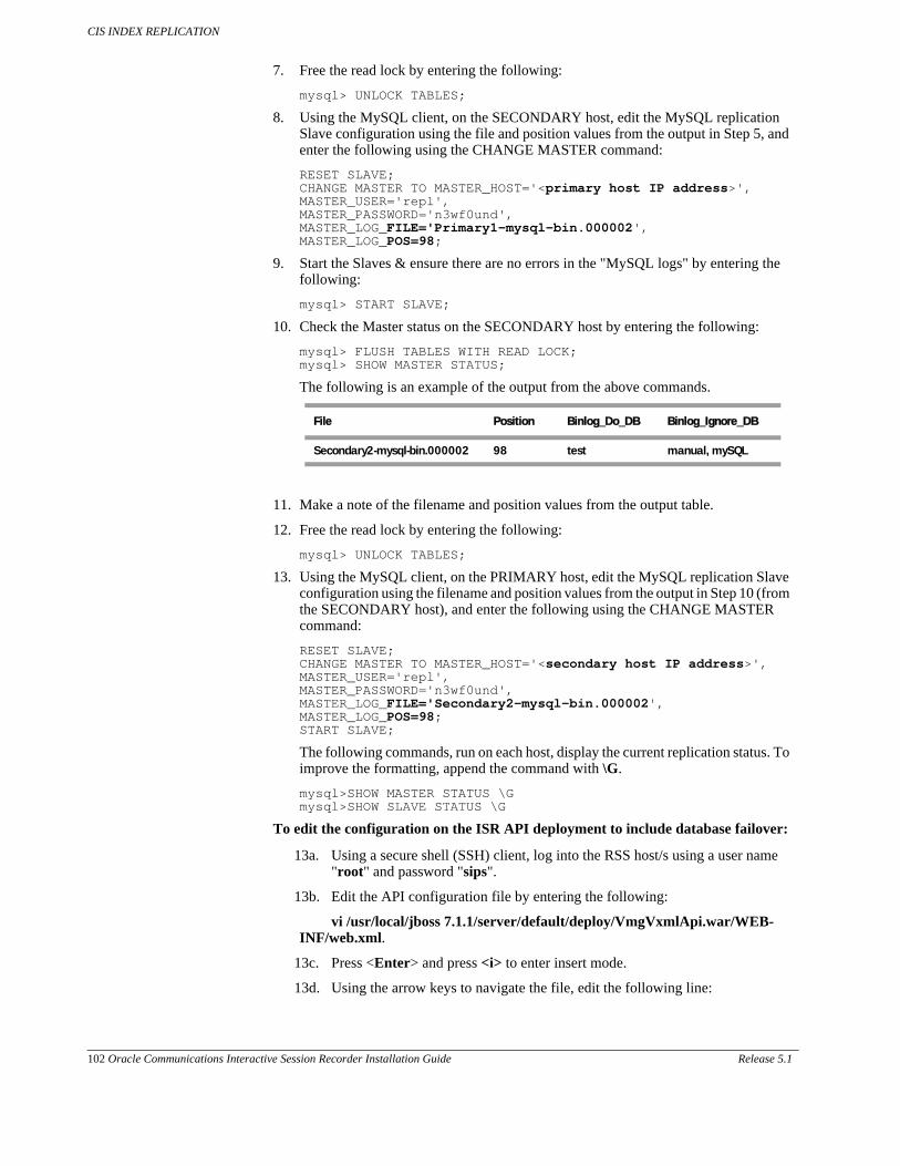
CIS INDEX REPLICATION
102 Oracle Communications Interactive Session Recorder Installation Guide Release 5.1
7. Free the read lock by entering the following:
mysql> UNLOCK TABLES;
8. Using the MySQL client, on the SECONDARY host, edit the MySQL replication Slave configuration using the file and position values from the output in Step 5, and enter the following using the CHANGE MASTER command:
RESET SLAVE; CHANGE MASTER TO MASTER_HOST='<primary host IP address>', MASTER_USER='repl', MASTER_PASSWORD='n3wf0und', MASTER_LOG_FILE='Primary1-mysql-bin.000002', MASTER_LOG_POS=98;
9. Start the Slaves & ensure there are no errors in the "MySQL logs" by entering the following:
mysql> START SLAVE;
10. Check the Master status on the SECONDARY host by entering the following:
mysql> FLUSH TABLES WITH READ LOCK; mysql> SHOW MASTER STATUS;
The following is an example of the output from the above commands.
File Position Binlog_Do_DB Binlog_Ignore_DB
Secondary2-mysql-bin.000002 98 test manual, mySQL
11. Make a note of the filename and position values from the output table.
12. Free the read lock by entering the following:
mysql> UNLOCK TABLES;
13. Using the MySQL client, on the PRIMARY host, edit the MySQL replication Slave configuration using the filename and position values from the output in Step 10 (from the SECONDARY host), and enter the following using the CHANGE MASTER command:
RESET SLAVE; CHANGE MASTER TO MASTER_HOST='<secondary host IP address>', MASTER_USER='repl', MASTER_PASSWORD='n3wf0und', MASTER_LOG_FILE='Secondary2-mysql-bin.000002', MASTER_LOG_POS=98; START SLAVE;
The following commands, run on each host, display the current replication status. To improve the formatting, append the command with \G.
mysql>SHOW MASTER STATUS \G mysql>SHOW SLAVE STATUS \G
To edit the configuration on the ISR API deployment to include database failover:
13a. Using a secure shell (SSH) client, log into the RSS host/s using a user name "root" and password "sips".
13b. Edit the API configuration file by entering the following:
vi /usr/local/jboss 7.1.1/server/default/deploy/VmgVxmlApi.war/WEB-INF/web.xml.
13c. Press <Enter> and press <i> to enter insert mode.
13d. Using the arrow keys to navigate the file, edit the following line:

CIS INDEX REPLICATION
Release 5.1 Oracle Communications Interactive Session Recorder Installation Guide 103
<param-value>jdbc:mysql://<primary host IP address>,<secondary host IP address>/ipcr_db</param-value>
For example:
<param-value>jdbc:mysql://172.30.58.211,172.30.58.171/ipcr_db</param-value>
13e. Press <Esc>, enter “:wq”, and press <Enter>.
Your changes are saved.
13f. Edit the Archiver configuration file by executing the following command:
vi /usr/local/jboss-7.1.1/standalone/deployments.IPCRArchival.sar/META-INF/jboss-service.xml
13g. Press <Enter> and press <i> to enter insert mode.
13h. Using the arrow keys to navigate the file, edit the following line:
<attribute name=”DatabaseUrl”>jdbc:mysql://<primary host IP address>,<secondary host IP address>/ipcr_db</attribute>
For example:
<attribute-name=”DatabaseUrl”>jdbc:mysql://172.30.58.211,172.30.58.171/ipcr_db</attribute>
13i. Press <Esc>, enter “:wq”, and press <Enter>.
Your changes are saved.
13j. Restart the application server by performing the following:
Type "/etc/init.d/jboss stop" and press <Enter>.
Type "/etc/init.d/jboss start" and press <Enter>.
Note: After restarting JBoss, the following line is displayed and can be ignored:
Starting jboss-as: su; Authentication service cannot retrieve authentication info.
14. If required, verify successful failover between the PRIMARY and SECONDARY servers.

CIS INDEX REPLICATION
104 Oracle Communications Interactive Session Recorder Installation Guide Release 5.1

Release 5.1 Oracle Communications Interactive Session Recorder Installation Guide 105
B Mounting a Second RSS Drive for Recordings
The RSS certified hardware specs call for a second drive to be used to store recordings as needed. This can be used for initial storage or short term archival. The following is a procedure for mounting the second drive.
Note: Before performing these procedures, the RSS installation must be complete. For procedures to install the RSS see, Chapter 4, Installing the RSS Software.
Preparing and Mounting a New Second RSS Drive
To mount a second new drive on the RSS for recording storage:
1. Using an SSH application (like Putty), SSH to the RSS server.
2. At the “Login” prompt, enter your login user ID and press <Enter>. Login> root The password prompt displays.
3. Enter your password and press <Enter>. The default password is sips. Password> ********** The “username” prompt displays.
4. Press <Enter> at both the “username” and “password” prompts. The “Access granted since there are no configured users” prompt displays followed by the “NN-ISR>” prompt.
5. Format and mount the drive from the NN-ISR> prompt (OS-E shell): NN-ISR>format data1 ext4
These changes take affect upon restart.
6. Restart the RSS for the changes to take effect. NN-ISR>restart warm Are you sure (y or n)?y ISR is restarting NN-ISR>
Mounting an Existing Pre-Formatted Second RSS Drive
To mount a second existing drive on the RSS for recording storage:
1. Using an SSH application (like Putty), SSH to the RSS server.
2. At the “Login” prompt, enter your login user ID and press <Enter>. Login> root The password prompt displays.

MOUNTING A SECOND RSS DRIVE FOR RECORDINGS
106 Oracle Communications Interactive Session Recorder Installation Guide Release 5.1
3. Enter your password and press <Enter>. The default password is sips. Password> ********** The “username” prompt displays.
4. Press <Enter> at both the “username” and “password” prompts. The “Access granted since there are no configured users” prompt displays followed by the “NN-ISR>” prompt.
5. Format and mount the drive from the NN-ISR> prompt (OS-E shell): NN-ISR>add-device data1 ext4
These changes take affect upon restart.
6. Restart the RSS for the changes to take effect. NN-ISR>restart warm Are you sure (y or n)?y ISR is restarting NN-ISR>
Editing the vmgConfig.xml File
After completing the procedures in Mounting a Second RSS Drive for Recordings, you can make the new drive the primary location for which the RSS writes recordings. To do this, you must edit the vmgConfig.xml file. Use the following procedure to edit the vmgConfig.xml file.
Note: For vmgConfig.xml parameter descriptions, see Appendix F, vmgConfig.xml Parameters.
To edit the vmgConfig.xml file:
1. Enter shell and press <Enter>. NN-ISR> shell The shell prompt displays. The remaining steps show examples of the shell prompt and output displays for each command entered.
2. Enter vi vmgConfig.xml and press <Enter> to open the XML file. <hostname> # vi vmgConfig.xml The file opens and displays the contents of the file in the window.
3. Enter i and press <Enter> to enter the editing mode. <hostname> # i
Line 6 in the XML file is the initial location for all recordings. <Location>/cxc_common/ISR/Recordings</Location>
4. Edit Line 6 to read <Location>/<Directory Name></Location>, replacing Direcotyr Name with the mount point created in the process step. For example, <hostname> # <Location>/ArchivedRecordings</Location>
5. Press <Esc>, then type “:wq”, and press <Enter>. The shell prompt displays.
6. Enter exit to exit the shell. The “NN-ISR>” prompt displays.
Enter restart processor for the RSS to use this new configuration. NN-ISR> restart processor ISR

MOUNTING A SECOND RSS DRIVE FOR RECORDINGS
Release 5.1 Oracle Communications Interactive Session Recorder Installation Guide 107
The ISR restarts.
7. After the ISR is up and running, perform Steps 1 through 4 to open a shell on the ISR.
8. Enter less /cxc_common/ISR/ISRLogs/ISR.log and press <Enter> to open the ISR.log file. <hostname> # less /cxc_common/ISR/ISRLogs/ISR.log The contents of the ISR.log file display.
9. Press the <space bar> to move the file forward. The currently configured recording location displays. For example:
10/04/2011 06:01:23[NOTICE] mixMaster: Recordings Directory = /ArchivedRecordings

MOUNTING A SECOND RSS DRIVE FOR RECORDINGS
108 Oracle Communications Interactive Session Recorder Installation Guide Release 5.1

Release 5.1 Oracle Communications Interactive Session Recorder Installation Guide 109
C Configuring RAID on the CIS and RSS Servers
Redundant Arrays of Inexpensive Disks (RAID) is a combination of multiple small, inexpensive disk drives into an array of disk drives which yields performance exceeding that of a single drive. This array of drives appears to the computer as a single logical storage unit or drive.
There are 6 levels of RAIDS (RAID 0 through RAID 5). The CIS and RSS certified hardware servers support RAID 1 and RAID 5. RAID Level 1 provides redundancy by writing all data to two or more drives. RAID Level 5 distributes parity among the drives.
You must configure the additional (likely 4 900GB) disks for RAID before performing the CIS and RSS installations. Use the procedure in this Appendix to configure RAID on the CIS and RSS servers before attempting the CIS and RSS installation process.
Configuring RAID On the HP DL360 Gen8 ServerThere are multiple approaches to configuring the logical drives on the HP DL360 Gen8 servers available.
Note: One straight-forward option, not documented here, is “HP Intelligent Provisioning”.
The following procedure uses the Option ROM Configuration for Arrays (ORCA):
1. Power up and boot the server. After the “HP ProLiant” boot screen, press F9 to see the remaining configuration options available. the following message displays:
2. Press F8 when the remaining options scroll in the messages feed to run “Option ROM Configuration for Setup Arrays”.
Note: In the ORCA main menu the number of logical drives should be “2”. However, on first bootup of the server, it is typically “1”. If there are “2” logical drive sets, you are finished with this procedure. If there is “1” logical drive, continue to Step 3.

CONFIGURING RAID ON THE CIS AND RSS SERVERS
110 Oracle Communications Interactive Session Recorder Installation Guide Release 5.1
3. Press <F8> to enter the Option ROM Configuration for Arrays Menu”. The following menu displays: Create Logical Drive View Logical Drive Delete Logical Drive Select Boot Volume Manage License Keys Cache Settings
4. Select “View Logical Drive”. The following information displays: Logical Drive #1 Raid 1, 299.96 GB
5. Press <Esc> to return to the Main Menu.
6. Select “Create Logical Drive”. The output information shows the drives that are not currently part of an existing logical drive.
7. Verify all four physical drives are selected, tab to the RAID Configuration table, and select RAID 1+0.
8. Press <Enter> to create the volume on the server and press F8 to save the configuration. The volume size is approximately 1.8 TB with the remaining 1.8 TB used for the mirrored volume.
9. Select “View Logical Drive” from the Options Menu to view the logical drive you created.
10. Select <Exit> to exit the Options Menu and continue the bootup process.
Note: On the CIS, the 1.8 TB partition is used as storage for the VMs, specifically the database. On the RSS, the 1.8 TB partition is used to store Recordings.
Configuring RAID On the HP DL360 G7 ServerUse the following procedure to configure RAID on the CIS and/or RSS server.
To configure RAID:
1. Power up and boot the server. After the “HP ProLiant” splash screen, the following message displays:
“Press any key for ROM Message Options”.
2. Press any key so you can see the remaining boot options.
The startup messages and configuration options for the various hardware components display. The first option presented is the Hewlitt Packard Integrated Lights Out (HP ILO) service. If you want to use this service, you can find more information about configuring JP ILO on the HP website.
The RAID controller starts up and the following prompt displays:
Slot HP Smart Array P41i Controller # Logical Drives:
The number of logical drives should be 2. However, on first bootup of the server, it is typically 1.
Note: If there are 2 logical drive sets, you are finished with this procedure. If there is 1 logical drive, continue to the next step.
3. Press <F8> to enter the Option ROM Configuration for Arrays Menu”. The following menu displays:

CONFIGURING RAID ON THE CIS AND RSS SERVERS
Release 5.1 Oracle Communications Interactive Session Recorder Installation Guide 111
Create Logical Drive View Logical Drive Delete Logical Drive Select Boot Volume Manage License Keys Cache Settings
4. Select “View Logical Drive”. The following information displays: Logical Drive #1 Raid 1+0, 73.37 GB
5. Press <Esc> to return to the Main Menu.
6. Select “Create Logical Drive”. The output information shows the drives that are not currently part of an existing logical drive. The default RAID configuration for each server is as follows:
Server Number of Drives Drive Size EachDefault RAID Configuration
CIS 4 600GB RAID 5
RSS 2 300GB RAID 1 and 0
7. Press <Enter> to create the volume on the server. The volume size is approximately 300GB with the remaining 300GB used for the mirrored volume.
8. Select “View Logical Drive” from the Options Menu to view the logical drive you created.
9. Select <Exit> to exit the Options Menu and continue the bootup process.
Note: On the CIS, the 1.8 TBpartition is used as storage for the VMs, specifically the database. On the RSS, the 1.8 TB partition is used to store Recordings.

CONFIGURING RAID ON THE CIS AND RSS SERVERS
112 Oracle Communications Interactive Session Recorder Installation Guide Release 5.1

Release 5.1 Oracle Communications Interactive Session Recorder Installation Guide 113
D CIS Troubleshooting
This Appendix provides FAQs and additonal information regarding the CIS components for your reference.
vSphere Hypervisor
Q. How do I manage the virtual machine (VM) host?
A. You use the VMware vSphere client to monitor and configure the VM host. To install the vSphere client, see Chapter 3, Installing the CIS Software.
Q. What operating system do the virtual machines use?
A. All VMs use the Oracle Linux Server release 6.4.
Q. How do I monitor and manage the virtual machines?
A. You use the VMware vSphere client to monitor and configure the VMs. To install the vSphere client, see Chapter 3, Installing the CIS Software.
Q. What user and password is used to login on the guest OS?
A. All VMs have a "gansett" user with password "n3wf0und".
Q. What is the root password on the guest OS?
A. The root password for the guest OS is "64^5377".
A. Do I need to configure the database URL for the dashboards?
A. No. There is a local VM network (named VM Local) that includes the database VM (named "index") with IP address 192.168.1.50, and Dashboard VM (named "dashboard") on 192.168.1.25. These settings and the "VM Local" virtual network remain static.
A. How do I download files from a virtual host?
A. SSH file transfers with an SFTP client such as Filezilla using the root user and password gains access to any file on the system.

CIS TROUBLESHOOTING
114 Oracle Communications Interactive Session Recorder Installation Guide Release 5.1
Index Virtual Machine
A. What version of MySQL Server is installed with the CIS?
A. The MySQL Server version is 5.5.31, for Linux (x86_64).
A. How do I connect directly to the CIS database in MySQL Server?
A. If the index VM was configured with a static IP on the VM Network, you can connect to the 'ipcr_db' database from a MySQL client with user 'ipcr_admin' and password 'n3wf0und'.
Root access to MySQL server is possible only from mysql's command line client in the index VM connecting as 'root' with password 'n3wf0und'.
A. How do I view the logs in MySQL Server?
A. MySQL Server's log file can be found in the directory /var/lib/mysql.log. The main log file is named <host_name>.err. The error log can be found in the directory /var/lib/mysql/index.err.
If configured to do so, slow query logs can be found in the directory /var/lib/mysql/index-slow.log.
Note: All ISR-related errors are found in the respective component logs.
Q. How do I log slow queries in MySQL Server?
A. To start logging slow queries without restarting mysql server, execute the following:
1. At MySQL command prompt, enter set global slow_query_log=1.
2. Enter set global long_query_time=1 (or whatever you want for query seconds).
3. To verify the settings for these commands, use the following show variables: %slow% %length% By default, the slow query logs are stored in the directory /var/lib/mysql/index-slow.log.
Q. How do I find the data files in MySQL Server?
A. Data files for the 'ipcr_db' database are found in the directory /var/lib/mysql/ipcr_db/.

CIS TROUBLESHOOTING
Release 5.1 Oracle Communications Interactive Session Recorder Installation Guide 115
Dashboard Virtual Machine
Q. How do I log in to the ISR Dashboard?
A. Perform the following:
1. Open your Internet Web browser.
2. Enter the IP address of the ISR. For example:http://172.54.66.7
The Login page displays.
3. Enter your email and password, respectively, in the “Email” and “Password” fields.
The default user name and password are:
User name: [email protected] Password: admin123
Note: You are required to change the default password, admin123, upon initial login and then again every 90 days.
Q. How do I find the version of the ISR Dashboard?
A. The ISR Dashboard version number is shown on the bottom border of all pages in the graphical user interface (GUI).
Q. How do I troubleshoot problems with the web interface on the Dashboard VM?
A. A common error during Dashboard deployment leaves the Dashboard unable to connect to the Index VM database. If browsing to the Dashboard IP results in the display of a “500 Internal Server Error” message (for example, in Chrome “HTTP Error 500 (Internal Server Error): An unexpected condition was encountered while the server was attempting to fulfill the request.”), the error should be described in the Dashboard application log.
To access the application log:
1. Access the Dashboard VM shell.
2. Enter less /var/www/dashboard/current/log/production.log.
3. Enter G to scroll to the bottom of the log.
4. Scroll up the file looking for the following lines:
Status: 500 Internal Server Error
Can’t connect to MySQL server on ‘169.254.1.50’ (113)
5. Enter q to exit.
6. Enter ping 169.254.1.50.
7. If the following appears:
PING 169.254.1.50 (169.254.1.50) 56(84) bytes of data
From 169.254.1.50 icmp_seq=2 Destination Host Unreachable.
<Ctrl> C to discontinue the ping and check the network service status and connections on the Index host’s eth1 interface.

CIS TROUBLESHOOTING
116 Oracle Communications Interactive Session Recorder Installation Guide Release 5.1
CIS Networking
Q. How do I add a separate network, for example a separate network for voice traffic?
A. Using the vSphere client, perform the following:
1. Log in to the vSphere client application.
2. Click on the Configuration tab for the ESXi host.
3. Click on Hardware->Networking.
4. Click Add Networking…" in the top right corner
5. In the Add Network Wizard, complete the following steps:
• Verify the Virtual Machine radio button is selected and hit <Next>.
• Click the check-box of the appropriate NIC and click <Next>. The appropriate NIC has a "Speed" column value that is not "Down", for example, "1000 Full". In addition, the NIC has a "Network" column value that contains the range of IPs expected on that network.
• Edit the "Network Label"; for example, "VM Voice", and click <Next>.
• Review and click <Finish>.
6. Right-click on the VM where the network is being added.
7. Click "Edit Settings…" and complete the following:
• In the properties window, click <Add>.
• Select "Ethernet Adapter" and press <Next>.
• Select the proper "Network Connection" from the pull-down menu; for example, "VM Voice".
• Review and click <Finish>.
8. Select the VM for adding the network, and execute the following:
• Click on the "Console" tab and click in the main panel. Your mouse is confined to the console panel.
• Press <Alt>+<Ctrl> to release.
• Log into the VM with the root password root/<root_password>.
• Copy the first network config as a template for the third interface: cp /etc/sysconfig/network-scripts/ifcfg-eth0 /etc/sysconfig/network-scripts/ifcfg-eth2
9. Set the IP of the VM by editing the file ifcfg-eth2 as follows:
• Enter vi /etc/sysconfig/network-scripts/ifcfg-eth2 and press <Enter>.
• Press <i> to enter insert mode.
• Change DEVICE=”eth2”.
• Change IPADDR=<your Index IP> (on VM voice network).
• Change GATEWAY=<network gateway>.
• Change DNS1=<network DNS>.
• Change DNS2=<network secondary DNS>.

CIS TROUBLESHOOTING
Release 5.1 Oracle Communications Interactive Session Recorder Installation Guide 117
• Change NAME=”System eth2”.
• Press <Esc>, then type “:wq”, and press <Enter>.
10. Delete the UDev rules for the network interfaces as follows:
• Type “rm -f /etc/udev/rules.d/70-persistent-net.rules”.
11. Restart the host for the interface to automatically be added as follows:
• Type “shutdown -r now”.
Note: Executing this command reboots the system, so it is important to do this with no live traffic.
12. Log in to the VM again and ping an appropriate IP address to verify the new interface.
Q. How do I add a second Ethernet adapter on the same network, (also known as NIC teaming)?
A. Perform the following:
1. Verify the cable connection and green light on the physical interface.
2. Using the vSphere client, execute the following:
• Click on the Host IP or name on the list in the left panel.
• Click on the "Configuration" tab in the main panel.
• Click the Hardware->Networking.
• Find the "Virtual Switch", for example, “vSwitch0”, containing the labeled network to which the new network adapter will be added, and click the "Properties" link next to that "Virtual Switch".
• In the vSwitch Properties window, click the "Network Adapters" tab.
• With the proper adapter highlighted, click <Add>.
• In the "Add Adapter Wizard" click the check-box of the appropriate NIC and click <Next>. The appropriate NIC has a "Speed" column value that is not "Down", for example, "1000 Full". In addition, the NIC has a "Network" column value that contains the range of IPs expected on that network.
• Verify both adapters are in the "Active Adapters" group and click <Next>.
• Review the list and click <Finish>. The second "Physical Adapter" icon displays next to the labeled network indicating that the second Ethernet adapter is now on the same network.

CIS TROUBLESHOOTING
118 Oracle Communications Interactive Session Recorder Installation Guide Release 5.1

VMGCONFIG.XML PARAMETERS
Release 5.1 Oracle Communications Interactive Session Recorder Installation Guide 119
E vmgConfig.xml Parameters
This Appendix provides the parameters, the supported values, and the description of each parameter in the vmgConfig.xml file. Refer to this appendix as required when editing the vmgConfig.xml file.
XML Parameters Supported Values Description
<NumberOfChannels>500</NumberOfChannels> 1 - 500 The number of sessions that should be started on this device. This parameter is restricted by the license file.
<Recording>
<FullCallRecording>disabled</FullCallRecording><Location>/cxc_common/ISR/Recordings</Location>
<AlternativeLocation>/cxc_common/ISR/ArchivedRecordings </AlternativeLocation>
<ThirdLocation/>
<FileNameFormat>%DNIS%-%CALLID%.wav</FileNameFormat>
enabled, disabled
accessible directory
accessible directory
accessible directory
text
enabled = ISR will not use recording rules, index recordings. It will record all traffic received and put files named <FileNameFormat> in <Location>. disabled = ISR uses other sources to ascertain how sessions should be recorded. This Is the standard behavior.
The location where recordings made on this RSS will be written. This is normally the RSS itself.
An alternate location where recordings will be written. If <Location> is changed to a remote storage device, <AlternativeLocation> would allow you to specify a fallback location in the event <Location> is not accessible. When <Location> is on the RSS, <AlternativeLocation> is not needed.
A third alternate location where recordings are written. If <Location> is changed to a remote storage device, <ThirdLocation> would allow you to specify a fallback location in the event <Location> and <AlternativeLocation> are not accessible. When <Location> is on the RSS, <ThirdLocation> is not needed.
Any combination of letters and numbers, - (dash) and _ (underscore) along with system variables %DNIS%, %ANI%, %CALLID%, %DATE% that will be used as the default naming convention for files.

VMGCONFIG.XML PARAMETERS
Release 5.1 Oracle Communications Interactive Session Recorder Installation Guide 120
<Format><RIFFHeader>enabled</RIFFHeader>
<Encoding>linear</Encoding>
<BitRate>8</BitRate>
<NumberOfChannels>1</NumberOfChannels>
<SeparateFilePerChannel/></Format>
<BeepOnRecord><BeepFile>beep.wav</BeepFile>
<BeepIntervalSeconds>10</BeepIntervalSeconds>
<BeepOnRecordState>disabled</BeepOnRecordState>
<BeepDirection>ToCaller</BeepDirection></BeepOnRecord>
</Recording>
enabled, disabled
linear, ulaw, alaw, adpcm
8,16
1, 2
true, false
name of an 8bit 8KHz ulaw file
numbers
enabled, disabled
ToCaller, ToCalledParty, ToBoth
Insert RIFF Header on WAV recordings
1 = mono2 = stereo
By default, with no parameter, this is disabled. Set to true, <SeparateFilePerChannel>true</SeparateFilePerChannel>, if you want your stereo recording to be in 2 separate files, caller in one file, called party in the other. Used in broadcast implementations. IMPORTANT -- with this enabled , calls can not be played back through the Acme provided dashboards.
File that should be played when beep tone is enabled. This file needs to be placed in the <LocalRepository> directory specified in the Cache section of this file.
Time, in seconds, between each beep, when enabled in the dashboard.
This flag is obsolete. Beep enabled/disabled in AdminDashboard on route by route, account by account basis.
Specify who should hear the intermittent beep tone.
XML Parameters Supported Values Description

VMGCONFIG.XML PARAMETERS
Release 5.1 Oracle Communications Interactive Session Recorder Installation Guide 121
<Sip><SipPort>5060</SipPort>
<FromFormat>%ANI%@%IP%:%PORT%;channel=%CHANNEL%; call-id=%CALLID%</FromFormat>
<ToFormat>%DNIS%@%IP%:%PORT%</ToFormat>
<RejectionSubstitutionCode>-1</RejectionSubstitutionCode>
<RegistrarAddress/>
<RegistrarUserName/>
<RegistrarExpires>0</RegistrarExpires>
<AuthenticationUserId/>
<AuthenticationPassword/>
<AuthenticationRealm/>
<InviteTimeout>75</InviteTimeout>
<TransferInviteTimeout>75</TransferInviteTimeout>
<SipProxyAddress/>
<ForwardHoldRequest>disabled</ForwardHoldRequest>
<Supported><Headers/>
<ComfortNoise/></Supported>
<AuthorizedIncomingGateways><Host/>
</AuthorizedIncomingGateways></Sip>
valid SIP URI
valid SIP URI
Any valid SIP response
IP/FQDN of Registrar
text
numeric
text
text
text
1 - 180
1 - 180
enabled, disabled
SIP Header
Port RSS is listening for SIP Traffic.
Format of FROM header to be used on INVITES FROM the RSS back to the Outbound Session Agent. channel and callid are useful for API implemetnations. They should not be removed.
Format of TO header to be used on INVITES FROM the RSS back to the Outbound Session Agent.
Error Message to be sent back in the event the RSS is unable to accept a call. Overrides all Error responses. -1 indicates no override, use standard rejection message.
IF RSS must register as endpoint, what address should it register with.
Registrar User Name
Registar Expiration. Default is no expiration.
User ID for Challenge Authentication
Password for Challenge Authentication
Realm for Challenge Authentication
Timer, in seconds, for how long RSS will wait for 18x message on an INVITE
Timer, in seconds, for how long RSS will wait for 18x message on an REFER
Header name that should be taken from incoming INVITE and added to outgoing INVITE
With no values, RSS accepts all incoming INVITEs and evaluates for recording. To restrict devices, enumerate.
XML Parameters Supported Values Description

122 Oracle Communications Interactive Session Recorder Installation Guide Release 5.1
VMGCONFIG.XML PARAMETERS
<XmlRpc><ServerPort>8888</ServerPort>
<AllowedHosts>
<Host/>
</AllowedHosts>
<QueryAgent>
<Enabled>true</Enabled>
<Host>localhost</Host>
<Port>8887</Port>
<SkipVoiceBrowserMode>enabled</ SkipVoiceBrowserMode>
<LocalRouteMapCache>enabled</LocalRouteMapCache>
<LocalRouteMapCacheUpdateInterval>300</ LocalRouteMapCacheUpdateInterval>
</QueryAgent>
</XmlRpc>
true, false
IP/FQDN
port
enabled, disabled
enabled, disabled
time, seconds
Port where XML RPC server is listening. This should not be changed.
Hosts that should be allowed to issue API commands
If true, RSS will connect to CIS to get recording rules. If false, RSS expects that either <FullCallRecording> is enabled OR <SkipVoiceBrowserMode> is disabled. DO NOT EDIT UNLESS DIRECTED.
IP Address of XMLRPC Query Agent. Is installed on each RSS host. DO NOT EDIT UNLESS DIRECTED.
Port for XMLRPC Query Agent. DO NOT EDIT UNLESS DIRECTED.
If disabled, RSS will issue INVITE to address specified in <IVRGateway> for recording rules. This is the RSS 1.4 implementation and is here for backwards compatibility. DO NOT EDIT UNLESS DIRECTED.
If disabled, RSS will need to communiate with CIS on every call, which could impact performance. DO NOT EDIT UNLESS DIRECTED.
Interval, in seconds, that RSS should attempt to refresh the route map cache and read in changes in the CIS. 5 minutes is the default. This is the maximum amount of time that will elapse before a change in the AdminDashboard will be applied to incoming sessions.
XML Parameters Supported Values Description

VMGCONFIG.XML PARAMETERS
Release 5.1 Oracle Communications Interactive Session Recorder Installation Guide 123
<TransferDropOutMode>disabled</TransferDropOutMode>
<Rtp><ListenPortStart>22000</ListenPortStart>
<SendPortStart>32000</SendPortStart>
<MinimumPacketSize>1</MinimumPacketSize>
<MaximumPacketSize>160</MaximumPacketSize>
<RtpInCheckPacketSource/>
<TransferMuteAudio/>
<MissingMediaDetection>
<SessionEstablishment>
<WarnAfterSeconds>10</WarnAfterSeconds>
<TerminateSessionAfterSeconds>300</TerminateSessionAfterSeconds>
</SessionEstablishment
</SessionInProgress
<WarnAfterSeconds>10</WarnAfterSeconds>
<TerminateSessionAfterSeconds>300</TerminateSessionAfterSeconds>
</SessionInProgress
</MissingMediaDetection>
</Rtp>
disabled, enabled
1 - 66535
1 - 66535
Should the RSS drop out of the call when a request to transfer is received? If disabled, RSS will continue to record. If enabled, RSS will remove itself from the call path on transfer request.
XML Parameters Supported Values Description

VMGCONFIG.XML PARAMETERS
Release 5.1 Oracle Communications Interactive Session Recorder Installation Guide 124
<IvrGateways><Host/>
</IvrGateways>Fallback Session Agent IP address in the event RSS can't build initial Session Agent Cache from CIS
<VMGIpAddress></VMGIpAddress>
<LocalCallDetailRecord>disabled</LocalCallDetailRecord>
<EarlyMediaAllow>true</EarlyMediaAllow>
IPv4 Address
enabled, disabled
true, false
Must be specified when there are multiple network interfaces confiugred on an RSS server. Tells the RSS which address it should use for all egress traffic.
Should Early Media (RTP received before 200OK) be forwarded or dropped
<Cache><NumberOfCacheEntries>256</NumberOfCacheEntries>
<LocalRepository>/cxc_common/ISR/Cache/</ LocalRepository>
<RemoteRepositoryURL>http://loudeye.com/muzak/ get_some.php</RemoteRepositoryURL>
</Cache>
1 - 256
directory
Number of files RSS should hold in its cache before the oldest file is removed and replaced with a newer request.
Directory where Cached files should be stored.
Not currently supported.
<FailOver><Mode/>
<GatewayToInvite/>
<MessageFile/>
<MessageFile/></FailOver>
LEGACY SUPPORT ONLY. DO NOT EDIT UNLESS DIRECTED.
LEGACY SUPPORT ONLY. DO NOT EDIT UNLESS DIRECTED.
LEGACY SUPPORT ONLY. DO NOT EDIT UNLESS DIRECTED.
LEGACY SUPPORT ONLY. DO NOT EDIT UNLESS DIRECTED.
<PortCapacity><NumberOfPortCapacityLines>0</NumberOfPortCapacityLines>
<MessageFile/>
<Loop/></PortCapacity>
LEGACY SUPPORT ONLY. DO NOT EDIT UNLESS DIRECTED.
LEGACY SUPPORT ONLY. DO NOT EDIT UNLESS DIRECTED.
LEGACY SUPPORT ONLY. DO NOT EDIT UNLESS DIRECTED.
XML Parameters Supported Values Description

VMGCONFIG.XML PARAMETERS
Release 5.1 Oracle Communications Interactive Session Recorder Installation Guide 125
<Sip><IsrUcidHeaderField> X-ISR-UCID </IsrUcidHeaderField>
</Sip>
Configures the X-ISR-UCID header field in SIP INVITE messages.
<Siprec><SiprecEnabled/>
</Siprec>
true, falseEnables or disables SIPREC support. The default is false.
XML Parameters Supported Values Description

VMGCONFIG.XML PARAMETERS
Release 5.1 Oracle Communications Interactive Session Recorder Installation Guide 126

Release 5.1 Oracle Communications Interactive Session Recorder Installation Guide 127
F Selective Call Recording/SIPREC
What is SIPREC?
The SIPREC protocol is the protocol used to interact between a Session Recording Client (SRC) (the role performed by ESD) and a Session Recording Server (SRS) (a 3rd party call recorder or the ISR’s Record and Store Server (RSS)). It controls the recording of media transmitted in the context of a communications session (CS) between multiple user agents.
SIPREC provides a selective-based call recording solution that increases media and signaling performance on 3rd party call recording servers, more robust failovers, and the ability to selectively record.
Note: 1. SIPREC isolates the 3rd party recorders from the communication session. The 3rd party recorders can determine whether or not recording is desired. 2. The SRC starts a recording session for every call within a configured realm. All call filtering, if desired, must be accomplished by the SRS. The SRS performs the filtering and selection of which sessions it should record.
License/Hardware Requirements
SIPREC requires the purchase of a Session Recording license. Contact your Acme Packet Representative for more information.
SIPREC is currently supported on the following platforms running Acme Packet Release E-C(xz)6.4.0F1:
• 3820
• 4500
• Enterprise Session Director-Server Edition (ESD-SE)
• Enterprise Session Director-Virtual Machine Edition (ESD-VME)
How it Works
The SIPREC feature supports active recording, where the ESD acting as the SRC, purposefully streams media to the ISR’s RSS (or 3rd party call recorder) acting as the SRS. The SRC and SRS act as SIP User Agents (UAs). The SRC provides additional information to the SRS to describe the communication sessions, participants and media streams for the recording session to facilitate archival and retrieval of the recorded information.

SELECTIVE CALL RECORDING/SIPREC
128 Oracle Communications Interactive Session Recorder Installation Guide Release 5.1
The ESD acting as the SRC, is the source for the recorded media. The ESD consumes configuration information describing the ecosystem within which it operates. The interface, realm and session agent configuration objects specify the SIPREC configuration. A SIP UA can elect to allow or disallow any network element from recording its media.
During the establishment of a SIP Session, the ESD determines if SIPREC is configured for recording the call. If so, it then duplicates the media prior to initiating the session with the SRS. (Media replication is set up prior to the recording session). The SRS may choose to record, not record, or cancel the recording session, and then communicates via SIP signaling to the ESD. If the call is not to be recorded, the SRS signals termination of the recording session.
The ESD maintains SIPREC metadata information associated with recording sessions. The recording session metadata describes the current state of the recording session and its communication session(s). It is updated when a change of state in the communication session(s) is observed by the ESD. The SRS is responsible for maintaining call history, etc. The ESD creates and logs call detail records (CDRs) in the current manner, the 3rd party SRS vendor may collate this information if desired. (For more information about the contents of metadata, see Metadata Contents (137)).
The following illustration shows two endpoints, User Agent A (UA-A) and User Agent B (UA-B). Their session is being recorded by an SRC (the ESD) and an SRS.

SELECTIVE CALL RECORDING/SIPREC
Release 5.1 Oracle Communications Interactive Session Recorder Installation Guide 129
Configuring SIPREC
This section defines the information required to configure SIPREC on the ESD. It also provides a sample procedure for configuring SIPREC using the Acme Packet Command Line Interface (ACLI).
Session Recording Server (SRS)
The ISR’s RSS acts as the SRS in the network. A session-recording-server attribute under the session-router object in the ESD ACLI allows you to enable/disable the SRS. This object is the session recording server that receives replicated media and records signaling. Additional parameters for SRS are configured under the session-agent, realm-config, and sip-interface objects. The rules of precedence for which the ESD uses these parameters are: session-agent takes precedence over the realm-config, and realm-config takes precedence over sip-interface.
Each SRS is associated with a realm-config. The realm specifies the source interface from which replicated traffic originates. The destination is an IP Port parameter (IP address or hostname with an optional port) that defines the SIP address (request URI) of the actual SRS.
For an additional level of security, Acme Packet recommends the SRS be configured in its own realm so as to apply a set of access control lists (ACLs) and security for the replicated communication.
Although the ESD supports large UDP packets, Acme Packet recommends the sip-interface associated with the SRS realm, be provisioned with a TCP port.
Session Recording Group
The ESD uses the session-recording-group attribute under the session-router object in the ACLI to set high availability (HA) for 3rd party call recorders. Using this object, you can define a collection of one or more SRSs. The ESD utilizes SIP’s transport mechanism and keeps track of statistics on each SRS to manage the distribution of traffic and load balancing. (For more information on ESD load balancing in session recording groups, see Load Balancing (130)). When multiple SRSs are in a session recording group, the ESD uses heuristics to intelligently route the recording dialog to one or more SRSs utilizing the selection strategy.
The simultaneous-recording-servers configuration attribute controls the number of simultaneous SIP dialogs that the ESD establishes to the SRSs in the session recording group per communication session. For instance, if a session recording group contains 3 SRSs, and simultaneous-recording-servers is set to 2, the recording agent initiates a SIP INVITE to the next two SRSs based on the session recording group strategy. In this way, duplicative recording sessions are instantiated, allowing for recording redundancy in multiple SRSs or within a session recording group.
Note: The ESD streams media to all SRSs. Each SRS chooses whether or not to ignore the media by returning a “recvonly”(receive only) media line. This permits an SRS to select specific media to record in the recording session, as well as determine whether or not to record the media.

SELECTIVE CALL RECORDING/SIPREC
130 Oracle Communications Interactive Session Recorder Installation Guide Release 5.1
The number of simultaneous recording servers does not dictate the number of recording devices required to be active for a communication session. If two SRSs exist in a session recording group and simultaneous-recording-servers is set to 2, if at least one recording device to any of the servers completes, the recording server is treated as being established.
Load Balancing The ESD supports recording server load balancing across members of a session recording group using the following strategies:
[Round-robin]: The ESD remembers the last SRS that was used. Each new recording session selects the next SRS in the session recording group. When simultaneous-recording-servers is greater than 1, the next n recording servers are selected from the session recording group.
[hunt]: The ESD successively attempts to contact SRSs in the session recording group until a successful recording dialog is established with the SRS, starting from the first SRS in the session recording group. The ESD attempts to contact each SRS in the session reporting group once. When contact is exhausted, the recording device is considered failed. A SIP failure (response greater than 399, timeout or TCP setup failure) causes the ESD to attempt the next possible SRS. When simultaneous-recording-servers is greater than 1, the ESD attempts to establish n recording devices in a hunting fashion.
[least busy]: For some 3rd party recording devices, the number of concurrent recording servers proves to be the most taxing for system resources. The ESD tracks the number of recording servers active to a given SRS at any given time. It uses this information to determine which SRS would be the best candidate for the next RS. The SRS with the fewest number of active recording servers receives the next RS. If two or more SRSs in a session recording group currently have the same number of active recording servers, the SRS configured first in the session recording group takes precedence.
[lowest sustained rate (fewest-setups-per-minute)]: For some 3rd party recording servers, processing large amounts of sessions in a short amount of time proves to be the most taxing on their system's resources. The ESD tracks the number of recording server setups over a sliding window of five minutes. The SRS within the session recording group with the fewest setups per the window of time is selected as the next candidate for receiving the recorded session. If two or more SRSs in a session recording group currently have the same value for setups in the given window of time, then the SRS configured first in the session recording group takes precedence.
Session Recording Group within Logical Remote Entities
Each logical remote entity (session-agent, realm-config and sip-interface) has a session-recording-server attribute.This attribute is a reference to a specific SRS configuration and can be used to specify a session recording group instead. If a session recording group is specified instead of an SRS, the session recording group name must be prefixed with "SRG:" followed by the session recording group name. This distinguishes between an SRS being referenced and a session recording group being referenced.
When the ESD is configured for legacy SRR features, it is possible to configure a call recording server on both the ingress and egress realms. If configured, the ESD uses the egress call recording server to record. However, with SIPREC, this process works differently. With SIPREC, if an SRS or session recording group is configured on both the ingress and egress logical remote entities, both the ingress and egress SRS/session recording groups are used. This means that the ESD records the media between participants twice (or more) - once for the ingress recorders and once for the egress recorders.

SELECTIVE CALL RECORDING/SIPREC
Release 5.1 Oracle Communications Interactive Session Recorder Installation Guide 131
If both the ingress and egress SRS/session recording group are the same, the ESD makes an optimization and only records the media once. Even if the ingress session recording group is the same exact set of SRSs as the egress session recording group (but with a different name), the ESD replicates media to both destinations. However, if the same set of SRSs has the exact same identifier, the ESD sends media to one and not both SRSs.
Selective Recording
SIPREC defines a number of use cases for which the ESD can record communication sessions. These use cases include the use of selective based recording. A selective recording is one in which a unique recording server is created per communication session.
Note: The ESD does not support persistent recording.
For SRSs using selective recording, recording servers are unique per session recording group. For each selective SRS in a session recording group, during the setup of a new communication session, the recording metadata is the same for each recording device. The SRC initiates a new SIP INVITE to the SRS carrying the metadata for that new recording server. The recording agent terminates the SIP dialog at the time that the recording session ends.
Note: The lifetime of a recording session extends beyond the lifetime of the recorded communication. The SRC ( ESD) re-uses the recording session ID in the metadata instead of creating a new ID for each recording.
High Availability (HA) Support
An ESD using SIPREC supports HA in the network. The ESD replicates all metadata states between the active and standby ESDs. Any recording dialogs in progress do not survive the failover, but all calls in progress are preserved. Additionally, the recording dialogs are replicated as well to the failed over ESD so that in-dialog SIP requests continue to function.
Each recorded communication session replicated to a single SRS counts as two calls instead of one. The ESD creates two flows between the two participants and two additional flows to the SRS for each of the parent flows.
Single SRS Assuming that each communication session (CS) is recorded to a single SRS with a single recording session, the total session capacity for recorded sessions is 4000.
SIPREC Configuration Procedure
The following configuration example assumes the ESD has the session recording license enabled on the ESD. Changes to the call session recording configuration for SIPREC are dynamic. Active calls in progress remain unaffected by the configuration changes. New calls, however, utilize the changes after a Save and Activate of the configuration.
The following attributes must be configured:
• session-recording-server
• session-recording-group (for RSS or 3rd party SRS high availability (HA) only) and at least one of the following attributes:
• realm-config
• session-agent

SELECTIVE CALL RECORDING/SIPREC
132 Oracle Communications Interactive Session Recorder Installation Guide Release 5.1
• sip-interface
Session-recording-server Attribute
To configure the “session-recording-server” attribute:
1. In Superuser mode, type configure terminal and press <Enter>.
ACMEPACKET# configure terminal
2. Type session-router and press <Enter> to access the session router-related objects.
ACMEPACKET(configure)# session-router
ACMEPACKET(session-router)#
3. Type session-recording-server and press <Enter> to access the session recording server-related attributes.
ACMEPACKET(session-router)# session-recording-server
ACMEPACKET(session-recording-server)#
4. name — Enter a unique name for the session recording server. This name can be referenced when configuring realm-config, session-agent, and sip-interface. Valid values are alpha-numeric characters. Default is no value specified.
ACMEPACKET(session-recording-server)# name SRS1
5. (optional) description — Enter a description for the session recording server. Valid values are alpha-numeric characters. Default is no value specified.
ACMEPACKET(session-recording-server)# description “<recording server name>”
6. realm — Enter the realm for which the session recording server belongs. Valid values are alpha-numeric characters. Default is no value specified.
ACMEPACKET(session-recording-server)# realm <realm name>
Note: Acme Packet recommends that the session recording server be configured in its own realm.
7. recording-mode — Enter the recording mode for the session recording server. Valid values are:
• selective (default) - Unique recording server created per communication session
• persistent - Not supported. If selected, this option behaves the same as the selective option.
ACMEPACKET(session-recording-server)# recording-mode selective
8. destination — Enter the destination IP address with IP port (port specification is optional) that defines the SIP address (request URI) of the session recording server. Enter values in the format 0.0.0.0:<port number>. Default is no value specified.
ACMEPACKET(session-recording-server)# destination 172.34.2.3:5060
9. protocol — Enter the protocol that the session recording server uses to accept incoming packets from the session reporting client on the network. Default is UDP.
ACMEPACKET(session-recording-server)# protocol UDP
10. Enter done to save the session recording configuration.
ACMEPACKET(session-recording-server)# done
11. Enter exit to exit the session-recording-server configuration.
ACMEPACKET(session-recording-server)# exit
12. Enter exit to exit the session-router configuration.
ACMEPACKET(session-router)# exit

SELECTIVE CALL RECORDING/SIPREC
Release 5.1 Oracle Communications Interactive Session Recorder Installation Guide 133
13. Enter exit to exit the configure mode.
ACMEPACKET(configure)# exit
14. Enter save-config to save the session recording configuration.
ACMEPACKET# save-config
15. Enter activate-config to activate the session recording configuration.
ACMEPACKET# activate-config
Session-recording-group Attribute (for HA only)
For environments that required high availability (HA) requirements, configure the session-recording-group attribute.
To configure the “session-recording-group” attribute and enable HA:
1. In Superuser mode, type configure terminal and press <Enter>.
ACMEPACKET# configure terminal
2. Type session-router and press <Enter> to access the session router-related objects.
ACMEPACKET(configure)# session-router
ACMEPACKET(session-router)#
3. Type session-recording-group and press <Enter> to access the session recording group-related attributes.
ACMEPACKET(session-router)# session-recording-group
ACMEPACKET(session-recording-group)#
4. name — Enter a unique name for the session recording group that is a collection of one or more session recording servers. This name can be referenced when configuring realm-config, session-agent, and sip-interface. Valid values are alpha-numeric characters. Default is no value specified.
ACMEPACKET(session-recording-group)# name <SRG Group Name>
Note: The name of the session recording group must be prefixed with “SRG”.
5. (optional) description — Enter a description for the session recording group. Valid values are alpha-numeric characters. Default is no value specified.
ACMEPACKET(session-recording-group)# description <Recording Group Name>
6. session-recording-servers — Enter the names of the session recording servers that belong to this session recording group. Valid values are alpha-numeric characters. Default is no value specified.
ACMEPACKET(session-recording-group)# session-recording-servers SRS1,SRS2
Note: You must enter multiple servers as values for the session-recording-servers attribute.
7. strategy — Enter the load balancing strategy that the session reporting client ( ESD) uses when sending recordings to the session reporting server. Valid values are:
• Round-robin (default) - The ESD remembers the last SRS that was used. Each new recording session selects the next SRS in the session recording group. When simultaneous-recording-servers is greater than 1, the next n recording servers are selected from the session recording group.
• hunt - The ESD successively attempts to contact SRSs in the session recording group until a successful recording dialog is established with the SRS, starting

SELECTIVE CALL RECORDING/SIPREC
134 Oracle Communications Interactive Session Recorder Installation Guide Release 5.1
from the first SRS in the session recording group. The ESD attempts to contact each SRS in the session reporting group once. When contact is exhausted, the recording device is considered failed. A SIP failure (response greater than 399, timeout or TCP setup failure) causes the ESD to attempt the next possible SRS. When simultaneous-recording-servers is greater than 1, the ESD attempts to establish n recording devices in a hunting fashion.
• least busy - For some 3rd party recording devices, the number of concurrent recording servers proves to be the most taxing for system resources. The ESD tracks the number of recording servers active to a given SRS at any given time. It uses this information to determine which SRS would be the best candidate for the next RS. The SRS with the fewest number of active recording servers receives the next RS. If two or more SRSs in a session recording group currently have the same number of active recording servers, the SRS configured first in the session recording group takes precedence.
• lowest sustained rate (fewest-setups-per-minute) - For some 3rd party recording servers, processing large amounts of sessions in a short amount of time proves to be the most taxing on their system's resources. The ESD tracks the number of recording server setups over a sliding window of five minutes. The SRS within the session recording group with the fewest setups per the window of time is selected as the next candidate for receiving the recorded session. If two or more SRSs in a session recording group currently have the same value for setups in the given window of time, then the SRS configured first in the session recording group takes precedence.
ACMEPACKET(session-recording-group)# strategy round-robin
8. simultaneous-recording-servers — Enter the number of simultaneous SIP dialogs that the session reporting client ( ESD) establishes to the session reporting servers in the session reporting group per communication session. Valid values are 1 to 100. Default is 0.
ACMEPACKET(session-recording-group)# simultaneous-recording-servers 2
9. Enter done to save the session recording group configuration.
ACMEPACKET(session-recording-group)# done
10. Enter exit to exit the session recording group configuration.
ACMEPACKET(session-recording-group)# exit
11. Enter exit to exit the session-router configuration.
ACMEPACKET(session-router)# exit
12. Enter exit to exit the configure mode.
ACMEPACKET(configure)# exit
13. Enter save-config to save the session recording group configuration.
ACMEPACKET# save-config
14. Enter activate-config to activate the session recording group configuration.
ACMEPACKET# activate-config
Realm-config Attribute To configure the “realm-config” attribute and enable session recording:
1. In Superuser mode, type configure terminal and press <Enter>.
ACMEPACKET# configure terminal
2. Type media-manager and press <Enter> to access the media manager-related objects.
ACMEPACKET(configure)# media-manager
ACMEPACKET(media-manager)#
3. Type realm-config and press <Enter> to access the realm-config-related attributes.

SELECTIVE CALL RECORDING/SIPREC
Release 5.1 Oracle Communications Interactive Session Recorder Installation Guide 135
ACMEPACKET(media-manager)# realm-config
ACMEPACKET(realm-config)#
4. session-recording-server — Enter the name of the session-recording server or the session-recording-group in the realm associated with the session reporting client ( ESD). Valid values are alpha-numeric characters. Default is no value specified.
ACMEPACKET(realm-config)# session-recording-server <srs-name>
or ACMEPACKET(realm-config)# session-recording-server SRG:<group-name>
Note: The value for this attribute is the name you specified in Step 4 of the Session-recording-server Attribute or Step 4 of the Session-recording-grou Attribute. If specifying a session-recording-group, you must precede the group name with “SRG:”.
5. session-recording-required — Enter whether or not you want a call to be accepted by the ESD if recording is not available. Valid values are:
• Enabled - Restricts call sessions from being initiated when a recording server is not available.
• Disabled (default)- Allows call sessions to initiate even if the recording server is not available.
ACMEPACKET(realm-config)# session-recording-required disabled
Note: Acme Packet recommends that the “session-recording-required” parameter remain disabled.
6. Enter done to save the realm configuration.
ACMEPACKET(realm-config)# done
7. Enter exit to exit the realm configuration.
ACMEPACKET(realm-config)# exit
8. Enter exit to exit the media manager configuration.
ACMEPACKET(media-manager)# exit
9. Enter exit to exit the configure mode.
ACMEPACKET(configure)# exit
10. Enter save-config to save the realm configuration.
ACMEPACKET# save-config
11. Enter activate-config to activate the realm configuration.
ACMEPACKET# activate-config
Session-agent Attribute
To configure the “session-agent” attribute and enable session recording:
1. In Superuser mode, type configure terminal and press <Enter>.
ACMEPACKET# configure terminal
2. Type session-router and press <Enter> to access the session router-related objects.
ACMEPACKET(configure)# session-router
ACMEPACKET(session-router)#
3. Type session-agent and press <Enter> to access the session agent-related attributes.
ACMEPACKET(session-router)# session-agent
ACMEPACKET(session-agent)#

SELECTIVE CALL RECORDING/SIPREC
136 Oracle Communications Interactive Session Recorder Installation Guide Release 5.1
4. session-recording-server — Enter the name of the session-recording server or the session-recording-group to apply to the session recording client ( ESD). Valid values are alpha-numeric characters. Default is no value specified.
ACMEPACKET(session-agent)# session-recording-server <srs-name>
or ACMEPACKET(session-agent)# session-recording-server SRG:<group-name>
Note: The value for this attribute is the name you specified in Step 4 of the Session-recording-server Attribute or Ste 4 of the Session-recording-group Attribute (for HA only). If specifying a session-recording-group, you must precede the group name with “SRG:”.
5. session-recording-required — Enter whether or not you want a call to be accepted by the ESD if recording is not available. Valid values are:
• Enabled - Restricts call sessions from being initiated when a recording server is not available.
• Disabled (default)- Allows call sessions to initiate even if the recording server is not available.
ACMEPACKET(session-agent)# session-recording-required disabled
Note: Acme Packet recommends that the “session-recording-required” parameter remain disabled.
6. Enter exit to exit the session agent configuration.
ACMEPACKET(session-agent)# exit
7. Enter exit to exit the session router configuration.
ACMEPACKET(session-router)# exit
8. Enter exit to exit the configure mode.
ACMEPACKET(configure)# exit
9. Enter save-config to save the session agent configuration.
ACMEPACKET# save-config
10. Enter activate-config to activate the session agent configuration.
ACMEPACKET# activate-config
Sip-interface Attribute To configure the “sip-interface” attribute and enable session recording:
1. In Superuser mode, type configure terminal and press <Enter>.
ACMEPACKET# configure terminal
2. Type session-router and press <Enter> to access the session router-related objects.
ACMEPACKET(configure)# session-router
ACMEPACKET(session-router)#
3. Type sip-interface and press <Enter> to access the SIP interface-related attributes.
ACMEPACKET(session-router)# sip-interface
ACMEPACKET(sip-interface)#
4. session-recording-server — Enter the name of the session-recording server or the session-recording-group to apply to the SIP interface on the session recording client (ESD). Valid values are alpha-numeric characters. Default is no value specified.
SELECTIVE CALL RECORDING/SIPREC
Release 5.1 Oracle Communications Interactive Session Recorder Installation Guide 137
ACMEPACKET(sip-interface)# se ss on-recording-server SRG:<session recording server name or session-recording group name>
Note: The value for this attribute is the name you specified in Step 4 of the Session-recording-server Attribute or Step 4 of the Session-recording-grou Attribute (for HA only).
5. session-recording-required — Enter whether or not you want a call to be accepted by the ESD if recording is not available. Valid values are:
• Enabled - Restricts call sessions from being initiated when a recording server is not available.
• Disabled (default)- Allows call sessions to initiate even if the recording server is not available.
ACMEPACKET(sip-interface)# session-recording-required disabled
Note: Acme Packet recommends that the “session-recording-required” parameter remain disabled.
6. Enter exit to exit the SIP interface configuration. ACMEPACKET(sip-interface)# exit
7. Enter exit to exit the session router configuration. ACMEPACKET(session-router)# exit
8. Enter exit to exit the configure mode. ACMEPACKET(configure)# exit
9. Enter save-config to save the SIP interface configuration. ACMEPACKET# save-config
10. Enter activate-config to activate the SIP interface configuration. ACMEPACKET# activate-config
Metadata Contents The recording metadata contains a set of related elements which define the recording session. A recording session may contain zero or more communication sessions and/or communication session groups. A communication session represents a call instance; a communication session group represents a related group of communication sessions. A recording session is composed of a sequence of complex element types. Not all element types are required to describe a recording session initiated from the ESD. The recording session XML schema defines the following element types:
• dataMode - partial or complete metadata description (required)
• group - a collection of related communication sessions
• session - a single communication session of two or more participants (required)
• participant - a SIP endpoint representation (required)
• stream - a media stream
• extensiondata - application specific data outside of the SIPREC scope.
The recording agent generates dataMode, session, participant, and stream elements. Extension data is attached to other elements within the metadata through the use of the parent attribute. The recording metadata is defined as a sequence of element types; therefore all associations between elements are represented as references to element identifiers.
The state of the metadata within a recording session reflects the state of the communication session(s) which is being recorded. SIPREC implements stop-times and reason codes when communication sessions end within a recording session. Once a
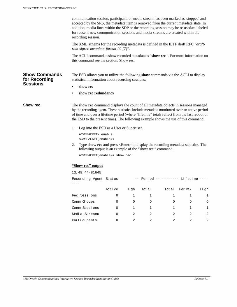
SELECTIVE CALL RECORDING/SIPREC
138 Oracle Communications Interactive Session Recorder Installation Guide Release 5.1
communication session, participant, or media stream has been marked as 'stopped' and accepted by the SRS, the metadata item is removed from the current metadata state. In addition, media lines within the SDP or the recording session may be re-used/re-labeled for reuse if new communication sessions and media streams are created within the recording session.
The XML schema for the recording metadata is defined in the IETF draft RFC “draft-ram-siprec-metadata-format-02 [7]”.
The ACLI command to show recorded metadata is “show rec ”. For more information on this command see the section, Show rec.
Show Commands for Recording Sessions
The ESD allows you to utilize the following show commands via the ACLI to display statistical information about recording sessions:
• show rec
• show rec redundancy
Show rec The show rec command displays the count of all metadata objects in sessions managed by the recording agent. These statistics include metadata monitored over an active period of time and over a lifetime period (where “lifetime” totals reflect from the last reboot of the ESD to the present time). The following example shows the use of this command.
1. Log into the ESD as a User or Superuser.
ACMEPACKET> enable
ACMEPACKET(enable)#
2. Type show rec and press <Enter> to display the recording metadata statistics. The following output is an example of the “show rec ” command.
ACMEPACKET(enable)# show rec
“Show rec” output
13:49:44-81645
Recording Agent Status -- Period -- -------- Lifetime --------
Active High Total Total PerMax High
Rec Sessions 0 1 1 1 1 1
Comm Groups 0 0 0 0 0 0
Comm Sessions 0 1 1 1 1 1
Media Streams 0 2 2 2 2 2
Participants 0 2 2 2 2 2

SELECTIVE CALL RECORDING/SIPREC
Release 5.1 Oracle Communications Interactive Session Recorder Installation Guide 139
The following table describes the metadata objects in the “show rec ” command output.
Object Description
Rec Sessions Number of recording sessions during an active period of time and over a lifetime period.
Comm Groups Number of active communication session recording groups during an active period of time and over a lifetime period.
Comm Sessions Number of active communication sessions during an active period of time and over a lifetime period.
Media Streams Number of active media streams during an active period of time and over a lifetime period.
Participants Total number of participants in session recordings during an active period of time and over a lifetime period.
Show rec redundancy The show rec redundancy command displays information for session recording server statistics when the ESD is configured for HA. These statistics include metadata monitored over an active period of time and over a lifetime period (where “lifetime” totals reflect from the last reboot of the ESD to the present time) on both the primary and redundant ESD. The following example shows the use of this command.
1. Log into the ESD as a User or Superuser.
ACMEPACKET> enable
ACMEPACKET(enable)#
2. Type show rec redundancy and press <Enter> to display the session recording server statistics for ESDs in HA mode. The following output is an example of the “show rec redundancy” command.
ACMEPACKET(enable)# show rec redundancy
Show rec redundancy output
Primary System
13:49:44-81645
Recording Agent Status -- Period -- -------- Lifetime --------
Active High Total Total PerMax High
Rec Sessions 0 1 1 1 1 1
Comm Groups 0 0 0 0 0 0
Comm Sessions 0 1 1 1 1 1
Media Streams 0 2 2 2 2 2
Participants 0 2 2 2 2 2
Redundant System
13:49:44-81646
Recording Agent Status -- Period -- -------- Lifetime --------
Active High Total Total PerMax High

SELECTIVE CALL RECORDING/SIPREC
140 Oracle Communications Interactive Session Recorder Installation Guide Release 5.1
Rec Sessions 0 1 1 1 1 1
Comm Groups 0 0 0 0 0 0
Comm Sessions 0 1 1 1 1 1
Media Streams 0 2 2 2 2 2
Participants 0 2 2 2 2 2
The following table describes the session recording server statistics in the show rec redundancy command output.
Object Description
Rec Sessions Number of recording sessions during an active period of time and over a lifetime period.
Comm Groups Number of active communication session recording groups during an active period of time and over a lifetime period.
Comm Sessions Number of active communication sessions during an active period of time and over a lifetime period.
Media Streams Number of active media streams during an active period of time and over a lifetime period.
Participants Total number of participants in session recordings during an active period of time and over a lifetime period.
Codec Negotiation
In a SIPREC environment, it is assumed that the recording ecosystem provides transcoding media servers for which media calls can be redirected to, relieving the issue of codec matching from the recording servers. However, if transcoding media servers are not provided, the responsibility for transcoding falls on the recording server or the recording client in a SIPREC environment. The ESD/SRC is required to impose some policy decisions on the codec negotiation between the three, or more, end-points. Specifically, the codec negotiation between the two participants and the recording server is subject to additional policy actions.
The SDP answer from the SRS may not agree with the media flows established in the communication session between UA-A and UA-B. If UA-A and UA-B agree to use G729, yet the SRS's answer indicates no support for G729, the SRS is then unable to interpret the media streams. The SDP offer forwarded to the called party (in this case UA-B) limits the codec choices to those supported by the SRS.
Note: The recording agent forwards the original codec offer to the SRS prior to sending the invite to the UA-B. The SRS responds with the SDP answer, indicating the codec list most desirable to the SRS. The codec list in the answer is then forwarded to UA-B. This allows three parties in a conference call to participate in the negotiation of the codecs among the supported formats only.

SELECTIVE CALL RECORDING/SIPREC
Release 5.1 Oracle Communications Interactive Session Recorder Installation Guide 141
SIPREC Call Flows
This section provides examples of call flow scenarios that can occur in a SIPREC environment. SIP recording call flow examples include:
For Selective Recording:
• Normal Call (recording required)
• Normal Call (recording not required)
• Early Media Call (recording not required)
• REFER Pass-Through Call (REFER handled by User Agent)
• REFER Call (REFER handled by ESD)
• SRS Indicates Busy in Call (recording not required)
Note: REFER is a SIP method indicating that the recipient (identified by the Request-URI) should contact a third party using the contact information provided in the request.
Selective Recording
Normal Call (recording required)
The following illustration shows a normal call using selective recording with recording required. For SDP and Metadata information in Notes 1 and 2 , see Sample SDP and Metadata.

SELECTIVE CALL RECORDING/SIPREC
142 Oracle Communications Interactive Session Recorder Installation Guide Release 5.1
I
Call Flow Description
q UA-A sends INVITE to ESD. a RTP stream initiated between ESD and UA-B.
w ESD forwards INVITE with SDP and metadata to SRS. s RTP stream initiated between ESD and SRS.
e SRS responds with OK to ESD. d UA-A sends BYE to ESD.
r ESD sends INVITE to UA-B. f ESD responds with OK to UA-A.
t UA-B responds with OK to ESD. g ESD sends BYE to ESD.
y ESD sends re-INVITE with SDP and metadata changes to SRS. h ESD responds with OK to UA-A.
u SRS responds with OK to ESD. j ESD sends BYE to UA-B.
i ESD forwards OK response to UA-A. k UA-B responds with OK to ESD.
o RTP stream initiated between UA-A and ESD. l ESD sends BYE to SRS.
; SRS responds with OK to ESD.
Sample SDP and Metadata
The following sample SDP and Metadata pertain to Notes 1 and 2 in the previous Call Flow diagram.
--[Note 1]------------------------------Content-Type: application/sdpv=0o=- 171 213 IN IP4 10.0.0.2s=-c=IN IP4 10.0.0.1t=0 0m=audio 6000 RTP/AVP 0a=rtpmap:0 PCMU/8000a=label:1
Content-Type: application/rs-metadata+xmlContent-Disposition: recording-session<?xml version='1.0' encoding='UTF-8'?><recording xmlns='urn:ietf:params:xml:ns:recording'> <dataMode>complete</dataMode> <session id="urn:uuid:79b2fcd8-5c7f-455c-783f-db334e5d57d0"> <start-time>2011-06-27T17:03:57</start-time> </session> <participant id="urn:uuid:10ac9063-76b7-40bb-4587-08ba290d7327" session="urn:uuid:79b2fcd8-5c7f-455c-783f-db334e5d57d0"> <aor>sip:[email protected]</aor> <name>sipp </name> <send>urn:uuid:07868c77-ef8e-4d6f-6dd5-a02ff53a1329</send> <start-time>2011-06-27T17:03:57</start-time> </participant> <participant id="urn:uuid:797c45f5-e765-4b12-52b0-d9be31138529" session="urn:uuid:79b2fcd8-5c7f-455c-783f-db334e5d57d0"> <aor>sip:[email protected]</aor> <name>sut </name> </participant> <stream id="urn:uuid:4a72a1ed-abb2-4d7c-5f4d-6d4c36e2d4ec" session="urn:uuid:79b2fcd8-5c7f-455c-783f-db334e5d57d0"> <mode>separate</mode> <start-time>2011-06-27T17:03:57</start-time><label>1</label> </stream></recording>
--[Note 2]------------------------------
Content-Type: application/sdpv=0o=- 171 213 IN IP4 10.0.0.2s=-c=IN IP4 10.0.0.1t=0 0

SELECTIVE CALL RECORDING/SIPREC
Release 5.1 Oracle Communications Interactive Session Recorder Installation Guide 143
m=audio 6000 RTP/AVP 0a=rtpmap:0 PCMU/8000a=label:1m=audio 6002 RTP/AVP 0a=rtpmap:0 PCMU/8000a=label:2
Content-Type: application/rs-metadata+xmlContent-Disposition: recording-session<?xml version='1.0' encoding='UTF-8'?><recording xmlns='urn:ietf:params:xml:ns:recording'> <dataMode>partial</dataMode> <session id="urn:uuid:79b2fcd8-5c7f-455c-783f-db334e5d57d0"> <start-time>2011-06-27T17:03:57</start-time> </session> <participant id="urn:uuid:797c45f5-e765-4b12-52b0-d9be31138529" session="urn:uuid:79b2fcd8-5c7f-455c-783f-db334e5d57d0"> <aor>sip:[email protected]</aor> <name>sut </name> <send>urn:uuid:4a72a1ed-abb2-4d7c-5f4d-6d4c36e2d4ec</send> <start-time>2011-06-27T17:03:58</start-time> </participant> <stream id="urn:uuid:07868c77-ef8e-4d6f-6dd5-a02ff53a1329" session="urn:uuid:79b2fcd8-5c7f-455c-783f-db334e5d57d0"> <mode>separate</mode> <start-time>2011-06-27T17:03:58</start-time><label>2</label> </stream></recording>

SELECTIVE CALL RECORDING/SIPREC
144 Oracle Communications Interactive Session Recorder Installation Guide Release 5.1
Normal Call (recording not required)
The following illustration shows a normal call using selective recording with recording optional.
Call Flow Description
q UA-A sends INVITE to ESD. i RTP stream initiated between ESD and SRS.
w ESD forwards INVITE to UA-B. o UA-A sends BYE to ESD.
e UA-B responds with OK to ESD. a ESD responds with OK to UA-A.
r ESD forwards OK response to UA-A. s ESD sends BYE to UA-B.
t ESD sends INVITE with SDP and metadata to SRS. d UA-B responds with OK to ESD.
y SRS responds with OK to ESD. f ESD sends BYE to SRS.
u RTP stream initiated between UA-A, ESD, and UA-B. g SRS responds with OK to ESD.

SELECTIVE CALL RECORDING/SIPREC
Release 5.1 Oracle Communications Interactive Session Recorder Installation Guide 145
Early Media Call (recording not required)
The following illustration shows an early media call using selective recording with recording optional.
Call Flow Description
q UA-A sends INVITE to ESD. a UA-B responds with OK to ESD.
w ESD forwards INVITE to UA-B. s ESD forwards OK to UA-A.
e UA-B sends 180 and SDP to ESD. d ESD sends re-INVITE with SDP and metadata changes to SRS.
r ESD sends INVITE with SDP and metadata to SRS. f SRS responds with OK to ESD.
t SRS responds with OK to ESD. g UA-A sends BYE to ESD.
y ESD sends 180 with SDP to UA-A. h ESD responds with OK to UA-A.
u RTP stream initiated between ESD and UA-A. j ESD sends BYE to UA-B.
i RTP stream initiated between ESD and UA-B. k UA-B responds with OK to ESD.
o RTP stream initiated between ESD and SRS. l ESD sends BYE to SRS.
; SRS responds with OK to ESD.

SELECTIVE CALL RECORDING/SIPREC
146 Oracle Communications Interactive Session Recorder Installation Guide Release 5.1
REFER Pass-Through Call (REFER handled by User Agent)
The following illustration shows a REFER pass-through call using selective recording and the User Agent (UA) handling the REFER on the call. Recording is required in this call flow.
Call Flow Description
q UA-A sends INVITE to ESD. l UA-C responds with OK to ESD.
w ESD forwards INVITE with SDP Offer and metadata to SRS. ; ESD forwards OK response to UA-B.
e SRS responds with OK to ESD. 20 ESD sends NOTIFY with OK reponse to UA-A.
r ESD sends INVITE to UA-B. 21 ESD sends re-INVITE to SRS with new SDP and metadata, adds participant C, stops participant A .
t UA-B responds with OK to ESD. 22 SRS responds with OK to ESD.
y ESD sends re-INVITE with SDP and metadata changes to SRS. 23 UA-A sends BYE to ESD.
u SRS responds with OK to ESD. 24 ESD responds with OK to UA-A.
i ESD forwards OK response to UA-A. 25 ESD responds with OK to UA-A.
o RTP stream initiated between UA-A and ESD. 26 RTP stream initiated between ESD and UA-B.

SELECTIVE CALL RECORDING/SIPREC
Release 5.1 Oracle Communications Interactive Session Recorder Installation Guide 147
REFER Call (REFER handled by ESD)
The following illustration shows a call using selective recording and the Session Border Controller ESD) handling the REFER on the call. Recording is required in this call flow.
a RTP stream initiated between ESD and UA-B. 27 RTP stream initiated between ESD and UA-C.
s RTP stream initiated between ESD and SRS. 28 RTP stream initiated between ESD and SRS.
d UA-A sends REFER-TO: C to ESD. 29 UA-C sends BYE to ESD.
f ESD forwards REFER-TO: C to UA-B. 30 ESD responds with OK to UA-C.
g UA-B responds with 202 ACCEPTED to ESD. 31 ESD sends BYE to UA-B.
h ESD forwards 202 ACCEPTED to UA-A. 32 UA-B responds with OK to ESD.
j UA-B sends INVITE TO: C to ESD. 33 ESD sends BYE to SRS
k ESD sends INVITE to UA-C. 34 SRS responds with OK to ESD.
Call Flow Description

Call Flow Description
q UA-A sends INVITE to ESD. j ESD sends NOTIFY with OK response to UA-A.
w ESD forwards INVITE with SDP Offer and metadata to SRS. k UA-A sends BYE to ESD.
e SRS responds with OK to ESD. l ESD responds with OK to UA-A.
r ESD sends INVITE to UA-B. ; ESD sends re-INVITE to UA-B.
t UA-B responds with OK to ESD. 20 UA-B responds with OK to ESD.
y ESD sends re-INVITE with SDP and metadata changes to SRS. 21 ESD sends re-INVITE to SRS with new SDP and metadata.
u SRS responds with OK to ESD. 22 SRS responds with OK to ESD.
i ESD forwards OK response to UA-A. 23 RTP stream initiated between ESD and UA-B.
o RTP stream initiated between UA-A and ESD. 24 RTP stream initiated between ESD and UA-C.
a RTP stream initiated between ESD and UA-B. 25 RTP stream initiated between ESD and SRS.
s RTP stream initiated between ESD and SRS. 26 UA-C sends BYE to ESD.
d UA-A sends REFER-TO: C to ESD. 27 ESD responds with OK to UA-C.
f ESD responds with 202 ACCEPTED to UA-A. 28 ESD sends BYE to UA-B.
g ESD sends INVITE to UA-C. 29 UA-B responds with OK to ESD.
h UA-C responds with OK to ESD. 30 ESD sends BYE to SRS.
31 SRS responds with OK to ESD.
SELECTIVE CALL RECORDING/SIPREC
148 Oracle Communications Interactive Session Recorder Installation Guide Release 5.1

SELECTIVE CALL RECORDING/SIPREC
Release 5.1 Oracle Communications Interactive Session Recorder Installation Guide 149
SRS Indicates Busy in Call (recording not required)
The following illustration shows the Session Recording Server (SRS) is BUSY for a call session. Recording is not required in this call flow.
Call Flow Description
q UA-A sends INVITE to ESD. o ESD sends INVITE to SRS2 with SDP and metadata.
w ESD forwards INVITE to UA-B. a SRS2 responds with OK to ESD.
e UA-B responds with OK to ESD. s RTP stream initiated between ESD and SRS2.
r ESD forwards OK response to UA-A. d UA-A sends BYE to ESD.
t ESD sends INVITE to SRS1 with SDP and metadata. f ESD responds with OK to UA-A.
y SRS1 responds to ESD with 436 BUSY HERE. g ESD sends BYE to UA-B.
u RTP stream initiated between UA-A and ESD. h UA-B responds with OK to ESD.
i RTP stream initiated between ESD and UA-B. j ESD sends BYE to SRS2.
k SRS2 responds with OK to ESD.

SELECTIVE CALL RECORDING/SIPREC
150 Oracle Communications Interactive Session Recorder Installation Guide Release 5.1

Release 5.1 Oracle Communications Interactive Session Recorder Installation Guide 151
G Installing the Remote Archiver Webservice
Introduction
This chapter provides information about importing and running the ISR’s Remote Archival Webservice.
Remote Archival Webservice Platform Requirements
The Remote Archival Webservice currently runs exclusively as a VM on the vSphere Hypervisor platform (formerly known as ESXi), the free edition of vSphere’s bare-metal virtualization product.
The vSphere Hypervisor is required for operation of the ISR and installation instructions can be found in the Interactive Session Recorder Installation Guide.
The Remote Archival Webservice’s VM is built with a default configuration that expects 1 virtual CPU (vCPU), 2GB of RAM, and 12GB of disk space available to the Remote Archival Webservice guest OS. These initial configuration settings may be adjusted for specific deployment needs.
Deploying the Remote Archival Webservice VM
To deploy the Remote Archival Webservice’s VM, first import the VM and then assign it an IP address.
To import the VM:
1. Open VMWare vSphere Client.
2. Connect to your vSphere Host by checking Install this certificate and do not display any security warnings for <ip_address>. Click Ignore.
3. Click File > Deploy OVF Template....
4. Browse to the unzipped “ISR Remote Archival Webservice <version #> <build #>.zip” directory, select RemoteArchivalWebservice.ovf and click Next.
5. Click Next at both the summary and VM name and location.
6. Select Thin provisioned format and click Next.
7. Verify that the “VM Network” and “VM Local” Source and Destination Networks are listed, review the summary, and click Finish.
8. Close the OVF deployment window.
9. Click on the VM named Remote Archival (or rWebservice in older versions) in the left panel and hit the start (play) button.
To assign an IP address to the VM:
1. Click the Console tab and place your cursor in the main panel.
Note: Your mouse is confined to the console pane. Hit Alt+Ctrl to release.

INSTALLING THE REMOTE ARCHIVER WEBSERVICE
152 Oracle Communications Interactive Session Recorder Installation Guide Release 5.1
2. Log in using username root and the root password.
3. Execute the configCis.sh script.
4. Select one of the following:
• s <Enter>—Show the current configuration
• q <Enter>—Quit the application
• m <Enter>—Modifies the current CIS configuration. The following fields appear:
• Enter host IP: [<current IP>]
– The Eth0 interface IPv4 address of the CIS host
• Enter prefix: [16]
– The routing prefix, e.g. 192.168.1.1/16
• Enter gateway IP: [<current_gateway_ip>]
– The IPv4 address of the network gateway or router.
• Enter DNS1 IP: [<current_dns1_ip or none>]
– The IPv4 address of the first DNS, which may be skipped (set to none) and ignored
• Enter DNS2 IP: [<current_dns2_ip or none>]
– The IPv4 address of the second DNS, which may be skipped (set to none) and ignored
Note: To skip to the next field, hit <Enter>.

Release 5.1 Oracle Communications Interactive Session Recorder Installation Guide 153
H Configuring An NFS Share For Archival
Introduction
This chapter provides information about configuring a Network File System (NFS) share for archival.
To configure archival to an NFS share:
1. From the RSS OS-E CLI, configure the NFS client via the services > data-locations > nfs object.
NN-ISR>config services data-locations
config data-locations>config nfs <nfsserverhostname>
Creating 'nfs nfsserverhostname'
config nfs nfsserverhostname>set server <nfs server ip>
config nfs nfsserverhostname>set share </full/share/path>
config nfs nfsserverhostname>exit
Do you want to commit your changes before you exit (y or n)? y
Do you want to update the startup configuration (y or n)? y
NN-ISR>
2. From the RSS OS-E CLI, use the show nfs command to verify that the NFS data location has been created.
config vrrp>show nfs
mount-point server share
----------- ------ -----
/mnt/nfsserverhostname 1.2.3.4 /full/share/path
3. From the RSS Linux shell, verify that the share is accessible.
NN-ISR>shell
nn-isr app_slot_1 # cd /mnt/nfsserverhostname
nn-isr nfsserverhostname # ls -l
total 8
-rw-r--r-- 1 nobody nobody 0 Dec 18 16:39 file1.txt
-rw-r--r-- 1 nobody nobody 7 Dec 18 16:35 file2.txt
-rw-r--r-- 1 root root 35 Dec 18 11:45 this.is.on.an.nfs.drive.txt
The network share is now accessible and reconnects upon reboot.
4. Link the new mounted path to the default Archived Recordings Location.
ln -s /mnt/<nfsservername> /cxc_common/ISR/ArchivedRecordings
5. From the RSS Linux shell, verify that the RSS jboss user has write permissions on the NFS share.
• Change the user via the su jboss command.
• Add a file on the share.
touch /cxc_common/ISR/ArchivedRecordings/foo.txt
• Verify that the file exists
ls -l/cxc_common/ISR/ArchivedRecordings/foo.txt

CONFIGURING AN NFS SHARE FOR ARCHIVAL
154 Oracle Communications Interactive Session Recorder Installation Guide Release 5.1
6. From the RSS Linux shell, using the /etc/init.d/tomcat restart command, restart Tomcat. Since the Archived Location was not available as a resource to the application server responsible for serving recordings previously, this is necessary.
7. From the ISR Dashboard, add the new Archival Location.
• Click the Admin tab.
• Click the Manage Sites link.
• Click on the displayed Site.
• Click on the Locations icon.
• Click the New Location link.
• name—Enter a specific name for the Location.
• Recordings Directory—Set the recordings directory path to /cxc_common/ISR/ArchivedRecordings.
• URL—Set the URL serving recordings in the directory (this is likely to be http://<RSS IP>/ArchivedRecording).
• IP Address—Specify the RSS IP address for conversion to play recordings using certain codecs.
• Click Create.
8. From the ISR Dashboard, configure Archival to the Location.
• Click the Admin tab.
• Click the Manage Sites link.
• Click on the displayed Site.
• Click on the Archivers icon.

CONFIGURING AN NFS SHARE FOR ARCHIVAL
Release 5.1 Oracle Communications Interactive Session Recorder Installation Guide 155
• Click the New Archiver link.
• IP Address—Enter the RSS IP address.
• Source Location—Set to <RSS name> (<RSS IP>) Primary.
• Destination Location—Set to the name you gave the Location.
• Click Create.
For more information on advanced settings while configuring a new Archiver, see “Managing Archivers” in the Oracle Communications Interactive Session Recorder Administrator Guide.
9. From the ISR Dashboard, verify that Archival is configured properly.
• Click on the Recordings tab.
• Click on a recording to display the details.
• Click the File Location tab and verify that the recording was archived in the Archival Remarks field.
Note: By default, the Archival process runs every two minutes and you must wait for it to run at its scheduled time.

CONFIGURING AN NFS SHARE FOR ARCHIVAL
156 Oracle Communications Interactive Session Recorder Installation Guide Release 5.1


![ROR [20791]](https://static.documents.pub/doc/80x56/563db9ca550346aa9a9feea2/ror-20791.jpg)


