TABLE OF CONTENTS 1. Executive Summary ........................................................................................................................................... 1
2. Test Overview .................................................................................................................................................... 2
Scope of Work ....................................................................................................................................................... 2
Test Boundaries ..................................................................................................................................................... 2
Test Responsibilities .............................................................................................................................................. 3
Test Preparations................................................................................................................................................... 4
Test Schedule ......................................................................................................................................................... 4
Test Conditions ...................................................................................................................................................... 4
Test Instruments and Calibration .......................................................................................................................... 6
5. Result Calculation .............................................................................................................................................. 9
Result Summary ..................................................................................................................................................... 9
Appendix A: Far‐Field Measurement Locations ........................................................................................................ A
Appendix B: Test Deviation Form .............................................................................................................................. B
Appendix C: CleanAir Noise Testing Capability ......................................................................................................... C
Docket No. EL17-042 Attachment 3 Page 3 of 20
Otter Tail Power Company Otter Tail No. A‐8805
Otter Tail Astoria Station Revision 1
Far‐Field Noise Emissions Test Plan Page iv
LIST OF TABLES Table 2‐1: Noise Emissions Requirements ................................................................................................................ 3
Table 2‐2: Test Preparation Activities ....................................................................................................................... 4
Table 2‐3: Test Daily Schedule of Activities ............................................................................................................... 4
Table 3‐1: Test Instrumentation ................................................................................................................................ 6
Docket No. EL17-042 Attachment 3 Page 4 of 20
Otter Tail Power Company Otter Tail No. A‐8805
Otter Tail Astoria Station Revision 1
Far‐Field Noise Emissions Test Plan Page 1
1. EXECUTIVE SUMMARY Otter Tail Power Company (Otter Tail) contracted with CleanAir Engineering (CleanAir) to write a site specific test plan, execute testing, and calculate results for far‐field noise emissions testing of a Mitsubishi Hitachi Power Systems (MHPS) 501GAC gas turbine at the Otter Tail Astoria Power Station located in Astoria, South Dakota. This document describes the process to execute the far‐field noise testing.
The objective of the testing is to ensure that far‐field noise from Astoria Station meets the limits set forth by the South Dakota Public Utilities Commission. The far field noise testing will be conducted under the direction of CleanAir’s technical leader David Wheeler.
This test plan documents the schedule of the testing activities, the plant operating conditions under which the tests are to be performed, specifies the instrumentation to be used for the tests, and the evaluation of the test results. Any deviations from this test plan shall be mutually agreed upon in writing by all the testing parties. A test deviation form is included in Appendix B, which shall be used to record deviations that occur just prior to or during the testing.
CleanAir performance group personnel routinely provide noise testing services for power plant components. We have conducted dozens of tests at facilities both in the US and Internationally. We work with our clients to develop test programs and evaluations to meet the specific objectives of each project. All noise test programs developed by CleanAir are informed by the guidance of ANSI S1,13, ASME PTC 36 and ANSI B133.8. Additional information about CleanAir’s noise testing capabilities is included in Appendix C.
End of Section
Docket No. EL17-042 Attachment 3 Page 5 of 20
Otter Tail Power Company Otter Tail No. A‐8805
Otter Tail Astoria Station Revision 1
Far‐Field Noise Emissions Test Plan Page 2
2. TEST OVERVIEW
Scope of Work
Otter Tail Power Company (Otter Tail) contracted with CleanAir Engineering (CleanAir) to write a site‐specific test plan, execute testing, and calculate results for far‐field noise emissions testing at the Otter Tail Astoria Power Station located in Astoria, South Dakota. This document describes the process to execute the far‐field noise testing.
The objective of the testing is to ensure that far‐field noise from Astoria Station meets the limits set forth by the South Dakota Public Utilities Commission. The far field noise testing will be conducted under the direction of CleanAir’s technical leader David Wheeler.
Plant Description
The Otter Tail Astoria Station is a 245‐megawatt simple cycle facility which consists of one MHPS 501GAC gas turbine generator and supporting equipment which is fired solely on natural gas. The gas turbine is equipped with an evaporative cooler to increase power output when ambient conditions allow.
Test Boundaries
Far‐field testing will consist of measurements at two points, as shown in Exhibit 13‐3 in Appendix A:
ML1, approximately 3800 feet southwest of the facility power block.
ML2, approximately 6000 feet east‐southeast of the facility power block.
Permit Requirements
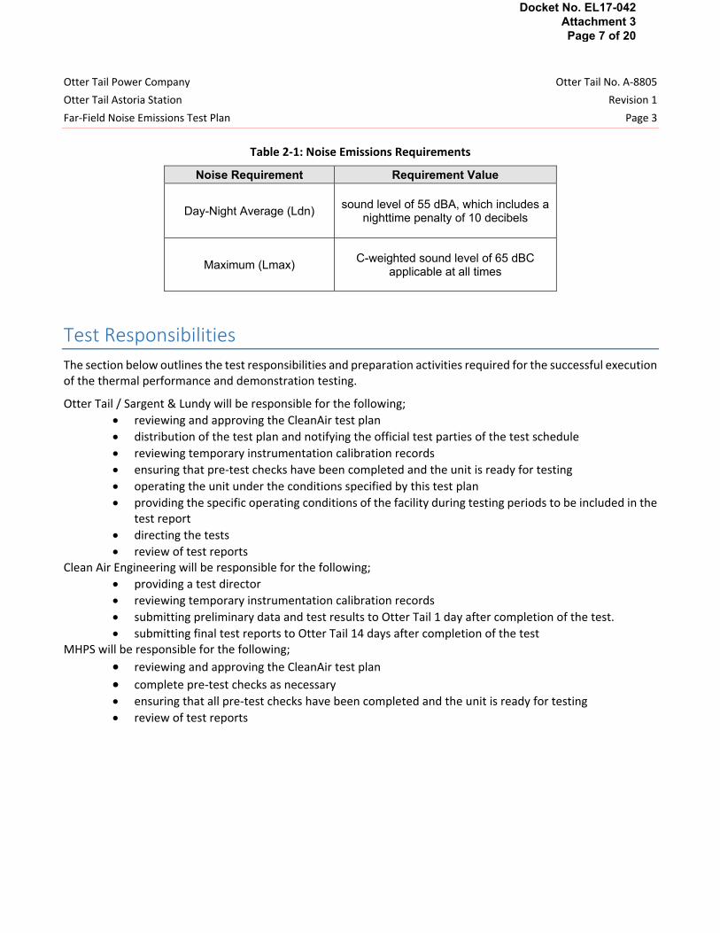
Table 2‐1 lists the permitted sound emissions levels according to South Dakota Public Utilities Commission Stipulation EL17‐042, signed July 12, 2018. All noise test programs developed by CleanAir are informed by the guidance of ANSI S1.13, ASME PTC 36 and ANSI B133.8. No test tolerance will be applied to the measured sound levels for comparison with the limits set forth by the South Dakota Public Utilities Commission.
Docket No. EL17-042 Attachment 3 Page 6 of 20
Otter Tail Power Company Otter Tail No. A‐8805
Otter Tail Astoria Station Revision 1
Far‐Field Noise Emissions Test Plan Page 3
Table 2‐1: Noise Emissions Requirements
Noise Requirement Requirement Value
Day-Night Average (Ldn) sound level of 55 dBA, which includes a
nighttime penalty of 10 decibels
Maximum (Lmax) C-weighted sound level of 65 dBC
applicable at all times
Test Responsibilities
The section below outlines the test responsibilities and preparation activities required for the successful execution of the thermal performance and demonstration testing.
Otter Tail / Sargent & Lundy will be responsible for the following;
reviewing and approving the CleanAir test plan
distribution of the test plan and notifying the official test parties of the test schedule
reviewing temporary instrumentation calibration records
ensuring that pre‐test checks have been completed and the unit is ready for testing
operating the unit under the conditions specified by this test plan
providing the specific operating conditions of the facility during testing periods to be included in thetest report
directing the tests
review of test reportsClean Air Engineering will be responsible for the following;
providing a test director
reviewing temporary instrumentation calibration records
submitting preliminary data and test results to Otter Tail 1 day after completion of the test.
submitting final test reports to Otter Tail 14 days after completion of the testMHPS will be responsible for the following;
reviewing and approving the CleanAir test plan
complete pre‐test checks as necessary
ensuring that all pre‐test checks have been completed and the unit is ready for testing
review of test reports
Docket No. EL17-042 Attachment 3 Page 7 of 20
Otter Tail Power Company Otter Tail No. A‐8805
Otter Tail Astoria Station Revision 1
Far‐Field Noise Emissions Test Plan Page 4
Test Preparations
A summary of test preparation items to be performed by Otter Tail prior to arrival of the test parties is shown in Table 2‐2.
Table 2‐2: Test Preparation Activities Item Subject Prior to Arrival of Test Parties
1 Site Access All requirements for site access for vehicles and personnel, including safety training, PPE requirements, drug tests, background checks, covid-19 checks etc. should be arranged with the test parties.
2 Test Party Notification Notify the test parties of the test schedule so that, if desired, each party can have a representative present for the testing activities.
Test Schedule
The noise emissions testing has not been scheduled as of the issuance of this test plan. The anticipated daily schedule of events for the testing is shown in table 2‐3. The unit will need to be offline to perform background sound measurements.
Table 2‐3: Test Daily Schedule of Activities
Test Day1 – Time of Day2 List of Activities
1 – 07:00 ML1 daytime far-field sound measurements with the unit operating at base load.
1 – 10:00 ML2 daytime far-field sound measurements with the unit operating at base load. If wind conditions become unfavorable at this time, measurement period to be moved to early morning on site day 2.
1 – 22:00 ML1 nighttime far-field sound measurements with the unit operating at base load.
2 – 01:00 ML2 nighttime far-field sound measurements with the unit operating at base load.
2 – 07:00 Alternate measurement period for daytime far-field sound measurements at ML2.
1. Test dates to be determined based on plant commissioning milestones and schedules. 2.Actual test time will be dependent on plant operation, wind, and weather conditions.
Test Conditions For the operating sound level measurements, the unit should be operated at base load with all equipment in a normal operating configuration. All access doors and hatches on sound mitigating enclosures should be closed. Testing should be conducted when construction, heavy machinery operation, maintenance and repair activities, road traffic, and any other extraneous activities that produce excess noise are at a minimum.
Docket No. EL17-042 Attachment 3 Page 8 of 20
Otter Tail Power Company Otter Tail No. A‐8805
Otter Tail Astoria Station Revision 1
Far‐Field Noise Emissions Test Plan Page 5
Testing shall be conducted under fair weather conditions without any precipitation occurring and no standing water or snow present on the ground. The average wind speed during measurement periods should not exceed 7 mph.
Far‐field measurements will be recorded with the sound meter mounted on a tripod at an elevation of five feet above grade level at the two designated measurement locations. Measurement duration will be such that the sound levels at each location can be accurately captured with a minimum measurement time of two hours, providing sufficient data for accurate characterization of average noise levels from a constant source. A test log will be maintained during the test to record any occurrences affecting the test, the time of the occurrences, and the observed effect. These occurrences will include nearby vehicular traffic, wildlife such as birds chirping, and farm machinery activity.
End of Section
Docket No. EL17-042 Attachment 3 Page 9 of 20
Otter Tail Power Company Otter Tail No. A‐8805
Otter Tail Astoria Station Revision 1
Far‐Field Noise Emissions Test Plan Page 6
3. METHODOLOGY
Test Instruments and Calibration
The temporary test instrumentation that will be supplied by CleanAir for the testing shall have calibrations traceable to the National Institute of Standards and Technology (NIST), nationally recognized standards, or physical constants. The calibration records for the performance instruments will be furnished to the testing parties 14 days prior to the testing.
A summary of the test instruments that will be used for the noise emissions tests are found in Table 3‐1.
Table 3‐1: Test Instrumentation
No. Parameter Instrument Supplier
1 Ambient Air Temperature One RTD CleanAir
2 Ambient Wet Bulb Temperature One RTD installed in a mechanically
aspirated psychrometer CleanAir
3 Barometric Pressure One hand‐held barometer CleanAir
Temperature measurements will be made with precision RTDs with a calibrated accuracy of 0.1°F. Ambient dry bulb and wet bulb temperatures will each be measured with a precision RTD placed in a mechanically aspirated psychrometer mounted on a tripod such that it is five feet above grade level. The tripod will be placed at a location where power is available to power the instruments and the true ambient conditions can be measured and not influenced by any operating plant equipment. Temperature instrumentation will have been calibrated within one year of the test date.
Wind speed will be measured with an RM Young wind speed station mounted in an unobstructed location near the ambient temperature instrumentation. The wind speed station will be calibrated within one year of the test date and have a calibrated accuracy of 1% of reading. A small hand‐held anemometer will also be used to check local wind speed at the measurement points.
Barometric pressure will be measured with a hand‐held barometer calibrated within one year of the test date with a calibrated accuracy of 0.05 psia.
Sound pressure levels will be recorded with a B&K 2250L sound level analyzer. The sound analyzer will have been calibrated within one year of the test date and will undergo a field calibration with a calibrated field calibrator before and after each measurement sequence. The sound level analyzer meets or exceeds all the requirements for an ANSI Type I sound meter. The sound level meter will be equipped with a random incidence microphone. Readings will be recorded with the meter mounted on a tripod with no obstructions between the meter and sound source and free from the influence of reflective surfaces.
Docket No. EL17-042 Attachment 3 Page 10 of 20
Otter Tail Power Company Otter Tail No. A‐8805
Otter Tail Astoria Station Revision 1
Far‐Field Noise Emissions Test Plan Page 7
A test log will be maintained during the test to record any occurrences affecting the test, the time of the occurrences, and the observed effect. These occurrences will include nearby vehicular traffic, wildlife such as birds chirping, and farm machinery activity.
Due to the steady sound pressure levels produced by a power plant running at steady state, the noise will not fluctuate or exhibit “noise events” during the day or night testing, and a full 24 hour test cycle will not be necessary to accurately quantify the day‐night average. Testing will consist of a two‐hour daytime measurement and a two‐hour nighttime measurement at each of the two far‐field test locations referenced in Exhibit 13‐3 in Appendix A. A 10 dB penalty shall be applied to the nighttime test measurements.
End of Section
Docket No. EL17-042 Attachment 3 Page 11 of 20
Otter Tail Power Company Otter Tail No. A‐8805
Otter Tail Astoria Station Revision 1
Far‐Field Noise Emissions Test Plan Page 8
4. CALCULATION METHODOLOGY
Test Tolerances
No test tolerance will be applied to the measured sound levels for comparison with guarantee values.
Far-field Sound
Far‐field sound will be measured at the two designated points, ML1 and ML2, during both daytime and nighttime hours. Sound levels will be recorded with an integrating and averaging sound level analyzer for a minimum time period of 5 minutes. The overall A‐weighted equivalent sound pressure level (LAeq), maximum C‐weighted sound level (Lmax), and one‐third octave band sound levels will be recorded and stored for each measurement period. The day‐night average sound level will be calculated as:
𝐿 10 log15 ∗ 10 . 9 ∗ 10 .
24
where:
𝐿 = the day‐night average overall A‐weighted sound pressure level (SPL), dBA 𝐿 = the recorded daytime overall A‐weighted SPL, dBA 𝐿 = the recorded nighttime overall A‐weighted SPL, dBA
End of Section
Docket No. EL17-042 Attachment 3 Page 12 of 20
Otter Tail Power Company Otter Tail No. A‐8805
Otter Tail Astoria Station Revision 1
Far‐Field Noise Emissions Test Plan Page 9
5. RESULT CALCULATION
Result Summary
The measured and calculated sound levels from the previous section will be compared with the appropriate permit requirements.
The far‐field sound levels will meet the permit requirements if the following is true;
CleanAir will generate a summary test report that will contain the data used for the calculations and the results of the far‐field noise testing. A preliminary summary test report will be issued to Otter Tail after the completion of testing before CleanAir demobilizes from site.
The official far‐field noise test report containing all of the data for the test runs and the calculation methodology, and results will be sent to Otter Tail within 14 days after completion of the testing.
The format of the final test report will contain the following sections:
Summary including comparison of the Ldn and Lmax to the noise permit requirements
test description including test locations, time, test conditions, and extraneous noise incidence log
calculation and results
test equipment details
names of all test participants and witnesses
any deviations from this test procedure that may significantly impact the intent of the noise testing
appendices
End of Section
Docket No. EL17-042 Attachment 3 Page 13 of 20
Otter Tail Power Company Otter Tail No. A‐8805
Otter Tail Astoria Station Revision 1
Far‐Field Noise Emissions Test Plan Page A‐1
APPENDIX A: FAR-FIELD MEASUREMENT LOCATIONS
Docket No. EL17-042 Attachment 3 Page 14 of 20
27 October 5, 2017
Exhibit 13-3. Noise Monitoring Locations
Otter Tail Power Company Otter Tail Astoria Station Noise Emissions Test Plan
Otter Tail No. A-8805 Revision 1
A-2
Docket No. EL17-042 Attachment 3 Page 15 of 20
LEGEND
~ Noise Monitoring ~ Locations
t:J OTP Property
♦ Noise Sources
I 0
I I Feet
I 2,200
CS> Ori'ERT-=Al= L POWER COMPANY
Otter Tail Power Company Otter Tail No. A‐8805
Otter Tail Astoria Station Revision 1
Far‐Field Noise Emissions Test Plan Page B‐1
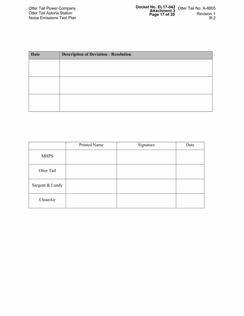
APPENDIX B: TEST DEVIATION FORM
Docket No. EL17-042 Attachment 3 Page 16 of 20
Date Description of Deviation - Resolution
Printed Name Signature Date
MHPS
Otter Tail
Sargent & Lundy
CleanAir
Otter Tail Power Company Otter Tail Astoria Station Noise Emissions Test Plan
CleanAir performance group personnel routinely provide noise testing services for power plant components. We have conducted dozens of tests at facilities both in the US and Internationally. We work with our clients to develop test programs and evaluations to meet the specific objectives of each project. All noise test programs developed by CleanAir are informed by the guidance of ANSI S1,13, ASME PTC 36 and ANSI B133.8.
CleanAir uses a B&K 2250L (or equivalent) Sound Level Meter and a B&K 4231(or equivalent) Acoustical Calibrator for the purpose of sound pressure measurements. The B&K 2250L is an ANSI Type I meter that reports sound pressure in octave bands as well as standard A and C weightings. Additionally, CleanAir is currently one of only two companies licensed by the Cooling Technology Institute (CTI) for sound testing of cooling towers.
All noise testing is conducted under the leadership of CleanAir’s technical leader, Mr. David Wheeler.
Mr. Wheeler has designed and conducted hundreds of power plant tests in his almost 40 years in the industry. During this time, Mr. Wheeler has successfully collected temperature, pressure, flow, power and sound data in very challenging environments. With so many years of experience, and intimate knowledge of many industry test codes, Mr. Wheeler’s expertise is focused on designing test programs and evaluations to meet the specific objective of each project: balancing accuracy requirements with operational, instrument and time limitations to offer practical and effective testing solutions.
Mr. Wheeler is a registered Professional Engineer in the State of Tennessee, Registration Number 016335.
He has an M.S., in Environmental Engineering, and B.S. in Chemical Engineering from the University of
Tennessee.
For most of his career Mr. Wheeler has actively participated in a variety of industry test code committees. He is a currently a member of the following test code committees: CTI ATC-128 Sound CTI ATC-105 Water Cooling Towers CTI ATC-107 Air Cooled Condensers ASME PTC 23 Atmospheric cooling equipment ASME PTC 30.1 Air Cooled Condenser ASME PTC 6 Steam Turbines
Recent projects completed under Mr. Wheeler’s direction for far field noise testing include:
Alliant Riverside II Station, Beloit, WI -CleanAir performed far-field noise surveys to illustrate compliance with local ordinances and contractual guarantees. Background and operating sound levels were measured at two locations in the middle of the night. A minimum of two, two-minute measurements were recorded at each location to ensure consistency results and accurate characterization of environmental noise.
Architect of the Capital Building, Washington DC – CleanAir performed a comprehensive far field noise survey at the boundaries with neighboring residential areas. Measurements were made at five locations
Otter Tail Power Company Otter Tail Astoria Station Noise Emissions Test Plan
around the plant property and included two different sets of daytime and nighttime measurements. The test results were compared to specific Washington, DC municipal codes provided by the client.
Bluegrass Station, LaGrange, KY -CleanAir is performing pre and post upgrade far field noise testing to ensure that noise pollution is not negatively impacted by the on-going plant upgrade. Pre-upgrade testing has been completed with four measurement points recorded for a two-minute duration at an elevation of 5 feet above grade level at each location. Both ambient and operating sound levels were recorded.
Additionally, Mr. Wheeler has supervised numerous near-field testing projects focused on demonstrating compliance with contractual guarantees for near-field worker noise exposure.
A few recent near field projects include: Stanton Energy Reliability Center, Stanton, CA MCRD CHP Plant, Parris Island, SC Mount Vernon Cogen Plant, Mount Vernon, IN Sewaren Generating Station, Sewaren, NJ
Otter Tail Power Company Otter Tail Astoria Station Noise Emissions Test Plan