This technology enables the use o renewable energy rom the sun. There are twotypes o solar energy:b Thermal energy captured through an exchange between circulating fuid exposedto the sun and a load circuit (accumulation tank or heat pump).b Photovoltaic energy, which uses the principle o the photovoltaic cell discovered byEdmond Becquerel in 1839 to produce electrical power.It is particularly bene cial to use solar radiation reaching the earth since:b This radiation remains stable (to within 10%) on average rom one year to the next;b At ground level, it supplies an average o 1000 Wh/m² per day although thisdepends on the ollowing principal criteria:v The latitudev The angle o the sur ace and the direction acedv The degree o pollutionv The time o yearv The thickness o the cloud layerv The time o dayv The shadeThis radiation varies rom 870 Wh/m² per day in the North o France to 1890 Wh/m²per day in Corsica (and up to 3125 Wh/m² per day in the Sahara).
.2 Environmental beneftsBy using solar energy, it is possible to reduce consumption o “ ossil” uels which arethe likely cause o global warming and atmospheric pollution.This contributes to sustainable development and is also in keeping with the policieso the European Council, which passed a decree in March 2007 setting the ollowingtargets to be met by 2020:b Reduction o greenhouse emissions by 20%b Reduction o energy consumption by 20%b 20% renewable energy as a proportion o total energy consumption
P - Photovoltaic installations 2 Background and technology
2. The photovoltaic e ect
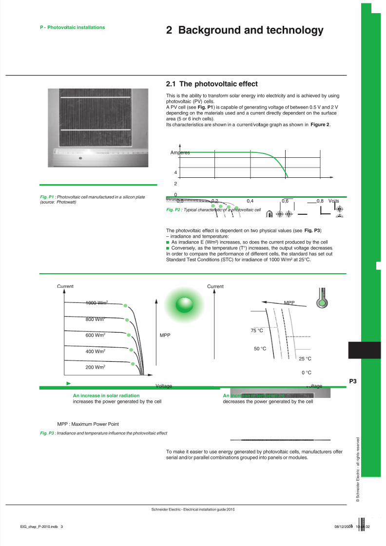
This is the ability to trans orm solar energy into electricity and is achieved by usingphotovoltaic (PV) cells.A PV cell (see Fig. P ) is capable o generating voltage o between 0.5 V and 2 Vdepending on the materials used and a current directly dependent on the sur acearea (5 or 6 inch cells).Its characteristics are shown in a current/voltage graph as shown in Figure 2 .
Fig. P1 : Photovoltaic cell manu actured in a silicon plate (source: Photowatt)
The photovoltaic e ect is dependent on two physical values (see Fig. P3 )– irradiance and temperature:b As irradiance E (Wm²) increases, so does the current produced by the cellb Conversely, as the temperature (T°) increases, the output voltage decreases.In order to compare the per ormance o di erent cells, the standard has set outStandard Test Conditions (STC) or irradiance o 1000 W/m² at 25°C.
Fig. P2 : Typical characteristic o a photovoltaic cell
0
2
4
0,0 0,2 0,4 0,6 0,8 Volts
Amperes
To make it easier to use energy generated by photovoltaic cells, manu acturers o erserial and/or parallel combinations grouped into panels or modules.
Voltage
Current
1000 Wm 2
800 Wm 2
600 Wm 2
400 Wm 2
200 Wm 2
MPP
MPP
An increase in solar radiationincreases the power generated by the cell
MPP : Maximum Power Point
Voltage
Current
75 °C
An increase in temperaturedecreases the power generated by the cell
50 °C
25 °C
0 °C
Fig. P3 : Irradiance and temperature in uence the photovoltaic e ect
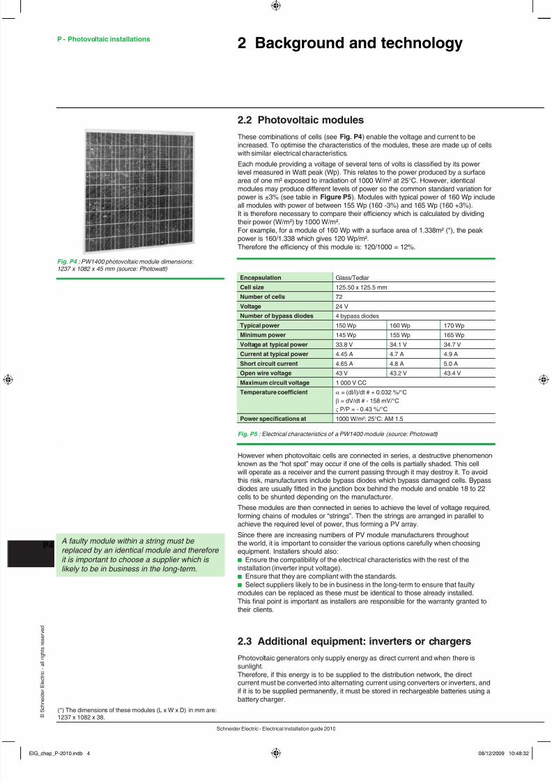
These combinations o cells (see Fig. P4 ) enable the voltage and current to beincreased. To optimise the characteristics o the modules, these are made up o cellswith similar electrical characteristics.Each module providing a voltage o several tens o volts is classi ed by its powerlevel measured in Watt peak (Wp). This relates to the power produced by a sur acearea o one m² exposed to irradiation o 1000 W/m² at 25°C. However, identicalmodules may produce di erent levels o power so the common standard variation orpower is ±3% (see table in Figure P5 ). Modules with typical power o 160 Wp includeall modules with power o between 155 Wp (160 -3%) and 165 Wp (160 +3%).It is there ore necessary to compare their e ciency which is calculated by dividingtheir power (W/m²) by 1000 W/m².For example, or a module o 160 Wp with a sur ace area o 1.338m² (*), the peakpower is 160/1.338 which gives 120 Wp/m².There ore the e ciency o this module is: 120/1000 = 12%.
Fig. P4 : PW1400 photovoltaic module dimensions: 1237 x 1082 x 45 mm (source: Photowatt)
(*) The dimensions o these modules (L x W x D) in mm are:1237 x 1082 x 38.
Encapsulation Glass/TedlarCell size 125.50 x 125.5 mmNumber o cells 72Voltage 24 VNumber o bypass diodes 4 bypass diodesTypical power 150 Wp 160 Wp 170 WpMinimum power 145 Wp 155 Wp 165 WpVoltage at typical power 33.8 V 34.1 V 34.7 VCurrent at typical power 4.45 A 4.7 A 4.9 AShort circuit current 4.65 A 4.8 A 5.0 AOpen wire voltage 43 V 43.2 V 43.4 VMaximum circuit voltage 1 000 V CCTemperature coe fcient α = (dl/l)/dt # + 0.032 %/°C
β = dV/dt # - 158 mV/°C
ς P/P = - 0.43 %/°CPower specifcations at 1000 W/m²: 25°C: AM 1.5
Fig. P5 : Electrical characteristics o a PW1400 module (source: Photowatt)
However when photovoltaic cells are connected in series, a destructive phenomenonknown as the “hot spot” may occur i one o the cells is partially shaded. This cellwill operate as a receiver and the current passing through it may destroy it. To avoidthis risk, manu acturers include bypass diodes which bypass damaged cells. Bypassdiodes are usually tted in the junction box behind the module and enable 18 to 22cells to be shunted depending on the manu acturer.These modules are then connected in series to achieve the level o voltage required,
orming chains o modules or “strings”. Then the strings are arranged in parallel toachieve the required level o power, thus orming a PV array.Since there are increasing numbers o PV module manu acturers throughoutthe world, it is important to consider the various options care ully when choosingequipment. Installers should also:b Ensure the compatibility o the electrical characteristics with the rest o theinstallation (inverter input voltage).b Ensure that they are compliant with the standards.b Select suppliers likely to be in business in the long-term to ensure that aultymodules can be replaced as these must be identical to those already installed.This nal point is important as installers are responsible or the warranty granted totheir clients.
2.3 Additional equipment: inverters or chargersPhotovoltaic generators only supply energy as direct current and when there issunlight.There ore, i this energy is to be supplied to the distribution network, the direct
current must be converted into alternating current using converters or inverters, andi it is to be supplied permanently, it must be stored in rechargeable batteries using abattery charger.
A aulty module within a string must be replaced by an identical module and there ore it is important to choose a supplier which is likely to be in business in the long-term.
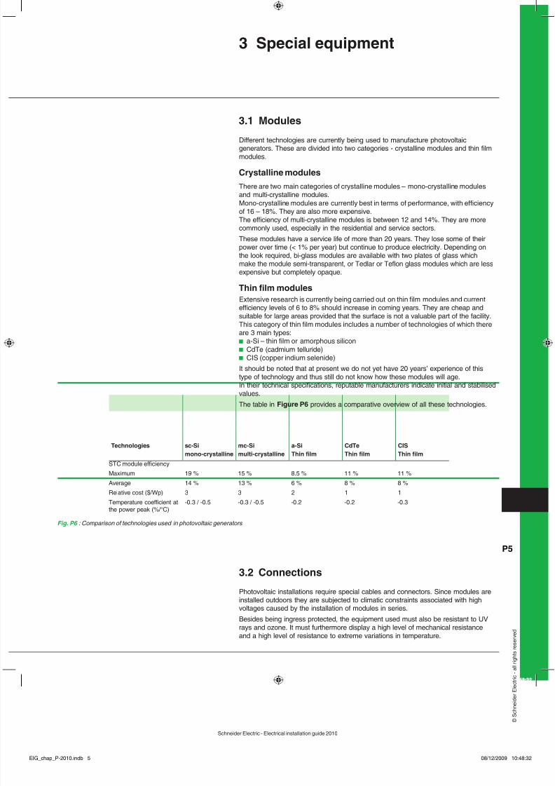
Di erent technologies are currently being used to manu acture photovoltaicgenerators. These are divided into two categories - crystalline modules and thin lmmodules.
Crystalline modulesThere are two main categories o crystalline modules – mono-crystalline modulesand multi-crystalline modules.Mono-crystalline modules are currently best in terms o per ormance, with e ciencyo 16 – 18%. They are also more expensive.The e ciency o multi-crystalline modules is between 12 and 14%. They are morecommonly used, especially in the residential and service sectors.These modules have a service li e o more than 20 years. They lose some o theirpower over time (< 1% per year) but continue to produce electricity. Depending onthe look required, bi-glass modules are available with two plates o glass whichmake the module semi-transparent, or Tedlar or Tefon glass modules which are less
expensive but completely opaque.Thin flm modulesExtensive research is currently being carried out on thin lm modules and currente ciency levels o 6 to 8% should increase in coming years. They are cheap andsuitable or large areas provided that the sur ace is not a valuable part o the acility.This category o thin lm modules includes a number o technologies o which thereare 3 main types:b a-Si – thin lm or amorphous siliconb CdTe (cadmium telluride)b CIS (copper indium selenide)It should be noted that at present we do not yet have 20 years’ experience o thistype o technology and thus still do not know how these modules will age.In their technical speci cations, reputable manu acturers indicate initial and stabilisedvalues.The table in Figure P6 provides a comparative overview o all these technologies.
Fig. P6 : Comparison o technologies used in photovoltaic generators
Photovoltaic installations require special cables and connectors. Since modules areinstalled outdoors they are subjected to climatic constraints associated with highvoltages caused by the installation o modules in series.Besides being ingress protected, the equipment used must also be resistant to UVrays and ozone. It must urthermore display a high level o mechanical resistanceand a high level o resistance to extreme variations in temperature.
The voltage drop between the PV array and the inverter must be calculated and thismust not exceed 3% or nominal current (UTE recommendation: 1%).The DC cables used should be double-insulated single wire cables and since theseare not standardised, cables indicated by the manu acturer as being speci cally orPV should be used.
ConnectorsIn general, photovoltaic modules are supplied with two cables equipped with onemale and one emale connector. Using these cables, it is possible to connect twomodules installed side by side, thus creating a series without any di culties. Themale connector connects to the emale connector o the ollowing module and so onuntil the required level o direct current is attained.These special connectors including the Multi-Contact MC3 or MC4 with lockingsystems o er protection i touched while they are disconnected. This protectionis necessary since as soon as a photovoltaic module is exposed to irradiation, itsupplies voltage. I the cables connecting the modules are handled (to alter or extendthem) they must either rst be disconnected or the DC isolator or the DC circuit mustbe activated at the input to the connection box.It is also possible to use di erent connectors available on the market. These shouldbe chosen care ully or their quality, contact and male- emale mating to avoid anypoor contact which may lead to overheating and destruction.
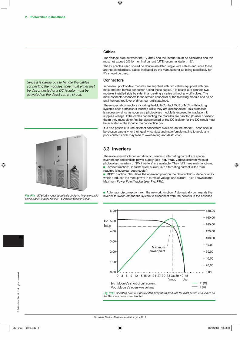
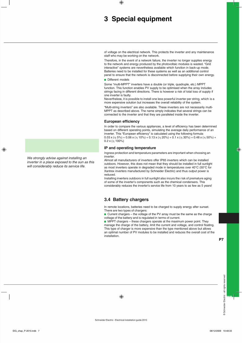
3.3 InvertersThese devices which convert direct current into alternating current are specialinverters or photovoltaic power supply (see Fig. P7a ). Various di erent types ophotovoltaic inverters or “PV inverters” are available. They ul l three main unctions:b Inverter unction: Converts direct current into alternating current in the ormrequired (sinusoidal, square, etc.)b MPPT unction: Calculates the operating point on the photovoltaic sur ace or array
which produces the most power in terms o voltage and current - also known as theMaximum Power Point Tracker (see Fig. P7b ).
b Automatic disconnection rom the network unction: Automatically commands theinverter to switch o and the system to disconnect rom the network in the absence
Since it is dangerous to handle the cables connecting the modules, they must either frst be disconnected or a DC isolator must be activated on the direct current circuit.
Fig. P7a : GT 500E inverter specifcally designed or photovoltaic power supply (source Xantrex – Schneider Electric Group)
0,000 3 6 9 12 15 18 21 24 27 30 33 36
Vmpp VocP (V)
39 42 45
1,00
2,00
3,00
4,00
5,00Isc
Isc : Module’s short circuit currentVoc : Module’s open wire voltage
Impp
6,00 180,00
Maximumpower point
160,00
140,00
120,00
100,00
80,00
60,00
40,00
20,00
0,00
I (A)
Fig. P7b : Operating point o a photovoltaic array which produces the most power, also known as the Maximum Power Point Tracker
o voltage on the electrical network. This protects the inverter and any maintenancesta who may be working on the network.
There ore, in the event o a network ailure, the inverter no longer supplies energyto the network and energy produced by the photovoltaic modules is wasted. “Gridinteractive” systems are nevertheless available which unction in back-up mode.Batteries need to be installed or these systems as well as an additional controlpanel to ensure that the network is disconnected be ore supplying their own energy.b Di erent modelsSome “multi-MPPT” inverters have a double (or triple, quadruple, etc.) MPPT
unction. This unction enables PV supply to be optimised when the array includesstrings acing in di erent directions. There is however a risk o total loss o supply ione inverter is aulty.Nevertheless, it is possible to install one less power ul inverter per string, which is amore expensive solution but increases the overall reliability o the system.“Multi-string inverters” are also available. These inverters are not necessarily multi-MPPT as described above. The name simply indicates that several strings can beconnected to the inverter and that they are paralleled inside the inverter.
European e fciencyIn order to compare the various appliances, a level o e ciency has been determinedbased on di erent operating points, simulating the average daily per ormance o aninverter. This “European e ciency” is calculated using the ollowing ormula:0.03 x ( η 5%) + 0.06 x ( η 10%) + 0.13 x ( η 20%) + 0.1 x ( η 30%) + 0.48 x ( η 50%) +0.2 x ( η 100%)
IP and operating temperatureIngress protection and temperature parameters are important when choosing aninverter.Almost all manu acturers o inverters o er IP65 inverters which can be installedoutdoors. However, this does not mean that they should be installed in ull sunlightas most inverters operate in degraded mode in temperatures over 40°C (50°C orXantrex inverters manu actured by Schneider Electric) and thus output power isreduced.Installing inverters outdoors in ull sunlight also incurs the r isk o premature agingo some o the inverter’s components such as the chemical condensers. Thisconsiderably reduces the inverter’s service li e rom 10 years to as ew as 5 years!
3.4 Battery chargersIn remote locations, batteries need to be charged to supply energy a ter sunset.There are two types o chargers:b Current chargers – the voltage o the PV array must be the same as the chargevoltage o the battery and is regulated in terms o current.b MPPT chargers – these chargers operate at the maximum power point. Theymanage the charge o the battery, limit the current and voltage, and control foating.This type o charger is more expensive than the type mentioned above but allowsan optimal number o PV modules to be installed and reduces the overall cost o theinstallation.
We strongly advise against installing an inverter in a place exposed to the sun as this will considerably reduce its service li e.
P - Photovoltaic installations 4 Installation requirements
4. O grid installation
Historically, these were the rst places in which photovoltaic systems were used,supplying telecommunication relay stations or remote settlements which were di cultto access and could not be connected to the network.They remain one o the only means o supplying electricity to 2 billion people whocurrently do not have access to it.In order to size these installations correctly, it is rst necessary to identi y the loadcurve required and the number o days where the installation will not be exposed tosunlight in order to identi y how much energy needs to be stored in the batteries. Thisin ormation is used to determine the size and type o batteries required.Then, the sur ace area o the photovoltaic sensors must be calculated to ensure thatthe batteries can be recharged in the worst case scenario (shortest day o the year).
Specifc issuesThis method entails over-sizing the system to ensure continuity once or twice a year.As a result, this type o installation is very expensive!It should be noted that according to the EPIA (European Photovoltaic Industry
Association) this type o installation will account or 20% o the photovoltaic market in2012 and 40% in 2030.
StorageStorage is crucial to this type o installation.Several types o batteries are available:b Lead batteriesThese batteries operate in cycles (charge/discharge). Open batteries arerecommended to prevent infating which may occur due to excessively rapid chargingand large emissions o hydrogen.Their purchase price is certainly their main advantage although they have shortservice lives. This is infuenced by the depth o discharging but they last no morethan 2 or 3 years at a discharging rate o 50% and above. Furthermore, deepdischarging may “kill” the battery. There ore, when operating such equipment at aremote site, the batteries should be changed on a regular basis to maintain theircharging per ormance.b Ni-Cd or Nickel Cadmium batteriesThese batteries have the advantage o being much less sensitive to extremetemperature conditions and deep charging or discharging. They have a much longerservice li e (5 to 8 years) but are more expensive to purchase. However, the costo the Wh stored over the service li e o the installation is lower than that o leadbatteries.b Li-ion batteriesThese are the batteries o the uture or these types o operations. They areinsensitive to deep discharging and have a service li e o up to 20 years. At present,they are prohibitively expensive but prices are set to all by 2012 with the start omass production. They will there ore become the most economic variety or this typeo usage.
4.2 Connected to the public network Owners o power generation systems connected to the network have 2 options:b Sell all the power they produce (option known as “total sale”). For this option, aseparate connection must be established to the network, apart rom the connection
or consumption. This also requires an administrative declaration.b Use the power they produce locally as required and only sell the excess (optionknown as “sale o excess”) which has two bene ts:v The di erence in the rates payable by the producer (purchase) and the consumer(sale)v It is not necessary to establish a new connection which may be expensive andrequires an administrative declaration.Since di erent rates are charged, a pro tability analysis should be carried out tochoose the best option.
Installations connected to the network – 3 important pointsThe ollowing points are important to note with regard to installations connected tothe network:b In contrast to independent installations, no correlation is required betweenconsumption or the building and output.For the “total sale” option, the two elements are completely independent.For the “sale o excess” option, the network will compensate when production doesnot cover consumption.b The network must be present in order to supply and sell energy. Furthermore,energy distributors require automatic disconnection systems to be in place incase o incidents on the network. When activated, these stop supply and there oresales. Reconnection occurs automatically when the network returns to its nominaloperating conditions.b As a general rule, no provision is made or local storage using batteries or othermeans. This is true or mainland France where there is a high quality network withthe capacity to absorb all the energy produced.However, the system does have one ault. I the network ails, owners o installationswho are also generally consumers are le t with a power generation acility whichthey cannot use (see previous point). In countries or towns with requent networkincidents, systems are being developed which include batteries. Xantrex, asubsidiary o Schneider Electric, is the leading provider o these systems worldwide.
4.3 Sa ety devices
Protecting people and property against electrical hazardsb In terms o direct current, a DC isolator is compulsory as, even though aconnector can be disconnected when live, an electric arc may occur and damagethe connectors i photovoltaic modules are exposed to light. There are currently twomethods or installing these DC isolators. They can either be integrated into the PVinverter or placed in an external enclosure.I more than three strings need to be paralleled or the same inverter input wheninstalling a PV array, the statutory sa ety devices are much more complex. Indeed,current reversal may occur in a string which would be destroyed under the combinedpower o all the other strings.Schneider Electric also supplies paralleling enclosures or strings as well asprotection units which include a general load break switch enabling work to becarried out sa ely upstream o this unit even in daylight.b In terms o alternating current, a more standard range o sa ety devices isavailable. The cable between the inverter and the network must be protectedsince any ault in this connection would be exposed to the short circuit power othe network. A sa ety device protecting against short circuits should there ore bepositioned close to the network connection, and the inverter should disconnectautomatically in the absence o voltage in the authorised range. Schneider Electricsupplies enclosures including upstream and downstream sa ety devices.
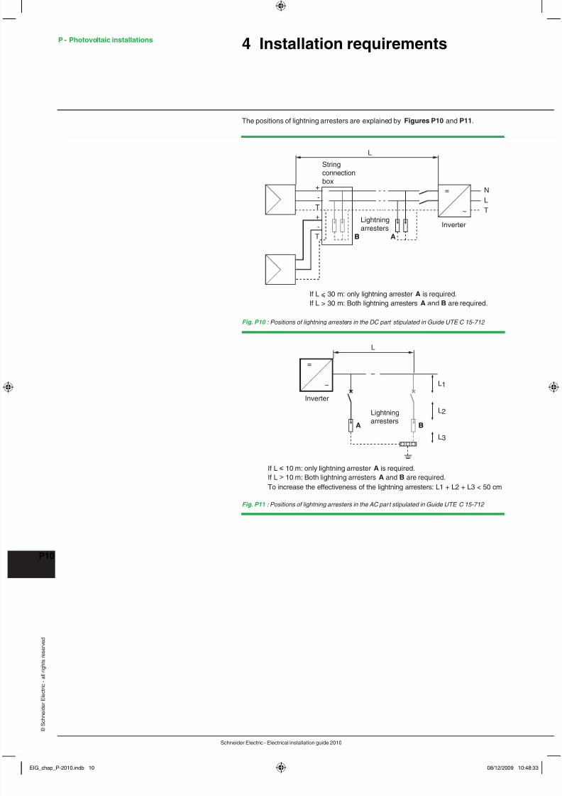
Protecting PV installations against the e ects o lightningOvervoltage may occur in electrical installations or various reasons. This may becaused by:b The distribution network as a result o lightning or any work carried outb Lightning bolts (nearby/on buildings and PV installations, or on lightningconductors)b Variations in the electrical eld due to lightning.Like all outdoor structures, photovoltaic installations are exposed to the risk olightning which varies rom region to region.b EquipotentialityEquipotentiality is the rst sa eguard to put in place and entails connecting allconductive elements and metal conductive parts in the photovoltaic installation usingan equipotential conductor.The minimum section or this conductor is:v 4 mm² in the absence o a lightning conductor or i a lightning conductor is in placebut not connected to the installationv 10 mm² i the installation is connected to the building’s lightning conductor (thismust be connected by a cable o 10 mm² i the lightning conductor is less than 2.5m
A PV array is made up o a number o modules in series or parallel, correspondingto the input characteristics o the inverter. However, since these modules areinterconnected, the array is very sensitive to shade or di erences in terms o thedirection aced.By ollowing a ew simple cabling rules, supply can be optimised and any operatingproblems may be avoided.
Position o the panelsI , when installing a PV array on a roo , panels need to ace in di erent directions, it isessential to assemble at least one string per direction and ensure each string is acingin just one direction to ensure optimised supply. Each string must be connected to aspecifc inverter (or to inputs o a multi-MPPT inverter - see Section 3).I this instruction is not observed, the array will not be damaged but supply will bereduced, thus increasing the time needed or a return on investment.
Shade
Besides the risk o destruction o shaded modules within a PV array due to the “hotspot phenomenon” as described in Paragraph 2.2 or which manu acturers havedevised solutions, research conducted by the Institut National des Energies Solaires(INES – France’s national institute or solar energy) suggests that shading o 10% othe sur ace area o a string may cause more than a 30% reduction in output!It is there ore important to eliminate direct shading. However, in many cases this isdi cult (trees, chimney, neighbouring wall, pylon, etc.).I a PV array includes several strings:b I possible, shaded modules should be included in a single stringb Otherwise, a technology should be chosen which responds better to di use lightthan direct light
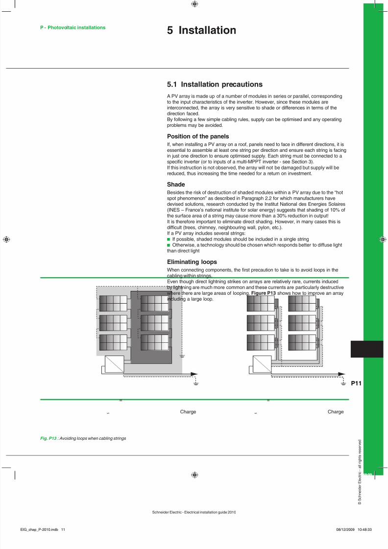
Eliminating loopsWhen connecting components, the rst precaution to take is to avoid loops in thecabling within strings.Even though direct lightning strikes on arrays are relatively rare, currents induced
by lightning are much more common and these currents are particularly destructivewhere there are large areas o looping. Figure P 3 shows how to improve an arrayincluding a large loop.
5.2 Architectures or installations connected to the
network General RulesWhere photovoltaic installations are connected to the network and energy is sold, itis necessary to optimise e ciency and reduce installation costs. With this in mind,a relatively high DC operating voltage o between 200 and 500 V is o ten used orresidential applications, with up to 1000 V being used or applications requiring ahigher level o power.All the modules in a PV array should be identical (same brand and same type) andselected to supply the same level o power. For example, in the PW1700 range, theyshould all be 180 W, even though there are three power levels (170 W, 180 W and190 W) in this range manu actured by Photowatt.In practice, the protection units (DC and AC units) should be positioned close to theinverters or ease o maintenance.
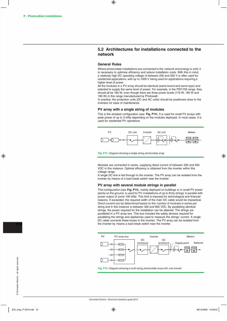
PV array with a single string o modulesThis is the simplest con guration (see Fig. P 4 ). It is used or small PV arrays withpeak power o up to 3 kWp depending on the modules deployed. In most cases, it isused or residential PV operations.
Modules are connected in series, supplying direct current o between 200 and 500
VDC in this instance. Optimal e ciency is obtained rom the inverter within thisvoltage range.A single DC line is ed through to the inverter. The PV array can be isolated rom theinverter by means o a load break switch near the inverter.
PV array with several module strings in parallelThis con guration (see Fig. P 5 ), mainly deployed on buildings or in small PV powerplants on the ground, is used or PV installations o up to thirty strings in parallel withpower output o some 100 kWp. This limit is imposed or technological and nancialreasons. I exceeded, the required width o the main DC cable would be impractical.Direct current can be determined based on the number o modules in series perstring and in this instance is between 300 and 600 VDC. By paralleling identicalstrings, the power required or the installation can be attained. The strings areparalleled in a PV array box. This box includes the sa ety devices required orparalleling the strings and appliances used to measure the strings’ current. A singleDC cable connects these boxes to the inverter. The PV array can be isolated rom
the inverter by means a load break switch near the inverter.
=
~
MetersInverterDC unit AC unitPV
kWh kWh
Fig. P14 : Diagram showing a single-string photovoltaic array
MetersPV array box InverterPV
Network
kWh kWh
Supply point =
~
DCenclosure
ACenclosure
Fig. P15 : Diagram showing a multi-string photovoltaic array with one inverter
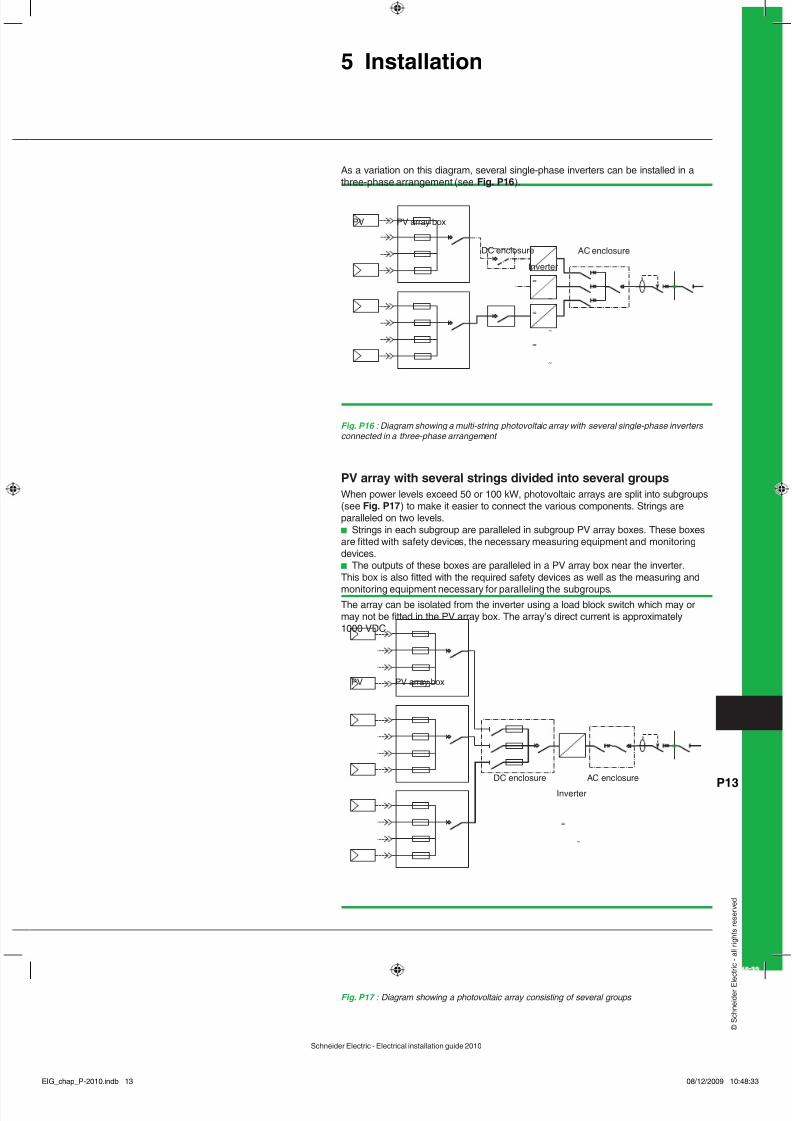
PV array with several strings divided into several groupsWhen power levels exceed 50 or 100 kW, photovoltaic arrays are split into subgroups(see Fig. P 7 ) to make it easier to connect the various components. Strings areparalleled on two levels.b Strings in each subgroup are paralleled in subgroup PV array boxes. These boxesare tted with sa ety devices, the necessary measuring equipment and monitoringdevices.b The outputs o these boxes are paralleled in a PV array box near the inverter.This box is also tted with the required sa ety devices as well as the measuring and
monitoring equipment necessary or paralleling the subgroups.The array can be isolated rom the inverter using a load block switch which may ormay not be tted in the PV array box. The array’s direct current is approximately1000 VDC.
=
~
=
~
=
~
PV array box
Inverter
PV
DC enclosure AC enclosure
Fig. P16 : Diagram showing a multi-string photovoltaic array with several single-phase inverters connected in a three-phase arrangement
As a variation on this diagram, several single-phase inverters can be installed in athree-phase arrangement (see Fig. P 6 ).
=
~
PV array box
Inverter
PV
DC enclosure AC enclosure
Fig. P17 : Diagram showing a photovoltaic array consisting o several groups
Calculating a photovoltaic arrayIt is absolutely essential to take account o location (geographic location, latitude,altitude, shade, etc.) and installation actors (direction aced, angle, etc.).Firstly, the approximate power output may be calculated based on the availablesur ace area:10 m² = 1 kWp7140 m² (= ootball ground) = 700 kWpThe PV array should always be arranged around the inverter. The calculationsinvolved should compare the characteristics o the modules and those o the inverterwith a view to identi ying the optimal con guration.b String composition:NB: Number o modules x Voc (at t° min) < inverter VmaxThe no load voltage o the string (Voc x number o modules in series) at theminimum temperature o the installation location must be lower than the inverter’s
maximum input voltage.=> This must be strictly observed. Otherwise the inverter may be destroyed.Apart rom the a orementioned rule or preventing destruction o the inverterNumber o modules x Voc (at t° min) < inverter Vmax – two other limits must beobserved:v Number o modules x Vmpp (at t° max) > inverter VminThe operating voltage (Vm x number o modules in series at all temperatures at theinstallation location) should all within the inverter’s MPPT voltage range. Otherwise,the inverter will stall and energy supply will cease.v Isc strings < inverter I maxThe total Isc current or strings in parallel must be lower than the maximum inputcurrent or the inverter. Otherwise, the inverter limits the supply o energy delivered tothe network.
Inverter specifcationsb In Europe, the power level o the inverter must be between 0.8 and 1 times the
power o the array:0.8 < Pinverter / Parray < 1v Below this (under 0.8 Parray), the inverter limits power signi cantly. The energysold to the network will thus be in erior to that which the panels are capable osupplying and there ore it will take longer to secure a return on investment.v Above this (over Parray), the inverter is too large or the power level o the array.Again, it will take longer to secure a return on investment.b Single-phase or three-phaseA decision should be made over these two options in consultation with the localenergy distributor based on the devices available in manu acturers’ product ranges,o ten within the ollowing limits:v Inverter Pn < 10 kW => single phase inverterv 10 kW < Pn < 100 kW => either three-phase inverter(s) or single-phase inverterssplit between the three phases and neutral. The management o unbalancesbetween phases needs to be checked in this instance.v Pn > 100 kW => three-phase inverter(s)b
Con guration so twareManu acturers o inverters help design o ces and installers to size strings orresidential and service sector installations based on the equipment available bysupplying sizing so tware.
5.4 Installation typeThe installation type is a actor which should not be neglected since, in countriesincluding France, the purchase price or power supplied is dependent on this. Alongwith shading, it should be taken into account when choosing a module.There are three installation types – building integrated, partially integrated andground-based:b Building Integrated PhotoVoltaic (BIPV)This installation type ul ls a dual role (energy supply and roo waterproo ng,shading, etc.).
b Partially integratedThis is the simplest assembly to install and, most importantly, does not alter the
water resistance o a roo . However, its major drawback is that, in France, operatorscannot charge the highest rate or it. This installation type is most commonly used inGermany and Switzerland.b Ground-basedThis installation type is used or power supply plants covering large areas(photovoltaic arms). Again, in France it is not eligible or the highest purchase price.
Since the pro tability o photovoltaic installations depends mainly on them beingoperational, it is essential to ensure that they are permanently unctional. The best
way o ensuring this is to acquire a monitoring system or the installation. This systemshould noti y all aults immediately and be capable o detecting dri ts in output.
6. Types o monitoringSeveral types o monitoring are available or installations:b Systems which communicate with the inverters and are able to monitor allelectrical values relating to output rom the installation as well as the condition o theinvertersb Systems without communication protocols or the inverters but tted withmeasurement inputs capable o monitoring photovoltaic outputb Hybrid systems supplementing in ormation rom the inverters with measurementswhich are external to the installation such as solar radiation and temperature.In ormation on the modules at the output o the inverters can only be correlatedacross the installation as a whole by systems capable o measuring solar radiation.Indeed, since output orecasts generally rely on meteorological statistics, it is quitedi cult to interpret output data without correlating them to actual solar radiation. Anabnormally low level o output may be caused by:v A low level o solar radiation over a certain period o time (and which is abnormalbased on meteorological statistics)v A problem with the modules (clogging, shade, connection ault, etc.)v A unctional problem with the inverterIt is only possible to identi y these aults by equipping the installation with solarradiation and temperature sensors and comparing the output capacity with actualoutput.Depending on the size o the installation, individual monitoring or monitoring bygroup o photovoltaic module strings may be possible in order to detect abnormalvariations in output between strings.
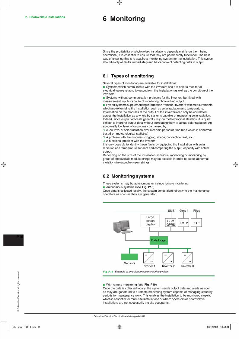
6.2 Monitoring systemsThese systems may be autonomous or include remote monitoring.b Autonomous systems (see Fig. P 8 )Once data is collected locally, the system sends alerts directly to the maintenanceoperators as soon as they are generated.
Fig. P18 : Example o an autonomous monitoring system
Largescreendisplay
Data logger
SMS
SMTP FTP
@mail Files
GSMGPRS
Inverter 1Sensors
Inverter 2 Inverter 3
=
~
=
~
=
~
b With remote monitoring (see Fig. P )Once the data is collected locally, the system sends output data and alerts as soonas they are generated to a remote monitoring system capable o managing stand-by
periods or maintenance work. This enables the installation to be monitored closely,which is essential or multi-site installations or where operators o photovoltaicinstallations are not necessarily the site occupants.
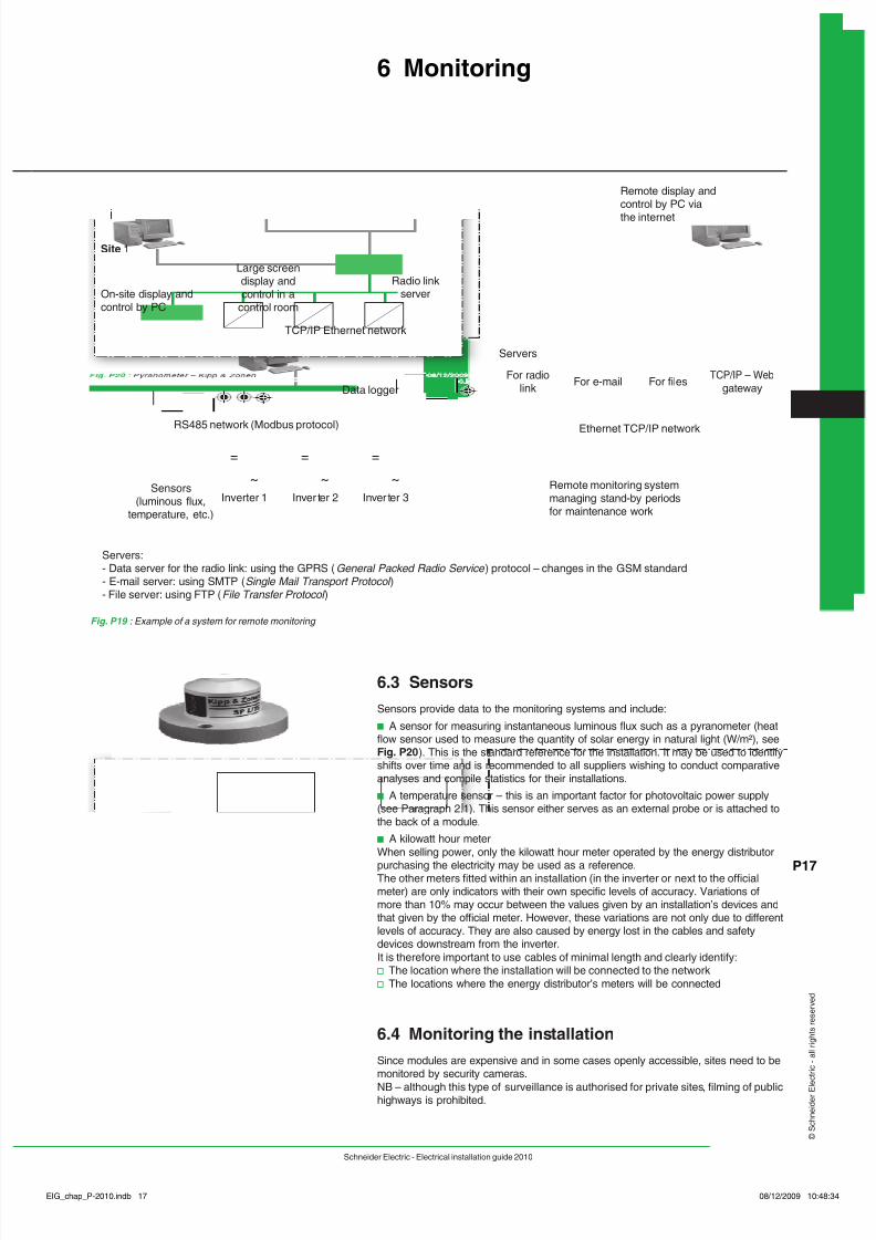
6.3 SensorsSensors provide data to the monitoring systems and include:b A sensor or measuring instantaneous luminous fux such as a pyranometer (heatfow sensor used to measure the quantity o solar energy in natural light (W/m²), seeFig. P20 ). This is the standard re erence or the installation. It may be used to identi yshi ts over time and is recommended to all suppliers wishing to conduct comparativeanalyses and compile statistics or their installations.b A temperature sensor – this is an important actor or photovoltaic power supply(see Paragraph 2.1). This sensor either serves as an external probe or is attached tothe back o a module.b A kilowatt hour meterWhen selling power, only the kilowatt hour meter operated by the energy distributor
purchasing the electricity may be used as a re erence.The other meters tted within an installation (in the inverter or next to the o cialmeter) are only indicators with their own speci c levels o accuracy. Variations omore than 10% may occur between the values given by an installation’s devices andthat given by the o cial meter. However, these variations are not only due to di erentlevels o accuracy. They are also caused by energy lost in the cables and sa etydevices downstream rom the inverter.It is there ore important to use cables o minimal length and clearly identi y:v The location where the installation will be connected to the networkv The locations where the energy distributor’s meters will be connected
6.4 Monitoring the installationSince modules are expensive and in some cases openly accessible, sites need to bemonitored by security cameras.
NB – although this type o surveillance is authorised or private sites, lming o publichighways is prohibited.
Fig. P19 : Example o a system or remote monitoring
Site 2
On-site display andcontrol by PC
Site 1
TCP/IP Ethernet network
RS485 network (Modbus protocol)
Data logger
Ethernet TCP/IP network
Inverter 1
Servers:- Data server for the radio link: using the GPRS ( General Packed Radio Service ) protocol – changes in the GSM standard- E-mail server: using SMTP ( Single Mail Transport Protocol )- File server: using FTP ( File Transfer Protocol )
For radiolink For e-mail For files
TCP/IP – Web
gateway
Inver ter 2 Inver ter 3
Radio linkserver
=
~
=
~
=
~
Servers
Large screendisplay andcontrol in a
control room
Sensors(luminous flux,
temperature, etc.)
Remote display andcontrol by PC via
the internet
Remote monitoring systemmanaging stand-by periodsfor maintenance work
P - Photovoltaic installations 7 Additional In ormation
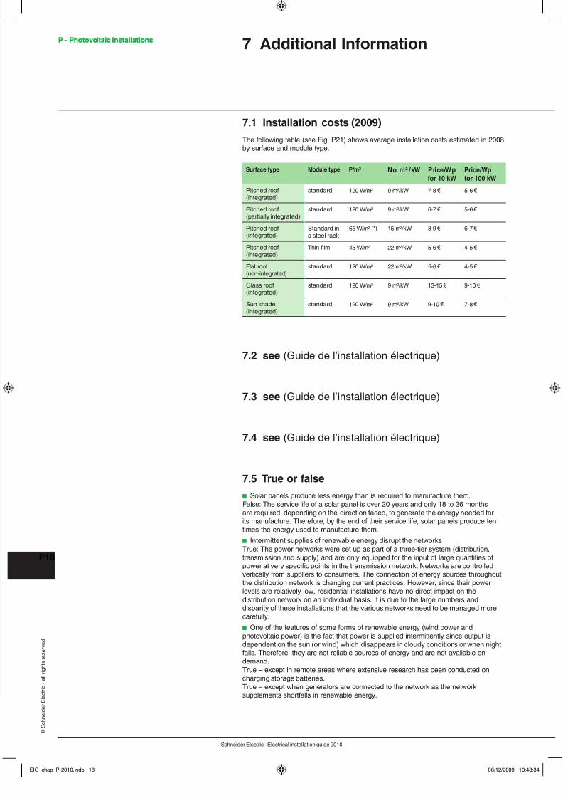
7. Installation costs (200 )
The ollowing table (see Fig. P21) shows average installation costs estimated in 2008by sur ace and module type.
Surface type Module type P/m² No. m² /kW Price/Wpfor 0 kW
Price/Wpfor 00 kW
Pitched roo(integrated)
standard 120 W/m² 9 m²/kW 7-8 € 5-6 €
Pitched roo(partially integrated)
standard 120 W/m² 9 m²/kW 6-7 € 5-6 €
Pitched roo(integrated)
Standard ina steel rack
65 W/m² (*) 15 m²/kW 8-9 € 6-7 €
Pitched roo(integrated)
Thin flm 45 W/m² 22 m²/kW 5-6 € 4-5 €
Flat roo(non-integrated)
standard 120 W/m² 22 m²/kW 5-6 € 4-5 €
Glass roo(integrated)
standard 120 W/m² 9 m²/kW 13-15 € 9-10 €
Sun shade(integrated)
standard 120 W/m² 9 m²/kW 9-10 € 7-8 €
7.2 see (Guide de l’installation électrique)
7.3 see (Guide de l’installation électrique)
7.4 see (Guide de l’installation électrique)
7.5 True or alseb Solar panels produce less energy than is required to manu acture them.False: The service li e o a solar panel is over 20 years and only 18 to 36 monthsare required, depending on the direction aced, to generate the energy needed orits manu acture. There ore, by the end o their service li e, solar panels produce tentimes the energy used to manu acture them.b Intermittent supplies o renewable energy disrupt the networksTrue: The power networks were set up as part o a three-tier system (distribution,
transmission and supply) and are only equipped or the input o large quantities opower at very speci c points in the transmission network. Networks are controlledvertically rom suppliers to consumers. The connection o energy sources throughoutthe distribution network is changing current practices. However, since their powerlevels are relatively low, residential installations have no direct impact on thedistribution network on an individual basis. It is due to the large numbers anddisparity o these installations that the various networks need to be managed morecare ully.b One o the eatures o some orms o renewable energy (wind power andphotovoltaic power) is the act that power is supplied intermittently since output isdependent on the sun (or wind) which disappears in cloudy conditions or when night
alls. There ore, they are not reliable sources o energy and are not available ondemand.True – except in remote areas where extensive research has been conducted oncharging storage batteries.True – except when generators are connected to the network as the networksupplements short alls in renewable energy.