50

Copyright © 2004, PCI-SIG, All Rights Reserved 2
PCI Express™ Basics & Applications in Communication
Systems
PCI Express™ Basics & Applications in Communication
SystemsAkber Kazmi
PLX TechnologyAkber Kazmi
PLX Technology
Copyright © 2004, PCI-SIG, All Rights Reserved 3PCI-SIG Developers Conference
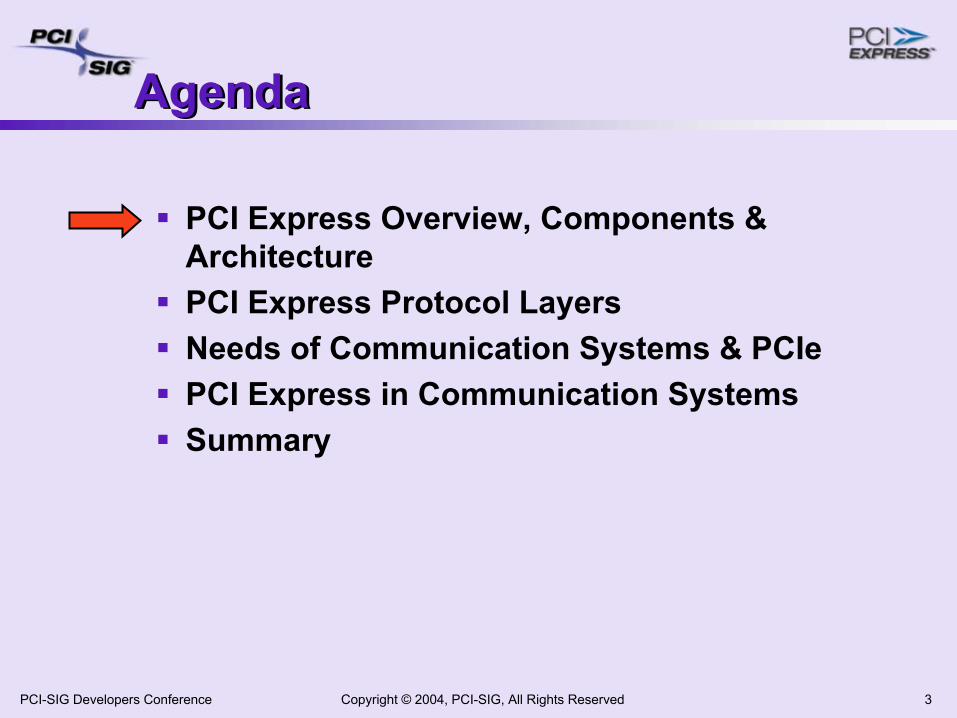
AgendaAgenda
PCI Express Overview, Components & Architecture PCI Express Protocol LayersNeeds of Communication Systems & PCIePCI Express in Communication SystemsSummary
Copyright © 2004, PCI-SIG, All Rights Reserved 4PCI-SIG Developers Conference
PCI Express High Level Overview
PCI Express High Level Overview
Chip/chip and fabric interconnect technologyHigh speed serial, packet based Fully open and standardizedComplete compatibility with PCI & PCI-XCost driver: PCs/Graphics (economies of scale)Advanced features: QoS, Flow Control, data error detection Applicable to wide variety of applications
Servers, Storage, Communications, embeddedExtensive industry support
Copyright © 2004, PCI-SIG, All Rights Reserved 5PCI-SIG Developers Conference
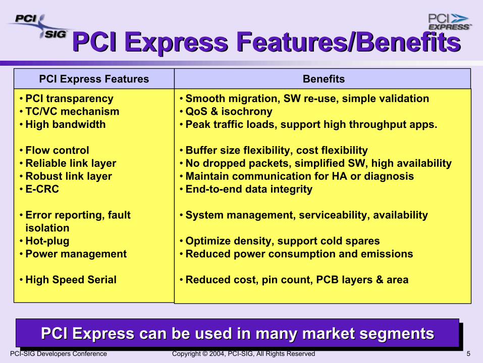
PCI Express Features/BenefitsPCI Express Features/Benefits
PCI Express can be used in many market segmentsPCI Express can be used in many market segmentsPCI Express can be used in many market segments
• PCI transparency• TC/VC mechanism• High bandwidth
• Flow control• Reliable link layer• Robust link layer• E-CRC
• Error reporting, fault isolation
• Hot-plug• Power management
• High Speed Serial
• Smooth migration, SW re-use, simple validation• QoS & isochrony• Peak traffic loads, support high throughput apps.
• Buffer size flexibility, cost flexibility• No dropped packets, simplified SW, high availability• Maintain communication for HA or diagnosis• End-to-end data integrity
• System management, serviceability, availability
• Optimize density, support cold spares• Reduced power consumption and emissions
• Reduced cost, pin count, PCB layers & area
PCI Express Features Benefits
Copyright © 2004, PCI-SIG, All Rights Reserved 6PCI-SIG Developers Conference
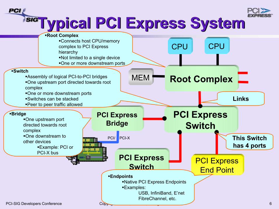
Typical PCI Express SystemTypical PCI Express System
PCI Express Switch
MEM Root Complex
CPUCPU
PCI Express End Point
PCI Express Switch
PCI Express Bridge
J2J1J2
J1J2J1
Root ComplexConnects host CPU/memory
complex to PCI Express hierarchyNot limited to a single deviceOne or more downstream ports
BridgeOne upstream port
directed towards root complexOne downstream to
other devicesExample: PCI or
PCI-X bus
SwitchAssembly of logical PCI-to-PCI bridgesOne upstream port directed towards root
complex One or more downstream portsSwitches can be stackedPeer to peer traffic allowed
EndpointsNative PCI Express EndpointsExamples:
USB, InfiniBand, E’netFibreChannel, etc.
Links
PCI/ PCI-X This Switch has 4 ports
Copyright © 2004, PCI-SIG, All Rights Reserved 7PCI-SIG Developers Conference
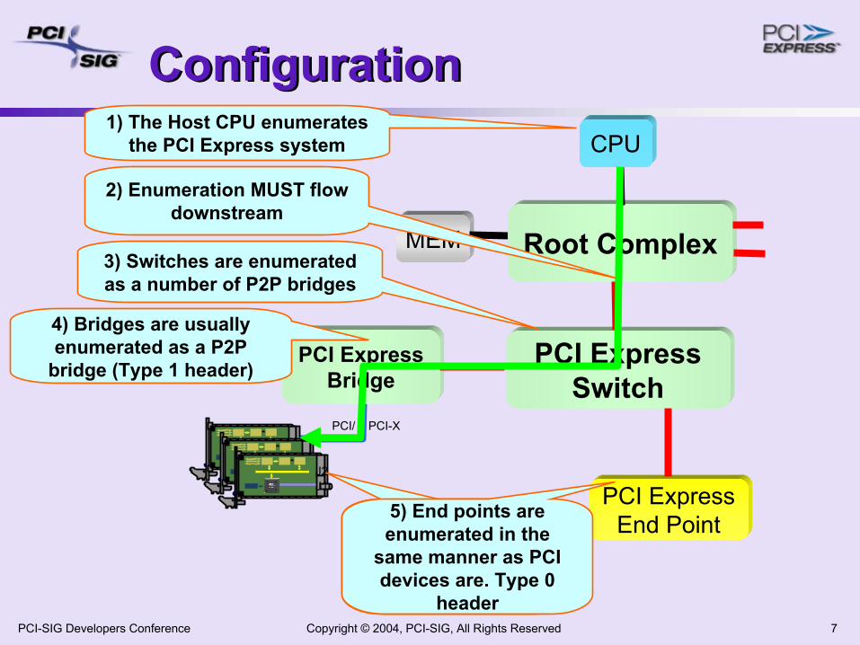
ConfigurationConfiguration
PCI Express Switch
MEM Root Complex
CPU
PCI Express End Point
PCI Express Bridge
J2J1J2
J1J2J1
1) The Host CPU enumerates the PCI Express system
PCI/ PCI-X
2) Enumeration MUST flow downstream
5) End points are enumerated in the
same manner as PCI devices are. Type 0
header
3) Switches are enumerated as a number of P2P bridges
4) Bridges are usually enumerated as a P2P
bridge (Type 1 header)
Copyright © 2004, PCI-SIG, All Rights Reserved 8PCI-SIG Developers Conference
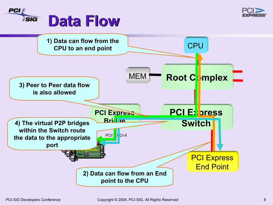
Data FlowData Flow
PCI Express Switch
MEM Root Complex
CPU
PCI Express End Point
PCI Express Bridge
J2J1J2
J1J2J1
PCI/ PCI-X
1) Data can flow from the CPU to an end point
2) Data can flow from an End point to the CPU
3) Peer to Peer data flow is also allowed
4) The virtual P2P bridges within the Switch route
the data to the appropriate port
Copyright © 2004, PCI-SIG, All Rights Reserved 9PCI-SIG Developers Conference
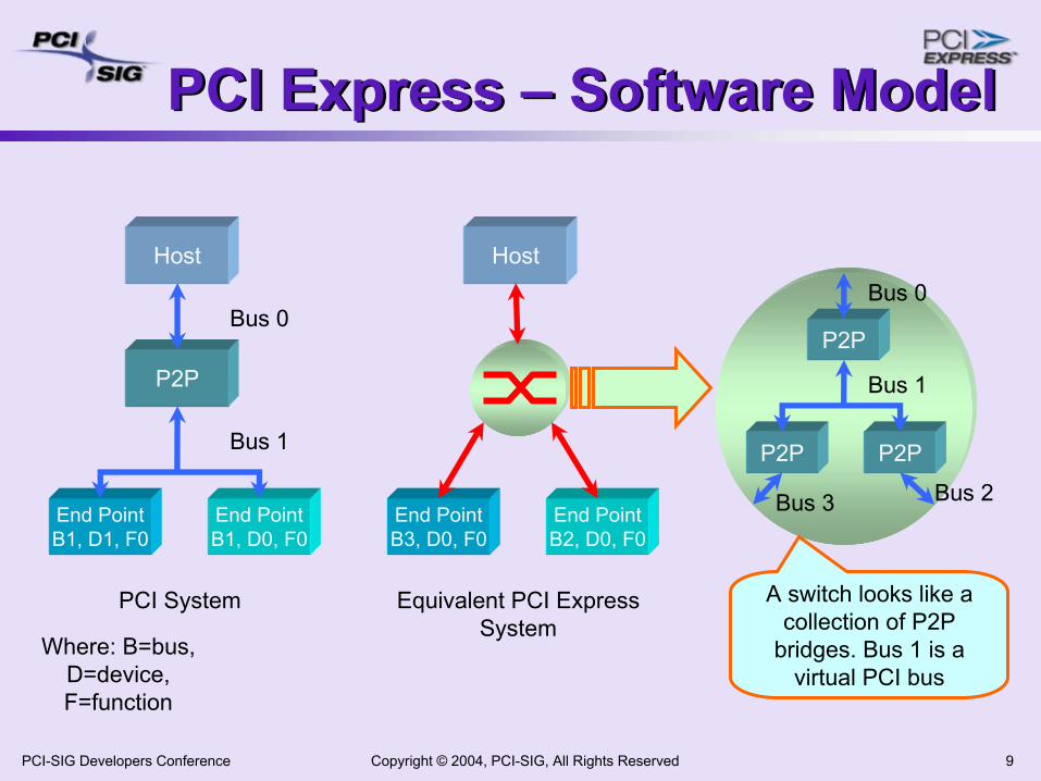
PCI Express – Software ModelPCI Express – Software Model
Host
P2P
End PointB1, D0, F0
End PointB1, D1, F0
Bus 0
Bus 1
Host
End PointB2, D0, F0
End PointB3, D0, F0
PCI System Equivalent PCI Express System
P2P P2P
P2P
Bus 0
Bus 1
Bus 2Bus 3
Where: B=bus, D=device, F=function
A switch looks like a collection of P2P
bridges. Bus 1 is a virtual PCI bus
Copyright © 2004, PCI-SIG, All Rights Reserved 10PCI-SIG Developers Conference
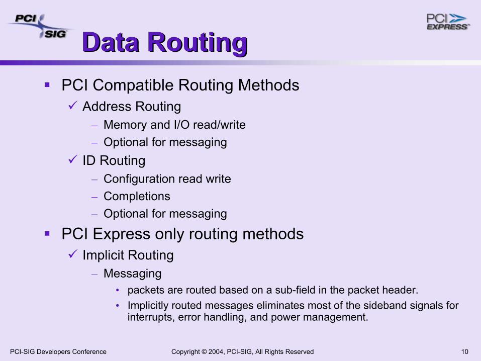
Data RoutingData RoutingPCI Compatible Routing Methods
Address Routing– Memory and I/O read/write– Optional for messaging
ID Routing– Configuration read write– Completions– Optional for messaging
PCI Express only routing methodsImplicit Routing
– Messaging• packets are routed based on a sub-field in the packet header. • Implicitly routed messages eliminates most of the sideband signals for
interrupts, error handling, and power management.
Copyright © 2004, PCI-SIG, All Rights Reserved 11PCI-SIG Developers Conference
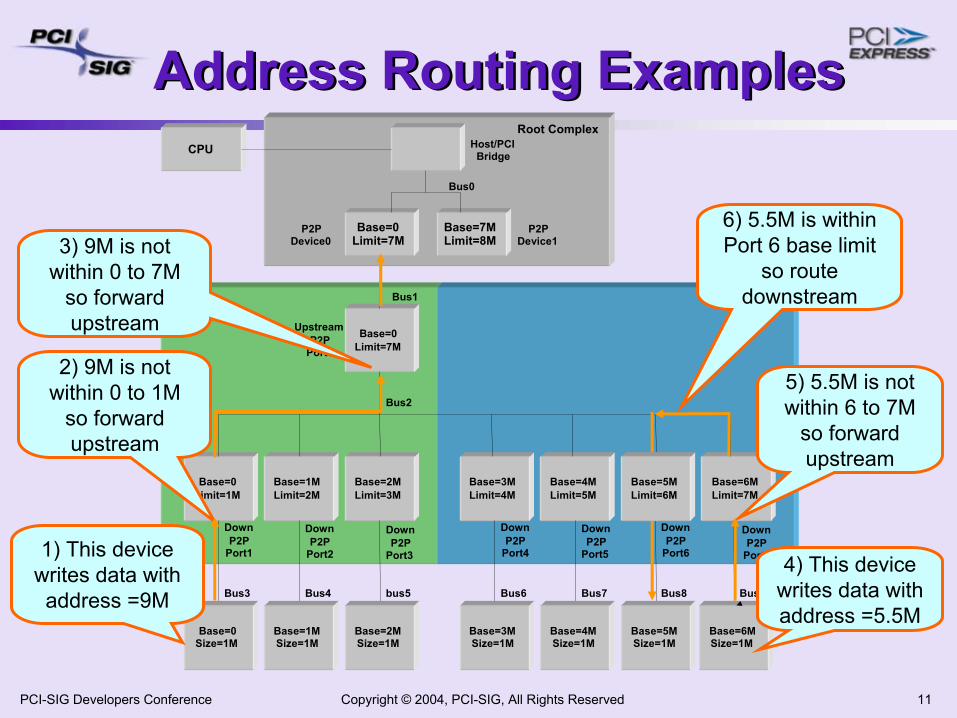
Address Routing ExamplesAddress Routing Examples
Base=0Limit=7M
Base=0Limit=1M
Base=2MLimit=3M
Base=1MLimit=2M
Base=0Size=1M
Base=2MSize=1M
Base=1MSize=1M
CPU
Bus1
Base=0Limit=7M
Base=7MLimit=8M
Bus0
Root Complex
bus5Bus4Bus3
Bus2
Host/PCIBridge
P2PDevice0
P2PDevice1
UpstreamP2P
Port0
DownP2P
Port1
DownP2P
Port3
DownP2P
Port2
Base=3MLimit=4M
Base=4MLimit=5M
Base=6MLimit=7M
Base=3MSize=1M
Base=5MSize=1M
Base=4MSize=1M
Bus8Bus7Bus6
DownP2P
Port4
DownP2P
Port5
Base=6MSize=1M
Bus9
DownP2P
Port6
DownP2P
Port71) This device writes data with address =9M
2) 9M is not within 0 to 1M
so forward upstream
3) 9M is not within 0 to 7M
so forward upstream
4) This device writes data with address =5.5M
5) 5.5M is not within 6 to 7M
so forward upstream
6) 5.5M is within Port 6 base limit
so route downstream
Base=5MLimit=6M
Copyright © 2004, PCI-SIG, All Rights Reserved 12PCI-SIG Developers Conference
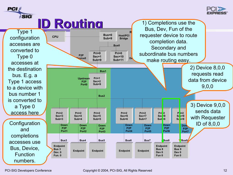
ID RoutingID Routing
Pri=1Sec=2Sub=9
Pri=2Sec=3Sub=3
Pri=2Sec=5Sub=5
Pri=2Sec=4Sub=4
EndpointBus 3Dev. 0Fun. 0
EndpointEndpoint
CPU
Bus1
Pri=0Sec=1Sub=9
Bus=0Sub=9
Pri=0Sec=10Sub=11
Bus0
Root Complex
Bus5Bus4Bus3
Bus2
Host/PCIBridge
P2PDevice0
P2PDevice1
UpstreamP2P
Port0
DownP2P
Port1
DownP2P
Port3
DownP2P
Port2
Pri=2Sec=6Sub=6
Pri=2Sec=7Sub=7
Pri=2Sec=8Sub=8
Pri=2Sec=9Sub=9
Endpoint
EndpointBus 8Dev 0Fun 0
Endpoint
Bus8Bus7Bus6
DownP2P
Port4
DownP2P
Port5
EndpointBus 9Dev 0Fun 0
Bus9
DownP2P
Port6
DownP2P
Port7
Configuration and
completions accesses use Bus, Device,
Function numbers.
Type 1 configuration accesses are converted to
Type 0 accesses at
the destination bus. E.g. a
Type 1 access to a device with bus number 1 is converted to
a Type 0 access here
1) Completions use the Bus, Dev, Fun of the
requester device to route completion data. Secondary and
subordinate bus numbers make routing easy.
2) Device 8,0,0 requests read
data from device 9,0,0
3) Device 9,0,0 sends data
with Requester ID of 8,0,0
Copyright © 2004, PCI-SIG, All Rights Reserved 13PCI-SIG Developers Conference
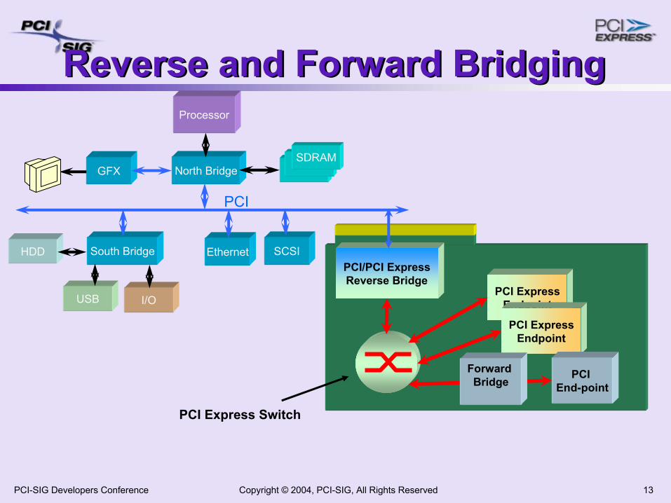
Reverse and Forward BridgingReverse and Forward BridgingProcessor
USB
North BridgeSDRAM
HDD
GFX
South Bridge Ethernet SCSI
I/O
PCI
PCI/PCI ExpressReverse Bridge
PCI Express Switch
PCI ExpressEndpoint
PCI ExpressEndpoint
PCI End-point
Forward Bridge
Copyright © 2004, PCI-SIG, All Rights Reserved 14PCI-SIG Developers Conference
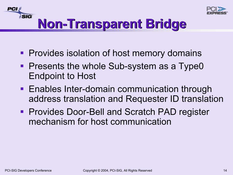
Non-Transparent BridgeNon-Transparent Bridge
Provides isolation of host memory domains Presents the whole Sub-system as a Type0 Endpoint to HostEnables Inter-domain communication through address translation and Requester ID translationProvides Door-Bell and Scratch PAD register mechanism for host communication
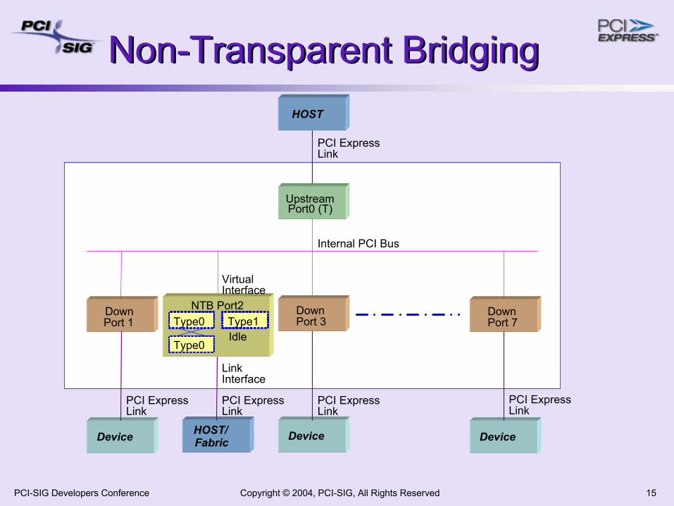
Copyright © 2004, PCI-SIG, All Rights Reserved 15PCI-SIG Developers Conference
Non-Transparent Bridging Non-Transparent Bridging HOST
UpstreamPort0 (T)
DownPort 1
DownPort 7
Device DeviceHOST/Fabric Device
PCI ExpressLink
Internal PCI Bus
Type0
Type0
NTB Port2
VirtualInterface
LinkInterface
Type1DownPort 3
Idle
PCI ExpressLink
PCI ExpressLink
PCI ExpressLink
PCI ExpressLink
Copyright © 2004, PCI-SIG, All Rights Reserved 16PCI-SIG Developers Conference
AgendaAgenda
PCI Express Overview, Components & Architecture PCI Express Protocol LayersNeeds of Communication Systems & PCIePCI Express in Communication SystemsSummary
Copyright © 2004, PCI-SIG, All Rights Reserved 17PCI-SIG Developers Conference
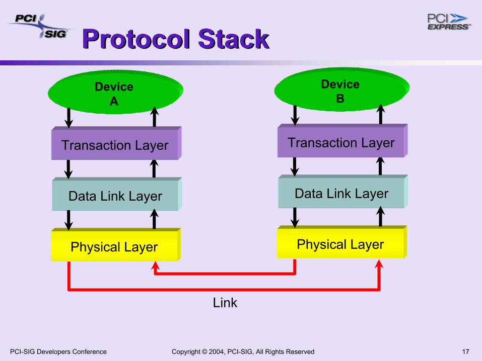
Protocol Stack Protocol Stack
Data Link Layer
Physical Layer
DeviceA
Transaction Layer
Data Link Layer
Physical Layer
DeviceB
Transaction Layer
Link
Copyright © 2004, PCI-SIG, All Rights Reserved 18PCI-SIG Developers Conference
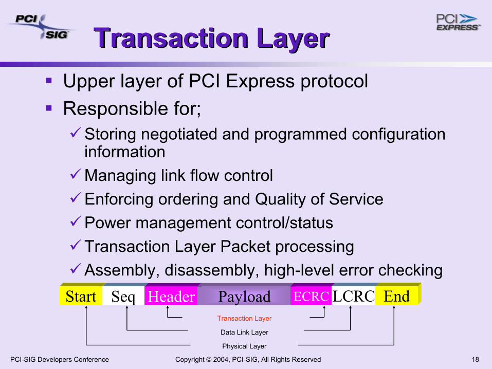
Transaction LayerTransaction LayerUpper layer of PCI Express protocolResponsible for;
Storing negotiated and programmed configuration informationManaging link flow controlEnforcing ordering and Quality of ServicePower management control/statusTransaction Layer Packet processingAssembly, disassembly, high-level error checking
Data Link Layer
Physical Layer
Transaction Layer
Start Seq Header Payload ECRC LCRC End
Copyright © 2004, PCI-SIG, All Rights Reserved 19PCI-SIG Developers Conference
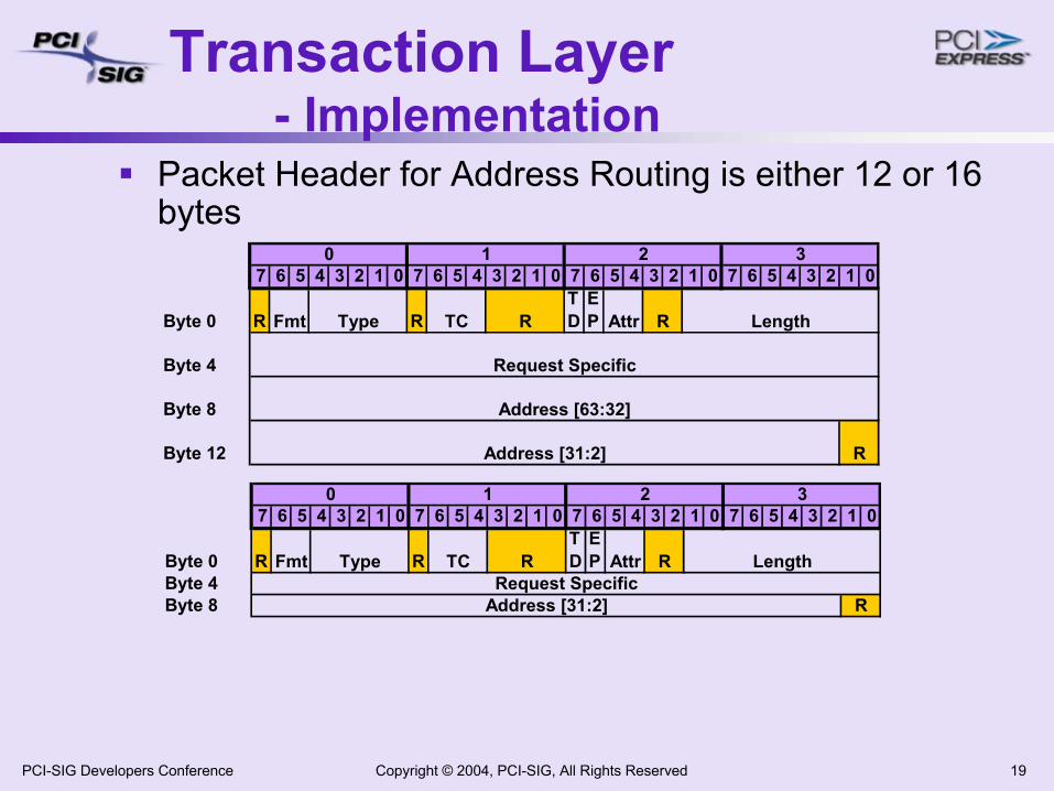
Transaction Layer - Implementation
7 6 5 4 3 2 1 0 7 6 5 4 3 2 1 0 7 6 5 4 3 2 1 0 7 6 5 4 3 2 1 0
Byte 0 R RTD
EP
Byte 4
Byte 8
Byte 12
Address [63:32]
Address [31:2] R
Attr R Length
Request Specific
Fmt Type TC R
0 1 2 3
7 6 5 4 3 2 1 0 7 6 5 4 3 2 1 0 7 6 5 4 3 2 1 0 7 6 5 4 3 2 1 0
Byte 0 R RTD
EP
Byte 4Byte 8 Address [31:2] R
Attr R LengthRequest Specific
Fmt Type TC R
0 1 2 3
Packet Header for Address Routing is either 12 or 16 bytes
Copyright © 2004, PCI-SIG, All Rights Reserved 20PCI-SIG Developers Conference
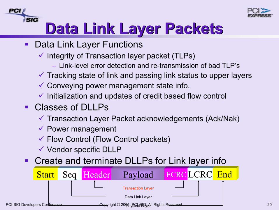
Data Link Layer PacketsData Link Layer PacketsData Link Layer Functions
Integrity of Transaction layer packet (TLPs)– Link-level error detection and re-transmission of bad TLP’s
Tracking state of link and passing link status to upper layersConveying power management state info.Initialization and updates of credit based flow control
Classes of DLLPsTransaction Layer Packet acknowledgements (Ack/Nak)Power managementFlow Control (Flow Control packets)Vendor specific DLLP
Create and terminate DLLPs for Link layer info
Data Link Layer
Physical Layer
Transaction Layer
Start Seq Header Payload ECRC LCRC End
Copyright © 2004, PCI-SIG, All Rights Reserved 21PCI-SIG Developers Conference
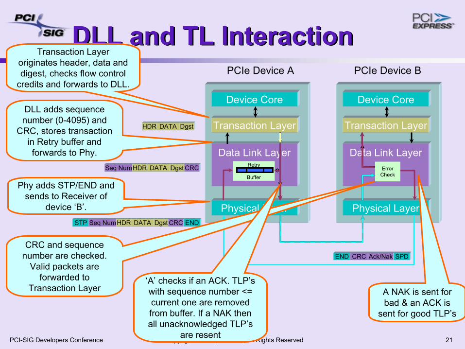
DLL and TL InteractionDLL and TL Interaction
Device Core
Transaction Layer
Data Link Layer
Physical Layer
Device Core
Transaction Layer
Data Link Layer
Physical Layer
PCIe Device A PCIe Device B
Retry
Buffer
ErrorCheck
Transaction Layer originates header, data and digest, checks flow control
credits and forwards to DLL.
HDR DATA Dgst
DLL adds sequence number (0-4095) and
CRC, stores transaction in Retry buffer and forwards to Phy.
Seq NumHDR DATA Dgst CRC
Phy adds STP/END and sends to Receiver of
device ‘B’.STP Seq NumHDR DATA Dgst CRC END
A NAK is sent for bad & an ACK is
sent for good TLP’s
CRC and sequence number are checked.
Valid packets are forwarded to
Transaction Layer
END CRC Ack/Nak SPD
‘A’ checks if an ACK. TLP’s with sequence number <= current one are removed from buffer. If a NAK then all unacknowledged TLP’s
are resent
Copyright © 2004, PCI-SIG, All Rights Reserved 22PCI-SIG Developers Conference
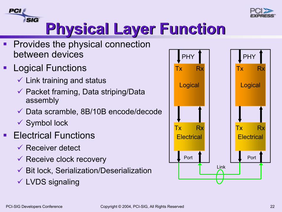
Physical Layer FunctionPhysical Layer FunctionProvides the physical connection between devicesLogical Functions
Link training and statusPacket framing, Data striping/Data assemblyData scramble, 8B/10B encode/decodeSymbol lock
Electrical FunctionsReceiver detectReceive clock recoveryBit lock, Serialization/DeserializationLVDS signaling
Logical
Electrical
PHY
Tx Rx
Tx Rx
Logical
Electrical
PHY
Tx Rx
Tx Rx
Link
Port Port
Copyright © 2004, PCI-SIG, All Rights Reserved 23PCI-SIG Developers Conference
AgendaAgenda
PCI Express Overview, Components & Architecture PCI Express Protocol LayersNeeds of Communication Systems & PCIePCI Express in Communication SystemsSummary
Copyright © 2004, PCI-SIG, All Rights Reserved 24PCI-SIG Developers Conference
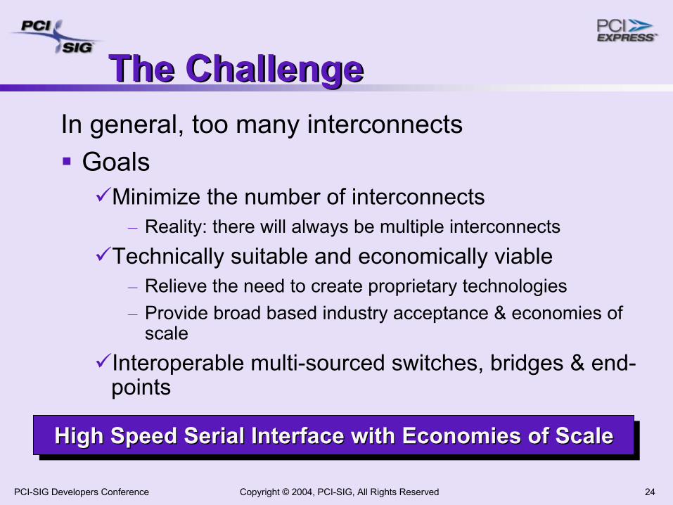
The ChallengeThe ChallengeIn general, too many interconnects
GoalsMinimize the number of interconnects
– Reality: there will always be multiple interconnectsTechnically suitable and economically viable
– Relieve the need to create proprietary technologies– Provide broad based industry acceptance & economies of
scaleInteroperable multi-sourced switches, bridges & end-points
High Speed Serial Interface with Economies of ScaleHigh Speed Serial Interface with Economies of ScaleHigh Speed Serial Interface with Economies of Scale
Copyright © 2004, PCI-SIG, All Rights Reserved 25PCI-SIG Developers Conference
Functional NeedsFunctional Needs
Connectivity, Bandwidth and Scalability Data Integrity and ReliabilityServiceability and AvailabilityQuality of Service
Copyright © 2004, PCI-SIG, All Rights Reserved 26PCI-SIG Developers Conference
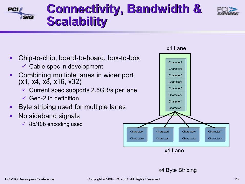
Connectivity, Bandwidth & Scalability Connectivity, Bandwidth & Scalability
Chip-to-chip, board-to-board, box-to-boxCable spec in development
Combining multiple lanes in wider port (x1, x4, x8, x16, x32)
Current spec supports 2.5GB/s per laneGen-2 in definition
Byte striping used for multiple lanesNo sideband signals
8b/10b encoding used
Character0
Character0 Character1 Character2 Character3
Character1
Character2
Character3
Character4
Character5
Character6
Character7
Character4 Character5 Character6 Character7
x1 Lane
x4 Lane
x4 Byte Striping
Copyright © 2004, PCI-SIG, All Rights Reserved 27PCI-SIG Developers Conference
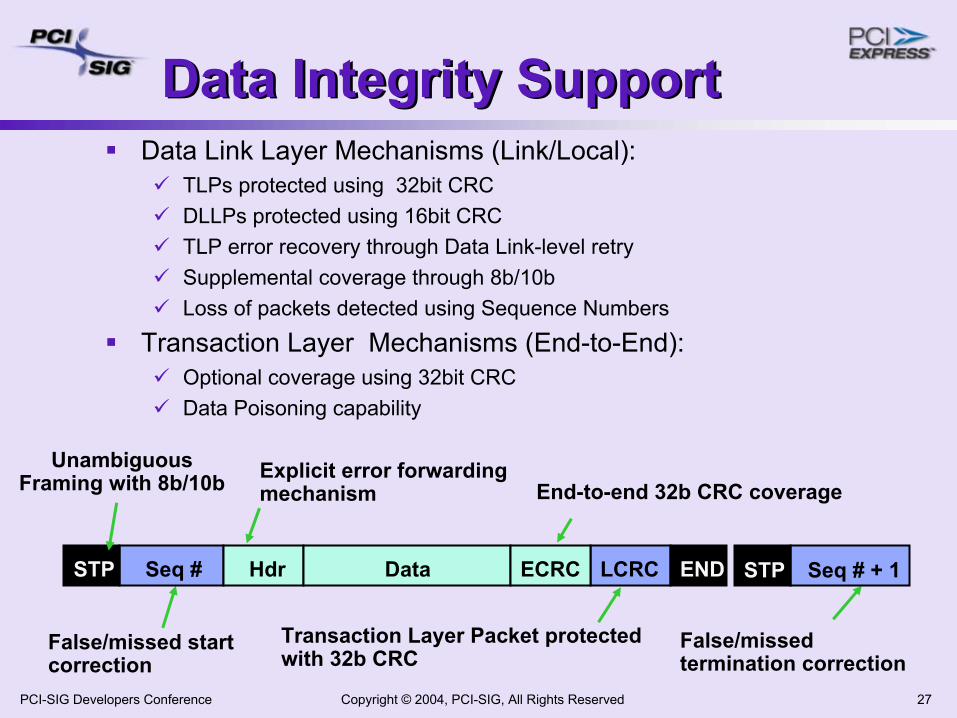
Data Integrity SupportData Integrity SupportData Link Layer Mechanisms (Link/Local):
TLPs protected using 32bit CRCDLLPs protected using 16bit CRCTLP error recovery through Data Link-level retrySupplemental coverage through 8b/10bLoss of packets detected using Sequence Numbers
Transaction Layer Mechanisms (End-to-End):Optional coverage using 32bit CRCData Poisoning capability
False/missed start correction
False/missed termination correction
LCRCSeq #
End-to-end 32b CRC coverage
Transaction Layer Packet protected with 32b CRC
END Seq # + 1STPHdr Data ECRC
Explicit error forwarding mechanism
STP
Unambiguous Framing with 8b/10b
Copyright © 2004, PCI-SIG, All Rights Reserved 28PCI-SIG Developers Conference
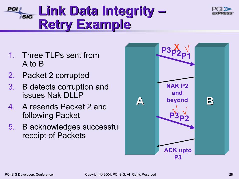
Link Data Integrity –Retry ExampleLink Data Integrity –Retry Example
1. Three TLPs sent fromA to B
2. Packet 2 corrupted3. B detects corruption and
issues Nak DLLP4. A resends Packet 2 and
following Packet5. B acknowledges successful
receipt of Packets
AA
P1P2P3 X
NAK P2 and
beyond
P2P3
ACK upto P3
BB
√
√√
Copyright © 2004, PCI-SIG, All Rights Reserved 29PCI-SIG Developers Conference
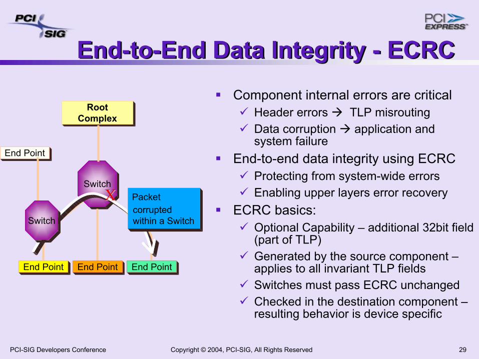
End-to-End Data Integrity - ECRCEnd-to-End Data Integrity - ECRCComponent internal errors are critical
Header errors TLP misroutingData corruption application and system failure
End-to-end data integrity using ECRCProtecting from system-wide errorsEnabling upper layers error recovery
ECRC basics: Optional Capability – additional 32bit field (part of TLP)Generated by the source component –applies to all invariant TLP fieldsSwitches must pass ECRC unchangedChecked in the destination component –resulting behavior is device specific
End Point
Switch
End PointEnd Point End Point
RootComplex
X X Packet corruptedwithin a SwitchSwitch
Copyright © 2004, PCI-SIG, All Rights Reserved 30PCI-SIG Developers Conference
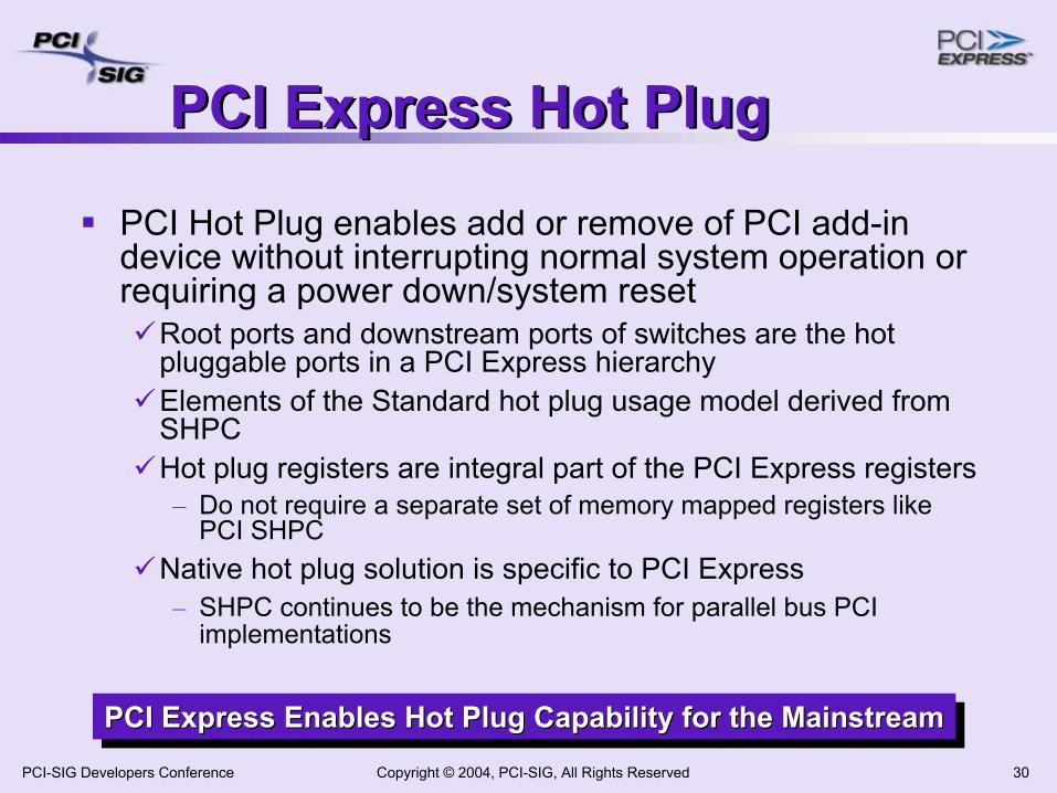
PCI Express Hot PlugPCI Express Hot Plug
PCI Hot Plug enables add or remove of PCI add-in device without interrupting normal system operation or requiring a power down/system reset
Root ports and downstream ports of switches are the hot pluggable ports in a PCI Express hierarchyElements of the Standard hot plug usage model derived from SHPCHot plug registers are integral part of the PCI Express registers
– Do not require a separate set of memory mapped registers like PCI SHPC
Native hot plug solution is specific to PCI Express– SHPC continues to be the mechanism for parallel bus PCI
implementations
PCI Express Enables Hot Plug Capability for the MainstreamPCI Express Enables Hot Plug Capability for the MainstreamPCI Express Enables Hot Plug Capability for the Mainstream
Copyright © 2004, PCI-SIG, All Rights Reserved 31PCI-SIG Developers Conference
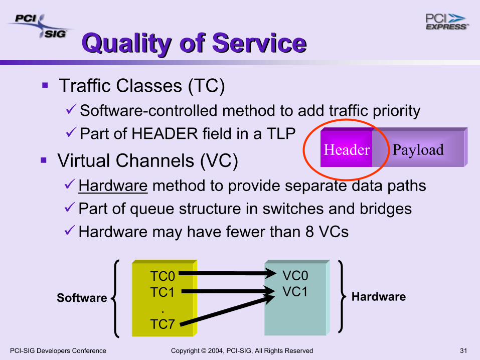
Quality of ServiceQuality of ServiceTraffic Classes (TC)
Software-controlled method to add traffic priorityPart of HEADER field in a TLP
Header PayloadVirtual Channels (VC)Hardware method to provide separate data pathsPart of queue structure in switches and bridgesHardware may have fewer than 8 VCs
TC0TC1
.TC7
Software
VC0VC1 Hardware
Copyright © 2004, PCI-SIG, All Rights Reserved 32PCI-SIG Developers Conference
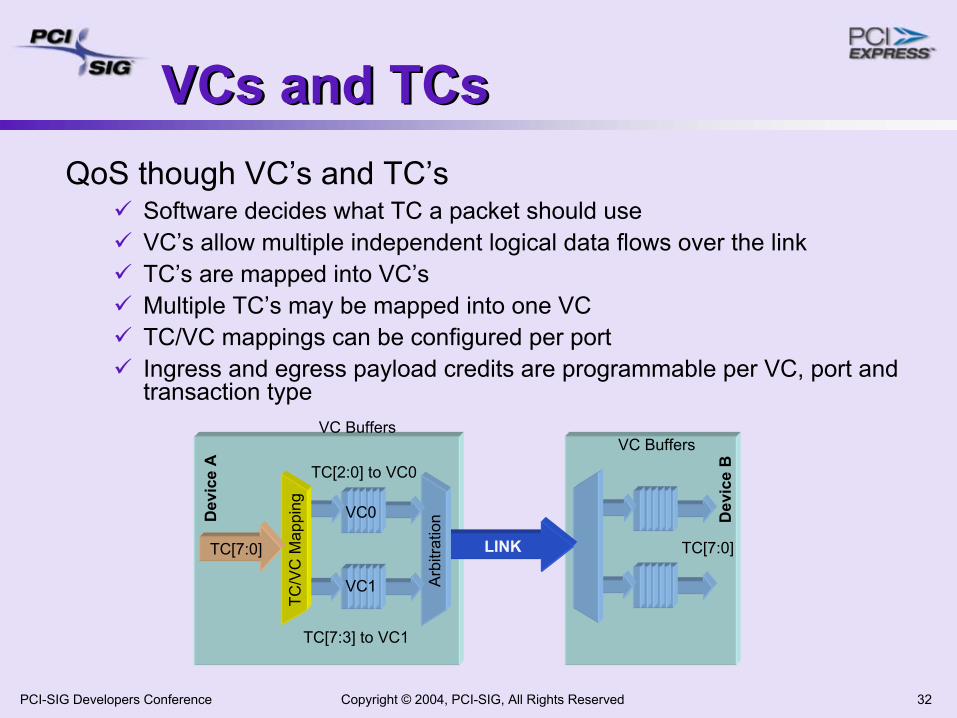
VCs and TCsVCs and TCsQoS though VC’s and TC’s
Software decides what TC a packet should useVC’s allow multiple independent logical data flows over the link TC’s are mapped into VC’sMultiple TC’s may be mapped into one VCTC/VC mappings can be configured per portIngress and egress payload credits are programmable per VC, port and transaction type
LINK
Arb
itrat
ion
TC/V
C M
appi
ng
TC[7:0]
Dev
ice
A
Dev
ice
B
VC0
VC1
VC Buffers
TC[2:0] to VC0
TC[7:3] to VC1
VC Buffers
TC[7:0]
Copyright © 2004, PCI-SIG, All Rights Reserved 33PCI-SIG Developers Conference
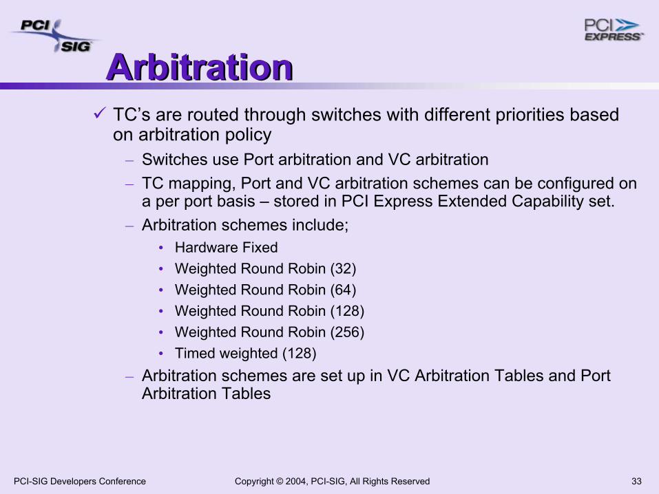
ArbitrationArbitrationTC’s are routed through switches with different priorities based on arbitration policy
– Switches use Port arbitration and VC arbitration– TC mapping, Port and VC arbitration schemes can be configured on
a per port basis – stored in PCI Express Extended Capability set.– Arbitration schemes include;
• Hardware Fixed• Weighted Round Robin (32)• Weighted Round Robin (64)• Weighted Round Robin (128)• Weighted Round Robin (256)• Timed weighted (128)
– Arbitration schemes are set up in VC Arbitration Tables and PortArbitration Tables
Copyright © 2004, PCI-SIG, All Rights Reserved 34PCI-SIG Developers Conference
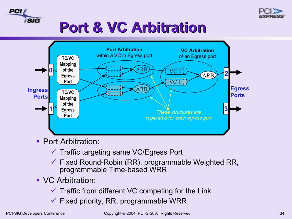
Port & VC ArbitrationPort & VC Arbitration
Port Arbitration: Traffic targeting same VC/Egress PortFixed Round-Robin (RR), programmable Weighted RR, programmable Time-based WRR
VC Arbitration: Traffic from different VC competing for the LinkFixed priority, RR, programmable WRR
Port Arbitrationwithin a VC in Egress port
VC Arbitrationof an Egress port
ARBVC 1
VC 0ARB
ARB
These structures arereplicated for each egress port
TC/VCMapping
of theEgress
Port
TC/VCMapping
of theEgress
Port3
IngressPorts
EgressPorts
20
1
Copyright © 2004, PCI-SIG, All Rights Reserved 35PCI-SIG Developers Conference
AgendaAgenda
PCI Express Overview, Components & Architecture PCI Express Protocol LayersNeeds of Communication Systems & PCIePCI Express in Communication SystemsSummary
Copyright © 2004, PCI-SIG, All Rights Reserved 36PCI-SIG Developers Conference
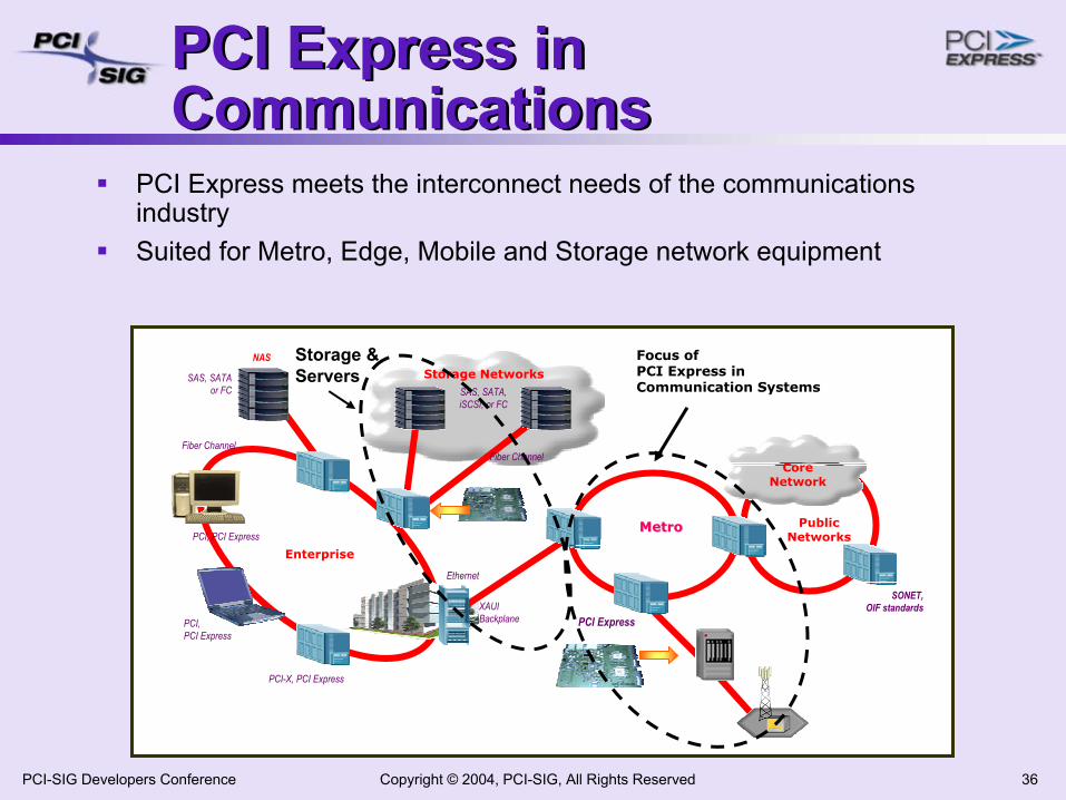
PCI Express in CommunicationsPCI Express in Communications
PCI Express meets the interconnect needs of the communications industrySuited for Metro, Edge, Mobile and Storage network equipment
CoreNetwork
PublicNetworks
Enterprise
Storage Networks
Fiber Channel Fiber Channel
SAS, SATA,iSCSI, or FC
SAS, SATAor FC
PCI, PCI Express
PCI,PCI Express
PCI-X, PCI Express
NAS
SONET,OIF standards XAUI
Backplane
Ethernet
MetroMetro
PCI Express
Focus ofPCI Express inCommunication Systems
Storage & Servers
Copyright © 2004, PCI-SIG, All Rights Reserved 37PCI-SIG Developers Conference
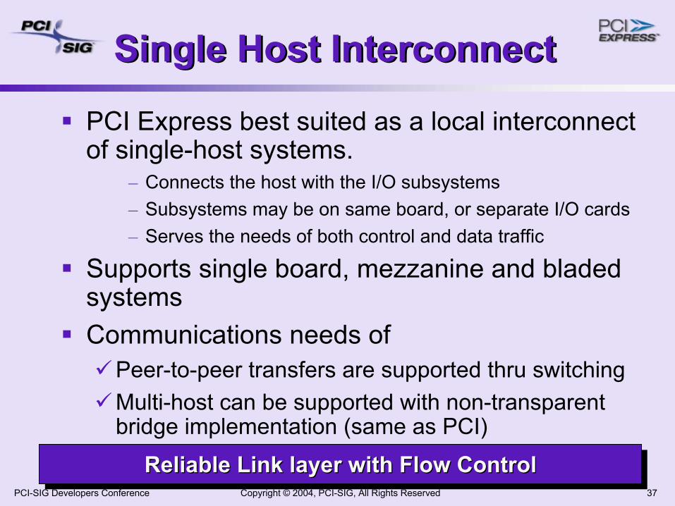
Single Host InterconnectSingle Host Interconnect
PCI Express best suited as a local interconnect of single-host systems.
– Connects the host with the I/O subsystems– Subsystems may be on same board, or separate I/O cards– Serves the needs of both control and data traffic
Supports single board, mezzanine and bladed systemsCommunications needs of
Peer-to-peer transfers are supported thru switchingMulti-host can be supported with non-transparent bridge implementation (same as PCI)
Reliable Link layer with Flow ControlReliable Link layer with Flow ControlReliable Link layer with Flow Control
Copyright © 2004, PCI-SIG, All Rights Reserved 38PCI-SIG Developers Conference
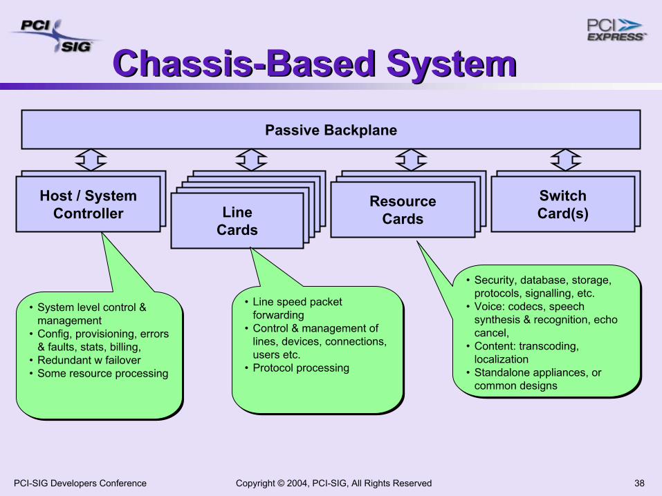
Chassis-Based SystemChassis-Based System
Host / System Controller
LineCards
SwitchCard(s)
ResourceCards
Passive Backplane
Host / System Controller
LineCardsLine
CardsLine
CardsLine
Cards
ResourceCards
ResourceCards
SwitchCard(s)
• Security, database, storage, protocols, signalling, etc.
• Voice: codecs, speech synthesis & recognition, echo cancel,
• Content: transcoding, localization
• Standalone appliances, or common designs
• Security, database, storage, protocols, signalling, etc.
• Voice: codecs, speech synthesis & recognition, echo cancel,
• Content: transcoding, localization
• Standalone appliances, or common designs
• Line speed packet forwarding
• Control & management of lines, devices, connections, users etc.
• Protocol processing
• Line speed packet forwarding
• Control & management of lines, devices, connections, users etc.
• Protocol processing
• System level control & management
• Config, provisioning, errors & faults, stats, billing,
• Redundant w failover• Some resource processing
• System level control & management
• Config, provisioning, errors & faults, stats, billing,
• Redundant w failover• Some resource processing
Copyright © 2004, PCI-SIG, All Rights Reserved 39PCI-SIG Developers Conference
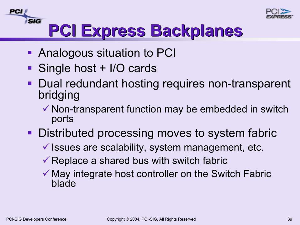
PCI Express BackplanesPCI Express BackplanesAnalogous situation to PCISingle host + I/O cardsDual redundant hosting requires non-transparent bridging
Non-transparent function may be embedded in switch ports
Distributed processing moves to system fabric Issues are scalability, system management, etc.Replace a shared bus with switch fabricMay integrate host controller on the Switch Fabric blade
Copyright © 2004, PCI-SIG, All Rights Reserved 40PCI-SIG Developers Conference
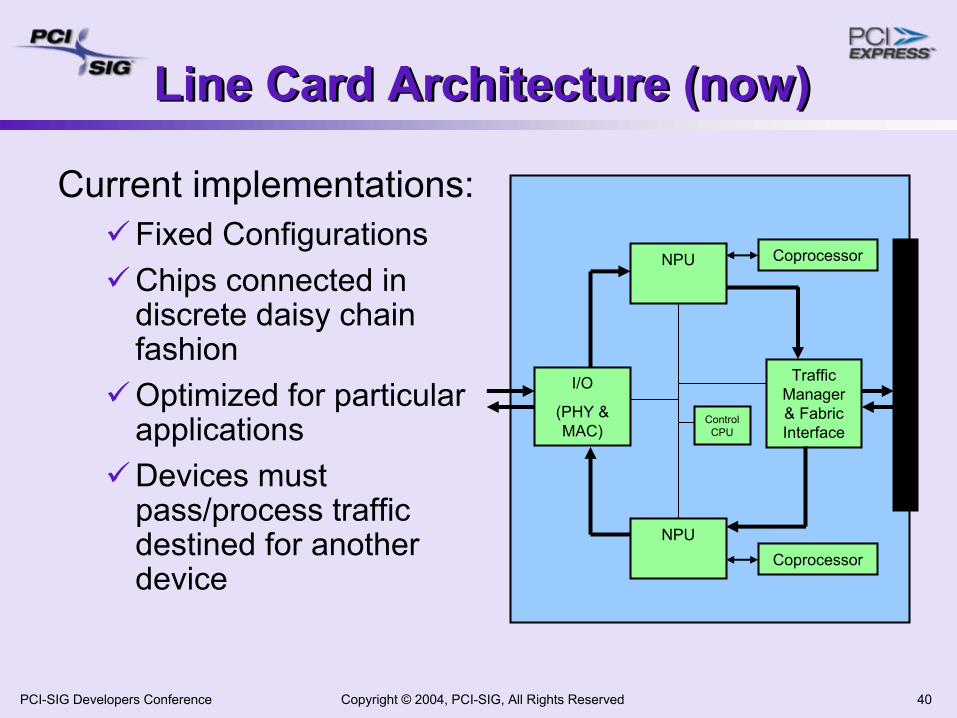
Line Card Architecture (now)Line Card Architecture (now)
Current implementations:Fixed Configurations Chips connected in discrete daisy chain fashionOptimized for particular applicationsDevices must pass/process traffic destined for another device
I/O
(PHY & MAC)
Traffic Manager & Fabric Interface
NPUCoprocessor
CoprocessorNPU
Control CPU
Copyright © 2004, PCI-SIG, All Rights Reserved 41PCI-SIG Developers Conference
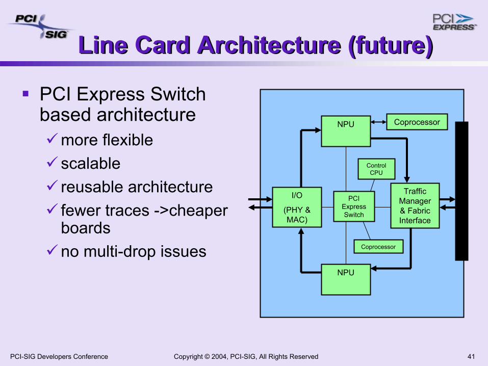
Line Card Architecture (future)Line Card Architecture (future)
PCI Express Switch based architecture
more flexiblescalablereusable architecturefewer traces ->cheaper boardsno multi-drop issues
I/O
(PHY & MAC)
Traffic Manager & Fabric Interface
NPU
Coprocessor
CoprocessorNPU
Control CPU
PCI Express Switch
Copyright © 2004, PCI-SIG, All Rights Reserved 42PCI-SIG Developers Conference
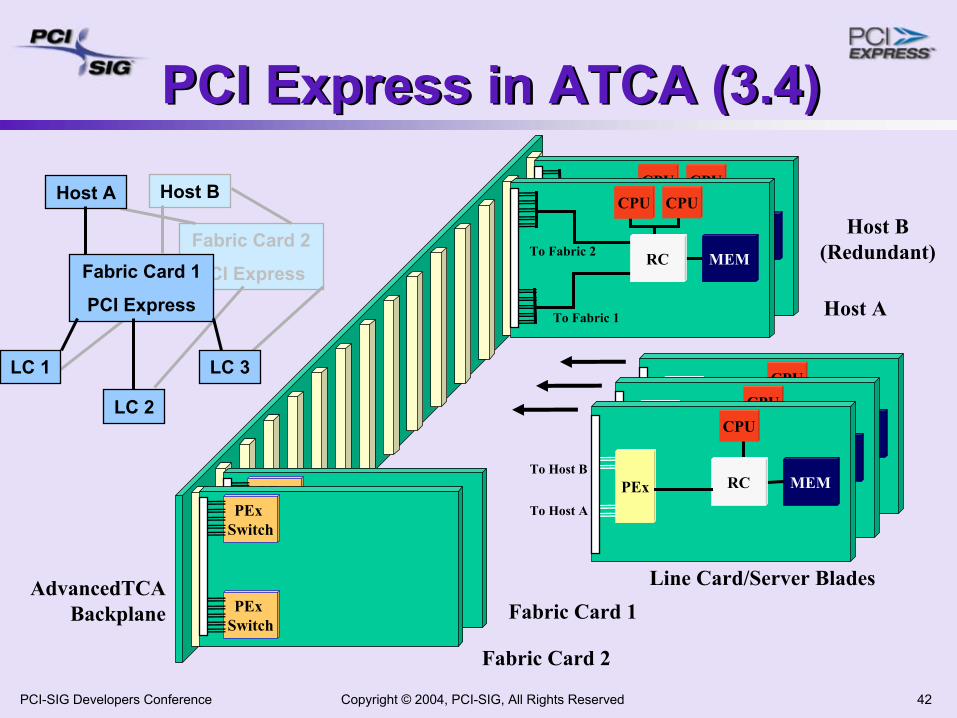
PCI Express in ATCA (3.4)PCI Express in ATCA (3.4)
Host A
Host B (Redundant)
MEM
CPU
EPMCHPCIX
1GE1GE
MEM
CPU
EPMCHPCIX
1GE1GETo Host A
To Host BMEM
CPU
PEx RC
Line Card/Server BladesAdvancedTCA Backplane
PEx Switch
PEx Switch
To Fabric B
To Fabric A
PEx Switch
PEx Switch
Fabric Card 2
Fabric Card 1
MEMRC
CPU CPU
To Fabric 1
To Fabric 2
MEMRC
CPU CPU
To Fabric 1
To Fabric 2Fabric Card 2
PCI Express
Host A Host B
LC 1
LC 2
LC 3
Fabric Card 1
PCI Express
Copyright © 2004, PCI-SIG, All Rights Reserved 43PCI-SIG Developers Conference
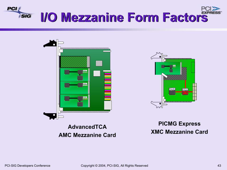
I/O Mezzanine Form FactorsI/O Mezzanine Form Factors
P--PCI-XDevice
P--PCI-XDevice
P--PCI-XDevice
AdvancedTCAAMC Mezzanine Card
P--PCI-X
PICMG ExpressXMC Mezzanine Card
Copyright © 2004, PCI-SIG, All Rights Reserved 44PCI-SIG Developers Conference
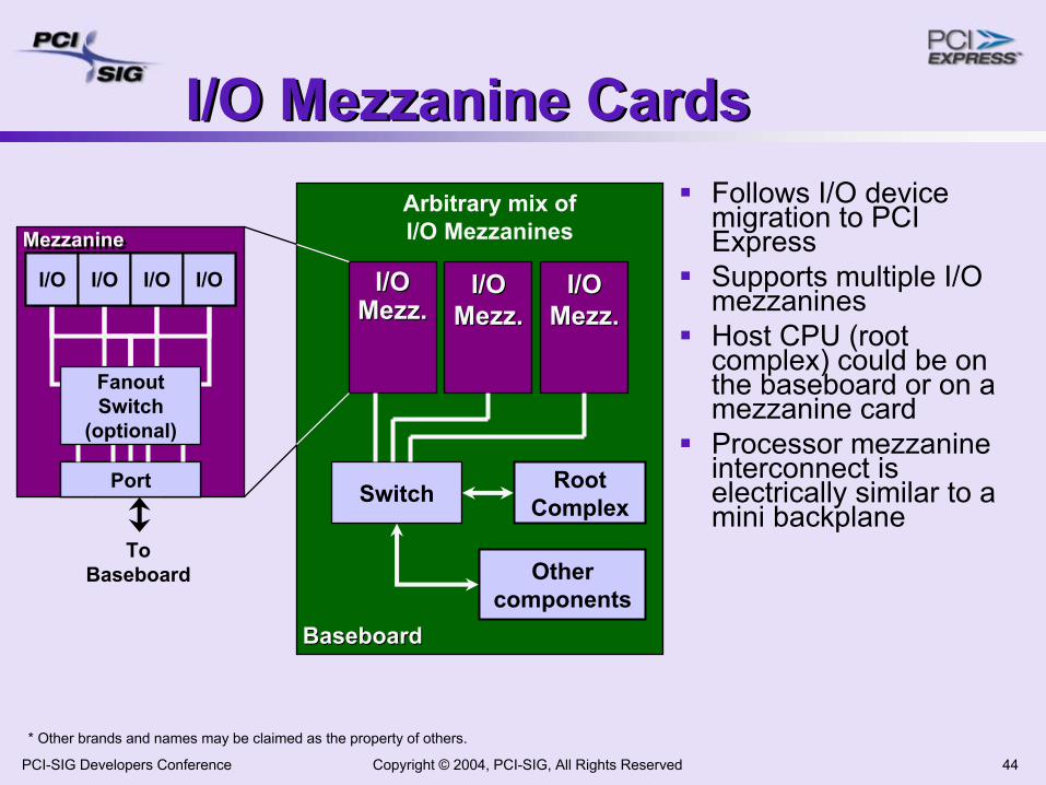
ToBaseboard
MezzanineMezzanine
I/O Mezzanine CardsI/O Mezzanine Cards
* Other brands and names may be claimed as the property of others.
Follows I/O device migration to PCI ExpressSupports multiple I/O mezzaninesHost CPU (root complex) could be on the baseboard or on a mezzanine cardProcessor mezzanine interconnect is electrically similar to a mini backplane
BaseboardBaseboard
I/OI/OMezz.Mezz.
Switch
Arbitrary mix ofI/O Mezzanines
I/OI/OMezz.Mezz.
I/OI/OMezz.Mezz.
RootComplex
Othercomponents
Port(s)
I/O I/O I/O I/O
Port
I/O I/O I/O I/O
Fanout Switch
(optional)
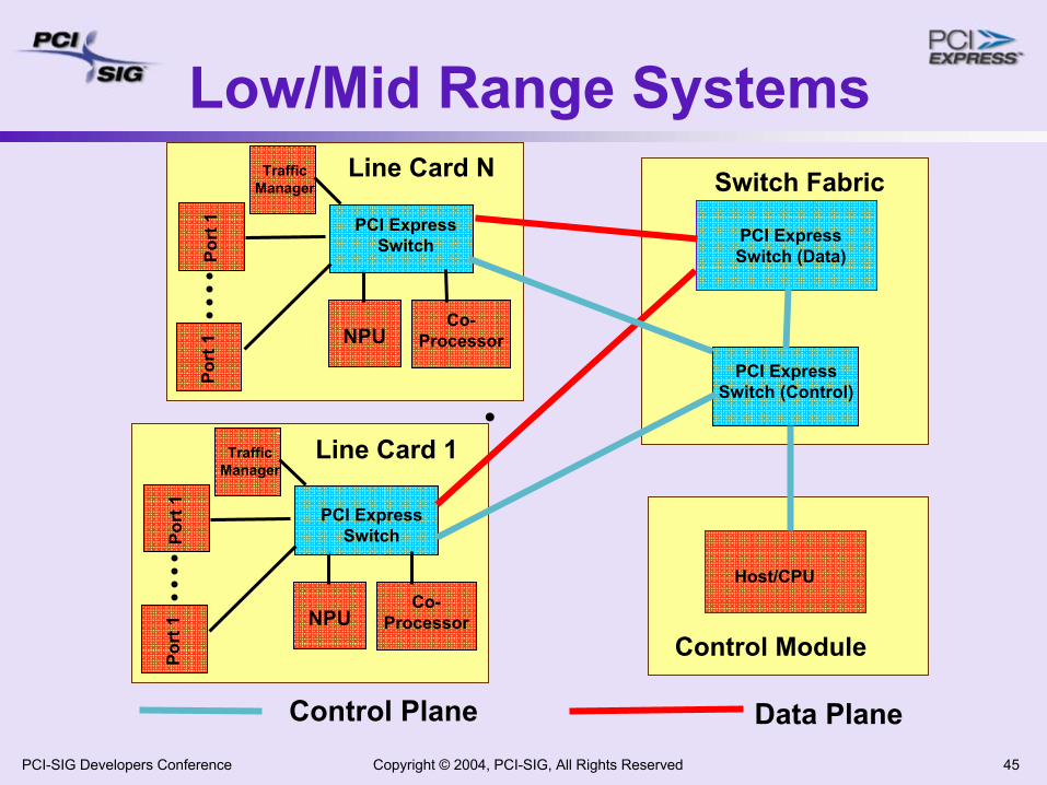
Copyright © 2004, PCI-SIG, All Rights Reserved 45PCI-SIG Developers Conference
Switch Fabric
Control Module
Host/CPU
Control Plane Data Plane
Port
1
Line Card 1
NPUCo-
Processor
Port
1
Traffic Manager
Port
1
Line Card N
PCI Express Switch
NPUCo-
Processor
Port
1
Traffic Manager
Low/Mid Range Systems
PCI Express Switch
PCI Express Switch (Data)
PCI Express Switch (Control)
Copyright © 2004, PCI-SIG, All Rights Reserved 46PCI-SIG Developers Conference
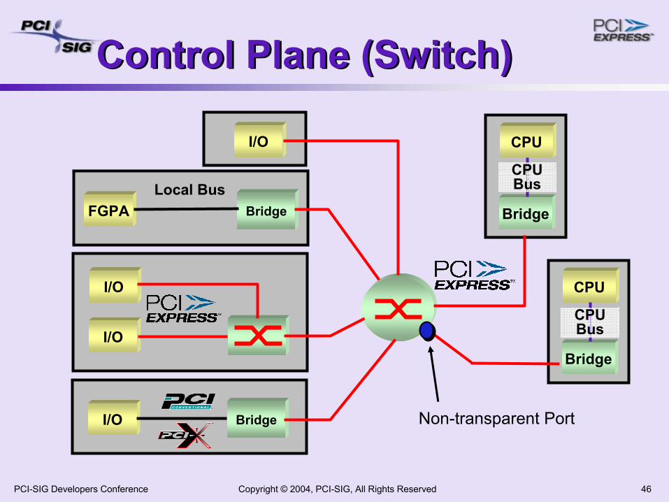
Control Plane (Switch) Control Plane (Switch)
I/O
I/O Bridge
I/O
I/O
FGPA BridgeLocal Bus
CPU
Bridge
CPUBus
CPU
Bridge
CPUBus
Non-transparent Port
Copyright © 2004, PCI-SIG, All Rights Reserved 47PCI-SIG Developers Conference
AgendaAgenda
PCI Express Overview, Components & Architecture PCI Express Protocol LayersNeeds of Communication Systems & PCIePCI Express in Communication SystemsSummary
Copyright © 2004, PCI-SIG, All Rights Reserved 48PCI-SIG Developers Conference
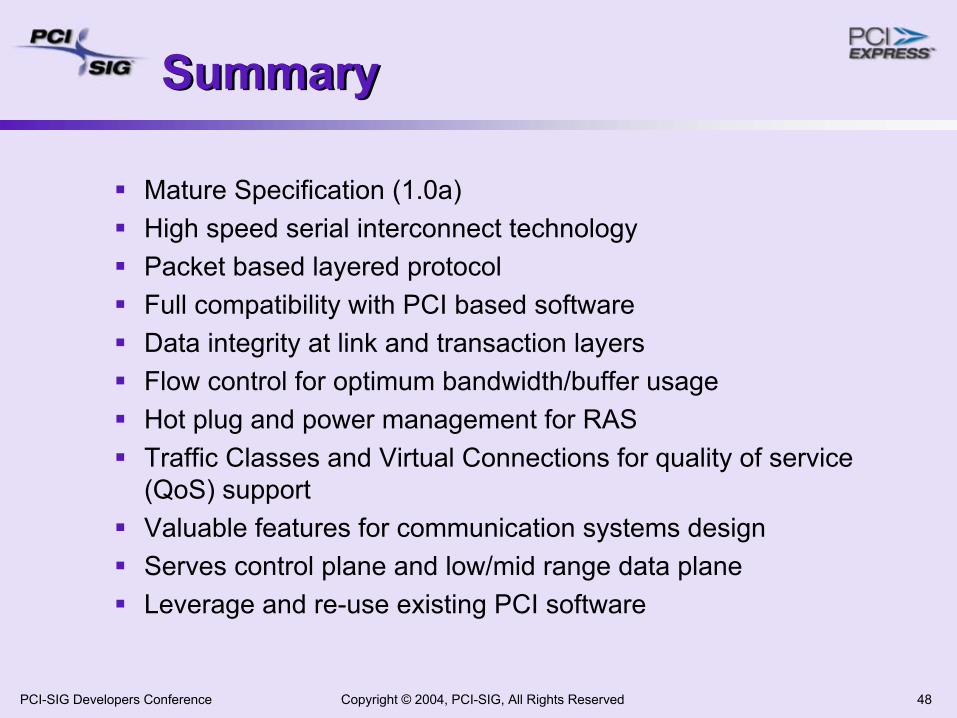
SummarySummary
Mature Specification (1.0a)High speed serial interconnect technologyPacket based layered protocolFull compatibility with PCI based softwareData integrity at link and transaction layersFlow control for optimum bandwidth/buffer usageHot plug and power management for RASTraffic Classes and Virtual Connections for quality of service (QoS) supportValuable features for communication systems designServes control plane and low/mid range data planeLeverage and re-use existing PCI software
Copyright © 2004, PCI-SIG, All Rights Reserved 49PCI-SIG Developers Conference
Thank you for attending the PCI-SIG Developers Conference 2004.
For more information please go to www.pcisig.com
Copyright © 2004, PCI-SIG, All Rights Reserved 50PCI-SIG Developers Conference


