Performance Evaluation of the Hilbert Transform Based Digital Phase-Locked Loop Ivica Kopriva and Dragan Juricic Institute for Defense Studies, R&D, Bijenicka 46, 10000 Zagreb, Croatia e-mail: [email protected], [email protected]Abstract Multiplier free Digital Phase-Locked Loop ( DPLL) based on Hilbert transform has been analyzed in this paper. The performance of this DPLL when applied as FM demodulator is evaluated in relation to the DPLL with Multiplier based Phase Detector (MPD) showing better dynamic properties expressed in the form of the lock range, settling time, pull-out range etc. 1. Introduction In the field of communication, the phase-locked loop (PLL) is frequently used for frequency demodulation [1],[2]. In analog PLL and appropriate variant of the DPLL, the analog and digital multipliers are used as Phase Detectors (PD). The MPD measures the phase difference between the input and output signals and produces an error signal proportional to the measured phase difference. The output signal of the MPD consists of a DC component ( phase difference) and an unwanted AC component (high frequency component ). The Low Pass (LP) filter in the loop removes the AC component of the MPD. The loop filter transfer function has an important influence on the dynamic performance of the loop. If we want to use the PLL to demodulate frequency modulation the loop filter must be wide enough to obtain best loop tracking and acquisition properties, or the loop bandwidth should be made as large as possible to minimize phase error. Simultaneously, the loop filter should reject undesired high frequency component of the MPD and it must be chosen as LP filter. It can be shown that if cuttoff frequency of the loop filter is too low and the frequency deviation of the input FM signal is excessive, the PLL can lose lock. Actually, there is a conflict in design of the loop filter and desired dynamic features of the PLL [3]. 2. Hilbert transform PD The Hilbert Transform based Phase Detector ( HTPD), which employs quadrature signal processing method [4], estimates phase difference between input and output signals without using LP filter: Figure 1: HTPD operating principle This PD extracts the phase error between the input ) ( 1 n u and output ) ( 2 n u signals of the PLL by complex multiplication of complex signals [5],[6],[7]. A complex signal of the form ) ( ~ ) ( n u j n u ± is synthesized from a real signal ) ( n u and its Hilbert Transform and is known as an analytic signal. The input and output analytic signals of the PLL are defined by: X ( . )+jH{ .} ( . )-jH{ .} Im{ . } u 1 (n) u d (n) u 2 (n)
Transcript
Performance Evaluation of the Hilbert Transform BasedDigital Phase-Locked Loop
Ivica Kopriva and Dragan JuricicInstitute for Defense Studies, R&D, Bijenicka 46, 10000 Zagreb, Croatia
Multiplier free Digital Phase-LockedLoop (DPLL) based on Hilbert transform hasbeen analyzed in this paper. The performanceof this DPLL when applied as FM demodulatoris evaluated in relation to the DPLL withMultiplier based Phase Detector (MPD)showing better dynamic properties expressed inthe form of the lock range, settling time, pull-outrange etc.
1. Introduction
In the field of communication, thephase-locked loop (PLL) is frequently used forfrequency demodulation [1],[2]. In analog PLLand appropriate variant of the DPLL, theanalog and digital multipliers are used as PhaseDetectors (PD). The MPD measures the phasedifference between the input and output signalsand produces an error signal proportional to themeasured phase difference. The output signal ofthe MPD consists of a DC component (phasedifference) and an unwanted AC component(high frequency component). The Low Pass(LP) filter in the loop removes the ACcomponent of the MPD. The loop filter transferfunction has an important influence on thedynamic performance of the loop. If we want touse the PLL to demodulate frequencymodulation the loop filter must be wide enoughto obtain best loop tracking and acquisitionproperties, or the loop bandwidth should bemade as large as possible to minimize phase
error. Simultaneously, the loop filter shouldreject undesired high frequency component ofthe MPD and it must be chosen as LP filter. Itcan be shown that if cuttoff frequency of theloop filter is too low and the frequencydeviation of the input FM signal is excessive,the PLL can lose lock. Actually, there is aconflict in design of the loop filter and desireddynamic features of the PLL [3].
2. Hilbert transform PD
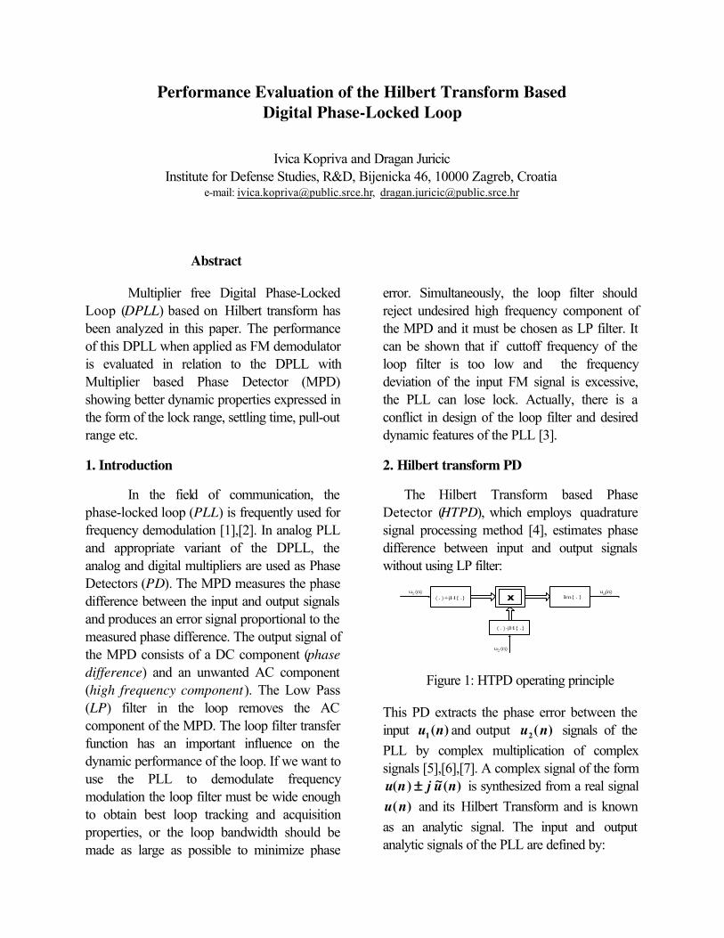
The Hilbert Transform based PhaseDetector (HTPD), which employs quadraturesignal processing method [4], estimates phasedifference between input and output signalswithout using LP filter:
Figure 1: HTPD operating principle
This PD extracts the phase error between theinput )(1 nu and output )(2 nu signals of thePLL by complex multiplication of complexsignals [5],[6],[7]. A complex signal of the form
)(~)( nujnu ±± is synthesized from a real signal)(nu and its Hilbert Transform and is known
as an analytic signal. The input and outputanalytic signals of the PLL are defined by:
X( . )+jH{ .}
( . )-jH{ .}
Im{ . }u1(n) ud(n)
u2(n)
[ ]
[ ])(2222
)(1111
20
10
)(ˆ)()(
)(ˆ)()(nnj
nnj
eAnujnunU
eAnujnunUϕω
ϕω
+
+
=−=
=+= (1)
The complex multiplication of these analyticsignals produces an output analytic signal of thePD. The real signal of the PD can be obtainedby taking imaginary part of this analytic signal:
[ ]{ }[ ] [ ])(sin)()(sin
)(
212121
)()(21
21
nAAnnAAeAAIMnu
e
nnjd
ϕϕϕ
ϕϕ
=−=== −
(2)
It can be seen that the output signal of theHTPD )(nud consists of a DC component and
does not contain the unwanted AC component.Consequently, there is no need for using a LPfilter as a PLL component building block. Thedigital controlled oscillator (DCO) used in thistype of PLL generates two signals, an in-phasesignal I and a quadrature signal Q. The DCO isnot able to compute I and Q signals directly.These signal are calculated indirectly from thephase )(2 nφφ . I signal and Q signals are theHilbert-transform pair. The signal flow diagramfor this DPLL is illustrated in Fig. 2.
F I R H T x
x
-1
D C O
+u
1(n)
I Q
2
1−−
M
z
Waveformsynthesizer θ2(n) 1
0
−z
TK
ud(n)
PD
Figure 2. The digital PLL with HTPD
As indicated in the block diagram, this type ofDPLL is a first-order loop because the loopfilter is omitted. The loop delays input signal by(M-1)/2 time steps and the output signal ofHTPD directly controls the DCO.
3. Performance analysis
Performance of the DPLL with HTPDis compared with the DPLL with MPD throughevaluation of the four key parameters specifyingfrequency range in which PLL can be operated.The loop filter has an important influence onthese parameters. They are defined for bothvariants of the loop as:
Digital PLL withLP filter
DigitalPLL with
HTPD
The hold range
( Hωω∆∆ )∞→)0(HKK do do KK
The lock range
( Lωω∆∆ )ξω
τ
τn
do KK2
1
2 = do KK
The pull-outrange
( POωω∆∆ )
)1(8.1 +≈ ξω n do KK
The pull-in
range ( Pωω∆∆ )∞→
do KK
where nωω is the loop natural frequency, dK is
gain of PD and 0K is gain of the VCO. If, the
PLL is pulled-out by a large frequency step, wecan expect that PLL to come back to stableoperation. This process is known as pull-inprocess and is relatively slow. The frequencystep which causes loop to lose lock, is muchgreater for the PLL with HTPD than the PLLwith MPD. The DPLL with HTPD has largerlock range than a DPLL with MPD and is ableto track faster phase and frequency variationsof the input signal. Moreover, the loopbandwidth for the DPLL with HTPD is greaterthan the DPLL with MPD as follow:
The loopbandwidth
DPLL with LPfilter
DPLLwith
HTPD
gωω1ττ
ωωωω dong
KK==≈≈dog KK≈≈ωω
It is clear that the loop filter reduces the loopbandwidth. Consequently, the lock-in time(settling time) for the PLL with HTPD is veryshort.
One of the main advantages of using thePLL is its ability to demodulate and track signalin noise. The PLL offers excellent noiseimmunity compared to other designs [8],[9].When noise is superimposed on input signalloop bandwidth must be as narrow as possibleto minimize output phase jitter. Whereas, theloop bandwidth should be made as large aspossible to obtain best tracking and acquisitionproperties [1]. Than, there is a problem whenwe try to choose appropriate parameters of theloop. The output signal-to-noise ratio outSNR
versus the input signal-to-noise ratio inSNR
curve characterizes the PLL FM demodulatorperformance in the presence of noise. Tocalculate the signal-to-noise ratio of the VCOoutput outSNR , it is necessary to know the
inSNR , the noise bandwidth of the loop LB
and the input noise bandwidth iB as follow [3]:
inL
iout SNR
BB
SNR == (3)
If the input bandpass filter is considered as apart of the PLL FM demodulator the noisebandwidth iB is the bandwidth of such a filter.
The noise bandwidth of the loop for both typesof the PLL design is defined as [3],[10]:
Digital PLL withLP filter
Digital PLLwith HTPD
The loopbandwidth
[Hz ]
++==
ζζζζ
ωω41
2n
LB4
odL
KKB ==
The PLL with HTPD has larger noisebandwidth of the loop than digital PLL withmultiplier PD. Thus, this PLL has less rejectionof the noise superimposed on input signal. In
practice, when PLL is used as FMdemodulator we must filter the output signal forboth variants of the PLL design. Therectangular passband postfilter with cuttofffrequency equal to the massage bandwidthshould be used [9]. Therefore, thesedemodulators have approximately equal noiseperformance when the postfilter is used.
4. Simulation results
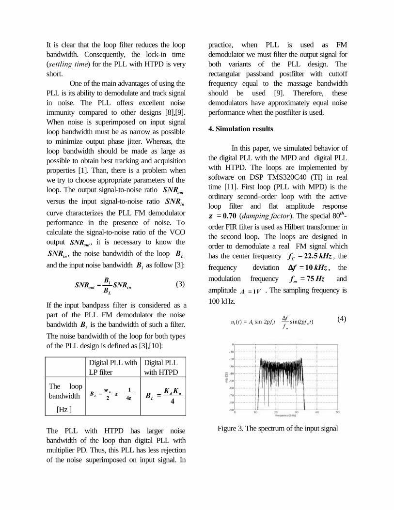
In this paper, we simulated behavior ofthe digital PLL with the MPD and digital PLLwith HTPD. The loops are implemented bysoftware on DSP TMS320C40 (TI) in realtime [11]. First loop (PLL with MPD) is theordinary second–order loop with the activeloop filter and flat amplitude response
70.0==ζζ (damping factor). The special 80th-order FIR filter is used as Hilbert transformer inthe second loop. The loops are designed inorder to demodulate a real FM signal whichhas the center frequency kHzfC 5.22== , the
frequency deviation kHzf 10==∆∆ , themodulation frequency Hzfm 75== and
amplitude VA 11 == . The sampling frequency is100 kHz.
∆+= )2sin(2sin)( 11 tf
ff
tfAtu mm
c ππ (4)
Figure 3. The spectrum of the input signal
frequency [ kHz]
mag [db]
Figure 4. The spectrum of demodulated signal (the PLL with MPD)
time [s]
voltage [V]
Figure 5. The demodulated signal
frequency [ kHz]
mag [ db]
Figure 6. The spectrum of demodulated signal (the PLL with HTPD)
time [s]
voltage [V]
Figure 7. The demodulated signal
As illustrated (Fig.6), the output signal of thePLL with HTPD does not contain the unwanted
AC component near frequency cf2 , contrary
to the digital PLL with MPD (Fig. 4). When wewant to design the digital PLL with MPD wemust choose the parameters ζζ and nωω , which
determine the frequency response and thephase error of the loop. Whereas, the phaseerror depends on frequency deviation f∆∆ andmodulation frequency mf of the input FM signal
[1]. The phase error must be small and liewithin the linear range of the loop all the time. Inthat case, demodulating signal is reproduced atthe loop output with minimum distortion [8].For greater modulation frequency which isequal to Hzfm 750== but still smaller than the
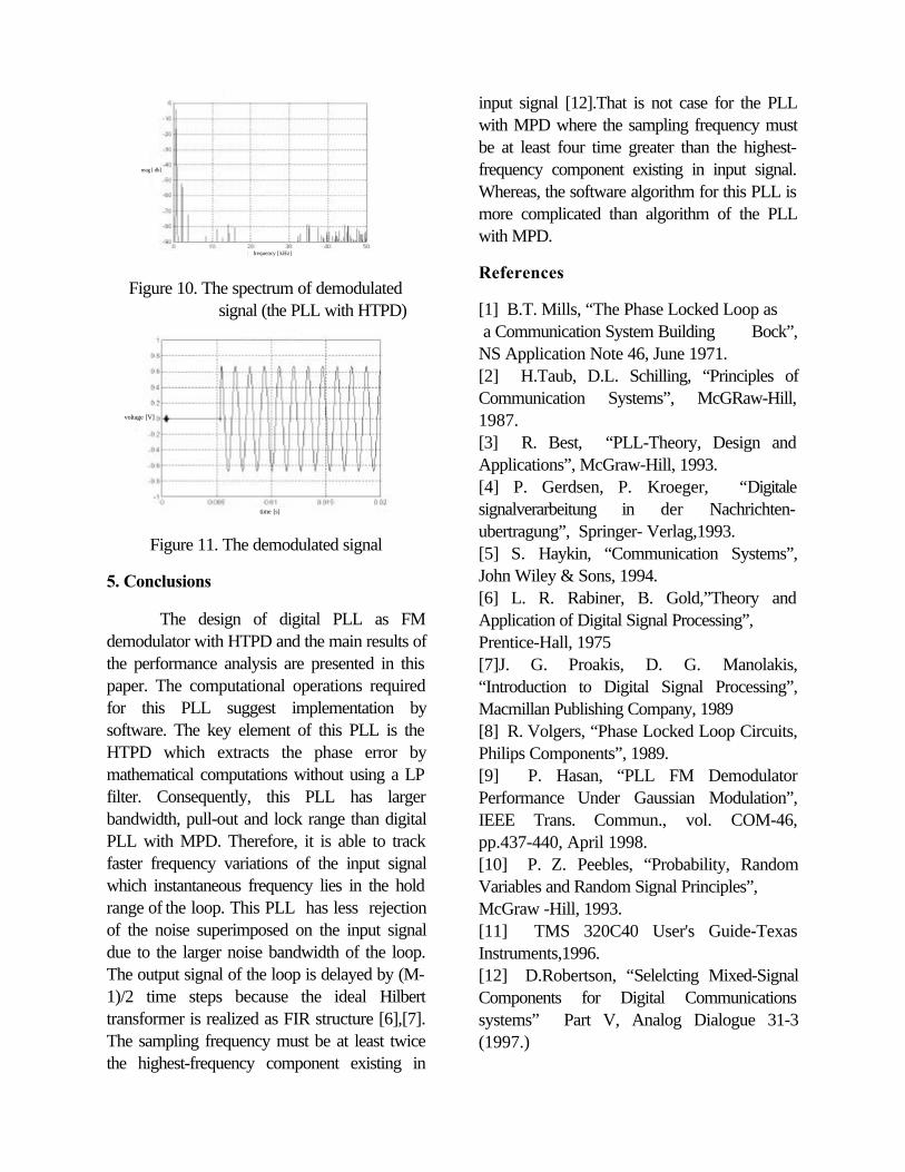
loop bandwidth, this PLL will lose lock (Fig. 8and 9). The PLL with HTPD has larger loopbandwidth and can track the new modulationfrequency of the input signal. Generally, there isno tracking problem for this PLL when theinput frequency lies in the hold range of the loop(Fig. 10 and 11).
frequency [kHz]
mag [ db]
Figure 8. The spectum of demodulated signal (the PLL with MPD)
time [s]
voltage [V]
Figure 9. The demodulated signal
frequency [ kHz]
mag [ db]
Figure 10. The spectrum of demodulated signal (the PLL with HTPD)
time [s]
voltage [V]
Figure 11. The demodulated signal
5. Conclusions
The design of digital PLL as FMdemodulator with HTPD and the main results ofthe performance analysis are presented in thispaper. The computational operations requiredfor this PLL suggest implementation bysoftware. The key element of this PLL is theHTPD which extracts the phase error bymathematical computations without using a LPfilter. Consequently, this PLL has largerbandwidth, pull-out and lock range than digitalPLL with MPD. Therefore, it is able to trackfaster frequency variations of the input signalwhich instantaneous frequency lies in the holdrange of the loop. This PLL has less rejectionof the noise superimposed on the input signaldue to the larger noise bandwidth of the loop.The output signal of the loop is delayed by (M-1)/2 time steps because the ideal Hilberttransformer is realized as FIR structure [6],[7].The sampling frequency must be at least twicethe highest-frequency component existing in
input signal [12].That is not case for the PLLwith MPD where the sampling frequency mustbe at least four time greater than the highest-frequency component existing in input signal.Whereas, the software algorithm for this PLL ismore complicated than algorithm of the PLLwith MPD.
References
[1] B.T. Mills, “The Phase Locked Loop as a Communication System Building Bock”,NS Application Note 46, June 1971.[2] H.Taub, D.L. Schilling, “Principles ofCommunication Systems”, McGRaw-Hill,1987.[3] R. Best, “PLL-Theory, Design andApplications”, McGraw-Hill, 1993.[4] P. Gerdsen, P. Kroeger, “Digitalesignalverarbeitung in der Nachrichten-ubertragung”, Springer- Verlag,1993.[5] S. Haykin, “Communication Systems”,John Wiley & Sons, 1994.[6] L. R. Rabiner, B. Gold,”Theory andApplication of Digital Signal Processing”,Prentice-Hall, 1975[7]J. G. Proakis, D. G. Manolakis,“Introduction to Digital Signal Processing”,Macmillan Publishing Company, 1989[8] R. Volgers, “Phase Locked Loop Circuits,Philips Components”, 1989.[9] P. Hasan, “PLL FM DemodulatorPerformance Under Gaussian Modulation”,IEEE Trans. Commun., vol. COM-46,pp.437-440, April 1998.[10] P. Z. Peebles, “Probability, RandomVariables and Random Signal Principles”,McGraw -Hill, 1993.[11] TMS 320C40 User's Guide-TexasInstruments,1996.[12] D.Robertson, “Selelcting Mixed-SignalComponents for Digital Communicationssystems” Part V, Analog Dialogue 31-3(1997.)