Performance of Sulfur Concrete in Planetary Applications of Contour Crafting Xiao Yuan, Jing Zhang, Behnam Zahiri, Behrokh Khoshnevis University of Southern California, Los Angeles, CA 90089 Abstract: Sulfur concrete is a high potential composite material which meets NASA’s ISRU (In- Situ Resource Utilization) requirements for some Lunar and most Martian structure construction by means of Contour Crafting (CC). The performance of sulfur concrete is sensitive to its ingredients and to the variables in the thermal process used for applying the material. The sulfur concrete extrusion process is implemented on a mini-scale auger extruder and a novel full-scale extruder. An experiment is designed to study the factors that influence the workability of sulfur concrete. The research result may be instrumental for improving the workability of sulfur concrete, which also has significant terrestrial applications. Key words: Contour Crafting, additive manufacturing, sulfur concrete, space colonization 1. Introduction Over the past three decades, additive manufacturing (AM), also widely known as 3D printing, has impacted traditional manufacturing industry for its specific capability in rapid prototyping, fabrication of complex geometries, creation of multi-material composites and product customization. Contour Crafting is an extrusion based additive manufacturing process which can quickly build structures such as houses out of Portland concrete (Figure 1) [1]. By depositing wet concrete through the nozzle outlet and against side shaping trowel, Contour Crafting can create a smooth surface finish over the accumulated successive thick layers [2]–[6]. Figure 1. Gantry robot structure for Contour Crafting Figure 2. Contour Crafting space application In the Mars and Lunar colonization missions planned by NASA, Contour Crafting is considered to be the promising construction candidate for planetary construction, especially in automatically building radiation shielding and shade walls, protective hangars for equipment and shelter for astronauts [1], [7]–[9]. Taking advantage of the sulfur material that naturally exists on the Martian and Lunar surfaces, Sulfur Concrete Contour Crafting (SCCC) is regarded as an in-situ resource utilization (ISRU) technology[10]–[14]. It should be noted that the gantry structure is 2282 Solid Freeform Fabrication Symposium – An Additive Manufacturing Conference Reviewed Paper Solid Freeform Fabrication 2016: Proceedings of the 27th Annual International
Transcript
1
Performance of Sulfur Concrete
in Planetary Applications of Contour Crafting Xiao Yuan, Jing Zhang, Behnam Zahiri, Behrokh Khoshnevis
University of Southern California, Los Angeles, CA 90089
Abstract: Sulfur concrete is a high potential composite material which meets NASA’s ISRU (In-Situ Resource Utilization) requirements for some Lunar and most Martian structure construction by means of Contour Crafting (CC). The performance of sulfur concrete is sensitive to its ingredients and to the variables in the thermal process used for applying the material. The sulfur concrete extrusion process is implemented on a mini-scale auger extruder and a novel full-scale extruder. An experiment is designed to study the factors that influence the workability of sulfur concrete. The research result may be instrumental for improving the workability of sulfur concrete, which also has significant terrestrial applications.
Key words: Contour Crafting, additive manufacturing, sulfur concrete, space colonization
1. Introduction
Over the past three decades, additive manufacturing (AM), also widely known as 3D printing, has impacted traditional manufacturing industry for its specific capability in rapid prototyping, fabrication of complex geometries, creation of multi-material composites and product customization. Contour Crafting is an extrusion based additive manufacturing process which can quickly build structures such as houses out of Portland concrete (Figure 1) [1]. By depositing wet concrete through the nozzle outlet and against side shaping trowel, Contour Crafting can create a smooth surface finish over the accumulated successive thick layers [2]–[6].
Figure 1. Gantry robot structure for Contour Crafting Figure 2. Contour Crafting space application
In the Mars and Lunar colonization missions planned by NASA, Contour Crafting is considered to be the promising construction candidate for planetary construction, especially in automatically building radiation shielding and shade walls, protective hangars for equipment and shelter for astronauts [1], [7]–[9]. Taking advantage of the sulfur material that naturally exists on the Martian and Lunar surfaces, Sulfur Concrete Contour Crafting (SCCC) is regarded as an in-situ resource utilization (ISRU) technology[10]–[14]. It should be noted that the gantry structure is
2282
Solid Freeform Fabrication 2016: Proceedings of the 26th Annual InternationalSolid Freeform Fabrication Symposium – An Additive Manufacturing Conference
Reviewed Paper
Solid Freeform Fabrication 2016: Proceedings of the 27th Annual International
2
less attractive for planetary construction because of the large size of the gantry which makes fitting it in cargo compartment of launch vehicle problematic, and has implementation problems due to the requirement of autonomous assembly of the gantry upon deployment. Accordingly, a mobile robotic system such as the one shown in Figure 2 is proposed which will be: a) more compact when its elements are retracted hence making it more suitable for launching, b) is possible to deploy much easier after being landed, and c) is able to build structures with practically unlimited size [11].
In the deposition process of SCCC, the core issue is the sulfur concrete workability control, which involves thermal properties, mobility issues, pumpability concerns, formability and finishability challenges. In a prior mini-scale demonstration project, our team used Martian and Lunar regolith simulants and sulfur as binder to create sulfur concrete which was used in a small Contour Crafting machine to create the first research specimens with the process [11], [13]. The extrudate surface quality was improved in that experiment by optimizing the thermal parameters and conditions. A novel nozzle was later created for a full-scale SCCC system and additional factors that influence the extrudate quality were studied.
As for some of the related background of CC research, Kwon studied the Contour Crafting process using ceramic material [15]–[17]. In his research, the Contour Crafting mechanical design, such as the shape of the nozzle, trowel material and mechanical design, were optimized for printing of ceramic parts with freeform geometries. Later Hwang studied CC construction for full scale concrete walls [6], [18], [19]. A full-scale hydraulic Portland cement CC machine was developed to construct the composite concrete walls with external cement mold and concrete fill. Behdinan later researched the flow control of abrasive viscous fluids using a vibration operated valve [20], [21]. Taking advantage of the arc (bridging) phenomenon, which results in clogging of conduit by granular material, Behdinan created a valve that operated by vibration only.
2. Small-scale Contour Crafting using Regolith Simulant Martian regolith simulant JSC-Mar1A (aggregate portion of Martian sulfur concrete) and Lunar regolith simulant JSC-1A (aggregate portion of Lunar sulfur concrete) made by Orbital Technology Corporation were chosen in this mini-scale Contour Crafting extrusion experiment. In Figure 3 (upper left) the Martian regolith simulant structure was built out of sulfur concrete mixture (lower right) which was a composite of 65% Martian regolith simulant and 35% elemental sulfur powder (Lower left) which when liquefied under heat acts as a strong binder. In the mini-scale auger extrusion system shown in Figure 4 the sulfur concrete mixture was pushed downward through a funnel to the extrusion tube by a rotating auger while the extrusion tube was heated by electric heating elements and was kept at 140 C[10], [22], [23]. In this design the nozzle outlet controls the flow of the paste and creates an extrudate with planar surfaces and edges. To automatically counteract the bridging effect during the extrusion process, a vertical vibration was induced by a piezo transducer to the auger and a horizontal vibration piezo was added to the nozzle outlet. These two piezo actuators partially alleviated the extreme friction during the extrusion process [11], [13], [24].
2283
3
Figure 3 Martian regolith simulant sulfur
concrete Figure 4 Mini-scale auger extruder with vibrators
However, the surface quality of extruded parts during this process was not always acceptable, as some sections of the parts were smooth while others had many cracks. After observing the polished cross section of some failed samples (Figure 5 (a)), it was revealed that the color of the material in the core of the layer was significantly different from the color of the peripheral regions, which indicated that the mixture was not uniformly and completely melted in the nozzle during the extrusion process. To improve the uniformity of heating, an experiment was carried out by pre-heating a mixture of sulfur and Martian regolith simulant in water at 98℃ for half an hour. This process, which resulted in dramatically improved part quality, as it is shown in Figure 5 (b).
(a) Extruded sample with cracks on surface (b) Extruded sample with smooth surface
Figure 5 Pre-heating method on Martian regolith simulant sulfur concrete
Table 1 shows the material and processing parameters. Martian concrete was heated at 150 ℃, and the auger rotation speed was set to 120 rpm. Lunar concrete was heated at 135 ℃, and the auger rotation speed was set to 60 rpm. The relatively slower auger speed for lunar regolith is due to the high friction of the very abrasive lunar regolith simulant, and its lower extrusion temperature is due to the relatively longer time of contact between the material and the heated nozzle barrel.
Figure 6 shows JSC Mars-1A (upper three figures) and JSC-1A regolith (lower three figures) simulant sulfur concrete. For the Martian simulant JSC-Mars1A, the powder is loosely bonded together (Figure 6 (a) upper). In the case of the lunar simulant JSC-1A (Figure 6 (a) lower), the particles are hard and abrasive. For both materials, the auger experiences a changing frictional force, as noted earlier. Lunar concrete has a significantly higher friction than Martian concrete, leading to generally better quality for Martian samples. Smoothly extrusion layers with smooth surface and sharp edges were obtained with Martian regolith simulant sulfur concrete in Figure 6 (b) upper. While, a rougher layer was obtained for Lunar regolith simulant sulfur concrete (Figure 6 (b) lower) due to intermittent nozzle flow caused by the high friction. The surface smoothness of multiple layer Martian sulfur concrete (Figure 6 (c) upper) is better than that of Lunar sulfur concrete (Figure 6 (c) lower) due to the better wettability of sulfur to JSC-Mars1A.
3. Full-scale Contour Crafting using Sulfur Concrete
A new mixer/extruder combination mechanism (Figure 7 (a)) for full-scale Contour Crafting construction was devised in which the entire mixing and extrusion chambers were heated to an accurate temperature [13]. To study the extrusion in a continuous process, this extruder has a
2285
5
large reservoir to process higher amounts of sulfur concrete. In contrast with the previous mini-scale auger extruder, the stage-wise mixing mechanisms on the upper sections move the material downward while a special extruder at the end of the nozzle provides the main extrusion force. In addition, the mixture is completely melted before entering the nozzle and as such its friction with the walls of the nozzle is far less than the mixture at the ambient temperature or even pre-heated mixture. Since the full-scale extrudate is much thicker and contains more heat energy, an aluminum extender end which also acts as heat sink is added to the outlet of the nozzle to rapidly lower the temperature of the exiting material. Figure 7 (b) shows a three-layer sulfur concrete sample built by this novel extruder.
Figure 7 A novel full-scale sulfur concrete extruder and 3D printed sample
In the full-scale CC process, the performance of sulfur concrete is sensitive to the characteristics of its ingredients and the parameters of the thermal process used for preparing the material[25]–[29]. Different proportions of ingredients would cause dramatically different performances in the extrusion process. An experiment was designed to study the factors that influence the performance of sulfur concrete. This study was intended to characterize the deformation phenomenon in the extrusion process. To obtain an acceptable set of processing parameters, the change-one-factor-at-a-time method is applied in this experiment. Although some acceptable extrudate was obtained by using this method, none of the experiments which led to these parts has been repeatable due to many external factors. Moreover, this method is inefficient and it ignores the interactions between different parameters. To study the influence of factors as well as the interactions of these factors, a factorial experiment is expected.
4. Factorial Experiment for Sulfur Concrete Extrudate Deformation Analysis
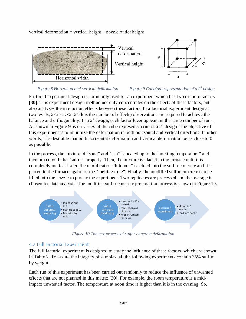
4.1 Fractional Factorial Experiment Design In this section both horizontal and vertical deformations are studied. When the molten sulfur concrete gets out of the nozzle outlet gravitational force deforms the extrudate which is still in hot paste form. As shown in Figure 8, the dotted line rectangle represents the dimension of nozzle outlet, which is 2.546” × 0.99”. The horizontal deformation and vertical deformation are defined as:
Figure 8 Horizontal and vertical deformation Figure 9 Cuboidal representation of a 23 design
Factorial experiment design is commonly used for an experiment which has two or more factors [30]. This experiment design method not only concentrates on the effects of these factors, but also analyzes the interaction effects between these factors. In a factorial experiment design at two levels, 2×2×…×2=2k (k is the number of effects) observations are required to achieve the balance and orthogonality. In a 2k design, each factor lever appears in the same number of runs. As shown in Figure 9, each vertex of the cube represents a run of a 23 design. The objective of this experiment is to minimize the deformation in both horizontal and vertical directions. In other words, it is desirable that both horizontal deformation and vertical deformation be as close to 0 as possible.
In the process, the mixture of “sand” and “ash” is heated up to the “melting temperature” and then mixed with the “sulfur” properly. Then, the mixture is placed in the furnace until it is completely melted. Later, the modification “bitumen” is added into the sulfur concrete and it is placed in the furnace again for the “melting time”. Finally, the modified sulfur concrete can be filled into the nozzle to pursue the experiment. Two replicates are processed and the average is chosen for data analysis. The modified sulfur concrete preparation process is shown in Figure 10.
Figure 10 The test process of sulfur concrete deformation
4.2 Full Factorial Experiment The full factorial experiment is designed to study the influence of these factors, which are shown in Table 2. To assure the integrity of samples, all the following experiments contain 35% sulfur by weight.
Each run of this experiment has been carried out randomly to reduce the influence of unwanted effects that are not planned in this matrix [30]. For example, the room temperature is a mid-impact unwanted factor. The temperature at noon time is higher than it is in the evening. So,
•Mix sand and ash
•Heat up to 160C•Mix with dry
sulfur
Sulfur concrete preparing
•Heat until sulfur melted
•Mix with liquid bitumen
•Keep in furnace for hours
Sulfur concrete
modifying
•Mix up to 1 minute
• Load into nozzle
Extrusion experiment
Horizontal width
Vertical height
Vertical deformation
2287
7
molten sulfur concrete solidifies faster and deforms less in the evening. The full factorial experiment design deformation data is obtained by measuring random points of the extrudate width and height using a caliper.
Table 2 Factors and levels, sulfur concrete extrudate experiment
Factors Level + -
A. Proportion of Ash 20% 10% B. Melting Temperature (C) 155 140
C. Melting Time (hours) 2 1
4.3 Experiment Analysis
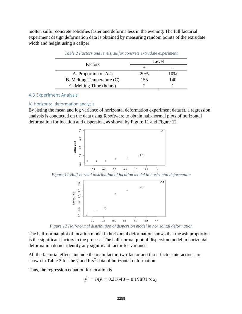
A) Horizontal deformation analysis By listing the mean and log variance of horizontal deformation experiment dataset, a regression analysis is conducted on the data using R software to obtain half-normal plots of horizontal deformation for location and dispersion, as shown by Figure 11 and Figure 12.
Figure 11 Half-normal distribution of location model in horizontal deformation
Figure 12 Half-normal distribution of dispersion model in horizontal deformation
The half-normal plot of location model in horizontal deformation shows that the ash proportion is the significant factors in the process. The half-normal plot of dispersion model in horizontal deformation do not identify any significant factor for variance.
All the factorial effects include the main factor, two-factor and three-factor interactions are shown in Table 3 for the y� and lns2 data of horizontal deformation.
Thus, the regression equation for location is
𝑦𝑦′� = 𝑙𝑙𝑙𝑙𝑦𝑦� = 0.31648 + 0.19881 × 𝑥𝑥𝐴𝐴
2288
8
Where y’=lny
Table 3 Factorial effects of horizontal deformation
Effect y� lns2 A 0.3976 0.5940 B -0.0726 -1.723 C 0.0336 -2.006
A:B -0.1041 -2.693 A:C 0.0340 2.208 B:C
A:B:C 0.0344 0.0602
0.0351 -0.3779
The interaction plot visualizes the influence of one factor depending on the level of another factor. Figure 13 is an interaction plot of melting temperature against ash proportion. The average of horizontal deformation is used as vertical axis. The solid and dotted lines show two levels of melting temperature (B factor), and the horizontal axis represents the influence of ash proportion (A factor). When melting temperature is at 140 ℃, the change of ash proportion causes more variance in horizontal deformation than that of 155℃. In Figure 14, when melting time is 1 hour, the change of ash proportion causes more variance in horizontal deformation than that of a 2-hour case.
Figure 13 Interaction plot of melting temperature against ash proportion
Figure 14 Interaction plot of melting temperature against ash proportion
B) Vertical deformation analysis Similar to the horizontal deformation analysis, a vertical deformation experiment dataset is listed by mean and log variance. During the width deformation process, the height of the extruded sample also slumps. A regression analysis is conducted on the data using R software, half-normal plots for location and dispersion and all factorial effects are obtained in Figure 15 and Figure 16.
2289
9
Figure 15 Half-normal distribution of location model in vertical deformation
Figure 16 Half-normal distribution of dispersion model in vertical deformation
The half-normal distribution of location model in vertical deformation does not identify any significant factor. The half-normal distribution of dispersion model in vertical deformation also does not identify any significant factor.
C) Deformation errors analysis In previous two deformation experiments on horizontal deformation and vertical deformation, only ash proportion is identified as a significant factor of horizontal deformation. The interaction effect of melting temperature against ash proportion and the interaction effect of melting time against ash proportion conduct very little influence on the deformation. Table 4 shows the statistical analysis of deformation on both directions.
Table 4 Horizontal and vertical data statistical analysis
For all eight groups, the horizontal deformation mean error of 4 groups is less than 5% and the vertical deformation mean error of 6 groups is less than 5%. Take the Group 5 for example, it has the horizontal deformation mean error of 4.73% and standard deviation of 0.022, and the vertical deformation mean error of 2.04% and standard deviation of 0.006. This deformation result meets the requirements.
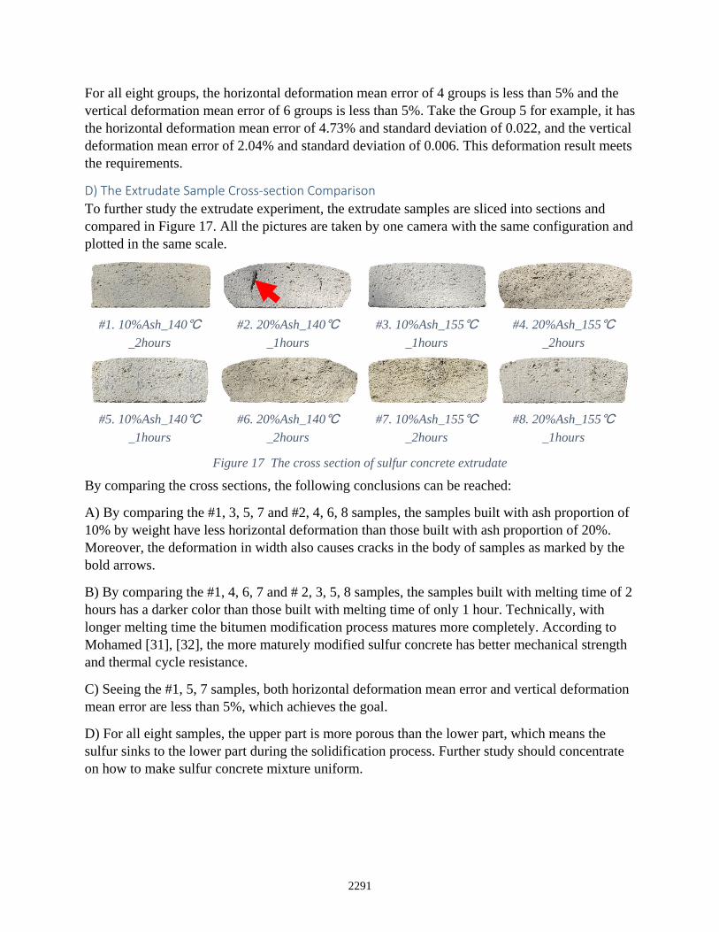
D) The Extrudate Sample Cross-section Comparison To further study the extrudate experiment, the extrudate samples are sliced into sections and compared in Figure 17. All the pictures are taken by one camera with the same configuration and plotted in the same scale.
#1. 10%Ash_140℃
_2hours #2. 20%Ash_140℃
_1hours #3. 10%Ash_155℃
_1hours #4. 20%Ash_155℃
_2hours
#5. 10%Ash_140℃
_1hours #6. 20%Ash_140℃
_2hours #7. 10%Ash_155℃
_2hours #8. 20%Ash_155℃
_1hours
Figure 17 The cross section of sulfur concrete extrudate
By comparing the cross sections, the following conclusions can be reached:
A) By comparing the #1, 3, 5, 7 and #2, 4, 6, 8 samples, the samples built with ash proportion of 10% by weight have less horizontal deformation than those built with ash proportion of 20%. Moreover, the deformation in width also causes cracks in the body of samples as marked by the bold arrows.
B) By comparing the #1, 4, 6, 7 and # 2, 3, 5, 8 samples, the samples built with melting time of 2 hours has a darker color than those built with melting time of only 1 hour. Technically, with longer melting time the bitumen modification process matures more completely. According to Mohamed [31], [32], the more maturely modified sulfur concrete has better mechanical strength and thermal cycle resistance.
C) Seeing the #1, 5, 7 samples, both horizontal deformation mean error and vertical deformation mean error are less than 5%, which achieves the goal.
D) For all eight samples, the upper part is more porous than the lower part, which means the sulfur sinks to the lower part during the solidification process. Further study should concentrate on how to make sulfur concrete mixture uniform.
2291
11
5. Conclusion
After numerous trial designs a small-scale auger extruder with vibrators is developed for regolith simulant sulfur concrete demonstration, a heated and low pressure extruder system has been especially developed for extrusion of molten sulfur concrete, and systematic experiments have been carried out to characterize and configure the material composition and preparation and the process parameters. The results indicate a consistent and robust process which has been confirmed through experiments.
A series of factorial experiments have been designed to study the influence of experimental parameters. By analyzing the results optimized factors have been achieved that can yield an extrudate deformation within 5% of total extrudate size as well as reduced leakage between the successive layers which result in smooth surfaces.
Acknowledgement
The research reported here has been supported by a NASA Innovative Advanced Concepts (NIAC) Grant No. NNX12AQ57G.
References
[1] B. Khoshnevis, M. Bodiford, K. Burks, E. Ethridge, D. Tucker, W. Kim, H. Toutanji, and M. Fiske, “Lunar contour crafting—a novel technique for ISRU-based habitat development,” Autom. Constr., vol. 13(1), no. January, pp. 5–19, 2004.
[2] B. Khoshnevis, “Automated construction by contour crafting - Related robotics and information technologies,” Autom. Constr., vol. 13, pp. 5–19, 2004.
[3] J. Zhang and B. Khoshnevis, “Optimal machine operation planning for construction by Contour Crafting,” Autom. Constr., vol. 29, pp. 50–67, 2013.
[4] B. Khoshnevis, S. Bukkapatnam, H. Kwon, and J. Saito, “Experimental investigation of contour crafting using ceramics materials,” Rapid Prototyp. J., vol. 7, no. 1, pp. 32–42, 2001.
[5] L. Angeles, “AUTOMATED CONSTRUCTION USING CONTOUR CRAFTING B. Khoshnevis, H. Kwon, and S. Bukkapatnam,” J. Manuf., pp. 497–504.
[6] B. Khoshnevis, D. Hwang, K.-T. Yao, and Z. Yah, “Mega-scale fabrication by contour crafting,” Int. J. Ind. Syst. Eng., vol. 1, no. 3, pp. 301–320, 2006.
[7] M. Khoshnevis, Behrokh; Carlson, Anders; Leach, Neil; Thangavelu, “Contour Crafting Simulation Plan for Lunar Settlement Infrastructure Buildup,” Earth Sp. 2012, pp. 1458–1467, 2012.
[8] H. Kwon, S. Bukkapatnam, B. Khoshnevis, and J. Saito, “Effects of orifice shape in
2292
12
contour crafting of ceramic materials,” Rapid Prototyp. J., vol. 8, no. 3, pp. 147–160, 2002.
[9] N. Leach, A. Carlson, B. Khoshnevis, and M. Thangavelu, “Robotic Construction by Contour Crafting: The Case of Lunar Construction,” Int. J. Archit. Comput., vol. 10, no. 03, pp. 423–438, 2012.
[10] N. J. Werkheiser, “On The Development of Additive Construction Technologies for Application to Development of Lunar / Martian Surface Structures Using In-situ Materials,” Sp. Conf. Expo., pp. 1–8, 2015.
[11] B. Khoshnevis, M. Thangavelu, X. Yuan, and J. Zhang, “Advances in Contour Crafting Technology for Extraterrestrial Settlement Infrastructure Buildup,” AIAA, vol. 5438, pp. 10–12, 2013.
[12] B. Khoshnevis, X. Yuan, B. Zahiri, Z. Jing, and B. Xia, “"Construction by contour crafting using sulfur concrete with planetary applications,” in Rapid Prototyping Journal, 2016, p. Vol. 22 Iss 5 pp.
[13] B. Khoshnevis, X. Yuan, B. Zahiri, and B. Xia, “Construction by Contour Crafting using Sulfur Concrete with Planetary Applications,” Solid Free Form Fabr. Symp., 2015.
[14] B. Khoshnevis and J. Zhang, “Selective Separation Sintering (SSS)-An Additive Manufacturing Approach for Fabrication of Ceramic and Metallic Parts with Applications in Planetary Construction,” in AIAA SPACE 2015 Conference and Exposition, 2015, p. 4450.
[15] H. Kwon, “Experimentation and Analysis of Contour Crafting (Cc) Process Using Uncured Ceramic Materials,” no. August, 2002.
[16] H. Kwon, S. Bukkapatnam, B. Khoshnevis, and J. Saito, “Effects of orifice shape in contour crafting of ceramic materials,” Rapid Prototyp. J., vol. 8, no. 3, pp. 147–160, 2002.
[17] B. Khoshnevis, R. Russell, H. Kwon, and S. Bukkapatnam, “Crafting large prototypes,” IEEE Robot. Autom. Mag., vol. 8, no. 3, pp. 33–42, 2001.
[18] D. Hwang and B. Khoshnevis, “CONCRETE WALL FABRICATION BY CONTOUR CRAFTING Dooil Hwang and Behrokh Khoshnevis,” 2004.
[19] D. Hwang and B. Khoshnevis, “An Innovative Construction Process-Contour Crafting,” 22nd Int. Symp. Autom. Robot. Constr. ISARC, no. Cc, 2005.
[20] K. Behdinan and B. Khoshnevis, “Methodology for design of a vibration operated valve for abrasive viscous fluids,” Mechatronics, vol. 23. pp. 1025–1036, 2013.
[21] K. Behdinan, “METHODOLOGY FOR DESIGN OF A VIBRATION OPERATED VALVE FOR ABRASIVE VISCOUS FLUIDS by,” Univ. South. Calif., vol. 53, no. 9, pp. 1689–1699, 2013.
[22] A. Gedik and A. H. Lav, “Determining Optimum Sulfur Content as Alternative Binder Additive in Asphaltic Concrete Pavements,” J. Mater. Civ. Eng., vol. 2, no. 7, pp. 1–12,
2293
13
2016.
[23] T. S. Lee, J. Lee, and K. Yong, “Acta Astronautica Manufacture of polymeric concrete on the Moon,” Acta Astronaut., vol. 114, pp. 60–64, 2015.
[24] B. Khoshnevis, X. YUAN, B. Zahiri, J. Zhang, and B. Xia, “Deformation Analysis of Sulfur Concrete Structures Made by Contour Crafting,” AIAA Sp. 2015 Conf. Expo., 2015.
[25] M. Rith, Y. Kyu, S. Woo, J. Young, and S. Hwan, “Analysis of in situ bond strength of bonded concrete overlay,” Constr. Build. Mater., vol. 111, pp. 111–118, 2016.
[26] S. Lim, “In-Situ Resource Utilisation ( ISRU ) derived extra-terrestrial construction processes using sintering-based additive manufacturing techniques – focusing on a lunar surface environment Conference Item,” J. Mater. Civ. Eng., 2015.
[27] R. P. Mueller, “Automated Additive Construction ( AAC ) for Earth and Space Using In-situ Resources,” Am. Soc. Civ. Eng., p. 2016, 2016.
[28] J. Moon, P. D. Kalb, L. Milian, and P. A. Northrup, “Characterization of a sustainable sulfur polymer concrete using activated fi llers,” Cem. Concr. Compos., vol. 67, pp. 20–29, 2016.
[29] L. Wan, R. Wendner, and G. Cusatis, “A novel material for in situ construction on Mars : experiments and numerical simulations,” Constr. Build. Mater., vol. 120, pp. 222–231, 2016.
[30] C. F. J. WU, No TitleExperiments: Planning, Analysis, and Optimization (Second Edition). Wiley Online Library, 2009.
[31] A.-M. O. Mohamed and M. El Gamal, “Sulfur based hazardous waste solidification,” Environ. Geol., vol. 53, no. 1, pp. 159–175, 2007.
[32] A.-M. O. Mohamed and M. El-Gamal, Sulfur concrete for the construction industry: a sustainable development approach. J. Ross Publishing, 2010.