DOE/OR/01-2739&D21 Phase 1 Field Sampling Plan for the Proposed Environmental Management Disposal Facility for Comprehensive Environmental Response, Compensation, and Liability Act Oak Ridge Reservation Waste Disposal, Oak Ridge, Tennessee Comment [PAL(1]: UPDATE FOR D2
Transcript
DOE/OR/01-2739&D21
Phase 1 Field Sampling Plan for the Proposed Environmental Management Disposal Facility for Comprehensive
Environmental Response, Compensation, and Liability Act Oak Ridge Reservation Waste Disposal,
Oak Ridge, Tennessee
Comment [PAL(1]: UPDATE FOR D2
DOE/OR/01-2739&D21
Phase 1 Field Sampling Plan for the Proposed Environmental Management Disposal Facility for Comprehensive
Environmental Response, Compensation, and Liability Act Oak Ridge Reservation Waste Disposal,
Oak Ridge, Tennessee
Date Issued—August December 2017
Prepared for the U.S. Department of Energy
Office of Environmental Management
URS | CH2M Oak Ridge LLC Safely Delivering the Department of Energy’s Vision
for the East Tennessee Technology Park Mission under contract DE-SC-0004645
This page intentionally left blank.
iii
CONTENTS
FIGURES ...................................................................................................................................................... v
TABLES ....................................................................................................................................................... v
ACRONYMS .............................................................................................................................................. vii
6. SAMPLING REQUIREMENTS AND DOCUMENTATION ............................................................ 35 6.1 GROUNDWATER EVALUATION ........................................................................................... 35 6.2 SURFACE WATER EVALUATION ......................................................................................... 40
6.2.1 Field Identification of Surface Water Features ............................................................ 40 6.2.2 Surface Water Flow Measurements ............................................................................. 40
APPENDIX A. QUALITY ASSURANCE PROJECT PLAN FOR THE PROPOSED EMDF DESIGN INVESTIGATION, OAK RIDGE, TENNESSEE .................................................... A-1
APPENDIX B. MEASUREMENT AND TESTING APPROACH AND METHODS ........................... B-1
Comment [PJ(2]: Will be fixed in final version.
iv
This page intentionally left blank.
v
FIGURES
Fig. 1. ORR—proposed EMDF CBCV site location. ................................................................................... 2 Fig. 2. CBCV site topographic setting. ......................................................................................................... 6 Fig. 3. General geology of the Bear Creek Valley. ....................................................................................... 7 Fig. 4. Generalized cross-section of the CBCV site...................................................................................... 9 Fig. 5. Projected pre-construction groundwater elevations beneath the EMDF waste cells. ...................... 10 Fig. 6. Surface water capture basins in Central Bear Creek Valley. ........................................................... 11 Fig. 7. Bedrock observed in the Nolichucky Shale outcrop area of the NT-11 stream channel. ................ 12 Fig. 8. Nolichucky Shale outcrop in NT-11 stream channel. ..................................................................... 12 Fig. 9. Large macropore channel in soil. ..................................................................................................... 13 Fig. 10. Overland flow inlet to soil channel. ............................................................................................... 13 Fig. 11. Headwater soil channel daylighting point. .................................................................................... 14 Fig. 12. Generalized flow paths for shallow/intermediate groundwater toward Bear Creek. .................... 15 Fig. 13. Project organization. ...................................................................................................................... 17 Fig. 14. Approximate Phase 1 measurement and testing locations for CBCV site. .................................... 22
TABLES
Table 1. DQO summary for groundwater data acquisition ......................................................................... 19 Table 2. DQO summary for surface water flow data acquisition ............................................................... 23 Table 3. DQO summary for seismic data acquisition ................................................................................. 25 Table 4. DQO summary for geotechnical data acquisition ......................................................................... 28 Table 5. Summary of subsurface sample collection locations .................................................................... 37 Table 6. Groundwater-level, location-specific target depths and tests ....................................................... 38
vi
This page intentionally left blank.
vii
ACRONYMS
BCV Bear Creek Valley CBCV Central Bear Creek Valley CERCLA Comprehensive Environmental Response, Compensation, and Liability Act of 1980 cfs cubic feet per second D Drainage DOE U.S. Department of Energy DQO data quality objective E East EMDF Environmental Management Disposal Facility EPA U.S. Environmental Protection Agency FLUTe Flexible Liner Underground Technologies, LLC FFA Federal Facility Agreement NT North Tributary OREIS Oak Ridge Environmental Information System OREM Oak Ridge Office of Environmental Management ORNL Oak Ridge National Laboratory ORR Oak Ridge Reservation QA quality assurance QAPP Quality Assurance Project Plan QC quality control RI/FS Remedial Investigation/Feasibility Study ROD Record of Decision SME subject matter expert TDEC Tennessee Department of Environment and Conservation UCOR URS | CH2M Oak Ridge LLC UPF Uranium Processing Facility USGS U.S. Geological Survey W West
Comment [PJ(3]: Will be updated in final version.
viii
This page intentionally left blank.
1
1. INTRODUCTION
The mission of the U.S. Department of Energy (DOE) Oak Ridge Office of Environmental Management (OREM) is to decommission and demolish numerous facilities and conduct remedial actions under the Comprehensive Environmental Response, Compensation, and Liability Act of 1980 (CERCLA) on the Oak Ridge Reservation (ORR) in Oak Ridge, Tennessee, and associated sites. This effort requires an estimated 2.2 million cubic yards of landfill disposal capacity beyond what is available in the existing Environmental Management Waste Management Facility for the disposal of wastes from CERCLA cleanup actions. The Remedial Investigation/Feasibility Study for the Comprehensive Environmental Response, Compensation, and Liability Act Oak Ridge Reservation Waste Disposal, Oak Ridge, Tennessee (RI/FS) (DOE 2017) evaluated several alternatives for the disposal of this waste, including no action, off-site disposal, and onsite disposal.
An approximately 70-acre tract in the Central Bear Creek Valley (CBCV) site appears to be the best site in terms of available capacity and location. This site is used as the basis for the planned characterization efforts.
This Field Sampling Plan describes the objectives, requirements, and approach to collecting groundwater elevations and surface water flow data, and conducting geotechnical testing and exploration, and performing geophysical (seismic) studies needed to support to characterize Site 7c, the current DOE-preferred location for the design of the proposed Environmental Management Disposal Facility (EMDF) (Fig. 1) on the DOE ORR. This Field Sampling Plan identifies the initial site characterization activities (Phase 1) that have been agreed to by the FFA parties to be included in the Administrative Record prior to the public comment period on the preferred EMDF alternative. Additional investigations will be conducted in the future to obtain geotechnical and geophysical data for the EMDF design, including support facilities, and required relocation of the Haul Road and Bear Creek Road. In addition, baseline sampling to determine the baseline analytical data will be performed as part of a future investigation phase. Longer-term monitoring of groundwater and surface water monitoring locations identified in this Field Sampling Plan and Tthese future design investigations are not within the scope of this Field Sampling Plan.
The data collection described in this Field Sampling Plan also will contribute to understanding the hydrogeologic setting for the CBCV site during the planning process and preferred alternative selection. These data will be used to better understand and validate the underlying groundwater assumption for this site to support the Federal Facility Agreement for the Oak Ridge Reservation (DOE 1992) (FFA) parties (U.S. Environmental Protection Agency [EPA], Tennessee Department of Environment and Conservation [TDEC], and DOE) in selecting and codifying a decision in a Record of Decision (ROD).
This plan uses the results of the data quality objective (DQO) process as specified in Guidance on Systematic Planning Using the Data Quality Objectives Process - EPA QA/G-4 (EPA 2006). The DQO process focused on the use of the data for engineering design. The FFA parties agreed that subsets of this data could be used to validate underlying assumptions used for selecting the remedy.
The project-specific Quality Assurance Project Plan (QAPP) for the Proposed EMDF Design Investigation (Appendix A) identifies the procedures that will be followed in the collection, custody, sample handling, data management, and quality control (QC) activities for all anticipated EMDF investigation activities, including future design investigation activities not described in this document.
Safety concerns associated with the sampling will be addressed in contractor-prepared, task-specific work packages that will be approved by the appropriate disciplines. These work packages and contract documents will contain the detailed work scope for implementing this work.
2
Fig. 1. ORR—proposed EMDF CBCV site location.
3
This plan intends to deliver usable data within current constraints posed by physical site conditions and contractual obligations. The overall objective of this plan is to provide the strategy to collect sufficient representative data to address the DQOs. The specific scope of this plan is to obtain the following data:
• Groundwater elevation data
• Surface water flow data
• Geotechnical and geophysical data for landfill stability
4
This page intentionally left blank.
5
2. HYDROGEOLOGIC SETTING
2.1 GENERAL SITE CONDITIONS
The CBCV site is situated within an upland area located between north-south trending valleys of North Tributary (NT)-10 and NT-11. Drainages within the site are Drainage (D)-10 West (W), parallel to and just west of NT-10, and D-11 East (E), an east-west trending feature that drains westward into NT-11 near the center of the site (Fig. 2).
An additional shallow east-west trending drainage was present in the southern part of the area prior to construction of the Uranium Processing Facility (UPF) wet spoils pile. This drainage was noted as dry when previously observed. The drainage is now covered by the UPF wet spoils pile; however, there is a downgradient seep within this drainage area.
The CBCV site and surrounding area are forested, except for areas along the south side between the Haul Road and Bear Creek Road, where the area has been cleared. The cleared area includes a recent soil staging area along the southern margin and two wetland basins completed in 2015 for the Y-12 National Security Complex compensatory wetland mitigation. The Haul Road and Bear Creek Road are located at the southern edge of the site and will need to be relocated prior to EMDF construction.
The Bear Creek Valley (BCV) has been extensively investigated. Geologic, hydrogeologic, and groundwater contamination conditions have been characterized extensively and there is routine monitoring of surface water conditions. There also have been additional investigations conducted for BCV to identify wetlands, ecological species of concern, and cultural resources. However, no CBCV site-specific investigations have been conducted.
The available hydrogeologic data for various potential EMDF sites in BCV are described in Appendix E and Sects. 2 and 5 of the RI/FS (DOE 2017). The information available for BCV was used to summarize various potential CBCV site conditions discussed below.
2.2 GEOLOGY/HYDROGEOLOGY
The general subsurface hydrogeological conditions at the CBCV site are known from previous characterization performed of the BCV watershed (DOE 2014). The general hydrogeological setting is provided in Fig. 3.
The waste footprint at the CBCV site predominantly overlies bedrock of the Conasauga Group (Fig. 3), including the Rogersville Shale, Dismal Gap/Maryville Formation, and Nolichucky Shale. Recent alluvium is present on the valley floor along D-10W (eastern side of the site).
These formations are dominantly shales, siltstones, and mudstones. There is little limestone present in the bedrock underlying the proposed disposal cells, even in the Maryville Formation. The crest of the knoll below the north center of the footprint is underlain by the erosion-resistant Dismal Gap/Maryville Formation. The typical weathering profile of topsoil, silty/clayey soil residuum, saprolite, and fractured bedrock are expected across the undisturbed site areas.
6
Fig. 2. CBCV site topographic setting.
7
Fig. 3. General geology of the Bear Creek Valley.
8
In BCV, the average dip of the formations is 45° southeast (Fig. 4). Some microfolds to mesofolds are present. Fractures are present within the bedrock and control the location of the NTs. These fractures and macro/micropores within the remaining soils/saprolite and bedrock provide the primary routes for groundwater flow (and contaminant transport) below and downgradient of the CBCV site footprint (DOE 2016).
Thin layers of alluvial and colluvial soils may be present along streams, drainage ways, and the base of steeper slopes. These soils may be looser, more compressible, and more permeable than the underlying residual soils or saprolite. As noted in Geology of the West Bear Creek Site (Oak Ridge National Laboratory [ORNL] 1989):
“The soils are underlain by a comparatively thick saprolite zone which varies from 10 to 20 ft thick. The saprolite is composed of weathered bedrock which has lost its rock cement but retained its bedding features. Its upper portions can be readily penetrated with a hand auger. The saprolite/bedrock contact is gradational due to decreasing weathering with depth but is typically defined as the depth of machine auger refusal.”
2.2.1 Groundwater Elevation
There are no current groundwater elevation data available for the CBCV site. Available groundwater elevation data were projected to this site from adjacent areas with similar hydrogeologic conditions. The current projected groundwater elevations and relation to the geologic buffer and projected bottom of waste are shown in Fig. 5. However, as the landfill is constructed, the surface water and groundwater flow regime will be modified.
Construction of the landfill may initially result in elevated groundwater elevations if heavy precipitation is encountered following vegetation and topsoil removal. However, the completion of landfill construction will reduce the area available for groundwater recharge from precipitation. Topsoil materials will be removed and replaced with engineered fill and geologic buffer clays that will reduce infiltration. While groundwater within undisturbed in situ natural materials will continue to migrate downgradient, the elimination of significant portions of the former natural recharge area will greatly reduce the overall groundwater flux. As a result, the groundwater elevation will be reduced and will be maintained lower than the geologic buffer, including reduction to the elevation of the groundwater mound below the central knob/spur ridge (DOE 2017, Appendix E).
2.2.2 Potential for Karst Features
Karst features such as sinkholes, sinking streams, and resurgent springs have not been documented within the formations underlying the proposed footprint of the CBCV site. Karst features are documented within the Maynardville outcrop belt south of the CBCV site. Contact between the Nolichucky Shale and Maynardville Limestone is located approximately 300 ft from the proposed southernmost waste limit (DOE 2017).
2.3 SURFACE WATER HYDROLOGY
The CBCV site surface water systems are fed by precipitation, surface runoff and shallow stormflow, and both shallow and deeper groundwater that discharges via springs and seeps. In areas underlain by Conasauga Group shales, as much as 90 percent of the water entering the groundwater system flows rapidly through highly porous, shallow soil. In areas underlain by soluble, massive carbonate bedrock of the Maynardville Limestone, a larger fraction of the water enters the groundwater system by conduit flow through deeper flow pathways (DOE 2016).
9
Fig. 4. Generalized cross-section of the CBCV site.
Continuous flow monitoring data are not available for NT-10, NT-11 or D-10W. The available USGS base flow data indicate that base flow is continuous along the D-10W and NT-11 stream channels during the winter/spring non-growing wet season. During the summer/fall growing season with warm and often dry conditions, base flow is negligible and limited to pulsed flow associated with significant storm rainfall events. Flow monitoring for Bear Creek downstream of CBCV site indicates continuous flow in Bear Creek (DOE 2017).
Wet season base flows are relatively low along D-10W and vary from 0.01 cubic feet per second (cfs) (4.5 gpm) at a headwater location to a maximum rate 0.04 cfs (18 gpm) southeast of the site. Wet season
11
base flows along NT-11 are slightly higher ranging from 0.01 cfs (4.5 gpm) at a headwater spring location to 0.14-0.16 cfs (63-72 gpm) southwest and downstream of CBCV site (DOE 2017).
2.3.2 CBCV Site Initial Preliminary Investigation
A limited site walkover of surface water conditions at the CBCV site was conducted on July 7, 2016, by a subject matter expert (SME) from the URS | CH2M Oak Ridge LLC (UCOR) Water Resources Restoration group to observe stream channels and other relevant features of NT-10, D-10W, and NT-11. The site visit occurred approximately 2-3 hours after a thundershower and following approximately 0.8 in. of rain the previous day.
The areas of the three surface water basins between the crest of Pine Ridge on the northwest and the geologic contact between the Maynardville Limestone and the Nolichucky Shale on the southeast are shown in Fig. 6. The Maynardville/Nolichucky geologic contact is recommended as the most downstream flow measurement location because further downstream surface water tends to sink into the Maynardville karst, causing a low bias to the flow data.
Fig. 6. Surface water capture basins in Central Bear Creek Valley.
12
The NT-11 stream channel in the Nolichucky Shale outcrop area typically has a discontinuous outcrop of somewhat weathered bedrock (Figs. 7 and 8).
Fig. 7. Bedrock observed in the Nolichucky Shale outcrop area of the NT-11 stream channel.
Fig. 8. Nolichucky Shale outcrop in NT-11 stream channel.
The walkover included NT-11 from approximately the “dog-leg” bend in the Nolichucky Shale to its head of flow in the Rogersville Shale. Next, the walkover route crossed the saddle to D-10W and proceeded southeast to approximately the Haul Road, across the weak ridge in the Maryville Limestone, and into the lower NT-10 basin above the Haul Road. Surface water features in these areas were difficult to see due to the heavy vegetation that covers much of the area to the southeast and along the Haul Road.
The CBCV site area slopes to the south-southeast. As described in the Oak Ridge Reservation Physical Characteristics and Natural Resources (ORNL 2006), sloping land surfaces on the ORR exhibit the characteristics of hillslope hydrology. In undisturbed, naturally vegetated areas such as the CBCV site, an estimated 80 to 90 percent of precipitation is captured and discharged from the 3- to 6.5-ft (1- to 2-m) storm-flow zone/root zone and does not infiltrate into the groundwater table. During November through March when plants are not consuming water and shallow soils are saturated, lateral drainage of water
Bedrock Bedrock
13
occurs on slopes through macropores (e.g., holes left by the decay of dead plant roots and animal burrows) as well as through vertical seepage to the water table through pervious zones (Clapp 1997).
Several noteworthy soil macropore and channel features were observed in the upper 3 ft of soil in the Nolichucky Shale. A shallow macropore/soil channel that transmits percolation water from soils on the east to the NT-11 stream channel in the Nolichucky Shale outcrop area is shown in Fig. 9. Overland surface water flow into a soil macropore/channel is shown in Fig. 10. The location where that subsurface channel is daylighted a short distance downstream due to collapse and downstream transport of shallow soils is shown in Fig. 11. There was a small amount of water flow emanating from the channel as shown in Fig. 11. This feature joined another branch of subsurface flow from an unnamed western valley. These types of soil drainage features are common in undisturbed ORR soils and are a part of the stormflow system that rapidly conducts percolation water laterally downslope to stream channels.
The east-west valley draining to NT-11 (Figs. 2 and 6), also referred to as D-11E, located on the western slope of the high knob in the Maryville Limestone, was inspected for evidence of surface water features. It was apparent that overland flow occurs in the valley, however, no defined surface water channel was observed.
A well-established surface channel approximately 1-ft wide by 1-ft deep was encountered in the D-10W valley. The channel contained isolated pools of standing water, but no flow was occurring. The D-10W valley is approximately 50 percent less incised than the adjacent NT-10 and NT-11 valleys and has a much narrower headwater basin.
2.4 SITE CONCEPTUAL MODEL
Key general elements of the site conceptual model for the EMDF CBCV site are shown in Fig. 12.
The majority of flow from upland areas is directed towards the valley axis by the north tributaries. Groundwater in bedrock that does not discharge directly to surface water (e.g., within a confined system) has an upward gradient because of the pressure gradient of recharge from Pine Ridge and discharges into the Bear Creek–Maynardville Limestone drainage system.
Bear Creek flows more or less continuously over non-karst bedrock, but loses flow to subsurface conduits where it crosses karst features in the Maynardville Limestone. Underflow conduits in the Maynardville Limestone continuously convey base flow, while overflow conduits and Bear Creek carry high flows during the wet season and heavy rainfall events.
15
Fig. 12. Generalized flow paths for shallow/intermediate
groundwater toward Bear Creek.
16
This page intentionally left blank.
17
3. PROJECT ORGANIZATION
The organizational structure for this project is presented in Fig. 13.
Fig. 13. Project organization.
OREM or their designees are responsible for ensuring that the field activities are performed as described in this plan. OREM expects to fulfill these responsibilities through UCOR or other contractor staff, with additional review, oversight, and guidance provided by OREM personnel to ensure these activities are performed safely and compliantly. Additional information on the project organization is provided in the QAPP (Appendix A, Sect. A.2).
18
This page intentionally left blank.
19
4. DATA QUALITY OBJECTIVES
This plan builds upon previous activities and, through the use of the DQO process (EPA 2006), identifies data needs that become the focus for this investigation. The DQOs are summarized in Tables 1 through 4.
Table 1. DQO summary for groundwater data acquisition DQO step Groundwater data for design
State the Problem
The CBCV site is being proposed for disposal of soils and demolition debris that may contain mixed metals, PCBs, and radioactive constituents (Fig. 1). Additional contaminants (e.g., volatile organic compounds) could also be present in materials disposed in the EMDF. If the proposed lined waste disposal facility fails, then those constituents could migrate to groundwater and eventually to surface water in Bear Creek, where they may pose a risk to human or ecological receptors.
Identify the Decision (the Design Criteria)
Design criteria for hydrogeologic (groundwater) conditions at the CBCV site include maintaining groundwater elevations beneath a geologic buffer at least 10 ft below the liner system. The FS assumes that the predicted pre-construction groundwater table may be higher than this design criterion. The principal study questions include (1) Where is the natural seasonal high groundwater table and where does it currently encroach into the design elevations? (2) Where groundwater is higher than the design criteria, will design adjustments will be required (e.g., increased elevation of the liner system)? (3) Are subsurface pathways present with relatively higher hydraulic conductivities? (4) Where is the Maynardville contact and does it underlie a buffer zone surrounding the landfill? and (4) Where surface water diversions or French drains are used, what is the predicted groundwater flow to be captured and how does the permeability of unconsolidated material above bedrock affect that flow? Note: The FS design assumes that groundwater is uncontaminated and may be discharged directly to surface water without treatment.
Identify Inputs to the Decision (to the Design Calculations)
For determining where the seasonal high groundwater table may encroach into the design elevations, the following design information is needed: • Seasonal high groundwater table (potentiometric surface, piezometric levels, or static groundwater
pressures) across the site • Adjustment for post-construction conditions For determining the location of the Maynardville Formation sufficiently for the design:
• Bedrock stratigraphy at the surface and beneath the site For determining the predicted groundwater elevation and flow to surface water diversions or French drains sufficient for the design purposes, the following is needed: • Hydraulic conductivity, soil stratigraphy, and hydraulic gradients/groundwater flow rates (both
horizontal and vertical) in the regolith and bedrock beneath the site
Define the Study Boundaries
The spatial boundaries of the study are hydraulic divides (e.g., Pine Ridge upgradient of EMDF to the north, NT-10 stream to the east, NT-11 to the west, and Bear Creek to the south). The vertical subsurface boundary extends into the uppermost bedrock below the proposed liner to assess vertical gradients. The temporal boundaries of the study are seasonal hydrologic changes that would affect the groundwater table and groundwater flow, including (1) typical wet precipitation season/anticipated high groundwater season (December-April) and (2) typical dry season (August-October). Piezometers installed in similar conditions at EMWMF, along with associated precipitation data, will be used for long-term monitoring of precipitation and groundwater elevations. Similarly located piezometers at EMWMF will be used to provide input and insight into the conditions at the CBCV site.
Develop a Decision Rule
Design criteria include maintaining a geologic buffer of 10 ft above seasonal high groundwater. The geologic buffer must have a maximum saturated hydraulic conductivity of 10-5 cm/sec. In situ materials may be used as part of the 10-ft-thick geologic buffer layer if these are demonstrated to satisfy the conductivity requirement.
Formatted: Font: 9.5 pt
Formatted: Font: 9.5 pt
Formatted: Font: 9.5 pt
Formatted: Font: 9.5 pt
Formatted: Font: 9.5 pt
20
Table 1. DQO summary for groundwater data acquisition (cont.)
DQO step Groundwater data for design Develop a Decision Rule (cont.)
If the predicted post-construction groundwater table is above the geologic buffer, then the design elevation must be increased or a French drain or other groundwater control system must be included in the design. If the predicted post-construction groundwater elevations and flows using the planned French drains are insufficient to lower the groundwater table to this allowable level, then the design must be revised to maintain the geologic buffer layer. If the measured hydraulic conductivity is higher than this allowable level (10-5 cm/sec), then the design must be modified by raising the liner grades to provide a compensatory thicker geologic buffer for hydraulic conductivity equivalency, increasing the thickness of the clay liner, or other means.
Data collection and analyses shall be as established using the ASTM procedures and guidance and UCOR procedures provided in Appendix B, Sect. B.3. The current version of these documents will be used. • Laboratory samples will provide additional information to correlate with field measurements
and recompacted bulk soil samples can be used to replicate as-placed values. Because of the small sample size, these samples may underestimate the permeability of the in situ materials. These sample results will be used in conjunction with the slug tests and FLUTe tests to develop a more complete picture of the hydraulic conductivity present in situ. Potentiometric levels need to be determined to at least 0.1 ft accuracy (objective is 0.05 ft).
• FLUTe transmissivity profiling will be used to measure the flow paths from bedrock boreholes that will be developed as piezometers. About 1 percent of the transmissivity remaining below the descending liner at any depth in the hole is the limit of resolution. For that reason, the resolution in the bottom portion of the hole is better than in the upper portion of the hole.
Hydraulic conductivities need to be determined within one order of magnitude since the natural variations within the formations are likely high. Spatial variations are not expected to greatly affect design results because of the known low hydraulic conductivities within the residuum. At least 13 7 locations spatially covering the cell footprint will be appropriate. However, if the measured hydraulic conductivity is variable across the CBCV site, or if there are uncertainties in the hydraulic conductivity due to small sample size, additional protective measures (e.g., a thin layer of low permeability material) may be considered as part of the design in addition to native materials.
Optimize the Design
The regolith (soils/saprolite) stratigraphy will be characterized within the EMDF design area: • Complete 17 8 boreholes within the EMDF footprint (Fig. 14) to characterize regolith
lithology, thickness, and uppermost bedrock interfaces by collecting and logging core samples. Boreholes will extend from the surface to approximately at least 10 ft below the top of bedrock. Test borings will be conducted in accordance with UCOR procedures or equivalent.
• Characterize temporal variation in water levels in the shallow and intermediate soils/saprolite currently at the projected elevation of the geologic buffer zone. Locations of existing and new water-level measurement locations are shown in Fig. 14. Piezometers will be screened and sand packed.
• Install three well points along drainages to monitor the groundwater/surface water interface (Fig. 14).
• Perform laboratory hydraulic conductivity tests on representative undisturbed soil samples. Soil samples subjected to laboratory hydraulic conductivity testing also will be tested to determine grain size, Atterberg limits (liquid limit, plastic limit, and plasticity index), USCS,
Comment [PJ(4]: Tables will be reformatted in final version.
21
and specific gravity.
22
Fig. 14. Approximate Phase 1 measurement and testing locations for CBCV site.
23
Table 1. DQO summary for groundwater data acquisition (cont.)
DQO step Groundwater data for design • FLUTe testing will be performed in accordance with the vendor’s specifications and operating
procedures for bedrock piezometers to evaluate hydraulic conductivity and detect zones of relatively higher conductivity (if present).
• Piezometer installations will be completed in accordance with UCOR procedures or equivalent.
• Water-level measurements will be obtained in accordance with UCOR procedures or equivalent.
ASTM = American Society for Testing and Materials CBCV = Central Bear Creek Valley DQO = data quality objective EMDF = Environmental Management Disposal Facility EMWMF = Environmental Management Waste Management Facility FLUTe = Flexible Liner Underground Technologies, LLC
FS = Feasibility Study NT = North tributary PCB = polychlorinated biphenyl UCOR = URS | CH2M Oak Ridge LLC USCS = Unified Soil Classification System
Table 2. DQO summary for surface water flow data acquisition
DQO step Surface water data for design State the Problem
The CBCV site is being considered for disposal of soils and demolition debris that may contain mixed metals, PCBs, and radioactive constituents (Fig. 1). Additional contaminants (e.g., volatile organic compounds) could also be present in materials disposed in the EMDF. The proposed footprint is located in an area of several surface water features, including two streams (NT-10 and NT-11) and other natural drainages. The landfill design must address these surface water features adequately to prevent potential impacts to the landfill liner and structure and to prevent a pathway for potential leakage migration and potential risk to human or ecological receptors.
Identify the Decision (the Design Criteria)
Design criteria for surface water conditions at the CBCV site include controlling the stormwater/surface water flow around the facility. The principal study questions include the following: • Does surface water in NT-10, D-10W, D-11E, and NT-11 (Fig. 14) result from
precipitation/overland flow, groundwater, or both? This information will be used to determine the appropriate approach for surface water controls.
• Are sections of these streams gaining and losing stretches? This information will be used to design appropriate surface water controls. What are the surface water runoff/flow volumes at NT-10, D-10W and NT-11? The calculated runoff (using the estimated runoff coefficient) will be used in conjunction with the groundwater measurements to address the surface water design criteria. D-11E drainage will be covered by the landfill and does not require a flow evaluation.
Identify Inputs to the Decision (to the Design Calculations)
The following design information is needed to determine the design for surface water controls: • Surface water capture basin areas, surface water budgets, and potential runoff volumes for
NT-10, D-10W, and NT-11 • Location of groundwater seeps, springs, or other sources of groundwater contribution in the
channels • Current and predicted groundwater elevations • Site topography and features • Analysis and characterization of the current stream channel morphology to provide guidance
as to the dimension, pattern, and profile of any planned diversions for long-term stability • Local climate information
24
Table 2. DQO summary for surface water flow data acquisition (cont.)
DQO step Surface water data for design Define the Study Boundaries
The spatial boundaries of the study are the surface water capture basins as shown in Fig. 6.
Develop a Decision Rule
If localized storm/precipitation events result in storm flows with the streams/drainages of NT-11, NT-10, and/or D-10W, then the design must consider such storm flows in sizing of diversion or surface water conveyances. If shallow groundwater flow results in gaining conditions in the streams/drainages near the perimeter embankments, then the design must consider the vertical and lateral influences of shallow groundwater flow on diversion or surface water conveyances. The proposed data gathered from the site (primarily in the form of surface vegetation, surface soil conditions, site features, and stream measurements) will be used to support an estimate of the runoff coefficient to use in stormwater generation modeling. No specific measurements are proposed to calculate that coefficient. The calculated runoff (using the estimated runoff coefficient) will be used in conjunction with groundwater measurements to address the surface water design criteria.
Develop a Decision Rule (cont.)
If deeper groundwater flow results in encroachment into the geologic buffer, then the design must consider the influences of such deeper groundwater flow on the surface water diversion.
Data collection and analyses shall be as established using the UCOR procedures provided in Appendix B, Sect. B.4. The current versions of these procedures will be used.
Optimize the Design
Place surface water flow measurement stations in the Nolichucky Shale outcrop areas in the lower reaches of NT-10 and NT-11. A second surface water flow measurement station will be placed along NT-11 south of the Haul Road (Fig. 14). Locations will be selected following a site walkover. Place two surface water flow measurement stations in D-10W: (1) upstream of the Haul Road in an area where surface water flow diversion is considered, and (2) downstream of Bear Creek Road near the projected Nolichucky Shale/Maynardville Limestone geologic contact (Fig. 14). Perform a detailed site walkover during the wet season (December-April) to identify seeps, springs, and other expressions of shallow groundwater in NT-10, D-10W, and NT-11. The walkover will include a description every 50 ft (as access allows and is appropriate) and field measurements of temperature, specific conductivity, and pH.
CBCV = Central Bear Creek Valley D = drainage DQO = data quality objective E = east
NT = North Tributary PCB = polychlorinated biphenyl UCOR = URS | CH2M Oak Ridge LLC W = west
25
Table 3. DQO summary for seismic data acquisition
DQO step Seismic characteristics State the Problem
The CBCV site is being proposed for disposal of soils and demolition debris that may contain mixed metals, PCBs, and radioactive constituents (Fig. 1). If the proposed lined waste disposal facility fails due to seismic forces during an earthquake, then those constituents could migrate to groundwater and eventually to surface water in Bear Creek, where they may pose a risk to human or ecological receptors.
Identify the Decision (the Design Criteria)
Design criteria for an engineered landfill at the CBCV site include maintaining stability and limiting deformation of the landfill in the event of an earthquake to prevent loss of containment. The landfill could become unstable or deform excessively either by direct shaking during an earthquake, by liquefaction, or by cyclic degradation of the foundation soils. The principal study questions include (1) What is the earthquake shaking on bedrock at the site? (2) What is the site response of the soil on top of the bedrock? (3) Will the subsurface conditions support the engineered landfill during a seismic event without failure or excessive deformation? (4) Are the subsurface materials susceptible to liquefaction or cyclic degradation? (5) Will the subsurface conditions support the engineered landfill without excessive deformation following a seismic event, including any potential liquefaction or cyclic degradation, or is ground improvement required? and (6) Will there be slope instability during the seismic shaking? To better model earthquake ground motions, a site-specific, seismic site response analysis will be performed. Dynamic site characterization data needed to perform a site-specific, seismic site response analysis includes the following: • Subsurface soil and bedrock profile or stratigraphy • Groundwater levels • Unit weights of soil and rock layers • Shear and compression wave velocity profiles with depth • Depth to bedrock layer(s) from which earthquake ground motion is being propagated • Variation of shear modulus with strain (or modulus reduction curve) • Variation of damping with strain (or damping ratio curve) For performing seismic stability and deformation analyses and other seismic-related analyses (e.g., earthquake-induced settlement or lateral spreading), the following geotechnical and geophysical parameters are needed: • Soil and bedrock stratigraphy • Soil classification and index properties (e.g., grain size, Atterberg limits, specific gravity) • Groundwater levels • Relative density of cohesionless soils • Over consolidation ratio of cohesive soils • Unit weights and dynamic shear strengths of bedrock and residuum/soil; dynamic shear
strengths are often estimated from static drained and undrained shear strengths • Residual (or post-earthquake) static shear strengths of bedrock and soil/residuum • Compressibility parameters of bedrock and soil/residuum • Orientation and characteristics of rock discontinuities • Shear wave velocity or initial (small strain) shear modulus • Compression wave velocity • Poisson’s ratio of the bedrock and soil/residuum • Cyclic stress-strain behavior, including modulus reduction curve and damping ratio curve
26
Table 3. DQO summary for seismic data acquisition (cont.)
DQO step Seismic characteristics Identify the Decision (the Design Criteria) (cont.)
For determining the liquefaction resistance, cyclic resistance, and cyclic degradation of soils, the following geotechnical parameters are needed: • Field blow counts (SPT N-values), percent fines, Atterberg Limits, moisture contents, SPT
hammer input energy, SPT and drilling methodology, groundwater levels, unit weights of soil strata, shape of undrained monotonic (non-cyclic) stress-strain curves and peak undrained strengths of clay-like materials, and ratio of compressional to shear wave velocities (P-wave/ S-wave). (Note cone penetrometer tests are not proposed to evaluate liquefaction potential and other dynamic soil behavior at this site because the typical soil profile is very thin and is comprised of stiff to very hard, non-sensitive, clayey soils.)
Define the Study Boundaries
• The spatial boundaries of the study are shown on Fig. 14. • The vertical boundary is to a depth of at least 150 ft bgs. Based on previous seismic studies
performed at Y-12 in the same geologic setting, it is anticipated that exploration to a depth of 150 ft bgs will penetrate 100 ft of bedrock having a S-wave velocity > 2500 ft/sec. Exploration will also enable site response analyses to be performed using bedrock ground motions developed by the USGS for the National Seismic Hazard Maps and/or more site-specific bedrock ground motions for Oak Ridge site-specific rock (S-wave velocity approximately 6000 ft/sec) developed for Y-12 via probabilistic seismic hazard analysis.
• There are no temporal boundaries as conditions are not expected to change with time.
Develop a Decision Rule
Design criteria include maintaining landfill stability, both during and after a seismic event. • If the factor of safety against liquefaction is > 1.0, then the design is acceptable as proposed.
If not, the design or underlying materials must be modified to meet the stability requirements. • If the factor of safety against slope instability under dynamic loading conditions is ≥ 1.0, then
the design is acceptable as proposed. If not, seismic deformations will be estimated. If seismic deformations are tolerable, then the design is acceptable as proposed. If not, the design geometry or underlying materials must be modified to meet the stability requirements.
• If the factor of safety against slope instability under static, post-seismic conditions in which seismic strength loss is considered is ≥ 1.2, then the design is acceptable as proposed. If not, the design or underlying materials must be modified to meet the stability requirements.
Data collection and analyses shall be as established using the ASTM guidance/test methods and UCOR procedures provided in Appendix B, Sect. B.5. The current version of these documents shall be used. 1. Seismic velocities are to be measured within an accuracy of ± 10 m/s. 2. A qualified geophysical subcontractor with at least 10 years of experience acquiring and
interpreting geophysical data for foundation stability shall be used. 3. Groundwater levels will be measured in the borings and piezometers to within 0.1 ft. 4. Data collection and analyses shall be as established using ASTM guidance/test methods
provided in Appendix B, Sects. B.5.1 and B.5.2. 5. Geotechnical laboratories must be accredited by the U.S. Army Corps of Engineers or
American Association of State Highway and Transportation Officials for the specific ASTM laboratory testing procedures references in this field sampling plan (Appendix B, Sect. B.5.3).
6. Spatial variations are not expected to greatly affect design results because S-wave velocity profiles from numerous studies performed at Y-12 are relatively uniform within the Pumpkin Valley, Rutledge, Rogersville, Maryville, and Nolichucky formations. Two test locations (arrays) within the primary geologic formations, which underlie the landfill (Maryville and Nolichucky) to measure their separate responses, will be appropriate.
27
Table 3. DQO summary for seismic data acquisition (cont.)
DQO step Seismic characteristics Optimize the Design
1. Utilize, as appropriate, existing geophysical data, dynamic laboratory testing results, and bedrock ground motions from the design of the Uranium Processing Facility and other Y-12 projects located along geologic strike with the proposed EMDF. This testing was performed across the same formations with equivalent soil and rock types as the proposed EMDF. Bedrock shear and compression wave velocities have been adequately characterized and show little variation across EMDF formations, therefore, limited site-specific data are required for bedrock.
2. Develop site-specific seismic characteristics of subsurface materials from the results of the hydrogeological borings, seismic borings, and geotechnical borings performed throughout the site, including lithologic information, SPT results, and potentiometric measurements from piezometers installed for the hydrogeological study.
3. Conduct crosshole seismic testing in regolith (soil/saprolite) and bedrock to obtain shear wave and compression wave velocity profiles with depth. Collect data from crosshole seismic arrays at two locations as shown on Fig. 14. • Drill three boreholes for each crosshole seismic testing array to a depth of at least 150 ft
bgs. The arrays will be positioned within the Maryville/Rogersville and Nolichucky formations. The EMDF site is underlain by Conasauga Group shale with similar seismic responses, and the collected data will be representative of the EMDF site area. Seismic borings will include performing SPTs in the soil/saprolite and rock coring below drilling refusal within bedrock.
• The three in-line boreholes in each array will be spaced approximately 10 ft apart from each other, center-to-center, at the ground surface (total spacing approximately 20 ft center-to-center from source borehole to farthest receiver borehole). Borings will be aligned approximately along strike. Actual seismic borehole locations will be adjusted, as required, based on field conditions.
• Downhole geophysical logging of the bedrock will be performed in one seismic borehole of each array (two borings total), including acoustic televiewer, natural gamma, and spontaneous potential to further evaluate the stratigraphy and presence of higher conductivity zones. This logging will be performed in the uncased coreholes after the completion of rock coring and prior to enlarging the boreholes to accommodate the PVC casing described subsequently.
• After rock coring and geophysical logging, boreholes will be enlarged (maximum borehole diameter of 6.5 in.) and 4-in. PVC casing will be installed to provide access for the crosshole seismic testing equipment. Vertical departure shall be maintained less than 1 percent out of plumb throughout the entire borehole depth.
4. Typically, SPTs will be performed at 2.5-ft intervals in the upper 10 ft of the boreholes. Below a depth of 10 ft, SPTs will be performed at 5-ft intervals to drilling refusal. SPTs will begin at the ground surface, but beneath any drill pads, to measure the thickness of the topsoil layer. • Acoustic impedance, seismic-induced stress at interface or across geologic formations,
wave frequency (period of vibration), length of wave, ground strain, and acoustic impedance can be interpreted through analysis of the data collected.
5. Lab testing • Representative split-spoon samples from SPTs will be subjected to the following
geotechnical laboratory tests: natural moisture content, grain-size analysis, Atterberg limits (liquid limit, plastic limit, and plasticity index), and classification in accordance with USCS.
• Natural moisture content tests will be performed on selected split-spoon samples from multiple borings to develop moisture content profiles with depth across the site.
28
Table 3. DQO summary for seismic data acquisition (cont.)
DQO step Seismic characteristics Optimize the Design (cont.)
• Consolidated-undrained triaxial compression tests with pore pressure measurement will be performed on selected undisturbed samples to evaluate soil strength. Soil samples subjected to triaxial testing also will be tested to determine natural moisture content, grain size, Atterberg limits, USCS, and specific gravity. Undisturbed soil samples will be photographed prior to and following triaxial testing.
• Prior to extrusion of undisturbed soil samples, the thin-walled tubes will be subjected to X-ray imaging to identify candidate zones for testing and avoid zones with disturbance, voids, large pieces of gravel (or weathered rock), and natural or induced fissures or shear planes that may interfere with testing.
• Uniaxial compressive strength tests with measurement of elastic modulus will be performed on representative rock core specimens. Rock core specimens subjected to compressive strength testing also will be tested to determine unit weight and “as-received” moisture content.
• Dynamic strengths and the ability to compress soil and bedrock will be estimated based on the static strengths and compressibilities. Modulus reduction curves and damping ratio curves will be estimated based on published information and previous dynamic laboratory testing and analysis performed for Y-12.
ASTM = American Society for Testing and Materials bgs = below ground surface CBCV = Central Bear Creek Valley DQO = data quality objective EMDF = Environmental Management Disposal Facility P-wave = compression wave PCB = polychlorinated biphenyl
PVC = polyvinyl chloride S-wave = shear wave SPT = standard penetration test UCOR = URS | CH2M Oak Ridge LLC USCS = Unified Soil Classification System USGS = U.S. Geological Survey Y-12 = Y-12 National Security Complex
Table 3. DQO summary for geotechnical data acquisition
DQO step Foundation analysis State the Problem
The CBCV site is being proposed for disposal of soils and demolition debris that may contain mixed metals, PCBs, and radioactive constituents (Fig. 1). Additional contaminants (e.g., volatile organic compounds) could also be present in materials disposed in the EMDF. If the proposed lined waste disposal facility fails, then those constituents could migrate to groundwater and eventually to surface water in Bear Creek, where they may pose risk to human or ecological receptors.
Identify the Decision (the Design Criteria)
Design criteria for geotechnical foundation and stability analyses at the EMDF site include determining the suitability for construction of the landfill cells, constructed embankments, and support facilities. The analysis principal study questions include (1) What is the bearing capacity of the soils? (2) Where must soil be removed/replaced to support design features? (3) Where can removed soils be used as structural fill? and (4) Will the subsurface conditions support the engineered landfill (embankments) and waste under static loading conditions?
Identify Inputs to the Decision (to the Design Calculations)
The following is used to determine the geotechnical characteristics to support the decisions: • Geotechnical soil parameters, including consolidation properties and stress history, shear
strength of in-place and recompacted soils, compaction density (Proctor) of embankment components, and index properties, including moisture contents, Atterberg limits, grain-size analyses, unit weights, and specific gravities.
• Geotechnical properties of bedrock, including bedrock strength, compressibility, interface strength, rock type, fracture size and spacing, and RQD.
• Groundwater levels and spatial and temporal variations in the soil and bedrock.
29
Table 4. DQO summary for geotechnical data acquisition (cont.)
DQO step Foundation analysis Define the Study Boundaries
• The spatial boundaries of the study are shown in Fig. 14. Geotechnical explorations and tests for facility design will extend across the site. Geotechnical explorations and tests for embankment design will focus on the areas beneath the planned embankments.
• The vertical subsurface boundary extends into bedrock approximately 10–50 ft below the current ground surface.
Develop a Decision Rule
Design criteria include the following:
• If the structural fill meets industry standards (e.g., Tennessee Department of Transportation Standard Specifications) for gradation, plasticity, durability and compactability, then the design is acceptable. If not, then the material must be conditioned or fill must be imported.
• If the magnitude and rate of both differential and total settlement of underlying materials meets industry standards, then the design is acceptable. If not, then the material must be conditioned or fill must be imported.
• If the static factor of safety against embankment failure is ≥ 1.5 for long-term conditions, then the design is acceptable as proposed. Otherwise, the design or underlying materials must be modified to meet the embankment global stability requirements.
• Data collection and analyses shall be as established using the ASTM guidance/test methods provided in Appendix B, Sect. B.5.2.
• Geotechnical laboratories must be accredited by the U.S. Army Corps of Engineers or American Association of State Highway and Transportation Officials for the specific ASTM laboratory testing procedures referenced in this field sampling plan (Appendix B, Sect. B.5.2).
• Vertical variations are expected to affect design results with depth and soil type; test locations on 5-ft intervals are adequate to bound this error.
Optimize the Design
1. Characterize soils/saprolite and bedrock stratigraphy within the EMDF design area using subsurface information gathered from geotechnical borings, test pits, and previously described hydrogeological and seismic borings. In addition, historical geotechnical information from previous studies performed for EMWMF and other projects in Bear Creek Valley in similar geology will be used, as appropriate. Proposed locations for geotechnical borings and test pits are shown on Fig. 14: • SPTs will be performed in geotechnical piezometer boreholes and previously described
hydrogeologic and seismic boreholes as described in Table 3. • Two test pits will be excavated to evaluate the in situ conditions of the soil and shallow
groundwater (if present) and to collect larger volume samples for Proctor and other tests. 2. Downhole geophysical logging will be performed in one seismic boring of each of the two
crosshole seismic testing borehole arrays as previously described. Downhole geophysical logging will include acoustic televiewer, natural gamma, and spontaneous potential to further evaluate the stratigraphy and presence of higher conductivity zones.
3.2. Each geotechnical borehole will be drilled to machine refusal, followed by core drilling to a depth of at least 10 ft into slightly weathered to fresh bedrock. It is anticipated soil drilling depths will vary from about 10-30 ft and the total depths of the geotechnical borings (soil drilling plus rock coring) will vary from about 20-50 ft. The geotechnical boreholes will be used to characterize the regolith (soils/saprolite) and uppermost bedrock layers.
4.3. Laboratory index tests (e.g., Atterberg limits, grain-size analyses, moisture contents, unit weights, and specific gravities) will be conducted on disturbed and undisturbed soil samples as shown in Appendix B, Sect. B.5.2, including from each distinct soil type. In addition, laboratory corrosion tests will be performed on several representative samples of soil/saprolite.
30
31
Table 4. DQO summary for geotechnical data acquisition (cont.)
DQO step Foundation analysis Optimize the Design (cont.)
5. Characterize the shear strength and compressibility properties of soils as follows using the ASTM guidance/test methods and UCOR procedures provided in Appendix B, Sect. B.5.2. • SPT data will be used to estimate shear strength and compressibility properties of the
soils/saprolite. In addition, laboratory shear strength and consolidation tests will be performed on representative soil samples.
• Relatively undisturbed samples will be obtained from soil borings using a thin-walled (Shelby) tube sampler (Appendix B, Sect. B.3). Undisturbed soil samples are needed to perform laboratory unit weight, shear strength, hydraulic conductivity (previously described), and consolidation testing of in-place soils. Recovery and sample quality can be poor in harder, rocky residual soils, which will require care and multiple sample attempts to acquire sufficient quantities of undisturbed samples for laboratory testing. Typically, the saprolite is too hard to obtain undisturbed samples by pushing Shelby tubes. Previous experience indicates soil cores of the saprolite obtained by Dennison and Pitcher samplers are not testable in the laboratory because the saprolite retains the structure of the parent bedrock and is very weak along the numerous bedding planes, joints, and fractures. However, the in-place saprolite behaves as a weak rock and is significantly stronger than the overlying soils. Strength and compressibility properties of the saprolite can be determined based on its Geologic Strength Index or other published correlations.
• Laboratory consolidated-undrained triaxial testing will be performed on both recompacted and undisturbed samples (Appendix B, Sect. B.5.2).
• Laboratory testing will be performed to determine if soil compressibility characteristics may be performed on both recompacted and undisturbed samples (Appendix B, Sect. B.5.2).
Prior to extrusion of undisturbed soil samples, the thin-walled tubes will be subjected to X-ray imaging to identify candidate zones for testing and avoid zones with disturbance, voids, large pieces of gravel (or weathered rock), and natural or induced fissures or shear planes that may interfere with testing.
6. The number of tests may be adjusted depending on the type and condition of materials encountered and the location of bedrock.
7. Undisturbed soil samples will be collected in offset borings based on review of the SPTs recorded in the geotechnical, hydrogeological, and seismic borings. Based on previous experience in Bear Creek Valley, it is anticipated direct push will only be possible in the upper approximately 5-10 ft bgs. Typically, below these depths, the residual soils are too hard to obtain undisturbed soil samples by pushing thin-walled tubes. Push tubes will not work well in these materials and recoveries are at best 75-85 percent in the upper portions.
8. Characterize moisture-density relationship of sampled soils (compaction, moisture content, specific gravity) as follows using the ASTM guidance/test methods and UCOR procedures provided in Appendix B, Sect. B.5.2. • Disturbed samples obtained from auger cuttings or test pits and representative of each
unique soil type will be selected for testing for compaction and specific gravity. • The number of tests may be adjusted depending on the type and condition of materials
encountered and the location of bedrock.
32
Table 4. DQO summary for geotechnical data acquisition (cont.)
DQO step Foundation analysis Optimize the Design (cont.)
9. Obtain properties of bedrock as follows: • Rock type, hardness, weathering, bedding, discontinuities, fracturing, percent core
recovery, and RQD will be obtained during core logging and borehole geophysical logging.
• Uniaxial compression with measurement of elastic modulus laboratory tests will be performed on selected bedrock cores as described in Appendix B, Sect. B.5. Rock core specimens subjected to compressive strength testing also will be tested to determine unit weight and “as-received” moisture content.
10. Sample packaging and shipping will follow the ASTM guidance/test methods provided in Appendix B, Sects. B.5.1 and B.5.2.
11. Groundwater levels will be measured in the boreholes during drilling and taken from piezometers as part of the hydrogeologic investigation
ASTM - American Society for Testing and Materials bgs = below ground surface CBCV = Central Bear Creek Valley DQO = data quality objective EMDF = Environmental Management Disposal Facility
EMWMF = Environmental Management Waste Management Facility PCB = polychlorinated biphenyl RQD = rock quality designation SPT = standard penetration test UCOR = URS | CH2M Oak Ridge LLC
33
5. INVESTIGATION SCHEDULE/APPROACH
The investigation schedule will depend on the availability of specialty subcontractors and the site-specific conditions encountered. The field activities can be performed in phases, with only a subset of activities performed at any given time. However, the following sequence is anticipated for Phase 1 work:
• Procurement of specialty contractors (as required for the investigation phase)
• Development of specific project plans, work control documents, and internal work permits (e.g., excavation/penetration permits)
• Hold point – ensure project plans, work control documents, specialty contractors and designated personnel qualifications and training meet the requirements in the Field Sampling Plan and QAPP, including the DQOs, prior to performing specified work scope
• Walkover and evaluation of surface water – Spring 2018
• Mobilization of specialty contractors (as required for the investigation phase) – Spring 2018
• Installation of surface water flow meters (independent activity from drilling, may occur before, during, or after drilling) - Spring 2018
• Drilling for piezometers, geotechnical samples, and seismic testing, and geotechnical samples collected during drilling operations - Spring 2018
• Downhole hydrogeologic testing (Flexible Liner Underground Technologies, LLC [FLUTe] and slug tests) - Spring 2018
• Installation of piezometers - Spring 2018
• Performance of seismic testing
• Completion of test pits (independent activity from drilling, may occur before, during, or after drilling)
• Plugging and abandonment of open boreholes (if any) – Spring 2018
• Demobilization – Spring 2018
• Monitoring (following piezometer installation) for 4 weeks,
34
This page intentionally left blank.
35
6. SAMPLING REQUIREMENTS AND DOCUMENTATION
The approximate investigation locations are presented in Fig. 14. Actual investigation locations and support facility footprints will be determined in the field based on existing site conditions. The subsurface sampling locations are summarized in Table 5.
All field activities shall comply with UCOR procedures or equivalents, including, but not limited to, environmental safety and health, radiation control, facility management, access, excavation/penetration permits, and waste management. The project-specific QAPP (Appendix A) developed for both the current planned activities and for future planned activities will implement quality assurance (QA) requirements for use in sample collection, laboratory analysis, and data management of groundwater assessments, geotechnical testing, and geophysical studies needed to support design of the proposed EMDF.
These requirements ensure that appropriate levels of QA and QC are achieved and maintained. This plan identifies the procedures that will be followed in the collection, custody, and handling of samples as well as environmental/laboratory data used in the Field Sampling Plan.
The investigation approach and measurement and testing requirements are provided in Appendix B, along with the procedure, test method, or guidance that will be used to obtain data from the specified location.
Documentation requirements are provided in Sect. 9.
6.1 GROUNDWATER EVALUATION
To support the design, groundwater levels and hydraulic conductivity measurements will be required from the uppermost aquifer. Groundwater data acquisition will be performed with oversight by a qualified geologic technician or geologist under the supervision by a senior hydrogeologist.
Thirteen Eight pairs of shallow/intermediate piezometers and two additional shallow piezometers will be installed to monitor the shallow and intermediate geologic buffer zone within the cell boundary (Fig. 14). Three well points will be installed in drainages to monitor the groundwater/surface water interface.
The piezometers are roughly arranged in two north south lines across the site to facilitate understanding of the site across the various geological formations. Additional piezometers, including a pair added at the request of TDEC, are found at the northern boundary to determine whether groundwater elevations representative of Pine Ridge also are present under the site.
Piezometers are not needed near the main channels for NT-11 and D-10W because these are groundwater discharge locations and define the groundwater elevation. Several piezometers/well points are present in D-11E to determine if near surface groundwater is present in this incised drainage area. Several in this drainage were added at the request of TDEC.
The piezometers along the southern boundary of the disposal cell berms will provide downgradient groundwater elevations and will help locate the contact with the Maynardville Limestone. Three well pairs are located south of the Haul Road. However, nNo wells are located within the area south of the Haul Road currently occupied by the UPF Spoils Area (as designated on Figure 1) to avoid interfering with ongoing operations.
36
The primary geotechnical parameters for the design of the facility are the strength and compressibility of the foundation and embankment materials. Therefore, geotechnical boreholes are located along the footprint of the landfill berms.
Piezometers will be placed to obtain representative lithologic and groundwater data from across the site and in representative formations. Piezometers specifically will be placed to monitor locations where pre-construction groundwater levels are projected to be within the geologic buffer. Because these piezometers could be preferential pathways to groundwater, all piezometers within the footprint of the disposal cells will be plugged and abandoned as per UCOR procedures prior to construction of the EMDF (Appendix B, Sect. B.2).
Piezometers will be installed in each designated borehole by Tennessee-qualified monitoring well drillers in accordance with ORR requirements as described in Appendix B, Sect. B.3. Depths and testing requirements for each piezometer are provided in Table 6.
37
Table 4. Summary of subsurface sample collection locations
conditions GY-007 Maryville S 910 900 10 N/A Shallow hydrogeologic
conditions along D11-E GY-008 Maryville S 920 910 10 N/A Shallow hydrogeologic
conditions along D11-E GY-009 Nolichucky S 906 896 10 N/A Shallow hydrogeologic
conditions along D10-W D = deep (bedrock) E = east FLUTe = Flexible Liner Underground Technologies, LLC
N/A = not applicable S = shallow (residuum/soil) West = west
Piezometers shall be developed no sooner than 24 hours after installation and shall continue until the piezometer responds to water-level changes and produces clear, sediment-free water to the extent possible (Appendix B, Sect. B.3).
Hydraulic conductivity will be measured by performing slug tests for piezometers completed in the residuum. FLUTe testing will be performed for bedrock piezometers to maximize the amount of hydraulic conductivity information obtained and obtain more precise data. FLUTe testing will not be as effective in residuum. The procedures and test methods used to collect these data are found in Appendix B, Sect. B.3.
In addition, laboratory analysis of hydraulic conductivity will be performed on select samples. Because of the small sample size, these samples may underestimate the permeability of the in situ materials. These sample results will be used in conjunction with the slug tests and FLUTe tests to develop a more complete picture of the hydraulic conductivity present in situ. The test method used to collect these data are provided in Appendix B, Sect. B.3.
Groundwater elevation and temperature data will be initially collected by using downhole monitors placed in each piezometer. Data will be collected on an hourly basisevery 30 minutes and downloaded biweekly during this initial phase to obtain one month of data. In addition, pH and conductivity measurements will be collected on a bi-weekly basis from the piezometers. The initial phase (Phase 1) of site characterization includes 4 weeks of data collection.
mAlthough not part of this Field Sampling Plan, monitoring will continue to ensurefor at least one year to ensure, These data will include measurements during the seasonal high-water levels are captured. Groundwater-level measurements will be manually collected from each well point on a monthly basis. To aid in interpreting the results, long-term monitoring precipitation and groundwater elevations for similarly located piezometers at the Environmental Management Waste Management Facility (EMWMF) or other Bear Creek Valley locations will be used to provide input into the conditions at the CBCV site, specifically the groundwater elevations during the wet season. The EMWMF piezometers currently have downhole groundwater elevation monitors and are completed in similar conditions as the EMDF site piezometers. If EMDF piezometers do not have sufficient wet season measurements, the EMWMF piezometer data will be used to predict groundwater elevations at the CBCV by noting the magnitude of the change during wet season, and applying a similar factor to EMDF piezometer readings. bi-weekly
Groundwater elevations determined from depth-to-water measurements will be used to (1) estimate the groundwater surface elevations across the entire footprint of EMDF (and immediate areas upgradient/downgradient), and (2) assess and design the difference between the water table and the proposed geobuffer beneath all disposal cells.
40
The results of these tests also will permit estimates to be made of hydraulic conductivity and groundwater flow rates for use in optimizing the design.
6.2 SURFACE WATER EVALUATION
6.2.1 Field Identification of Surface Water Features
Additional site walkovers will be performed in the area southeast of the Haul Road because of heavy vegetation and limited visibility during the initial reconnaissance. A detailed site walkover will be performed during the wet season (December-April) to further characterize surface geology, identify geotechnical areas of interest, and identify seeps, springs, and other expressions of shallow groundwater in NT-10, D-10W, and NT-11. Observations of flow in macropores and similar features during the wet season also will occur to determine potential impacts on design. The walkover will include a description every 50 ft (as access allows and is appropriate) and field measurements of temperature, specific conductivity, and pH. Electrical The specific conductivity measurements will be performed concurrent with these observations to determine the potential influence from groundwater.
6.2.2 Surface Water Flow Measurements
Based on the site walkovers, three surface water flow measurement stations are planned to be installed at appropriate locations in the Nolichucky Shale outcrop areas in the lower reaches of NT-10 and NT-11. The specific locations and measurement apparatus sizing will be based on the results of the additional fieldwork outlined above.
For the D-10W valley, a surface water flow measurement station is planned to be installed upstream of Haul Road in an area where surface water flow diversion may be considered during design, and another station downstream of the existing Bear Creek Road near the Nolichucky Shale/Maynardville Limestone geologic contact. Another surface water flow measurement station will be placed as indicated by the site walkover.
Four additional seep/spring observation locations are planned for locations along stream channels expected to be identified during the proposed walkovers.
Additional observations, including flow measurements, will be made of stormflow drainage within the identified soil macropore/channel features and other similar features, if found. These observations will be conducted during periods when overland flow is occurring.
Surface water flow measurements will be performed as described in Appendix B, Sect. B.4. In addition, pH and conductivity measurements will be collected on a bi-weekly basis. The initial phase of characterization (Phase 1) will consist of the first 4 weeks of flow measurements.
6.3 GEOPHYSICAL STABILITY TESTING
The principal failure areas for the EMDF landfill during an earthquake are anticipated to be the southern earthen embankments and liner cover soils. The site-specific response analysis will provide seismic stability and deformation analysis of the landfill from two borehole arrays placed to obtain cross-hole shear (S)-wave and compression (P)-wave velocity data (Appendix B, Sect. B.5). One array will be in the Maryville Limestone and one will be in the Nolichucky Shale, which are the major formations at the proposed EMDF site (Fig. 14).
Comment [PJ(5]: Superseded by the 50-ft walkovers.
41
Standard penetration test data is provides the most typical values used for liquefaction analyses and will be collected as described in Sect. 6.4 and Appendix B, Sect. B.5.2 as the boreholes for the piezometer pairs are drilled. .
In addition, geophysical logs will be run in at least one of the uncased seismic boreholes in each array to collect additional stratigraphic and hydrogeological data to aid in geophysical data interpretation. These will include the following:
• Acoustic televiewer
• Natural gamma
• Spontaneous potential
6.4 GEOTECHNICAL EXPLORATION AND LABORATORY TESTING
Geotechnical tests for landfill design will be collected across the siteat the piezometer locations (Fig. 14) and include areas within the landfill footprint, under embankments, and within drainages. The vertical subsurface boundary extends into bedrock, approximately 30–50 ft below current ground surface (approximately 10 ft into bedrock).
Geotechnical data acquisition will be performed by qualified subcontractors with continuous field oversight by a geotechnical engineer or geologist with geotechnical experience. Geotechnical data will be used for the design, including stability analyses. These data will be collected and analyzed as described in Appendix B, Sect. B.2.1 and Sect. B.5.
Following completion of sample collection, the boreholes that are not planned to be converted to piezometers will be plugged and abandoned as described in Appendix B, Sect. B.2.
Two test pits (Fig. 14) will be excavated to evaluate the in situ conditions of the soil and shallow groundwater (if present) and to collect larger volume samples for Proctor and other tests as described in Appendix B, Sect. B.5. These pits will be backfilled immediately following sample collection and photographic documentation of conditions.
6.5 SAMPLE COLLECTION, IDENTIFICATION, AND LABELING
Sampling data generated during all phases of this project must be of acceptable quality. The appropriate contractor characterization team lead is responsible for implementation and performance of sample collection, quality checks, and monitoring activities.
The QAPP (Appendix A) contains the requirements for field documentation, sample containers, sample packaging, decontamination of equipment and devices, sample identification and traceability, and field variance systems integral to the collection of samples.
6.6 LABORATORY ANALYSIS
Geotechnical sample analysis will be performed by a geotechnical laboratory accredited by the U.S. Army Corps of Engineers or American Association of State Highway and Transportation Officials for the
Formatted: Block Text
Formatted: Block Text, Don't keep with next
Formatted: Block Text, No bullets ornumbering
42
specific American Society for Testing and Materials laboratory testing procedures called out in Appendix B, Sect. B.5.2.
43
7. DATA MANAGEMENT
The Oak Ridge Environmental Information System (OREIS) is the centralized, standardized, quality-assured, and configuration-controlled data management system used as the long-term repository for environmental data (measurements and geographic) for all projects performed pursuant to the FFA. OREIS is comprised of hardware, commercial software, customized integration software, an environmental measurements database, a geographic database, and associated documentation.
OREIS, the primary component of the data management program for restoration projects, provides consolidated, consistent, and well-documented environmental data and data products to support planning, decision making, and reporting activities. OREIS provides a direct electronic link of ORR monitoring and remedial investigation results to EPA Region 4, TDEC Division of Remediation–Oak Ridge, and interested members of the public. Waste characterization data is not included in OREIS.
For applicable numeric data, reports and data will be developed in accordance with the OREIS Ready-to-Load Format Document to allow successful uploading into the OREIS database. Remaining data will be provided in a format suitable for uploading into the OREIS database.
44
This page intentionally left blank.
45
8. DATA VERIFICATION AND REVIEW
The project SME will review the data to verify that the results are reasonable. Results that appear anomalous will be evaluated in greater detail, including discussions with the laboratory as appropriate, to confirm the validity of the results.
46
This page intentionally left blank.
47
9. DATA REPORTING
The results of the Phase 1 field investigation will be presented in a Technical Memorandum and a proposed EMDF primary document that will be provided to the FFA (DOE 1992) parties for review and approval. This may be the Remedial Design Report, Remedial Action Work Plan, or an addendum to the RI/FS or other pre-ROD document. However, these results will be submitted to the Administrative Record prior to the public comment period on the EMDF preferred alternative.
All fThe following ield and laboratory data, evaluations, calculations, and reports will be included in thee primary document administrative record. , including the following:
• Groundwater data, including borehole logs, piezometer construction logs, groundwater table maps, charts of groundwater elevation fluctuations over time, predicted post-construction groundwater elevations, hydraulic conductivity data (including FLUTe borehole transmissivity profiling), soil stratigraphy, groundwater gradients, and groundwater flow rates. Up to 4 weeks of data will be considered part of the Phase 1 data collection to be provided prior to the public comment period.
• Surface water data, including surface water flow rates, locations of seeps/springs, groundwater elevations impacting surface waters, site topography, stream morphology, and climate information. Up to 4 weeks of surface water data will be considered part of the Phase 1 data collection to be provided prior to the public comment period.
• Seismic data report, including seismic propagation velocity, acoustic impedance, seismic-induced stress, ratio of compression wave/shear wave, lithology, material strengths, blow counts, and index properties (percent fines, Atterberg Limits, and moisture content), and groundwater elevations.
• In addition, a Ggeotechnical data report will be prepared, including soil consolidation, shear, density, index properties (moisture content, Atterberg Limits, grain size, and specific gravity); bedrock strength, interface strength, rock type, fractures, rock quality; and groundwater elevations and variations.
In addition to the primary document, tThe QAPP (Appendix A, Sect. A.10) contains the specific requirements for data reporting.
Formatted: No bullets or numbering
48
This page intentionally left blank.
.
49
10. REFERENCES
Clapp, R.B, 1997. Estimating groundwater recharge to the shale aquifers in Eastern Tennessee using a topography-based, water-budget model (in) Extended Abstracts from Seventh Tennessee Water Resources Symposium, Nashville, Tennessee, February 24-26, p. 151 – 153
DOE 1992. Federal Facility Agreement for the Oak Ridge Reservation, DOE/OR-1014, U.S. Environmental Protection Agency Region 4, U.S. Department of Energy, and Tennessee Department of Environment and Conservation, Washington, D.C.
DOE 2014. Groundwater Strategy for the U.S. Department of Energy, Oak Ridge Reservation, Oak Ridge, Tennessee, DOE/OR/01-2628/V1&D2, U.S. Department of Energy, Oak Ridge, TN.
DOE 2016. 2016 Remediation Effectiveness Report for the U.S. Department of Energy Oak Ridge Reservation, Oak Ridge, Tennessee, DOE/OR/01-2707&D2, U.S. Department of Energy, Office of Environmental Management, Oak Ridge, TN.
DOE 2017. Remedial Investigation/Feasibility Study for the Comprehensive Environmental Response, Compensation, and Liability Act Oak Ridge Reservation Waste Disposal, Oak Ridge, Tennessee, DOE/OR/01-2535&D5, U.S. Department of Energy, Office of Environmental Management, Oak Ridge, TN.
EPA 2006. Guidance on Systematic Planning Using the Data Quality Objectives Process - EPA QA/G-4, EPA/240/B-06/001, U.S. Environmental Protection Agency, Washington, D.C.
ORNL 1989. Geology of the West Bear Creek Site, ORNL/TM-10887, R. R. Lee and R. H. Ketelle, Oak Ridge National Laboratory, Oak Ridge, TN, January.
ORNL 2006. Oak Ridge Reservation Physical Characteristics and Natural Resources, ORNL/TM-2006/110, P, D. Parr and J. F. Hughes, Oak Ridge National Laboratory, Oak Ridge, TN, September.
Rosensteel, B.A. and Trettin, C.C. 1993. Identification and Characterization of Wetlands in the Bear Creek Watershed, Y/TS-1016, Oak Ridge National Laboratory, Oak Ridge, TN, October.
50
This page intentionally left blank.
A-1
APPENDIX A. QUALITY ASSURANCE PROJECT PLAN FOR THE PROPOSED EMDF
A.2.2 TRAINING AND QUALIFICATION OF PERSONNEL ........................................... A-14 A.3. DATA QUALITY OBJECTIVES ............................................................................................. A-17 A.4. PROCUREMENT, SUPPLIES, AND CONSUMABLES ........................................................ A-19 A.5. SAMPLE COLLECTION PROCEDURES ............................................................................... A-21
A.5.1 FIELD DOCUMENTATION ....................................................................................... A-21 A.5.1.1 Field Logbook and Field Data Forms ........................................................... A-21 A.5.1.2 Field Documentation Checks........................................................................ A-22 A.5.1.3 Field Variances ............................................................................................. A-22
A.5.2 SAMPLE CONTAINERS ............................................................................................ A-22 A.5.3 SAMPLE IDENTIFICATION AND TRACEABILITY .............................................. A-23 A.5.4 TYPE AND FREQUENCY OF QC SAMPLES .......................................................... A-23 A.5.5 SAMPLE PACKAGING .............................................................................................. A-23 A.5.6 STORAGE AND SHIPMENT OF SAMPLES ............................................................ A-23
A.7. DECONTAMINATION OF EQUIPMENT AND DEVICES ................................................... A-29 A.8. CALIBRATION PROCEDURES AND FREQUENCY ........................................................... A-31
A.8.1 FIELD INSTRUMENT CALIBRATION PROCEDURES AND FREQUENCY ....... A-31 A.8.2 LABORATORY INSTRUMENT CALIBRATION PROCEDURES AND
FREQUENCY .............................................................................................................. A-31 A.8.3 CALIBRATION FAILURES ....................................................................................... A-32 A.8.4 CALIBRATION RECORDS ........................................................................................ A-32
A.9. PROJECT DATA QUALITY ASSESSMENT ......................................................................... A-33
A.10. DATA REPORTING ................................................................................................................. A-35
A-4
A.10.1 FIELD DATA REDUCTION AND EVALUATION .................................................. A-35 A.10.2 GEOTECHNICAL LABORATORY DATA REDUCTION AND EVALUATION ... A-35
A.10.2.1 Laboratory Data Review ............................................................................... A-35 A.10.2.2 Data Reporting and Deliverables .................................................................. A-36
A.11. RECORDS AND DOCUMENT CONTROL ............................................................................ A-37
A.11.1 RECORDS CONTROL ................................................................................................ A-37 A.11.2 RECORDS RETENTION ............................................................................................. A-37 A.11.3 RECORDS STORAGE ................................................................................................. A-39
ASSURANCE PROGRAM PLAN (QAPP) CONTACT LIST ....................................................... A-43 ATTACHMENT 2. ENVIRONMENTAL MANAGEMENT DISPOSAL FACILITY QUALITY
ASSURANCE PROGRAM PLAN ADDENDUM FORM .............................................................. A-47
AR Administrative Record AASHTO American Association of State Highway and Transportation Officials ASTM American Society for Testing and Materials CBCV Central Bear Creek Valley CFR Code of Federal Regulations CO Contracting Officer COC chain-of-custody COR Contracting Officer Representative DMC Document Management Center DOE U.S. Department of Energy DOT U.S. Department of Transportation DQO data quality objective EDD electronic data deliverable EMDF Environmental Management Disposal Facility EPA U.S. Environmental Protection Agency ES&H Environment, Safety and Health FDF field data form FFA Federal Facility Agreement FSP Field Sampling Plan LCOC laboratory chain-of-custody LOR Letter of Receipt NCR nonconformance report OREIS Oak Ridge Environmental Information System OREM Oak Ridge Office of Environmental Management ORR Oak Ridge Reservation PEMS Project Environmental Measurements System PM Project Manager QA quality assurance QAPP Quality Assurance Project Plan QC quality control RADCON Radiological Control ROD Record of Decision S/CI suspect/counterfeit items SOP standard operating procedure SOW Statement of Work TDEC Tennessee Department of Environment and Conservation UCOR URS | CH2M Oak Ridge LLC USACE U.S. Army Corps of Engineers
A-8
This page intentionally left blank.
A-9
A.1 INTRODUCTION
This Quality Assurance Project Plan (QAPP) has been developed to identify and implement quality assurance (QA) requirements for use in sample collection, laboratory analysis, and data management of groundwater assessments, surface water flow measurements, geotechnical exploration and testing, and geophysical studies needed to support the design of the proposed Environmental Management Disposal Facility (EMDF) on the U.S. Department of Energy (DOE) Oak Ridge Reservation (ORR) located in Oak Ridge, Tennessee. These requirements ensure that appropriate levels of QA and quality control (QC) are achieved and maintained. This plan identifies the procedures that will be followed in the collection, custody, and handling of samples, as well as environmental/laboratory data used in the Field Sampling Plans (FSPs) generated to support the EMDF project.
This QAPP provides the QA for collection of groundwater elevations, surface water flow measurements and geotechnical exploration in an uncontaminated setting for the Phase 1 and follow-on design investigations. The Phase 1 approach is provided in the attached FSP. Samples will be collected for geotechnical laboratory analyses, not for chemical or radiological analyses. In addition, this QAPP establishes requirements and responsibilities applicable to project participants and establishes methods through which project personnel implement the requirements of the URS | CH2M Oak Ridge LLC (UCOR) QA programs. Any changes to this QAPP require completion of the EMDF QAPP Addendum form provided in Attachment 2.
This QAPP meets the requirements of the EPA Requirements for Quality Assurance Project Plans (EPA QA/R-5)(U.S. Environmental Protection Agency [EPA] 2001); URS | CH2M Oak Ridge LLC Quality Assurance Program Plan (UCOR 2016a); and 10 Code of Federal Regulations (CFR) 830.122, Quality Assurance Criteria.
The stakeholders and data users in the performance of the environmental sampling and analysis effort are Oak Ridge Office of Environmental Management (OREM), the EPA Region 4 and the Tennessee Department of Environment and Conservation (TDEC). The selected characterization contractor is a prime contractor to OREM and has been tasked with implementation of the FSP using the QA requirements in this QAPP. UCOR will provide technical assistance and oversight of the sampling effort, and will be responsible for inputting data into Project Environmental Measurements System (PEMS).
A-10
This page intentionally left blank.
A-11
A.2 PROJECT ORGANIZATION
The organizational structure for this characterization project is presented in Fig. A.1.
Fig. A.1. Project organization.
A.2.1 ROLES AND RESPONSIBILITIES
In accordance with DOE O 450.2, CHG 1 (MINCHG), Integrated Safety Management, and Integrated Safety Management System Program Description (DOE 2017), the authority and expectation to suspend work is extended to all employees of the Characterization Contractor and UCOR. All employees are empowered to refuse to perform work that is unsafe or may cause environmental impact, even if directed to do so by supervisors, customers, or other prime contractors on shared sites, without fear of reprisal. Work that is suspected or proven to place the workers, the public, or the environment at risk is to be stopped until it can be demonstrated that changes have been made and it is safe to proceed with the work.
Roles and responsibilities of the major EMDF Project administrative and functional interfaces are discussed below (see Fig. A.1). These positions may be combined and/or performed by one or more individuals.
The project contact list is provided in Attachment 1.
A.2.1.1 OREM
The OREM is responsible for developing the project scope of work, ensuring work scope is performed in a safe, compliant and effective manner, and maintaining the project scope, schedule and costs. OREM is responsible for approving deliverables and providing funding/resources to the project.
The DOE Oak Ridge Environmental Management Landfills Project Manager (PM), Contracting Officer (CO), and Contracting Officer Representative (COR) are solely responsible for the project scope and shall approve all changes to the scope baseline in advance of implementation.
OREM Landfills PM. Responsible for maintaining overall scope, schedule and costs for this characterization project.
A-12
OREM CO and COR. Manage compliance with contract requirements and determine if changes to contracts are necessary or required.
OREM Staff: Includes subject matter experts and facility representatives responsible for providing general oversight of the contractor’s safety and compliance performance.
A.2.1.2 OREM Characterization Contractor
The OREM characterization contractor is responsible for providing the resources to complete the designated scope of work as described, including providing the geotechnical laboratory, geophysical subcontractor, and hydrogeologic testing subcontractor. The characterization contractor will report to OREM for overall project direction, scope, cost and schedules.
The characterization contractor will provide field and laboratory data in the appropriate format to support upload into the PEMS/Oak Ridge Environmental Information System (OREIS) systems.
Characterization PM. The Characterization PM is responsible for the effective execution of project tasks under this characterization project and serves as the point-of-contact for project activities. The Characterization PM oversees the activities of all contractor personnel, ensures compliance with the statement of work (SOW), and controls project consistency.
The Characterization PM supervises sampling activities and coordinates all planning, data collection, and reporting. The Characterization PM is responsible for ensuring work is performed in accordance with this FSP/QAPP and all applicable and appropriate procedures; coordinating activities of the field sampling personnel; ensuring all FSP/QAPP requirements are met and sampling procedures are followed by the samplers; directing planning and technical implementation of the FSP/QAPP and sampling procedures for all sampling activities; ensuring the proper collection, containerization, and storage/preservation of samples in accordance with the FSP/QAPP and applicable approved methods; ensuring delivery of samples to the laboratory as directed; confirming that training and certification requirements are met for each project; and ensuring adherence to QC requirements identified in this plan.
Contractor Environment, Safety, and Health Oversight. The assigned Environment, Safety, and Health (ES&H) Representative independently reports to the Characterization PM on matters concerning project safety and health. The ES&H Representative assists in addressing and resolving health and safety concerns involved in sampling events, provides oversight of controls required for protection from hazards associated with the sampling event, ensures all work is planned and conducted in a safe manner and in accordance with the five core functions of Integrated Safety Management, and reviews and approves applicable Job Hazard Analyses. The ES&H Representative also works with site Radiological Control (RADCON) to ensure safe operations. Work packages shall contain specific safety and health requirements for field activities and will be available to personnel in the field.
Contractor QA. The assigned QA Representative independently reports to the Characterization PM on matters concerning QA aspects of the project. The project QA Representative will perform the following functions:
• Review and approve the overall quality of project plans and reports.
• Ensure all measuring and testing equipment is properly maintained and calibrated.
• Coordinate with technical members of the project team to evaluate status, procedures, and nonconformances from a quality program standpoint.
A-13
• Coordinate the areas of records management, quality improvement, QA/QC, and quality assessments for the project.
• Compare collected data to the data quality objectives (DQOs) to assure project goals are met. Perform data quality assessments will include thorough reviews of the field and laboratory data for adherence to data collection procedures, protocols, and specifications in applicable SOWs.
The QA Representative is responsible for distributing and controlling procedures, overseeing the maintenance of training records, providing independent oversight for QA pertaining to work performed by the project, reviewing and providing concurrence for release of reports, ensuring data verification is performed, performing or overseeing performance of project file reviews, overseeing archival of critical records, ensuring required data entry to the audit and nonconformance data tracking systems, ensuring complete documentation of performance evaluation activities, and coordinating vendor/provider assessments as deemed necessary by the Characterization PM.
Contractor Sample Manager. The project Sample Manager supports planning and executing characterization field activities. The Sample Manager is responsible for maintaining chain-of-custody (COC) forms; field logbooks; coordinating with the Geotechnical Laboratory Manager to ensure sample technicians have the proper labels, containers, preservatives, etc., to satisfy DQOs; and coordinating with the project Transportation Specialist for sample shipment.
The contractor Sample Manager will interface with the project team personnel and provide the following services:
• Ensure planned project objectives are met and all on-site field activities are executed in a technically sound and responsible way with regard to health, safety and quality.
• Review field generated project documentation for completeness and accuracy and ensure field documents are appropriately field and stored.
• Participate in field decisions and prepare field change notices to document variances in the field.
• Ensures proper disposal of samples which includes receiving certificates of disposal.
Contractor Transportation Specialist. The project Transportation Specialist coordinates with the Sample Manager and is responsible for providing oversight and support necessary to ensure that sample shipments are conducted according to applicable U.S. Department of Transportation (DOT) procedures; determining the appropriate hazard classifications for sample shipments; directing sample shipments, including appropriate marking, labeling, and placarding in accordance with applicable standards; and ensuring sampling personnel are adequately trained in the applicable sample packaging.
Contractor Data Manager. The contractor Data Manager works with the project team and geotechnical laboratory to ensure the complete and accurate transfer of samples and information from the field to the laboratory. The Contractor data management function provides the following services:
• Assists field sampling teams in addressing identified data gaps, implementing DQO/data quality assessments processes, and determining data sufficiency.
• Verifies receipt of incoming field data and geotechnical data from the laboratory in both hard copy and electronic formats.
• Oversees and tracks the data review process and preparation and submittal of deliverables to the OREM CO/COR, OREM PM and UCOR Characterization Technical Lead.
A-14
• Identifies and resolves analysis issues and non-conformances.
• Ensures the laboratory is aware of the project DQOs, program goals, and QA/QC objectives.
• Monitors the QA/QC deliverables from the laboratory, ensures conformance with authorized procedures and sound practices, and assists in identifying and resolving non-conformances.
• Communicates the schedule of sample shipments and shipment contents to the laboratory, and provides status of sample shipments to the project team.
A.2.1.3 UCOR Project Team
The UCOR Project Team is responsible for providing technical assistance during the characterization process to support completion of the project scope as specified in the FSP.
UCOR EMDF PM. The UCOR EMDF PM is responsible for all aspects of the EMDF project and has overall responsibility for ensuring that the sampling effort results in information needed to support the future design of the EMDF.
UCOR Characterization Technical Lead. The UCOR Characterization Technical Lead serves as the primary interface between the OREM sampling contractor and UCOR as well as the subject matter expert for technical aspects of the FSP. As changes occur in the field, the UCOR Characterization Technical Lead will be informed by the UCOR representative in the field and then will communicate with the UCOR PM and the OREM PM for concurrence of said changes.
The UCOR Characterization Technical Lead is responsible for arranging inbound/outbound equipment and radiological surveys, and for ensuring radiological release surveys are performed for the samples prior to shipping offsite. The technical lead is also responsible for ensuring the applicable data are uploaded into PEMS and OREIS as needed.
UCOR Field Representative. The UCOR representative in the field is responsible for ensuring that the details of the sampling plan are implemented in the field as specified in the FSP/QAPP to ensure that data collected will support the future design efforts. There may be multiple representatives for the various elements of this scope. The UCOR representative will observe boring and other field activities, review field and lab results to verify the appropriate data are collected, and consult with the geotechnical lab on sample location selection and testing parameters. The UCOR field representative will consult with the UCOR Characterization Technical Lead and the OREM Landfills PM when there are or need to be field changes to the sampling design.
A.2.2 TRAINING AND QUALIFICATION OF PERSONNEL
DOE contractors, UCOR, and UCOR Subcontractors will provide trained and qualified personnel as governed by their contract and DOE O 426.2, Personnel Selection, Training, Qualification and Certification Requirements for DOE Nuclear Facilities (DOE 2013). Qualification of personnel is accomplished by consideration of experience, education, training, and by demonstration and testing to verify acquired skills.
The characterization contractor training program focuses on an approach to ensure that employees and subcontractors are trained and qualified commensurate with their responsibilities. Training includes mandatory company, access-specific, functional-specific, project-specific, facility-specific, job-specific, and professional qualification training.
A-15
All project personnel must be qualified and experienced in the project task(s) for which they are responsible. For those personnel actively involved in field work, training, at a minimum, will include 40-hour Occupational Safety and Health Administration training, general employee training, and site required orientation. All field personnel will be trained on the applicable work packages and this FSP/QAPP.
Additional training to standard operating procedures (SOPs) and other training that becomes identified as specific to the activities identified in this FSP/QAPP must also be completed before installing any borings or collecting any samples. In addition, site workers will receive training in personal protective equipment, daily tailgate safety meetings, and daily pre-job briefings. Data management personnel will also require training in the use of PEMS. Documentation of all training will be maintained in the contractor’s corporate records.
Training may be performed during mobilization. Additional training that may be required for specific equipment or by ES&H, RADCON, and/or Transportation is not addressed in this QAPP, but will be addressed in the task-specific work control documents.
A-16
This page intentionally left blank.
A-17
A.3 DATA QUALITY OBJECTIVES
The EMDF FSP and this QAPP together describe the data collection and sample analyses requirements.
Quality objectives for data collection and analysis are developed as DQOs for this project in accordance with UCOR’s prevailing revision of PROC-ES-1004, Implementing and Documenting the Data Quality Objective Process (UCOR 2014). The DQOs are provided in Sect. 4 of the FSP, however, the general quality objectives for the groundwater level, geotechnical, and geophysical data are as follows:
• Data generated will withstand scientific and technical scrutiny.
• Data will be generated using appropriate procedures for analysis, COC, data documentation, and reporting.
• Data will be of known representativeness, comparability, and sensitivity.
QC requirements will be communicated to the contracted laboratory accredited by the U.S. Army Corps of Engineers (USACE) or American Association of State Highway and Transportation Officials (AASHTO) for the specific American Society for Testing and Materials (ASTM) laboratory testing procedures called out in Appendix B of the FSP. Any necessary changes to these requirements will be documented, reviewed, and approved by the OREM CO/COR. Analyses will be scheduled according to program needs and will be consistent with ASTM/AASHTO standards. These requirements will be included in any contractual agreement between the Characterization Contractor and the USACE/AASHTO accredited lab.
Quality objectives for all field and laboratory data are to obtain reproducible, precise, and accurate measurements consistent with the intended use of the data and the limitations of the sampling and laboratory procedures. Project data requirements are identified in detail in the FSP. Geotechnical laboratory data will be provided in electronic and hard copy format as described in Sect. A.10. The data reported will comply with ASTM/AASHTO standards.
A-18
This page intentionally left blank.
A-19
A.4 PROCUREMENT, SUPPLIES, AND CONSUMABLES
All field instrumentation, sample containers, and other equipment or materials purchased for use in the FSP will be purchased in accordance with DOE G 414.1-3, Suspect/Counterfeit Items Guide for Use with 10 CFR 830 Subpart A, Quality Assurance Requirements, and DOE O 414.1b, Quality Assurance (DOE 2004) as implemented through the characterization contractor’s QA Program Plan/Procurement Plan and applicable procedures. If applicable, all critical elements of the equipment or materials being purchased will be specified in the purchase order to the vendor.
Receipt, inspection, and acceptance of supplies and consumables will be in accordance with the characterization contractor’s QA Program Plan/Procurement Plan/Inspection and Acceptance Testing requirements.
Characterization contractor personnel will implement the requirements in accordance with DOE Suspect/Counterfeit Items (S/CI). A standard S/CI clause is also required in procurement documents in accordance with characterization contractor’s QA Program Plan/Procurement Plan.
A-20
This page intentionally left blank.
A-21
A.5 SAMPLE COLLECTION PROCEDURES
Sampling data generated during all phases of this project must be of acceptable quality. The Characterization PM is responsible for implementation and performance of sample collection, quality checks, and monitoring activities.
This section discusses field documentation, sample containers, sample packaging, decontamination of equipment and devices, sample identification and traceability, and field variance systems integral to the collection of samples. Related activities are performed in accordance with ASTM/AASHTO standards as described herein.
The measurement and testing locations are shown on Fig. 14, and a summary of field sampling activities is provided in Table 5 of the FSP. The FSP Appendix B contains the specific sampling approach for the field activities.
A.5.1 FIELD DOCUMENTATION
An integral part of field exploration and sampling activities will be to maintain current, accurate, and complete field records. Field records include COC forms, field logbooks, field testing reports, and drilling/boring logs. The COC (i.e., laboratory chain-of-custody [LCOC]) form, or equivalent, should document the transfer of sample custody from time of sample collection to laboratory receipt and will be in accordance with ASTM/AASHTO standards. The COC form will accompany the samples from the field to the USACE/AASHTO accredited laboratory. All applicable information on the COC will be filled out completely and legibly using indelible black ink. No blank spaces should appear on completed COC forms.
Field records will be reviewed by a characterization contractor member other than the person completing the record (e.g., boring/drilling logs), and the review will be documented by the reviewer’s initials and the date. All field records and documentation will be maintained and controlled in accordance with ASTM/AASHTO standards.
A.5.1.1 Field Logbook and Field Data Forms
A bound logbook will be used to document all field activities. The logbook will include descriptions of daily progress of the fieldwork for the area of investigation. Field logbooks become part of the project record. Guidelines for the minimum entries to be made in field logbooks are provided in PROC-ES-2700, Field Logbooks and Field Data Forms (UCOR 2015a). The field logbooks are used to document a broad range of field activities, including, but not limited to, inspections, sampling, and testing and/or measurements. Field logbooks will be maintained by assigned personnel to document field activities, such as borehole drilling, geotechnical sampling, and geophysical logging/testing.
As electronic logbooks and/or electronic field data forms and devices are developed and approved for use, the electronic logging devices may be utilized in lieu of a bound logbook and hard copy field data forms. The e-logbook or e-forms and/or devices should be officially approved for use by the project and meet the specified quality requirements.
A-22
Borehole and test pit logs will document subsurface information (see Appendix B, Sect. B.2 of the FSP). Sample collection depths will be noted on the logs. Additional information provided in the field logbooks will include the following:
• Project name and location
• Dates and times
• General weather conditions
• Field observations
• Sampling performed, including locations, sample numbers, and analyses
• Deviations from the FSP
• Problems encountered and corrective actions taken
• QC activities
A.5.1.2 Field Documentation Checks
Documented quality check reviews of field logbooks are performed daily to ensure collection of the information as outlined in Field Logbook and Field Data Forms (UCOR 2015a) (FDF) or Characterization Contractor equivalent. This review includes a quality check of field logbook entries of sample times and dates to the field logbook or other associated FDFs used for the day’s activity (i.e., groundwater purge/sampling form). Field documentation reviews are conducted by a Quality Check Reviewer, or designee (i.e., peer). If deficiencies are encountered, the Quality Check Reviewer notifies the appropriate author to fully document (e.g., perform a Late Entry to the field logbook) or amend documentation, as appropriate and in accordance with Field Logbooks and Field Data Forms (DOE 2015a).
A.5.1.3 Field Variances
Procedures cannot fully encompass all conditions encountered during field activities therefore variances from the field sampling procedures and/or ES&H Plan must be documented in the field logbook. Deviations from the approved scope of the project shall be approved in advance by the DOE PM, CO, and COR with consultation with UCOR. Variances from the characterization contractor ES&H Plan must be approved by the characterization contractor’s ES&H representative.
Controlling and documenting field changes will be in accordance with the ASTM/AASHTO standards. Any deviations from procedural requirements and one-time difficulties will be reported to and authorized by the UCOR Characterization Technical Lead in consultation with the UCOR field representative and UCOR PM. Deviations from the requirement will be sufficiently documented in the field logbook.
If a variance is anticipated (e.g., because of a change in field instrumentation), the procedure will be modified in accordance with ASTM/AASHTO standards, and the changes will be documented in the field logbook or drilling/boring log.
A.5.2 SAMPLE CONTAINERS
The selection criteria for appropriate sample containers shall be in accordance with ASTM/AASHTO standards. The sample volume to be collected is dependent upon the methodology to be used. The
A-23
USACE/AASHTO accredited laboratory shall provide this information prior to sample collection. Types of sample containers used will be documented in the drilling/boring log and/or on the COC. Sample containers will be provided or specified by the geotechnical lab in accordance with ASTM/AASHTO standards.
A.5.3 SAMPLE IDENTIFICATION AND TRACEABILITY
Sample numbers will be generated by the characterization contractor that will include the following information:
• EMDF Project
• Location identifier (e.g., GW-999)
• Depth
Sample containers will be labeled with a unique sample identification prior to sample collection. The sample labels will be completed with indelible black ink and in accordance with ASTM/AASHTO standards. Corrections should be made by drawing a single line through the erroneous information and initialing and dating the correction. Sample identification will be recorded in the drilling/boring log and COC form. Sample identification shall be associated with the sample type and location, thereby ensuring traceability of samples to the specific sample location.
A.5.4 TYPE AND FREQUENCY OF QC SAMPLES
No field QC samples will be required for this activity. Laboratory QC samples will be in accordance with the specified ASTM standard.
A.5.5 SAMPLE PACKAGING
Sample containers must comply with ASTM standards. Samples will be handled to avoid contamination from outside sources and to prevent sample moisture evaporation during and after collection. Sample preservation, storage, packaging, shipping, and handling will be in accordance with ASTM/AASHTO standards, the laboratory SOW, and DOT requirements.
After sample collection, the sampling team shall store samples in accordance with ASTM/AASHTO standards until packaging and shipment to an USACE/AASHTO accredited laboratory.
The Transportation Specialist or Sample Shipping Manager packages the samples, completes the required sections on the COC (i.e., records signature, time, date, air bill number), and seals the original COC in a watertight bag inside the shipping container.
A.5.6 STORAGE AND SHIPMENT OF SAMPLES
Samples will not be stored on site and shall be transported to controlled storage or the appropriate laboratory on the same day. Sample packaging for shipment to a laboratory will follow ASTM D4220/D4220M-14, Standard Practices for Preserving and Transporting Soil Samples, (ASTM 2014) to prevent physical damage. Samples collected, packaged, and shipped to the laboratory for
A-24
analyses will be tracked using the carrier’s tracking system (e.g., United Parcel Service, Federal Express), if not hand delivered.
Samples of material shipped from a site to a laboratory for analysis must be classified and prepared for the carrier in accordance with regulatory requirements found in the International Air Transport Association regulations and the U.S. Department of Transportation 49 CFR, Parts 100 through 177, Transportation, as outlined in PROC-TR-9503, Shipping Samples from a Company Site (UCOR 2012).
Samples are not expected to meet the definition of a hazardous material or dangerous goods.
A-25
A.6 SAMPLE CUSTODY
A sample is in custody if it is in the actual possession of a sample custodian, is in the view of a sample custodian after being in their physical possession, was in the physical possession of a sample custodian and then secured to prevent tampering (e.g., affixed with custody/tamper seals), and is placed in a secured area. Custody/tamper seals are placed on the container lid and side of the sample container to guard against and detect any sample tampering between the time of sample collection and receipt by the laboratory. Sample shipment containers (i.e., ice chest or coolers) will have custody/tamper seals placed across the hinge of the lid and opposite side (back and front) of the lid to also guard against or detect tampering.
A.6.1 CUSTODY SEALS
Custody/tamper seals are affixed to sample containers and sample shipment containers in accordance with the characterization contractor’s COC Protocol for Environmental Sampling. The application of custody/tamper seals on shipping containers may be waived if the sample team maintains sample custody as defined in PROC-ES-2708, Chain of Custody Protocol for Environmental Sampling, Sect. 4[2] (UCOR 2016b) from the time of collection until the samples are relinquished to the Transportation Specialist. Certain sample containers may be placed in a resealable bag and have a custody seal affixed such that the seal must be broken when the bag is opened (i.e., over the bag opening).
A.6.2 SAMPLE TRACKING
The COC form documents the transfer of sample custody from the time of sample collection to laboratory receipt (Fig. A.2). The COC custody record will be initiated at the time of sample collection and remain with the sample from the field to storage, and sample shipment to the laboratory.
Upon laboratory receipt, the laboratory custodian will complete the required sections of the COC thereby accepting custody of the samples. Sample shipments will be examined immediately upon receipt by the laboratory to determine damage, loss, or inconsistencies. A Letter of Receipt (LOR) or equivalent will be completed by the laboratory that indicates sample condition, documentation inconsistency, and any problems discovered. If samples are damaged or the shipment has been otherwise compromised, the laboratory will immediately notify the characterization contractor.
Samples will be logged into the laboratory and will be tracked and maintained under conditions appropriate to the specific laboratory methods throughout the laboratory process as described in the laboratory QC manual. After appropriate information and required signatures have been added to the COC form and LOR, the laboratory will return signed copies to the characterization contractor as soon as practicable (e.g., usually within 24 hours). The LOR may be in the form of an electronic confirmation (e.g., email, pdf). The laboratory shall include a copy of the LOR and documentation of the analytical login (project sample number, laboratory sample number, analysis scheduled, etc.) in this sample receiving report.
A-26
Fig. A.2. LCOC example.
A-27
The original COC will be returned by the laboratory to the characterization contractor along with the data package. Original COC forms will be stored with the associated data deliverables or electronic data deliverables (EDDs), then provided as records at project completion.
A.6.3 SAMPLE DISPOSAL
Samples will be held for a minimum of 90 days following reporting. Samples will be stored by the laboratory in appropriate containers and under conditions appropriate to the specific laboratory methods.
The laboratory will be responsible for return of residual samples after the minimum retention period and upon approval by the project. Returns will be coordinated with the characterization contractor.
A-28
This page intentionally left blank.
A-29
A.7 DECONTAMINATION OF EQUIPMENT AND DEVICES
The Central Bear Creek Valley (CBCV) site is located in an uncontaminated area. All equipment and downhole tools will be steam cleaned prior to mobilization to the CBCV project site. Decontamination will consist of removing adhering soil and subsurface materials from the downhole tools prior to use and between sampling locations and intervals in accordance with the applicable standards. Field decontamination activities will be recorded in the applicable field notebook or on the drilling/boring log.
A-30
This page intentionally left blank.
A-31
A.8 CALIBRATION PROCEDURES AND FREQUENCY
A.8.1 FIELD INSTRUMENT CALIBRATION PROCEDURES AND FREQUENCY
Field instrumentation and measurement equipment will be calibrated by qualified individuals and maintained against certified equipment and/or standards having known valid traceability in accordance with ASTM/AASHTO standards. Field logbooks shall be used to record calibration, standardization, and field measurement data associated with field instruments and measurement equipment in accordance with ASTM/AASHTO standards.
Where radiological monitoring is required for samples, personnel, or certain activities, radiological protection personnel shall ensure radiological monitoring equipment is calibrated daily (e.g., daily source checks). Radiological monitoring instrument calibration records are established and maintained by UCOR radiological protection personnel.
If an instrument malfunctions prior to use, remove the device from service, tag the device so it is not inadvertently used, and notify the characterization contractor field personnel. If an instrument is discovered to be out of calibration while in the field, notify the Characterization PM or designee and discontinue related field work until a properly calibrated instrument is obtained. The characterization contractor field personnel will ensure that if an instrument is discovered to be out of calibration, the instrument will be tagged or segregated from other equipment (not to be used) and properly calibrated or disposed as appropriate.
If an instrument is found to be out of calibration and inadvertently used to obtain field measurement data, then a nonconformance report (NCR) will be completed and the sample will be considered null and void, resulting in a retest. The nonconformance will be documented by the appropriate project personnel in the field logbook along with the validity of the previous calibration or inspection with test results and the acceptability of similar equipment previously calibrated or inspected and tested. Any equipment that is consistently found to be out of calibration will be repaired or replaced. Such action(s) will be documented in the field logbook.
A.8.2 LABORATORY INSTRUMENT CALIBRATION PROCEDURES AND FREQUENCY
Laboratory equipment will be calibrated according to ASTM/AASHTO standards. Calibration frequency will be based on the standard employed, type of equipment, inherent stability, manufacturer’s recommendations, values given in the USACE/AASHTO accredited laboratory QC manual, intended use, and experience. All standards used for equipment calibration will be traceable to ASTM/AASHTO standards. The source of the standard used must be documented in the lab records.
For volumetric laboratory measurements, ASTM/AASHTO approved volumetric equipment shall be used by trained and qualified technicians to prepare calibration standards, bench standards, samples for analysis, etc. For gravimetric measurements, calibration of analytical balances must be performed by trained and qualified instrument technicians using weights traceable to the National Institute of Standards and Technology.
It should be noted that other instrumentation (such as thermometers) must be properly maintained and calibrated to ASTM/AASHTO standards. The temperatures of ovens used in sample handling will be recorded, and the control limits shall be defined. When these limits are not met, the sample will be considered null and void, and a retest of the sample must occur.
A-32
A.8.3 CALIBRATION FAILURES
Laboratory equipment failures are addressed in the laboratory QC manual, which is audited by AASHTO. If a laboratory equipment failure occurs, the sample will be considered null and void, and a retest of the sample must occur once adequate equipment is acquired.
A.8.4 CALIBRATION RECORDS
Calibration data will be recorded in the laboratory records. The information will include the date, calibrator’s initials, and standard used during the calibration process. Records that demonstrate traceability of all calibration standards used in calibrations to the certified source will be maintained in accordance with ASTM/AASHTO standards.
The appropriate project personnel will ensure that field calibration data records are kept current. Records for field instruments used will be maintained in the project files.
Records for laboratory equipment will be maintained as specified in the geotechnical laboratory QC manual in accordance with the laboratory’s QC system.
A-33
A.9 PROJECT DATA QUALITY ASSESSMENT
The data assessment objectives for laboratory analysis will produce data of known and sufficient quality to support the project and resultant decisions. Appropriate procedures and QC checks will be employed to assess the level of acceptance of these parameters. Applicable QC data will be reported for the project along with the sample results. When the sample set is completed, QC data will be reviewed and evaluated to validate the information. Acceptance criteria and evaluation of laboratory results for the representativeness, comparability, and sensitivity parameters will be determined in compliance with ASTM/AASHTO standards.
The following quality parameters will be used to evaluate data quality:
• Representativeness
• Comparability
• Sensitivity
In determining data usability, especially in the decision-making process, the integrity and authenticity of the data must be evaluated and the measurement uncertainty must be determined. The laboratory analyzing the data must be accredited by the USACE or AASHTO through the certification program involving standard analysis in accordance with AASHTO procedures.
A.9.1 REPRESENTATIVENESS
Representativeness expresses the relative degree to which the data depict the characteristics of a population, parameter, sampling point, process condition, or environmental condition. The objective of this study is to accurately represent the material properties.
Representative samples for this investigation will be acquired through implementation of ASTM/AASHTO standards that will generate data representative of the sampling point location. Sampling procedures are designed to minimally impact the sample obtained, so that conditions representative of the sampling location will be maintained. Representativeness is also provided through the sample selection for geotechnical analysis by the UCOR field representative and geotechnical laboratory personnel. The combined consultation will ensure that the interval selected for analysis represents the site conditions and provides the most useful information for the future engineering design.
The goal for representative sample data will, therefore, be met through the proper documentation of field and standard protocols as well as through subject matter expert consultation and sample interval selection. Review of the data, documentation, and field information will also be implemented to identify sample population, parameter, or process characteristics relative to representativeness.
A.9.2 COMPARABILITY
Comparability expresses the confidence with which one data set can be compared with another. Comparability of the data generated in this investigation will be obtained through the implementation of the identified protocols for sampling and analysis of samples. Expression of results in standard units, and successful participation by the laboratories in external performance evaluation programs will enable the data produced through this investigation to be compared with future geotechnical data sets.
A-34
A.9.3 SENSITIVITY
Procedures to attain sensitivity objectives include the following:
• Uniform training and certification for staff
• Standard provisions for inspection, maintenance, and repair
• Provision of SOPs to technical staff
• Reference to SOPs in the field and laboratory QAPPs
• Field/laboratory QA inspections to determine compliance with the items specified in the support plans
A-35
A.10 DATA REPORTING
The results of the field investigation will be presented in a report as described in Sect. 9 of the FSP. Record copy and electronic data will be entered/presented into common, standardized formats. In addition to following field, sample management, data management, and laboratory QC manual specifications, verification of data may be made using a variety of computerized checks (i.e., record copy checked against EDD). These procedures will ensure that data are entered, encoded, processed in a consistent way, and available in a designated and usable format.
A.10.1 FIELD DATA REDUCTION AND EVALUATION
Data measurements collected during field activities will be evaluated by comparing the data to similar measurements, as applicable. Field measurements are collected in accordance with ASTM/AASHTO standards or procedures. The appropriate project personnel will be responsible for verifying that sampling protocols have been observed.
The COR/UCOR representative may perform a surveillance of the sampling protocols. These reviews may include checking the sample collection date and times, applicable procedures, calibration methods and frequency, COC, field logbook and/or drilling/boring logs, and other applicable information and documentation.
A.10.2 GEOTECHNICAL LABORATORY DATA REDUCTION AND EVALUATION
In general, the analyst will process the data either manually or by inputting the data into a relevant software program. For manually processed data, all the steps in the computation must be provided, including equations used and the source of input parameters such as response factors, dilution factors, and calibration constants. If calculations are not performed directly on the data sheet, the calculations must be provided on company letterhead paper and attached to the data sheets. All pages of the calculations must be signed and dated by the analyst performing the calculations as well as by the individual verifying the calculations.
For data input by an analyst and processed using a relevant software program, a copy of the input must be kept and uniquely identified with the project number and other pertinent information, as necessary. The samples to which the data processing refers must be clearly stated, and the input must be signed and dated by the analyst performing the input as well as the individual verifying the process. When processing data are acquired from instrumentation, the analyst and the oversight individual must verify that the correct project, sample numbers, calibration constants, response factors, units, equipment numbers, and numerical values used for detection limits are present.
A.10.2.1 Laboratory Data Review
The laboratory is responsible for ensuring that data reduction and calculations follow correct procedures, are documented, and are checked by qualified personnel, in accordance with the laboratories’ internal QC manual. All information, including reduced and summarized data, will be retained with the raw data. Specific calculations used for data reduction will also be included. The laboratory is responsible for maintaining comprehensive documentation for all data produced, including the following:
• Appropriateness of equations employed
A-36
• Correctness of numerical input (both record copy and electronic)
• Numerical correctness of all calculations
• Interpretation of laboratory analysis output
• Comparability and correctness of initial and continuing calibration results
• Traceability of samples from receipt to data report by internal custody and tracking procedures
• Evaluation of data deliverable completeness and legibility
• Raw data from drilling/boring logs
• Geotechnical report
A.10.2.2 Data Reporting and Deliverables
Geotechnical reports and borehole logs will be loaded into OREIS while groundwater and surface water flow data will be uploaded into PEMS then transferred to OREIS.
A characterization contractor approved geotechnical data report, content and format, will be developed in accordance with the requirements ASTM/AASHTO standards. The geophysical data reports will also be loaded into OREIS.
A-37
A.11 RECORDS AND DOCUMENT CONTROL
A.11.1 RECORDS CONTROL
All QA records concerning the project (internal and external correspondence, FSP, QAPP, field logbooks, LCOC forms, data packages, audit reports, surveillance reports, NCRs, corrective action reports, management assessments, etc.) and other quality records are submitted to the DOE PM, CO, and COR at the end of each phase of the project. These records will be submitted to the UCOR Document Management Center (DMC) in accordance with PROC-OS-1001, Records Management, Including Document Control (UCOR 2017).
The DMC Controlled Document Worksheet, Form-1057 (Fig. A.3), is completed by the UCOR Characterization Technical Lead to identify all recipients of a controlled record copy of the FSP/QAPP. The DMC Supervisor, or designee, issues revised electronically controlled documents (or hard copy upon request) to those on the distribution list (see last page of this QAPP).
A.11.2 RECORDS RETENTION
Prior to the approval of the Record of Decision (ROD), all primary and secondary documents, decision relevant correspondence, and public notices/presentation materials are entered into the Administrative Record (AR). The AR is approved by the three FFA Parties prior to closing the AR. Post-ROD project/subproject FFA documents and correspondence are stored in post-decision record files maintained by the AR coordinator and are available to the public. All validated characterization sampling data supporting regulatory decisions shall be archived in OREIS and are available online to the FFA parties or in hardcopy upon request. Following receipt of information from external sources and issuance of reports, associated records, including those generated by subcontractors, shall be placed in the AR or the project post-decision record file, as required. Each contractor shall maintain project files as appropriate.
The AR Coordinator is responsible for maintaining evidence files to support the AR and maintaining post decision project files. All environmental characterization and post-remediation sampling and analysis generated, validated data used to support future decisions, decision changes, or used to determine the effectiveness of the remedy are archived in the OREIS database. Documents are initiated, compiled, and transmitted to the ORR AR Coordinator in accordance with PROC-OS-1003, Administrative Record Program (UCOR 2015b).
Records are retained and maintained in accordance with the length of time as specified in DOE records retention schedules (i.e., destroy 75 years after termination of the applicable FFA). The DMC obtains authorization for records turnover to the Federal Records Center or records destruction from the OREM contractor DMC Records Manager, Legal, and the originating organization, if different from the originator, during the 6 months before the record’s scheduled destruction date. EPA and TDEC are made aware of planned destruction of FFA-related decision and completion materials and seek approval prior to any record destruction.
Prior to the transmittal of documents to the DMC, Record Copy material will reside with the characterization contractor in suitable storage locations that will ensure the protection of Record Copy (hard copy and electronic) records. The protection includes, but is not limited to, reasonable safeguards against fire, theft, water damage, rodents, insect infiltration, or floods.
QA Records are a subcategory of Category I Records—records that require a rigorous level of protection because of their content or value. Non-lifetime QA records (non-permanent records) are Category II records, which have less stringent requirements. Records storage shall provide control and protection to records.
Category I and II records are maintained with the following storage requirements: (1) records are maintained in a lockable file cabinet or a lockable room that contains file cabinets, open shelving, or racks (in a lockable room, records may be boxed and stored on racks or other means to prevent boxes from residing directly on the floor); (2) access control is established to prevent unauthorized use, disclosure, theft, or destruction; (3) a posted list indicates designated personnel approved for unescorted access to records filing areas; and (4) an index system facilitates ease of records retrieval and accounts for records removed from the storage area.
Category I records include one of the following additional storage requirements: (1) records vault, one-hour fire-rated cabinet, plus smoke detection system; (2) fire suppression system and reasonable safeguards against theft, water damage, rodent or insect infiltration, or floods; (3) duplicate records in an identified duplicate storage area in a separate location (locations shall be sufficiently remote from each other to eliminate the chance of exposure to a single hazard); or (4) duplicate information on other record media stored in a separate location.
Electronic records and databases (i.e., OREIS, PEMS, and Tracker) are protected from damage and loss by full weekly and incremental nightly backups.
A-40
This page intentionally left blank.
A-41
A.12 REFERENCES
ASTM 2014. Standard Practices for Preserving and Transporting Soil Samples, ASTM D4220/ D4220M-14, ASTM International, West Conshohocken, PA, 2014.
DOE 2004. Suspect/Counterfeit Items Guide for Use with 10 CFR 830 Subpart A, Quality Assurance Requirements, and DOE O 414.1b, Quality Assurance, DOE Guide 414.1-3, U.S. Department of Energy, Washington, D.C., November 3.
DOE 2013. Personnel Selection, Training, Qualification and Certification Requirements for DOE Nuclear Facilities, DOE Order 426.2, U.S. Department of Energy, Washington, D.C., July 29.
DOE 2017. Integrated Safety Management, and Integrated Safety Management System Program Description, DOE Order 450.2, CHG 1 (MINCHG), U.S. Department of Energy, Washington, D.C., January 17.
EPA 2001. EPA Requirements for Quality Assurance Project Plans (EPA QA/R-5), EPA/240/B-01/003. U.S. Environmental Protection Agency, Washington, D.C., March.
UCOR 2012. Shipping Samples from a Company Site, PROC-TR-9503, URS | CH2M Oak Ridge LLC, Oak Ridge, TN, January 23.
UCOR 2014. Implementing and Documenting the Data Quality Objective (DQO) Process, PROC-ES-1004, URS | CH2M Oak Ridge LLC, Oak Ridge, TN, November 25.
UCOR 2015a. Field Logbooks and Field Data Forms, PROC-ES-2700, URS | CH2M Oak Ridge LLC, Oak Ridge, TN, July 30.
UCOR 2015b. Administrative Record Program, PROC-OS-1003, URS | CH2M Oak Ridge LLC, Oak Ridge, TN, June 15.
UCOR 2016a. URS | CH2M Oak Ridge LLC (UCOR) Quality Assurance Program Plan, Oak Ridge, Tennessee, UCOR-4141/R4, URS | CH2M Oak Ridge LLC, Oak Ridge, TN, March.
UCOR 2016b. Chain of Custody Protocol for Environmental Sampling, PROC-ES-2708, URS | CH2M Oak Ridge LLC, Oak Ridge, TN, November 21.
UCOR 2017. Records Management, Including Document Control, PROC-OS-1001, URS | CH2M Oak Ridge LLC, Oak Ridge, TN, February 1.
UCOR Field Representative(s) Dick Ketelle/TBD UCOR/RSI (865) 574-5762 [email protected] EMDF = Environmental Management Disposal Facility OREM = Oak Ridge Office of Environmental Management P2S = Professional Project Services, Inc.
RSI = Restoration Services, Inc. TBD = to be determined UCOR = URS | CH2M Oak Ridge LLC
ADDENDUM FORM ENVIRONMENTAL MANAGEMENT DISPOSAL FACILITY
QUALITY ASSURANCE PROJECT PLAN
Addendum No.: FY17- Effective Date: Type of Change (check all that apply):
Change in project organization
Change in procedure or process for conducting an element of work
Change in personnel listed in Appendix C – Contact List
Other:
Attach copies of the pages affected by the change for insertion into the QAPP.
Change is: Permanent (i.e., >1 year) Temporary (i.e., <1 year)
Reason for Change(s):
Requester: Date: (Person requesting revision to QAPP)
Approved by: Date: (OREM Landfills Project Manager or authorized designee)
A-50
This page intentionally left blank.
B-1
APPENDIX B. MEASUREMENT AND TESTING APPROACH AND METHODS
B-2
This page intentionally left blank.
B-3
CONTENTS
TABLES ................................................................................................................................................... B-5 ACRONYMS ............................................................................................................................................ B-7 B.1. INTRODUCTION ....................................................................................................................... B-9 B.2. DRILLING FOR PIEZOMETERS, GEOTECHNICAL INVESTIGATION AND SEISMIC
INVESTIGATION ..................................................................................................................... B-11 B.2.1 STANDARD PENETRATION TEST APPROACH ................................................... B-11 B.2.2 BOREHOLE AND TEST PIT ABANDONMENT ...................................................... B-13
B.3. HYDROGEOLOGIC INVESTIGATION ................................................................................. B-15 B.4. SURFACE WATER FLOW MEASUREMENT ....................................................................... B-19 B.5. GEOTECHNICAL AND GEOPHYSICAL DATA COLLECTION ........................................ B-21
Table B.1. Summary of subsurface sample collection locations ............................................................ B-12 Table B.2. Specific methods for data collection and logging ................................................................. B-13 Table B.3. Specific method for borehole abandonment .......................................................................... B-13 Table B.4. Hydrogeologic investigation locations and planned tests ..................................................... B-15 Table B.5. Specific methods for hydraulic conductivity measurement .................................................. B-16 Table B.6. Specific methods for groundwater elevation measurements ................................................. B-17 Table B.7. Specific method for surface water flume installation ............................................................ B-19 Table B.8. Geotechnical and geophysical collection locations ............................................................... B-21 Table B.9. Geotechnical tests to be performed ....................................................................................... B-23
B-6
This page intentionally left blank.
B-7
ACRONYMS
ASTM American Society for Testing and Materials bgs below ground surface EMDF Environmental Management Disposal Facility NT North Tributary OREIS Oak Ridge Environmental Information System PEMS Project Environmental Measurements System P-wave compression wave S-wave shear wave SPT standard penetration test UCOR URS | CH2M Oak Ridge LLC
B-8
This page intentionally left blank.
B-9
B.1 INTRODUCTION
The following procedures and American Society for Testing and Materials (ASTM) methods and guidelines will be used to ensure the appropriate quality of data are collected. The latest available version of these will be used.
B-10
This page intentionally left blank.
B-11
B.2 DRILLING FOR PIEZOMETERS, GEOTECHNICAL INVESTIGATION AND SEISMIC INVESTIGATION
Phase 1 Boreholes boreholes will be drilled as shown on Table B.1 (same as Table 5 in this Field Sampling Plan) and Fig. 14 in this Field Sampling Plan as specified in the latest version of SPG-00000-A005, Standard Specification for Well Drilling, Installation and Abandonment (URS | CH2M Oak Ridge LLC [UCOR] 2016). Planned future boreholes are also provided in Table B.1 for completeness.
Boreholes will be drilled by Tennessee-qualified monitoring well drillers. Core or representative samples will be collected from boreholes, but the method will vary depending on the material and tests performed as described below. A Boring Log Form or electronic logging device will be used to document soil and rock characteristics and pertinent field data during soil boring activities.
The specific methods for data collection and logging are provided in Table B.2.
B.2.1 STANDARD PENETRATION TEST APPROACH
Standard penetration tests (SPTs) will be conducted using a qualified contractor with field oversight by a geotechnical engineer or geologist with geotechnical experience. These data will be collected and analyzed as described in Sect. B.5.
Borings will be installed at the approximate locations as presented in Fig. 14 in this Field Sampling Plan. For boreholes constructed while collecting SPT measurements, SPTs will begin at the ground surface, but beneath any drill pads that are present. This will allow measurement of the topsoil layer thickness. SPTs will be conducted at 2.5-ft intervals in the upper 10 ft of the borehole, then at 5-ft intervals until the top of competent rock is encountered and/or drilling refusal. While vertical variations are expected, testing on 5-ft intervals is adequate to describe this variation sufficiently for design purposes.
Measurements of the efficiency of the SPT hammer will be conducted in accordance with ASTM D4633, Standard Test Method for Energy Measurement for Dynamic Penetrometers (ASTM 2016).
All borings should be advanced to drilling refusal, or a maximum of approximately 50 ft below ground surface. SPT data will be collected by driving a split-spoon sampler 18-24 in. and recording the blow counts every 6 in. Then the borehole will be drilled to the next sample interval. Each boring will be cored an additional 10 ft below drilling refusal. The top of bedrock will be noted for each location.
A boring log will be maintained for each borehole that will include a brief description of the soil types encountered and the associated blow counts per depth intervals for SPTs.
Geotechnical samples will be collected from specified depths within offsets of selected boreholes following review of the SPT data and borehole logs by geotechnical engineers. These relatively undisturbed (Shelby tube) samples will target representative cohesive soils for permeability, laboratory shear strength, and consolidation tests.
B-12
Table B.1. Summary of subsurface sample collection locations
Table B.2. Specific methods for data collection and logging
ASTM standard or UCOR procedure Citationa
ASTM D1586 ASTM D1586-11, Standard Test Method for Standard Penetration Test (SPT) and Split-Barrel Sampling of Soils, ASTM International, West Conshohocken, PA, 2011.
ASTM D2113 ASTM D2113-14, Standard Practice for Rock Core Drilling and Sampling of Rock for Site Exploration, ASTM International, West Conshohocken, PA, 2014.
ASTM D2488 ASTM D2488-09a, Standard Practice for Description and Identification of Soils (Visual-Manual Procedure), ASTM International, West Conshohocken, PA, 2009.
ASTM D7012 ASTM D7012-14, Standard Test Methods for Compressive Strength and Elastic Moduli of Intact Rock Core Specimens under Varying States of Stress and Temperatures, ASTM International, West Conshohocken, PA, 2014.
ASTM D4220/ D4220M-14 ASTM D4220 / D4220M-14, Standard Practices for Preserving and Transporting Soil Samples, ASTM International, West Conshohocken, PA, 2014.
ASTM D4633 ASTM D4633-16, Standard Test Method for Energy Measurement for Dynamic Penetrometers, ASTM International, West Conshohocken, PA, 2016.
ASTM D5079 ASTM D5079-08, Standard Practices for Preserving and Transporting Rock Core Samples (Withdrawn 2017), ASTM International, West Conshohocken, PA, 2008.
ASTM D6032/D6032M-17 ASTM D6032 / D6032M-17, Standard Test Method for Determining Rock Quality Designation (RQD) of Rock Core, ASTM International, West Conshohocken, PA, 2017.
PROC-ES-2303 Borehole Logging, PROC-ES-2303, latest revision, URS | CH2M Oak Ridge LLC, Oak Ridge, TN.
aThe most current version of the procedure shall be used. ASTM = American Society for Testing and Materials UCOR = URS | CH2M Oak Ridge LLC
Boring logs will be provided to the laboratory with the collected samples for review by a geotechnical engineer to determine the number and types of tests. Sample packaging for shipment to the laboratory will prevent physical damage. The required tests and frequency are provided in Sect. B.5.2.
B.2.2 BOREHOLE AND TEST PIT ABANDONMENT
Boreholes that will not be converted to piezometers will be abandoned in accordance with Standard Specification for Well Drilling, Installation, and Abandonment (UCOR 2016) and the requirement listed in Table B.3.
Table B.3. Specific method for borehole abandonment
Reference Citationa PROC-ES-2106 Well Plugging and Abandonment, PROC-ES-2106, latest revision, URS | CH2M Oak
Ridge LLC, Oak Ridge, TN. aThe most current version of the procedure shall be used.
B-14
The followingAdditional, follow-on seismic and geotechnical boreholes are expected to be plugged and abandoned (Field Sampling Plan Fig. 14):
• EMDFBH-1 a, b, and c (3 boreholes)
• EMDFBH-2
• EMDFBH-3 a, b, and c (3 boreholes)
• EMDFBH-4
• EMDFBH-5
• EMDFBH-6
• EMDFBH-7
The Follow-on test pits also will be abandoned following data collection and photographic documentation. The excavated soil will be replaced in lifts not to exceed 3 ft and compacted by tamping with a bucket or tracking across the backfilled soil a minimum of three times. The test pits are expected to be included in a follow-on shown on Field Sampling Plan Fig. 14 andto include the following:
• EMDFPT-1
• EMDFPT-2
B-15
B.3 HYDROGEOLOGIC INVESTIGATION
Piezometer and well points are shown on Field Sampling Plan Fig. 14. Piezometers, future well points and the current and future planned tests are shown on Table B.4. Piezometers will be installed in designated boreholes by Tennessee-qualified monitoring well drillers in accordance with Oak Ridge Reservation requirements as specified in the latest version of Standard Specification for Well Drilling, Installation, and Abandonment (UCOR 2016). Well points will be installed according to manufacturer’s instructions.
Each piezometer will be constructed with commercially fabricated 2-in.-diameter, flush-threaded, carbon steel or polyvinyl chloride conductor casings and well screens. Well screens will be slotted and will have an inside diameter equal to that of the piezometer casing. A minimum 1-ft sump will be installed below the well screens. No fitting (coupling) shall restrict the inside diameter of the jointed casing and/or screen. All screens, casings, and fittings shall be new.
Screen lengths will be a nominal 5 ft in length, where possible, for both the intermediate and shallow piezometers. The actual length of the screened interval and the screen setting shall be determined based on lithology, the interception of or lack of fractures, and the location of hydrogeological unit contacts. Screens will have 0.010-in. machine-cut slots. Screen bottoms shall be securely fitted with a threaded cap or plug of the same composition as the screen. A filter pack of silica sand will be placed around each screen such that no voids are created from the bottom of the borehole to approximately 0.6 m (2 ft) above the top of the screen. A minimum 2-ft seal of sodium bentonite pellets will be installed above the filter pack to ensure no void space and it will be hydrated with potable water for a minimum of 8 hours. Each piezometer will be secured at the surface with a locking, waterproof cap. Permanent surface completions of the piezometer will be decided by the project design team.
Table B.4. Hydrogeologic investigation current and future locations and planned tests
Piezometer Development—Piezometers shall be developed no sooner than 24 hours after installation and shall continue until the piezometer responds to water-level changes and produces clear, sediment-free water to the extent possible. During development, water shall be removed throughout the entire column of water standing in the piezometer by periodically lowering and raising the pump intake or bailer. A minimum of three piezometer volumes will be evacuated, if possible. Temperature, pH, and specific conductivity of evacuated water will be monitored in accordance with PROC-ES-2101, Groundwater Sampling Wells or Piezometers (UCOR 2015), or equivalent during development and will be stable, if practical, before each piezometer shall be considered developed.
Hydraulic Conductivity—Both laboratory and field hydraulic conductivity measurements will be obtained as shown on Table B.4.. The specific methods for hydraulic conductivity measurements are shown on Table B.5.
The total number of tests, specific locations, and depths of the laboratory samples will be determined in consultation with geotechnical engineers and the geotechnical laboratory following review of the borehole logs and collected samples. There is no specific criteria available in advance. The selection of samples for each test will be based on professional judgment by the design team and the laboratory based on the subsurface conditions encountered, sample quantity and quality, and budget.
Table B.5. Specific methods for hydraulic conductivity measurement
Reference Citationa ASTM D5084 ASTM D5084-16a, Standard Test Methods for
Measurement of Hydraulic Conductivity of Saturated Porous Materials Using a Flexible Wall Permeameter, ASTM International, West Conshohocken, PA, 2016. (Provides additional information to correlate with field measurements, and recompacted bulk soil samples can be used to replicate as-placed values. Because of the small sample size, these samples may underestimate the permeability of the in situ materials. These sample results will be used in conjunction with the slug tests and FLUTe tests to develop a more complete picture of the hydraulic conductivity present in situ.)
ASTM D2434-68 ASTM D2434-68, Standard Test Method for Permeability of Granular Soils (Constant Head). ASTM International, West Conshohocken, PA, 2006 withdrawn with no replacement.
PROC-ES-2102 Aquifer Testing, PROC-ES-2102, latest revision, URS | CH2M Oak Ridge LLC, Oak Ridge, TN.
aThe most current version of each standard, test method, or procedure shall be used. ASTM = American Society for Testing and Materials FLUTe = Flexible Liner Underground Technologies, LLC
Groundwater elevation measurements—Qualified field personnel will perform the measurements in accordance with the most recent version of the applicable operating procedure specified in Table B.6 (or a U.S. Environmental Protection Agency-approved technically equivalent procedure).
The procedures listed in Table B.6 will be used to determine groundwater elevations. Downhole monitors will be placed in each piezometer and will collect groundwater level and temperature data on an hourly basisevery 30 minutes. Data will be downloaded quarterly and groundwater elevations in the well points will be obtained quarterly. In addition, pH and conductivity measurements will be collected on a monthlybi-weekly basis from each piezometer.
Table B.6. Specific methods for groundwater elevation measurements
Oak Ridge LLC, Oak Ridge, TN. PROC-ES-2101 Groundwater Sampling Wells or Piezometers, PROC-ES-2101, latest revision,
URS | CH2M Oak Ridge LLC, Oak Ridge, TN. aThe most current version of each procedure shall be used.
Groundwater and surface water field data measurements collected by characterization contractor personnel will be manually entered into an electronic spreadsheet or provided in electronic format. These measurements will be provided to the UCOR characterization technical lead for electronic upload into the Project Environmental Measurements System (PEMS) by the UCOR characterization technical lead or designee. A PEMS report is printed or reviewed on screen and compared to the associated hard copy Field Data Form or the electronic raw data printout. The reviews are performed by sampling personnel or other pertinent personnel. Changes are provided to the characterization contractor to correct the database as appropriate. If data has been sent to Oak Ridge Environmental Information System (OREIS), then the UCOR characterization technical lead will submit a change request in accordance with PROC-ES-1002, Submitting, Reviewing, and Dispositioning Changes to the Environmental Information Management (EIM) System (OREIS, PEMS, and TRACKER) (UCOR 2014).
In addition and as possible and observed, groundwater levels will be noted and recorded for the seismic boreholes, SPT boreholes, and test pits.
B-18
This page intentionally left blank.
B-19
B.4 SURFACE WATER FLOW MEASUREMENT
Four surface water flumes will be placed along Drainage-10 West, North Tributary (NT)-10 and NT-11. The planned locations are shown on Field Sampling Plan Fig. 14, however, field walkovers will be conducted to determine the specific locations for each flume based on the field conditions. Flumes will be installed per manufacturer’s instructions. An additional two flumes will be located based on the field walkdown results.
The flumes will be monitored on an every 30 minute hourly basis, with data downloaded at least quarterly. The procedure listed in Table B.7 will be used to collect flow measurements.
Table B.7. Specific method for surface water flume installation
Oak Ridge LLC, Oak Ridge, TN. aThe most current version of the procedure shall be used.
In addition, pH and conductivity measurements will be collected on a bi-weekly basis at the surface water flumes. As noted in Sect. B.3, surface water flow data will be provided to the UCOR characterization technical lead for electronic upload into PEMS by the UCOR characterization technical lead or designee.
B-20
This page intentionally left blank.
B-21
B.5 GEOTECHNICAL AND GEOPHYSICAL DATA COLLECTION
Geophysical and geotechnical data acquisition are used together in the design stability analysis. The Phase 1 and anticipated future locations planned for collection of geotechnical and geophysical data are shown in Table B.8. The Phase 1 Locations locations are shown on Field Sampling Plan Fig. 14.
Table B.8. Geotechnical and geophysical collection current and future locations
Geophysical data acquisition in a future phase will be performed by a qualified subcontractor with experience in similar geologic conditions. A qualified geophysical subcontractor with at least 10 years of experience acquiring and interpreting geophysical data for geotechnical applications determinations, including foundation stability, will be used.
Tennessee-qualified monitoring well drillers will be used to construct the boreholes as described in Sect. B.2. Oversight will be provided by either a qualified field engineer or hydrogeologist with geophysical field experience to ensure the appropriate data are collected.
B-22
The principal failure areas for the Environmental Management Disposal Facility (EMDF) landfill during an earthquake are anticipated to be the southern earthen embankments and liner cover soils. The site-specific response analysis will provide seismic stability and deformation analysis of the landfill by performing the following in a follow-on investigation:
• Two borehole arrays will be placed to obtain cross-hole shear (S)-wave and compression (P)-wave velocity data. One array will be in the Maryville Limestone and one will be in the Nolichucky Shale, the major formations at the proposed EMDF site (Field Sampling Plan Fig. 14). Each array will consist of one source borehole and two data collection boreholes. The locations are shown on Field Sampling Plan Fig. 14 as a single point because of the close spacing and may be adjusted based on site conditions.
• Three boreholes will be drilled for each crosshole seismic testing array to a depth of at least 150 ft bgs, at least 50 ft into bedrock. The arrays will be positioned within the Maryville/Rogersville and Nolichucky formations. The EMDF site is underlain by Conasauga Group shale with similar seismic responses, and the collected data will be representative of the EMDF site area. Seismic borings will include performing SPTs in the soil/saprolite and rock coring below drilling refusal within bedrock.
• The three in-line boreholes in each array will be spaced approximately 10 ft apart from each other, center-to-center, at the ground surface (total spacing approximately 20 ft center-to-center from source borehole to farthest receiver borehole). Borings will be aligned approximately along strike. Actual seismic borehole locations will be adjusted, as required, based on field conditions.
• After rock coring and geophysical logging, boreholes will be enlarged (maximum borehole diameter of 6.5 in.) and 4-in. polyvinyl chloride casing will be installed to provide access for the crosshole seismic testing equipment. Vertical departure shall be maintained less than 1 percent out of plumb throughout the entire borehole depth.
• Boreholes and installed casings will be sized to allow acquisition of the required S-wave velocity and related values (approximately 4-in. inside diameter). Annular backfill grout will be designed to match density characteristics of the adjacent formation for compatibility of the installations for the required geophysical data acquisition.
• Crosshole seismic testing will be performed as per the guidance in Sect. B.5.2. Seismic velocities are to be measured within an accuracy of ± 10 m/s.
• Geophysical profiles will be developed from the bottom of the constructed boreholes to nominally 5 ft bgs.
SPT data (Sect. B.2.1) is used for liquefaction analyses. In addition, geophysical logs will be run in at least one of the uncased seismic boreholes in each array to further evaluate the stratigraphy and presence of higher conductivity zones to aid in geophysical data interpretation. These will include the following:
• Acoustic televiewer
• Natural gamma
• Spontaneous potential
Geophysical logs will be obtained by a specialty contractor in accordance with the contractor’s operating instructions.
B-23
B.5.2 GEOTECHNICAL DATA
Table B.9 lists the tests to be performed; the number of tests are approximate. No specific criteria are available for sample selection. The total number of tests, specific locations, and depths will be determined in consultation with geotechnical engineers and the geotechnical laboratory following review of the borehole logs and collected samples. The selection of samples for each test will be based on professional judgment by the design team and the laboratory based on the subsurface conditions encountered, the engineering parameters needed for design, sample quantity and quality, and budget.
Table B.9. Geotechnical tests to be performed (current and future)
Residuum geotechnical
tests
Total expected quantity Applicable ASTM standardsa Comments
Thin-walled tube sampling/Shelby tube
2551 ASTM D1587 / D1587M-15, Standard Practice for Thin-Walled Tube Sampling of Fine-Grained Soils for Geotechnical Purposes, ASTM International, West Conshohocken, PA, 2015.
Assume 13 per boring; will be taken in appropriate materials during drilling.
Moisture content 150 ASTM D2216-10, Standard Test Methods for Laboratory Determination of Water (Moisture) Content of Soil and Rock by Mass, ASTM International, West Conshohocken, PA, 2010.
These lab tests will be performed separately and in conjunction with other laboratory tests (e.g., sieve analysis).
Unified soil classification 25 ASTM D2487-11, Standard Practice for Classification of Soils for Engineering Purposes (Unified Soil Classification System), ASTM International, West Conshohocken, PA, 2011.
These lab tests will be performed in conjunction with other laboratory tests (e.g., sieve analysis).
Atterberg limits 12 ASTM D4318-17, Standard Test Methods for Liquid Limit, Plastic Limit, and Plasticity Index of Soils, ASTM International, West Conshohocken, PA, 2017.
Specific samples (boring and depth) will be assigned following review of borehole logs and collected samples.
Sieve analyses and P200 with Hydrometer
12 ASTM D422-63(2007)e2, Standard Test Method for Particle-Size Analysis of Soils (withdrawn in 2016 and no replacement, latest version will be used), ASTM International, West Conshohocken, PA, 2007.
Specific samples (boring and depth) will be assigned following review of borehole logs and collected samples.
Sieve analyses and P200 without Hydrometer
25 ASTM D422-63(2007)e2, Standard Test Method for Particle-Size Analysis of Soils (withdrawn in 2016 and no replacement, latest version will be used), ASTM International, West Conshohocken, PA, 2007.
Specific samples (boring and depth) will be assigned following review of borehole logs and collected samples.
Density of soil/unit weight 4 ASTM D7263-09, Standard Test Methods for Laboratory Determination of Density (Unit Weight) of Soil Specimens, ASTM International, West Conshohocken, PA, 2009.
Specific samples (boring and depth) will be assigned following review of borehole logs and collected samples.
Specific gravity 4 ASTM D854-14, Standard Test Methods for Specific Gravity of Soil Solids by Water Pycnometer, ASTM International, West Conshohocken, PA, 2014.
Specific samples (boring and depth) will be assigned following review of borehole logs and collected samples.
Hydraulic conductivity (permeability) testing
12 ASTM D5084-16a, Standard Test Methods for Measurement of Hydraulic Conductivity of Saturated Porous Materials Using a Flexible Wall
Specific samples (boring and depth) will be assigned following review of borehole
Table B.9. Geotechnical tests to be performed (cont.)
B-24
Residuum geotechnical
tests
Total expected quantity Applicable ASTM standardsa Comments
Permeameter, ASTM International, West Conshohocken, PA, 2016.
logs and collected samples.
1-D consolidated tests 8 ASTM D2435 / D2435M-11, Standard Test Methods for One-Dimensional Consolidation Properties of Soils Using Incremental Loading, ASTM International, West Conshohocken, PA, 2011.
Specific samples (boring and depth) will be assigned following review of borehole logs and collected samples.
Consolidated undrained triaxial test
4 ASTM D4767-11, Standard Test Method for Consolidated Undrained Triaxial Compression Test for Cohesive Soils, ASTM International, West Conshohocken, PA, 2011.
Specific samples (boring and depth) will be assigned following review of borehole logs and collected samples.
Modified and/or standard proctor compaction test
12 ASTM D1557-12e1/D698-12e2, Standard Test Methods for Laboratory Compaction Characteristics of Soil Using Modified Effort (56,000 ft-lbf/ft3 (2,700 kN-m/m3)/ Standard Test Methods for Laboratory Compaction Characteristics of Soil Using Standard Effort (12 400 ft-lbf/ft3 (600 kN-m/m3), ASTM International, West Conshohocken, PA, 2012.
Specific samples (test pit, boring and depth) will be assigned following review of borehole and test pit logs and collected samples.
Corrosion testing suite - chlorides
2 ASTM D512-12, Standard Test Methods for Chloride Ion In Water, ASTM International, West Conshohocken, PA, 2012, or ASSHTO T291, Standard Method of Test for Determining Water-Soluble Chloride Ion Content in Soil, American Association of State Highway and Transportation Officials, 1994.
Specific samples (boring and depth) will be assigned following review of borehole logs and collected samples.
Corrosion testing suite - sulfates 2 ASTM C1580-15, Standard Test Method for Water-Soluble Sulfate in Soil, ASTM International, West Conshohocken, PA, 2015.
Specific samples (boring and depth) will be assigned following review of borehole logs and collected samples.
Corrosion testing suite – sulfides 2 AWWA C105A.1.4 Qualitative Test, Polyethylene Encasement for Ductile-Iron Pipe Systems, American Water Works Association, 2010.
Specific samples (boring and depth) will be assigned following review of borehole logs and collected samples.
Corrosion testing suite - soil resistivity
2 G187-12a, Standard Test Method for Measurement of Soil Resistivity Using the Two-Electrode Soil Box Method, ASTM International, West Conshohocken, PA, 2012.
Specific samples (boring and depth) will be assigned following review of borehole logs and collected samples.
Corrosion testing suite - moisture content
2 Laboratory methods Specific samples (boring and depth) will be assigned following review of borehole logs and collected samples.
Corrosion testing suite - redox potential
2 ASTM G200-09(2014), Standard Test Method for Measurement of Oxidation-Reduction Potential (ORP) of Soil, ASTM International, West Conshohocken, PA, 2014.
Specific samples (boring and depth) will be assigned following review of borehole logs and collected samples.
Table B.9. Geotechnical tests to be performed (cont.)
B-25
Residuum geotechnical
tests
Total expected quantity Applicable ASTM standardsa Comments
Corrosion testing suite – pH 2 ASTM G51-95(2012), Standard Test Method for Measuring pH of Soil for Use in Corrosion Testing, ASTM International, West Conshohocken, PA, 2012.
Specific samples (boring and depth) will be assigned following review of borehole logs and collected samples.
Bedrock Geotechnical/Geophysical Analysis Unconfined compression tests on rock with modulus measurements (rock only)
12 ASTM D7012-14, Standard Test Methods for Compressive Strength and Elastic Moduli of Intact Rock Core Specimens under Varying States of Stress and Temperatures, ASTM International, West Conshohocken, PA, 2014.
Specific samples (boring and depth) will be assigned following review of borehole logs and collected samples.
2 ASTM D4428 / D4428M-14, Standard Test Methods for Crosshole Seismic Testing, ASTM International, West Conshohocken, PA, 2014.
aThe most current version of each procedure, standard, or test method shall be used. AWWA = American Water Works Association ASTM = American Society for Testing and Materials
B.5.3 GEOTECHNICAL LABORATORY
Geotechnical sample analysis will be performed by a geotechnical laboratory accredited by the U.S. Army Corps of Engineers or American Association of State Highway and Transportation Officials for the specific ASTM laboratory testing procedures called out in Sect. B.5.2.
ASTM 2016. ASTM D4633-16, Standard Test Method for Energy Measurement for Dynamic Penetrometers, ASTM International, West Conshohocken, PA, 2016.
UCOR 2014. Submitting, Reviewing, and Dispositioning Changes to the Environmental Information Management (EIM) System (OREIS, PEMS, and TRACKER), PROC-ES-1002, latest revision, URS | CH2M Oak Ridge LLC, Oak Ridge, TN.
UCOR 2015. Groundwater Sampling Wells or Piezometers, PROC-ES-2101, latest revision, URS | CH2M Oak Ridge LLC, Oak Ridge, TN.
UCOR 2016. Standard Specification for Well Drilling, Installation, and Abandonment, SPG-00000-A005, latest revision, URS | CH2M Oak Ridge LLC, Oak Ridge, TN.


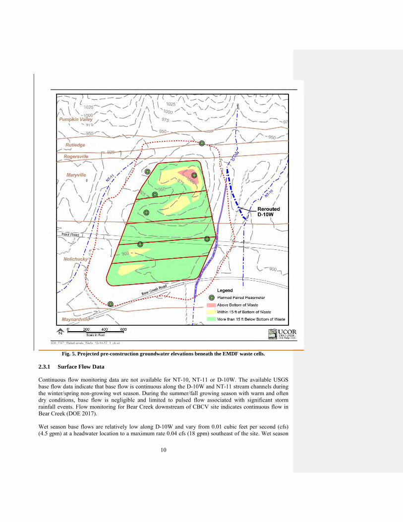


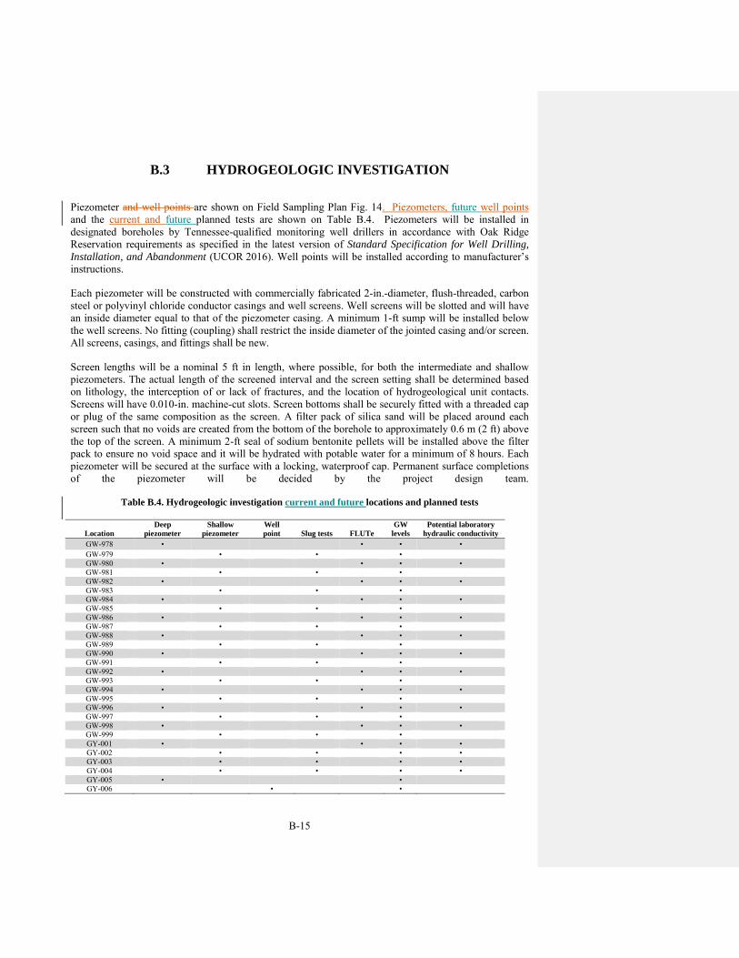


![5 201 J Surface Water Field Sampling Manual - Appendix IIIepa.ohio.gov/Portals/35/documents/SW Sampling Manual 2015 Final... · [Type text] , Surface Water Field Sampling Manual -](https://static.documents.pub/doc/80x56/5aba735e7f8b9a297f8bb65c/5-201-j-surface-water-field-sampling-manual-appendix-sampling-manual-2015-finaltype.jpg)


