236 OPTICS LETTERS / Vol. 25, No. 4 / February 15, 2000 Phase plates for wave-aberration compensation in the human eye Rafael Navarro and Esther Moreno-Barriuso Instituto de Optica ‘‘Daza de Vald´ es,’’ Consejo Superior de Investigaciones Cientif icas, Serrano 121, 28006 Madrid, Spain Salvador Bar ´ a and Teresa Mancebo ´ Area de ´ Optica, Facultade de F ´ ısica, Universidade de Santiago de Compostela, 15706 Santiago de Compostela, Galicia, Spain Received June 22, 1999 We present a method for manufacturing phase plates to compensate for the wave aberration in the human eye. The wave aberration of the eye is measured in vivo by a new laser ray-tracing method and then compensated for by a phase plate placed in front of the eye. This plate is made from a gray-level single-mask photosculpture in photoresist. Two experiments were carried out, first with an artificial eye and then with a human eye: 80% compensation for the wave aberration was achieved in both cases. 2000 Optical Society of America OCIS codes: 220.0220, 330.0330, 020.3620. In 1961 Smirnov 1 reported measurements of the overall wave aberration in the human eye obtained by means of a spatially resolved subjective refractometer. He sug- gested that ‘‘in principle, it is possible to manufacture a lens compensating the wave aberration of the eye in the complex form of the plates of errors.’’ We have veri- fied Smirnov’s suggestion experimentally by manufac- turing and testing such special lenses. These lenses consist of phase plates adapted to compensate for optical aberrations in individual eyes. Conventional opthalmic lenses can compensate for second-order aber- rations (defocus and astigmatism) only, and only re- cently was the first successful attempt at overall phase conjugation in the human eye reported. 2 In that ex- periment Liang et al. combined a Hartmann–Shack wave-front sensor and a deformable mirror, similar to those used in some astronomical telescopes. This so- phisticated system is, however, far from the idea of a special single lens, and it is hard to imagine its working outside the environment of the optical labora- tory. Special lenses were made before, not for correc- tion of the overall wavefront distortion but for partial correction of specific types of aberration (spherical, 3 coma, 4 etc.). In this Letter we report what to our knowledge are the first experimental results of manufacture and testing of customized phase plates (special lenses) for the conjugation of the overall monochromatic l 543 nmwave aberration in individual eyes. Our results, with 80% aberration compensation attained in both artificial and human eyes, constitute what we believe is the first successful implementation of Smirnov’s suggestion. The phase plate is a light single component, which permits us to build a static open-loop system for phase conjugation. The complete experiment consists of three stages that we tested independently. The first step is to measure the aberrations in the eye under test, by a laser ray-tracing (LRT) method. 5 The LRT had been described and validated previously in a series of experiments, including direct comparison with a Hartmann–Shack wave-front sensor. 6 The wave aberration is then obtained by the standard method based on least-squares fitting of the geometric aberra- tions to the derivatives of Zernike polynomials. 7 The next step is to manufacture a phase plate with Zernike coefficients of the same magnitude but opposite sign. To make the plates we applied a gray-level single-mask photosculpture in photoresist technique. 8 – 10 After passing optical tests (see below), the plate is placed in front of the eye like a spectacle lens (except that it requires careful alignment with the eye’s pupil for maximum compensation). In the third step, we mea- sure the wave aberration again to evaluate the degree of compensation attained, as a global assessment of the whole procedure. Thus there are two main techniques involved, LRT and photosculpture. The basis of the LRT method is depicted in Fig. 1. A narrow Gaussian laser beam (0.7-mm diameter) is used as a finite approximation of a ray of light. A two-dimensional laser scanner per- mits the beam to be directed to the desired coordinates at the entrance pupil plane. The aerial image A 0 of (Gaussian) spot A, formed on the retina by the beam, is collected by a CCD camera, and its centroid coor- dinates are then computed. By delivering a sequen- tial series of rays coming from the same point object and passing through a previously defined pupil sam- pling grid, we obtain a spot diagram. In this experi- ment the grid is hexagonal with 6-mm diameter and 1-mm steps (37-ray set). The effective pupil diame- ter is roughly 6.7 mm because of the f inite width of the beam. A seventh-order Zernike polynomial expansion, 35 coefficients, close to the number of samples, is used to describe the wave aberration of the eye. This set of 35 coefficients, which is the output of the measuring stage, is the input for the phase-plate manu- facturing process. For this purpose we implemented a gray-level single-mask photosculpture in photoresist technique, which is a reasonably efficient and cheap method for making micro-optics elements. We start with a flat plate that is a cleaned soda lime glass substrate spin coated with Shipley S1828 positive photoresist at 400 rpm during 30 s and prebaked at 90 ± C for 30 min. In this way we obtain a thin photo- resist film that is 12 mm thick (see Fig. 2). This 0146-9592/00/040236-03$15.00/0 2000 Optical Society of America
Phase plates for wave-aberration compensationin the human eye
Rafael Navarro and Esther Moreno-Barriuso
Instituto de Optica ‘‘Daza de Valdes,’’ Consejo Superior de Investigaciones Cientif icas, Serrano 121, 28006 Madrid, Spain
Salvador Bara and Teresa Mancebo
Area de Optica, Facultade de F ısica, Universidade de Santiago de Compostela, 15706 Santiago de Compostela, Galicia, Spain
Received June 22, 1999
We present a method for manufacturing phase plates to compensate for the wave aberration in the human eye.The wave aberration of the eye is measured in vivo by a new laser ray-tracing method and then compensated forby a phase plate placed in front of the eye. This plate is made from a gray-level single-mask photosculpture inphotoresist. Two experiments were carried out, f irst with an artif icial eye and then with a human eye: 80%compensation for the wave aberration was achieved in both cases. 2000 Optical Society of America
OCIS codes: 220.0220, 330.0330, 020.3620.
In 1961 Smirnov1 reported measurements of the overallwave aberration in the human eye obtained by means ofa spatially resolved subjective refractometer. He sug-gested that ‘‘in principle, it is possible to manufacture alens compensating the wave aberration of the eye in thecomplex form of the plates of errors.’’ We have veri-fied Smirnov’s suggestion experimentally by manufac-turing and testing such special lenses. These lensesconsist of phase plates adapted to compensate foroptical aberrations in individual eyes. Conventionalopthalmic lenses can compensate for second-order aber-rations (defocus and astigmatism) only, and only re-cently was the first successful attempt at overall phaseconjugation in the human eye reported.2 In that ex-periment Liang et al. combined a Hartmann–Shackwave-front sensor and a deformable mirror, similar tothose used in some astronomical telescopes. This so-phisticated system is, however, far from the idea ofa special single lens, and it is hard to imagine itsworking outside the environment of the optical labora-tory. Special lenses were made before, not for correc-tion of the overall wavefront distortion but for partialcorrection of specific types of aberration (spherical,3
coma,4 etc.).In this Letter we report what to our knowledge
are the first experimental results of manufacture andtesting of customized phase plates (special lenses) forthe conjugation of the overall monochromatic �l �543 nm� wave aberration in individual eyes. Ourresults, with 80% aberration compensation attainedin both artificial and human eyes, constitute whatwe believe is the first successful implementation ofSmirnov’s suggestion. The phase plate is a light singlecomponent, which permits us to build a static open-loopsystem for phase conjugation.
The complete experiment consists of three stagesthat we tested independently. The first step is tomeasure the aberrations in the eye under test, bya laser ray-tracing (LRT) method.5 The LRT hadbeen described and validated previously in a seriesof experiments, including direct comparison with aHartmann–Shack wave-front sensor.6 The waveaberration is then obtained by the standard method
0146-9592/00/040236-03$15.00/0
based on least-squares fitting of the geometric aberra-tions to the derivatives of Zernike polynomials.7 Thenext step is to manufacture a phase plate with Zernikecoefficients of the same magnitude but opposite sign.To make the plates we applied a gray-level single-maskphotosculpture in photoresist technique.8 – 10 Afterpassing optical tests (see below), the plate is placedin front of the eye like a spectacle lens (except thatit requires careful alignment with the eye’s pupil formaximum compensation). In the third step, we mea-sure the wave aberration again to evaluate the degreeof compensation attained, as a global assessment of thewhole procedure.
Thus there are two main techniques involved, LRTand photosculpture. The basis of the LRT methodis depicted in Fig. 1. A narrow Gaussian laser beam(0.7-mm diameter) is used as a finite approximation ofa ray of light. A two-dimensional laser scanner per-mits the beam to be directed to the desired coordinatesat the entrance pupil plane. The aerial image A0 of(Gaussian) spot A, formed on the retina by the beam,is collected by a CCD camera, and its centroid coor-dinates are then computed. By delivering a sequen-tial series of rays coming from the same point objectand passing through a previously defined pupil sam-pling grid, we obtain a spot diagram. In this experi-ment the grid is hexagonal with 6-mm diameter and1-mm steps (37-ray set). The effective pupil diame-ter is roughly 6.7 mm because of the finite width of thebeam. A seventh-order Zernike polynomial expansion,35 coefficients, close to the number of samples, is usedto describe the wave aberration of the eye.
This set of 35 coefficients, which is the output of themeasuring stage, is the input for the phase-plate manu-facturing process. For this purpose we implementeda gray-level single-mask photosculpture in photoresisttechnique, which is a reasonably efficient and cheapmethod for making micro-optics elements. We startwith a f lat plate that is a cleaned soda lime glasssubstrate spin coated with Shipley S1828 positivephotoresist at 400 rpm during 30 s and prebaked at90 ±C for 30 min. In this way we obtain a thin photo-resist film that is �12 mm thick (see Fig. 2). This
Fig. 1. LRT method: A narrow laser pencil is def lectedby a computer-controlled two-dimensional laser scanner.The beam, after passing through a beam splitter and agiven point at the pupil plane, forms a small spot of light atthe retina. The position offset, AO, between this spot andthat formed by the chief ray is the aberration of that ray.A CCD camera records the image of each spot to computeits centroid. PBS, polarization beam splitter.
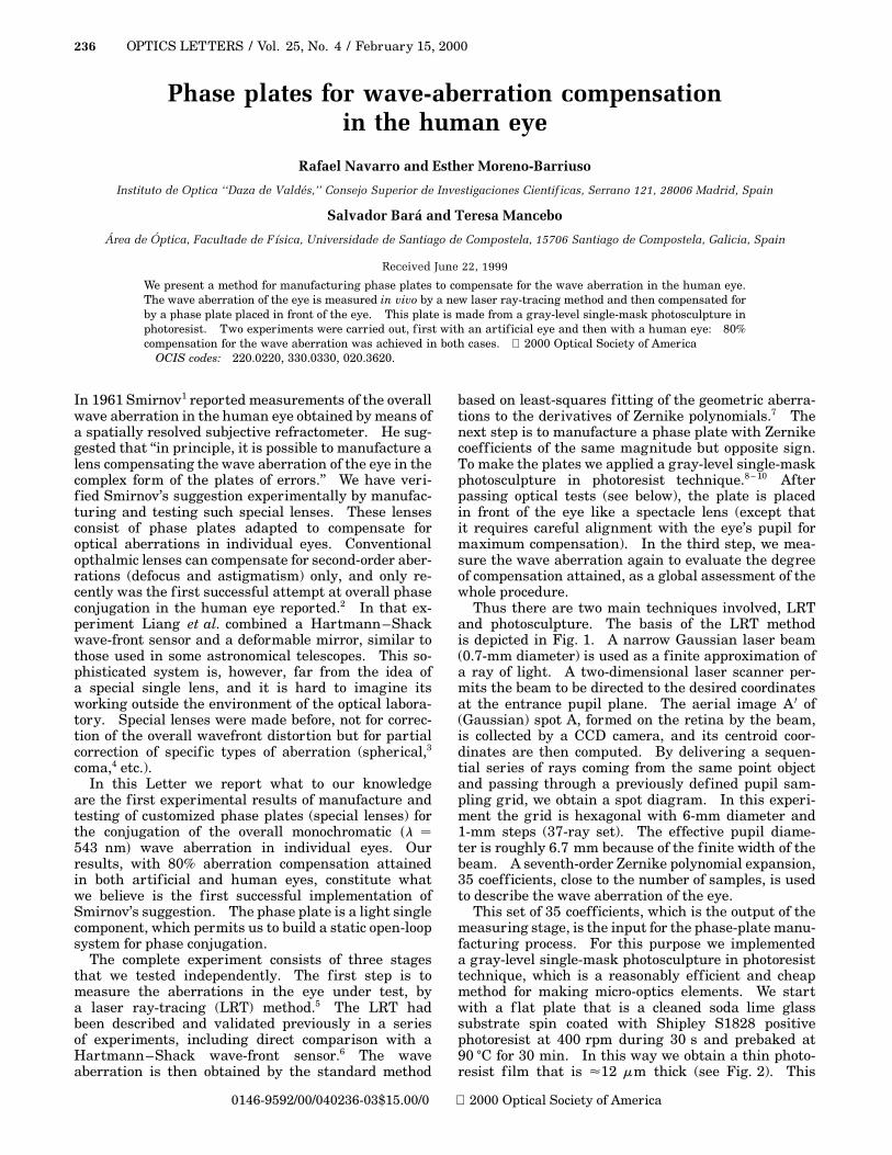
plate is exposed to ultraviolet radiation (Fig. 2)through a variable-transmittance mask that encodesthe desired phase. We fabricated the mask by pho-toreducing a hard copy of the (negative) patternobtained with a conventional ink injection printer.After development, the variable-irradiance dose ab-sorbed by the photoactive compound gives rise toa three-dimensional continuous profile of unequaldepth. A depth difference Dz will produce a phaselag 2p�n 2 1�Dz�l, where n is the refractive index ofthe photoresist. By a careful calibration of the entireprocess, which has shown reasonably good linearity,it is possible to obtain a plate that will produce aphase disturbance that is conjugated (opposite) tothe wave aberration of the eye. Hence the resultantphase plate can potentially act as a correcting ele-ment. We verify that the phase generated by theplate is close to the nominal desired value by usinga Mach–Zehnder interferometer. At the bottom ofFig. 3 we compare the ideal reference (left) and theresultant (right) interferograms measured for theplate used for our subject’s eye. We can see that,despite its granular appearance, which is due to manu-facturing noise and errors, there is a reasonableoverall similarity between the interferogram (phaseof the resulting plate) and the nominal design value.
Nevertheless, we measured the wave aberration ofthe plate (alone) by laser ray tracing. The resultantrms difference between the measured and the nominalwave aberration was 0.25 mm in this case (Fig. 3).The resultant plate is placed at a distance of 10 mm infront of the eye (between the eye and the beam splitterin Fig. 1) and carefully aligned with the optical axis ofthe system.
The first experiment was carried out with an arti-f icial eye consisting of a high-quality, low-numerical-aperture achromatic doublet lens and a white diffusingsurface, placed at the focal plane of the lens, acting asan artificial retina. We introduced wave-front distor-tions into this ideal eye by placing an aberrating plate(soda lime glass deformed by heating) close to the lens.The measured rms wave-front error was 0.79 mm ini-tially but decreased to 0.16 mm after insertion of thecorrecting plate, that is, an 80% compensation.
The results of the second experiment (right eye ofsubject EM) are shown in Fig. 3. The degree of com-pensation (compare the two top figures) is again 80%.Such a substantial compensation, which includesthird- and higher-order aberrations, confirms thataberrations can be corrected in living human eyes bycustomized phase plates. This result looks promising,because further improvements of the method are stillpossible (especially in the manufacture of the plates).
There are several limitations that are inherent inall phase-conjugation methods: Compensation is pos-sible only for a limited visual field and for a givenaccommodative state. In addition, the alignmentbecomes critical in the compensation for high-orderterms. Our method also has some specific advantagesand drawbacks. The main advantages are the mod-erately low cost and the high spatial resolution. Thedrawbacks are the specificity of a plate for a singlesubject or condition (unlike adaptive devices) and the
Fig. 2. Manufacture of phase plates. The photoresist de-posited upon a glass substrate is exposed to UV radiationthrough a gray-level transmission mask. After develop-ing, we obtained the desired profile.
Fig. 3. Top, wave aberration (W. A.) of subject EM (righteye) before (left) and after (right) compensation. Thecontour-line step is 0.5 mm. Bottom, ideal (left) and real(right) phases of the plate, measured by a Mach–Zehnderinterferometer; the rms difference between the design(ideal) and the manufactured plate is 0.25 mm.
lower transparency of the photoresist compared withoptical glass (although it would be possible to manufac-ture glass replicas by standard techniques).
For subject EM the rms residual aberration aftercompensation was the same as the rms differencebetween the nominal and the measured phases of theplate �0.25 mm�. This suggests that inaccuracies inthe manufacture of the plate were the main limitationson the compensation attainable in this case. Manufac-ture has two main practical constraints: (1) Accuracyis limited by the minimum structure that we can sculptwith some reliability. (2) The maximum magnitudeof aberration that we can compensate for is limited,because as we increase the thickness of the photoresistlayer it becomes harder to control the layer’s f latness.
Overcoming these two problems has contradictorysolutions, but both accuracy and dynamic range arenecessary because low-order aberrations in the eye canhave high values (several wavelengths), whereas theirmagnitude tends to decay rapidly with order.11 Thuscompensating for low (high values) and high (lowvalues) orders simultaneously is diff icult. Neverthe-less, considering that second-order aberrations can becompensated for with conventional lenses, and that thecontribution of higher orders is small in general, itseems more efficient to make plates for correctinga more limited set of aberrations (third, fourth, andpossibly fifth orders). In this case, because the re-quired dynamic range will be much lower this subsetof aberrations could be compensated for with higheraccuracy. In a next step, we intend also to explorethe possibility of using an ophthalmic lens (adapted tothe eye’s prescription) as the substrate upon which todeposit the photoresist to obtain a monolithic singleoptical element for high-accuracy compensation.
This research was supported by the ComisionInterministerial de Ciencia y Tecnologıa of Spain,grant TIC98-0925-C02. R. Navarro’s e-mail addressis [email protected].
References
1. M. S. Smirnov, Biofizika 6, 687 (1961) [Byophysics 6,766 (1962)].
2. J. Liang, D. R. Williams, and D. T. Miller, J. Opt. Soc.Am. A 14, 2884 (1997).
3. N. Chateau, A. Blanchard, and D. Baude, J. Opt. Soc.Am. A 15, 2589 (1998).
4. N. Lopez, H. C. Howland, B. Howland, N. Charman,and R. Applegate, J. Opt. Soc. Am. A 15, 2563 (1998).
5. R. Navarro and M. A. Losada, Optom. Vision Sci. 74,540 (1997).
6. R. Navarro and E. Moreno-Barriuso, Opt. Lett. 24, 951(1999).
7. D. Malacara, Optical Shop Testing, 2nd ed. (Wiley,New York, 1992).
8. H. Andersson, M. Ekberg, S. Hard, S. Jakobson, M.Larsson, and T. Nilsson, Appl. Opt. 29, 4259 (1990).
9. D. R. Purdy, Pure Appl. Opt. 3, 167 (1995).10. T. J. Suleski and D. C. O’Shea, Appl. Opt. 34, 7507
(1995).11. J. Liang and D. R. Williams, J. Opt. Soc. Am. A 14,