DU-AG-0018-23 Rev H 12/4/13 GCX Corp Page 1 of 8 3875 Cypress Drive Petaluma, CA 94954 800.228.2555 707.773.1100 Fax 707.773.1180 www.gcx.com Installation Guide Philips IntelliVue MP5/20/30/40/50/60/70, MX400/450/500/550/600/700/800 M-Series Arm Rail Mount Kit The purpose of this guide is to: 1. Describe attachment of Table Top Mount to Mounting Adapter on Arm (page 2). 2. Describe attachment of Down Post to M-Series Arm (page 2). 3. Describe mounting of Arm on rail (pages 3 – 6). 4. Describe mounting of Flexible Module Server (FMS) on Down Post (page 7). 5. Describe operation and adjustment of M-Series Arm (pages 7 – 8) Parts Reference The following parts and hardware are included in this installation kit (hardware not shown): Tools Required: Phillips screwdriver, 5/32'' [4mm] and 3/16'' hex wrenches (provided). Caution - Before mounting the Arm: 1. Ensure that the weight of the device being mounted does not exceed the load rating of your M-Series Arm. Check the "Max Load" rating label located on top of the arm at the Slide pivot point. It is not recommended that this arm be used for weights outside of this range. 2. If assistance is needed regarding an application, please contact a GCX product specialist at (800) 228-2555. Item # Description Qty 1 M-Series Arm (see pg. 3 for Rail Clamp Parts) 1 2 6'' Down Post 1 3 #10-32 x 3/8'' SHCS 3 4 M6 x 8mm Flat Head Machine Screw (FHMS) 2 5 M6 x 12mm FHMS 1 6 5/32'' [4mm] Hex Wrench 1 *7 Spacer 1 *8 M6 x 16mm Pan Head Machine Screw (PHMS) 2 *See non-Table Top Mount" on page 7 for use of these parts. Table Top Mount (Supplied by Philips) Spacer 6'' Down Post M-series Arm
Philips IntelliVue MP5/20/30/40/50/60/70, MX400/450/500/550/600/700/800 M-Series Arm Rail Mount Kit
The purpose of this guide is to:
1. Describe attachment of Table Top Mount to Mounting Adapter on Arm (page 2). 2. Describe attachment of Down Post to M-Series Arm (page 2). 3. Describe mounting of Arm on rail (pages 3 – 6). 4. Describe mounting of Flexible Module Server (FMS) on Down Post (page 7). 5. Describe operation and adjustment of M-Series Arm (pages 7 – 8)
Parts Reference
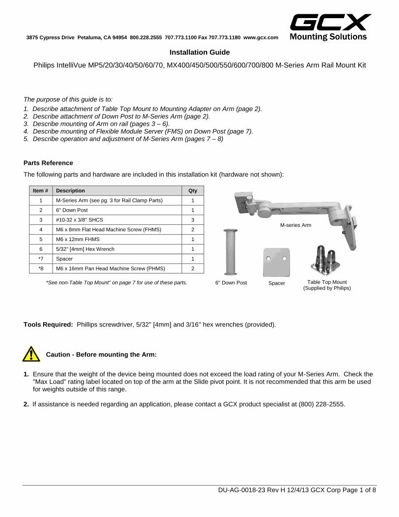
The following parts and hardware are included in this installation kit (hardware not shown):
1. Ensure that the weight of the device being mounted does not exceed the load rating of your M-Series Arm. Check the "Max Load" rating label located on top of the arm at the Slide pivot point. It is not recommended that this arm be used for weights outside of this range.
2. If assistance is needed regarding an application, please contact a GCX product specialist at (800) 228-2555.
Item # Description Qty
1 M-Series Arm (see pg. 3 for Rail Clamp Parts) 1
2 6'' Down Post 1
3 #10-32 x 3/8'' SHCS 3
4 M6 x 8mm Flat Head Machine Screw (FHMS) 2
5 M6 x 12mm FHMS 1
6 5/32'' [4mm] Hex Wrench 1
*7 Spacer 1
*8 M6 x 16mm Pan Head Machine Screw (PHMS) 2
*See non-Table Top Mount" on page 7 for use of these parts.
Table Top Mount (Supplied by Philips)
Spacer 6'' Down Post
M-series Arm
DU-AG-0018-23 Rev H 12/4/13 GCX Corp Page 2 of 8
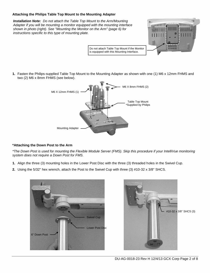
Attaching the Philips Table Top Mount to the Mounting Adapter 1. Fasten the Philips-supplied Table Top Mount to the Mounting Adapter as shown with one (1) M6 x 12mm FHMS and
two (2) M6 x 8mm FHMS (see below). *Attaching the Down Post to the Arm
*The Down Post is used for mounting the Flexible Module Server (FMS). Skip this procedure if your IntelliVue monitoring system does not require a Down Post for FMS. 1. Align the three (3) mounting holes in the Lower Post Disc with the three (3) threaded holes in the Swivel Cup.
2. Using the 5/32'' hex wrench, attach the Post to the Swivel Cup with three (3) #10-32 x 3/8'' SHCS.
#10-32 x 3/8'' SHCS (3)
6'' Down Post
Lower Post Disc
Swivel Cup
Do not attach Table Top Mount if the Monitor is equipped with this Mounting Interface.
M6 X 8mm FHMS (2)
M6 X 12mm FHMS (1)
Mounting Adapter
Table Top Mount *Supplied by Philips
Installation Note: Do not attach the Table Top Mount to the Arm/Mounting Adapter if you will be mounting a monitor equipped with the mounting interface shown in photo (right). See "Mounting the Monitor on the Arm" (page 6) for instructions specific to this type of mounting plate.
DU-AG-0018-23 Rev H 12/4/13 GCX Corp Page 3 of 8
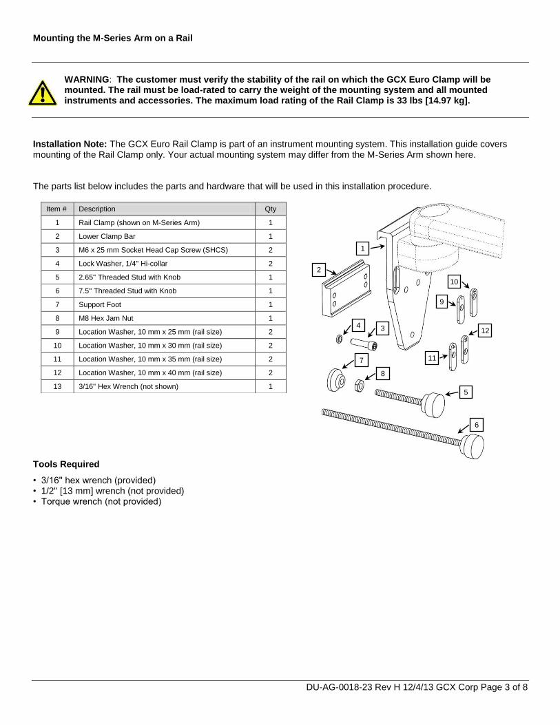
Mounting the M-Series Arm on a Rail
WARNING: The customer must verify the stability of the rail on which the GCX Euro Clamp will be mounted. The rail must be load-rated to carry the weight of the mounting system and all mounted instruments and accessories. The maximum load rating of the Rail Clamp is 33 lbs [14.97 kg].
Installation Note: The GCX Euro Rail Clamp is part of an instrument mounting system. This installation guide covers mounting of the Rail Clamp only. Your actual mounting system may differ from the M-Series Arm shown here. The parts list below includes the parts and hardware that will be used in this installation procedure.
In this procedure the Rail Clamp is being mounted on a 10 mm x 25 mm rail.
3. Insert one (1) Location Washer in each Rail Clamp slot as shown, dots pointing upward.
4. Install Lower Clamp Bar by threading two M6 x 25 mm
SHCS (with 1/4'' lock washers) through Location Washers and into lower set of mounting holes as shown. Installation Note: See page 5 for instruction regarding
installation of Lower Clamp Bar on larger sized rails.
1. Determine size of rail and select appropriate set of Location Washers. Number of dots indicates size of rail. Location Washers
must be installed with dots in upward ↑ position.
Lower Clamp Bar
• M6 x 25 mm SHCS (2) • 1/4'' Lock Washer (2)
2. Hook Rail Clamp over rail.
10 x 25 mm Rail
(1 dot) 10 x 30 mm Rail
(2 dots)
10 x 35 mm Rail
(3 dots)
10 x 40 mm Rail
(4 dots)
WARNING! Ensure that the Location Washers selected match the rail size before installing the Rail Clamp. The Location Washers must be installed with dot pattern upward. The use of incorrect Location
Washers or incorrect orientation of Location Washers could result in product failure or injury.
DU-AG-0018-23 Rev H 12/4/13 GCX Corp Page 5 of 8
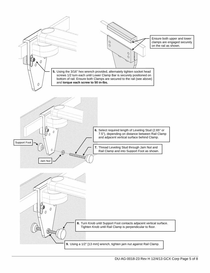
8. Turn Knob until Support Foot contacts adjacent vertical surface.
Tighten Knob until Rail Clamp is perpendicular to floor.
9. Using a 1/2'' [13 mm] wrench, tighten jam nut against Rail Clamp.
5. Using the 3/16'' hex wrench provided, alternately tighten socket head
screws 1/2 turn each until Lower Clamp Bar is securely positioned on bottom of rail. Ensure both Clamps are secured to the rail (see above) and torque each screw to 50 in-lbs.
Ensure both upper and lower clamps are engaged securely on the rail as shown.
7. Thread Leveling Stud through Jam Nut and
Rail Clamp and into Support Foot as shown.
6. Select required length of Leveling Stud (2.65'' or
7.5''), depending on distance between Rail Clamp and adjacent vertical surface behind Clamp.
Support Foot
Jam Nut
DU-AG-0018-23 Rev H 12/4/13 GCX Corp Page 6 of 8
Mounting on 35mm to 40mm Rail Heights
Mounting the Monitor on the Arm
Table Top Mount
Mount the monitor in accordance with the Philips Table Top Mount instruction sheet. Non-Table Top Mount
1. Fit Spacer into recessed area on top of Mounting Adapter (below). Ensure Spacer remains between Mounting Adapter and monitor.
2. Insert two (2) M6 x 16mm PHMS through bottom of Mounting Adapter and thread into mounting holes in bottom of monitor (right).
M6 x 16mm PHMS (2)
Use upper mounting holes in Lower Clamp Bar when
mounting on rails 35 mm to 40 mm in height.
Use 10 mm x 35 mm or 10 mm x 40 mm Location Washer.
10 x 35 mm Rail
(3 dots)
10 x 40 mm Rail
(4 dots)
Mounting the MX400/450/500/550 Monitor (Fixed Mount Adapter)
Mount the monitor in accordance with separate Installation Guide DU-PH-0073-15 provided with the Mounting Adapter, ordered separately.
Spacer Mounting Adapter
DU-AG-0018-23 Rev H 12/4/13 GCX Corp Page 7 of 8
Mounting the Flexible Module Server (FMS) on the Down Post
Installation Note: This procedure is not required if Down Post has not been installed. 1. Attach the FMS to the Down Post by placing the Clamp around the Post and tightening the knob.
M-Series Arm Operation and Adjustment
Swivel & Swivel Tension
1. In most configurations, the mounted device will swivel at the end of the Arm. To rotate the device simply push or pull the corners of the device.
2. To adjust the swivel tension, tighten or loosen the Swivel Tension Nut with a 1/2 [13 mm] socket wrench.
Warning: Swivel tension nut must be torqued to a minimum of 20 in-lbs [2.3 N-m].
.
Down Post
FMS
Clamp
Swivel Tension Nut
Tilt & Tilt Tension
1. Loosen the Adjustment Lever (if included).
2. Grasp top and bottom of device and tilt it to desired angle.
3. Using a 5/32'' hex wrench, equally tighten or loosen the two (2) Tilt Tension Screws.
Warning: Tilt tension screws must be torqued to a minimum of 35 in-lbs [4.0 N-m].
Tilt Tension Screws (2)
DU-AG-0018-23 Rev H 12/4/13 GCX Corp Page 8 of 8
Flexible Cable Covers
Pivot Tension Bolt
Positioning Arm in Channel
Pivoting the Arm
1. To pivot the Arm at the Slide, simply push on the side of the Arm or mounted instrument.
2. To adjust pivot tension, loosen or tighten the Pivot Tension Bolt
using a 1/2" [13 mm] socket driver. Cable Management
An open cavity beneath the arm (with flexible cable covers) allows management of cables between the front and rear of the arm.
Routine Maintenance
Periodically inspect all hardware associated with the mounting system. Tighten as required for optimal operation and safety. Cleaning the Mounting Assembly
1. The mounting assembly may be cleaned with most mild, non-abrasive solutions commonly used in the hospital environment (e.g. diluted bleach, ammonia, or alcohol solutions).
2. The surface finish will be permanently damaged by strong chemicals and solvents such as acetone or
trichloroethylene. 3. Do not use Steel wool or other abrasive material. 4. Damage caused by the use of unapproved substances or processes will not be warranted. We recommend testing of
any cleaning solution on a small area of the arm that is not visible to verify compatibility. 5. Never submerge or allow liquids to enter the arm. Wipe any cleaning agents off of the arm immediately using a water-
dampened cloth. Dry the arm thoroughly after cleaning. CAUTION: GCX makes no claims regarding the efficacy of the listed chemicals or processes as a means for controlling infection. Consult your hospital’s infection control officer or epidemiologist. To clean or sterilize mounted devices or accessory equipment, refer to the specific instructions delivered with those products.