• 4-123 www.powercommander.com • IgnitionQuickShifter-StandAloneUnit-1
• PLEASEREADALLDIRECTIONSBEFORESTARTINGINSTALLATION
• 2191MendenhallDriveNorthLasVegas,NV89081(800)992-4993www.powercommander.com
08-12 Kawasaki EX250
I ns ta l l a t i on I ns t ruc t i ons
PartsList
• 1IgnitionQuickshifterUnit• 1ShiftSensor(push)• 1ShiftRod• 1InstallationGuide• 2DynojetDecal• 4CableTies• 1Velcrostrip• 1AlcoholSwab• 1Posi-tap
(CarburetedModelsOnly)
• 4-123 www.powercommander.com • IgnitionQuickShifter-StandAloneUnit-2
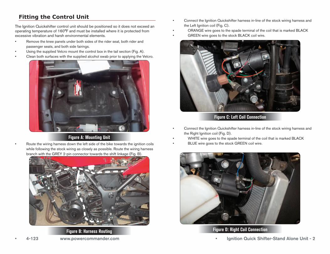
• Removethekneepanelsunderbothsidesoftheriderseat,bothriderandpassengerseats,andbothsidefairings.
• UsingthesuppliedVelcromountthecontrolboxinthetailsection(Fig.A).• CleanbothsurfaceswiththesuppliedalcoholswabpriortoapplyingtheVelcro.
Fitting the Control Unit
TheIgnitionQuickshiftercontrolunitshouldbepositionedsoitdoesnotexceedanoperatingtemperatureof160°Fandmustbeinstalledwhereitisprotectedfromexcessivevibrationandharshenvironmentalelements.
• Routethewiringharnessdowntheleftsideofthebiketowardstheignitioncoilswhilefollowingthestockwiringascloselyaspossible.RoutethewiringharnessbranchwiththeGREY2-pinconnectortowardstheshiftlinkage(Fig.B).
Figure A: Mounting Unit
Figure B: Harness Routing
• ConnecttheIgnitionQuickshifterharnessin-lineofthestockwiringharnessandtheLeftIgnitioncoil(Fig.C).
• ORANGEwiregoestothespadeterminalofthecoilthatismarkedBLACK• GREENwiregoestothestockBLACKcoilwire.
Figure C: Left Coil Connection
• ConnecttheIgnitionQuickshifterharnessin-lineofthestockwiringharnessandtheRightIgnitioncoil(Fig.D).
• WHITEwiregoestothespadeterminalofthecoilthatismarkedBLACK• BLUEwiregoestothestockGREENcoilwire.
Figure D: Right Coil Connection
• 4-123 www.powercommander.com • IgnitionQuickShifter-StandAloneUnit-3
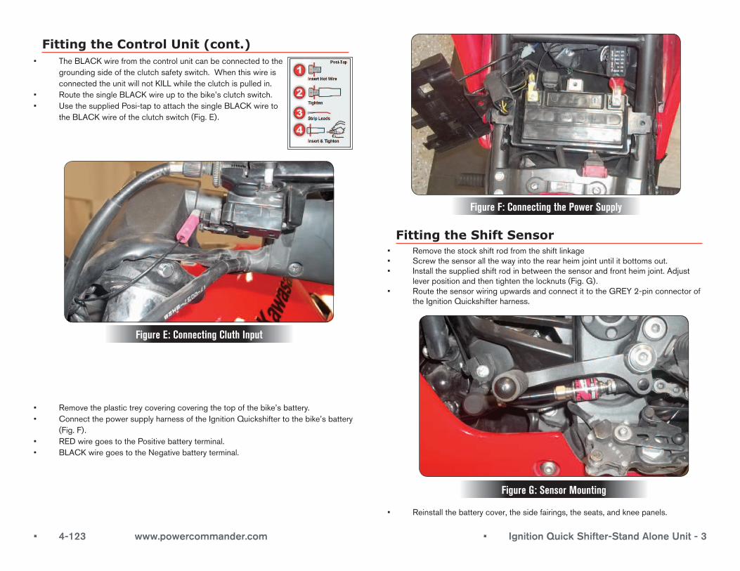
Fitting the Control Unit (cont.)• TheBLACKwirefromthecontrolunitcanbeconnectedtothe
groundingsideoftheclutchsafetyswitch.WhenthiswireisconnectedtheunitwillnotKILLwhiletheclutchispulledin.
• RoutethesingleBLACKwireuptothebike’sclutchswitch.• UsethesuppliedPosi-taptoattachthesingleBLACKwireto
theBLACKwireoftheclutchswitch(Fig.E).
Figure E: Connecting Cluth Input
• Removetheplastictreycoveringcoveringthetopofthebike’sbattery.• ConnectthepowersupplyharnessoftheIgnitionQuickshiftertothebike’sbattery
(Fig.F).• REDwiregoestothePositivebatteryterminal.• BLACKwiregoestotheNegativebatteryterminal.
Figure F: Connecting the Power Supply
Fitting the Shift Sensor• Removethestockshiftrodfromtheshiftlinkage• Screwthesensorallthewayintotherearheimjointuntilitbottomsout.• Installthesuppliedshiftrodinbetweenthesensorandfrontheimjoint.Adjust
leverpositionandthentightenthelocknuts(Fig.G).• RoutethesensorwiringupwardsandconnectittotheGREY2-pinconnectorof
theIgnitionQuickshifterharness.
Figure G: Sensor Mounting
• Reinstallthebatterycover,thesidefairings,theseats,andkneepanels.
• 4-123 www.powercommander.com • IgnitionQuickShifter-StandAloneUnit-4
Quickshifter System Operation
TousetheIgnitionQuickshifter,makeafullandpositivegearshiftwithyourfootinanupshiftdirectionwithoutusingtheclutchorrollingthethrottle.
Note:Thegearlevermustreturnfullytotherestpositionbeforethesystemresetsitselfforthenextgearselection.
ThestatusLEDwillilluminatesolidgreenwhenevertheQuickshiftersensorisinthetriggerposition.ThisstatusLEDwillflashinunisonwiththeenginewhenevertheengineisrunningandifthereisanignitioncoil/RPMsignalwhichisrequiredforrunningmode.
Therewillbenointerrupt/quickshiftbelow2500RPM.
Theunitcomeswithasetshiftkillinterrupttime.
Troubleshooting
Nopowerup Checkforincorrectconnections,blownfuses,poorbatteryterminalconnections,andseveredortrappedwires.
Noquickshifterinterrupt CheckforcorrectIgnitionQuickshifterpowersupply.Verifythesensoroutputsignalandthequickshifterparametersandprogramminghasbeencarriedout.Checkforlossoftacho/RPMsignal.Checkforseveredortrappedwires.
Noquickshifteroperation Verifythequickshifterparametersandprogramminghavebeencarriedout.Checkforlossoftacho/RPMsignal.Checkforseveredortrappedwires.
Enginemisfire Verifythecontrolunitmountingpositionandcheckforisolationfromvibration.Checkplugandplayconnections.Verifyignitioncoiltypeandsuitabilityandiftheignitioncoiladapterconnectorsrequirefitting.Verifysensoroutputsignal.
Tuner Mode/Setting the Base Interrupt Duration
• ToenterTunerMode,pulltheclutchleverinorholdtheblackclutchswitchlock-outwiretoground/chassis.
• MovethegearleverintoatriggerpositionwherethestatusLEDilluminatessolidgreenandholdinthispositionforsixsecondsuntilthegreenstatusLEDchangestoredtoindicateyouhaveenteredTunerMode.
• Releasetheclutchleverorblackclutchswitchlock-outwirefromground/chassisandreleasethegearlever.
• Onceyouhavefinishedyoursetting,theblackclutchswitchlock-outwireshouldbetapedupandsecuredifitisnotabletobeconnectedtothevehicleclutchswitchitself.
• FactoryDefaultInterruptDurationissetto66ms(milliseconds)andisequaltotenredstatusLEDflashes.Itshouldbenotedthatthisisjustthebasesettingandcanbeadjustedifdesired.ThisadvancedQuickshifterSystemwillvaryinterruptdurationsdependingonengineparameters.
• Toalter/increasethebaseinterruptdurationby2ms,momentarilymovethegearlevertothetriggerpositionwhichcanbeseenbytheflashingredstatusLEDchangingtolightingsolidredwhileinthetriggerposition.
• TheflashingredstatusLEDwillnowflasheleventimesoncethegearleverhasbeenreleasedtoindicatethe2msincreasefrom66msto68ms.
• Eachtimethegearleverismomentarilymovedtothetriggerpositiontheinterruptdurationwillincreaseby2msuptoamaximumof20redstatusLEDflashesor86ms.Afterthispoint,furthermomentarytriggerswilltaketheinterrupttimebackdowntooneredstatusLEDflashor48msinterruptduration.Theinterruptdurationcanbeincreasedagainandsoonuntilthedesiredbaseinterruptdurationisreached.
• ToexitTunerMode,holdthegearleverinthetriggerpositionforfoursecondstosaveandauthenticatethesettingswheretheflashingredstatusLEDwillrevertbacktogreen.
General Product Warranty and Servicing
AswithanytechnicalequipmentofthisnatureitisstronglyrecommendedthattheexposedproductitemssuchastheIgnitionQuickshifterandGP/LSsensorsshouldbekeptcleanandcheckedregularly.Theseunitsshouldbecleanedbyremovingexcessdustwithaclothorsmallnylonbrush.Avoidusingajetwashwithinthevicinityoftheseunits.
Productsfittedtomotocross,supermoto,kart,andoffroadbuggyapplicationsarenotcoveredbythewarranty.
• ThisDynojetproductiscoveredbya12monthwarrantyfromthedateofpurchaseagainstanydefectsinmaterialsorworkmanship.
• IfanydefectshouldoccurduringthewarrantyperiodtheproductshouldbereturnedtoDynojetResearch,oralternativelytotheplaceofpurchasealongwithproofofpurchase.Thiswarrantydoesnotcoverreturnshippingcosts.
• DynojetResearchwillexaminetheproductandifitisfoundtobedefectiveduetofaultymaterialsorbadworkmanshipwill,withoutcharge,repairorreplacetheproductattheirdiscretion.
• Iftheproductcoveredbythiswarrantyisdamagedduetoaccidents,misuse,modificationorunauthorizedrepair,shorteningofcables,brokenweatherproofsealsduetocableexitbending/pullingorincorrectelectricalconnectionsthenthiswarrantybecomesvoid.
• Thiswarrantyispersonaltothepurchaserandisnottransferable.
• ProductsreturnedtoDynojetResearchshouldbepackedcarefullytoavoiddamageintransit.Pleaseincludedetailsofthefaulttogetherwithyourname,addressandcontacttelephonenumbers.