PONTIFICAL CATHOLIC UNIVERSITY OF RIO GRANDE DO SUL SCHOOL OF TECHNOLOGY COMPUTER ENGINEERING AN FPGA IMPLEMENTATION FOR CONVOLUTIONAL NEURAL NETWORK GUILHERME DOS SANTOS KOROL End-of-term work submitted to the Pontifical Catholic University of Rio Grande do Sul in partial fullfillment of the requirements for the degree of Bachelor in Computer Engineering. Advisor: Prof. Dr. Fernando Gehm Moraes Porto Alegre 2019
Transcript
PONTIFICAL CATHOLIC UNIVERSITY OF RIO GRANDE DO SULSCHOOL OF TECHNOLOGYCOMPUTER ENGINEERING
AN FPGA IMPLEMENTATIONFOR CONVOLUTIONAL
NEURAL NETWORK
GUILHERME DOS SANTOS KOROL
End-of-term work submitted to thePontifical Catholic University of RioGrande do Sul in partial fullfillment of therequirements for the degree of Bachelorin Computer Engineering.
Advisor: Prof. Dr. Fernando Gehm Moraes
Porto Alegre2019
ACKNOWLEDGMENTS
I want to express my gratitude to all those that made this work possible.
First, to my family that has always supported me. This was only possible becauseyou were there. To Iris, Ricardo, and Leo my most sincere thank you. To Joice, who readthis document with me so many times, thank you for your love and support.
Second, to all my colleagues from GAPH (Grupo de Apoio ao Projeto de Hardware)that offered suggestions and expertise. There were times that your help was crucial to theprogress of the project. To professor Marcon, Cataldo, and Ramon to whom with I had myfirst research experience, thank you. To the two that were by my side (literally, as their desksare next to mine), Leonardo and Tanauan, our technical discussions deserve my greatestappreciation.
Last, to my advisor that, untiringly, engaged in endless meetings. Your bits ofadvice, I will take with me. Thank you.
UMA IMPLEMENTAÇÃO EM FPGA PARA REDES NEURAISCONVOLUCIONAIS
RESUMO
Avanços recentes em plataformas de hardware impulsionam o uso de Redes Neu-rais Convolucionais na resolução de problemas nas mais diversas áreas, tais como Proces-samento de Linguagem Natural e Visão Computacional. Com os melhoramentos nos al-goritmos envolvidos na aprendizagem e inferência de Redes Neurais Convolucionais, umagrande quantidade de arquiteturas dedicadas em hardware foram propostas para provermaior desempenho com custos reduzidos em área e consumo energético. Em especial,os altos níveis de exigência em termos de largura de banda e poder de processamentodesafiam os projetistas a criarem estruturas de Redes Neurais Convolucionais eficientes,e passíveis de serem implementadas em ASICs e FPGAs. Esse trabalho tem por obje-tivo implementar, especificamente em plataformas reconfiguráveis (dispositivos FPGA), umestudo de caso de Rede Neural Convolucional, a Alexnet. Adicionalmente, o trabalho pro-põe a avaliação frente a uma versão em software simulada para um ambiente baseado emprocessador ARM.
AN FPGA IMPLEMENTATION FOR CONVOLUTIONAL NEURALNETWORK
ABSTRACT
Recent advances in hardware platforms boosted the use of Convolutional NeuralNetworks to solve problems in several fields such as Computer Vision and Natural Lan-guage Processing. With the improvements of algorithms involved in learning and inferenc-ing for Convolutional Neural Networks, a huge amount of dedicated hardware architectureshave been proposed to provide high performance at low energy and area costs. Notably,requirements in bandwidth and processing power have challenged architects to find struc-tures that allow modern Convolutional Neural Networks to be embedded into ASICs and FP-GAs. This work aims to implement a Convolutional Neural Network case study, the Alexnet,targeting configurable (FPGA devices). Additionally, it proposes an evaluation against anARM-simulated software version.
In artificial intelligence, deep learning is getting much attention from industry andacademia. The attention comes mainly from recent advances in hardware that providedroom for complex algorithms that run in acceptable time, making it possible to recover mean-ing from the enormous quantity of data made available every day. Many problems regardingthe hardware architectures that are being developed for this kind of use remain open.
Nowadays, the number of applications using CNNs is countless. The two mostcommon fields of application are Natural Language Processing and Computer Vision. Con-volutional Neural Networks have shown a great deal of improvement on audio [Hershey et al.,2017], video [Karpathy et al., 2014], and image classification [Russakovsky et al., 2015], aswell as segmentation [Girshick et al., 2014], scene labeling [Pinheiro and Collobert, 2014],and face recognition [Lawrence et al., 1997]. There are even networks that achieve betterthan human-level performance in some tasks such as the ResNet that in 2015 achieved er-ror rates lower than human experts in image classification [He et al., 2016]. Unfortunately,this performance comes at a cost. The algorithms employed by the most modern neural net-works require high memory bandwidth and extensive use of computational resources [Szeet al., 2017].
To mitigate the memory and performance bottlenecks created by recent CNNs,a tremendous quantity of hardware architectures have been proposed by industry and re-search communities. For example, Microsoft created the Project Catapult, developing FP-GAs accelerators for its cloud servers in [Ovtcharov et al., 2015, Putnam et al., 2016,Caulfield et al., 2016]. Google invested in the development of a series of ASICs for deeplearning processing known as the Tensor Processing Unit [Jouppi et al., 2017]. ARM pre-sented the ARM Machine Learning Processor and the Object Detection Processor [Zhuet al., 2018]. Interestingly, Movidius, an Intel company, has embedded a Deep Neural Net-work (DNN) prototyping tool into a USB stick for rapid development [Intel Corp., 2015]. More-over, many startups appeared. To mention a few, Graphcore developed the Intelligence Pro-cessing Unit [Stokel-Walker, 2018], NovuMind has shown NovuTensor and NovuBrain chipsfor deep learning [NovuMind, 2018], Ceva introduced the Intelligent Vision Processor [Ceva,2015].
Memory is the first challenge to address when developing hardware for deep learn-ing [Sze et al., 2017, Wang et al., 2018]. Fundamentally, a neural network consists of a set ofneurons organized in layers. Each layer can be viewed as a series of multiply and accumu-late operations between the input data and some parameters. It turns out that the numberof layers is getting larger with each new network is made public. From a hardware perspec-tive, the growth in the number of layers means that the amount of data to be transferredfrom memory to the processing unit and then saved back to memory is also increasing. For
11
instance, in 2012 Alexnet won the Imagenet competition with a network of 60 million param-eters to process a single image [Krizhevsky et al., 2012]. Two years later in 2014, VGGNetwon the same contest, but instead, this network has seven times more parameters to load[Simonyan and Zisserman, 2014a]. Hence, it is expected that the architectures make gooduse (and reuse) of data to minimize the time consumed by memory transfers.
On the other hand, neural networks require a considerable amount of processingas well. For instance, a convolution slides a window over the inputs, computing a sumof products several times. Furthermore, the second most common kind of layer in CNNs,the fully connected, can be viewed as a sequence of matrix multiplications, which can alsobe computationally challenging for any physical implementation. Taking the networks pre-viously cited, Alexnet has five convolutional layers and three fully connected layers whileVGGNet consists of 16 convolutional layers and three fully connected layers. This amountof operations poses a problem even for architectures that are composed of many Graph-ics Processing Units (GPUs) arranged on a computer. Specifically, when it is proposed toembed these networks on FPGAs or dedicated ASICs, this volume of operations requireswell-thought schemes for sharing arithmetic resources and, consequently, saving area.
There are three primary design paths that one can follow when developing hard-ware architectures for deep learning algorithms. The first one is adopting the use of GPUs,where developers implement a network by programming these and taking advantage of thehigh level of parallelism provided. As for the training phase, GPUs are the number onechoice for machine learning scientists, as they are mainly focused on achieving peak per-formance once training will not be executed regularly. Besides, during this phase, highprecision floating-point operations (also provided by GPUs) are required by algorithms likebackpropagation. The other two common paths include FPGAs or ASICs. The former isone of the most flexible choices, and the latter achieves the highest performance [Kuon andRose, 2007]. The design flow for an ASIC is expensive and involves many steps from initialspecification to final tape-out and fabrication, unlike FPGAs that can deliver fast time-to-market and possible upgrades to the architecture after delivery. Fundamentally, FPGA andASIC have attracted numerous designers to implement inference algorithms, due to: (i) thepossibility of using numeric formats of any precision [Jiao et al., 2017, Courbariaux et al.,2015]; (ii) the possibility of energy saving compared to GPUs [Nurvitadhi et al., 2017, Guptaet al., 2015]; (iii) and the overall performance and potential for fine-tuning of the architecture[Hailesellasie et al., 2018].
12
1.1 Objectives
The goal of this end-of-term work is to implement a hardware architecture for Con-volutional Neural Networks, specifically the Alexnet Convolutional Neural Network. The hard-ware implementation is compared to an Alexnet software version.
In a broader context, the goal is the understanding of the issues concerning thehardware implementation of a deep artificial neural network in general. As demonstrated inSection 2.2.4, despite the specific choice of Alexnet network as the case study, its architec-ture modeling includes mechanisms like convolution and fully connected layers, repeatedlyused in other DNNs.
1.2 Document Structure
This document is structured in seven chapters. Chapter 1 contextualizes this work,presenting the central issues involving the hardware development for deep learning networksand some examples from industry. In Chapter 2, Field Programmable Gate Arrays andMachine Learning concepts relevant to this work are given. Next, the reference CNN isdetailed in Chapter 3. In addition, a evaluation of two software implementations is presented.Then, Chapter 4 presents the hardware modules that supported this work; and Chapter 5details the implemented architecture. Concluding the text, Chapter 6 traces an evaluation ofthe architecture, and Chapter 7 concludes the document.
13
2. THEORETICAL REFERENCE
This work embraces two distinct fields: hardware design and machine learning(convolutional neural networks). Thus, this Chapter introduces basic concepts for both fields,making the text self-contained, easing its reading for the general public. Section 2.1 intro-duces concepts related to FPGAs and Section 2.2 principles of machine learning.
2.1 Field Programmable Gate Arrays
Very Large Scale Integration (VLSI) systems enabled designers to develop complexdigital circuits. Those circuits, or chips, designed using full-custom or standard cell methods,can integrate more than a billion of transistors nowadays. However, the cost and the designtime of such chips requires a high volume of units to be sold. Field Programmable GateArrays (FPGAs) have emerged providing a faster time-to-market development and rapidprototyping [Stephen D. Brown et al., 1992].
The principle behind FPGAs is programmability. Its generic circuitry can be con-figured to execute any function for any specific application (digital functions). To achieveits programmability, the FPGA distributes several logic blocks across a programmable inter-connection fabric surrounded by input and output blocks for interfacing the FPGA core withoutside devices. Also, FPGA architectures offer dedicated clock distribution and control tosynchronize all the blocks inside it, as well as dedicated blocks for memory and arithmeticfunctions, for example. Figure 2.1 shows the arrangement of the basic blocks inside anFPGA.
Figure 2.1 – The basic architecture of an FPGA. Adapted from [Bailey, 2011].
14
FPGAs may differ in the technology they are built. There are two main configura-tion technologies for FPGAs: antifuse and RAM-based [Bailey, 2007]. Devices using antifusetechnology are configured once, but the performance is higher than memory-based FPGAs.On the other side, external devices (SRAM, EEPROM, Flash memories) stores the config-uration of memory-based FPGAs. The advantage of memory-based FPGAs is clear: theeasiness to modify and update the hardware.
The most frequent technology employed by FPGAs is the SRAM memory-based.In SRAM-based FPGAs, the logic function of a block or the state of an interconnection iscontrolled by programmed SRAM cells [Bailey, 2007]. The next subsections detail the logic,memory, and arithmetic blocks in an FPGA.
2.1.1 Function Generators
The function generators are the core of any FPGA. They are responsible for per-forming the logic functions programmed by the user. In modern FPGAs, functions are imple-mented using look-up tables (LUT).
Figure 2.2 presents a 3-input LUT. The LUT function is stored in a register duringthe device configuration. The register is a collection of memory cells containing all possiblevalues (truth table) for a given function. Hence, making the LUT able to implement anyfunction that fits its number of inputs. Once the device is configured, the LUT output isselected according to the input values (the inputs are the multiplexer selector). ModernFPGAs contain 6-input LUT, using 64-bit registers [Xilinx Inc, 2016a].
1
{ney
.cal
azns
, fer
nand
o.m
orae
s}@
inf.p
ucrs
.br
How to Obtain Reconfigurability?
A B C
1
0
0
1
0
0
0
1
Examplehardware
organization for 4-input Look-Up-
Table (LUT4)
Truth-tableoutput stored in
register
Inputs (Boolean vars) control mux 2n:1
0
15
Single bit S controls ifwires connected (or not)
Single bit S controlsif either a or b
connect to mux out
In other words, Hw reconfigurabilityachievable with
adequate organizations and control memory
7
Truth-table output stored in 8-bit register
Reg Mux
Truth-table output stored in 8-bit register
inputs
F = # 0,3,7 = (A . (B. ,C + (A. B. C + A. B. C
Figure 2.2 – Example of a 3-input Look-Up-Table (LUT3).
In current FPGAs, several LUTs are grouped into larger modules called Config-urable Logic Blocks (CLBs). These modules provide faster internal connections between
15
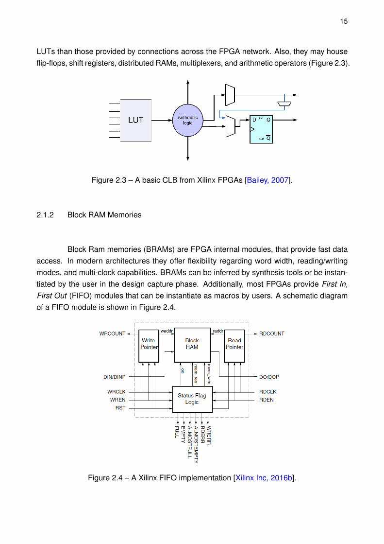
LUTs than those provided by connections across the FPGA network. Also, they may houseflip-flops, shift registers, distributed RAMs, multiplexers, and arithmetic operators (Figure 2.3).
Figure 2.3 – A basic CLB from Xilinx FPGAs [Bailey, 2007].
2.1.2 Block RAM Memories
Block Ram memories (BRAMs) are FPGA internal modules, that provide fast dataaccess. In modern architectures they offer flexibility regarding word width, reading/writingmodes, and multi-clock capabilities. BRAMs can be inferred by synthesis tools or be instan-tiated by the user in the design capture phase. Additionally, most FPGAs provide First In,First Out (FIFO) modules that can be instantiate as macros by users. A schematic diagramof a FIFO module is shown in Figure 2.4.
Figure 2.4 – A Xilinx FIFO implementation [Xilinx Inc, 2016b].
16
An important BRAM feature explored in this work is the double port access, i.e., it ispossible to have two memory accesses simultaneously. This feature enables data prefetch-ing or simultaneous read and write accesses.
2.1.3 DSP Blocks
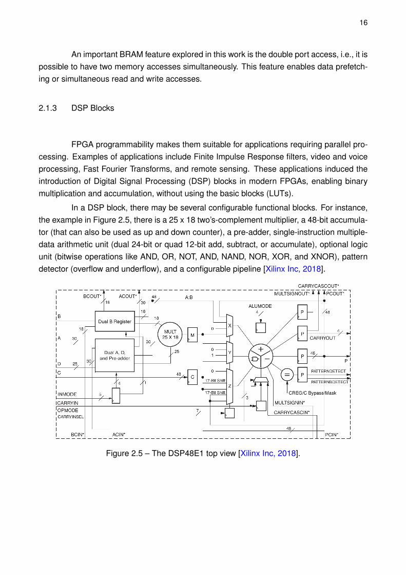
FPGA programmability makes them suitable for applications requiring parallel pro-cessing. Examples of applications include Finite Impulse Response filters, video and voiceprocessing, Fast Fourier Transforms, and remote sensing. These applications induced theintroduction of Digital Signal Processing (DSP) blocks in modern FPGAs, enabling binarymultiplication and accumulation, without using the basic blocks (LUTs).
In a DSP block, there may be several configurable functional blocks. For instance,the example in Figure 2.5, there is a 25 x 18 two’s-complement multiplier, a 48-bit accumula-tor (that can also be used as up and down counter), a pre-adder, single-instruction multiple-data arithmetic unit (dual 24-bit or quad 12-bit add, subtract, or accumulate), optional logicunit (bitwise operations like AND, OR, NOT, AND, NAND, NOR, XOR, and XNOR), patterndetector (overflow and underflow), and a configurable pipeline [Xilinx Inc, 2018].
Figure 2.5 – The DSP48E1 top view [Xilinx Inc, 2018].
17
2.1.4 The Virtex 7 FPGA
This work adopts the XC7VX690T Virtex 7 FPGA Xilinx device. The adoption ofthis device is due to its availability in the laboratory and a large number of internal resourcesfor prototyping [Xilinx Inc, 2016c]. Table 2.1 details some of this device available resources.
These resources correspond to the area restriction the work must follow. For eachlayer of the CNN, it is evaluated the number of required resources in such a way to makepossible to prototype the design in the target device.
2.2 Machine Learning
Machine learning is an area in Artificial Intelligence (AI) responsible for algorithmsthat can perform a task with no explicit programming to do so. The principle is to enablecomputers to learn from experience to solve problems that would be otherwise difficult (orimpossible) to be formally described by people.
A learning algorithm is an algorithm that is capable of learning from data. Formally,Mitchell [Mitchell, 1997] states that "A computer program is said to learn from experience (E)with respect to some class of tasks (T ) and performance measure (P), if its performance attasks in T , as measured by P, improves with experience E" . A task T may be a descriptionof how the algorithm should treat an input example, for instance, the problem of image clas-sification (described in subsection 2.2.1), is a machine learning task. The experience E isthe set of examples fed to the algorithm (a set of images in an image classification problem),while P is some form of quantitative performance measurement. It can be accuracy, errorrate, or any other measure that is function of the application.
2.2.1 Image Classification
One of the core problems in Computer Vision is the task of classifying an image. Itconsists in assigning an image into a class label from a fixed set of classes. The problemhas application in areas ranging from medical [Qing Li et al., 2014], defense [Yoshihisa Haraet al., 1994] and volcanology [Gabor Kereszturi et al., 2018].
18
Usually, a classification algorithm is split into two phases. The first phase is training.This phase is responsible for learning the model set of parameters, enabling the model tomap a certain input x to a class label k. Formally, a set of inputs in Rn (a tensor, suchas images) is used to induce parameter values so that a model f, which relates the inputexamples to the set of k classes. Thus, f : Rn → {1, ..., k}. Once training is complete, themodel is put to infer any new, to the set of the known classes, example x. In other words,the model is ready to classify new inputs.
2.2.2 Deep Learning
Similar to what happens in any area of Computer Science, part of the performanceof algorithms rely on how the input data is organized. In machine learning it is not different,the way the information is represented is paramount. Each piece of information consumedby a learning algorithm is called feature. Many tasks rely on hand-picked features to execute.Hence, prior to the execution of a learning algorithm, a set of features is extracted from thedata and supplied to the algorithm.
The approach of handcrafted features may work for some simpler tasks. However,the search for features can be difficult, or even impossible, depending on the problem com-plexity. Suppose an image classification algorithm. In order to classify a single class, a cat,for example, it should be known all the features that make an image of a cat different fromany other image. It would be possible to use as features the size and color of eyes, the fur,the tail, and so on. Nevertheless, each feature can appear in numerous variations of relativesize, orientation, angle, light, etc. Hence, it is impractical to code every feature of every classin problems of this size.
Deep learning models solve this problem by representing features internally. Thosemodels may describe a cat in terms of curves, shapes, and corners. According to Goodfellowet al., it extracts complex concepts in a hierarchical manner from less complex, raw data[Ian Goodfellow and Courville, 2016]. Moreover, in their words:
Machine learning is the only viable approach to building AI systems that canoperate in complicated, real-world environments. Deep learning is a particularkind of machine learning that achieves great power and flexibility by learning torepresent the world as a nested hierarchy of concepts, with each concept definedin relation to simpler concepts, and more abstract representations computed interms of less abstract ones.
19
2.2.3 Artificial Neural Networks
Artificial Neural Networks (ANNs) are a subset of deep learning models. ANNsprovide a general model that can learn its parameters from data in a process robust toerrors in the input data [Mitchell, 1997]. Besides the original inspiration on the biologicalbrain, modern ANNs do not attempt to imitate the biological brain in every aspect. Thehuman brain has approximately 1011 neurons, each connected on average to 104 others[Mitchell, 1997]. This enormously dense network in our brain gives more processing powerthan any computer ever built.
The fundamental unit in an ANN is the neuron (2.6). As described in [Haykin andHaykin, 2009], the neuron model is composed of three basic elements: (i) a set of synapses,where each synapse j, multiplied by a particular weight wkj , is connected to a neuron k ; (ii)an adder to sum up all the synaptic input values (and an additional bias); (iii) an activationfunction that limits the value produced by the adder.
Figure 2.6 – The neuron model [Haykin and Haykin, 2009].
Neurons can be connected in a variety of ways (or architectures). The most com-mon architectures are feedforward. For a network that is said to be feedforward, the dataflows strictly in one direction, from input to output. It can also have one or multiple layers;they distinguish in the presence of hidden layers. A hidden layer is any layer between thefirst input layer of neurons and last output layer. An example of such network is shown in2.7.
Despite the historical importance of Rosenblatt’s model, the fact that the classesclassified by the Perceptron needed to be linearly separable posed a limitation in applicabilityto the model. To solve this problem, the Multilayer Perceptron Network (MLP) was proposed.The MLP is a multilayer feedforward network, which means that it includes one or morehidden layers.
Haykin refers to three main characteristics of MLPs [Haykin and Haykin, 2009]:(i) the nonlinearity and differentiability of the activation functions presented on the neuron
20
Figure 2.7 – A fully-connected Artificial Neural Network.
model; (ii) the hidden layers; (iii) the high degree of connectivity. Those characteristics givethe model a great deal of generalization and performance for tasks like classification butmake the learning (or training) process challenging.
The most popular choice for training such networks is the backpropagation algo-rithm. In general terms, it occurs in two phases. The forward phase when the input datais provided to the input layer, and the data flow layer by layer through the network up tothe final, output, layer. The backward phase, calculates the error by comparing the resultproduced by the first phase with the expected output. Then, the error propagates throughthe network, layer by layer, in the opposite direction of the first phase. During the passagethrough the layers, the weights are adjusted accordingly to the error of each specific layer.As the focus of this work is on the first phase, also called inference, aspects related to thetraining of ANNs are out-of-the-scope of this work.
2.2.4 Convolutional Neural Networks
The idea of an artificial neural network aimed for visual pattern recognition camein 1983 by Fukushima, Miyake, and Takayukiito [Kunihiko Fukushima and Ito, 1983]. On thearticle entitled "Neocognitron: A neural network model for a mechanism of visual patternrecognition" the authors were the first to introduce the architecture that became known asConvolutional Neural Network (CNN). Their architecture was capable of classifying digitsfrom handwritten numerals. Later, in 1998, Lecun et al. were able to train a network of con-volutional neurons (Neocognitron) using the backpropagation algorithm [Yann LeCun et al.,
21
1989]. Since then, CNNs have grown in depth and size. Nowadays, it is possible to findnetworks with hundreds of layers [He et al., 2016]. Fortunately, the building blocks (convolu-tional and fully-connected layers) remain the same. Here, only the layers concerning Alexnetwill be detailed. However, most of them are still used in modern networks.
A convolution layer can be understood as a fully-connected layer which employsthe mathematical operation of convolution instead of the usual matrix multiplication. Lecunand Bengio pointed out the three main ideas that explain why convolutions are exceptionalin dealing with translated and locally distorted inputs (such as images): (i) local receptivefields; (ii) shared weights; (iii) and, optional subsampling [LeCun and Bengio, 1998].
The use of local receptive fields means that a convolutional neuron takes its inputfrom a reduced local of the input instead of the whole input as in a regular ANN. It alsomeans that the filter (or set of weights) belonging to a set of neurons is trained to extractfeatures that can appear in any location in the input. Additionally, it saves memory spaceonce the same set of weights is shared across the input. There is, also, the subsamplingthat reduces dimensionality to higher layers. The process of subsampling comes from theidea of complex cells feeding information to simpler cells in the visual cortex as described in[Kunihiko Fukushima and Ito, 1983].
The process in a CNN convolutional layer can be described as follows: it acceptsan Input Feature Map tensor (each map may also be called channel) and another tensorof filters [Sze et al., 2017]. Then, each filter window is convolved with (and slid across) itsrespective input channel forming a new set of feature maps. Next, a vector of bias can beadded to the feature maps, generating the final Output Feature Map tensor. The processcan be more readily understood by looking at Figure 2.8.
Formally, Equations 2.1 and 2.2 describe the convolution and fully-connected lay-ers, respectively.
O[c][x ][y ] = B[c] +C−1∑k=0
Width−1∑i=0
Height−1∑j=0
(I[k ][Sx + i ][Sy + j ] ∗W[c][i ][j ]) (2.1)
where: c, x and y are the current output channel, the horizontal and the vertical positionrespectively; also, C is the total number of input and filter channels, Width and Height cor-responds to the filter size; S is the stride1, and O is the output, I the input, and W the filtertensors and B the bias vector.
O[y ] = B[y ] +C−1∑k=0
Width−1∑i=0
Height−1∑j=0
(I[k ][i ][j ] ∗W[k ][i ][j ]) (2.2)
1The value of stride gives the number of positions that the filter slides over to the next window.
22
C
Input tensorFilter tensor Output tensor
C
Outpu
t ch
anne
ls
# fi
lter
s =
Out
put c
hann
els
Input WidthIn
put H
eigh
t
Filter Width
Fil
ter
Hei
ght
Output Width
Out
put
Hei
ght
# Biases = Output channels
Bias vector
Figure 2.8 – The convolution operation in CNNs.
where: O is the output vector plus I and W which are the input and weight tensors, as Bis the bias vector. The index y gives the current output neuron, C is the number of inputchannels, while Width and Height are the input width and height respectively.
Among convolutional and fully-connected layers, there can be other layers, such aspooling, activation, and normalization.
Pooling layers are applied to reduce dimensionality and avoid overfitting [Krizhevskyet al., 2012]. Typically, pooling is applied to each channel separately. The most two com-mon forms of pooling are mean and max-pooling, the latter is used by Alexnet. A max-poolconsists in a window of reduced size that passes over the input channel, in an overlappingfashion in the case of Alexnet, returning the maximum value. Besides, this value is writtento the output channel. More precisely, Alexnet uses windows of size 3 x 3 spaced by twopositions each in all of its pooling layers. There are three pooling layers in the Alexnet; theyfollow the convolutional layers number one, two and five.
Activation is an important operation that is, in fact, part of the neuron model. Ac-tivation functions add non-linearity to the network. There exist several functions that can beused: sigmoid, hyperbolic, exponential and Rectified Linear Unit (ReLU) are some of thefunctions found in the literature. Alexnet uses the ReLU activation function [Nair and Hinton,2010]. ReLU differs from other functions mainly because of its non-saturating (to valuesgreater tha zero) characteristic that makes the network training possible [Krizhevsky et al.,2012]. Equation 2.3 presents an example of the ReLU activation function.
23
ReLU(x) = max(x , 0) (2.3)
where: x is the value of each element in an Output Feature Map.
Normalization layers are applied (usually following activation layers) to control thedistribution in feature map values and, hence, they help to speed up learning and increaseaccuracy [Krizhevsky et al., 2012]. The normalization used across Alexnet layers is the LocalResponse Normalization (LRN). The authors in Alexnet explain that LRN aids the learningby increasing generalization, reducing top-1 and top-52 errors rates by 1.4% and 1.2% re-spectively [Krizhevsky et al., 2012]. Krizhevsky et al. introduced LRN as in expression 2.4.
bjx ,y =
aix ,y
(k + α ∗∑min(N−1,i+ n
2 )j=max(0,i− n
2 ) (ajx ,y )2)β
(2.4)
where: aix ,y denotes the activated neuron output of filter i at position (x, y) and bj
x ,y the nor-malized output at the same position. The idea is that a neuron gets its value by “averaging”over the N neighboring neurons. The other variables k, α, and β are hyper-parameters setby the network designer.
Nonetheless, the LRN normalization has not been used in most modern deep learn-ing architectures. It is observed the adoption of other normalization functions instead of theLRN, such as the Batch Normalization [Ioffe and Szegedy, 2015]. During the development ofthis work, it was decided that the hardware implementation of an LRN layer would not be car-ried on. Also, the LRN layer was omitted from software simulations to enable a compatibleverification against the hardware version.
The last operation, padding, is not a layer, but it is used in most networks. Thisoperation is useful to match the input size that feeds a layer with specific configurations. Inconvolutional layers, for example, sometimes it is desirable to use a particular stride and filtersize that will not match the input feature map dimensions. Hence, padding shall be applied.In the case of Alexnet, it uses zero-padding. It consists in adding rows and columns of zerosaround the original input map, creating a new map whose dimensions are acceptable by thenext layer (map size matches stride and filter size).
2.2.5 CNN Architectures
The literature is rich in CNNs solving problems in several areas. However, it ispossible to trace a historical trend of the development of CNN architectures by presentingthe first trainable CNN, LeNet, and the CNNs that recently scored best in the Imagenet
2In image classification applications, it is common to use the terminology of top-1 and 5. Top-N takes intoaccount the N classes that scored the highest probabilities among all classes in the output vector.
24
contest. This Section does not aim to present the architectures in full detail but introducesgeneral concepts related to the state-of-the-art in CNNs.
The first work to employ a trainable Convolutional Neural Network was LeNet[Yann LeCun et al., 1989]. In 1998, the architecture proposed by LeCun et al. was a seven-layers deep architecture that was able to recognize hand-written digits using 60 thousandparameters.
Later, in 2012, the Alexnet won the Imagenet contest [Krizhevsky et al., 2012]. Thearchitecture is deeper and has more parameters than LeNet. The Alexnet consists of fiveconvolutional layers of 11x11, 5x5, and 3x3 filters. With its 60 million parameters, Alexnetachieved a Top-5 error rate of 15.3% in the Imagenet dataset. The next year, the ZFNetwon the same contest [Zeiler and Fergus, 2014]. The architecture leveraged the Alexnetarchitecture, and by tuning of hyper-parameters, the ZFNet achieved a Top-5 error rate of14.8%.
Then, in 2014, GoogLeNet [Szegedy et al., 2015] achieved the surprisingly 6.67%Top-5 error rate. It was close to a human-level performance in image classification. TheGoogLeNet reduced, by using small filters, the number of parameters from the 60 million inAlexnet to 4 million. However, it introduced new elements such as the Inception module andan architecture of 22 layers deep. Also in 2014, the VGGNet attained 7.3% Top-5 error ratein the Imagenet dataset [Simonyan and Zisserman, 2014b]. Its architecture is more regularthat GoogLeNet, however, its 16 layers use 138 million parameters.
At last, in 2015 a CNN called ResNet beat human-level performance at the dataset[He et al., 2016]. The ResNet achieved 3.57% Top-5 error rate. The architecture is com-posed of 152 layers, with 60.2 million parameters. Also, it makes use of batch normalizationand other new techniques.
Among all cited CNNs, the architecture chosen to be implemented in this work isthe Alexnet [Krizhevsky et al., 2012]. There are two main reasons for this choice. First, thenetwork is a state-of-the-art large-scale CNN [Li et al., 2016]. Alexnet enables to exercise allthe crucial operations of any modern CNN such as multiple layers of cascaded convolutions,fully connected layers, activation, and max-pooling layers. Second, the Alexnet is a popularchoice of network to many authors who are working on dedicated hardware architectures,which makes it possible to run a future comparison against other implementations.
25
3. ALEXNET
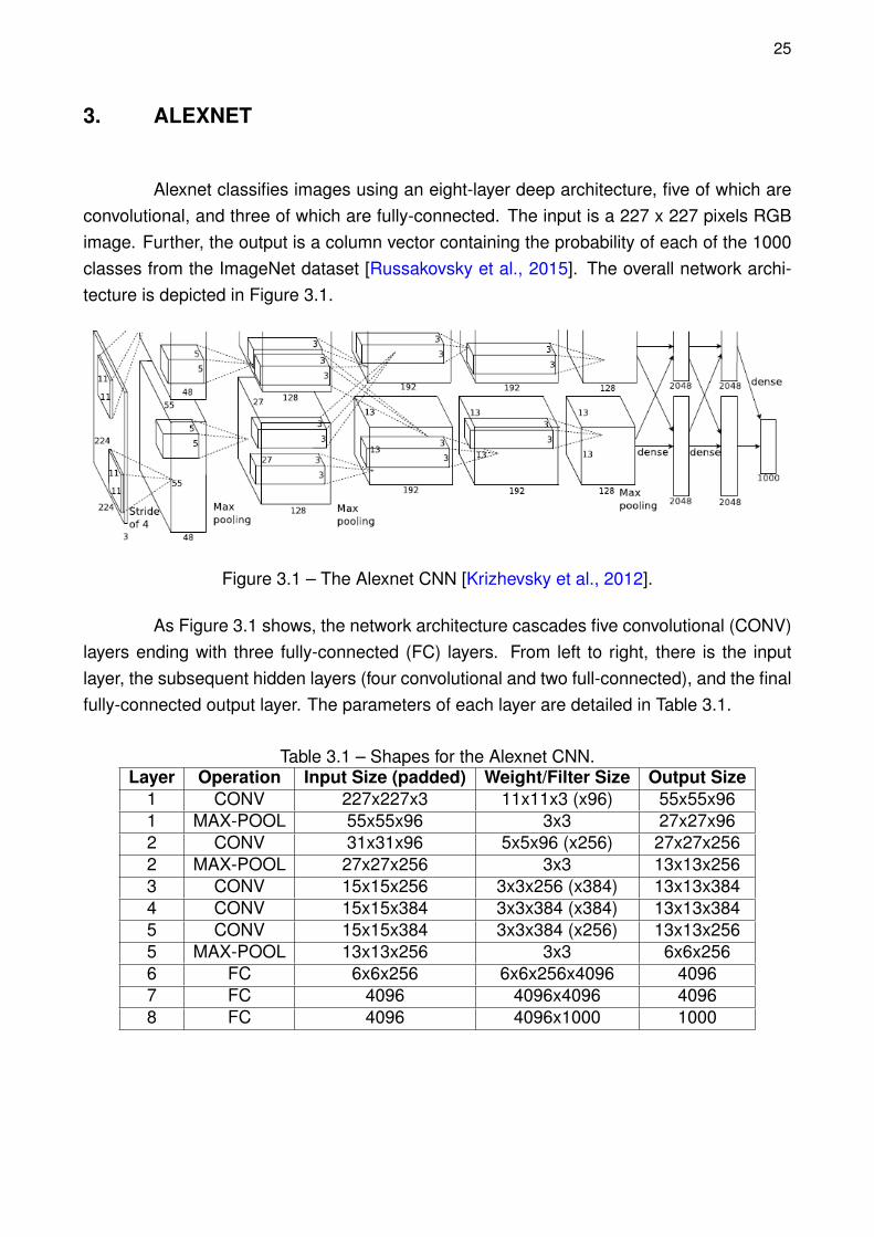
Alexnet classifies images using an eight-layer deep architecture, five of which areconvolutional, and three of which are fully-connected. The input is a 227 x 227 pixels RGBimage. Further, the output is a column vector containing the probability of each of the 1000classes from the ImageNet dataset [Russakovsky et al., 2015]. The overall network archi-tecture is depicted in Figure 3.1.
Figure 3.1 – The Alexnet CNN [Krizhevsky et al., 2012].
As Figure 3.1 shows, the network architecture cascades five convolutional (CONV)layers ending with three fully-connected (FC) layers. From left to right, there is the inputlayer, the subsequent hidden layers (four convolutional and two full-connected), and the finalfully-connected output layer. The parameters of each layer are detailed in Table 3.1.
Table 3.1 – Shapes for the Alexnet CNN.Layer Operation Input Size (padded) Weight/Filter Size Output Size
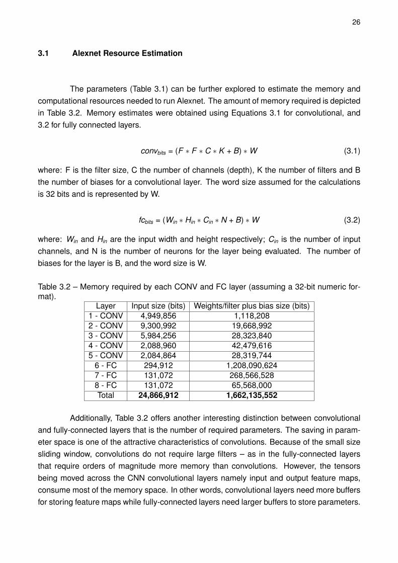
The parameters (Table 3.1) can be further explored to estimate the memory andcomputational resources needed to run Alexnet. The amount of memory required is depictedin Table 3.2. Memory estimates were obtained using Equations 3.1 for convolutional, and3.2 for fully connected layers.
convbits = (F ∗ F ∗ C ∗ K + B) ∗W (3.1)
where: F is the filter size, C the number of channels (depth), K the number of filters and Bthe number of biases for a convolutional layer. The word size assumed for the calculationsis 32 bits and is represented by W.
fcbits = (Win ∗ Hin ∗ Cin ∗ N + B) ∗W (3.2)
where: Win and Hin are the input width and height respectively; Cin is the number of inputchannels, and N is the number of neurons for the layer being evaluated. The number ofbiases for the layer is B, and the word size is W.
Table 3.2 – Memory required by each CONV and FC layer (assuming a 32-bit numeric for-mat).
6 - FC 294,912 1,208,090,6247 - FC 131,072 268,566,5288 - FC 131,072 65,568,000Total 24,866,912 1,662,135,552
Additionally, Table 3.2 offers another interesting distinction between convolutionaland fully-connected layers that is the number of required parameters. The saving in param-eter space is one of the attractive characteristics of convolutions. Because of the small sizesliding window, convolutions do not require large filters – as in the fully-connected layersthat require orders of magnitude more memory than convolutions. However, the tensorsbeing moved across the CNN convolutional layers namely input and output feature maps,consume most of the memory space. In other words, convolutional layers need more buffersfor storing feature maps while fully-connected layers need larger buffers to store parameters.
27
Similarly, it is possible to estimate the number of multiply operations for convolu-tional and fully-connected layers by the summations in Equations 2.1 and 2.2. For the sakeof brevity, only the number multiplications at each layer are shown here (Equation 3.3).
where: convmults denotes the total number of multiply operations in a convolutional layer,where F is the filter size, Cin the input channels, Cout the output channels, and Hout and Wout
are the height and width of the layer output.
On the other hand, for a fully-connected layer, the number of multiplications is givenby Equation 3.4
fcmults = (Cin ∗ Hin ∗Win) ∗ N (3.4)
where: Hin, Win, and Cin denote the input feature map size (height, width, and depth), and Nis the the number of neurons in the layer.
From Equations 3.3 and 3.4, Table 3.3 presents the number of multiply operationsfor each layer in the Alexnet. It demonstrates the computationally-intensive aspect of a mod-ern CNN. With the Alexnet example, another interesting point can also be made about thetwo types of layer. When analyzing the number of multiply operations required by each layer,it is clear that convolutional layers tend to demand more computation than fully-connectedlayers.
Table 3.3 – Alexnet total number of multiply operations.Layer Multiply Ops
6 - FC 37,748,7367 - FC 8,388,6088 - FC 2,048,000Total = 1,124,819,488
3.2 Software Evaluation
The first step towards a more significant understanding of the particularities in theimplementation of CNNs was to execute and evaluate a publicly distributed version of Alexnetin software. The second step was to implement a simpler version in C language where it
28
would be possible to get familiar with the data structures involved in a CNN forward execu-tion.
3.2.1 Public Software Distribution
Besides the recent improvements in the available hardware as seen in the formof new GPU, ASIC, or FPGA platforms [Nvidia, 2018, Jouppi et al., 2017, Ovtcharov et al.,2015], the observed increase in software frameworks has also influenced the development ofnew deep learning networks. There is a multitude of publicly available, open-source, frame-works tailored to the development of artificial neural networks. They facilitate the portabilityof models across developers and add the transparency necessary to experiment with differ-ent hardware platforms [Sze et al., 2017].
For example, The Caffe framework was made public in 2014 by the University ofCalifornia, Berkeley [Jia et al., 2014]. In 2015, Google launched the Tensorflow frameworkwhere it is possible for the developer to smoothly run the CNN either in GPUs or conven-tional CPU architectures just by editing a few lines of its Python script [Abadi et al., 2016].Facebook also has its open-source framework, called Torch [Collobert et al., 2002]. Despiteall the cited frameworks being capable of running the Alexnet, a portable framework with noparticular library dependencies was needed to enable simulation on an embedded environ-ment. Consequently, the Tiny-Dnn library was used to evaluate the Alexnet in an embeddedenvironment [Nomi, 2018].
The simulation was carried out on the Open Virtual Platform (OVP) [Imperas, 2018].OVP provides a platform for embedded systems development, supplying models for a varietyof processors such as PowerPC, RISC-V, MIPS, and ARM. Next, it was possible to cross-compile the Alexnet C++ implementation, provided along with the Tiny-Dnn, targeting theARMv8 instruction set. Thus, the executable file can be loaded and run over the simulatedARM Cortex-A57 single core processor. Additionally, the simulated system was required toembed the Linux kernel (version 4.3.0). The operating system was necessary to providesome basic system calls as the Tiny-Dnn network implementation is not “bare-metal.”
The first evaluation regards the number of ARM ISA instructions used during clas-sification of a single image on the Alexnet. To do so, it was essential to separate the in-structions executed during the Linux system boot from the instructions that were employedduring classification. The applied method consists in running several executions of two differ-ent Linux initialization scripts. The first one simply waited for the system to boot and halted.The second script, however, performed a classification after the boot is completed and thenhalted the system.
Further, after several executions of both scripts, the average number of instructionscan be calculated for booting the system and for booting plus a single Alexnet execution. The
29
difference in the number of instructions gives the average instructions count for classifyingan image on the Alexnet Convolutional Neural Network. Table 3.4 presents the instructioncount for five executions of both scripts. The simulation was executed multiple times withthe same input because it was not possible, to the author knowledge, to stop the instructioncounting precisely after the halting of the operating system.
Table 3.4 – Average instruction count (∗109) by single image classification, obtained fromOVP reports.
Execution Linux boot plus Alexnet Only Linux boot1 739.4 430.52 802.4 510.53 655.5 437.04 743.6 538.05 746.3 445.2
AVG = 737.5 472.2Average instructions by classification: 265.2
After evaluating the total number of instructions, the Alexnet execution time wasmeasured using the Linux command time. The result is given in Table 3.5.
Table 3.5 – Time for the classification of a single image with the Tiny-Dnn library, measuredfrom the OVP simulation.
Alexnet execution time (in seconds)real user sys
34.24 32.57 1.67
The second evaluation proposed for the Tiny-Dnn Alexnet implementation is mem-ory consumption. Here, the Valgrind tool was used to perform a memory consumption eval-uation [Nethercote and Seward, 2007]. The analysis was performed on the host machine,once the simulated environment does not provide all the necessary Linux packages for theValgrind installation. Regardless, the same source code was profiled which gives roughlythe same number of memory allocations. In Figure 3.2, the memory heap consumption isportrayed. The peak memory usage reaches over 520 MB.
3.2.2 Implemented Software
Next, the CNN was implemented in the C language. First, this was mainly motivatedby the initial modeling of the problem. Second, to facilitate the latter hardware verification(providing verification "checkpoints" in the CNN data flow). Lastly, the software written in Ccan be compiled to run in bare-metal platforms enabling more accurate statistics from theOVP simulator that serve as a reference in performance for the hardware. Appendix A showsthe code for the Alexnet CNN written in C.
30
Figure 3.2 – Memory heap consumption for the C++ Alexnet inference.
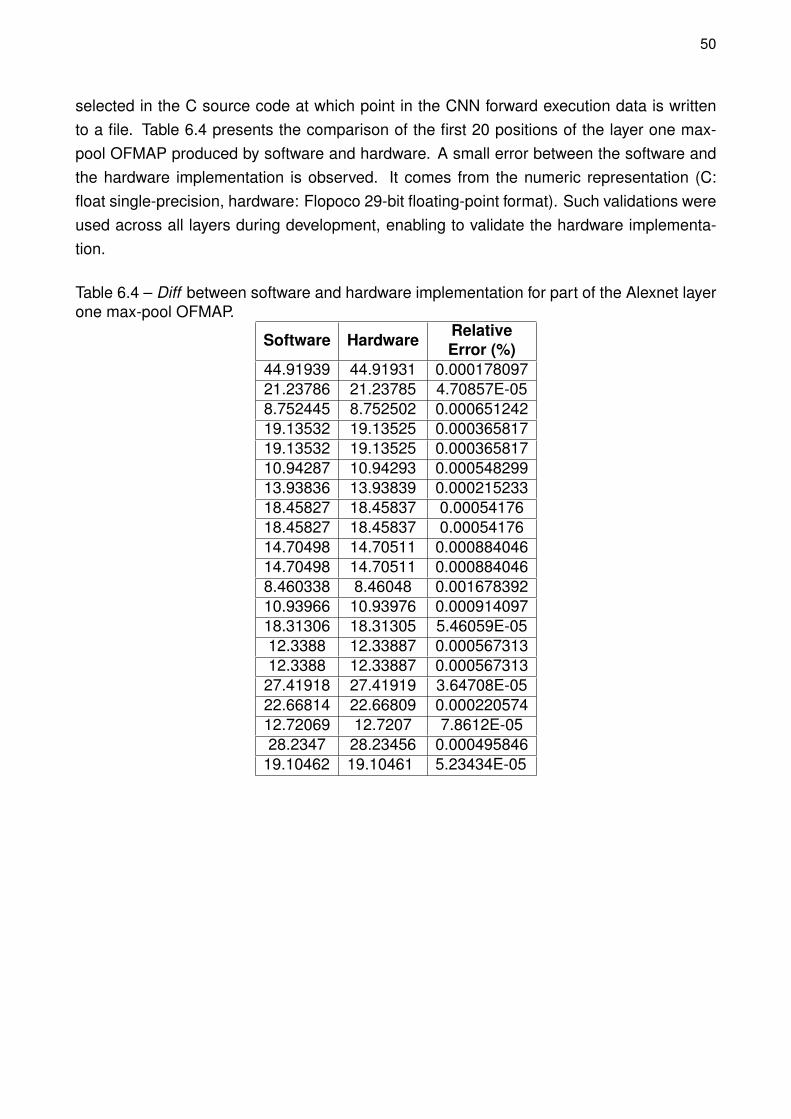
The implemented software was validated using the Tiny-Dnn distributed version.To perform the validation, the output vector of both implementations were compared afterthe classification of 11 different images. After the executions, the same Top-5 classes wereretrieved by the two output vectors on all images. However, when comparing the outputvectors from the last fully-connected layer, a small error was found (Table 3.6) which can beexplained by differences in the code of arithmetic functions provided by C++ libraries, usedby Tiny-Dnn, and the software written in C. The error was measured as the element-wiseabsolute difference, the maximum difference found after the classification of 11 images ispresented in the Table.
Table 3.6 – The absolute maximum error between implemented and distributed software.Image Max Absolute Error
slippers 0,001310173Avg Max Absolute Error: 0,001231936
31
Simulated on the ARM Cortex-A5, the bare-metal Alexnet classified an image exe-cuting 116.1x10⁹ ARMv7 ISA instructions (OVP report). Moreover, the total simulated timewas 1,161.13 seconds and the memory usage peak, profiled by the Valgrind tool, achieved250.5 MB (Figure 3.3). Note that using a simpler embedded processor (ARM Cortex-A5)than ARM Cortex-A57 the number of instructions reduced by 50% because there is nosystem calls neither the complexity of object-oriented structures. On the other side, theexecution time increases 37 times.
Figure 3.3 – Memory heap consumption for the C Alexnet inference.
Executing the software on the host machine, an Intel Core i7 at 3.4GHz with 8Gbytes of memory, the classification took only 3.234 seconds. The result is impressive, andfuture works aim to explain the optimizations made by the compiler and the architecture toexecute all arithmetic and memory accesses required during an image classification.
32
Concluding, the implemented software was validated using the Tiny-Dnn (C++)framework and simulated on a virtual ARM platform. Also, it offers means for performing anincremental verification of the hardware by producing a set of files that contain the valuesof specific points in the architecture. Additionally, it makes possible to use the simulatedenvironment as a baseline for performance analysis.
33
4. HARDWARE INFRASTRUCTURE
This Chapter presents the modules used in the hardware implementation. Also, itdetails the memory architecture, the floating-point format, and the arithmetic operators.
4.1 Generic Memory Module
One of the main goals behind this project is to make the hardware modules asgeneric as possible. It enables, via off-line configuration, the design to implement a CNNwith any set of parameters and size.
The first issue addressing the generality of the design is the memory. Throughoutthe design, the same memory module is instantiated for both input and output feature mapsand weight values. Hence, the first configuration parameter of this memory is depth, whichallows configuring the amount of BRAMs for each instance. Another parameter is width.This second parameter is important so the memory will not pose a problem for changes innumeric format. In other words, it is possible to tweak the numeric precision with no need torewrite memory modules.
Specifically, the memory is configured with B blocks and each block has W BRAMS(of 1 bit width each), where W is the word-length. Figure 4.1 gives the schematic of a genericmemory instance configured with 3 blocks and 29-bit word (width of the floating-point numberused in this work and described in the next Section). Besides, the total BRAM size beingequal to 36 Kb, the effective data storage is 32 Kb since for every 8 bits there is a parity bit.In Figure 4.1, the total number of addressable 29-bit words is 96,000. This Figure shows theschematics for the memory module implemented for this work. The module called GenMemis configurable in depth to store the set of weights and feature maps that vary in size acrosslayers.
Any convolutional layer works with at least three data structures: filter, input, andoutput feature map. For instance, the Alexnet layer one input is a 227x227x3 tensor (Table3.1), which corresponds to 154,587 29-bit floating-point words. Dividing it by 32Kb, thiscorresponds to 5 blocks (B), or 145 BRAMs. To store the output feature map produced bythe max-pool in layer one, according to Table 3.1, 69,984 words are required, resulting in 3blocks, or 87 BRAMs. Finally, the layer one filter and bias take 34,944 words, resulting in 2blocks, or 58 BRAMs. Thus, for the input, output, and filter, 10 blocks of generic memoryare used in layer one. This represents 290 BRAMs, corresponding to 20% of the availableresources in the target FPGA.
34
36K
bB
RA
M #
283
6Kb
BR
AM
#28
36K
bB
RA
M #
28
Line Address A
Line Address B(14 downto 0)
36K
bB
RA
M #
2
36K
bB
RA
M #
1
36K
bB
RA
M #
0
36K
bB
RA
M #
2
36K
bB
RA
M #
1
36K
bB
RA
M #
036
Kb
BR
AM
#0
36K
bB
RA
M #
1
36K
bB
RA
M #
2
Port A input
29
Port B input
29
1 1 1 11 1 1 1
AddrB AddrB AddrB AddrB
AddrBAddrBAddrBAddrB
AddrB AddrB AddrB AddrB
AddrA AddrA AddrA AddrA
AddrAAddrAAddrAAddrA
AddrA AddrA AddrA AddrA
InA
InB
InA
InB
InA
InB
InA
InB
InA
InB
InA
InB
InA
InB
InA
InB
InA
InB
InA
InB
InA
InB
InA
InB
Address B
15 + log(# of Blocks)
(14 downto 0)
Address A
15 + log(# of Blocks)
(15+log(# of Blocks) downto 15)
Wen A
Wen
AW
enB
Wen
AW
enB
We
nAW
enB
Wen
AW
enB
Wen
AW
enB
We
nAW
enB
Wen
AW
enB
Wen
AW
enB
Wen
AW
enB
Wen
AW
enB
We
nAW
enB
Wen
AW
enB
(15+log(# of Blocks) downto 15)
Wen B
Out
AO
utB
Ou
tAO
utB
Out
AO
utB
Ou
tAO
utB
Ou
tAO
utB
Out
AO
utB
Ou
tAO
utB
Out
AO
utB
Out
AO
utB
Ou
tAO
utB
Out
AO
utB
Ou
tAO
utB
Port A output
29
Port B output
29
29
29
29
29
29
29
RenABTo all BRAMs.
Figure 4.1 – Schematic of the memory module (with a 3 blocks and 29-bit wide configura-tion).
4.2 Floating-Point Format
Despite existing studies pointing out that the use of fixed-point has a little impacton the performance of deep learning accelerators [Jiao et al., 2017, Courbariaux et al.,
35
2015, Gupta et al., 2015], this work adopted floating-point representation to minimize theaccumulated error between layers and to make it easy the verification against the softwareversion. Our work adopted the Flopoco framework for floating-point arithmetic [de Dinechinand Pasca, 2011]. The framework provides a list of configurable arithmetic operators tailoredfor FPGAs, along with its proper floating-point format.
The format used across all modules of this work is the Flopoco floating-point config-ured to an 8-bit exponent and 18-bit mantissa (Figure 4.2). The exponent width was chosenbased on the IEEE-754 standard that uses an exponent of same size [IEEE, 2008]. However,the mantissa was set to the DSP block input width of the target FPGA [Xilinx Inc, 2018]. Itwas necessary to fit the significand part to the DSP block input, so the integer multiplicationsrequire a single block to be performed.
MantissaExponentException
Sign
0171825262728
Figure 4.2 – The adopted floating-point format.
4.3 Arithmetic Operators
The Flopoco framework offers an extensive list of operators1. This section onlypresents the ones instantiated in this design.
4.3.1 Multiplier
Multiplication is at the core of convolutional and fully-connected layers. With theFlopoco floating-point multiplier at hand [de Dinechin and Pasca, 2011], it was necessaryto modify it, by instantiating the DSP Block. The DSP block, which executes the IntegerMultiplication (Figure 4.3), was manually inserted in the multiplier VHDL code from Flopoco.Afterwards, a control logic around the multiplier was implemented to control and synchronizethe operation with other modules (not depicted in Figure 4.3).
The resulting module is capable of multiplying two floating-point numbers in threeclock cycles. Also, it uses 205 LUTs, 166 flip-flops, and a single DSP block.
1http://flopoco.gforge.inria.fr/
36
Operand A
Operand B
Sign
Exponent
Mantissa
+ -
127(BIAS)
IntegerMultiplication(DSP Block)
+
SigProd
Sig
Pro
d(37
)
ExpSum
SigProd << 1 if SigProd(37) = '1'else SigProd << 2
SigProdExt
ExpPostNorm
Mantissa normalization
Exponent normalizationExponent addition
SigProdExt(37:20)
'0' if sigProdExt(18:0) is “00...00”else '1'
SigProdExt(18:0)
Guard bit
SigProdExt(19) = stick Stick AND (Guard AND !sigProdExt(19)) OR
sigProdExt(20)
Round bit
+
Guard
Ro
und
ResultRound Adder
2 + 8 + 18
2 + 8 + 182 + 8 + 18
8
8
18
18
38
18
28
Sign
Exponent
Mantissa
Result Sign
Figure 4.3 – Floating-point multiplier top view.
4.3.2 Adder
Another important operation in CNNs is addition. Most modern accelerators andhardware implementations adopt multiply and accumulate (MAC) modules [Sze et al., 2018,Sze et al., 2017, Venkataramani et al., 2017]. The obvious advantage on using MACs isprecision, because the accumulator comes right after the multiplication module, and theresult of the first operation is not rounded. However, in our case, multiplication and additioncould not be "glued" together due the the adopted architecture, which will be presented inthe next Chapter.
Conceptually, the floating-point addition takes more area and time than multipli-cation to execute. Flopoco implements both single and dual path floating-point adders[de Dinechin and Pasca, 2011]. Figure 4.4 shows the dual path floating-point adder avail-able in the Flopoco framework. According to Muller in [Muller et al., 2010], the dual patharchitecture is optimal for FPGA designs once it has little area overhead compared to othersingle path implementations and the shifter amortizes the delay in the leading-zero counting.In a dual path adder, first, the exponents are compared and the operands possibly swapped.Next, the operands may be shifted to align the mantissas and one of them complemented incase of subtraction. Then, based on the difference of the exponents, the result of the closeor far path is selected. The close path is chosen when the case is a subtraction of inputswith exponents that differ by at most one bit. One the other hand, the far path is chosen foradding or subtracting numbers with distant exponents (at least two bits).
The Flopoco dual path adder tailored to this work performs a floating-point additionin six clock cycles, taking 324 LUTs, 18 shift-registers (SRL) and 208 flip-flops.
37
Figure 4.4 – The dual path floating-point adder architecture [Muller et al., 2010].
4.3.3 Fixed-Point Converter
The last Flopoco operator used is a converter to fixed-point format. Conversionwas necessary to perform comparisons in the max-pool layer. The layer, explored in moredetail in the next Chapter, first converts all the input values to fixed-point, then finds themaximum value among them by comparing their fixed-point representation. Basically, theconversion consists of a shifter, by the amount in the exponent, and a possible truncation.The framework also offers conversion to fixed-point with rounding; however the additionalhardware was not seen as necessary to perform the max-pool layer.
The choice for the fixed-point size required attention to avoid overflow and under-flow. The fixed-point width was set to 32 bits, where the lower 15 bits are the fractional part,the next 16 bits represent the integer part, and the most significant bit gives the sign. Thissetting gives a range from -65536 (216) to 65535.9999695 (216 − 2−15), which is enough toperform comparison operations like greater than in the max-pool layer.
38
5. HARDWARE IMPLEMENTATION
Following a top-down approach, this Chapter presents the modules that composethe implemented architecture. First, a top view of the architecture is provided. The nextsections detail the modules responsible for performing the convolution and max-pool layers,accessing weight and feature map memories, as well as the multilayer module, which canexecute an unlimited number of convolutional layers sequentially. Concluding the Chapter, abrief discussion of the fully connected layers is offered since this layer was not implementeddue to the lack of time to design it.
Figure 5.1 presents the proposed architecture to implement each layer of the CNN.The left memory (A) contains the pre-processed input image and memory B contains theset of weights for the first layer. The first layer includes the convolutional and max-poolmodules that fill the output feature map memory (C). Next, the second layer reads memoryC, executing the functions related to the second layer. Once layer two is completed, theMultilayer starts. The multilayer executes sequentially layers three, four, and five. Note thatthis multilayer structure enables to implement an arbitrary number of layers sequentially. Theresult of the fifth layer is written into the output feature map, in memory G. This architectureis, in the Authors opinion, a relevant contribution, since it allows to implement CNNs with anarbitrary number of layers.
Mem
Gen
(A)
Inpu
t Im
age
Mem
Gen
(B)
Lay
er 1
wei
ghts
Layer1
Mem
Gen
(C
)O
utp
ut F
MA
PS
Mem
Gen
(D
)L
ayer
2 w
eigh
ts
Layer2
Mem
Gen
(E
)O
utpu
t F
MA
PS
Mem
Gen
(F
)La
yers
3 a
nd 5
wei
ghts
MultilayerM
emG
en (G
)O
utpu
t F
MA
PS
Mem
Gen
(I)
Laye
r 4
we
ight
s
Figure 5.1 – Architecture top view.
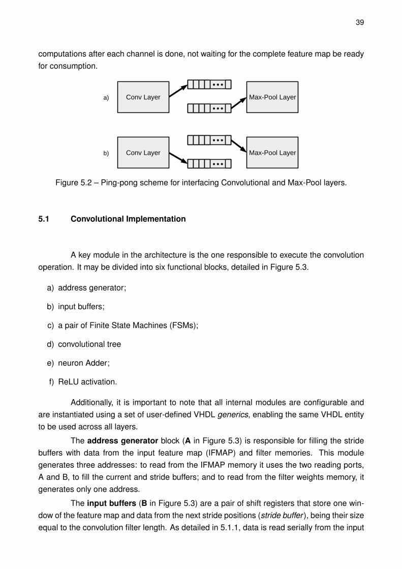
The "Layer" encapsulates the convolutional and max-pool modules, interconnectedin a "ping-pong" arrangement (Figure 5.2). While the producer (convolutional layer) writeson the upper buffer, the consumer (max-pool layer) reads from the lower buffer (a). In b,producer and consumer switch buffers and the consumer starts reading from the just filledbuffer, as the producer writes over the already consumed data in the lower buffer. The firstadvantage in using "ping-pong" buffers is memory saving, once it requires less memoryspace since only two channels need to be stored instead of the entire feature map. Forexample, the first layer channel size is 55x55 while the entire feature map contains 96 chan-nels. The second advantage is the latency reduction since the max-pool layer starts its
39
computations after each channel is done, not waiting for the complete feature map be readyfor consumption.
Conv Layer Max-Pool Layer
Conv Layer Max-Pool Layer
a)
b)
Figure 5.2 – Ping-pong scheme for interfacing Convolutional and Max-Pool layers.
5.1 Convolutional Implementation
A key module in the architecture is the one responsible to execute the convolutionoperation. It may be divided into six functional blocks, detailed in Figure 5.3.
a) address generator;
b) input buffers;
c) a pair of Finite State Machines (FSMs);
d) convolutional tree
e) neuron Adder;
f) ReLU activation.
Additionally, it is important to note that all internal modules are configurable andare instantiated using a set of user-defined VHDL generics, enabling the same VHDL entityto be used across all layers.
The address generator block (A in Figure 5.3) is responsible for filling the stridebuffers with data from the input feature map (IFMAP) and filter memories. This modulegenerates three addresses: to read from the IFMAP memory it uses the two reading ports,A and B, to fill the current and stride buffers; and to read from the filter weights memory, itgenerates only one address.
The input buffers (B in Figure 5.3) are a pair of shift registers that store one win-dow of the feature map and data from the next stride positions (stride buffer ), being their sizeequal to the convolution filter length. As detailed in 5.1.1, data is read serially from the input
40
Mem
Ge
nIn
put
ten
sor
AddrB
AddrA
InA
InB
Wen
Out
AO
utB
Me
mG
enW
eig
ht t
ens
or
AddrA
InA
Wen
Out
A
Current Buffer
Stride Buffer
Current Buffer
ConvolutionFSM
Address GeneratorProcess
Enable
Control Signals
StrideFSM
X X X X
+ +
+
X
ConvolutionTree
Control Signals
+Result
Mem
Gen
Out
put
chan
nel
AddrB
AddrA
InA
InB
Wen
OutA
Ou
tB
Bia
s A
rray
Bias Address
28 28 28 28
28282828
28
28
2828
28
28
28
28
28
28
15 + log(# of Weights MemBlocks)
15 + log(# of Input MemBlocks)
15 + log(# of Input MemBlocks)
15 + log(# of Output MemBlocks)
15 + log(# of Output MemBlocks)
ReLU Activation
Data In
Data In
Data In
Addr Out
Data Out
NeuronAdder
(A) (B)
(C)
(D)
(E)
(F)
Figure 5.3 – Convolutional layer schematic.
memories. There is also another buffer, responsible for storing the weights of the currentfilter.
A pair of FSMs (C in Figure 5.3) control the operation of the convolutional treeand manage the write and read timing between the input buffers and the address generator.The FSMs need to be tightly synchronized to produce the right set of output values. Thissynchronization is important because the number of clock cycles taken by the convolutionaltree, loading the current buffer, loading the stride buffer, and memory latency are different.In other words, the time spent by the convolution differs accordingly to the filter and stridesize.
The convolutional tree (D in Figure 5.3) computes a window of convolution. Atthe leaves, it multiplies the IFMAP with the weight array. Then, it adds the multiplicationresults in a tree of adders. This module is also portable to any filter size. Afterwards, theconvolutional tree produces a value, which is passed to the neuron adder. The neuronadder is in charge of summing up the results from the input channels belonging to the sameoutput neuron. Additionally, this final adder adds the bias. To put it differently, when the resultwindow of the first input channel is produced, there is no value to increment, so the bias isadded to it and the neuron adder output is written to the OFMAP memory. Then, during theconvolutions in the next channels, the result window is accumulated together with the valuealready stored in the OFMAP. This process avoids the extra step of the bias addition afterthe OFMAP completion.
Only when the next layer reads from the output feature map (OFMAP), the acti-vation (E in Figure 5.3) function is executed. The address generated by the next layer isread from the memory, then, it passes through the activation module that performs the ReLU
41
operation (F in Figure 5.3). In other words, it only outputs values greater than zero from theOFMAP memory.
5.1.1 Buffers Operation
This section details the input buffers – B in Figure 5.3. As explained in Sec-tion 2.2.4, the convolution slides a window (the filter) through the IFMAP. This window readsa certain number of positions to execute the computation of the next neuron. Normally, thewindow size is greater than the stride, which makes part of the current window useful to thenext convolutional window. This property was used to decrease the time spent in loadingvalues from the IFMAP in the convolutional module.
For instance, in the Alexnet first layer, the window size is 11x11 with a stride of 4.It means that 121 values need to be loaded from the IFMAP memory at first. For the nextwindow, the addresses increment four positions to the right. Thus, instead of reading all 121values, only 44 new values are read (4 * 11). For instance, consider the buffers configuredto a window size of 3x3 and stride of 2, as shown in Figure 5.4.
Serial Input
Stride Input
Out
0
Out
1
Out
2
Out
3
Out
4
Out
5
Out
6
Out
7
Out
8
Load Stride Current Buffer
Stride Buffer
In
In
In
29
29
29 29 29 29 29 29 29 29 29
Figure 5.4 – Current and stride buffers.
At the beginning of an operation (a new window or a new IFMAP), both buffers areempty. Then, the current buffer is loaded with a window according to the addresses gen-erated by the "address generator" block. After filling the current buffer, the FSM controllingthe convolutional tree starts the computation. During the time spent by the tree, the secondFSM (Stride FSM at Figure 5.3) switches the IFMAP memory port to the stride buffer andthe address generator starts to request the next two addresses for each line in the window.Then, the stride buffer is ready to be loaded into the current buffer, which is done when theConvolution FSM pulses the Load Stride signal. Finally, the current buffer has the contentsfor the next window, and a new convolution can be computed.
This process optimizes the loading from IFMAP by inserting cutoff paths in the shiftregisters. This is possible by using a memory port that is idle during the long arithmetical
42
operations. This process reduces the memory access by keeping some values and load-ing only the stride to the input buffer. In the case of the Alexnet layer one, this reductionrepresents 36.3% less memory reads in subsequent windows (44 instead of the 121 reads).
5.1.2 Convolutional Tree
Most of the literature in Deep Learning accelerators adopts systolic arrays to im-plement convolutions. Works [Chen et al., 2016] and [Jouppi et al., 2017] employ a set ofmultiply-accumulate (MAC) operators disposed in a grid-like structure. The approach hasthe advantage of a high level of parallelism. However, it requires a considerable amount ofresources. First, each node in the grid consists in a pair of multiplier and accumulator. Sec-ond, the grid requires a network to interconnect all MACs to pass the output values to otherneighboring MACs. Last, besides storing the feature maps and filters, there is the need fora large number of input buffers spread around the grid to input the feature maps and filters.
X X X X X X X X X
+ + + +
+ +
+
+
In 0
In 1
In 2
In 3
In 4
In 5
In 6
In 7
In 8
W 0
W 1
W 2
W 3
W 4
W 5
W 6
W 7
W 8
Result
Figure 5.5 – Example of a 3x3 multiply-add tree.
An architectural option to systolic arrays is the multiply-add trees – Figure 5.5 andD in Figure 5.3. This approach uses a line of multipliers and an adder tree [Zhang et al.,2015]. The inputs of the multiply-add tree are the current buffer and the weight array. Next,the result produced by each pair of multipliers are added in the next level. The result of theadders in the first level travels up the tree, until the root, which produces the final result. Themodule implemented in this work is capable of implementing convolutions of any size. Thesize of the adder tree is configured through VHDL generic parameters.
The multiply-add tree is pipelined. The multiplication takes 3 clock cycles and eachaddition 5 clock cycles. Thus, for layer one there are 121 multipliers in parallel (plus 7 dummy
43
modules to obtain a full binary tree), and 8 adder levels (log2n + 1). The time to computeone 11x11 convolution in the current implementation is 43 clock cycles.
5.2 Max-Pool Layer
Simpler than the Convolutional Layer, the Max-pool Layer makes use of a singleFSM that controls a shift register input buffer and the max-pool tree. A process generatesthe address of each window loading the input buffer. When the window is ready (buffer full),the FSM starts the max-pool tree. After the maximum value in the window is found, it iswritten to the OFMAP memory.
To illustrate a 3x3 max-pool tree, Figure 5.6 shows that the input values are con-verted to a fixed-point format (as presented in Section 4.3.3). Then, the tree of comparatorsevaluates all values. It is important to note that the fixed-point numbers are not re-convertedto floating-point. Instead, they only serve to perform the comparisons that will decode theoutput value. Hence, no precision is lost in the conversion from and to fixed-point, and thecomparator can be simplified to work with integer operands.
In 0
In 1
In 2
In 3
In 4
In 5
In 6
In 7
In 8
Start (en)
Flo
atin
g t
oF
ixe
d P
oin
t(F
ix 0
)
Flo
atin
g t
oF
ixe
d P
oin
t (F
ix 1
)
Flo
atin
g t
oF
ixe
d P
oin
t(F
ix 2
)
Flo
atin
g t
oF
ixe
d P
oin
t(F
ix 3
)
Flo
atin
g t
oF
ixe
d P
oin
t(F
ix 4
)
Flo
atin
g t
oF
ixe
d P
oin
t(F
ix 5
)
Flo
atin
g t
oF
ixe
d P
oin
t(F
ix 6
)
Flo
atin
g t
oF
ixe
d P
oin
t(F
ix 7
)
Flo
atin
g t
oF
ixe
d P
oin
t(F
ix 8
)
> > > >
> >
Fix 0,0
Fix 0
Fix 1
Fix 2
Fix 3
Fix 4
Fix 5
Fix 0,1 Fix 0,2 Fix 0,3
Fix 6
Fix 7
Res 0,0 Res 0,1 Res 0,2 Res 0,3
Fix 1,0 Fix 1,1
FIx
0,0
Fix
0,1
Fix
0,2
Fix
0,3
>
Res 1,0 Res 1,1
Fix 2,0
Fix
1,0
Fix
1,1
Res 2,0
>
Maximum Value28 28 28 28 28 28 28 28 28
32 32 32 3232 32 32 32 32
In 0
In 1
In 2
In 3
In 4
In 5
In 6
In 8
In 7
Res 3,0
Figure 5.6 – The max-pool tree.
44
5.3 Multilayer
Following the first two Alexnet layers, the Multilayer module implements the Alexnetlayers three, four, and five. As shown in the top view (Figure 5.1), the Multilayer feedbacksitself creating a loop that could implement any number of subsequent convolutional layers ofthe same filter size. Even that the Multilayer could be used to implement all five convolutionallayers on Alexnet, the architecture dedicates two Layer modules for the first two convolutionallayers, which have filter sizes of 11x11 and 5x5, while the remaining layers, executed by themultilayer, have filters of size 3x3. The hardware implementation as it is, depends on the off-line configuration to instantiate the convolutional tree. An improvement could be made to re-configure at run-time the convolutional tree, so it would be possible to execute convolutionsof different filter sizes. Another important aspect of the Multilayer module is that it savesFPGA resources since only one module is capable of performing multiple CNN layers.
The Multilayer encapsulates a convolutional module and the ping-pong buffer thatinterfaces with a max-pool or a module that, simply, writes the data from the ping-pongbuffer to the OFMAP (when no max-pool is performed such as in the Alexnet layers threeand four). Additionally, there is a control FSM that coordinates the two multiplexers seen intop view. To keep the diagrams in Figures 5.1 and 5.7 simplified, they do not display thecontrol connections from the FSM in the Multilayer. However, it is important to mention itsrole in the operation of the Multilayer module.
In the case of the Alexnet CNN, during the execution of layer two, the multiplexersare first controlled to pass the OFMAP from layer number two to the memory E (Figure 5.1).Next, when Multilayer starts to perform the computations of layer three, the FSM sets themultiplexers in a way that the Multilayer reads the IFMAP from memory E and writes theOFMAP to memory G. As soon as layer three is done, the FSM re-configure both multi-plexers, so the Multilayer starts to perform the convolutional layer four, reading the IFMAPfrom memory G and writing the resulting OFMAP to memory E. Finally, layer five can startits execution. The FSM, then, returns to the initial configuration, where the IFMAP comesfrom memory E as the OFMAP goes to memory G. Similarly, the FSM controls from whichmemory (F or I) the Multilayer reads the set of filter weights.
5.4 Fully-Connected Layer Exploration
Unfortunately, due to the limited time to develop this project, the fully-connectedlayers were not implemented. Some exploration was done to access the viability of embed-ding these layers into an FPGA. As demonstrated in Section 6, the convolutional layers areconsuming most of the available FPGA already. Hence, it is necessary to explore techniques
45
Conv Layer
Max-Pool Layer
Bypass
Mem
Ge
nO
FM
AP
Ping-pong buffer
Figure 5.7 – The Multilayer module.
to decrease the amount of memory needed to store the fully-connected weights. Then, en-abling the instantiation of all layers in the FPGA. An initial approach was taken to reducethe memory requirements, which involved the discretization of weights. A clustering algo-rithm was used to discretize the weight values. However, the error observed via softwareexecutions made it clear that a more sophisticated approach to the problem is required.
46
6. RESULTS
This Chapter presents the results related to the proposed architecture. First, it isgiven an overall performance analysis of the architecture. Next, the FPGA resource utiliza-tion is provided. Then, a section details the validation process. Finally, some limitationsfound during this work are exposed as well as possible solutions.
6.1 Performance Analysis
This section first estimates the CNN performance according to the hardware archi-tecture. The second subsection presents results related to the VHDL simulation.
6.1.1 Estimated Performance
Before presenting RTL simulation results, the time consumed by the convolutionallayers can be extracted analytically. The total time can be divided into three parts, the timeconsumed by arithmetical operations, by loading the current buffer, and by loading the stridebuffer between adjacent windows.
First, there is the time consumed by arithmetical operations, i.e., the convolutionaltree, is given in Equation 6.1.
tarith = (Hout ∗Wout ∗ Cout ∗ Cin) ∗ ttree (6.1)
where: Hout , Wout , and Cout are the OFMAP height, width and depth (number of channels)respectively; Cin the IFMAP depth, and ttree is the convolutional tree delay observed in thesimulation. As the tree varies in size according to the convolutional filter sizes, the time takenby the tree to complete the convolution is particular to each layer. Alexnet has filters of sizes11x11, 5x5, and 3x3 (Table 3.1). For these configurations, tarith corresponds to 43, 35, and30 clock cycles.
Second, there is the time taken loading the current buffer (Figure 5.4). When it isnot possible to use the stride buffer for fast access (windows not adjacent in the IFMAP), thecurrent buffer needs to be completely loaded before starting the convolutional tree. It occursin every new line of the IFMAP. In other words, when a filter window strides end, it is notpossible to use the stride buffer to load the current buffer. Equation 6.2 presents the timeconsumed by the multiple loads of the current buffer for a given layer.
47
tinBuffer = (Hin ∗ Cin ∗ Cout ) ∗ tloadIn (6.2)
where: Hin and Cin are the IFMAP height and depth, Cout is the OFMAP depth, and tloadIn isthe time taken by loading the input buffer. The buffer size changes from layer to layer. Forlayers one and two, tinBuffer is 121 and 26 cycles, respectively. Meanwhile, for layers three,four, and five (3x3 filters) the time for loading the input buffer is 10 cycles.
Finally, for adjacent windows, there is no need of loading the current buffer com-pletely. Hence, only the time for transferring the contents in the stride buffer to the currentbuffer is accounted for. Equation 6.3 gives the time for the stride buffer.
where: Hout , Wout , and Cout are the OFMAP height, width and depth, respectively. Hin andCin are the IFMAP height and depth, as ttransfer gives the time consumed in transferring thevalues from stride to input buffer.
Therefore, the estimated time for a given layer is obtained by adding up the threecomponents:
tconv = tarith + tinBuffer + tstrideBuffer (6.4)
Other operations consume clock cycles during a convolution, like loading the stridebuffer, accumulating the results from input channels of the same filter, and adding bias.However, all the operations not exploited in the calculations of tconv happen in parallel withone or more of the three operations presented above. To estimate the number of cyclestaken by each convolutional layer in the Alexnet (Table 6.1), Equations 6.1, 6.2, 6.3 wereused.
Table 6.1 – Estimated number of clock cycles by layer.Layer tarith tinBuffer tstrideBuffer tconv
The estimated number of clock cycles to execute the first five layers is 2,889,114,048,corresponding to 5.78 seconds at 500MHz. Observe that largest parcel in the execution timeis due to the arithmetic operations.
48
6.1.2 Simulated Performance
The hardware description was simulated to assess the overall performance (Table6.2). Assuming a frequency of 500 MHz, the architecture executes all Alexnet convolutionallayers in approximately 5.67 seconds (this small difference from the estimated time comesfrom optimizations made in the hardware implementation). In contrast, the ARM Cortex-A5 processor (an ARMv7 architecture) when simulated with the OVP tool takes 1,118.66seconds to run the five Alexnet convolutional layers.
Results displayed in Table 6.2 are approximated because a five seconds simulationis unfeasible to run with a discrete event simulator. The approximations were based onsimulations of the Alexnet with the convolutions having a smaller number of channel (thesimulation of the first layer used six channels instead of 96 for example). The time taken byeach layer is extrapolated to the nominal parameters.
Table 6.2 – Number of clock cycles for a forward execution (convolutional layers only).Operation Cycles
Additionally, a usual metric for deep learning dedicated hardware is Floating-PointOperations per Second (FLOPS). Considering the results above mentioned (5.67 secondsat an operating frequency of 500 MHz) and the total of floating-point operations requiredby the Alexnet layers one to five (2.15 ∗ 109), the implemented architecture achieves 380MFLOPS executing the Alexnet CNN.
6.2 Resource Utilization
The design was synthesized using the Vivado tool. Table 6.3 gives the resourceutilization for the complete design. Note that the critical component is the memory. The ar-chitecture, which is not implementing the fully-connected layers, is already requiring 96.67%of the available BRAMs. However, the DSP blocks consumption is less than 5%. The threemodules are using only 155 DSP blocks, 121 of which are in layer one convolution, 25 of
49
which in layer two, and the remaining 9 are used by the Multilayer (Figure 6.1). The utiliza-tion of DSP blocks points out that there is room for future improvements concerning moreparallelization (multiple convolutional trees executing in one layer).
Table 6.3 – Resource utilization for the complete design.Resource Used Available Utilization (%)
The BRAM and DSP utilization of each module are given in Figure 6.1. As ex-plained in Section 4.1, a parameter defines the number of memory blocks (set of 29 BRAMs)when instantiating each memory module. The number of blocks is based on the Alexnet pa-rameters (Table 3.1). It is important to mention that the target FPGA does not offer enoughBRAMs to accommodate all Alexnet weights. Hence, the weights of layers three, four, andfive need to be loaded from the external memory at run-time. Unfortunately, this featurecould not be implemented and is left as future work.
Mem
Gen
Inpu
t Im
age
Mem
Gen
Lay
er 1
wei
ghts
Layer1
Mem
Gen
Ou
tput
FM
AP
SM
emG
enL
ayer
2 w
eigh
ts
Layer2
Mem
Gen
Out
put
FM
AP
SM
emG
enLa
yers
3/5
wei
ghts
Multilayer
Mem
Gen
Out
put
FM
AP
SM
emG
enLa
yer
4 w
eig
hts
145 BRAMs
58 BRAMs
121 DSPs/29 BRAMs25 DSPs/29 BRAMs
87 BRAMs
580 BRAMs
87 BRAMs 87 BRAMs
9 DSPs/29 BRAMs
145* BRAMs 145* BRAMs
Figure 6.1 – Top view with resource utilization.
6.3 Accuracy of the Hardware Implementation
As pointed out in Section 3.2.2, the software implementation was used to gener-ate the feature maps that were compared against dump files from the hardware simulation.This method enabled to validate the implementation incrementally. To compare both im-plementations, first, the dump from the hardware simulation is processed, converting the29-bit sequences of floating-point numbers into their decimal representations. Then, it is
50
selected in the C source code at which point in the CNN forward execution data is writtento a file. Table 6.4 presents the comparison of the first 20 positions of the layer one max-pool OFMAP produced by software and hardware. A small error between the software andthe hardware implementation is observed. It comes from the numeric representation (C:float single-precision, hardware: Flopoco 29-bit floating-point format). Such validations wereused across all layers during development, enabling to validate the hardware implementa-tion.
Table 6.4 – Diff between software and hardware implementation for part of the Alexnet layerone max-pool OFMAP.
The development of this first CNN implementation brings important lessons:
Positive outcomes:
a) the arithmetic operations are not the bottleneck, and it is possible to explore a massiveparallelism in the convolutional trees;
b) FPGAs offer enough memory resources to implement the feature maps;
c) the multilayer approach enables the implementation of other CNNs, with a larger num-ber of hidden layers;
d) the spatial parallelism to execute the tasks (e.g., convolutional trees and max-pool)speed-up the performance of the implementation.
Negative outcomes:
a) the weight parameters must be stored in external memories;
b) the fully connected layer is challenging due to the large number of weights;
c) the performance in a PC is a result that requires further study, since optimizationsmade by compilers can also be used in hardware.
52
7. CONCLUSIONS AND FUTURE WORK
The work described in this document produced a parametrizable architecture ca-pable of executing multiple CNN convolutional layers. The case study CNN was Alexnet.Nonetheless, it is important to mention that the hardware can be configured to other Con-volutional Neural Networks by modifying the set of parameters. The implementation of thefirst two layers showed that a set of layers could be pipelined while there are available re-sources on the target FPGA. On the other hand, the multilayer module enables the designerto implement an arbitrary number of convolutional layers with a limited amount of resources.
This work consisted in a set of steps, starting from the study of Convolutional NeuralNetworks to the hardware validation. Objectively, the following goals were achieved:
• Understanding the design flow of an FPGA project;
• Dominium of the involved algorithms in the inference of Convolutional Neural Networks;
• Implementation of a baremetal software version of the Alexnet CNN;
• Performance analysis of the Alexnet on a virtual ARM platform;
• Implementation of several parametrizable RTL modules, including:
– Interleaved buffers
– Convolutional tree
– Max-pool tree
– Address generators
– Generic memory
The main contribution of this work is creating an environment that can be used forfurther exploration, which may concern arithmetical operators or numeric representations. Anext step to improve the architecture performance is the parallelization of the convolutionaltrees. It is possible to keep a single input buffer feeding the parallel trees if multiple filters aredivided into multiple memories of smaller sizes. Thus, the convolutional layer would performconvolutions from different filters on the same input concurrently. Another future work is theimplementation of the fully-connected layers. Moreover, as the amount of memory used bythese layers and the number of necessary multiplications form an architectural challenge,a study of techniques that can alleviate the high requirements in the bandwidth of fully-connected layers could take place to initiate its implementation.
53
REFERENCES
[Abadi et al., 2016] Abadi, M. et al. (2016). TensorFlow: Large-Scale Machine Learning onHeterogeneous Distributed Systems. CoRR, abs/1603.04467:19.
[Bailey, 2007] Bailey, D. G. (2007). Introduction to Reconfigurable Computing: Architectures,Algorithms, and Applications. Springer.
[Bailey, 2011] Bailey, D. G. (2011). Design for embedded image processing on FPGAs.Wiley-IEEE Press.
[Caulfield et al., 2016] Caulfield, A. M. et al. (2016). A cloud-scale acceleration architecture.In IEEE/ACM International Symposium on Microarchitecture, MICRO, pages 7:1–7:13.
[Chen et al., 2016] Chen, Y., Emer, J. S., and Sze, V. (2016). Eyeriss: A spatial architecturefor energy-efficient dataflow for convolutional neural networks. In International Symposiumon Computer Architecture, ISCA, pages 367–379.
[Collobert et al., 2002] Collobert, R., Bengio, S., and Marithoz, J. (2002). Torch: A modu-lar machine learning software library. Technical report, Idiap Research Institute. http://publications.idiap.ch/downloads/reports/2002/rr02-46.pdf.
[Courbariaux et al., 2015] Courbariaux, M., Bengio, Y., and David, J.-P. (2015). Trainingdeep neural networks with low precision multiplications. In International Conference onLearning Representations, ICLR, pages 1–10.
[de Dinechin and Pasca, 2011] de Dinechin, F. and Pasca, B. (2011). Designing customarithmetic data paths with FloPoCo. IEEE Design & Test of Computers, 28:18–27.
[Gabor Kereszturi et al., 2018] Gabor Kereszturi, L. N. S. et al. (2018). Integrating airbornehyperspectral imagery and lidar for volcano mapping and monitoring through image clas-sification. Int. J. Applied Earth Observation and Geoinformation, 73:323–339.
[Girshick et al., 2014] Girshick, R. B., Donahue, J., Darrell, T., and Malik, J. (2014). RichFeature Hierarchies for Accurate Object Detection and Semantic Segmentation. In IEEEConference on Computer Vision and Pattern Recognition, CVPR, pages 580–587.
[Gupta et al., 2015] Gupta, S., Agrawal, A., Gopalakrishnan, K., and Narayanan, P. (2015).Deep Learning with Limited Numerical Precision. In International Conference on MachineLearning, ICML, pages 1737–1746.
[Hailesellasie et al., 2018] Hailesellasie, M., Hasan, S. R., Khalid, F., Wad, F. A., andShafique, M. (2018). FPGA-Based Convolutional Neural Network Architecture with Re-duced Parameter Requirements. In IEEE International Symposium on Circuits and Sys-tems, ISCAS, pages 1–5.
[Haykin and Haykin, 2009] Haykin, S. and Haykin, S. S. (2009). Neural Networks and Learn-ing Machines. Prentice Hall.
[He et al., 2016] He, K., Zhang, X., et al. (2016). Deep residual learning for image recog-nition. In IEEE Conference on Computer Vision and Pattern Recognition, CVPR, pages770–778.
[Hershey et al., 2017] Hershey, S. et al. (2017). CNN architectures for large-scale audioclassification. In IEEE International Conference on Acoustics, Speech and Signal Pro-cessing, ICASSP, pages 131–135.
[Ian Goodfellow and Courville, 2016] Ian Goodfellow, Y. B. and Courville, A. (2016). DeepLearning. MIT Press.
[IEEE, 2008] IEEE (2008). IEEE Standard for Floating-Point Arithmetic. IEEE Std 754-2008,pages 1–70.
[Imperas, 2018] Imperas (2018). Open Virtual Platforms. http://www.ovpworld.org/.
[Ioffe and Szegedy, 2015] Ioffe, S. and Szegedy, C. (2015). Batch normalization: Accelerat-ing deep network training by reducing internal covariate shift. In International Conferenceon Machine Learning, ICML, pages 448–456.
[Jia et al., 2014] Jia, Y. et al. (2014). Caffe: Convolutional Architecture for Fast FeatureEmbedding. In International Conference on Machine Learning, ICML, pages 675–678.
[Jiao et al., 2017] Jiao, L., Luo, C., Cao, W., Zhou, X., and Wang, L. (2017). Accelerating lowbit-width convolutional neural networks with embedded FPGA. In International Conferenceon Field Programmable Logic and Applications, FPL, pages 1–4.
[Jouppi et al., 2017] Jouppi, N. P. et al. (2017). In-Datacenter Performance Analysis of aTensor Processing Unit. In International Symposium on Computer Architecture, ISCA,pages 1–12.
[Karpathy et al., 2014] Karpathy, A., Toderici, G., Shetty, S., Leung, T., Sukthankar, R., andLi, F. (2014). Large-scale video classification with convolutional neural networks. In IEEEConference on Computer Vision and Pattern Recognition, CVPR, pages 1725–1732.
[Krizhevsky et al., 2012] Krizhevsky, A., Sutskever, I., and Hinton, G. E. (2012). ImageNetClassification with Deep Convolutional Neural Networks. In Conference on Neural Infor-mation Processing Systems, NIPS, pages 1106–1114.
[Kunihiko Fukushima and Ito, 1983] Kunihiko Fukushima, S. M. and Ito, T. (1983). Neocog-nitron: A neural network model for a mechanism of visual pattern recognition. IEEE Trans.Systems, Man, and Cybernetics, 13:826–834.
[Kuon and Rose, 2007] Kuon, I. and Rose, J. (2007). Measuring the gap between fpgas andasics. IEEE Trans. on CAD of Integrated Circuits and Systems, 26(2):203–215.
[Lawrence et al., 1997] Lawrence, S., Giles, C. L., Tsoi, A. C., and Back, A. D. (1997). Facerecognition: a convolutional neural-network approach. IEEE Trans. Neural Networks,8(1):98–113.
[LeCun and Bengio, 1998] LeCun, Y. and Bengio, Y. (1998). The Handbook of Brain Theoryand Neural Networks. MIT Press.
[Li et al., 2016] Li, H., Fan, X., Jiao, L., Cao, W., Zhou, X., and Wang, L. (2016). A highperformance fpga-based accelerator for large-scale convolutional neural networks. In In-ternational Conference on Field Programmable Logic and Applications, FPL, pages 1–9.
[Muller et al., 2010] Muller, J., Brisebarre, N., et al. (2010). Handbook of Floating-PointArithmetic. Birkhäuser.
[Nair and Hinton, 2010] Nair, V. and Hinton, G. (2010). Rectified linear units improve re-stricted boltzmann machines. In International Conference on Machine Learning, ICML,pages 807–814.
[Nethercote and Seward, 2007] Nethercote, N. and Seward, J. (2007). Valgrind: A Frame-work for Heavyweight Dynamic Binary Instrumentation. ACM Sigplan Notices, 42(6):89–100.
[NovuMind, 2018] NovuMind (2018). NovuMind Showcases the Most Power-Efficient Chipat CES 2018. https://www.prnewswire.com/news-releases/novumind-showcases-the-most-power-efficient-chip-at-ces-2018-300580611.html.
[Nurvitadhi et al., 2017] Nurvitadhi, E. et al. (2017). Can FPGAs Beat GPUs in AcceleratingNext-Generation Deep Neural Networks? In ACM/SIGDA International Symposium onField-Programmable Gate Arrays, FPGA, pages 5–14.
[Nvidia, 2018] Nvidia (2018). NVIDIA TITAN V. https://www.nvidia.com/en-us/titan/titan-v/.
[Ovtcharov et al., 2015] Ovtcharov, K., Ruwase, O., Kim, J.-Y., Fowers, J., Strauss, K., andChung, E. (2015). Accelerating Deep Convolutional Neural Networks Using Special-ized Hardware. Technical report, Microsoft Research. https://www.microsoft.com/en-us/research/wp-content/uploads/2016/02/CNN20Whitepaper.pdf.
[Pinheiro and Collobert, 2014] Pinheiro, P. H. O. and Collobert, R. (2014). Recurrent con-volutional neural networks for scene labeling. In International Conference on MachineLearning, ICML, pages 82–90.
[Putnam et al., 2016] Putnam, A. et al. (2016). A reconfigurable fabric for accelerating large-scale datacenter services. Commun. ACM, 59:114–122.
[Qing Li et al., 2014] Qing Li, W. C. et al. (2014). Medical image classification with convo-lutional neural network. In International Conference on Control Automation Robotics &Vision, ICARCV, pages 844–848.
[Russakovsky et al., 2015] Russakovsky, O. et al. (2015). ImageNet Large Scale VisualRecognition Challenge. International Journal of Computer Vision, 115(3):211–252.
[Simonyan and Zisserman, 2014a] Simonyan, K. and Zisserman, A. (2014a). Very DeepConvolutional Networks for Large-Scale Image Recognition. CoRR, abs/1409.1556:1–14.
[Simonyan and Zisserman, 2014b] Simonyan, K. and Zisserman, A. (2014b). Very deepconvolutional networks for large-scale image recognition. CoRR, abs/1409.1556.
[Stephen D. Brown et al., 1992] Stephen D. Brown, R. J. F. et al. (1992). Field-Programmable Gate Arrays. Springer.
[Stokel-Walker, 2018] Stokel-Walker, C. (2018). Move over CPUs and GPUs, the Intelli-gence Processing Unit is the super-smart chip of the future. https://www.wired.co.uk/article/graphcore-ai-ipu-chip-nigel-toon.
[Sze et al., 2018] Sze, V., Chen, Y., et al. (2018). Hardware for machine learning: Chal-lenges and opportunities. In IEEE Custom Integrated Circuits Conference, CICC, pages1–8.
[Sze et al., 2017] Sze, V., Chen, Y., Yang, T., and Emer, J. S. (2017). Efficient Processing ofDeep Neural Networks: A Tutorial and Survey. Proceedings of the IEEE, 105(12):2295–2329.
[Szegedy et al., 2015] Szegedy, C., Liu, W., et al. (2015). Going deeper with convolutions.In IEEE Conference on Computer Vision and Pattern Recognition, CVPR, pages 1–9.
[Venkataramani et al., 2017] Venkataramani, S., Ranjan, A., et al. (2017). Scaledeep: Ascalable compute architecture for learning and evaluating deep networks. In InternationalSymposium on Computer Architecture, ISCA, pages 13–26.
[Wang et al., 2018] Wang, J., Lin, J., and Wang, Z. (2018). Efficient Hardware Architec-tures for Deep Convolutional Neural Network. IEEE Trans. on Circuits and Systems, 65-I(6):1941–1953.
[Yann LeCun et al., 1989] Yann LeCun, B. B. et al. (1989). Handwritten Digit Recognitionwith a Back-Propagation Network. In Conference on Neural Information Processing Sys-tems, NIPS, pages 396–404.
[Yoshihisa Hara et al., 1994] Yoshihisa Hara, R. G. A. et al. (1994). Application of neuralnetworks to radar image classification. IEEE Trans. Geoscience and Remote Sensing,32:100–109.
[Zeiler and Fergus, 2014] Zeiler, M. and Fergus, R. (2014). Visualizing and understandingconvolutional networks. In European Conference on Computer Vision ECCV, pages 818–833.
[Zhang et al., 2015] Zhang, C., Li, P., et al. (2015). Optimizing fpga-based accelerator de-sign for deep convolutional neural networks. In ACM/SIGDA International Symposium onField-Programmable Gate Arrays, FPGA, pages 161–170.
[Zhu et al., 2018] Zhu, Y., Mattina, M., and Whatmough, P. N. (2018). Mobile MachineLearning Hardware at ARM: A Systems-on-Chip (SoC) Perspective. Computing ResearchRepository.
This appendix shows the source code in C that was used to carried out simulationson the ARM platform as well as provided means for the hardware verification.
Listing A.1 – The Alexnet C implementation
/ / A lexnet CNN
#include < s t d i o . h>#include < s t d l i b . h>#include <math . h>
#include " param_headers /1 _ in . h "#include " param_headers /1 _weight . h "#include " param_headers /1 _bias . h "
#include " param_headers /2 _weight . h "#include " param_headers /2 _bias . h "
#include " param_headers /3 _weight . h "#include " param_headers /3 _bias . h "
#include " param_headers /4 _weight . h "#include " param_headers /4 _bias . h "
#include " param_headers /5 _weight . h "#include " param_headers /5 _bias . h "
void conv ( const f l o a t i n [ ] , const f l o a t weights [ ] , const f l o a t bias [ ] , f l o a t out [ ] ,const unsigned kh , const unsigned kw , const unsigned ih , const unsigned iw ,const unsigned id , const unsigned oh , const unsigned ow, const unsigned od ,const unsigned s , char l a ye r ) {
f l o a t sum;f l o a t * i n _ e l ;f l o a t * f _ e l ;f l o a t * i n _ s l i c e ;f l o a t * f i l t e r _ s l i c e ;f l o a t * i n _ l i n e ;f l o a t * o_ l i ne ;f l o a t * o u t _ s l i c e ;
unsigned l s = s * i h ;
for ( o_s = 0; o_s < od ; o_s++) {o u t _ s l i c e = &out [ o_s * oh * ow ] ;for ( i _s = 0; i _s < i d ; i _s ++) {
f i l t e r _ s l i c e = &weights [ ( o_s * kh * kw * i d ) + ( i_s * kh * kw) ] ;i n _ s l i c e = &i n [ i _s * i h * iw ] ;o_ l i ne = o u t _ s l i c e ;for ( o_y = 0; o_y < oh ; o_y++) {
i n _ l i n e = i n _ s l i c e ;for ( o_x = 0; o_x < ow; o_x++) {
i n _ e l = i n _ l i n e ;f _ e l = f i l t e r _ s l i c e ;sum = 0 . 0 ;
sum += f _ e l [ f_x ] * i n _ e l [ f_x ] ;}f _ e l += kw ;i n _ e l += iw ;
}o_ l i ne [ o_x ] += sum;i n _ l i n e += s ;
}o_ l i ne += ow;i n _ s l i c e += l s ;
}}
for ( o_x = 0; o_x < oh*ow ; o_x++) {o u t _ s l i c e [ o_x ] += bias [ o_s ] ;
}}
}
void r e l u ( f l o a t i n [ ] , const unsigned ih , const unsigned iw , const unsigned i d ) {unsigned s ize = i h * iw * i d ;unsigned i ;
for ( i =0; i < s ize ; ++ i ) {i f ( i n [ i ] < 0 . 0 ) {
i n [ i ] = 0 . 0 ;}
}}
void softmax ( f l o a t i n [ ] , f l o a t out [ ] ,const unsigned ih , const unsigned iw , const unsigned i d ) {
unsigned s ize = i h * iw * i d ;unsigned i ;f l o a t denominator = 0 . 0 ;
f l o a t alpha = i n [ 0 ] ;for ( i =1; i < s ize ; ++ i ) {
i f ( i n [ i ] > alpha )
63
alpha = i n [ i ] ;}
for ( i =0; i < s ize ; ++ i ) {out [ i ] = exp ( i n [ i ] − alpha ) ;denominator += out [ i ] ;
}
for ( i =0; i < s ize ; ++ i ) {out [ i ] /= denominator ;
}}
void pad ( f l o a t i n [ ] , f l o a t out [ ] , const unsigned ih , const unsigned iw ,const unsigned id , const unsigned pad ) {
unsigned oh = i h + 2*pad ;unsigned ow = iw + 2*pad ;unsigned d , x , y , o_idx , i _ i d x ;
for ( d = 0 ; d < i d ; ++d ) {for ( y = 0 ; y < oh ; ++y ) {
for ( x = 0 ; x < ow; ++x ) {
o_idx = ( oh*d + y ) * ow + x ;i _ i d x = 0;i f ( y < pad | | y > ( i h +pad−1) | | x < pad | | x > ( iw+pad−1) ) {
out [ o_idx ] = 0 . 0 ;} else {
i _ i d x = ( i h *d + y − pad ) * iw + x − pad ;out [ o_idx ] = i n [ i _ i d x ] ;
}
}}
}
}
void add_square_sum ( f l o a t i n [ ] , f l o a t out [ ] , const unsigned s ize ) {unsigned i ;for ( i = 0 ; i < s ize ; i ++) out [ i ] += i n [ i ] * i n [ i ] ;
}
64
void sub_square_sum ( f l o a t i n [ ] , f l o a t out [ ] , const unsigned s ize ) {unsigned i ;for ( i = 0 ; i < s ize ; i ++) out [ i ] −= i n [ i ] * i n [ i ] ;
}
void l r n ( f l o a t i n [ ] , f l o a t out [ ] ,const unsigned ih , const unsigned iw , const unsigned i d ) {
unsigned s ize_ = 5; / / A lexnet def inedf l o a t alpha_ = 0.000100; / / A lexnet def inedf l o a t beta_ = 0.750000; / / A lexnet def ined
unsigned i , j ;unsigned wxh = i h * iw ;unsigned head = size_ / 2 ;long t a i l = ( long ) head − ( long ) s ize_ ;f l o a t a lpha_d iv_s ize = alpha_ / s ize_ ;
f l o a t * ds t ;f l o a t * s rc ;f l o a t * in_square_ = mal loc ( wxh * sizeof ( f l o a t ) ) ;
for ( i = 0 ; i < s ize_ / 2 ; i ++) {add_square_sum (&( i n [ i *wxh ] ) , in_square_ , wxh ) ;
}
for ( i = 0 ; i < i d ; i ++ , head++ , t a i l ++) {i f ( head < i d )
add_square_sum(& i n [ head * wxh ] , in_square_ , wxh ) ;
i f ( t a i l >= 0)sub_square_sum(& i n [ t a i l * wxh ] , in_square_ , wxh ) ;
ds t = &out [ i * wxh ] ;s rc = &i n [ i * wxh ] ;for ( j = 0 ; j < wxh ; j ++)
void maxpool ( f l o a t i n [ ] , f l o a t out [ ] , const unsigned ih , const unsigned iw ,const unsigned id , const unsigned oh , const unsigned ow, const unsigned od ,const unsigned s t r i d e , const unsigned ps , char l a ye r ) {
unsigned x_o , y_o , k , wx , wy ;unsigned i n_ idx , ou t_ idx ;f l o a t max ;
for ( k = 0 ; k < od ; ++k ) {for ( y_o = 0; y_o < oh ; y_o++ ) {
for ( wx = 0; wx < ps ; wx++ ) {i n _ i d x = ( i h * k + ( y_o * s t r i d e +wy ) ) * iw + ( x_o * s t r i d e +wx ) ;i f ( i n [ i n _ i d x ] > max) {
max = i n [ i n _ i d x ] ;}
}}ou t_ idx = ( oh* k + y_o ) * ow + x_o ;out [ ou t_ idx ] = max ;
}}
}
}
void f c ( f l o a t i n [ ] , f l o a t weights [ ] , f l o a t bias [ ] , f l o a t out [ ] ,const unsigned ih , const unsigned iw , const unsigned id ,const unsigned oh , const unsigned ow, const unsigned od ) {
unsigned o_y , i_s ;unsigned i n_s i ze = i h * iw * i d ;
for ( o_y = 0; o_y < oh ; o_y++) {out [ o_y ] = 0 . 0 ;for ( i _s = 0; i _s < in_s i ze ; i _s ++) {
out [ o_y ] += i n [ i _s ] * weights [ i _s * oh + o_y ] ;}out [ o_y ] += bias [ o_y ] ;
66
}
}
i n t main ( i n t argc , char * * argv ) {
s i z e _ t a l l o c _ s i z e ;
unsigned i ;
/ * * * * * * * * * * * * * * * * * * * * * * * * * * * * * * * * Layer 1 * * * * * * * * * * * * * * * * * * * * * * * * * * * * * * * * * * * /a l l o c _ s i z e = OUT_CONV_WIDTH_1*OUT_CONV_HEIGHT_1*OUT_DEPTH_1;f l o a t * out_1 = mal loc ( a l l o c _ s i z e * sizeof ( f l o a t ) ) ;i f ( ! out_1 ) { pe r ro r ( " mal loc f a i l e d " ) ; e x i t ( EXIT_FAILURE ) ; } ;/ / I n i c i a l i z a out_1for ( i = 0 ; i < OUT_CONV_WIDTH_1*OUT_CONV_HEIGHT_1*OUT_DEPTH_1; ++ i ) {
r e l u ( out_1 , OUT_CONV_HEIGHT_1, OUT_CONV_WIDTH_1, OUT_DEPTH_1 ) ;
a l l o c _ s i z e = OUT_CONV_WIDTH_1*OUT_CONV_HEIGHT_1*OUT_DEPTH_1;f l o a t * ou t_ l rn_1 = mal loc ( a l l o c _ s i z e * sizeof ( f l o a t ) ) ;i f ( ! ou t_ l rn_1 ) { pe r ro r ( " mal loc f a i l e d " ) ; e x i t ( EXIT_FAILURE ) ; } ;
l r n ( out_1 , out_ l rn_1 , OUT_CONV_HEIGHT_1, OUT_CONV_WIDTH_1, OUT_DEPTH_1 ) ;
f r ee ( out_1 ) ;
a l l o c _ s i z e = OUT_HEIGHT_1*OUT_WIDTH_1*OUT_DEPTH_1;f l o a t * out_pool_1 = mal loc ( a l l o c _ s i z e * sizeof ( f l o a t ) ) ;i f ( ! out_pool_1 ) { pe r ro r ( " mal loc f a i l e d " ) ; e x i t ( EXIT_FAILURE ) ; } ;
/ * * * * * * * * * * * * * * * * * * * * * * * * * * * * * * * * Layer 2 * * * * * * * * * * * * * * * * * * * * * * * * * * * * * * * * * * * /a l l o c _ s i z e = IN_HEIGHT_2*IN_WIDTH_2*IN_DEPTH_2 ;f l o a t * in_2 = mal loc ( a l l o c _ s i z e * sizeof ( f l o a t ) ) ;i f ( ! in_2 ) { pe r ro r ( " mal loc f a i l e d " ) ; e x i t ( EXIT_FAILURE ) ; } ;
a l l o c _ s i z e = OUT_CONV_WIDTH_2*OUT_CONV_HEIGHT_2*OUT_DEPTH_2;f l o a t * out_2 = mal loc ( a l l o c _ s i z e * sizeof ( f l o a t ) ) ;i f ( ! out_2 ) { pe r ro r ( " mal loc f a i l e d " ) ; e x i t ( EXIT_FAILURE ) ; } ;
for ( i = 0 ; i < OUT_CONV_WIDTH_2*OUT_CONV_HEIGHT_2*OUT_DEPTH_2; ++ i ) {out_2 [ i ] = 0 . 0 ;
r e l u ( out_2 , OUT_CONV_HEIGHT_2, OUT_CONV_WIDTH_2, OUT_DEPTH_2 ) ;
a l l o c _ s i z e = OUT_CONV_WIDTH_2*OUT_CONV_HEIGHT_2*OUT_DEPTH_2;f l o a t * ou t_ l rn_2 = mal loc ( a l l o c _ s i z e * sizeof ( f l o a t ) ) ;i f ( ! ou t_ l rn_2 ) { pe r ro r ( " mal loc f a i l e d " ) ; e x i t ( EXIT_FAILURE ) ; } ;
l r n ( out_2 , out_ l rn_2 , OUT_CONV_HEIGHT_2, OUT_CONV_WIDTH_2, OUT_DEPTH_2 ) ;
f r ee ( out_2 ) ;
a l l o c _ s i z e = OUT_HEIGHT_2*OUT_WIDTH_2*OUT_DEPTH_2;f l o a t * out_pool_2 = mal loc ( a l l o c _ s i z e * sizeof ( f l o a t ) ) ;i f ( ! out_pool_2 ) { pe r ro r ( " mal loc f a i l e d " ) ; e x i t ( EXIT_FAILURE ) ; } ;
/ * * * * * * * * * * * * * * * * * * * * * * * * * * * * * * * * Layer 3 * * * * * * * * * * * * * * * * * * * * * * * * * * * * * * * * * * * /a l l o c _ s i z e = IN_HEIGHT_3*IN_WIDTH_3*IN_DEPTH_3 ;f l o a t * in_3 = mal loc ( a l l o c _ s i z e * sizeof ( f l o a t ) ) ;i f ( ! in_3 ) { pe r ro r ( " mal loc f a i l e d " ) ; e x i t ( EXIT_FAILURE ) ; } ;
a l l o c _ s i z e = OUT_WIDTH_3*OUT_HEIGHT_3*OUT_DEPTH_3;f l o a t * out_3 = mal loc ( a l l o c _ s i z e * sizeof ( f l o a t ) ) ;i f ( ! out_3 ) { pe r ro r ( " mal loc f a i l e d " ) ; e x i t ( EXIT_FAILURE ) ; } ;for ( i = 0 ; i < OUT_WIDTH_3*OUT_HEIGHT_3*OUT_DEPTH_3; ++ i ) {
r e l u ( out_3 , OUT_HEIGHT_3, OUT_WIDTH_3, OUT_DEPTH_3 ) ;
/ * * * * * * * * * * * * * * * * * * * * * * * * * * * * * * * * Layer 4 * * * * * * * * * * * * * * * * * * * * * * * * * * * * * * * * * * * /a l l o c _ s i z e = IN_HEIGHT_4*IN_WIDTH_4*IN_DEPTH_4 ;f l o a t * in_4 = mal loc ( a l l o c _ s i z e * sizeof ( f l o a t ) ) ;i f ( ! in_4 ) { pe r ro r ( " mal loc f a i l e d " ) ; e x i t ( EXIT_FAILURE ) ; } ;
a l l o c _ s i z e = OUT_WIDTH_4*OUT_HEIGHT_4*OUT_DEPTH_4;
69
f l o a t * out_4 = mal loc ( a l l o c _ s i z e * sizeof ( f l o a t ) ) ;i f ( ! out_4 ) { pe r ro r ( " mal loc f a i l e d " ) ; e x i t ( EXIT_FAILURE ) ; } ;for ( i = 0 ; i < OUT_WIDTH_4*OUT_HEIGHT_4*OUT_DEPTH_4; ++ i ) {
r e l u ( out_4 , OUT_HEIGHT_4, OUT_WIDTH_4, OUT_DEPTH_4 ) ;
/ * * * * * * * * * * * * * * * * * * * * * * * * * * * * * * * * Layer 5 * * * * * * * * * * * * * * * * * * * * * * * * * * * * * * * * * * * /a l l o c _ s i z e = IN_HEIGHT_5*IN_WIDTH_5*IN_DEPTH_5 ;f l o a t * in_5 = mal loc ( a l l o c _ s i z e * sizeof ( f l o a t ) ) ;i f ( ! in_5 ) { pe r ro r ( " mal loc f a i l e d " ) ; e x i t ( EXIT_FAILURE ) ; } ;
a l l o c _ s i z e = OUT_CONV_WIDTH_5*OUT_CONV_HEIGHT_5*OUT_DEPTH_5;f l o a t * out_5 = mal loc ( a l l o c _ s i z e * sizeof ( f l o a t ) ) ;i f ( ! out_5 ) { pe r ro r ( " mal loc f a i l e d " ) ; e x i t ( EXIT_FAILURE ) ; } ;for ( i = 0 ; i < OUT_CONV_WIDTH_5*OUT_CONV_HEIGHT_5*OUT_DEPTH_5; ++ i ) {
r e l u ( out_5 , OUT_CONV_HEIGHT_5, OUT_CONV_WIDTH_5, OUT_DEPTH_5 ) ;
70
a l l o c _ s i z e = OUT_HEIGHT_5*OUT_WIDTH_5*OUT_DEPTH_5;f l o a t * out_pool_5 = mal loc ( a l l o c _ s i z e * sizeof ( f l o a t ) ) ;i f ( ! out_pool_5 ) { pe r ro r ( " mal loc f a i l e d " ) ; e x i t ( EXIT_FAILURE ) ; } ;
/ * * * * * * * * * * * * * * * * * * * * * * * * * * * * * * * * Layer 6 * * * * * * * * * * * * * * * * * * * * * * * * * * * * * * * * * * * /a l l o c _ s i z e = OUT_HEIGHT_6*OUT_WIDTH_6*OUT_DEPTH_6;f l o a t * out_6 = mal loc ( a l l o c _ s i z e * sizeof ( f l o a t ) ) ;i f ( ! out_6 ) { pe r ro r ( " mal loc f a i l e d " ) ; e x i t ( EXIT_FAILURE ) ; } ;
f c ( out_pool_5 , weight_6 , bias_6 , out_6 ,IN_HEIGHT_6 , IN_WIDTH_6 , IN_DEPTH_6 ,OUT_HEIGHT_6, OUT_WIDTH_6, OUT_DEPTH_6 ) ;
f r ee ( out_pool_5 ) ;
r e l u ( out_6 , OUT_HEIGHT_6, OUT_WIDTH_6, OUT_DEPTH_6 ) ;
/ * * * * * * * * * * * * * * * * * * * * * * * * * * * * * * * * Layer 7 * * * * * * * * * * * * * * * * * * * * * * * * * * * * * * * * * * * /a l l o c _ s i z e = OUT_HEIGHT_7*OUT_WIDTH_7*OUT_DEPTH_7;f l o a t * out_7 = mal loc ( a l l o c _ s i z e * sizeof ( f l o a t ) ) ;i f ( ! out_7 ) { pe r ro r ( " mal loc f a i l e d " ) ; e x i t ( EXIT_FAILURE ) ; } ;
f c ( out_6 , weight_7 , bias_7 , out_7 ,IN_HEIGHT_7 , IN_WIDTH_7 , IN_DEPTH_7 ,OUT_HEIGHT_7, OUT_WIDTH_7, OUT_DEPTH_7 ) ;
f r ee ( out_6 ) ;
r e l u ( out_7 , OUT_HEIGHT_7, OUT_WIDTH_7, OUT_DEPTH_7 ) ;/ * * * * * * * * * * * * * * * * * * * * * * * * * * * * * * * * Layer 8 * * * * * * * * * * * * * * * * * * * * * * * * * * * * * * * * * * * /a l l o c _ s i z e = OUT_HEIGHT_8*OUT_WIDTH_8*OUT_DEPTH_8;f l o a t * out_8 = mal loc ( a l l o c _ s i z e * sizeof ( f l o a t ) ) ;i f ( ! out_8 ) { pe r ro r ( " mal loc f a i l e d " ) ; e x i t ( EXIT_FAILURE ) ; } ;
f c ( out_7 , weight_8 , bias_8 , out_8 ,IN_HEIGHT_8 , IN_WIDTH_8 , IN_DEPTH_8 ,
71
OUT_HEIGHT_8, OUT_WIDTH_8, OUT_DEPTH_8 ) ;
f r ee ( out_7 ) ;
a l l o c _ s i z e = OUT_HEIGHT_8*OUT_WIDTH_8*OUT_DEPTH_8;f l o a t * so f t_8 = mal loc ( a l l o c _ s i z e * sizeof ( f l o a t ) ) ;i f ( ! so f t_8 ) { pe r ro r ( " mal loc f a i l e d " ) ; e x i t ( EXIT_FAILURE ) ; } ;