87
1 Oliver Posdziech - Staxera/sunfire GmbH Systems and System Components Systems and System Components

1 Oliver Posdziech - Staxera/sunfire GmbH Systems and System Components
Systems and System Components

2 Oliver Posdziech - Staxera/sunfire GmbH Systems and System Components
Contents
1. sunfire powered by staxera 2. SOFC applications and markets 3. Fuels and fuel processing 4. System concepts 5. SOFC system design 6. System efficiencies 7. Control & operation procedures 8. Costs & profitability 9. Balance of Plant Components
3 Oliver Posdziech - Staxera/sunfire GmbH Systems and System Components
sunfire powered by staxera

4 Oliver Posdziech - Staxera/sunfire GmbH Systems and System Components
Challenge
Renewable liquid fuel from CO2
Energy storage/ grid load compensation
CO2-recycling (CCS-alternative)
Limited fossil resources
Intermittent electricity supply
Increasing CO2 level
Combined heat and power (CHP)
Inefficient energy conversion
Challenge / Solution
sunfire’s mission is to provide technologies for an energy supply in a closed carbon cycle by converting renewable electricity, carbon dioxide (CO2), and water (H2O) into clean fuels to power cars and planes, as well as sunfire’s Gas-to-Power technology

5 Oliver Posdziech - Staxera/sunfire GmbH Systems and System Components
Gas-to-Power (Electricity and Heat Generation)
Based on the staxera technology, sunfire manufactures and sells high-temperature fuel cell stacks (SOFC) and fuel cell solutions for efficient heat and electricity generation. For that sunfire cooperates with strong strategic partners in the relevant market segments and local markets.
Decentralized production of energy
Electric efficiency 35 - 55%
Overall efficiency > 85%
Scalability (0.5 kW – 100 kW)
Robust and reliable stack technology from staxera
End customer viability proven in “Callux” field test
Natural gas supply Fuel cell (CHP) Virtual power plant

6 Oliver Posdziech - Staxera/sunfire GmbH Systems and System Components
Power-to-Liquids (Fossil Fuel Replacement)
Climate change and the finite nature of fossil energy reserves demand a switch from fossil to renewable energy sources. Power-to-Liquids (PtL) technology converts renewable electricity into a wide range of liquid synthetic fuels of high quality (i.e. diesel, kerosene).
Process efficiency: ~70%
GHG-mitigation: >85%
Production cost (liquids): 1,00 €/l
High quality fuel
Fits with existing infrastructure
Very large production potential
Renewable electricity Electrolysis (SOEC) Conversion Synthesis

7 Oliver Posdziech - Staxera/sunfire GmbH Systems and System Components
Power-to-Gas (Electricity Storage)
Only large-scale storage of intermittent, renewable electricity can reliably secure further growth of solar and wind energy production capacity. Power-to-Gas (PtG) technology converts clean electricity into renewable natural gas that can be stored and transported in the existing gas grid.
Renewable electricity Electrolysis (SOEC) Conversion Gasgrid- and storages
Efficient storage of fluctuating renewable energy
Use of existing gas grid for transportation
Independence from gas imports
Production cost: < 0,10 €/kWh
Scalable process
Supports decentralized energy production (CHP)

8 Oliver Posdziech - Staxera/sunfire GmbH Systems and System Components
Products and business
SOFC stack Integrated stack module (ISM) 1.7 kW ISM * 5.0 kW ISM Customized stack hotbox
Burners Reformers Heat Exchangers Evaporators Desulfurizers Electric gas heaters
Demonstrators Test environments Process Gas Modules
Testing Training Engineering „Idea-to-product“
Fuel Stacks Components Systems Services
Power-to-Liquids Power-to-Gas System and process technology
* Integrated Stack Module including SOFC stacks

9 Oliver Posdziech - Staxera/sunfire GmbH Systems and System Components
SOFC applications and markets

10 Oliver Posdziech - Staxera/sunfire GmbH Systems and System Components
Market segments
Market segment Market potential
µCHP 1-10 kW
• Good market potential in GER, JP, UK, IT, CN • Potential > 10.000 units/yr
off-grid 0.5 – 20 kW
• Good market potential BRICS (and worldwide) • Potential > 100.000 units/yr
smallCHP 20 – 100 kW
• Good market potential in industrialized countries
• Potential > 10.000 units/yr
11 Oliver Posdziech - Staxera/sunfire GmbH Systems and System Components
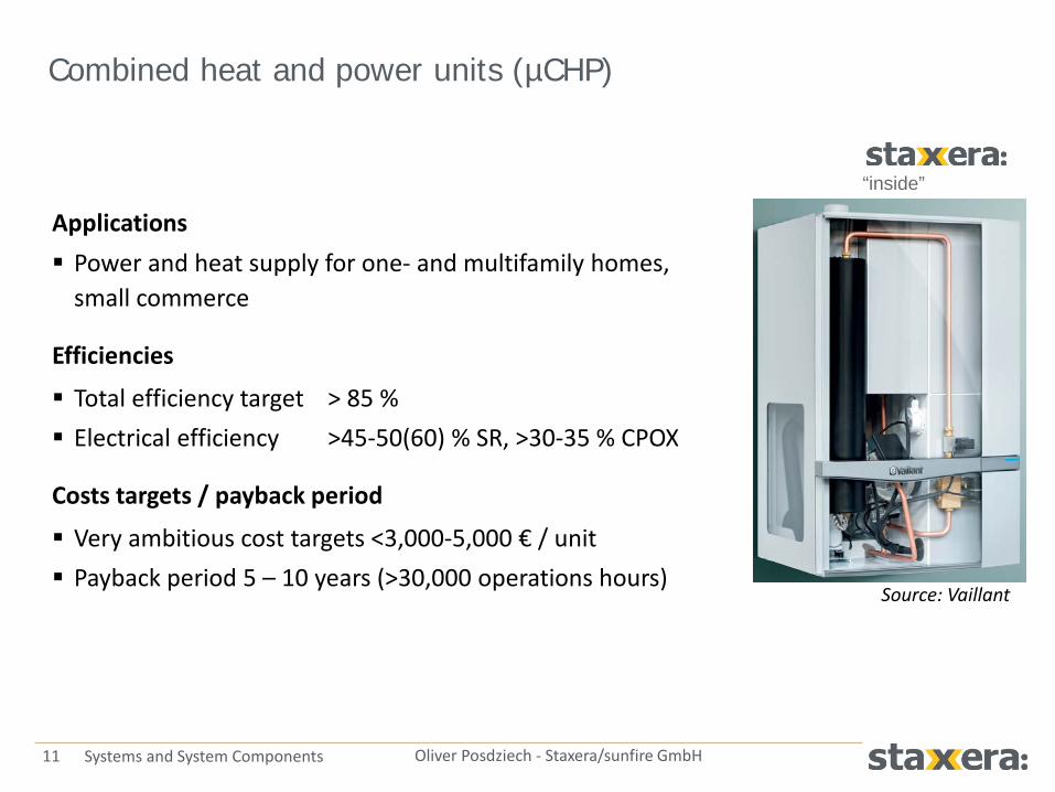
Combined heat and power units (µCHP)
Applications Power and heat supply for one- and multifamily homes,
small commerce
Efficiencies
Total efficiency target > 85 % Electrical efficiency >45-50(60) % SR, >30-35 % CPOX
Costs targets / payback period
Very ambitious cost targets <3,000-5,000 € / unit Payback period 5 – 10 years (>30,000 operations hours)
Source: Vaillant
“inside”

12 Oliver Posdziech - Staxera/sunfire GmbH Systems and System Components
Small-size combined heat and power units (smallCHP)
Applications Apartment houses, district heating, commerce,
hotels, hospitals, small industrial applications, decentral biogas units
Efficiencies Total efficiency target >85 % Electrical efficiency 50-60 % with steam reforming
Cost targets / payback period Cost targets: 1750 € / kW @ ≤100 kW; <1000 € / kW @ ≥500 kW Payback period 10 years: 60,000 operation hours
Source: Wärtsilä

13 Oliver Posdziech - Staxera/sunfire GmbH Systems and System Components
Off-grid SOFC systems
Applications Cell phones, MP3 player, digicams: 2-5 W Laptops, video cameras, electric screwdrivers:
20-100 W Leisure vehicles (caravans, yachts): 0.1-5 kW Portable military generators: 50-200 W Autarkic power generators (remote measurement systems,
alpine huts): 50 W – 20 kW Backup systems – SOFC system as main generator, electr. grid as
backup: 5-20 kW Auxiliary power units (cars, trucks): 1-5 kW Replacement of board electric generator (ships, diesel
locomotives, aircrafts): 1-20 kW
Source: eZelleron

14 Oliver Posdziech - Staxera/sunfire GmbH Systems and System Components
Off-grid SOFC systems
Fuels LPG, propane, methanol, ethanol, diesel, kerosene
Features Very fast start-up times (1-20 min) Start-up burner required, mostly battery backed High number of thermal cycles and redox cycles
Efficiencies >15 % for very small systems 25-35 % with CPOX or ATR
Cost targets / payback period Applications mostly rather cost tolerant 5 W: <200 €; 100 W: <2000 €; 350 W: <2500 €
Customer benefits Reduction of noise, range extension, low emissions
Source: eZelleron
Source: new enerday

15 Oliver Posdziech - Staxera/sunfire GmbH Systems and System Components
Auxiliary power units
Applications Mostly diesel based power generators for trucks prevents idling of main engine
Features
Electrical power output 3-5 kW Start-up time <30 min
Efficiencies
Electrical efficiency targets 25-35 % with CPOX or ATR
Cost targets / payback period
Very ambitious: 500 €/kW Price depends on competition with diesel engines
Source: Delphi

16 Oliver Posdziech - Staxera/sunfire GmbH Systems and System Components
Fuels and fuel processing

17 Oliver Posdziech - Staxera/sunfire GmbH Systems and System Components
Fuels for fuel cells
Hydrogen is the basic fuel for all fuel cells, but hydrogen must normally be derived from hydrocarbons Advantage of SOFC against other
fuel cell types: − Higher tolerance against impurities − Internal reforming capability
Fuels can be fossil (coal, diesel, gasoline, natural gas) , from waste (landfill gas, sewage gas, methanol) or from renewables (biogas) Preferred fuel depends on application (µCHP, smallCHP, off-grid, APU) Nearly all hydrocarbons need some gas processing before entering a fuel cell:
− Steam reforming (SR), catalytic partial oxidation (CPOX), oxidative steam reforming (OSR)
− Gasification

18 Oliver Posdziech - Staxera/sunfire GmbH Systems and System Components
Gaseous fuels
Natural gas Liquefied Petroleum Gas (LPG) Biogas
Application • µCHP • Small CHP • (Off-grid)
• Off-grid • µCHP
• Small CHP
Infrastructure • Extended gas grid • Worldwide supply
infrastructure • Mostly countries with
biogas subsidies
Reforming • SR, CPOX, OSR • Composition depends
on source
• SR, CPOX, OSR • Varying composition to
be taken into account
• SR, CPOX, OSR • Cleaning required
Impurities • < 5 ppmw H2S and COS • 5 … 20 ppmw odorant
(TBM, THT)
• Up to 120 ppmw sulfur • Odorized with TBM or
THT
• Depends strongly on source
• High amount of H2S

19 Oliver Posdziech - Staxera/sunfire GmbH Systems and System Components
Liquid fuels
Gasoline Diesel Kerosene
Application
• Auxiliary power unit (APU)
• Range extender for electrical cars
• Auxiliary power units • Range extender • Off-grid power supplies
• Auxiliary power units for aircrafts
• Military applications
Infrastructure • Worldwide supply infrastructure • Varying quality depending on source and refinery
Reforming • SR possible, but risk of catalyst deactivation • CPOX challenging: carbon formation, catalyst deactivation • Most promising: OSR with anode off-gas recirculation
Impurities
• Up to 80 ppm sulfur (average 30 ppmw)
• Dibenzylthiophen • Additives, complex
hydrocarbons
• Standard on sulfur content: 10 ppmw (EU), 15 ppmw (US)
• Dibenzylthiophen • Additives, complex
hydrocarbons
• Sulfur content 500-1500 ppmw
• Dibenzylthiophen • Additives, complex
hydrocarbons

20 Oliver Posdziech - Staxera/sunfire GmbH Systems and System Components
Oxygenated fuels
Ethanol Methanol Dimethyl ether (DME)
Application
• Renewable fuel • Off-grid application
• Produced from renewables or waste
• Off-grid application, smallCHP
• Renewable fuel • Off-grid application • Replacement of LPG
for µCHP?
Infrastructure
• No general infrastructure (some countries with 100 % ethanol at gas station)
• Delivery via tank truck
• No infrastructure, but delivery via tank truck
• Small canisters for off-grid (Smart Fuel Cells)
• No infrastructure, but delivery via tank truck
Reforming
• CPOX very easy • Steam reforming with
soot formation risk pre-reforming
• SR, CPOX, OSR • Low reforming
temperatures
• SR, CPOX, OSR • Methanation to be
considered
Impurities • No sulfur • Halide ions
• No sulfur • No sulfur

21 Oliver Posdziech - Staxera/sunfire GmbH Systems and System Components
Reforming types
Steam reforming (SR) Endothermic reaction supply of heat Heat is converted into fuel enthalpy high SOFC system efficiencies Low probability of carbon formation
Catalytic partial oxidation (CPOX) Exothermic reaction adiabatic operation Fuel enthalpy is converted into heat lower SOFC system efficiency Higher probability of carbon formation
and catalyst deactivation
Oxidative steam reforming (OSR) Mixture of SR and CPOX special case autothermal reforming (ATR) Decrease of carbon formation likelihood
(e.g. liquid fuels)
CnHm + n H2O ↔ n CO + (n + 0.5m) H2
CnHm + 0.5n O2 → n CO + 0.5m H2
CnHm + a H2O + b O2 ↔ c CO + d H2

22 Oliver Posdziech - Staxera/sunfire GmbH Systems and System Components
Pre-reforming
Application Usage of internal reforming
capabilities of SOFC stacks increase of electrical efficiency due to decreasing air flows Conversion of complex
hydrocarbons (diesel, gasoline, ethanol) into a light gas mixture Hydrogen generation for
desulphurization (ZnO) Conversion of higher hydrocarbons
(>C1) into CO + H2 to avoid carbon deposition at anode)
CnHm + H2O ↔ CO + H2+CH4
0
0.02
0.04
0.06
0.08
0.1
0.12
0.14
300 400 500 600 700D
ry g
as co
mpo
sitio
n / V
ol%
Temperature / °C
C2H6, exp. C3H8, exp.
Conversion of higher hydrocarbons from natural gas

23 Oliver Posdziech - Staxera/sunfire GmbH Systems and System Components
Definitions
Oxygen-to-carbon ratio defines mainly soot formation limit
O/C ratio for anode off-gas
recirculation
Steam-to-carbon ratio (ideal gas)
Air ratio / oxygen-to-carbon
ratio for CPOX
104836242
222
43222
/HCHCHCCHCOCO
OHCOCOO
nnnnnnnnnn
CO
+++++
+++=
oml
omlk
OHCCOCO
OHCOHCOO
nlnnnonnkn
CO
++
++=
2
222
/
1min,,2
2
=
=λ
λO
O
nn
N
CH
Nair
VV
4221.0
⋅⋅
=λ ( ) λ⋅=⋅⋅
= 421.02
4
NCH
Nair
VV
CO
oml OHC
OH
nln
CS
2/ = ( )
83624
2
32 HCHCCHN
NG
NOH
xxxVV
CS
⋅+⋅+=
24 Oliver Posdziech - Staxera/sunfire GmbH Systems and System Components
System concepts

25 Oliver Posdziech - Staxera/sunfire GmbH Systems and System Components
20% 25% 30% 35% 40% 45% 50% 55% 60% 65%
Fuel processing options in SOFC systems
Partial oxidation (POX)
Oxidative steam reforming (OSR)
Anode off-gas recirculation
Steam reforming (SR)
Catalytic partial oxidation (CPOX)
Thermal partial oxidation (TPOX)
Serial stack connection
Autothermal reforming (ATR)
Electrical efficiency

26 Oliver Posdziech - Staxera/sunfire GmbH Systems and System Components
CPOX based SOFC systems
10483624
2
5.655.32minHCHCHCCH
airO
air
airVVVV
Vx
VV
+++==λ
700 °C
Reformate
800 °C Off-gas burner SOFC stack
Cathode air preheater
Cathode air Exhaust
gas
CPOX reactor
800 °C
800 °C
Natural gas LPG
(Diesel) Ethanol
Biogas
CPOX air
Reformer air-to-fuel ratio

27 Oliver Posdziech - Staxera/sunfire GmbH Systems and System Components
CPOX based SOFC systems
Advantages No water required Reduced number of components Compact, adiabatic reactor
Disadvantages Electrical efficiency maximal 35 % Narrow operation window:
0.27…0.3 < λ < 0.34…0.36 (soot formation / catalyst deactivation at Tmax =950 °C) High air demand for stack cooling Costly precious metal catalyst Reformate temperature >700-750 °C needed (soot) Likelihood of soot formation if more complex
hydrocarbons are used
Applications Simple, low-cost systems µCHP, off-grid systems (NG, LPG, propane, diesel) Small-scale systems

28 Oliver Posdziech - Staxera/sunfire GmbH Systems and System Components
Oxidative steam reforming based systems
700 °C
Reformate
750 °C Off-gas burner SOFC stack Diesel
LPG Natural gas
Cathode air preheater
Cathode air Exhaust
gas
OSR reactor
Anode off-gas
800 °C
Recirculation
blower /injector
750 °C (option: cooled)
COCOCH
OHCOOCO
VVVVVVV
CO
++
+++=
24
22222
/
Oxygen-to-carbon ratio
Air Steam

29 Oliver Posdziech - Staxera/sunfire GmbH Systems and System Components
Oxidative steam reforming
Advantages Increase of electrical efficiency compared to
CPOX systems Reduction of carbon formation likelihood Reduction of reforming temperature Adiabatic reformer
Disadvantages External steam supply or anode off-gas
recirculation Measurement and control of
recirculation loop (blower, injector) Long-term stable recirculation
blower
Applications Mostly off-grid systems that
use higher hydrocarbons (LPG, diesel, gasoline) Dependent or independent
of external water supply

30 Oliver Posdziech - Staxera/sunfire GmbH Systems and System Components
Steam reforming based SOFC systems
700 °C
Reformate
800 °C Off-gas burner SOFC stack
Cathode air preheater
Cathode air Exhaust
gas
Steam reformer
800 °C
800 °C
Natural gas LPG Diesel
Reformate heater
DI water
Exhaust gas
Evaporator
Fuel preheater
+++=
83624
2
32/
HCHCCH
OH
VVVV
CS
Steam-to-carbon ratio

31 Oliver Posdziech - Staxera/sunfire GmbH Systems and System Components
Steam reforming based SOFC systems
Advantages Electrical efficiency 45-60 % Wide operation window (S/C, T) Internal reforming possible reduced air demand
Disadvantages Large number of components Costs for water processing Reliability of water supply Bad dynamic system behaviour Large catalyst volume
Applications Systems with high electrical
efficiency µCHP, large-scale systems Reforming of complex
hydrocarbons

32 Oliver Posdziech - Staxera/sunfire GmbH Systems and System Components
Anode off-gas recirculation
700 °C
Reformate
750 °C Off-gas burner SOFC stack
Natural gas
Cathode air preheater
Cathode air Exhaust
gas
SR reactor Anode off-gas
800 °C
Recirculation
blower
750 °C
COCOCH
OHCOCO
VVV
VVVCO
++
++=
24
222
/
Oxygen-to-carbon ratio

33 Oliver Posdziech - Staxera/sunfire GmbH Systems and System Components
Anode off-gas recirculation
Advantages Electrical efficiency > 50 % Closed water loop Internal reforming possible reduced air demand Low number of components
Disadvantages Recirculation blower required Measurement and control of recirculation
loop is challenging (soot formation)
Applications Systems with maximal electrical
efficiency or ATR based systems Mainly larger systems costs of
recirculation blower

34 Oliver Posdziech - Staxera/sunfire GmbH Systems and System Components
Anode off-gas recirculation: Recirculation rate
Definition of recirculation rate
Increases with O/C ratio of steam reformer O/C of steam reforming normally 2 … 2.5, successful experiments down to 1.5 (VTT)
Calculation of O/C from recirculation rate General equation:
100 % methane Biogas (CH4, CO2)
EX
RCR V
VA
=
VRC … Recirculation flow rate VEX … Exhaust gas flow rate
( )[ ] ( )( ) ( )[ ]11432
131074112/
104836242
104836242
−⋅+⋅++++
+++⋅⋅+−⋅+⋅=
fRin
HCin
HCin
HCin
CHin
CO
inHC
inHC
inHC
inCHfRfR
inCO
uAVVVVV
VVVVuAuAVCO
( )11
4/
−⋅+
⋅=
fR
fR
uA
uACO ( )[ ]
( ) ( )[ ]11
4112/
42
42
−⋅+⋅+
⋅⋅+−⋅+⋅=
fRin
CHin
CO
inCHfRfR
inCO
uAVV
VuAuAVCO
35 Oliver Posdziech - Staxera/sunfire GmbH Systems and System Components
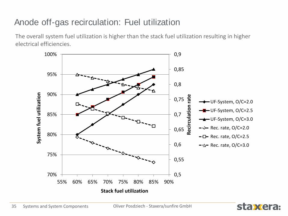
Anode off-gas recirculation: Fuel utilization The overall system fuel utilization is higher than the stack fuel utilization resulting in higher electrical efficiencies.
0,5
0,55
0,6
0,65
0,7
0,75
0,8
0,85
0,9
70%
75%
80%
85%
90%
95%
100%
55% 60% 65% 70% 75% 80% 85% 90%Re
circ
ulat
ion
rate
Syst
em fu
el u
tiliz
atio
n
Stack fuel utilization
UF-System, O/C=2.0
UF-System, O/C=2.5
UF-System, O/C=3.0
Rec. rate, O/C=2.0
Rec. rate, O/C=2.5
Rec. rate, O/C=3.0
36 Oliver Posdziech - Staxera/sunfire GmbH Systems and System Components
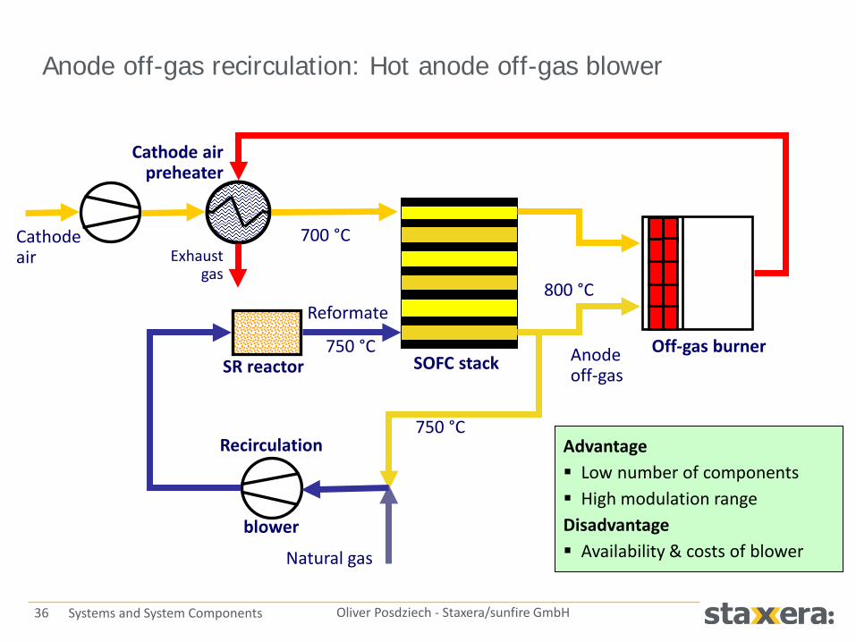
Anode off-gas recirculation: Hot anode off-gas blower
700 °C
Reformate
750 °C Off-gas burner SOFC stack
Natural gas
Cathode air preheater
Cathode air Exhaust
gas
SR reactor Anode off-gas
800 °C
Recirculation
blower
750 °C Advantage Low number of components High modulation range Disadvantage Availability & costs of blower
37 Oliver Posdziech - Staxera/sunfire GmbH Systems and System Components
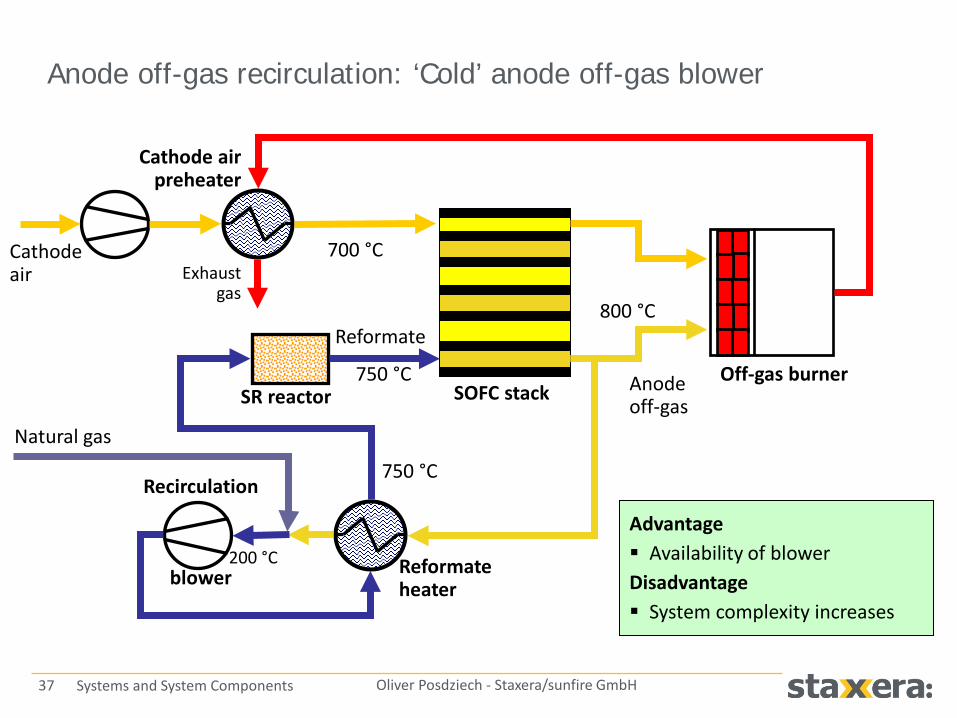
Anode off-gas recirculation: ‘Cold’ anode off-gas blower
700 °C
Reformate
750 °C Off-gas burner SOFC stack
Natural gas
Cathode air preheater
Cathode air
Reformate heater
Exhaust gas
SR reactor Anode off-gas
800 °C
Recirculation
blower 200 °C
750 °C
Advantage Availability of blower Disadvantage System complexity increases

38 Oliver Posdziech - Staxera/sunfire GmbH Systems and System Components
Anode off-gas recirculation: Ejector based recirculation
700 °C
Reformate
750 °C Off-gas burner SOFC stack
Natural gas
Cathode air preheater
Cathode air Exhaust
gas
SR reactor Anode off-gas
800 °C
Natural gas compressor
Ejector
Advantage Very simple system layout No rotating pars in hot environment Disadvantage Limited modulation range High gas inlet pressure required

39 Oliver Posdziech - Staxera/sunfire GmbH Systems and System Components
Serial connection of SOFC stacks
Two-staged system with serial connection of stacks with CPOX and steam reformer as gas processor
700 °C
750 °C
Cathode air
800 °C
800 °C
SR
CPOX
Stack 30 cells
Stack 60 cells
700 °C 20 °C
800 °C
800 °C
Natural gas
CPOX air
Natural gas

40 Oliver Posdziech - Staxera/sunfire GmbH Systems and System Components
Applications Systems with higher electrical
efficiencies (µCHP, smallCHP)
Advantages High electrical efficiencies
without water processing or anode off-gas blower Electrical efficiency > 45 %
Disadvantages Power electronics more complex Additional fluid streams Complex stack
Serial stack connection

41 Oliver Posdziech - Staxera/sunfire GmbH Systems and System Components
SOFC system design

42 Oliver Posdziech - Staxera/sunfire GmbH Systems and System Components
Design process
Basic specification
Application & market Stack & system boundary conditions
System layout
BoP components specification
Safety analysis CE requirements
Operation & control strategies
Process simulation

43 Oliver Posdziech - Staxera/sunfire GmbH Systems and System Components
System specification
Stack Fuel utilization Air and fuel inlet temperatures Reformate composition Thermal and redox cycling capabilities System Fuel quality Soot formation limits Available heat flows Start/stop procedure Control strategies Thermal losses
Application Stack and system
Requirements Electrical & thermal power output Electrical and total efficiencies Required start-up time Operation time / cycling Cost targets and payback periods Safety and certification requirements Design options Fuel processing System size Stack type Start-up strategy Components choice and costs

44 Oliver Posdziech - Staxera/sunfire GmbH Systems and System Components
System design practice
Designing a compact system Minimize heat exchanger areas “Pinch point” analysis Functional combination of components No piping between components Optimize components arrangements Stack integration in hot box
“Pinch point” analysis The pinch point is the minimal temperature difference between hot stream and cold stream in a heat exchanger. It defines the heat transfer rate and required heat exchanger area. The analysis of a system reveals critical minimal temperature differences between different streams.
Source: Delphi
SOFC system design

45 Oliver Posdziech - Staxera/sunfire GmbH Systems and System Components
Safety and CE certification
1. Off-gas burner has to guarantee that no explosive or toxic (CO) gas leaves the system Reliable start-up procedure / ignition detection Flame detection important, but difficult in SOFC systems Burner control according to standards (air ratio)
2. Components and connections in hot environments can leak Avoid mixing of air and gas (e.g. in heat exchangers) Operate gas stream in under-pressure mode exhaust gas suction blower Ventilate housing
3. Stack leakages Supply gas only if stack is above ignition temperature Purge stack environment
SOFC system design

46 Oliver Posdziech - Staxera/sunfire GmbH Systems and System Components
Safety and CE certification
Fuel Cell Standards EN 50465 Gas appliances - Fuel cell gas heating appliances - Fuel cell gas heating
appliance of nominal heat input inferior or equal to 70 kW (Classification, Construction, Operation, EMC) EN 62282 Fuel cell technologies (Safety, Test methods, Safety checks) ISO 23273 Fuel cell road vehicles including all APU (hazards inside and outside of the
vehicles caused by the fuel cell system)
SOFC system design
Gas Appliances / Burner Standards EC Gas Appliances Directive (90/396/EEC) EN 483 Gas-fired central heating boilers (requirements, construction, rational use of
energy, test methods) EN 161 Automatic shut-off valves for gas burners EN 298 Automatic gas burner control systems EN 125 Flame supervision devices EN 1854 Pressure sensing devices for gas burners
47 Oliver Posdziech - Staxera/sunfire GmbH Systems and System Components
System efficiencies

48 Oliver Posdziech - Staxera/sunfire GmbH Systems and System Components
Definitions SOFC system design
Fuel HHV in MJ/m³ LHV in MJ/m³
Hydrogen 12,745 10,783
Carbon monoxide 12,633 12,633
Natural gas 35…46 31…41
Methane 39,819 35,883
Ethane 70,293 64,345
Propane 101,242 93,215
n-Butane 134,061 123,810
LHV and HHV of typical gaseous fuels
𝜂𝑒𝑒 =𝑃𝑒𝑒𝑃𝑓𝑓𝑒𝑒
𝜂𝐷𝐷 ,𝑆𝑆𝑆𝑆𝑆 =𝑃𝐷𝐷 ,𝑆𝑆𝑆𝑆𝑆
𝑃𝑓𝑓𝑒𝑒=𝑁 × 𝑈𝑐𝑐𝑐𝑐 × 𝐼�̇�𝑓𝑓𝑒𝑒𝑁 × 𝐿𝐿𝑉
Electrical efficiency:
DC stack power (LHV=Lower Heating value): LHV is used in Europe, HHV (Higher Heating value) is normally applied in USA or Asia
DC system power: PAUX = power consumption of auxiliaries blowers, pumps, control system, valves, …
AC system power:
𝜂𝐷𝐷,𝑆𝑆𝑆𝑆𝑒𝑆 =𝑃𝐷𝐷 ,𝑆𝑆𝑆𝑆𝑆 − 𝑃𝐴𝐴𝐴
𝑃𝑓𝑓𝑒𝑒
𝜂𝐴𝐷,𝑆𝑆𝑆𝑆𝑒𝑆 = 𝜂𝐷𝐷,𝑆𝑆𝑆𝑆𝑒𝑆 × 𝜂𝐼𝐼𝐼𝑒𝐼𝑆𝑒𝐼
Thermal efficiency: Overall efficiency:
CHP coefficient:
𝜂𝑆𝑡 =�̇�𝑡𝑒𝑆𝑆𝑃𝑓𝑓𝑒𝑒
=�̇� × 𝑐𝑝 × 𝑇𝐻 − 𝑇𝐾
�̇�𝑓𝑓𝑒𝑒𝑁 × 𝐿𝐿𝑉
𝜂𝑆𝑡𝑆 = 𝜂𝑒𝑒 + 𝜂𝑆𝑡
𝜎 =𝑃𝑒𝑒�̇�𝑡𝑒𝑆𝑆

49 Oliver Posdziech - Staxera/sunfire GmbH Systems and System Components
Why high efficiencies? SOFC system design
CHP systems
High overall efficiency increases profitability
High electrical efficiency makes power feed-in attractive
High electrical efficiency increases number of operation hours
(due to limitations in heat usage)
Off-grid systems
Mostly high electrical efficiencies required
Decrease of fuel consumption:
− Reduction of fuel costs
− Range extension / operation time extension

50 Oliver Posdziech - Staxera/sunfire GmbH Systems and System Components
Electrical efficiency
Maximization of electrical efficiency Steam reforming for fuel processing
(resp. anode off-gas recirculation) Operation at high fuel utilization Reduction of power consumption of
auxiliaries: - Decrease of system pressure losses
(< 30-50…100 mbar) - Usage of internal reforming
capabilities for stack cooling - Operation of blowers at maximal efficiency - Reduction of power consumption of pumps, valves, controls
Operation of stack at high voltage (oversizing)
Ceramic Fuel Cells (CFCL) … has demonstrated electrical efficiencies of 60 % at 1.5 kW power output. This is similar to the latest generation of Combined Cycle Power Plants. The exhaust heat usage additionally allows a high overall efficiency.
SOFC system design

51 Oliver Posdziech - Staxera/sunfire GmbH Systems and System Components
Electrical efficiency
Influence of fuel processing, fuel utilization and fuel composition
SOFC system design

52 Oliver Posdziech - Staxera/sunfire GmbH Systems and System Components
Electrical efficiency
Influence of cell voltage – number of cells to generate 1500 W: ASR=0.72 Ohm/cm² (ESC technology) and 0.4 Ohm/cm² (ASC technology)
SOFC system design
Does oversizing of stacks make sense for higher electrical efficiencies? The required number of cells increases more steeply than the electrical efficiency: Amortization time of a system would increase!

53 Oliver Posdziech - Staxera/sunfire GmbH Systems and System Components
Electrical efficiency
Influence of internal reforming rate, system pressure loss and blower efficiency
SOFC system design

54 Oliver Posdziech - Staxera/sunfire GmbH Systems and System Components
Thermal efficiency
Maximization of thermal efficiency Compact system for reduction
of thermal losses High-grade insulation in hot parts Hotbox design with highest
temperatures in the core Stack integration within hotbox Avoidance of thermal bridges
low number of sensors in hot parts Condensation of exhaust gas
− Low temperature water cycle in application
− Exhaust gas with min. air ratio (high dew point)
SOFC system design
0 200 400 600 800 10000
0.05
0.1
0.15
0.2
T (°C)k
[Wm
-1K
-1]
Thermal conductivity of insulation materials
ceramic fibremicroporous #1microporous #2firebrick
Source: VTT

55 Oliver Posdziech - Staxera/sunfire GmbH Systems and System Components
Control & operation procedures

56 Oliver Posdziech - Staxera/sunfire GmbH Systems and System Components
Operational states
Represented in state diagrams Main states:
− System heat up − Normal operation (load following) − Cool down procedure − Emergency situations
Operational procedures depend on: − System design − Gas processing type − Stack type − Application (stationary, off-grid, …)
SOFC system design

57 Oliver Posdziech - Staxera/sunfire GmbH Systems and System Components
Hints on operation & control
Investigate temperature control of reactors (reformer, off-gas burner, stack) Simulate heat-up and cool-down
process Avoid start-stop cycles and fast
transients Set useful limits for system parameters
(safety checks) Check load following capability of stack
and system Minimize number of actuators Operate blowers at optimal design
conditions efficiency
0
200
400
600
800
1000
1200
0 2 4 6 8 10 12 14 16
Time [h]
Tem
pera
ture
[°C
], w
ater
flow
rate
[g/h
]
0
2
4
6
8
10
12
Fuel
sup
ply
[Nl/m
in]
T_Burner T_ReformerT_Evaporator T_StackWater flow rate NG flow rate
System heat up Can be largely simplified by using electrical devices (start-up burner not required). A reasonable option for continuously running systems.
SOFC system design

58 Oliver Posdziech - Staxera/sunfire GmbH Systems and System Components
Systems with fast start-up
System design for fast start-ups CPOX systems faster in heat up and load
following than SR based Over-dimensioning of start-up burner
required Minimize components weight Stacks based on tubular cells favorable
(lower weight) Use of stacks with high power density Close connection of start-up burner and stack
(radiative heat transfer)
Stack heat up 1 kWel
0
20
40
60
80
100
120
140
0 5 10 15 20 25Burner power / kW
Hea
t up
time
/ m
in
ESC, 50 W/kgASC, 100 W/kgMicro tubular, 200 W/kg
Portable SOFC systems and APUs require very fast start-up times. This is a challenge for SOFC technology. An underestimated fact is very often the required start-up burner capacity.
SOFC system design
59 Oliver Posdziech - Staxera/sunfire GmbH Systems and System Components
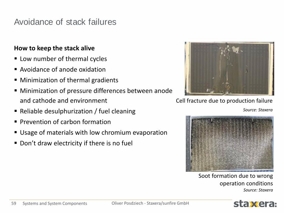
Avoidance of stack failures
How to keep the stack alive Low number of thermal cycles Avoidance of anode oxidation Minimization of thermal gradients Minimization of pressure differences between anode
and cathode and environment Reliable desulphurization / fuel cleaning Prevention of carbon formation Usage of materials with low chromium evaporation Don’t draw electricity if there is no fuel
Cell fracture due to production failure Source: Staxera
Soot formation due to wrong operation conditions
Source: Staxera
SOFC system design
60 Oliver Posdziech - Staxera/sunfire GmbH Systems and System Components
Costs & profitability

61 Oliver Posdziech - Staxera/sunfire GmbH Systems and System Components
Profitability of µCHP systems
Factors that must be taken into account for profitability calculations
Customer Load profile of heat and electricity
consumption Average and maximum loads System Electrical and total efficiencies (CHP
coefficient) load depending! Maximal electricity and heat generation Modulation (turn down ratio) Maintenance costs Utility Electricity price Fuel price Feed-in tariffs
Capital expenditure (CAPEX) Operational expenditure (OPEX)
Fuel cell system costs Costs of peak burner, water storage,
control Installation costs Capital service Depreciation period total costs of
ownership Investment supports (subsidies)

62 Oliver Posdziech - Staxera/sunfire GmbH Systems and System Components
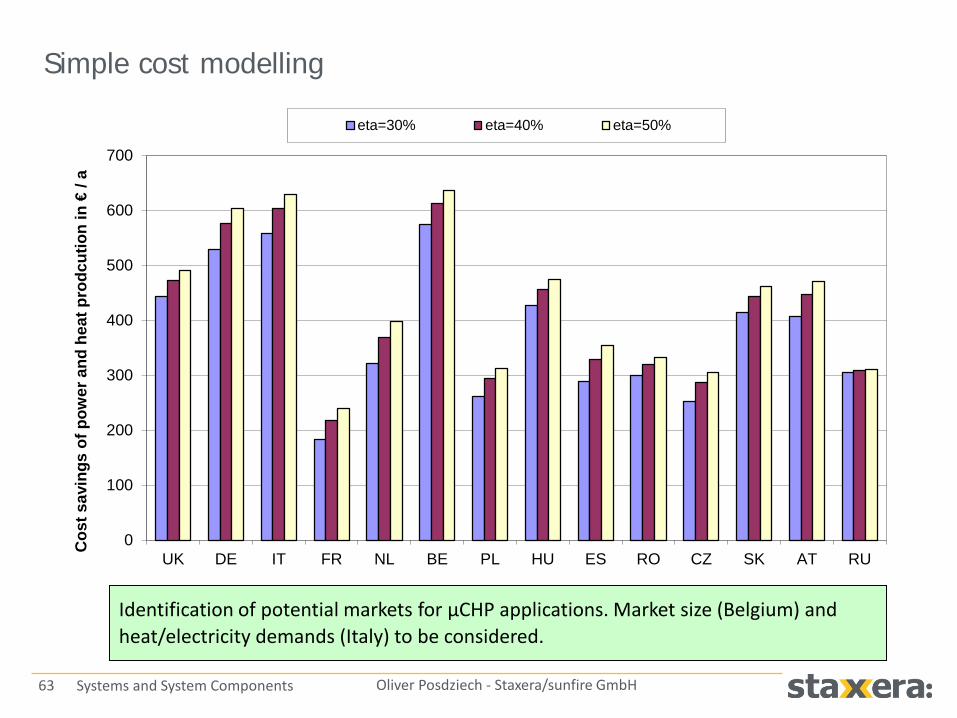
Simple cost modelling
Target Initial calculation of yearly cost
savings by CHP installation Assumptions 5000 h yearly full-load operation
hours 85 % total efficiency, variation
of electrical efficiency No maintenance costs Full usage of heat and electricity,
no feed-in of electricity Local gas and electricity prices No funding
Natural gas price Electricity price
France 40.2 €/MWh 125.6 €/MWh
Germany 43.6 €/MWh 237.5 €/MWh
Italy 47.6 €/MWh 196.7 €/MWh
Spain 41.2 €/MWh 172.8 €/MWh
United Kingdom 31.3 €/MWh 138.6 €/MWh
63 Oliver Posdziech - Staxera/sunfire GmbH Systems and System Components
Simple cost modelling
0
100
200
300
400
500
600
700
UK DE IT FR NL BE PL HU ES RO CZ SK AT RU
Cos
t sav
ings
of p
ower
and
hea
t pro
dcut
ion
in €
/ a
eta=30% eta=40% eta=50%
Identification of potential markets for µCHP applications. Market size (Belgium) and heat/electricity demands (Italy) to be considered.

64 Oliver Posdziech - Staxera/sunfire GmbH Systems and System Components
Simple modelling of µCHP systems
General High total efficiencies required for
cost effective CHP systems High electrical and thermal
efficiencies High modulation range to increase
yearly operation hours and avoid start-stop-cycles System size and CHP coefficient must
fit to heat and electricity demands
Source: Ariston/Elco (Flame-SOFC )

65 Oliver Posdziech - Staxera/sunfire GmbH Systems and System Components
Detailed cost modelling
Requires load profiles for heating system, domestic water supply and electricity consumption in Germany VDI guideline 4655 Requires data of the µCHP unit like turn down ratio and efficiencies changes
versus load, speed of load changes To be considered:
− Thermal insulation of building − Size and load of thermal storage − Feed-in tariffs including funding
Comparison of CFCL “BlueGen” and Hexis “Galileo 1000 N”
Business cases should work without funding (only in market penetration period). Changes in funding politics are likely.

66 Oliver Posdziech - Staxera/sunfire GmbH Systems and System Components
Basic assumptions for cost
Single-family home (2005) new house, low heat demand Peak boiler: ηth = 0.85 Electricity price (Dresden): 0.231 €/kWh Natural gas price (Dresden): 0.086 €/kWhLHV
Thermal Storage System:
λ [W/m²K] 0,03d [m] 0,1V [m³] 0,5Qleakage [kWh] 1,28Qstorage [kWh] 11,64
∆T [K] 35
isolationheat conductivity
thermal storage system sizeleakage heat per daystorable heatdifference in temperature(storage and installation location)

67 Oliver Posdziech - Staxera/sunfire GmbH Systems and System Components
Cases to be compared
1) Including German CHP-funding a) Powered in the summer period b) Disabled in the summer period
2) Excluding German CHP-funding
a) Powered in the summer period b) Disabled in the summer period
3) Operation regimes of BlueGen:
a) Heat driven (HD) b) Electricity driven (ED)
CFCL - BlueGen µCHP unit
Max. electrical load 2.0 kW
Electricity to heat ratio σ 2
Max. thermal load 1.0 kW
Peak burner power 5.0 kW
Electrical efficiency 60 % @ 1500 W
Overall efficiency 85 %
Modulation range 20 … 100 %
Hexis - Galileo 1000 N µCHP unit
Max. electrical load 1.0 kW
Electricity to heat ratio σ 0.4
Max. thermal load 2.5 kW
Peak burner power 5.0 kW
Electrical efficiency 35 %
Overall efficiency 90 %
Modulation range 33 … 100 %

68 Oliver Posdziech - Staxera/sunfire GmbH Systems and System Components
BlueGen: Thermal Demand and Generation (heat driven)
Example week in the transition period
0,0
1,0
2,0
3,0
4,0
5,0
6,0
Monday
Tuesday
Wednes
day
Thursday
Friday
Saturday
Sunday
P [kW]
0
2
4
6
8
10
12
14
Q [kWh]Pth,con,cur.br. [kW]Pth,gen,CHPplant [kW]Pth,gen,ad.br. [kW]Qth,HS,diff [kWh]

69 Oliver Posdziech - Staxera/sunfire GmbH Systems and System Components
BlueGen: Electrical Demand and Generation (heat driven)
Example week in the transition period
0,00
0,50
1,00
1,50
2,00
2,50
Monday Tuesday Wednesday Thursday Friday Saturday Sunday
P [kW] Pel,con,cur.br. [kW]Pel,gen,CHPplant [kW]

70 Oliver Posdziech - Staxera/sunfire GmbH Systems and System Components
BlueGen: Electrical Demand and Generation (electricity driven)
Example week in the transition period
0,00
0,50
1,00
1,50
2,00
2,50
Monday Tuesday Wednesday Thursday Friday Saturday Sunday
P [kW] Pel,con,cur.br. [kW]Pel,gen,CHPplant [kW]

71 Oliver Posdziech - Staxera/sunfire GmbH Systems and System Components
Galileo 1000 N: Electrical Demand and Generation (heat driven)
Example week in the transition period
0,00
0,50
1,00
1,50
2,00
2,50
Monday Tuesday Wednesday Thursday Friday Saturday Sunday
P [kW] Pel,con,cur.br. [kW]Pel,gen,CHPplant [kW]

72 Oliver Posdziech - Staxera/sunfire GmbH Systems and System Components
Overall yearly savings
Operation mode
Opera-tion in summer period
German CHP funding
Annual saving potential in €
Heat driven Enabled Enabled 830
Disabled 569
Disabled Enabled 788
Disabled 539
Operation mode
Opera-tion in summer period
German CHP funding
Annual saving potential in €
Heat driven Enabled Enabled 1267
Disabled 501
Disabled Enabled 1072
Disabled 403
Electricity driven
Enabled Enabled 1202
Disabled 866
Disabled Enabled 1009
Disabled 729
CFCL - BlueGen
Hexis – Galileo 1000 N

73 Oliver Posdziech - Staxera/sunfire GmbH Systems and System Components
Cost reduction options of SOFC systems
Option for cost reductions Low number of components Minimize components sizes,
apply cheaper materials Simple control algorithms Mass manufacturing of
components Integration of standard
components from heating or automotive industry
Cost reduction curve for Staxera’s stacks and stack & stack modules (data 2009)

74 Oliver Posdziech - Staxera/sunfire GmbH Systems and System Components
Balance of Plant components

75 Oliver Posdziech - Staxera/sunfire GmbH Systems and System Components
Typical SOFC system
Reformer
Evaporator
Afterburner SOFC
Heat recovery unit
Air preheater
Fuel preheater
Desulphurizer
stack
Inverter Control system
Blower Flow sensor
Water pump Flow sensor Deionization
Gas valve Flow sensor

76 Oliver Posdziech - Staxera/sunfire GmbH Systems and System Components
BoP requirements
Safe operation
High stability, low drift
Certification where applicable
Long life-time (> 40,000-60,000 h)
No harming of downstream components - Anode poisoning with sulfur - Anode coking - Cathode poisoning with chromium
Cold BoP Blowers, pumps Sensors (temperature, pressure, flame
detection, gas concentration, flow) Gas and water valves Desulphurization Control & safety electronics Power electronics
Hot BoP Reforming unit Heat exchangers / evaporator Start-up and afterburner

77 Oliver Posdziech - Staxera/sunfire GmbH Systems and System Components
Reformer
Steam reforming (SR) Endothermic reaction heat supply GHSV = 5,000…10,000 h-1
Catalyst volume mostly larger due to heat transfer requirement Catalyst used as pellets, coated heat
exchanger plates or coated meshes
Catalytic partial oxidation (CPOX) Exothermic reaction GHSV = 50,000…100,000 h-1
Mostly monoliths used
Catalysts Nickel/copper (low costs) or noble metal
Pt, Pl, Rh (stability, oxidizing atmosphere) Sulphur tolerance only useful if stack does
not degrade due to sulphur Operation at low S/C or O/C ratios
increases system efficiency Selective cracking of higher hydrocarbons
preferred for steam (pre-) reforming
catalyst
Ntotal
VVGHSV
=Reactor dimensioning – “gas hourly space velocity (GHSV)”
Heat supply Fuel/steam
mixture Reformate
Source: Behr
Fuel/air mixture Reformate

78 Oliver Posdziech - Staxera/sunfire GmbH Systems and System Components
Typical reformate compositions
Reformate composition versus temperature after CPOX reaction of methane (O/C=1.2)
0
10
20
30
40
50
60
70
80
300 400 500 600 700 800
Dry g
as co
mpo
sitio
n / V
ol%
Temperature / °C
H2, exp. H2, sim. CH4, exp. CH4, sim.Hydrogen and methane content versus temperature for stream reforming reaction of methane (S/C=2.0)

79 Oliver Posdziech - Staxera/sunfire GmbH Systems and System Components
Heat exchanger applications
Preheating of gases for fuel processing: - Gas preheater / CPOx air preheater - Reformer heat exchanger - Cathode air heater
Evaporator for steam supply
Cooling down of exhaust (off-) gases
Condensator for water recovery
Gas cooler
Gas/gas heat exchanger

80 Oliver Posdziech - Staxera/sunfire GmbH Systems and System Components
Requirements
Challenges High thermal stresses due to temperature differences Compact heat exchangers with low thermal losses Integration in hot areas of system
Pressure losses to be minimized Power demand of blowers decreases, system efficiency
increases SOFC stacks not gas tight reduce differential pressure
Materials Materials have to withstand up to 850°C (anode off-gas) /
1000°C (afterburner) Usage of high-grade alloys/stainless steels or ceramics Corrosion and chromium evaporation needs attention
Material probe after 5000 h operation with reformate
Material probe after 5000 h operation with cathode air

81 Oliver Posdziech - Staxera/sunfire GmbH Systems and System Components
Burners in SOFC systems
Application Provision of heat for the system start-up Afterburning of anode off-gases Auxiliary or peak load burner
Demands High modulation range (flow rates,
amount of combustibles) Afterburning of low and high calorific gases Long lifetime Safe operation (flame detection!)
Burner types Catalytic or volumetric (porous media,
FLOX burner, …)

82 Oliver Posdziech - Staxera/sunfire GmbH Systems and System Components
Anode off-gas afterburner
Cathode air
650 °C
Reformate
700 °C
Cathode air
800 °C
Anode off-gas
800 °C
Exhaust gas
900 °C – 1200 °C
Cathode air
650 °C
Reformate
700 °C
Cathode air
800 °C
Anode off-gas
800 °C Exhaust gas
Burner air
20 °C
900 °C – 1200 °C
1) Diffusion burner
2) Premix burner

83 Oliver Posdziech - Staxera/sunfire GmbH Systems and System Components
Emissions porous media burner
EN 62282: CO < 615 mg/kWh (300 ppm) in case of malfunction ‘Blue Angel’ (German emissions label): 50 mg/kWh CO / 60 mg/kWh NOx

84 Oliver Posdziech - Staxera/sunfire GmbH Systems and System Components
Blowers
Blower applications Supply of air to the cathode, gas/air to the anode, suction of
exhaust gas and anode off-gas recirculation Side channel blowers or centrifugal blowers used Requirements Air blower is the main consumer of electricity Considerable impact on overall electrical efficiency
Several 10,000 hours of continuous operation Pressure losses and design point have to be known for blower
specification Typical efficiencies - 60 … 80 % large blowers
- 50 … 60 % middle sized blowers - 30 … 50 % small blowers - 25 … 30 % side channel blowers

85 Oliver Posdziech - Staxera/sunfire GmbH Systems and System Components
Anode off-gas recirculation
Objectives Water supply (recovery) for steam reforming
process reduction of operation costs Increase of system efficiency due
to higher overall fuel utilization
Challenges Temperatures up to 800 °C Hydrogen leakages Reliable measurement of recirculation rates soot formation
Safety (certification) and reliability
Variants TBlower = 600 ... 800 °C Gas/gas heat exchanger TBlower < 200 °C
Source: R&D Dynamics Cooperation
Suppliers R&D Dynamics (USA) Cap Co (Japan) Prototypes ca. US-$ 50 T Long-term stability open

86 Oliver Posdziech - Staxera/sunfire GmbH Systems and System Components
Desulphurizer
Active component Operation temperature Active carbon Ambient Impregnated active carbon Ambient Zinc oxide 350-400 °C Copper oxide 100-170 °C Nickel, nickel oxide Ambient Molecular sieves Ambient Zeolite Ambient
TBM / H2S / COS easy to remove
THT causes higher costs
DMS (Japan/UK) difficult
DBT in liquid fuels very challenging
Co-adsorption of benzene needs attention toxic waste
ZnO with highest sorption capacity, but integration more difficult

87 Oliver Posdziech - Staxera/sunfire GmbH Systems and System Components
Thank you for your attention


