Low-cost Position and Force Measurement System for
Payload Transport Using UAVs
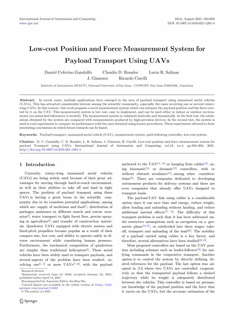
Daniel Ceferino Gandolfo Claudio D. Rosales Lucio R. Salinas J. Gimenez Ricardo Carelli
Institute of Automation (INAUT), National University of San Juan − CONICET, San Juan J5400ARL, Argentina
Abstract: In recent years, multiple applications have emerged in the area of payload transport using unmanned aerial vehicles(UAVs). This has attracted considerable interest among the scientific community, especially the cases involving one or several rotary-wing UAVs. In this context, this work proposes a novel measurement system which can estimate the payload position and the force exer-ted by it on the UAV. This measurement system is low cost, easy to implement, and can be used either in indoor or outdoor environ-ments (no sensorized laboratory is needed). The measurement system is validated statically and dynamically. In the first test, the estim-ations obtained by the system are compared with measurements produced by high-precision devices. In the second test, the system isused in real experiments to compare its performance with the ones obtained using known procedures. These experiments allowed to drawinteresting conclusions on which future research can be based.
Citation: D. C. Gandolfo, C. D. Rosales, L. R. Salinas, J. Gimenez, R. Carelli. Low-cost position and force measurement system forpayload Transport using UAVs. International Journal of Automation and Computing, vol.18, no.4, pp.594–604, 2021.http://doi.org/10.1007/s11633-021-1281-4
1 Introduction
Currently, rotary-wing unmanned aerial vehicles
(UAVs) are being widely used because of their great ad-
vantages for moving through hard-to-reach environment,
as well as their abilities to take off and land in tight
spaces. The problem of payload transport using these
UAVs is having a great boom in the scientific com-
munity due to its countless potential applications, among
which are: supply of medicines and food[1], distribution of
packages, assistance in different search and rescue scen-
arios[2], water transport to fight forest fires, precise spray-
ing in agriculture[3], and transfer of construction materi-
als. Quadrotor UAVs equipped with electric motors and
fixed-pitch propellers became popular as a result of their
compact size, low cost, and ability to operate safely in di-
verse environment while considering human presence.
Furthermore, the mechanical composition of quadrotors
are simpler than traditional helicopters[4]. These aerial
vehicles have been widely used to transport payloads, and
several aspects of the problem have been studied; in-
volving one[5, 6] or more UAVs[7−10], with the payload
anchored to the UAV[11, 12] or hanging from cables[13], us-
ing kinematic[14] or dynamic[15] controllers, with or
without obstacle avoidance[14], among other considera-
tions[16]. There are companies dedicated to developing
autonomous products for delivery systems and there are
even companies that already offer UAVs designed to
transport loads.
The payload-UAV link using cables is a considerable
option since it can save time and energy, reduce weight,
allow loading and unloading without landing, and reduce
additional inertial effects[17, 18]. The difficulty of this
transport problem is such that it has been addressed un-
der restrictive assumptions such as navigation on a geo-
metric plane[19−21], or subdivided into three stages: take-
off, transport and unloading of the load[22]. The stability
of a payload carried using cables is a key factor, and
therefore, several alternatives have been studied[23−25].
Most proposed controllers are based on the UAV posi-
tion including schemes such as leader-follower[12] for uni-
fying commands in the cooperative transport. Another
option is to control the system by directly defining de-
sired references for the payload. The last option was ad-
opted in [14] where two UAVs are controlled cooperat-
ively so that the transported payload follows a desired
trajectory while its weight is adequately distributed
between the vehicles. This controller is based on perman-
ent knowledge of the payload position and the force that
it exerts on the UAVs, but the accurate estimation of the
Research Article
Manuscript received June 12, 2020; accepted January 22, 2021;published online April 13, 2021Recommended by Associate Editor Jin-Hua She
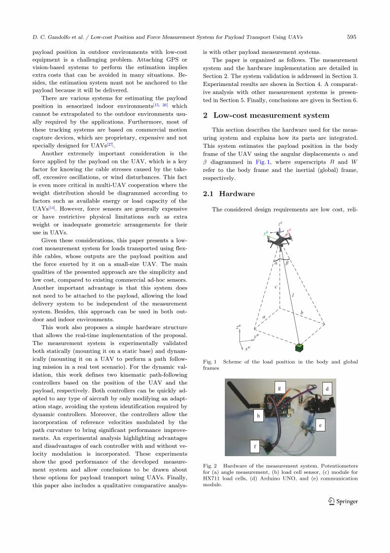
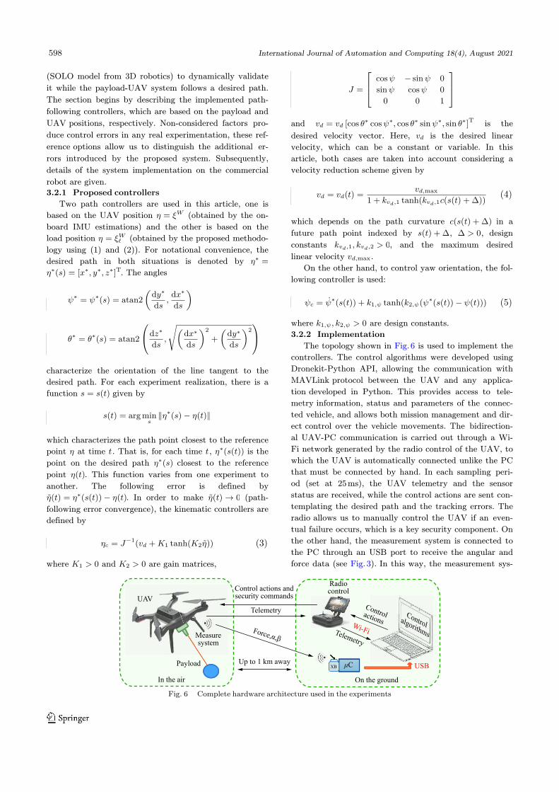
The topology shown in Fig. 6 is used to implement the
controllers. The control algorithms were developed using
Dronekit-Python API, allowing the communication with
MAVLink protocol between the UAV and any applica-
tion developed in Python. This provides access to tele-
metry information, status and parameters of the connec-
ted vehicle, and allows both mission management and dir-
ect control over the vehicle movements. The bidirection-
al UAV-PC communication is carried out through a Wi-
Fi network generated by the radio control of the UAV, to
which the UAV is automatically connected unlike the PC
that must be connected by hand. In each sampling peri-
od (set at 25 ms), the UAV telemetry and the sensor
status are received, while the control actions are sent con-
templating the desired path and the tracking errors. The
radio allows us to manually control the UAV if an even-
tual failure occurs, which is a key security component. On
the other hand, the measurement system is connected to
the PC through an USB port to receive the angular and
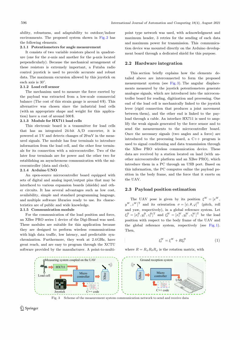
force data (see Fig. 3). In this way, the measurement sys-
UAV
In the air
Payload
Measuresystem
Control actions andsecurity commands
Radiocontrol
On the ground
Controlactions
Telemetry
Wi-Fi
Telemetry
Force,α,β
Up to 1 km awayUSBXB μC
Controlalgorithms
Fig. 6 Complete hardware architecture used in the experiments
598 International Journal of Automation and Computing 18(4), August 2021
tem allows us to know the relative payload-UAV posi-
tion during the flight execution.
3.2.3 Dynamic validation
This section presents the experiments of the control-
lers detailed in Section 3.2.1, which differ in that one is
based on the UAV position and the other is based on the
payload position. The first option is the most used in the
literature, so a similar performance between these con-
trollers implies a dynamic validation of the proposed
measurement system.
x y
The distance between the paths followed by the UAV
and the payload should be approximately equal to the
cable length. Besides, as the payload is transported by a
single UAV, the projection of these paths on the -
plane should be similar if the UAV moves at low velocity
and there are no external factors (such as wind) generat-
ing oscillations. However, these considerations begin to be
false if the navigation velocity increases or undesired load
oscillations appear, which would indicate that it is better
to control based on the load position. On the other hand,
reducing payload position errors is less straightforward
than reducing tracking errors in the UAV position due to
the sub-actuated characteristics of the system. Thus,
there are two options for the payload to follow a desired
path:
Option A: Define a desired path for the UAV rais-
ing the desired path for the payload a distance equal to
the cable length, and follow it with the controller (3)
based on the UAV position. This is the most common op-
tion in the literature.
Option B: Directly define a desired path for the pay-
load, and follow it using the controller (3) based on the
payload position estimated with the proposed system.
If the proposed system works correctly, then it should
be similar to navigate under Option A or B. For compar-
ative purposes, two experiments are performed consider-
ing the same reference paths and controller gains. The
reference path is defined as a challenging eight-way shape
at constant altitude to properly test the proposed system.
In addition, the force exerted by the load in both cases is
also monitored online, since the force oscillations reflect
an unstable load transport.
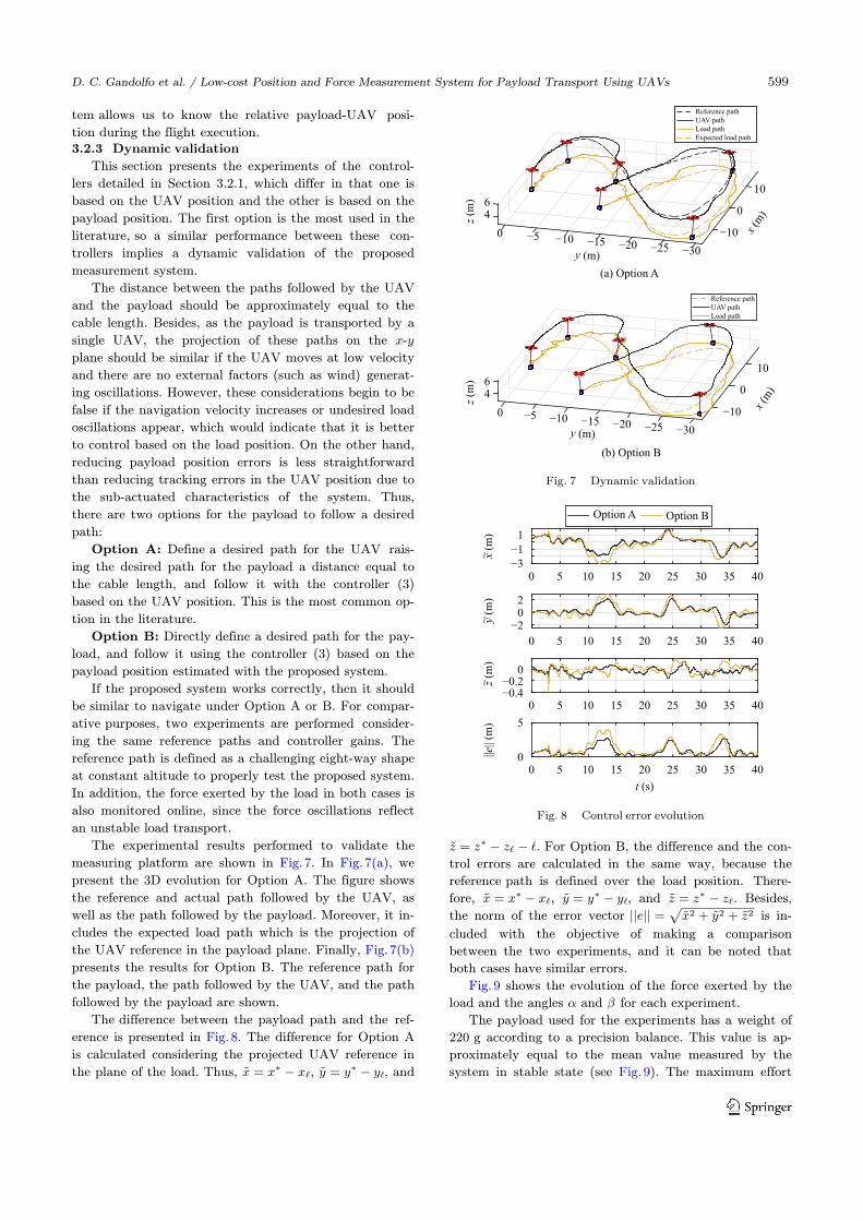
The experimental results performed to validate the
measuring platform are shown in Fig. 7. In Fig. 7(a), we
present the 3D evolution for Option A. The figure shows
the reference and actual path followed by the UAV, as
well as the path followed by the payload. Moreover, it in-
cludes the expected load path which is the projection of
the UAV reference in the payload plane. Finally, Fig. 7(b)
presents the results for Option B. The reference path for
the payload, the path followed by the UAV, and the path
followed by the payload are shown.
x = x∗ − xℓ y = y∗ − yℓ
The difference between the payload path and the ref-
erence is presented in Fig. 8. The difference for Option A
is calculated considering the projected UAV reference in
the plane of the load. Thus, , , and
z = z∗ − zℓ − ℓ
x = x∗ − xℓ y = y∗ − yℓ z = z∗ − zℓ||e|| =
√x2 + y2 + z2
. For Option B, the difference and the con-
trol errors are calculated in the same way, because the
reference path is defined over the load position. There-
fore, , , and . Besides,
the norm of the error vector is in-
cluded with the objective of making a comparison
between the two experiments, and it can be noted that
both cases have similar errors.
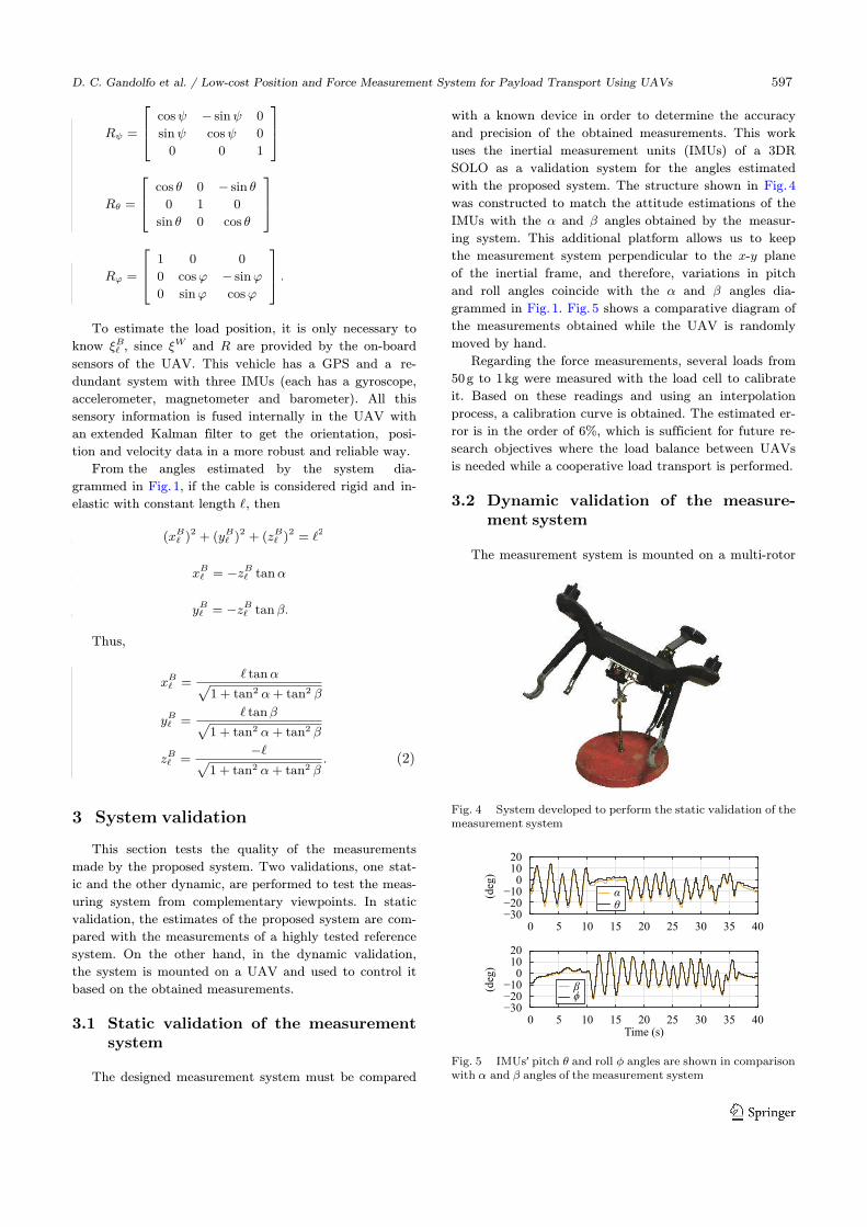
α β
Fig. 9 shows the evolution of the force exerted by the
load and the angles and for each experiment.
The payload used for the experiments has a weight of
220 g according to a precision balance. This value is ap-
proximately equal to the mean value measured by the
system in stable state (see Fig. 9). The maximum effort
10
04
z (m
)z
(m)
x (m
)
x (m
)
6
−100 −5 −10 −15 −20 −25 −30
(a) Option A
(b) Option B
10
046
−100 −5 −10 −15 −20 −25 −30y (m)
y (m)
Reference path
UAV path
Load path
Expected load path
Reference path
UAV path
Load path
Fig. 7 Dynamic validation
x (
m)
~y (
m)
~z
(m)
~||e
|| (m
)
−3−11
−202
−0.4−0.2
0
00
5
5 10t (s)
15 20 25 30 35 40
0 5 10 15 20 25 30 35 40
0 5 10 15 20 25 30 35 40
0 5 10 15 20
Option A Option B
25 30 35 40
Fig. 8 Control error evolution
D. C. Gandolfo et al. / Low-cost Position and Force Measurement System for Payload Transport Using UAVs 599
occurs at the take-off of the UAV, which corresponds to
twice the payload weight. As can be seen in these prelim-
inary experiments, the developed measuring system has a
good dynamic behavior and the proposed hardware archi-
tecture exhibits a good performance.
4 Experimental results and discussions
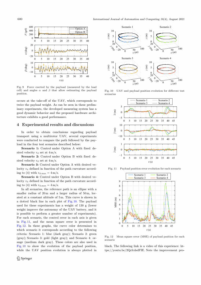
In order to obtain conclusions regarding payload
transport using a multirotor UAV, several experiments
were conducted to compare the path followed by the pay-
load in the four test scenarios described below:
vd
Scenario 1: Control under Option A with fixed de-
sired velocity set at 4 m/s.
vd
Scenario 2: Control under Option B with fixed de-
sired velocity set at 4 m/s.
vdvd,max = 4
Scenario 3: Control under Option A with desired ve-
locity defined in function of the path curvature accord-
ing to (4) with m/s.
vdvd,max = 4
Scenario 4: Control under Option B with desired ve-
locity defined in function of the path curvature accord-
ing to (4) with m/s.
In all scenarios, the reference path is an ellipse with a
smaller radius of 20 m and a larger radius of 50 m, loc-
ated at a constant altitude of 5 m. This curve is shown in
a dotted black line in each plot of Fig. 10. The payload
used for these experiments has a weight of 130 g (lower
weight improve the autonomy of the UAV battery, and it
is possible to perform a greater number of experiments).
For each scenario, the control error in each axis is given
in Fig. 11, and the mean square error is presented in
Fig. 12. In these graphs, the curve color determines to
which scenario it corresponds according to the following
criteria: Scenario 1: blue (dark gray); Scenario 2: green
(gray); Scenario 3: gold (light gray); and Scenario 4: or-
ange (medium dark gray). These colors are also used in
Fig. 10 to show the evolution of the payload position,
while the UAV position evolution is always plotted in
black. The following link is a video of this experience: ht-
tps://youtu.be/2QcfcdsdFIE. Note the improvement pro-
F (
grf
)α
(deg
)β
(deg
)
0 5 10
t (s)
15 20 25 30 35 40
0 5 10 15 20 25 30 35 40
0 5 10 15 20 25 30 35 400
200
400
600
−20
0
20
−10
0
10
Option B
Option A
α βFig. 9 Force exerted by the payload (measured by the loadcell) and angles and that allow estimating the payloadposition.
020
5
0
10
10050
Scenario 1
−200
z (m
)
y (m)
x (m)
020
5
0
10
10050
Scenario 2
−200
z (m
)
y (m)
x (m)
020
5
0
10
10050
Scenario 3
−200
z (m
)
y (m)
x (m)
020
5
0
10
10050
Scenario 4
−200
z (m
)
y (m)
x (m)
Fig. 10 UAV and payload position evolution for different testscenarios
−5
0
5
−10
0
10
−1
0
1
z (m
)~
y (
m)
~x (
m)
~
0 5 10t (s)
15 20 25 30 35 4540
0 5 10 15 20 25 30 35 4540
0 5 10 15 20
Scenario 1 Scenario 2Scenario 3 Scenario 4
25 30 35 4540
Fig. 11 Payload position error evolution for each scenario
0
MS
E (
m)
0 5 10
t (s)
15 20 25 30 35 4540
Scenario 1 Scenario 2Scenario 3 Scenario 4
1
2
3
4
5
6
7
8
9
Fig. 12 Mean square error (MSE) of payload position for eachscenario
600 International Journal of Automation and Computing 18(4), August 2021
duced by the proposed velocity reduction (Scenarios 3
and 4). Furthermore, the greatest errors are observed in
the most curved zones of the desired reference path high-
lighting the need to incorporate control strategies with
velocity modulated by geometric issues.
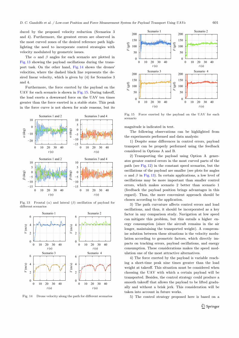
α βThe and angles for each scenario are plotted in
Fig. 13 showing the payload oscillations during the trans-
port task. On the other hand, Fig. 14 shows the drones′velocities, where the dashed black line represents the de-
sired linear velocity, which is given by (4) for Scenarios 3
and 4.
Furthermore, the force exerted by the payload on the
UAV for each scenario is shown in Fig. 15. During takeoff,
the load exerts a downward force on the UAV ten times
greater than the force exerted in a stable state. This peak
in the force curve is not shown for scale reasons, but its
magnitude is indicated in text.
The following observations can be highlighted from
the experiments performed and data analysis:
1) Despite some differences in control errors, payload
transport can be properly performed using the feedback
considered in Options A and B.
α β
2) Transporting the payload using Option A gener-
ates greater control errors in the most curved parts of the
path (see Fig. 12) in the constant speed scenarios, but the
oscillations of the payload are smaller (see plots for angles
and in Fig. 13). In certain applications, a low level of
oscillations may be more important than smaller control
errors, which makes scenario 2 better than scenario 1
(feedback the payload position brings advantages in this
regard). Thus, the more convenient approach should be
chosen according to the application.
3) The path curvature affects control errors and load
oscillations, and thus, it should be incorporated as a key
factor in any comparison study. Navigation at low speed
can mitigate this problem, but this entails a higher en-
ergy consumption (since the aircraft remains in the air
longer, maintaining the transported weight). A comprom-
ise solution between these situations is the velocity modu-
lation according to geometric factors, which directly im-
pacts on tracking errors, payload oscillations, and energy
consumption. These considerations makes the speed mod-
ulation one of the most attractive alternatives.
4) The force exerted by the payload is variable reach-
ing a short-time peak nine times greater than the load
weight at takeoff. This situation must be considered when
choosing the UAV with which a certain payload will be
transported. Besides, the control strategy could produce a
smooth takeoff that allows the payload to be lifted gradu-
ally and without a brisk jerk. This consideration will be
taken into account in future works.
5) The control strategy proposed here is based on a
t (s)
0
α (d
eg)
α (d
eg)
β (d
eg)
β (d
eg)
10 20 30 40
t (s)
0 10 20 30 40
−20
−10
0
10
−15−10−5
0
510
Scenarios 1 and 2 Scenarios 3 and 4
t (s)
0 10 20 30 40
t (s)
0 10 20 30 40
Scenarios 1 and 2 Scenarios 3 and 4
−15−10−5
0
510
−15−10−5
0
510
α βFig. 13 Frontal ( ) and lateral ( ) oscillation of payload for
different scenarios
0
V (
m/s
)V
(m
/s)
V (
m/s
)V
(m
/s)
2
4
6
0
2
4
6
0
2
4
6
0
2
4
6
0 10 20 30 40 0 10 20 30 40
t (s)
0 10 20 30 40
t (s)
0 10 20 30 40
Scenario 1 Scenario 2
Scenario 3 Scenario 4
t (s) t (s)
Fig. 14 Drone velocity along the path for different scenarios
0
50
100
150
200
0
50
100
150
200
0
50
100
150
200
0
50
100
150
200
F (
grf
)F
(grf
)
F (
grf
)F
(grf
)
0 10 20 30 40 0 10 20 30 40
t (s)
0 10 20 30 40
t (s)
0 10 20 30 40
Scenario 1 Scenario 2
Scenario 3 Scenario 4
t (s) t (s)
Fig. 15 Force exerted by the payload on the UAV for eachscenario
D. C. Gandolfo et al. / Low-cost Position and Force Measurement System for Payload Transport Using UAVs 601
kinematic model of the UAV. Its great virtue is the sim-
plicity and flexibility to be adapted to other types of air-
craft. However, dynamic offsets of the UAV-payload sys-
tem can be taken into account to achieve a better per-
formance. This type of compensation is under study and
will be considered in a future work.
5 Comparative analysis with otherpayload measurement systems
As mentioned before, an increasing number of re-
search groups have been studying payload transport sys-
tems using one or multiple UAVs, especially in the last
ten years. Focusing in the studies with experimental res-
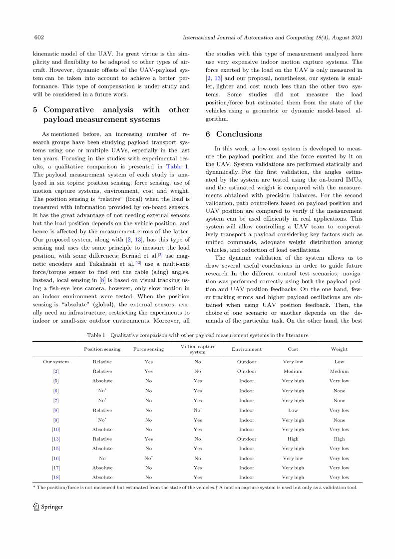
ults, a qualitative comparison is presented in Table 1.
The payload measurement system of each study is ana-
lyzed in six topics: position sensing, force sensing, use of
motion capture systems, environment, cost and weight.
The position sensing is “relative” (local) when the load is
measured with information provided by on-board sensors.
It has the great advantage of not needing external sensors
but the load position depends on the vehicle position, and
hence is affected by the measurement errors of the latter.
Our proposed system, along with [2, 13], has this type of
sensing and uses the same principle to measure the load
position, with some differences; Bernad et al.[2] use mag-
netic encoders and Takahashi et al.[13] use a multi-axis
force/torque sensor to find out the cable (sling) angles.
Instead, local sensing in [8] is based on visual tracking us-
ing a fish-eye lens camera, however, only slow motion in
an indoor environment were tested. When the position
sensing is “absolute” (global), the external sensors usu-
ally need an infrastructure, restricting the experiments to
indoor or small-size outdoor environments. Moreover, all
the studies with this type of measurement analyzed here
use very expensive indoor motion capture systems. The
force exerted by the load on the UAV is only measured in
[2, 13] and our proposal, nonetheless, our system is smal-
ler, lighter and cost much less than the other two sys-
tems. Some studies did not measure the load
position/force but estimated them from the state of the
vehicles using a geometric or dynamic model-based al-
gorithm.
6 Conclusions
In this work, a low-cost system is developed to meas-
ure the payload position and the force exerted by it on
the UAV. System validations are performed statically and
dynamically. For the first validation, the angles estim-
ated by the system are tested using the on-board IMUs,
and the estimated weight is compared with the measure-
ments obtained with precision balances. For the second
validation, path controllers based on payload position and
UAV position are compared to verify if the measurement
system can be used efficiently in real applications. This
system will allow controlling a UAV team to cooperat-
ively transport a payload considering key factors such as
unified commands, adequate weight distribution among
vehicles, and reduction of load oscillations.
The dynamic validation of the system allows us to
draw several useful conclusions in order to guide future
research. In the different control test scenarios, naviga-
tion was performed correctly using both the payload posi-
tion and UAV position feedbacks. On the one hand, few-
er tracking errors and higher payload oscillations are ob-
tained when using UAV position feedback. Then, the
choice of one scenario or another depends on the de-
mands of the particular task. On the other hand, the best
Table 1 Qualitative comparison with other payload measurement systems in the literature
Position sensing Force sensingMotion capture
systemEnvironment Cost Weight
Our system Relative Yes No Outdoor Very low Low
[2] Relative Yes No Outdoor Medium Medium
[5] Absolute No Yes Indoor Very high Very low
[6] No* No Yes Indoor Very high None
[7] No* No Yes Indoor Very high None
[8] Relative No No† Indoor Low Very low
[9] No* No Yes Indoor Very high None
[10] Absolute No Yes Indoor Very high Very low
[13] Relative Yes No Outdoor High High
[15] Absolute No Yes Indoor Very high Very low
[16] No No* No Indoor Very low Very low
[17] Absolute No Yes Indoor Very high Very low
[18] Absolute No Yes Indoor Very high Very low
* The position/force is not measured but estimated from the state of the vehicles.† A motion capture system is used but only as a validation tool.
602 International Journal of Automation and Computing 18(4), August 2021
results (in terms of tracking errors and oscillations) are
obtained in scenarios with speed reductions based on geo-
metric issues. Considering these experiments, the use of
control strategies that modulate the transport speed is re-
commended to obtain a better cost-benefit ratio between
tracking errors, oscillations, and energy consumption. Be-
sides, the forces the UAV is subjected to at takeoff are
much greater than the weight of the payload, so a smooth
takeoff should be included in the designed control
strategy. Finally, a dynamic compensation could improve
the performance of the proposed strategies.
Acknowledgments
This research was supported by National Scientific
and Technical Research Council (CONICET) and the Na-
tional University of San Juan (UNSJ), both from Argen-
tina.
Open access
This article is licensed under a Creative Commons At-
tribution 4.0 International License, which permits use,
sharing, adaptation, distribution and reproduction in any
medium or format, as long as you give appropriate credit
to the original author(s) and the source, provide a link to
the Creative Commons licence, and indicate if changes
were made.
The images or other third party material in this art-
icle are included in the article’s Creative Commons li-
cence, unless indicated otherwise in a credit line to the
material. If material is not included in the article’s Creat-
ive Commons licence and your intended use is not per-
mitted by statutory regulation or exceeds the permitted
use, you will need to obtain permission directly from the
copyright holder.
To view a copy of this licence, visit http://creative-
commons.org/licenses/by/4.0/.
References
A. Gupta, A. Singh, D. Bharadwaj, A. K. Mondal. Hu-mans and robots: A mutually inclusive relationship in acontagious world. International Journal of Automationand Computing, published online. DOI: 10.1007/s11633-020-1266-8.
[1]
M. Bernard, K. Kondak, I. Maza, A. Ollero. Autonomoustransportation and deployment with aerial robots forsearch and rescue missions. Journal of Field Robotics,vol. 28, no. 6, pp. 914–931, 2011. DOI: 10.1002/rob.20401.
[2]
U. M. Rao Mogili, B. B. V. L. Deepak. Review on applica-tion of drone systems in precision agriculture. ProcediaComputer Science, vol. 133, pp. 502–509, 2018. DOI: 10.1016/j.procs.2018.07.063.
[3]
D. C. Gandolfo, L. R. Salinas, A. Brandão, J. M. Toibero.Stable path-following control for a quadrotor helicopterconsidering energy consumption. IEEE Transactions onControl Systems Technology, vol. 25, no. 4, pp. 1423–1430,2017. DOI: 10.1109/TCST.2016.2601288.
[4]
K. Sreenath, N. Michael, V. Kumar. Trajectory genera-tion and control of a quadrotor with a cable-suspendedload-a differentially-flat hybrid system. In Proceedings ofIEEE International Conference on Robotics and Automa-tion, IEEE, Karlsruhe, Germany, pp. 4888−4895, 2013.DOI: 10.1109/ICRA.2013.6631275.
[5]
F. A. Goodarzi, D. Lee, T. Lee. Geometric control of aquadrotor UAV transporting a payload connected via flex-ible cable. International Journal of Control, Automationand Systems, vol. 13, no. 6, pp. 1486–1498, 2015. DOI:10.1007/s12555-014-0304-0.
[6]
N. Michael, J. Fink, V. Kumar. Cooperative manipulationand transportation with aerial robots. Autonomous Ro-bots, vol. 30, no. 1, pp. 73–86, 2011. DOI: 10.1007/s10514-010-9205-0.
[7]
M. Gassner, T. Cieslewski, D. Scaramuzza. Dynamic col-laboration without communication: Vision-based cable-suspended load transport with two quadrotors. In Pro-ceedings of IEEE International Conference on Roboticsand Automation, IEEE, Singapore, pp. 5196−5202, 2017.DOI: 10.1109/ICRA.2017.7989609.
[8]
H. G. De Marina, E. Smeur. Flexible collaborative trans-portation by a team of rotorcraft. In Proceedings of 2019International Conference on Robotics and Automation,IEEE, Montreal, Canada, pp. 1074−1080, 2019. DOI:10.1109/ICRA.2019.8794316.
[9]
K. K. Dhiman, M. Kothari, A. Abhishek. Autonomousload control and transportation using multiple quadrotors.Journal of Aerospace Information Systems, vol. 17, no. 8,pp. 417–435, 2020. DOI: 10.2514/1.I010787.
[10]
F. Ruggiero, V. Lippiello, A. Ollero. Aerial manipulation:A literature review. IEEE Robotics and Automation Let-ters, vol. 3, no. 3, pp. 1957–1964, 2018. DOI: 10.1109/LRA.2018.2808541.
[11]
Y. C. Paw, G. J. Balas. Development and application of anintegrated framework for small UAV flight control devel-opment. Mechatronics, vol. 21, no. 5, pp. 789–802, 2011.DOI: 10.1016/j.mechatronics.2010.09.009.
[12]
M. D. Takahashi, M. S. Whalley, M. G. Berrios, G. J.Schulein. Flight validation of a system for autonomous ro-torcraft multilift. Journal of the American Helicopter Soci-ety, vol. 64, no. 3, pp. 1–13, 2019. DOI: 10.4050/JAHS.64.032001.
[13]
J. Gimenez, D. C. Gandolfo, L. R. Salinas, C. Rosales, R.Carelli. Multi-objective control for cooperative payloadtransport with rotorcraft UAVs. ISA Transactions, vol. 80,pp. 491–502, 2018. DOI: 10.1016/j.isatra.2018.05.022.
[14]
X. Liang, Y. C. Fang, N. Sun, H. Lin. A novel energy-coupling-based hierarchical control approach for un-manned quadrotor transportation systems. IEEE/ASMETransactions on Mechatronics, vol. 24, no. 1, pp. 248–259,2019. DOI: 10.1109/TMECH.2019.2891083.
[15]
A. Tagliabue, M. Kamel, S. Verling, R. Siegwart, J. Nieto.Collaborative transportation using MAVs via passive forcecontrol. In Proceedings of International Conference on Ro-botics and Automation, IEEE, Singapore, pp. 5766−5773,2017. DOI: 10.1109/ICRA.2017.7989678.
[16]
I. Palunko, P. Cruz, R. Fierro. Agile load transportation:Safe and efficient load manipulation with aerial robots.IEEE Robotics & Automation Magazine, vol. 19, no. 3,pp. 69–79, 2012. DOI: 10.1109/MRA.2012.2205617.
[17]
P. Foehn, D. Falanga, N. Kuppuswamy, R. Tedrake, D.Scaramuzza. Fast trajectory optimization for agile quadro-
[18]
D. C. Gandolfo et al. / Low-cost Position and Force Measurement System for Payload Transport Using UAVs 603
tor maneuvers with a cable-suspended payload. In Pro-ceedings of Robotics: Science and Systems, Boston, USA,2017.
S. Tang. Aggressive Maneuvering of a Quadrotor with aCable-Suspended Payload, Ph. D. dissertation, Depart-ment of Mechanical Engineering and Applied Mechanics,University of Pennsylvania, USA, 2014.
[19]
J. J. Potter, C. J. Adams, W. Singhose. A planar experi-mental remote-controlled helicopter with a suspendedload. IEEE/ASME Transactions on Mechatronics, vol. 20,no. 5, pp. 2496–2503, 2015. DOI: 10.1109/TMECH.2014.2386801.
[20]
I. H. B. Pizetta, A. S. Brandão, M. Sarcinelli-Filho. Co-operative quadrotors carrying a suspended load. In Pro-ceedings of International Conference on Unmanned Air-craft Systems, IEEE, Arlington, USA, pp. 1049−1055,2016. DOI: 10.1109/ICUAS.2016.7502605.
[21]
P. J. Cruz, R. Fierro. Cable-suspended load lifting by aquadrotor UAV: Hybrid model, trajectory generation, andcontrol. Autonomous Robots, vol. 41, no. 8, pp. 1629–1643,2017. DOI: 10.1007/s10514-017-9632-2.
[22]
S. C. Dai, T. Lee, D. S. Bernstein. Adaptive control of aquadrotor UAV transporting a cable-suspended load withunknown mass. In Proceedings of the 53rd IEEE Confer-ence on Decision and Control, IEEE, Los Angeles, USA,pp. 6149−6154, 2014. DOI: 10.1109/CDC.2014.7040352.
[23]
M. E. Guerrero, D. A. Mercado, R. Lozano, C. D. García.Passivity based control for a quadrotor UAV transportinga cable-suspended payload with minimum swing. In Pro-ceedings of the 54th IEEE Conference on Decision andControl, IEEE, Osaka, Japan, pp. 6718−6723, 2015. DOI:10.1109/CDC.2015.7403277.
[24]
G. V. Raffo, M. M. de Almeida. Nonlinear robust controlof a quadrotor UAV for load transportation with swing im-provement. In Proceedings of IEEE American ControlConference, IEEE, Boston, USA, pp. 3156−3162, 2016.DOI: 10.1109/ACC.2016.7525403.
[25]
S. Tang, V. Kumar. Mixed integer quadratic program tra-jectory generation for a quadrotor with a cable-suspendedpayload. In Proceedings of IEEE International Conferenceon Robotics and Automation, IEEE, Seattle, USA,pp. 2216−2222, 2015. DOI: 10.1109/ICRA.2015.7139492.
[26]
Q. Fu, X. Y. Chen, W. He. A survey on 3D visual trackingof multicopters. International Journal of Automation andComputing, vol. 16, no. 6, pp. 707–719, 2019. DOI: 10.1007/s11633-019-1199-2.
[27]
Daniel Ceferino Gandolfo received theB. Eng. degree in electronic engineeringfrom National University of San Juan(UNSJ), Argentina in 2006. He has beenworking as automation engineer in the in-dustry until 2009 and received the Ph.D.degree in control systems engineering fromUNSJ, Argentina in 2014. Currently, he isa researcher of Argentinean National
Council for Scientific Research, and an associate professor inInstitute of Automatics, UNSJ, Argentina. His research interests include algorithms for management en-ergy systems and optimal control strategies with application inunmanned aerial vehicles. E-mail: [email protected] (Corresponding author)
ORCID iD: 0000-0002-4938-2105
Claudio D. Rosales received the B. Eng.degree in electronic engineer from Nation-al University of San Juan, Argentine in2009, and the Ph.D. degree in control sys-tems engineering from UNSJ, Argentina in2014, and the Ph.D. degree in electric en-gineering from the Federal University ofEspírito Santo, Brazil, in 2018. Currently,he is an assistant researcher of the Council
for Scientific and Technological Research, Argentina, and an as-sociate professor in the Institute of Automatic, UNSJ.
His research interests included algorithms for multi-robot sys-
tems, nonlinear control, artificial intelligence, and aerial robotic.
Lucio R. Salinas received the B.Eng. de-gree in electronic engineering and thePh.D. degree in control systems engineer-ing from National University of San Juan,Argentina in 2008 and 2013, respectively.He is an associate researcher at NationalScientific and Technical Research Council(CONICET) and an assistant professor atInstitue of Automation, UNSJ.
His research interests include robotics, teleoperation systems,
unmanned aerial vehicles, human-machine systems and soft-
J. Gimenez received the B. Sc. degree inmathematics from National University ofSan Juan, Argentina in 2009, and the Ph. D.degree in mathematics from National Uni-versity of Córdoba (UNC), Argentina in2014. Currently, he is an assistant re-searcher of the Argentinean NationalCouncil for Scientific Research, and an ad-junct professor in Institute of Automatics,
Argentina.
His research interests include probabilistic and statistical im-
plementations of robotics, such as SLAM algorithms.
Ricardo Carelli received E. Eng. degreein engineering from the National Uni-versity of San Juan, Argentina in 1976,and received the Ph. D. degree in electric-al engineering from National University ofMexico (UNAM), Mexico in 1989. He is aprofessor at National University of SanJuan, Argentina and a senior researcher bycontract with National Council for Sci-
entific and Technical Research, Argentina. He has been the Dir-
ector of the Institute of Automation, National University of San
Juan, Argentina from 2008 to 2019. He has published more than
a hundred scientific articles en indexed journals on control and
robotics.
His research interests include robotics, manufacturing sys-
tems, adaptive control and artificial intelligence applied to auto-