100
Catalogue│2013 Power Factor Correction and harmonic filtering solutions Energy management Medium Voltage
| Date post: | 12-Mar-2018 |
| Category: |
Documents |
| Upload: | hoangtuong |
| View: | 223 times |
| Download: | 3 times |
Catalogue│2013
Power Factor Correction and harmonic filtering solutionsEnergy management
Medium Voltage
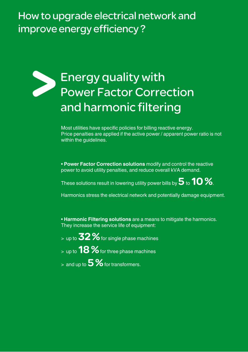
How to upgrade electrical network and improve energy efficiency ?
Energy quality with Power Factor Correction and harmonic filtering
Most utilities have specific policies for billing reactive energy.Price penalties are applied if the active power / apparent power ratio is not within the guidelines.
• Power Factor Correction solutions modify and control the reactive power to avoid utility penalties, and reduce overall kVA demand.
These solutions result in lowering utility power bills by 5 to 10 %.
Harmonics stress the electrical network and potentially damage equipment.
• Harmonic Filtering solutions are a means to mitigate the harmonics. They increase the service life of equipment:
> up to 32 % for single phase machines
> up to 18 % for three phase machines
> and up to 5 % for transformers.

1 monthpayback. We installed a 5Mvar capacitor banks.Annual cost savings will reach €12m & implementation costs €1m.Portucel Paper Mill in Portugal
9%reduction in our energy consumption after we installed 10 capacitor banks.Electricity bill optimized by 8% and payback in 2 yearsTestifies Michelin Automotive in France
¤9mMV Capacitor banks installed, cost saving of €9m, payback in just 2 months.RFF Railways France
1 year70 capacitor banks installed, energy consumption reduced by 10%, electricity bill optimised by 18%, payback in just 1 year.Madrid Barrajas airport Spain
5%LV capacitor bank and active filter installed, energy consumption reduced by 5%.POMA OTIS transportation systems Switzerland
Solutions
Power Factor Correction
Harmonic filtering
Every electric machine needs active and reactive power to operate.Power factor is used to identify the level of reactive energy.If the power factor drops below the limit set by the utility, then power factor correction equipment can be installed in order to avoid penalties.By correcting a poor power factor, these solutions also reduce kVA demand.
Equipment such as drives, inverters, UPS, arc furnaces, transformers during energization and discharge lamps generate harmonic currents and voltage distortion.
The results are a 5 to 10% lower electricity bill, cooler equipment operation and longer equipment life.In addition proper power factor correction helps optimize electrical network loading and improves reliability.
These harmonics stress the network, overload cables and transformers, cause outages and disturb many types of equipment such as computers, telephones, and rotating machines. The life of equipment can be greatly reduced.
DE
9007
0
Before After
1

PE
9008
6
Power Factor Correction
Optimize the size of your electrical installationby increasing the available capacity and reducing the dimensions of your equipment (transformer, cables, etc.).
Reduce your electricity billby reducing your reactive energy consumption.
Improve energy qualityand the service life of your equipment.
Contributeto environmental conservation by reducing losses in transmission and distribution networks.
2

PE
9008
7
Harmonic filtering
Increase continuity of serviceby eliminating risks of stoppages due to nuisance tripping.
Eliminate malfunctionsof your electrical equipment by reducing overheating, increasing its lifetime by up to 30%.
Benefit from the assurance provided by standardization,by anticipating the requirements of regulations currently being prepared, deploying environmentally friendly solutions.
3
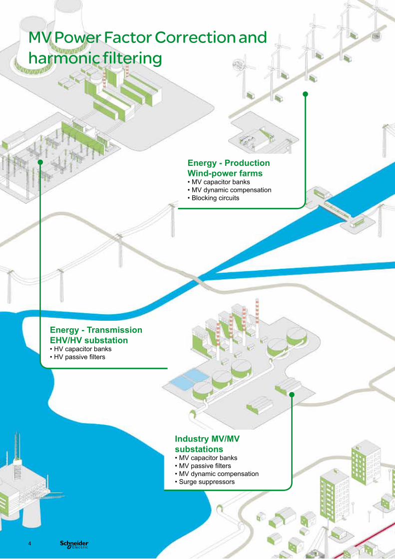
MV Power Factor Correction and harmonic filtering
Energy - Transmission EHV/HV substation• HV capacitor banks• HV passive filters
Industry MV/MV substations• MV capacitor banks• MV passive filters• MV dynamic compensation• Surge suppressors
Energy - Production Wind-power farms• MV capacitor banks• MV dynamic compensation• Blocking circuits
4

Energy - Production Solar power farms• MV dynamic compensation• Blocking circuits
Energy - Distribution MV/MV substation• MV capacitor banks• MV passive filters
Infrastructure MV/LV substation• MV capacitor banks
5

PE
9007
6
PE
9007
8
PE
9007
7
PE
9007
5
PE
9007
9
PE
9008
0
PE
9008
1
MV Power Factor Correction and harmonic filtering
To define the solutions to be employed, you must:• identify and quantify the problems to be solved (usually by an on-site audit);
• analyse the criticality of the installation and validate the objectives to be achieved.
The following table shows the typical solutions proposed for installations in various sectors of activity.
Activity Fixed banks
Automatic banks
Dynamic compensation
Passive filters
Surge suppressors
Blocking circuits
Energy
Transmission ◼ ◼
Distribution ◼ ◼ ◼
Wind-power ◼ ◼ ◼
Solar power ◼ ◼
Infrastructure
Water ◼
Tunnels ◼
Airports ◼
Industry
Paper ◼ ◼
Chemicals ◼ ◼ ◼ ◼
Plastics ◼ ◼ ◼
Glass-ceramics ◼ ◼ ◼
Iron and steel ◼ ◼ ◼ ◼ ◼ ◼
Métallurgy ◼ ◼ ◼ ◼ ◼
Automotive industry ◼ ◼
Cement ◼ ◼ ◼
Mines-quarries ◼ ◼ ◼
Refineries ◼ ◼ ◼ ◼
6

Quality certified:
ISO 9001, ISO 9002 and ISO 14001
Quality & Environment
Schneider Electric undertakes... to reduce the energy bill and CO2 emissions of its customers by proposing products, solutions and services which fit in with all levels of the energy value chain. The power factor correction and harmonic filtering offer form part of the energy efficiency approach.
PE
5673
3
A major strengthIn each of its units, Schneider Electric has an operating organization whose main role is to verify quality and ensure compliance with standards.This procedure is:• uniform for all departments;• recognized by numerous customers and official organizations.But, above all, its strict application has made it possible to obtain the recognition of an independent organization: French QA management organization AFAQ (Association Française pour l’Assurance Qualité).The quality system for design and manufacturing is certified in compliance with the requirements of the ISO 9001 Quality Assurance model.
Stringent, systematic controlsDuring its manufacture, each equipment item undergoes systematic routine tests to verify its quality and compliance:• measurement of operating capacity and tolerances;• measurement of losses;• dielectric testing;• checks on safety and locking systems;• checks on low-voltage components;• verification of compliance with drawings and diagrams.The results obtained are recorded and initialled by the Quality Control Department on the specific test certificate for each device. Up to10%
savings on your energy bill
ISO 14001ISO 9002ISO 900 1
31%
19%
10%
24%
7%5%
2%
1% 1%
Jarylec*
Steel
Zinc
Epoxy resin
Brass
Paper, wood, cardboard
Tin-plated copper
Polypropylene (film)
Aluminium (film)
* Jarylec: dielectric liquid with no PCB or chlorine, compatible with the environment
DE
9009
8
Raw materials breakdown for MV capacitors
7

A comprehensive offerThe power factor correction and harmonic filtering offer form part of a comprehensive offering of products perfectly coordinated to meet all medium- and low-voltage power distribution needs.All these products have been designed to operate together: electrical, mechanical and communications consistency.The electrical installation is accordingly both optimized and more efficient:• improved continuity of service;• losses cut;• guarantee of scalability;• efficient monitoring and management.You thus have all the trumps in hand in terms of expertise and creativity for optimized, reliable, expandable and compliant installations.
A new solution for building your electrical installations
Tools for easier design and setupWith Schneider Electric, you have a complete range of tools that support you in the knowledge and setup of products, all this in compliance with the standards in force and standard engineering practice.These tools, technical notebooks and guides, design aid software, training courses, etc. are regularly updated
Schneider Electric joins forces with your expertise and your creativity for optimized, reliable, expandable and compliant installations.
PE
9008
8
Because each electrical installation is a specific case, there is no universal solution.
The variety of combinations available to you allows you to achieve genuine customization of technical solutions.
You can express your creativity and highlight your expertise in the design, development and operation of an electrical installation.
8

Power Factor Correction and harmonic filtering
Main Contents
MV capacitor banks 11
Protection systems 39
Components 47
Special equipment 61
Installation (drawings, dimensions) 67
Services 71
Selection guide 75
Technical guide 81
9


MV capacitor banksContents
Power Factor Correction and harmonic filtering
Why compensate reactive energy? 12Choice of compensation type 13Choice of compensation location 14Choice of protection system type 15Choice of coupling mode 16Overview of offer 18Functions and general characteristics 20Banks for motor compensation 22Fixed bank CP 214 22Fixed bank CP 214 SAH 24
Banks for industrial compensation 26Automatic bank CP 253 26Automatic bank CP 253 SAH 28
Banks for global compensation 30Fixed bank CP 227 30
Banks for distribution and large site networks 32Automatic bank CP 254 32
Banks for distribution networks 34Fixed bank CP 229 34
Banks for transport and distribution networks 36Fixed bank CP 230 36
11

MV capacitor banks Why compensate reactive energy?
Every electrical system (cable, line, transformer, motor, lighting, etc.) employs two forms of energy:• Active energy consumed (kWh). This is fully transformed into mechanical, thermal or luminous power. It corresponds to the active power P (kW) of the loads. This is the “useful” energy.• Reactive energy consumed (kvarh). It serves to magnetize motors and transformers. It corresponds to the reactive power Q (kvar) of the loads.It results in a phase difference (ϕ) between the voltage and current. This is an energy that is “necessary” but produces no work.
The reactive energy demanded by the loads is supplied by the electrical network. This energy must be supplied in addition to the active energy. This flow of reactive energy over the electrical networks results, due to a larger current demand, in:• additional voltage drops;• transformer overloading;• overheating in circuits... and hence losses.
For these reasons, it is necessary to produce reactive energy as close as possible to the loads, to avoid demand for it on the network, thereby increasing the installation’s efficiency! This is what is called "reactive energy compensation" or "power factor correction". The easiest and commonest way of generating reactive energy is to install capacitors on the network.
Compensating reactive energy makes it possible to
increase the capacity of the installation (transformers, cables) by reducing the load;
reduce losses by Joule effect;
reduce voltage drops;
increase the installation’s service life by reducing overheating;
reduce the electricity bill.
Powergeneration
Transmissionnetwork Motor
Active energy Active energy
Reactive energy Reactive energy
Powergeneration
Transmissionnetwork Motor
Active energy Active energy
Reactive energy
Capacitors
DE
9007
1D
E90
071
12

Choice of compensation typeMV capacitor banks
A “capacitor bank” generally consists of several single-phase or three-phase capacitor units assembled and interconnected to produce very powerful systems.
The capacitor banks are branch-mounted on the network. They may be of fixed or automatic type.
Fixed bankThe entire bank is put into operation, with a fixed value of kvar.This is “on/off” type operation.This type of compensation is used:• when their reactive power is low (15% of the power of the upstream transformer) and the load is relatively stable;• on HV and EHV transmission networks for power values of up to 100 Mvar.
Automatic bankThe bank is divided up into “steps” with capability for switching on or off a smaller or larger number of steps automatically. This is a permanent adjustment to the reactive power demand, due to load fluctuations.This type of bank is very commonly used by certain heavy industries (high installed capacity) and energy distributors in source substations. It allows step-by-step regulation of reactive energy. Each step is operated by a switch or contactor.Capacitor step switching on or off can be controlled by power factor controllers. For this purpose, the network current and voltage information must be available upstream of the banks and loads.
Choice of bank type according to the harmonics The presence of nonlinear loads (variable speed drives, inverters, etc.) creates harmonic currents and voltages. The compensation equipment will be chosen according to the magnitude of these harmonics:• Either the installation has no significant harmonics and there is no risk of resonance. In this case a bank appropriate for networks with a low harmonic level (standard type) is chosen.• Or the installation has a significant level of harmonics and/or there is a risk of resonance. In such cases a bank provided with a detuning reactor, appropriate for networks with a high harmonic level, is chosen.
13

MV capacitor banks Choice of compensation location
Individual Individual compensation is recommended especially when a load of power greater than 300 kW is present, and if it remains energized during most working hours. This is especially the case of motors driving machines with great inertia: centrifuges, compressors and fans, for example.Operation of the switch specific to the load in this case automatically causes capacitor switching on or off. The production of reactive energy takes place directly at the place where it is consumed.
For the whole length of the power cable this results in a reduction in the reactive current load. Individual compensation therefore makes a major contribution to the reduction in apparent power, losses and voltage drops in conductors.
Partial/by sectorIn the case of compensation by sector (or workshop), several loads are connected to a joint capacitor bank which is operated by its own switchgear. In large installations, the bank compensates all the reactive energy consumers in a workshop or a sector.This form of compensation is recommended for installations where a number of loads are put into operation simultaneously and in a manner virtually reproducible over time.
Partial compensation has the advantage of entailing lower capital investment costs than individual compensation. This is because calculation of the power of a permanently installed capacitor bank takes into account expansion of the sector load. However, the load curves must be well known beforehand in order to correctly size the capacitor banks and avoid risks of over-compensation (reactive power supplied exceeding the demand). Over-compensation generally results in the local occurrence of permanent overvoltages which cause premature electrical equipment ageing.
GlobalIn the case of global compensation, the production of reactive energy is grouped in a single place, usually in the transformer substation. However, it is not necessary for the capacitors to be installed precisely at the metering level. On the contrary, it is recommended to install the capacitors in an appropriate location which takes into account various constraints such as space requirements.
The capacitors have a good duty factor; the layout is clear; supervision of the installation and its various parts is easier than in the case of compensation by sector. Finally, if stepped automatic adjustment is adopted, there will in this case be good follow-up of the plant’s load curve, which avoids operations by personnel (manual switching on/off).This solution is economically worthwhile if the load variations are not attributable to specific loads.
Individual compensation
DE
9007
2
Partial compensation / by sector
DE
9007
2
Total compensation
DE
9007
2
14

Choice of protection system typeMV capacitor banks
Internal fusesEach capacitance element of the capacitor is protected by a fuse. Any fault in this element will result in fuse blowing. The defective element will thus be eliminated. The result will be a slight capacitance variation and the voltage will be distributed over the sound elements in series.
Protection by internal fuses increases the availability of capacitor banks, because the loss of one element no longer systematically results in tripping of the bank (see details in Propivar NG technical description).
Unbalance protectionThe bank is divided into two star connections (see diagram on page 16). When there is a capacitance unbalance (variation in capacitance of a capacitor), a current flowing between the 2 neutrals appears. This current is detected by a current transformer and an unbalance relay.
This differential arrangement is a sensitive protection system, independent of network interference, very suitable whatever the power values.
PE
9008
9
15
MV capacitor banks Choice of coupling mode
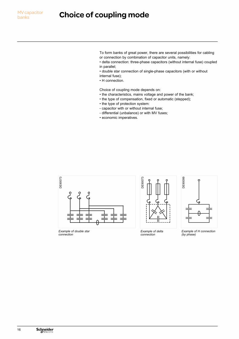
To form banks of great power, there are several possibilities for cabling or connection by combination of capacitor units, namely:• delta connection: three-phase capacitors (without internal fuse) coupled in parallel;• double star connection of single-phase capacitors (with or without internal fuse);• H connection.
Choice of coupling mode depends on:• the characteristics, mains voltage and power of the bank;• the type of compensation, fixed or automatic (stepped);• the type of protection system:- capacitor with or without internal fuse;- differential (unbalance) or with MV fuses;• economic imperatives.
Example of delta connection
Example of double star connection
Example of H connection (by phase)
DE
9007
3
DE
9007
3
DE
9009
9
16

Q (kvar) / 600 900 1 200 2 000 2 400 3 000 3 500 4 000 6 000 U network (kV) 3,3 4,165,56,6101113,213,81520223033
Recommended configuration
YY connection6 single-phase
capacitors
YY connection of 12 single-phase capacitors (series)
Delta connection1 or 2 three-phase
capacitors
YY connection9 or 12 capacitors
PE
9009
0
PE
9009
1
17

MV capacitor banks Overview of offer
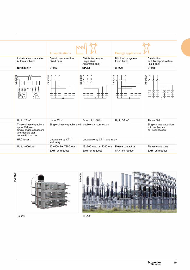
Industrial application All applications Energy application
Applications Motor compensation Industrial compensation Industrial compensation Global compensation Distribution system Distribution system Distribution Fixed bank Automatic bank Automatic bank Fixed bank Large sites Fixed bank and Transport system Automatic bank Fixed bankReferences CP214 CP214SAH* CP253 CP253SAH* CP227 CP254 CP229 CP230Three-lines diagrams
Maximum voltage Up to 12 kV Up to 12kV Up to 12 kV Up to 36kV From 12 to 36 kV Up to 36 kV Above 36 kVConnection mode Three-phase capacitors with delta connection Three-phase capacitors Three-phase capacitors Single-phase capacitors with double star connection Single-phase capacitors up to 900 kvar, up to 900 kvar, with double star single-phase capacitors single-phase capacitors or H connection with double star with double star connection above connection above Type of protection HRC fuses (**) HRC fuses HRC fuses Unbalance by CT*** Unbalance by CT*** and relay and relay Maximum power**** 2 x 450, i.e. 900 kvar Up to 4500 kvar Up to 4000 kvar 12 x 600, i.e. 7200 kvar 12 x 600 kvar, i.e. 7200 kvar Please contact us Please contact usComments SAH* on request SAH* on request SAH* on request SAH* on request
* SAH: Detuning Reactor** HRC: High Rupturing Capacity*** CT: Current Transformer**** For larger power rating, please contact us
CP 214 CP 227SAH CP 253 CP 254
PE
9010
7
PB
1019
96_S
E
PB
1020
03_S
E
PB
1020
01_S
E
DE
9008
2
DE
9008
2
DE
9008
2
18
Industrial application All applications Energy application
Applications Motor compensation Industrial compensation Industrial compensation Global compensation Distribution system Distribution system Distribution Fixed bank Automatic bank Automatic bank Fixed bank Large sites Fixed bank and Transport system Automatic bank Fixed bankReferences CP214 CP214SAH* CP253 CP253SAH* CP227 CP254 CP229 CP230Three-lines diagrams
Maximum voltage Up to 12 kV Up to 12kV Up to 12 kV Up to 36kV From 12 to 36 kV Up to 36 kV Above 36 kVConnection mode Three-phase capacitors with delta connection Three-phase capacitors Three-phase capacitors Single-phase capacitors with double star connection Single-phase capacitors up to 900 kvar, up to 900 kvar, with double star single-phase capacitors single-phase capacitors or H connection with double star with double star connection above connection above Type of protection HRC fuses (**) HRC fuses HRC fuses Unbalance by CT*** Unbalance by CT*** and relay and relay Maximum power**** 2 x 450, i.e. 900 kvar Up to 4500 kvar Up to 4000 kvar 12 x 600, i.e. 7200 kvar 12 x 600 kvar, i.e. 7200 kvar Please contact us Please contact usComments SAH* on request SAH* on request SAH* on request SAH* on request
CP 229 CP 230
PE
9010
8
PE
9008
4
DE
9008
2
DE
9008
2
DE
9008
2
DE
9008
2
DE
9008
2
19

MV capacitor banks Functions and general characteristics
* Standard offer; for other values, please contact us◼: standard v: optional functions
CP 214 CP 253 CP 227 CP 254 CP 229 CP 230Mains voltage ≤ 7.2 kV ◼ ◼ ◼ ◼ ◼ ≤ 12 kV ◼ ◼ ◼ ◼ ◼ ≤ 24 kV ◼ ◼ ◼ ≤ 36 kV ◼ ◼ ◼ ◼ ≥ 52 kV ◼Compensation and FilteringBank power* kvar 900 4 500 7 200 7 200Steps quantity 1 5* 1 5* 1 1 type fixed auto fixed auto fixed fixedCapacitor connection delta ◼ ◼ double star v ◼ ◼ ◼ ◼ H v vDetuning reactor v v v v v vCapacitor protectionInrush reactors (N/A with DR) ◼ ◼ ◼ ◼ ◼ ◼Fuse protection ◼ ◼Blown fuse indicator v vUnbalance protection v ◼ ◼ ◼ ◼Quick discharge reactor (< 24 kV) v v v v v Switch SF6 v vVacuum interrupter v v MeasuringCurrent transformer v vVoltage transformer v vPeople safetyEarthing switch 3-pole v v 5-pole vLine disconnector v v with earthing switch v vInterlock v vArc fault detector v v v Control and regulationControl and mounted on door v vmonitoring unit separated ◼ ◼Automatic controller standard ◼ ◼ communication v vAuto/local selector switch v vIngress protectionIP IP00 ◼ ◼ IP23 ◼ ◼ ◼ ◼ IP54 v v v vDouble roof v v v vConnectionCable entry bottom ◼ ◼ ◼ ◼ ◼ ◼ top v v v v v vAccess with door v v v v
20

Service conditionsAmbient air temperature• ≤ 40°C.• ≤ 30 °C average per 24h.• ≥ -25°C.
Altitude• ≤ 1000m.
AtmosphereClean industrial air (no dust, fumes, gases or corrosive or flammable vapours, and no salt).
HumidityMean relative humidity value over 24h < 95%.
Special service conditions (please, consult us)
Schneider Electric develops solutions to meet the following special conditions:• Temperature from -40°C to +50°C (derating, ventilation).• Corrosive atmospheres, vibrations (adaptations where applicable).• Altitude > 1000 m (derating).
Storage conditionsTo conserve all the qualities of the functional unit in the event of extended storage, we recommend storing the equipment in its original packaging, in a dry location, sheltered from rain and sun and at a temperature ranging between -25°C and +55°C.
StandardsThe equipment proposed in this offer has been designed, manufactured and tested in accordance with the requirements of the following standards and recommendations:• High-voltage capacitors: CEI 60871-1&2, BS 1650, VDE 0560, C22-2 N°190-M1985, NEMA CP1.• High-voltage circuit breakers: IEC 56.• Current transformers: IEC 60044.• Earthing switch: IEC 129C.• Relays, Power factor controller: IEC 60010.• Quick discharge reactors, Damping reactors: IEC 60076-6.• Insulators: IEC 168 - 273 - 815.• High-voltage contactors: IEC 420 / IEC 470.• High-voltage fuses: IEC 282.1 / IEC 787.
Common electrical characteristics• Tolerance on bank power rating: 0/+10% (0/+5%, power > 3 Mvar).• Relative capacitance variation with temperature: -3,5.10-4/°C
Insulation coordination
Highest voltage for the equipment Power-frequency withstand Impulse withstandUM (kV) voltage (kV rms, 50 Hz - 1 mn) voltage (kV peak, 1.2 / 50 μs)7.2 20 6012 28 7517.5 38 9524 50 12536 70 170
21
MV capacitor banks Banks for motor compensation
Insulation up to 12 kV – 50 Hz / 60 Hz Fixed bank CP214
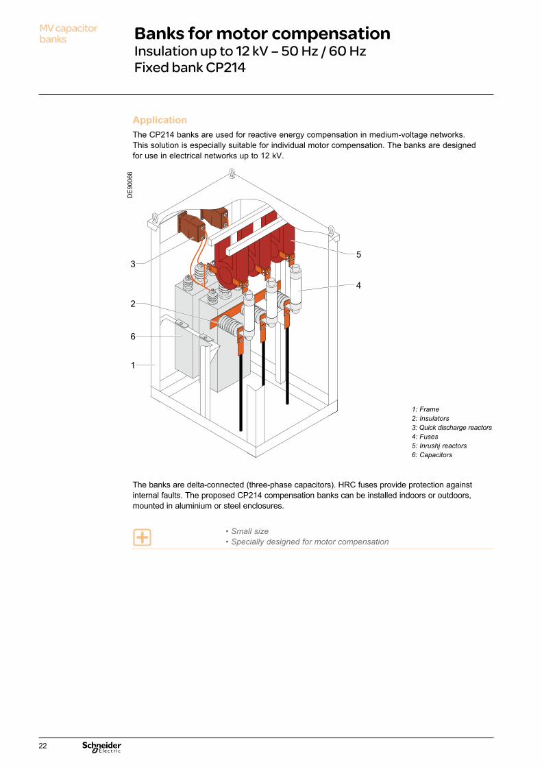
ApplicationThe CP214 banks are used for reactive energy compensation in medium-voltage networks. This solution is especially suitable for individual motor compensation. The banks are designed for use in electrical networks up to 12 kV.
The banks are delta-connected (three-phase capacitors). HRC fuses provide protection against internal faults. The proposed CP214 compensation banks can be installed indoors or outdoors, mounted in aluminium or steel enclosures.
• Small size• Specially designed for motor compensation
4
2
53
1
6
Références Description
3 TP de décharge rapide / Discharge Coil
4 Fusible / Fuse HRC
5 Self de choc / Damping Reactor
6 Condensateurs / Capacitor Units
1 Châssis / Frame
2 Isolateur / Insulator
1: Frame2: Insulators3: Quick discharge reactors4: Fuses5: Inrushj reactors6: Capacitors
DE
9006
6
22
Electrical characteristicsD
B40
6316
Pow
er (k
var)
Mains voltage (kV)
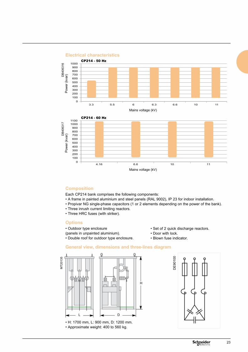
CP214 - 50 Hz
CP214 - 60 Hz
DB
4063
17
Mains voltage (kV)
Pow
er (k
var)
CompositionEach CP214 bank comprises the following components:• A frame in painted aluminium and steel panels (RAL 9002), IP 23 for indoor installation.• Propivar NG single-phase capacitors (1 or 2 elements depending on the power of the bank).• Three inrush current limiting reactors.• Three HRC fuses (with striker).
Options• Outdoor type enclosure (panels in unpainted aluminium).• Double roof for outdoor type enclosure.
General view, dimensions and three-lines diagram
• H: 1700 mm, L: 900 mm, D: 1200 mm.• Approximate weight: 400 to 560 kg.
L D
H
MT2
0135
DE
9010
0
• Set of 2 quick discharge reactors.• Door with lock.• Blown fuse indicator.
23
MV capacitor banks Banks for motor compensation
Insulation up to 12 kV – 50 Hz / 60 Hz Fixed bank CP214 SAH
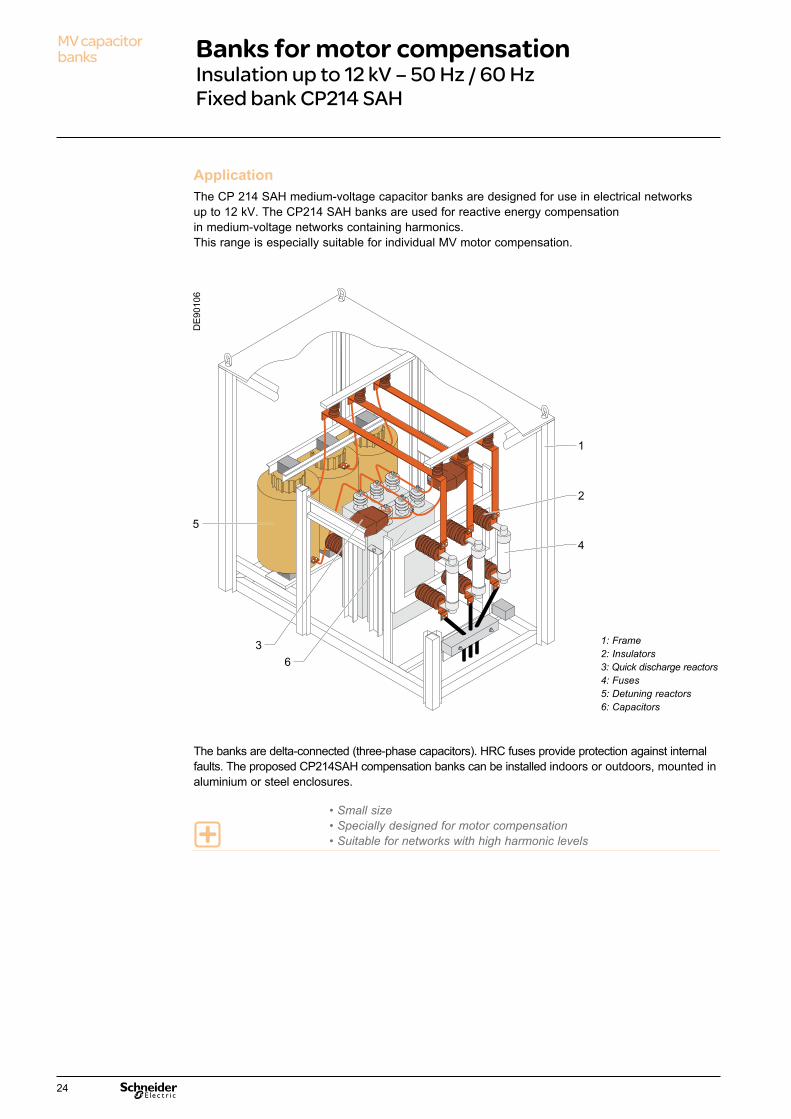
ApplicationThe CP 214 SAH medium-voltage capacitor banks are designed for use in electrical networks up to 12 kV. The CP214 SAH banks are used for reactive energy compensation in medium-voltage networks containing harmonics.This range is especially suitable for individual MV motor compensation.
The banks are delta-connected (three-phase capacitors). HRC fuses provide protection against internal faults. The proposed CP214SAH compensation banks can be installed indoors or outdoors, mounted in aluminium or steel enclosures.
• Small size• Specially designed for motor compensation• Suitable for networks with high harmonic levels
5
4
1
2
6
Références Description
3 TP de décharge rapide / Discharge Coil
4 Fusible / Fuse HRC
5 Self anti-harmoniques / Detuned Reactor
6 Condensateurs / Capacitor Units
1 Châssis / Frame
2 Isolateur / Insulator
3 1: Frame2: Insulators3: Quick discharge reactors4: Fuses5: Detuning reactors6: Capacitors
DE
9010
6
24

L D
H
80
DE
9006
2
Electrical characteristics
CompositionEach CP214SAH bank comprises the following elements:• A frame in painted aluminium and steel panels (RAL 9002), IP 23 for indoor installation.• Propivar NG single-phase capacitors (1 or 2 elements depending on the power of the bank).• Three HRC fuses (with striker).• A three-phase detuning reactor (dry type with magnetic core and natural convection cooling).
Options• Outdoor type enclosure (panels in unpainted aluminium).• Blown fuse indicator.• Sets of two quick discharge reactors: 7.2 - 12 kV.• Door with lock.• Double roof for outdoor type.
General view, dimensions and three-lines diagram
• H: 1900 mm, L: 2000 mm, D: 1100 mm.• Approximate weight: 600 to 1000 kg.
DE
9010
0b
DB
4063
34P
ower
(kva
r)
Mains voltage (kV)
DB
4063
35
Mains voltage (kV)
Pow
er (k
var)
25

MV capacitor banks Banks for industrial compensation
Insulation up to 12 kV – 50 Hz / 60 Hz Automatic bank CP253
ApplicationThe CP253 medium-voltage capacitor banks are designed for use in electrical networks up to 12 kV. They are used for total installation compensation, when the load level is fluctuating.The “1 step” CP253 model is mainly designed for individual compensation of MV motors to avoid the risk of self-excitation.
These banks are delta-connected (three-phase capacitors) and the HRC fuses provide protection against internal faults. An optional cubicle containing a power factor controller can be used to control the steps, thus forming an automatic compensation bank. For steps power values greater than 900 kvar, single-phase capacitors connected in double star will be used (maximum of 12 capacitors, maximum power 4500 kvar).
• Total installation compensation• Fluctuating load level• Ease of access to components• Simplified maintenance• Easy installation
2
1
6
4
Références Description
3 TP de décharge rapide / Discharge Coil
4 Fusible / Fuse HRC
5 Contacteurs / Contactor
6 Condensateurs / Capacitor Units
1 Châssis / Frame
2 Isolateur / Insulator
5
7
7 Self de choc / Damping Reactor
3
1: Frame2: Insulators3: Quick discharge reactors4: Fuses5: Contactors6: Capacitors7: Inrush reactors
DE
9010
7
26
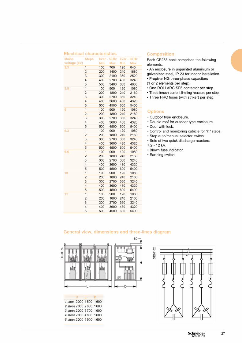
Options• Outdoor type enclosure.• Double roof for outdoor type enclosure.• Door with lock.• Control and monitoring cubicle for "n" steps.• Step auto/manual selector switch.• Sets of two quick discharge reactors: 7.2 - 12 kV.• Blown fuse indicator.• Earthing switch.
CompositionEach CP253 bank comprises the following elements:• An enclosure in unpainted aluminium or galvanized steel, IP 23 for indoor installation.• Propivar NG three-phase capacitors (1 or 2 elements per step).• One ROLLARC SF6 contactor per step.• Three inrush current limiting reactors per step.• Three HRC fuses (with striker) per step.
L D
H
80
DE
9007
4
H L D1 step 2 000 1 500 1 6002 steps 2 000 2 600 1 6003 steps 2 000 3 700 1 6004 steps 2 000 4 800 1 600 5 steps 2 000 5 900 1 600
DE
9010
2
Electrical characteristics
General view, dimensions and three-lines diagram
Mains voltage (kV)
Steps kvar - 50 Hz kvar - 60 HzMin. Max. Min. Max.
3.3 1 100 700 120 8402 200 1400 240 16803 300 2100 360 25204 400 2700 480 32405 500 3400 600 4080
5.5 1 100 900 120 10802 200 1800 240 21603 300 2700 360 32404 400 3600 480 43205 500 4500 600 5400
6 1 100 900 120 10802 200 1800 240 21603 300 2700 360 32404 400 3600 480 43205 500 4500 600 5400
6.3 1 100 900 120 10802 200 1800 240 21603 300 2700 360 32404 400 3600 480 43205 500 4500 600 5400
6.6 1 100 900 120 10802 200 1800 240 21603 300 2700 360 32404 400 3600 480 43205 500 4500 600 5400
10 1 100 900 120 10802 200 1800 240 21603 300 2700 360 32404 400 3600 480 43205 500 4500 600 5400
11 1 100 900 120 10802 200 1800 240 21603 300 2700 360 32404 400 3600 480 43205 500 4500 600 5400
27

MV capacitor banks Banks for industrial compensation
Insulation up to 12 kV – 50 Hz / 60 HzAutomatic bank CP253 SAH
ApplicationThe CP253 SAH medium-voltage capacitor banks are designed for use in electrical networks up to 12 kV. The CP253 SAH banks are used for automatic reactive energy compensation in medium-voltage networks with a high harmonic level. This solution is particularly suitable for total installation compensation where the load level is fluctuating.
These banks are delta-connected (three-phase capacitors) and the HRC fuses provide protection against internal faults. An optional cubicle containing a power factor controller can be used to control the steps, thus forming an automatic compensation bank. For steps power values greater than 900 kvar, single-phase capacitors connected in double star will be used (maximum of 12 capacitors, maximum power 4500 kvar).
• Total installation compensation• Fluctuating load level• Ease of access to components• Simplified maintenance• Easy installation• Suitable for networks with a high harmonic level
1
Références Description
3 Fusible / Fuse HRC
4 Contacteurs / Contactor
5 Condensateurs / Capacitor Units
1 Châssis / Frame
2 Isolateur / Insulator
6 Self anti-harmoniques / Detuned Reactor
2
3
4
5
6
1: Frame2: Insulators3: Fuses4: Contactors5: Capacitors6: Detuning reactors
DE
9010
8
28

L D
H
80
DE
9007
5
H L D1 step 2 000 1 500 2 4002 steps 2 000 2 600 2 4003 steps 2 000 3 700 2 4004 steps 2 000 4 800 2 400 5 steps 2 000 5 900 2 400
DE
9010
2b
Options• Outdoor type enclosure.• Double roof for outdoor type enclosure.• Door with lock.• Control and monitoring cubicle for «n» steps.• Step auto/manual selector switch.• Sets of two quick discharge reactors: 7.2 - 12 kV.• Blown fuse indicator.• Earthing switch.
CompositionEach CP253SAH bank comprises the following elements:• An enclosure in unpainted aluminium or galvanized steel, IP 23 for indoor installation.• Propivar NG three-phase capacitors (1 or 2 elements per step).• One ROLLARC SF6 contactor per step.• A detuning reactor (dry type, with magnetic core, air cooling) per step.• Three HRC fuses (with striker) per step.
Electrical characteristics
General view, dimensions and three-lines diagram
Mains voltage (kV)
Steps kvar - 50 Hz kvar - 60 HzMin. Max. Min. Max.
3.3 1 100 700 120 8802 200 1450 240 17503 300 2200 360 26504 400 2800 480 35005 500 3400 600 3400
5.5 1 100 950 120 11502 200 1900 240 22503 300 2800 360 34004 400 3800 480 45365 500 4700 600 5700
6 1 100 950 120 11502 200 1900 240 22503 300 2800 360 34004 400 3800 480 45365 500 4700 600 5700
6.3 1 100 950 120 11502 200 1900 240 22503 300 2800 360 34004 400 3800 480 45365 500 4700 600 5700
6.6 1 100 950 120 11502 200 1900 240 22503 300 2800 360 34004 400 3800 480 45365 500 4700 600 5700
10 1 100 950 120 11502 200 1900 240 22503 300 2800 360 34004 400 3800 480 45365 500 4700 600 5700
11 1 100 950 120 11502 200 1900 240 22503 300 2800 360 34004 400 3800 480 45365 500 4700 600 5700
29

MV capacitor banks Banks for global compensation
Insulation up to 36 kV – 50 Hz / 60 HzFixed bank CP227
ApplicationThe CP227 medium-voltage capacitor banks are designed for use in electrical networks up to 36 kV. This range is mainly used for total installation compensation.
These banks are connected in double star and the unbalance current detection system provides protection against internal faults. The proposed CP227 compensation banks can be installed outdoors or indoors, mounted in aluminium or steel enclosures.NB: CP 227 SAH fixed banks with detuning reactor are designed and proposed on request.
• Total installation compensation• Ease of access to components• Simplified maintenance• Easy installation
2
4
3
1
Références Description
1
2
3
4
5
5
TP de décharge rapide / Discharge Coil
Châssis / Frame
TC de déséquilibre / Unbalance CT
Self de choc / Damping Reactor
Condensateurs / Capacitor Units
1: Frame2: Quick discharge reactors3: Unbalance CT 4: Inrush reactors5: Capacitors
DE
9006
7
30
L D
80
DE
9006
4
Electrical characteristics
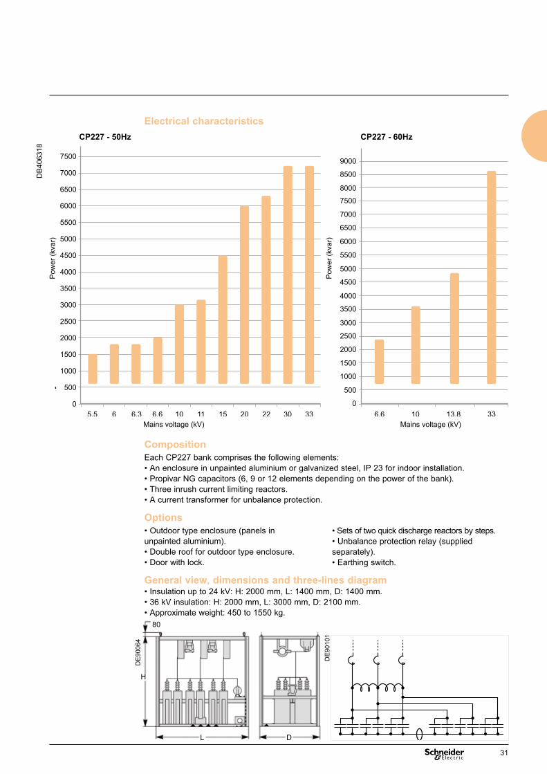
CompositionEach CP227 bank comprises the following elements:• An enclosure in unpainted aluminium or galvanized steel, IP 23 for indoor installation.• Propivar NG capacitors (6, 9 or 12 elements depending on the power of the bank).• Three inrush current limiting reactors.• A current transformer for unbalance protection.
Options• Outdoor type enclosure (panels in unpainted aluminium).• Double roof for outdoor type enclosure.• Door with lock.
General view, dimensions and three-lines diagram
DB
4063
18
Pow
er (k
var)
Pow
er (k
var)
Mains voltage (kV) Mains voltage (kV)
• Insulation up to 24 kV: H: 2000 mm, L: 1400 mm, D: 1400 mm.• 36 kV insulation: H: 2000 mm, L: 3000 mm, D: 2100 mm.• Approximate weight: 450 to 1550 kg.
H
DE
9010
1
• Sets of two quick discharge reactors by steps.• Unbalance protection relay (supplied separately).• Earthing switch.
31
MV capacitor banks Banks for distribution
and large sites networksInsulation up to 36 kV – 50 Hz / 60 HzAutomatic bank CP254
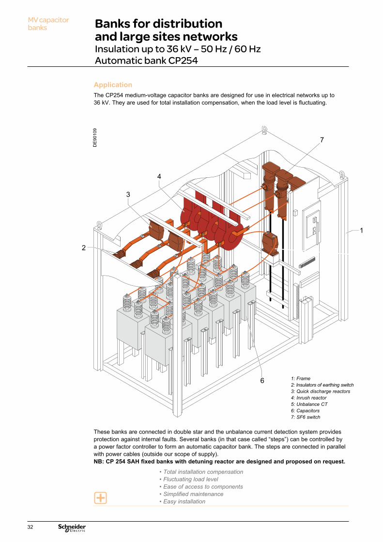
ApplicationThe CP254 medium-voltage capacitor banks are designed for use in electrical networks up to 36 kV. They are used for total installation compensation, when the load level is fluctuating.
These banks are connected in double star and the unbalance current detection system provides protection against internal faults. Several banks (in that case called “steps”) can be controlled by a power factor controller to form an automatic capacitor bank. The steps are connected in parallel with power cables (outside our scope of supply).NB: CP 254 SAH fixed banks with detuning reactor are designed and proposed on request.
• Total installation compensation• Fluctuating load level• Ease of access to components• Simplified maintenance• Easy installation
4
6
3
1
2
7
Références Description
3 TP de décharge rapide / Discharge Coil
4
5
6 Condensateurs / Capacitor Units
1 Châssis / Frame
2 Isolateur / Insulator
Self anti-harmoniques / Detuned Reactor
TC de déséquilibre / Unbalance CT
1: Frame2: Insulators of earthing switch3: Quick discharge reactors4: Inrush reactor5: Unbalance CT6: Capacitors7: SF6 switch
DE
9010
9
32

Options• Outdoor type enclosure.• Double roof for outdoor type enclosure.• Door with lock.• Unbalance protection relay (supplied separately)*.• Three-pole / Five-pole earthing switch.• Ligne Current Transformer.• Voltage Transformer.• Sets of two quick discharge reactors.• Control and monitoring cubicle for «n» steps.• Step auto/manual selector switch.* 2 relays are used for banks having capacitors with internal fuses; a single relay is required when there are no internal fuses. If the monitoring and protection cubicle option is selected, the relays are installed in the cubicle.
General view, dimensions and three-lines diagram
CompositionEach CP254 bank comprises the following elements:• An enclosure in unpainted aluminium or galvanized steel, IP 23 for indoor installation.• Propivar NG capacitors (6, 9 or 12 elements per step depending on the power of the bank).• An SF6 switch.• Three inrush current limiting reactors.• A current transformer for unbalance protection.
• Insulation up to 24 kVH: 2000 mm, L: 2600 mm, D: 1400 mm.• 36 kV insulationH: 2100 mm, L: 3000 mm, D: 2100 mm.• Approximate weight: 450 to 1550 kg.
L D
H
80
DE
9007
6
DE
9010
3
Mains voltage (kV) kvar - 50 Hz kvar - 60 HzMin. Max. Min. Max.
13.8 - - 720 480015 300 4500 - -20 300 6000 - -22 300 6300 - -30 600 7200 - -33 600 7200 720 8640
Electrical characteristics
33

MV capacitor banks Banks for distribution networks
Insulation up to 36 kV – 50 Hz / 60 HzFixed bank CP229
ApplicationThe banks of the CP229 range are mounted in aluminium racks.They are used for reactive energy compensation in medium-voltage networks. This high power range is designed for total compensation of large industrial plants and power distribution systems.
These banks are connected in double star (up to 36 capacitors) and the unbalance current detection system provides protection against internal faults.NB: CP 229 SAH fixed banks with detuning reactor are designed and proposed on request.
• Total plant compensation• Suitable for high power• Ease of access to components• Simplified maintenance• Easy installation
1
2
4
7
6
5
3
Références Description
1
2
3
4
5
6
Condensateurs / Capacitor Units
Isolateur / Insulator
Châssis / Frame aluminium
Jeu de barre CUIVRE / COPPER busbar
Pieds support / Base support aluminium
TC de déséquilibre / Unbalance CT
7 Plage de raccordement / Available connexion
1: Frame2: Insulators3: Unbalance CT4: Supporting stands5: Capacitors6: Copper busbar7: Connection pad
DE
9006
8
34
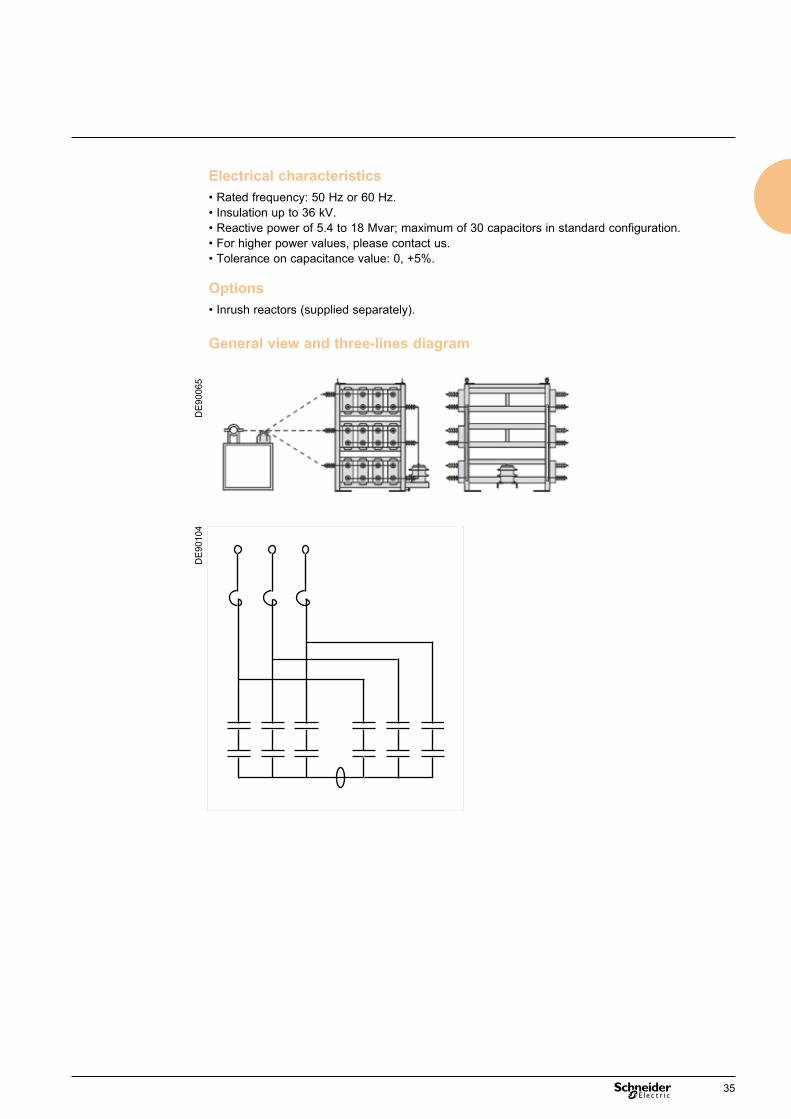
Electrical characteristics• Rated frequency: 50 Hz or 60 Hz.• Insulation up to 36 kV.• Reactive power of 5.4 to 18 Mvar; maximum of 30 capacitors in standard configuration.• For higher power values, please contact us.• Tolerance on capacitance value: 0, +5%.
Options• Inrush reactors (supplied separately).
General view and three-lines diagram
DE
9006
5D
E90
104
35
MV capacitor banks Banks for transport and distribution
networksInsulation up to 245 kV – 50 Hz / 60 HzFixed bank CP230
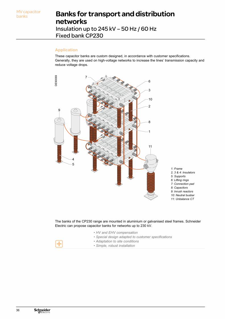
ApplicationThese capacitor banks are custom designed, in accordance with customer specifications. Generally, they are used on high-voltage networks to increase the lines’ transmission capacity and reduce voltage drops.
The banks of the CP230 range are mounted in aluminium or galvanised steel frames. Schneider Electric can propose capacitor banks for networks up to 230 kV.
• HV and EHV compensation• Special design adapted to customer specifications• Adaptation to site conditions• Simple, robust installation
Références Description
1
2
3
4
5
7
8
9
10
11
6
Condensateurs / Capacitor Units
Isolateur / Insulator
Châssis / Frame aluminium
Jeu de barre neutre / neutral busbar
TC de déséquilibre / Unbalance CT
Isolateur / Insulator
Support / Support
Isolateur / Insulator
Anneaux de levage / Lifting eyes
Plage de raccordement / Terminal pads
Self de choc / Damping Reactor
9
4
5
7
6
3
10
2
1
8
11
1: Frame2, 3 & 4: Insulators5: Supports6: Lifting rings7: Connection pad8: Capacitors9: Inrush reactors10: Neutral busbar11: Unbalance CT
DE
9006
9
36

Electrical characteristics• Rated frequency: 50 Hz or 60 Hz.• Insulation: up to 245 kV.• Maximum reactive power: 100 Mvar, for higher values, please contact us.• Tolerance on capacitance value: 0, +5%.• Inrush current limiting reactors: single-phase reactors, dry type air core.
General view and three-lines diagram
DE
9007
7D
E90
105
37
Protection systemsContents
Power Factor Correction and harmonic filtering
Types of faults in capacitor banks 40People safety 41Protection of capacitors 42Arc fault detector 44
39

Protection systems Types of faults in capacitor banks
Element short circuit in a capacitor Without internal protection (Fig. 1) Elements wired in parallel are therefore bypassed by the short circuited unit (cf. Propivar NG capacitors, p.46).• The capacitor’s impedance is modified.• The voltage applied is distributed over one set less in series.• Each set is therefore subjected to a higher voltage stress, which may cause other element failures in cascade until complete short circuit. Initial voltage of element, UNE (equal to UN/4) becomes, after fault, equal to UN/3, either 1.33 UNE.
With internal protection (Fig. 2)Blowing of the internal fuse linked in series eliminates the short circuited element.• The capacitor stays in service.• Its impedance is "slightly" modified accordingly.
Overload Overload is due to a permanent or temporary overcurrent:• permanent overcurrent due to:- a rise in the supply voltage;- the circulation of a harmonic current due to the presence of nonlinear loads such as static converters (rectifiers, variable speed drives), arc furnaces, etc.;• temporary overcurrent due to energizing of steps of a bank.An overload results in overheating which is harmful to dielectric strength, and causes premature capacitor ageing.
Short circuit (two- and three-phase) The short circuit is an internal or external fault between live conductors, either phase-to-phase (delta-connected capacitors), or phase-to-neutral (star-connected capacitors). External short circuits may be due to external overvoltages (lightning stroke, switching surge) or insulation faults (foreign bodies modifying clearances).They result in electric arcs causing material peeling, overpressures and electrodynamic forces. Internal short circuits result in electric arcs in the oil, which causes the appearance of gas in the sealed enclosure leading to violent overpressures which can cause rupture of the enclosure and leakage of the dielectric.
Phase-to-earth fault The earth fault consists either of an internal fault between a live part of the capacitor and the frame consisting of the metal enclosure which is earthed (for protection of human life), or an external fault between live conductors and the frame.The effects of the short circuit depend on the sum of the fault impedance and the loop impedance (which depends on the network’s earthing system). The resulting current may be very low and inadequate to cause blowing of external fuses, which may result in a gradual overpressure (accumulation of gases) and heavy stresses on the enclosure.
The main faults that can affect a capacitor bank are:• Element short circuit in a capacitor.• Overload.• Short circuit (two- and three-phase).• Phase-to-earth fault.
Figure 1: Wafer short circuit without internal fuse protection
1.33 IN
If=1.33 IN
1.33 UNE
1.33 UNE
1.33 UNE
Figure 2: Wafer short circuit with internal fuse protection
0.978 UNE
0.978 UNE
0.978 UNE
1.067 UNE
0.978 IN
DE
9005
6D
E90
057
40

People safetyProtection systems
Digital protection relays It performs protection against the various types of fault.• Phase-to-earth fault by earth overcurrent protection (ANSI 50N-51N) which allows detection of overcurrents due to phase-to-earth faults. It uses measurement of the fundamental component of the earth current.• Overload by thermal overload protection (ANSI 49 RMS) which can protect capacitors against overloads based on measurement of current drawn.• Short circuit by phase overcurrent protection (ANSI 50-51) which allows detection of overcurrents due to phase-to-phase faults. It uses measurement of the fundamental component of the currents coming from 2 or 3 “phase CT” current transformers.
Quick discharge reactorThe installation of two quick discharge reactors (“PT” potential transformers) between phases of the bank allows capacitor discharge time to be reduced from 10 minutes to about 10 seconds.This reduction in discharge time provides:• safety for personnel during any servicing operations;• a reduction in waiting time prior to earthing (closing of the earthing switch).No more than 3 consecutive discharges are acceptable and it is essential to comply with a 2-hour rest period (for cooling) before starting a sequence again.
Earthing switchThis is a safety-critical component, designed to ground and discharge capacitors prior to maintenance to allow human intervention on the installation in complete safety.The capacitor terminals must be earthed and kept earthed while the servicing operation is in progress.
Line disconnectorThe disconnector is an electromechanical device allowing mechanical separation of an electric circuit and its power supply, while physically ensuring an adequate isolation distance. The aim may be to ensure the safety of personnel working on the isolated part of the electrical network or to eliminate part of the network at fault.Medium-voltage line disconnectors are often combined with an earthing switch.
The main devices contributing to people safety in reactive energy compensation equipment are:• Digital protection relay (phase-to-earth fault, short circuit).• Quick discharge reactors.• Earthing switch.• External fuses.
Earthing switch
PE
9010
1
Quick discharge reactors
PE
9010
2
41
Protection systems Protection of capacitors
The main capacitor protection devices are:• Internal fuses.• External fuses.• Inrush reactors.• Unbalance protection relays.• Digital protection relay (overload).
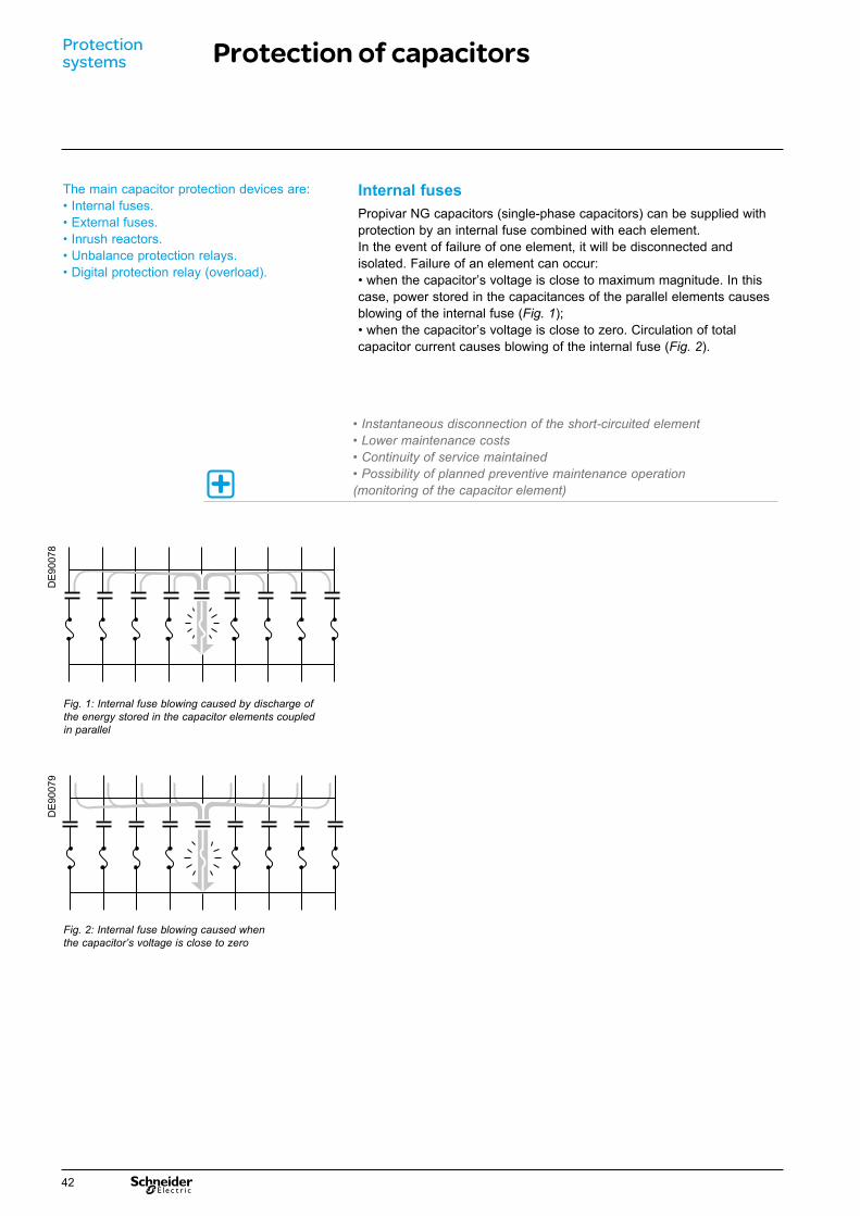
Fig. 1: Internal fuse blowing caused by discharge of the energy stored in the capacitor elements coupled in parallel
Internal fuses Propivar NG capacitors (single-phase capacitors) can be supplied with protection by an internal fuse combined with each element.In the event of failure of one element, it will be disconnected and isolated. Failure of an element can occur:• when the capacitor’s voltage is close to maximum magnitude. In this case, power stored in the capacitances of the parallel elements causes blowing of the internal fuse (Fig. 1);• when the capacitor’s voltage is close to zero. Circulation of total capacitor current causes blowing of the internal fuse (Fig. 2).
• Instantaneous disconnection of the short-circuited element• Lower maintenance costs• Continuity of service maintained• Possibility of planned preventive maintenance operation (monitoring of the capacitor element)
Fig. 2: Internal fuse blowing caused when the capacitor’s voltage is close to zero
DE
9007
8D
E90
079
42

Inrush reactors Inrush reactors are connected in series to each step and serves to limit the current peak which occurs during switch-on operations. The inductance value is chosen to ensure that the peak current occurring during operations always remain less than 100 times the current rating of the bank.Main characteristics:• Air-core reactors, dry type.• Single-phase configuration.• Indoor or outdoor installation.• In compliance with IEC or equivalent standards.
Unbalance protectionThis protection generally applies to banks of:• medium or high power ( > 1200 kvar);• provided with single-phase capacitors;• double star connection compulsory.Unbalance or differential protection is a protection system capable of detecting and responding to a partial capacitor fault.It consists of a current transformer connected between two electrically balanced points combined with a current relay. In the event of a fault in a capacitor, the result is an unbalance, hence a circulating current in the current transformer which will cause, via the relay, opening of the bank’s switchgear (circuit breaker, switch, contactor, etc.). Note: there is no unbalance protection with three-phase capacitors.
External fuses The external fuses for capacitors are designed to eliminate capacitors at fault, so as to allow the other steps of the bank to which the unit is connected to continue to operate. They also eliminate external sparkover on capacitor bushings. The operation of an external fuse is generally determined by the fault current supplied by the network and by the discharge energy coming from the capacitors connected in parallel with the capacitor at fault.The initial failure is usually an individual element (wafer) of the capacitor. This failure results in a short circuit which applies to all the elements in parallel and thus eliminates a series set of elements. If the cause of the initial failure remains, failure of the successive series sets (which sustain a voltage increase with each elimination of a series set) will occur. This causes a current increase in the capacitor until the external fuse operates, eliminating the failed capacitor from the circuit.
Protection by external HRC (High Rupturing Capacity) fuses incorporated in the bank is very suitable (technically and economically) for capacitor banks of:• low power (< 1 200 kvar);• provided with three-phase capacitors;• mains voltage < 12 kV.The fuse rating will be chosen with a value ranging between 1.7 and 2.2 times the current rating of the bank (1.5 to 2.2 with detuning reactors).Blowing of HRC fuses is generally caused by a non-resistive short circuit. The blown fuse indication is a visual means of checking the state of the fuse.
Current transformer for unbalance protection
PE
9010
4
Inrush reactors
PE
9010
3
HRC fuses
PE
9009
2
43

Protections Arc fault detectorVamp 120
PE
9050
1
Functions Vamp arc flash protection maximizes the personnel safety and minimizes the material damage of the installation in the most hazardous power system fault situations. The arc protection unit detects an arc flash in an installation and trips the feeding breakers.On detection of a fault the arc flash protection unit immediately trips the concerned circuit breaker(s) to isolate the fault.An arc flash protection system operates much faster than conventional protection relays and thus damage caused by an arc short circuit can be kept to a minimum level.
System features • Integrated 19 - 256 V AC/DC aux. supply.• Up to 4 arc sensors.• Selective trip for 2 zones and possibility for generator set emergency trip (separate contact).• Operation time 7 ms (including the output relay).• Non-volatile trip status.• NO and NC trip outputs:- self-supervision,- straight-forward installation,- cost efficient solution.
Sensors • Point sensor:- arc detection,- self-monitored,- cable length adjustable from 6 m to 20 m.
Standards
Benefits• Personnel safety• Reduces production losses• Extended switchgear life cycle• Reduced insurance costs• Low investment costs and fast installation• Reliable operation
Disturbance standards Electromagnetic compatibility Emission EN 61000-6-4Immunity EN 61000-6-2
Test voltage standards Electrical security tests Insulation test voltage IEC 60255-5Impulse test IEC 60255-5
Mechanical standards Shock response IEC 60255-21-2, class IShock withstand IEC 60255-21-2, class IBump test IEC 60255-21-2, class IVibration Sinusoidal response IEC 60255-21-1, class I
Sinusoidal endurance IEC 60255-21-1, class IEnvironmental conditions Operating temperature -10 to +55°C
Transport and storage temperature - 40 to +70°CRelative humidity < 75% (1 year, average value)
< 90% (30 days per year, no condensation permitted)
Degree of protection (IEC 60529) IP20
• Schneider Electric VAMP’s arc flash fault protection functionality enhances the safety of both people and property and has made Schneider Electric VAMP a pioneer in the field of arc flash protection with more than 10.000 VAMP arc flash systems and units with over 150.000 arc detecting sensors in service worldwide.
44

45

ComponentsContents
Power Factor Correction and harmonic filtering
MV Propivar NG capacitor 48Varlogic power factor controller 50Current Transformer 51Potential Transformer 51Detuning or filtering reactor 52Rollarc contactor SF1& SF2 circuit breakers 53Vacuum contactor CBX3-C 54SF1& SF2 circuit breakers 56Control and monitoring unit 57Digital protection relay: Sepam 58
47

Components Propivar NG capacitor unit
Propivar NG capacitors are used to build capacitor banks for reactive energy compensation on medium- and high-voltage networks. Through various assemblies, they can cover various reactive power ratings according to the mains voltage, frequency and level of harmonic distortion of the network.
Single phase capacitor Three phase and double capacitor
Description A high-voltage Propivar NG capacitor takes the form of a metal enclosure with terminals on top.This enclosure contains a set of capacitor elements. Wired in series-parallel groups, they can form unit elements of high power for high network voltages. Two types are proposed:• with internal fuses (Single Phase Capacitor, Double Capacitor), available with Q > 100 kvar, some possible limitations according to voltage level;• without internal fuse (Three Phase or Single Phase Capacitor, Double Capacitor). These capacitors are provided with discharge resistors to reduce the residual voltage to 75 V, 10 minutes after their switching off.On request, the capacitors can be supplied with resistors to reduce the residual voltage to 50 V in 5 minutes.
Composition The capacitor elements forming the Propivar NG capacitor are made of:• folded aluminium electrodes;• polypropylene films;• non PCB (chlorine free) dielectric fluid (Jarylec C101).
Main characteristics Propivar NG capacitors have an exceptional long service life increased by their low losses, their chemical and heat stability and their resistance to overvoltages and overcurrents, as well as their withstand to environment (salt mist, sulphurous atmosphere, vibrations).
Heat stabilityAt low temperature, these capacitors are able to withstand switching transient. At higher ambient temperatures, they provide very limited heating, so that there is no risk of modification of the dielectric insulation properties.
Chemical stabilityTransient surges in networks and partial discharge levels cause accelerated ageing of capacitor elements. The exceptionally long service life of Propivar NG capacitors is due to the intrinsic properties of the dielectric fluid, namely:• very high chemical stability;• high power of absorption of gases generated during partial discharges;• very high dielectric strength.
Overvoltage and overcurrent resistanceCapacitors can accept:• an overvoltage of 1.10 UN, 12 h per day;• an overvoltage at power frequency of 1.15 UN, 30 minutes per day;• a permanent overcurrent of 1.3 IN.Their resistance is tested according to IEC 60871-2:• 850 cycles at an overvoltage level of 2.25 UN (cycle duration 15 periods);• ageing tests at 1.4 UN (1000 hours).
Salt mistThe capacitors have been tested to salt mist according to IEC 60068-2-11 (672 hours) with temperature criteria from NPX 41-002.
Sulphurous atmosphereThe capacitors have been tested to sulphurous atmosphere according to NFT 30-055 (30 days).
VibrationsThe withstand of the capacitors have been tested according to IEC 60068-2-6 up to 3M4 level.
Propivar NG capacitor with internal fuse, built with 4 series group of 12, parallel elements complete with discharge resistors
PB
1081
51
PB
1081
53
DB
1088
07
48
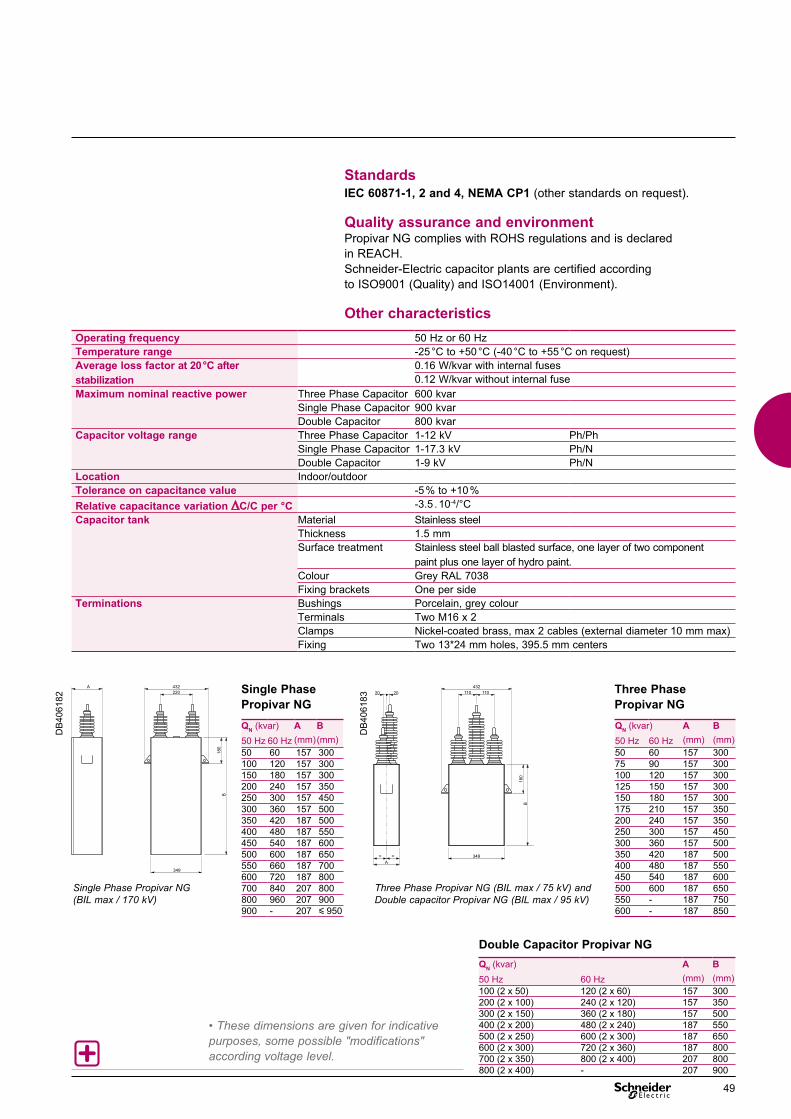
Standards IEC 60871-1, 2 and 4, NEMA CP1 (other standards on request).
Quality assurance and environment Propivar NG complies with ROHS regulations and is declared in REACH.Schneider-Electric capacitor plants are certified according to ISO9001 (Quality) and ISO14001 (Environment).
Other characteristics
Single Phase Propivar NG (BIL max / 170 kV)
Three Phase Propivar NG (BIL max / 75 kV) and Double capacitor Propivar NG (BIL max / 95 kV)
Operating frequency 50 Hz or 60 HzTemperature range -25 °C to +50 °C (-40 °C to +55 °C on request) Average loss factor at 20 °C after stabilization
0.16 W/kvar with internal fuses0.12 W/kvar without internal fuse
Maximum nominal reactive power Three Phase Capacitor 600 kvarSingle Phase Capacitor 900 kvarDouble Capacitor 800 kvar
Capacitor voltage range Three Phase Capacitor 1-12 kV Ph/PhSingle Phase Capacitor 1-17.3 kV Ph/NDouble Capacitor 1-9 kV Ph/N
Location Indoor/outdoorTolerance on capacitance value -5 % to +10 %Relative capacitance variation ∆C/C per °C -3.5 . 10-4/°CCapacitor tank Material Stainless steel
Thickness 1.5 mmSurface treatment Stainless steel ball blasted surface, one layer of two component
paint plus one layer of hydro paint.Colour Grey RAL 7038Fixing brackets One per side
Terminations Bushings Porcelain, grey colourTerminals Two M16 x 2Clamps Nickel-coated brass, max 2 cables (external diameter 10 mm max)Fixing Two 13*24 mm holes, 395.5 mm centers
QN (kvar) A B50 Hz 60 Hz (mm)(mm)50 60 157 300100 120 157 300150 180 157 300200 240 157 350250 300 157 450300 360 157 500350 420 187 500400 480 187 550450 540 187 600500 600 187 650550 660 187 700600 720 187 800700 840 207 800800 960 207 900900 - 207 y 950
QN (kvar) A B50 Hz 60 Hz (mm) (mm)100 (2 x 50) 120 (2 x 60) 157 300200 (2 x 100) 240 (2 x 120) 157 350300 (2 x 150) 360 (2 x 180) 157 500400 (2 x 200) 480 (2 x 240) 187 550500 (2 x 250) 600 (2 x 300) 187 650600 (2 x 300) 720 (2 x 360) 187 800700 (2 x 350) 800 (2 x 400) 207 800800 (2 x 400) - 207 900
QN (kvar) A B50 Hz 60 Hz (mm) (mm)50 60 157 30075 90 157 300100 120 157 300125 150 157 300150 180 157 300175 210 157 350200 240 157 350250 300 157 450300 360 157 500350 420 187 500400 480 187 550450 540 187 600500 600 187 650550 - 187 750600 - 187 850
Single Phase Propivar NG
Three Phase Propivar NG
Double Capacitor Propivar NG
A 432220
180
B
349
DB
4061
82
20 20
A= = 349
432110 110
B180
DB
4061
83
• These dimensions are given for indicative purposes, some possible "modifications" according voltage level.
49

Components Varlogic power factor controller
Varlogic controllers constantly measure the installation’s reactive power and manage connection and disconnection of capacitor steps to obtain the desired power factor.The NRC12 can manage up to 12 capacitor steps and has extensive functionalities including Modbus communication (optional). It simplifies the commissioning, monitoring and maintenance of power factor correction equipment.
NRC12 technical specifications Number of steps 12Dimensions 155 x 158 x 80 mmFrequency 50 Hz nominal (range 48...52 Hz) 60 Hz nominal (range 58...62 Hz)Monitoring current 0…1 A or 0...5 AMonitoring voltage* 80…690 V (nominal, max. 115%)Measured power display 100 000 kVANominal consumption 13 VATensions d’alimentation 110 V nominal, (range 88...130 V) 230 V nominal, (range 185...265 V) 400 V nominal, (range 320...460 V)Output relay 250 V, 2 AScreen Graphic display, resolution 64x128 pixels, backlitDegree of protection IP41 front panel, IP20 rear panelTarget pf (cos ϕ) range 0.85 ind …1.00 … 0.90 capResponse current C/K 0.01 ... 1.99, symmetric or asymmetricReconnection time 10…900 sResponse time 20 % reconnexion time, min. 10 sValues displayed cos ϕ, Iact, Ireact, Iapp, IRMS/I1, P, Q, S, THD (U) and harmonic voltages, THD(I) and harmonic current, internal and external temperatureType of installation Flush mounting or on DIN railEnclosure Impact-resistant PC/ABS, UL94V-0Operating temperature 0…60°C Alarm history List of the last 5 alarmsStepped meter YesFan control by dedicated relay Yes. 250 Vac, 8AAlarm contact Yes. 250 Vac, 8ATC range 25/1 … 6000/1 or 25/5 … 6000/5Detection Response time > 15 msof voltage dips Communication Modbus protocol with CCA-01 (option)
Varlogic NRC12
* Voltage transformer ratio input allows display/monitoring of primary voltage in MV installation
PB
1000
33_S
E
PB
1000
32_S
E
50

Components Current TransformerPotential Transformer
Current Transformer Composition and typesCurrent Transformers are designed to perform protection and monitoring functions.• Detection of overcurrents in capacitor banks and supply of a signal to the protection relay.• Supply of a signal to the power factor controller.
They are of the following types:• wound (most common type): when the primary and secondary include a coil wound on the magnetic circuit;• bushing type: primary formed by a conductor not isolated from the installation;• toroidal: primary formed by an isolated cable.
The double star arrangement and unbalance protection require the use of special current transformers (class X).
Current Transformers (CT) meet standard IEC 60044-1.Their function is to supply the secondary circuit with a current that is proportional to that of the MV circuit on which they are installed.The primary is series-mounted on the MV network and subject to the same over-currents as the latter and withstands the MV voltage.
Magnetic core Magnetic core
DE
5234
4
DE
5235
9
Wound type primary current transformer
Closed core type current transformer
PE
5603
0
Current Transformer
Potential Transformer Composition and typesPotential Transformers are designed to perform protection and monitoring functions.• Detection of over-/under-voltages in capacitor banks and supply of a signal to the protection relay.• Supply of a signal to the power factor controller.
Potential Transformers (PT) meet standard IEC 60044-2.They have two key functions:• adapting the value of MV voltage on the primary to the characteristics of metering protection devices by supplying a secondary voltage that is proportional and lower;• isolating power circuits from the metering and/or protection circuit.
PE
5670
0
Phase-earth Potential Transformer
51
Components Detuning or filtering reactor
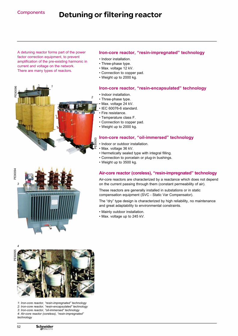
A detuning reactor forms part of the power factor correction equipment, to prevent amplification of the pre-existing harmonic in current and voltage on the network.There are many types of reactors.
Iron-core reactor, “resin-impregnated” technology • Indoor installation.• Three-phase type.• Max. voltage 12 kV.• Connection to copper pad.• Weight up to 2000 kg.
Iron-core reactor, “resin-encapsulated” technology • Indoor installation.• Three-phase type.• Max. voltage 24 kV.• IEC 60076-6 standard.• Fire resistance.• Temperature class F.• Connection to copper pad.• Weight up to 2000 kg.
Iron-core reactor, “oil-immersed” technology • Indoor or outdoor installation.• Max. voltage 36 kV.• Hermetically sealed type with integral filling.• Connection to porcelain or plug-in bushings.• Weight up to 3500 kg.
Air-core reactor (coreless), “resin-impregnated” technology Air-core reactors are characterized by a reactance which does not depend on the current passing through them (constant permeability of air).
These reactors are generally installed in substations or in static compensation equipment (SVC - Static Var Compensator).
The “dry” type design is characterized by high reliability, no maintenance and great adaptability to environmental constraints.
• Mainly outdoor installation.• Max. voltage up to 245 kV.
1: Iron-core reactor, “resin-impregnated” technology2: Iron-core reactor, “resin-encapsulated” technology3: Iron-core reactor, “oil-immersed” technology4: Air-core reactor (coreless), “resin-impregnated” technology
3
PE
9009
4
4
PE
9009
5
1
2 PE
9009
6
PE
9009
3
52

Components Rollarc contactor
The Rollarc three-pole type contactor, for indoor use, employs SF6 for insulation switching.The breaking principle is that of the rotating arc. The basic device consists of three pole units mounted in a single insulating enclosure. The insulating enclosure containing the live parts of these poles is filled with SF6 at a relative pressure of 2.5 bar.The Rollarc contactor is available in two types:• R400 contactor, with magnetic holding.• R400D contactor, with mechanical latching.
Applications Control and protection of• MV motors.• Capacitor banks and power transformers.
Reference standards • IEC 60470 standard: High-Voltage Alternating Current Contactors and Contactor-Based Motor-Starters.• IEC 62271-105 standard: High-voltage switchgear and controlgear, Alternating current switch-fuse combinations.
• Equipment requiring no maintenance on live parts.• High mechanical and electrical endurance.• Insensitivity to the environment.• Gas pressure can be monitored constantly.
1: MV connections 2: LV connections3: Auxiliary contacts4: Pressure switch5: Electromagnetic control mechanism 6: Mechanical latching device (R400D)7: Opening release 8: Mounting points9: Insulating enclosure 10: Rating plate
Rollarc contactor (cutaway)
PE
5676
1
Rollarc contactor (connections)
PE
9010
5
Electrical characteristicsRated Insulation level Breaking capacity Rated Making capacity Short-time Mechanicalvoltage current thermal enduranceUR (kV) Inpulse 1 mn with IR with current50/60Hz 1,2/50μs 50/60Hz fuses fuses 3skV kV peak kV rms kA kA A kA peak kA kA rms7,2 60 20 10 50 400 25 125 10 100 000 operations12 60 28 8 40 400 20 100 8
Maximum operable powerVoltage (kV) Without fuse With integrated fuse Power (kvar) Power (kvar) 3,3 1255 790 4,16 1585 8006,6 2510 127010 3810 960 12 4570 1155
53

Composants Vacuum contactor CBX3-C
The three-phase CBX3-C contactor, designed for indoor applications, uses vacuum technology for insulation and arc-breaking.It is specifically designed for breaking capacitive loads.
Applications The design and contact materials fulfil the general requirements for contactor applications of capacitor bank feeders in various industrial sectors, such as:• metallurgy,• mining,• oil and gas,• electrical distribution.
CBX comes with an electronic auxiliary supply (EAS) as standard equipment for easy configuration and low consumption.
Standards Schneider Electric vacuum contactors have been designed to meet or exceed the requirements of international standards:• CEI 60470,• ANSI C37,• BS EN 60470,• NEMA ICS,• GB (Chinese).
Electrical characteristics
PE
9024
3
CBX3-C
Rated Voltage (kV) 7.2 / 12Power frequency withstand voltage (kV)
20 / 28
Impulse withstand voltage (BIL) (kV) 60 / 75Capacitive load Rated operating current (A) 400
Maximum capacitor bank rating (kvar)
3360 / 5600
Inrush current (kAp) 20Short time withstand current 1 s (kA) 4
Peak on ½ cycle (kAp) 25Mechanical endurance (N°) 3 millionsElectrical endurance at rated current (N°)
500 000
Temperature range (°C) -5 to +40Number of poles 1P - 3P
54

Electronic Auxiliary Supply (EAS) A selection of only two standard electronic circuits are required to manage all usual auxiliary voltages:• 24 to 60 V DC,• 110 to 250 V AC/V DC.
Benefits• Low power consumption.• Improved reliability.• Operation counter (optional).• Optional 100 ms delay to open.• Reduced thermal dissipation.• Standardized schematics.
ControlClosing coil supply voltage (V) DC: 24, 48, 60, 110, 125, 220, 250
AC: 110, 120, 220, 240Latch supply voltage (V) DC: 24, 48, 110, 240
AC: 110, 240CBX
Power consumption (W) Closing 500Magnetic holding 150Magnetic holding with EAS 80
Latch voltage supply Power consumption (W) 240Endurance (N°) 200000
OptionsCBX
Auxiliary contacts 5 NO + 5 NCElectronic supply (EAS) YesOpening delay 100 ms OptionOperation counter OptionInsulation level at 42 kV OptionMechanical latch Option
DimensionsWidth (mm) 343Length (mm) 333Height (mm) 258Weight (kg) 28
• Fast switching rate.• Long mechanical life.• Low power losses thanks to electronic auxiliary supply.
55

Components SF1 & SF2 circuit breakers
Description The SF circuit breaker, in its basic fixed version, consists of:• 3 main poles, linked mechanically and each comprising an insulating enclosure of the “sealed pressure system” type. The sealed enclosure is filled with SF6 at low pressure.• A spring type energy storage manual control (electrical on option). This means the device’s making speed and breaking speed are independent of the operator. When it is provided with electric control, the circuit breaker can be remotely controlled and resetting cycles can be performed.• Front panel with the manual control and status indicators.• Downstream and upstream terminals for power circuit connection.• A terminal block for connection of external auxiliary circuits. Depending on these characteristics, the SF circuit breaker is available with a front or side control mechanism.
Options • Electric control• Supporting frame fitted with rollers and floor mounting brackets for a fixed installation.• Circuit breaker locking in open position by lock installed on the control front plate.• SF6 pressure switch for highest performance.
Applications The SF devices are three-pole MV circuit breakers for indoor use. They are chiefly used for switching and protection of networks from 12 to 36 kV in the distribution of primary and secondary power.
With self-compression of the SF6 gas, which is the switch-off technique used in these circuit breakers, the establishment or interruption of any type of capacitive or inductive current is performed without any dangerous overvoltage for the equipment connected to the network. The SF circuit breaker is therefore highly appropriate for the switching of capacitor banks.
The SF circuit breaker of the Schneider Electric equipment range is used for switching on capacitor banks or steps.This circuit breaker uses SF6 as dielectric.It has been especially tested for the specific operation of capacitor banks.
SF1 circuit-breaker
PE
5650
1
SF2 circuit-breaker
PE
5650
3
SF1 fixed SF2 fixedSide or front operating mechanism Front operating mechanism Rated voltage Ur (kV, 50/60 Hz)
Rated short-circuit breaking current (Isc )25 kA from 12.5 to 25 kA from 12.5 from 25 31.5 kA to 40 kA to 40 kA
Rated current (Ir )630 A from 400 to 1 250 A from 630 to 3 150 A 2 500 A
Rated switching capacitive current (Ic )440 A from 280 to 875 A from 440 to 2 200 A 1 750 A
12 kV
17.5 kV
40.5 kV
24 kV 24 kV
36 kV 36 kV
56

Description These enclosures are designed for indoor installation.They comprise the following elements:• A Varlogic power factor controller;• A Sepam digital protection relay:• Unbalance protection relays;• Indicator lamps- “ON”- for each step, “Step ON”, “Step OFF”, “Unbalance alarm”, “Unbalance trip”.
Option A three-position selector switch:• “Auto”: The steps are controlled automatically by the power factor controller;• “Manual”: The steps are controlled manually by means of a 2-position selector switch located on the enclosure (1 selector switch per step);• “0”: The steps are disconnected (no control, automatic or manual, is possible).
Components Control and monitoring unit
The function of these units is to control and protect capacitor banks.
Monitoring and control unit1. Varlogic power factor controller 2. Sepam digital protection relay
PE
9010
6
1 21 2
57
Components Sepam protection relay
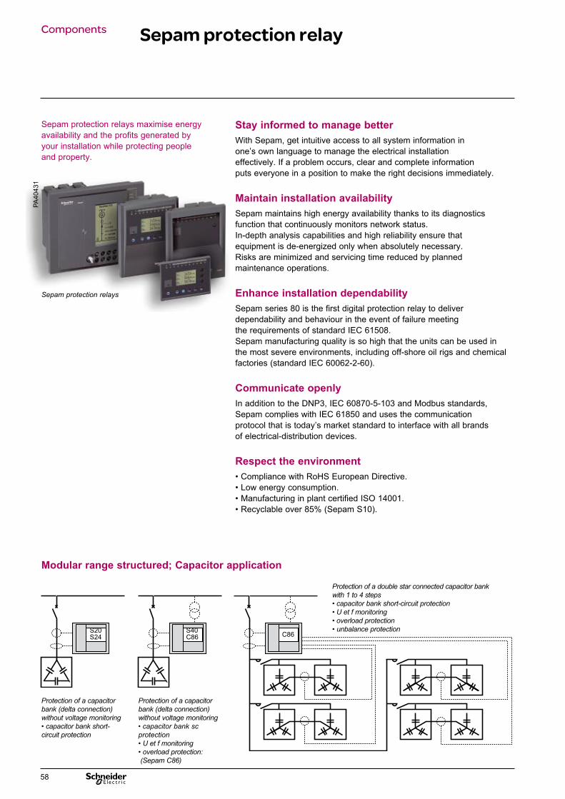
Sepam protection relays maximise energy availability and the profits generated by your installation while protecting people and property.
Stay informed to manage betterWith Sepam, get intuitive access to all system information inone’s own language to manage the electrical installationeffectively. If a problem occurs, clear and complete informationputs everyone in a position to make the right decisions immediately.
Maintain installation availabilitySepam maintains high energy availability thanks to its diagnosticsfunction that continuously monitors network status.In-depth analysis capabilities and high reliability ensure thatequipment is de-energized only when absolutely necessary.Risks are minimized and servicing time reduced by plannedmaintenance operations.
Enhance installation dependability Sepam series 80 is the first digital protection relay to deliverdependability and behaviour in the event of failure meeting the requirements of standard IEC 61508. Sepam manufacturing quality is so high that the units can be used in the most severe environments, including off-shore oil rigs and chemical factories (standard IEC 60062-2-60).
Communicate openlyIn addition to the DNP3, IEC 60870-5-103 and Modbus standards,Sepam complies with IEC 61850 and uses the communicationprotocol that is today’s market standard to interface with all brandsof electrical-distribution devices.
Respect the environment • Compliance with RoHS European Directive. • Low energy consumption.• Manufacturing in plant certified ISO 14001. • Recyclable over 85% (Sepam S10).
S20S24
S40C86 C86
Protection of a capacitor bank (delta connection) without voltage monitoring • capacitor bank short-circuit protection
Protection of a capacitor bank (delta connection) without voltage monitoring • capacitor bank sc protection• U et f monitoring• overload protection: (Sepam C86)
Protection of a double star connected capacitor bank with 1 to 4 steps • capacitor bank short-circuit protection• U et f monitoring• overload protection• unbalance protection
Modular range structured; Capacitor application
Sepam protection relays
PA40
431
58
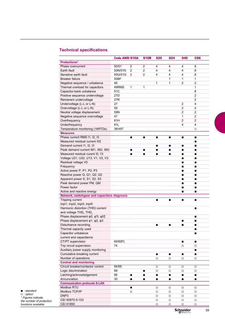
Technical specifications
Code ANSI S10A S10B S20 S24 S40 C86Protections*Phase overcurrent 50/51 2 2 4 4 4 8 Earth fault 50N/51N 2 2 4 4 4 8 Sensitive earth fault 50G/51G 2 2 4 4 4 8Breaker failure 50BF 1 1 1 Negative sequence / unbalance 46 1 1 2 2 Thermal overload for capacitors 49RMS 1 1 1Capacitor-bank unbalance 51C 8Positive sequence undervoltage 27D 2Remanent undervoltage 27R 2Undervoltage (L-L or L-N) 27 2 4 Overvoltage (L-L or L-N) 59 2 4Neutral voltage displacement 59N 2 2Negative sequence overvoltage 47 1 2Overfrequency 81H 2 2Underfrequency 81L 4 4Temperature monitoring (16RTDs) 38/49T vMeasuresPhase current RMS I1, I2, I3 ◼ ◼ ◼ ◼ ◼ ◼ Measured residual current I0Σ ◼Demand current I1, I2, I3 ◼ ◼ ◼ ◼Peak demand current IM1, IM2, IM3 ◼ ◼ ◼ ◼ ◼ ◼Measured residual curent I0, I’0 ◼ ◼ ◼ ◼ ◼ ◼ Voltage U21, U32, U13, V1, V2, V3 ◼ ◼Residual voltage V0 ◼ ◼Fréquency ◼ ◼Active power P, P1, P2, P3 ◼ ◼Reactive power Q, Q1, Q2, Q3 ◼ ◼Apparent power S, S1, S2, S3 ◼ ◼Peak demand power PM, QM ◼ ◼Power factor ◼ ◼Active and reactive energy ◼ ◼ Network, switchgear and capacitors diagnosisTripping current ◼ ◼ ◼ ◼tripI1, tripI2, tripI3, tripI0 Harmonic distortion (THD) current ◼and voltage THDi, THDu
Phase displacement φ0, φ'0, φ0Σ ◼Phase displacement φ1, φ2, φ3 ◼ ◼Disturbance recording ◼ ◼ ◼ ◼Thermal capacity used ◼Capacitor unbalance ◼current and capacitanceCT/PT supervision 60/60FL ◼ ◼Trip circuit supervision 74 v vAuxiliary power supply monitoring ◼Cumulative breaking current ◼ ◼ ◼ ◼Number of operations v v v vControl and monitoringCircuit breaker/contactor control 94/69 v v v vLogic discrimination 68 ◼ v v v vLatching/acknowledgement 86 ◼ ◼ ◼ ◼ ◼ ◼Annunciation 30 ◼ ◼ ◼ ◼ ◼ ◼Communication protocols S-LANModbus RTU ◼ v v v vModbus TCP/IP v v v v vDNP3 v v v vCEI 60870-5-103 v v v vCEI 61850 v v v v
◼ : standard v : option* Figures indicate the number of protection functions available
59


Specific equipments Contents
Power Factor Correction and harmonic filtering
Hybrid Var Compensator (HVC) 62Passive harmonic filters 64Blocking circuits 65
61

Specific equipments Hybride Var Compensator (HVC)
Hybrid Var Compensator (HVC)Description The equipment comprises a fixed MV bank of shunt capacitors with detuning reactor, and an AccuSine electronic device combined with an LV/MV step-up transformer.
HVC (Hybrid Var Compensator) equipment is designed to perform economical reactive energy compensation in real time.Its use can:• improve the quality of public and industrial networks by reducing or eliminating voltage fluctuations, power fluctuations, etc.;• increase the capacity of existing networks by compensating losses due to reactive energy;• allow optimum coupling of renewable energies (wind-power, solar power) to the network through an appropriate response to normative constraints
25 / 4.16 kV 25 / 4.16 kV
2000 A 2000 A
CT (3) 1000/5 CT (3) 1000/5
1200A
4.16kV 4.16kV
CT (3) 1000:5
4.16 / 0.48 kV
2000A
6 x 250kvarAccusine
1225 kvarMV bank
with detuning reactors
Example of implementation
PE
9008
2
PE
9004
6
DE
9008
3
62

Operation The fixed capacitor bank constantly injects a capacitive reactive current into the network. The electronic device injects a reactive, capacitive or inductive current, continually and in less than one period (20 ms - 50 Hz), to compensate the major rapid fluctuations in reactive power consumption due to the load.
Characteristics • Injection of reactive energy in “leading” or “lagging” mode.• Response time less than one cycle.• Power factor adjustable up to unity.• Reactive energy compensation without transient.• Continuous compensation.• Separate monitoring of each phase for unbalanced loads.
Applications • Energy- Connection of wind-power or solar farms.• Industry- Arc furnaces: voltage regulation and flicker attenuation.- Welding machines: voltage regulation and flicker attenuation.- Crushers: flicker attenuation.- Pumping stations: starting assistance for high-powered MV motors.- Cold/hot rolling mills: attenuation of harmonics and improvement of the power factor of rapidly fluctuating loads.
AccuSine range
PE
9007
4D
E90
084
fixed kvarloadAccuSineresult kvar
63

Schneider Electric can propose numerous passive harmonic filtering solutions in medium and high voltage, for 50 or 60 Hz networks.These solutions are custom designed on a case by case basis. A preliminary site audit and a precise definition of needs (objectives to be achieved, etc.) are essential to guarantee the performance of this type of solution.
Passive harmonic filters Technical characteristics • Rated frequency: 50 Hz or 60 Hz.• Insulation: 72.5 kV (for other values, please consult us).• Maximum reactive power: 35 Mvar (for other values, please consult us).• Reactors: single-phase, dry, air-core; they are most commonly used for passive filters.• Other components, such as resistors, can also be used in the design of passive filters.• Tuning frequencies: chosen according to the harmonics to be filtered and the performance to be achieved (a preliminary site audit is crucial to make the right choices).
Passive harmonic filters Specific equipments
PE
9009
7
Passive harmonic filter
64

Specific equipments Blocking circuits
In its range of solutions, Schneider Electric has low-frequency passive blocking circuits which can prevent disturbance by musical-frequency remote control signals emitted by the power distributor, especially in the context of installation of an autonomous production unit.
These blocking circuits are often used in installations provided with cogeneration plants.
To meet the conditions required by the power distributor, the blocking circuit is defined on a case by case basis according to the characteristics of:• the HV power supply line of the source substation;• the HV/MV transformer of the source substation;• the remote control order injection device;• the load of the MV feeders;• the generating sets.
Principle The blocking circuit is implemented by placing in parallel an reactor and a capacitor element whose values have been calculated to allow blocking of a chosen frequency (175 Hz or 188 Hz in France, for example).
Technical characteristics(passive blocking circuit for 15 and 20 kV networks ) Tuning frequency 175 or 188 Hz (other frequencies on request)Insulation level Up to 24 kVAvailable ratings 200, 300 ou 400 A per phaseCharacteristics of components of 175 Hz blocking circuitsSingle-phase capacitors 207μF / 2100V, without internal fusesSingle-phase reactors 4mH, without magnetic coreCharacteristics of components of 188 Hz blocking circuitsSingle-phase capacitors 179μF / 2100V, without internal fusesSingle-phase reactors 4mH, without magnetic coreMaximum ambient temperature 45 °CAltitude < 1000 mMounting Juxtaposed (capacitors upright, alongside the reactor) or on top of one another (capacitors installed in a rack, under the reactor)IP 00 on unpainted aluminium substrate
Juxtaposed mounting
Reactor
300900900
1640
400
Superimposed mounting
Reactor
Path AL6060
Capacitor
11004ǿ1320 20
Insulator 24kV
In-line arrangement Delta arrangement
6600 min6600 min.
44001200
1100 11001000
Phase 1
Phase 1
Phase 2
Phase 2
Phase 3 Phase 3
12001100 1100 1100
1200
1200
1155
600
1150
4150
min
.
2400
1100 1100
Blocking circuit
DE
9005
4
DE
9005
4
DE
9005
5
DE
9005
5
PE
9008
3
65


Installation (drawings, dimensions)Contents
Power Factor Correction and harmonic filtering
CP 214, CP 214 SAH, CP 227, CP 254 68CP 229, CP 230, CP 253, CP 253 SAH 69
67

Installation( drawings, dimensions)
CP 214, CP 214 SAH, CP 227, CP 254
CP 214
Dimensions and weight• H: 1700 mm, L : 900 mm, D: 1200 mm.• Approximate weight: 425 to 560 kg.
Drawing
CP 214 SAHDimensions and weight• H : 1900 mm, L : 2000 mm, D : 1100 mm.• Approximate weight: 600 to 1000 kg.
Drawing
L D
H
80
L D
H
80
DE
9006
2
CP 254Dimensions and weight• Insulation up to 24 kVH : 2000 mm, L : 2600 mm, D : 1400 mm.• 36 kV insulationH : 2100 mm, L : 3000 mm, D : 2100 mm.• Approximate weight: 450 to 1550 kg.
Drawing
L D
H
80
DE
9007
6
CP 227Dimensions and weight• Isolement 24 kVH : 2000 mm, L : 1400 mm, D : 1400 mm.• 36 kV insulationH : 2000 mm, L : 3000 mm, D : 2100 mm.• Approximate weight: 450 to 1550 kg.
Drawing
L D
H
80
DE
9006
4M
T201
35
68

L D
H
80
CP 253
Number of steps 1 H : 2 000, L : 1 500, D : 1 6002 H : 2 000, L : 2 600, D : 1 6003 H : 2 000, L : 3 700, D : 1 6004 H : 2 000, L : 4 800, D : 1 6005 H : 2 000, L : 5 900, D : 1 600
Dimensions
L D
H
80
Number of steps 1 H : 2 000, L : 1 500, D : 2 4002 H : 2 000, L : 2 600, D : 2 4003 H : 2 000, L : 3 700, D : 2 4004 H : 2 000, L : 4 800, D : 2 4005 H : 2 000, L : 5 900, D : 2 400
DimensionsCP 253 SAH
CP 229 CP 230
CP 229, CP 230, CP 253, CP 253 SAHD
E90
065 DE
9007
7
DE
9007
4D
E90
075
Drawing
Drawing
69


Services Contents
Power Factor Correction and harmonic filtering
Schneider Electric expertise 72Maintenance & end of life 73
71

Services Schneider Electric expertise
For more than 50 years, Schneider Electric has designed and manufactured power factor correction and harmonic filtering equipment.From the beginning, it was clear that on-site measurements were often decisive. That is why Schneider Electric set up a team of specialists to perform measurements, site audits, simulations and expert appraisals.Each category of service is organized on various levels. The level depends on the equipment used (power factor meter, harmonic recorder, network analyser, etc.) and the qualifications of the personnel involved.The “services” offering includes:• On-site measurements.• Installation, supervision and commissioning.• Repairs.• Simulations and studies.• Hire of measuring instruments (network analysers, etc.).• Training sessions.
Schneider Electric’s services Listen, Understand, Act,is the virtuous circle guaranteeing you the energy efficiency you need.• ListenThis means collecting information, about symptoms and other difficulties concerning the operation of the installation. It requires -> Audit -> specific measurements -> recording of the characteristic parameters of the network’s key points.• UnderstandOnce this information has been collected, the diagnosis must be drawn up, and the corrective actions must be identified and determined.• ActThis the decisive phase… removal of network disturbances, correction of the power factor, installation of standby or battery back-up networks… and it is also the heart of our expertise.
In all cases, the ideal solution is to correct, but also and above all to monitor the effectiveness of the installed solutions over a period of time; an installation is alive, and like any living thing its characteristics change over time.
In many countries, the local service team of Schneider Electric has the competencies and equipment needed to perform measurements, diagnoses, repairs, etc. as required.
The Schneider Electric specialists can be called on to provide support or their expertise for specific or extremely critical cases.
Training sessions can be organized to train or update the knowledge of your installation or maintenance teams.
Our specialists can also be called on to take part in conferences, seminars, presentations, etc. concerning power factor correction, harmonic filtering, quality of power, etc.
Installation diagnosis• Evaluation of the state of the capacitor banks.• Measurement of operating temperatures.• Recording of voltages, currents, active and reactive power levels.• Recording of harmonic voltage and current spectrums.• Recording of transient voltage and current phenomena.
Solution definition• Proposal of capacitor replacement and substitution plans.• Management of the destruction process.• Power factor correction upgrade.• Reduction of networks harmonic distorsion.
PE
9010
0
72
Maintenance Routine checksCheck and, if necessary, clean the ventilation systems (frequency depends on local conditions).
Annual checks• Check connection clamping.• Check insulator cleanliness.• Check bank U, I, C and capacitance C values.• Measure ambient temperature for the capacitor bank.• Check operation of the safety features.
Faults and solutions• Failure of a three-phase capacitorThis is revealed by blowing of one or more HRC fuses. The faulty capacitor is identified by capacitance measurement (capacitance fluctuation greater than 10% = faulty).In this case, the capacitor and the three HRC fuses must be replaced immediately.• Failure of a single-phase capacitorThis is revealed by unbalance protection tripping. The faulty capacitor is identified by a capacitance measurement for each capacitor (capacitance fluctuation greater than 10% = faulty).In this case, the capacitor must be replaced immediately (bank rebalancing is sometimes necessary; please consult us).
NB: For internal fuses, we also recommend replacing capacitors having sustained a capacitance fluctuation of more than 5%.
Propivar NG capacitor end of lifeThe capacitors of our product range contain a non-PCB dielectric fluid. Its recovery at end of life must necessarily be performed by a central waste oils recycling facility according to local requirements.
If the capacitor is damaged with leaking fluid, it must be placed on a tray fluid retention and transport to the treatment center must be made by an approved carrier.
Operations of dismantling and recovery at end of life (to be done over a holding tank)• Drill tank capacitor and recover oil impregnant which must follow an incineration path with energy recover.• Cut the tank under the cover, and remove the inner part of the capacitor.• Drain the inner part and the tank.• The tank capacitor steel is recyclable.• Separate cover and bushings from inner part.• The inner part of the capacitor must follow a shearing path, incineration and recovery metals.• The entire cover and bushings must be crushed for recovery of metals (steel, copper and brass).
Maintenance & end of lifeP
E90
090
PE
9009
1
73


Selection guide Contents
Power Factor Correction and harmonic filtering
Installation conditions & General characteristics 76Frame/enclosure & Propivar NG capacitors 77Additional equipment 78
75

Design guide Installation conditions General characteristics
General characteristics Type of bank (STD, DR or filter) v STD v DR v FilterRated voltage (kV)Power (kvar) Rated frequency (Hz) v 50 v 60Insulation levelMax. voltage for the equipment kVPower-frequency test voltage (50Hz - 1 mn) kV rmsImpulse test voltage (1.2 / 50 µs) kV peakConnection v Double star v Delta v H single-phase v Single-phase v OtherShort-circuit current withstand capacity v Depending on site conditions v Other kA sec v 1 v 3Auxiliary voltages VDC v 24 v 48 v 60 v 110 v 125 v 220 VAC v 110 v 127 v 220-230
Site conditions
CountryAltitude v ≤ 1000 m v > 1000 mAtmosphere v Normal v Saline v SO2
v OtherPollution / Creepage v Low I (16 mm/kV)distance, insulators v Moderate II (20 mm/kV)and bushings v High III (25 mm/kV) v Very high IV (31 mm/kV)Short-circuit current power (kA) Temperature (°C) v > -25°C v ≤ 40 °C v 45 °C v 50 °C v 55 °C
This form specifies all the data to be provided to Schneider Electric from the “price quote” phase to the “order execution” phase.
Standards
IEC vOthers v
76

Frame/enclosurePropivar NG capacitors
Design guide
Propivar NG capacitors Type v Three-phase v Single-phaseDesign voltage (V)Rated frequency (Hz) v 50 v 60Specification of steps N° 1 2 3 4 5 6 kvar sequenceInsulation levelMax. voltage for the equipment kVPower-frequency test voltage (50Hz - 1 mn) kV rmsImpulse test voltage (1.2 / 50 µs) kV peakInternal fuses v Yes v NoTerminal creepage distance v Supplier standard v Other mm mm/kV v 16 v 20 v 25 v 31Internal discharge resistors V/min v 75/10 v 50/5Temperature Max. (°C) v ≤ 40 v 45 v 50 v 55 Min. (°C) v -25 v OtherGradient v Supplier standard v Other V/μm
Frame/enclosure
Type v Indoor v Outdoor Degree of protection v IP 00 v IP 23 v IP 54 v Other: Frame material v Steel v Galvanised steel v Aluminium v Stainless steelPanel material v Steel v Galvanised steel v Aluminium v Stainless steelFrame coating v Bare v PaintedPanel coating v Bare v PaintedDouble roof v Yes v NoColour v Supplier standard v Other RALDoor v Supplier standard v Other Lock (type) v Supplier standard v Other
77

Design guide Additional equipment
Detuning reactors vType v Resin-impregnated v Resin-encapsulated v Oil-immersed v Air core v 1-phase v 3-phaseInstallation v Indoor v Outdoor v In enclosure v Outside the enclosureHarmonic order
Measuring PT vRated voltage (V/V) (primary/secondary)Discharge function v Yes v NoQuantity v 2 v 3
Inrush reactors v
Quick discharge reactors v
Fuses v
System for protection against single-phase operation v
Protection CT vPower (VA)Precision class v 5P v 3PNumber of protected phases v 1 v 2 v 3
Switching device vType v Circuit breaker v ContactorBreaking technology v SF6 v Vacuum
Unbalance relays vRelays v Supplier standard v Other TypeThresholds v Trip v Alarm and tripMounting v Supplied separately v In bank v In enclosure or cabinet with the control and monitoring components
78

Additional equipmentDesign guide
Combined disconnector (line disconnector + ground switch) vEarthing switch connection v Line side v Load side
Earthing switch vType v 3-pole v 5-poleEarthing switch connection v Line side v Load sideQuantity v 1 per step v 1 per bank
Line disconnector v
Surge arresters (by default one per phase) v
Accessories vVentilation v Supplier standard v Other Type Lighting in bank v Yes v No
Interlocking system v v Supplier standard scheme v Other, to be defined
Monitoring/Control vNumber of steps to be controlledInstallation v Cabinet v Cubicle v In bankController v Yes v No Type v NR6/NR12 v NRC12 Sequence Modbus com. v Yes v No U (V) measurement I (A) measurement v 1 A secondary v 5 A secondaryProtection relay Functions v Unbalance v Over current v Over voltage v Other: Type Quantity v Per step v OverallAuto / 0 / Manual function v Yes v NoIndicator lamps By default v Aux. voltage presence v ON / step v OFF / step v Alarm-Unbalance-Blown fuse Other
79


Technical guideContents
Power Factor Correction and harmonic filtering
Reminders concerning reactive energy 82Reactive energyReactive energy compensationReactive energy and network componentsPower factors of typical equipment
Why compensate? 84Economic benefits Technical benefits Reduction in transmission losses according to the power factor improvementEconomic evaluation of compensation
Method for determining compensation 86Stage one: Calculation of reactive powerStage two: Choice of compensation modeStage three: Choice of compensation typeStage four: How to allow for harmonics
Control of capacitor banks 90General characteristics of switchgear and controlgearType of switchgear and controlgearSwitching ON capacitor banksSwitching ON capacitor banks, synthesisSwitching OFF capacitor banks Switchgear used for capacitor controlMedium voltage switchgear characteristics
Protection and circuit diagrams of capacitor banks 93CapacitorsDelta-connected bankBank connected in double star
Typical cases of compensation 94MV asynchronous motor compensation MV transformer compensation
Capacitor definitions and terminology 96
81

Technical guide Reminders concerning reactive energy
Reactive energy In an electric circuit, the active power P is the real power transmitted to loads such as motors, lamps, furnaces, radiators, computers, etc.
The active electric power is converted into mechanical power, heat or light. The physical unit is the watt (W), the multiples kilowatt (kW) and megawatt (MW) being used for convenience.
In a circuit in which the applied rms voltage is Vrms and in which flows an rms current Irms, the apparent power S is the product of Vrms x Irms.
The apparent power is therefore the basis for sizing of electrical equipment. A device (transformer, cable, switch, etc.) should be designed on the basis of the rms values of voltages and currents.
The physical unit of apparent power is the volt-ampere (VA), the multiples kilovolt-ampere (kVA) and megavolt-ampere (MVA) being used for convenience.
The power factor λ is the ratio of the active power P (kW) to the apparent power S (kVA) for a given circuit.
λ = P(kW)/S(kVA).
In the specific case where the current and voltage are sinusoidal and phase-shifted by an angle φ, the power factor is equal to cos φ, called the displacement power factor.
For most electric loads such as motors, the current I lags the voltage V by an angle φ.
In vector representation, the current can therefore be broken down into two components:• Ia in phase with the voltage and called the “active” component;• Ir in quadrature with the voltage and called the “reactive” component.
The above diagram established for currents also applies to powers, by multiplying each current by the common voltage V. One can therefore define:• apparent power: S = V x l (kVA);• active power: P = V x la = V x I x cosφ (kW);• reactive power: Q = V x lr = V x I x sinφ (kvar).
The physical unit of reactive power is the volt-ampere-reactive (var), the multiples kilovolt-ampere-reactive (kvar), and megavolt-ampere-reactive (Mvar) being used for convenience.
The reactive current Ir is the component consumed by the inductive magnetic circuits of electrical machines (transformers and motors).The reactive power is therefore commonly associated with magnetization of the magnetic circuits of machines.Accordingly, the power supply source must provide not only the active power P but also the reactive power Q, resulting in an apparent power S.
The function tgφ is often used; it is equal to: tgφ = Q(kvar)/P(kW).Over a given period of time, this ratio is also that of the reactive energy (Wr) and active energy (Wa) consumed: tgφ = Wr(kvarh)/Wa(kWh).
In some countries, this ratio is used for billing reactive energy.
DE
9008
6D
E90
087
82

Reactive energy compensation The flow of reactive energy has significant technical consequences for the choice of equipment, operation of networks and, accordingly, has economic consequences.For a given active power P used, the lower the cosφ, i.e. the larger the angle φ, the more apparent power S must be supplied.
Accordingly, the flow of reactive energy in distribution systems results, due to an excessive current demand, in:• overloads at the transformer level;• end-of-line voltage drops;• overheating of power cables, hence active energy losses.
For these fundamental reasons, it is necessary to produce reactive energy as close as possible to motors and transformers, to avoid increased demand on the network.
To avoid over-sizing his network, the power distributor therefore encourages his customers to improve the power factor, by billing reactive energy above a certain threshold.`
The principle of reactive energy compensation is to generate reactive power in the vicinity of the load, so as to relieve the power supply. Capacitors are most commonly used to supply reactive power. On figure1, the reactive power Qc supplied by capacitors allows the apparent power to be reduced from the value S to the value S’.
Qc
rQ
Reactive energy and network components Synchronous machinesThese machines have an (active energy) generator function when they convert mechanical energy into electrical energy. In the opposite case, they are motors. By adjusting their excitation, these machines can supply or consume reactive energy.In some cases, the machine supplies no active energy: this is the case of the synchronous compensator.
Asynchronous machinesThese are distinguished from the preceeding machines in particular by their property of being always consumers of reactive energy. This energy is very significant: from 25% to 35% of the active energy at full load, and much more at partial load. The asynchronous motor is in common use universally. It is the main consumer of reactive energy in industrial networks.
Lines and cablesThe inductive and capacitive properties of overhead lines and cables are such that they are consumers of reactive energy.
TransformersTransformers consume reactive energy corresponding to about 5% to 10% of the apparent energy passing through them.
ReactorsReactors are chiefly consumers of reactive energy. Active energy losses represent only a small percentage of the reactive energy (QR) consumed.
CapacitorsCapacitors generate reactive energy with very small losses, hence their use in the reactive energy (QC) compensation application.
Power factors of typical equipment
Activepower
Motor
Transformer
Before compensation
Activepower
Power made available
Transformer
Reactivepower supplied by capacitor
After compensation
Motor
Device cos φ tg φAsynchronous motor loaded at 0% 0.17 5.80 25% 0.55 1.52 50% 0.73 0.94 75% 0.80 0.75 100% 0.85 0.72Incandescent lamps ≈ 1 ≈ 0Non-compensated fluorescent lamps ≈ 0.5 ≈ 1.73Compensated fluorescent lamps (0.93) 0.93 0.39Discharge lamps 0.4 to 0.6 2.29 to 1.33Resistance furnaces ≈ 1 ≈ 0Induction furnaces with integral pf correction ≈ 0.85 ≈ 0.62Dielectric ovens ≈ 0.85 ≈ 0.62Resistance welding machines 0.8 to 0.9 0.75 to 0.48Single-phase stationary arc welding stations ≈ 0.5 1.73Rotary arc welding sets 0.7 to 0.9 1.02 to 0.48Arc welding rectifier transformers 0.7 to 0.8 1.02 to 0.75Arc furnaces 0.8 0.75
Fig. 1: Principle of reactive energy compensation
DE
9008
8D
E90
089
DE
9008
9
83

Technical guide Why compensate?
Improvement of the power factor of an installation, known as compensation, offers numerous benefits of an economic and technical nature.
Economic benefits The benefits provided by reactive energy compen-sation are such that they give a very rapid return on investment.
These benefits are as follows:• elimination of billing for excessive reactive ener-gy consumption;• reduction in subscribed demand in kVA;• decrease in active energy consumed in kWh (losses reduction).
Technical benefits • Attenuation of voltage dropsThe flow of reactive currents is responsible for voltage drops on power supply lines. These are detrimental to satisfactory operation of the loads, even if the voltage at the head of the line is satisfactory. The presence of a capacitor bank at end of line can reduce this phenomenon.
The relative voltage level at the end of the line is defined by the following formula:
ΔU(%) ≈ XLxQ/U²
in which:XL: reactance of the line;Q: reactive power of the capacitor bank;U: mains voltage.
• Reduction in transmission losses at constant active powerLosses due to conductor resistance are included in the consumption recorded by active energy counters (kWh). They are proportional to the square of the current carried and decrease as the power factor increases.The table below gives the percentage reduction in transmission losses according to the improvement in the power factor.
• Increase in the active power available at the secondary of transformersThe installation of means of compensation on the downstream terminals of an overloaded transformer can release a power reserve that can be used for a possible extension of the plant without having to change transformer, thus postponing a major investment.• Increase in the active power carried by lines for equal lossesAn increase in the workload often makes it necessary to carry greater active power in order to meet the energy needs of the loads. The installation of a capacitor bank will make it possible to increase the transmission capacity without changing the existing electric power lines.The following chart gives, as a function of the power factor improvement, the percentage increase in the power carried for equal active losses.
Example: if, before compensation, cosφ1 = 0.7 and after compensation cosφ2 = 0.9, there is a 35% increasing in carrying capacity
Reduction in transmission losses according to the power factor improvementCosφ1 Reduction in transmission losses at constant active power according to cosφ2 (%)before compensation Cosφ2 0.8 0.85 0.9 0.91 0.92 0.93 0.94 0.95 0.96 0.97 0.98 0.990.70 23 32 40 41 42 43 45 46 47 48 49 50 0.72 19 28 36 37 39 40 41 43 44 45 46 47 0.74 14 24 32 34 35 37 38 39 41 42 43 44 0.76 10 20 29 30 32 33 35 36 37 39 40 41 0.78 5 16 25 27 28 30 31 33 34 35 37 38 0.80 0 11 21 23 24 26 28 29 31 32 33 35 0.82 7 17 19 21 22 24 25 27 29 30 31 0.84 2 13 15 17 18 10 22 23 25 27 28 0.86 9 11 13 14 16 18 20 21 23 25 0.88 4 6 9 10 12 14 16 18 19 21 0.90 2 4 6 8 10 12 14 16 17
0 to 15% reduction in losses 15% to 30% reduction in losses 30% to 50% reduction in losses
DE
9009
0 Increase in the active power carried
84

Economic evaluation of compensationThe economic benefits of compensation are measured by comparing the cost of installation of capacitor banks with the savings they provide.
Cost of capacitor banksThe cost of capacitor banks depends on several factors, including:• the voltage level;• installed capacity;• number of steps;• the control mode;• the protection quality level.Capacitors can be installed either at low voltage or at medium voltage.Note that:• medium-voltage compensation becomes economically worthwhile when the capacity to be installed exceeds 800 kvar;• below this value, compensation should, if possible, preferably be performed at low voltage.
Savings obtainedLet us illustrate this by the following example of an installation comprising a 20 kV/400 V transformer of power 630 kVA (nominal apparent power).
• Installation without capacitor Characteristics of the installation: P = 500 kW at cosφ = 0.75.Consequences:- The apparent power S is equal to 667 kVA;- The transformer is overloaded by a factor of 667/630, or about 6%;- The reactive power Q is equal to 441 kvar (cosφ = 0.75 corresponds to tgφ = 0.882) and is billed by the power distributor;- The circuit breaker and cables have to be chosen for a total current of 962 A;- The losses in the cables are proportional to the square of the current, i.e. (962)2.
• Installation with capacitor Characteristics of the installation: P = 500 kW at cosφ = 0.928.Consequences:- The apparent power S is equal to 539 kVA;- The transformer is no longer overloaded. There is a power reserve equal to 630/539, or about 17%;- The reactive power Q is equal to 200 kvar (cosφ = 0.928 corresponds to tgφ = 0.4).This reactive power is billed at a reduced rate or not at all by the power distributor;- The losses in the cables are reduced by a ratio of (778)2/(962)2 = 0.65, i.e. a 35% gain.The reactive energy is supplied locally by a capacitor bank of power 240 kvar.
85

Technical guide Method for determining compensation
Stage one: Calculation of reactive power Principle of calculationThe aim is to determine the reactive power Qc (kvar) to be installed in order to increase the power factor cosφ and reduce the apparent power S.
For φ’ < φ, we shall have: cosφ’ > cosφ and tgφ’ < tgφ.
This is illustrated by the figure below.
Calculation based on billingThe aim here is to eliminate billing by the power distributor. To do this, proceed as follows:• Consider the monthly consumption of reactive energy R in kvarh;• Assess the period t of operation (in hours) during which reactive energy is billed during the month in question.The hours to be allowed for are peak hours, i.e. 16 h per day, if there is no billing of reactive power during off-peak hours. Under these circumstances, the following estimate of t will be taken for companies operating in shifts of:• 1 times 8 hours; t = 176 h (i.e. 22 days);• 2 times 8 hours; t = 308 h;• 3 times 8 hours; t = 400 h.Deduct from this the reactive power to be installed: Qc= R (kvarh) / t (hours).
Calculation based on the installation dataThe power to be installed is calculated from the cosφ or tgφ measured for the installation. Qc can be calculated:• directly from the relationship Qc = P x (tgφ-tgφ’) which is based on the figure, where- Qc = power of the capacitor bank in kvar;- P = active power of the load in kW;- tgφ = tangent of phase shift angle before compensation;- tgφ’ = tangent of phase shift angle after compensation.• from the following table, knowing tgφ or cosφ of the existing installation and the tgφ’ or cosφ’ that is wanted.
Compensation for an installation is determined in 4 stages.• Calculation of reactive power.• Choice of compensation mode.- Global for the entire installation.- By sector.- Separate for each load.• Choice of compensation type.- Fixed by switching on and off a bank supplying a fixed quantity of kvar.- Automatic by switching on and off “steps” dividing up the bank’s power and making it possible to adapt to the kvar needs of the installation.•Allowance for harmonics. In what follows, we describe these various stages in greater detail.
To calculate Qc there are two possible approaches, depending on the available data:• Calculation based on billing data;• Calculation based on the electrical dataof the installation.
Before Reactive power (kvar) to be installed per kW of load to achieve the cosφ’ or tgφ’ objectivecompensation tgφ 0.75 0.620 0.484 0.456 0.426 0.395 0.363 0.329 0.292 0.251 0.203 0.142 0.000 cosφ 0.80 0.85 0.90 0.91 0.92 0.93 0.94 0.95 0.96 0.97 0.98 0.99 1.000tgφ cosφ2.29 0.4 1.541 1.672 1.807 1.836 1.865 1.896 1.928 1.963 2.000 2.041 2.088 2.149 2.2912.16 0.42 1.411 1.541 1.676 1.705 1.735 1.766 1.798 1.832 1.869 1.910 1.958 2.018 2.1612.04 0.44 1.291 1.421 1.557 1.585 1.615 1.646 1.678 1.712 1.749 1.790 1.838 1.898 2.0411.93 0.46 1.180 1.311 1.446 1.475 1.504 1.535 1.567 1.602 1.639 1.680 1.727 1.788 1.9301.83 0.48 1.078 1.208 1.343 1.372 1.402 1.432 1.465 1.499 1.536 1.577 1.625 1.685 1.8281.73 0.5 0.982 1.112 1.248 1.276 1.306 1.337 1.369 1.403 1.440 1.481 1.529 1.590 1.7321.64 0.52 0.893 1.023 1.158 1.187 1.217 1.247 1.280 1.314 1.351 1.392 1.440 1.500 1.6431.56 0.54 0.809 0.939 1.074 1.103 1.133 1.163 1.196 1.230 1.267 1.308 1.356 1.416 1.5591.48 0.56 0.729 0.860 0.995 1.024 1.053 1.084 1.116 1.151 1.188 1.229 1.276 1.337 1.4791.40 0.58 0.655 0.785 0.920 0.949 0.979 1.009 1.042 1.076 1.113 1.154 1.201 1.262 1.4051.33 0.6 0.583 0.714 0.849 0.878 0.907 0.938 0.970 1.005 1.042 1.083 1.130 1.191 1.3331.27 0.62 0.515 0.646 0.781 0.810 0.839 0.870 0.903 0.937 0.974 1.015 1.062 1.123 1.2651.20 0.64 0.451 0.581 0.716 0.745 0.775 0.805 0.838 0.872 0.909 0.950 0.998 1.058 1.2011.14 0.66 0.388 0.519 0.654 0.683 0.712 0.743 0.775 0.810 0.847 0.888 0.935 0.996 1.1381.08 0.68 0.328 0.459 0.594 0.623 0.652 0.683 0.715 0.750 0.787 0.828 0.875 0.936 1.0781.02 0.70 0.270 0.400 0.536 0.565 0.594 0.625 0.657 0.692 0.729 0.770 0.817 0.878 1.0200.96 0.72 0.214 0.344 0.480 0.508 0.538 0.569 0.601 0.635 0.672 0.713 0.761 0.821 0.9640.91 0.74 0.159 0.289 0.425 0.453 0.483 0.514 0.546 0.580 0.617 0.658 0.706 0.766 0.9090.86 0.76 0.105 0.235 0.371 0.400 0.429 0.460 0.492 0.526 0.563 0.605 0.652 0.713 0.8550.80 0.78 0.052 0.183 0.318 0.347 0.376 0.407 0.439 0.474 0.511 0.552 0.599 0.660 0.8020.75 0.80 0.130 0.266 0.294 0.324 0.355 0.387 0.421 0.458 0.499 0.547 0.608 0.7500.70 0.82 0.078 0.214 0.242 0.272 0.303 0.335 0.369 0.406 0.447 0.495 0.556 0.6980.65 0.84 0.026 0.162 0.190 0.220 0.251 0.283 0.317 0.354 0.395 0.443 0.503 0.6460.59 0.86 0.109 0.138 0.167 0.198 0.230 0.265 0.302 0.343 0.390 0.451 0.5930.54 0.88 0.055 0.084 0.114 0.145 0.177 0.211 0.248 0.289 0.337 0.397 0.5400.48 0.90 0.029 0.058 0.089 0.121 0.156 0.193 0.234 0.281 0.342 0.484
Example: A motor has a power rating of 1000 kW and a cosφ of 0.8 (tgφ = 0.75).To obtain cosφ = 0.95, you must installa reactive power in capacitors equal to k x P, namely: Qc = 0.421 x 1000 = 421 kvar
Pa
QcQRS
S’DE
9009
1
86

Stage two: Choice of compensation mode Where to install capacitors?The location of capacitors on an electrical network is determined by:• the goal sought (elimination of penalties, relief for cables, transformers, etc., raising the voltage level);• the load conditions (stable or rapidly variable);• the foreseeable influence of the capacitors on the network characteristics;• the cost of installation.
Reactive energy compensation can be:• total;• broken down by sector;• separate for each load.
It is more economical to install capacitor banks in medium and high voltage for power ratings greater than about 800 kvar. Analysis of the networks of the various countries, however, shows that there is no universal rule.
Global compensationThe bank is connected at the head of the installation to be compensated and performs compensation for the entire installation. It is suitable when the load is stable and continuous.
Example below:• HV bank on HV distribution system (1);• MV bank for MV subscriber (2);• Regulated or fixed LV bank for LV subscriber (3).
Compensation by sectorThe bank is connected at the head of the installation sector to be compensated. This is suitable when the installation is extensive and includes workshops having different load conditions.
Example below:• MV bank on MV network (4);• LV bank for each workshop for MV subscriber (5).
Individual compensationThe bank is connected directly to the terminals of each inductive type load (especially motors). It should be considered when the motor power is high relative to the subscribed demand.This compensation is technically ideal because it produces the reactive energy at the very place where it is consumed, and in a quantity adjusted to the demand. Example below: LV bank for load compensation (6).
Summary of compensation locations
HV distribution network
MV distribution network
MV/LV distribution transformer
MV/LV transformer
MV/LV transformer
LV busbar
LV subscriber MV subscriber MV subscriber
DE
9009
2
87
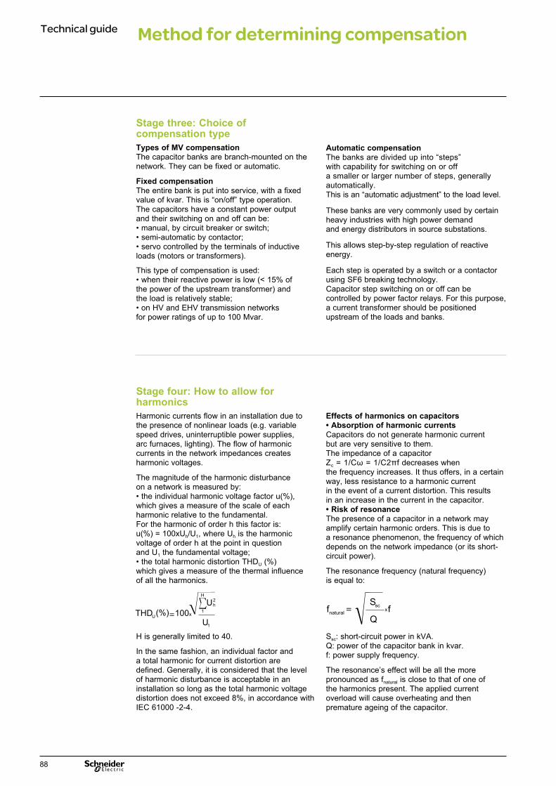
Technical guide Method for determining compensation
Stage three: Choice of compensation type Types of MV compensationThe capacitor banks are branch-mounted on the network. They can be fixed or automatic.
Fixed compensationThe entire bank is put into service, with a fixed value of kvar. This is “on/off” type operation.The capacitors have a constant power output and their switching on and off can be:• manual, by circuit breaker or switch;• semi-automatic by contactor;• servo controlled by the terminals of inductive loads (motors or transformers).
This type of compensation is used:• when their reactive power is low (< 15% of the power of the upstream transformer) and the load is relatively stable;• on HV and EHV transmission networks for power ratings of up to 100 Mvar.
Automatic compensationThe banks are divided up into “steps” with capability for switching on or off a smaller or larger number of steps, generally automatically. This is an “automatic adjustment” to the load level.
These banks are very commonly used by certain heavy industries with high power demand and energy distributors in source substations. This allows step-by-step regulation of reactive energy.
Each step is operated by a switch or a contactor using SF6 breaking technology. Capacitor step switching on or off can be controlled by power factor relays. For this purpose, a current transformer should be positioned upstream of the loads and banks.
Stage four: How to allow for harmonics Harmonic currents flow in an installation due to the presence of nonlinear loads (e.g. variable speed drives, uninterruptible power supplies, arc furnaces, lighting). The flow of harmonic currents in the network impedances creates harmonic voltages.
The magnitude of the harmonic disturbance on a network is measured by:• the individual harmonic voltage factor u(%), which gives a measure of the scale of each harmonic relative to the fundamental.For the harmonic of order h this factor is: u(%) = 100xUh/U1, where Uh is the harmonic voltage of order h at the point in question and U1 the fundamental voltage;• the total harmonic distortion THDU (%) which gives a measure of the thermal influence of all the harmonics.
H is generally limited to 40.
In the same fashion, an individual factor and a total harmonic for current distortion are defined. Generally, it is considered that the level of harmonic disturbance is acceptable in an installation so long as the total harmonic voltage distortion does not exceed 8%, in accordance with IEC 61000 -2-4.
Effects of harmonics on capacitors• Absorption of harmonic currents Capacitors do not generate harmonic current but are very sensitive to them.The impedance of a capacitorZc = 1/Cω = 1/C2πf decreases when the frequency increases. It thus offers, in a certain way, less resistance to a harmonic current in the event of a current distortion. This results in an increase in the current in the capacitor.• Risk of resonanceThe presence of a capacitor in a network may amplify certain harmonic orders. This is due to a resonance phenomenon, the frequency of which depends on the network impedance (or its short-circuit power).
The resonance frequency (natural frequency) is equal to:
Ssc: short-circuit power in kVA.Q: power of the capacitor bank in kvar.f: power supply frequency.
The resonance’s effect will be all the more pronounced as fnatural is close to that of one of the harmonics present. The applied current overload will cause overheating and then premature ageing of the capacitor.
THD 100xU(%)=
U1
U2h
1
H
fnatural
=Q
Sscfx
88
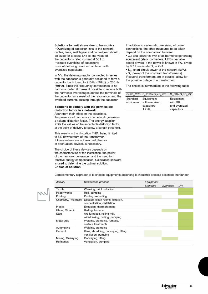
Solutions to limit stress due to harmonics• Oversizing of capacitor links to the network: cables, lines, switchgear and controlgear should be sized for at least 1.43 Ic, the value of the capacitor’s rated current at 50 Hz;• voltage oversizing of capacitors;• use of detuning reactors combined with oversized capacitors.
In MV, the detuning reactor connected in series with the capacitor is generally designed to form a capacitor bank tuned to 215 Hz (50 Hz) or 260 Hz (60 Hz). Since this frequency corresponds to no harmonic order, it makes it possible to reduce both the harmonic overvoltages across the terminals of the capacitor as a result of the resonance, and the overload currents passing through the capacitor. Solutions to comply with the permissible distortion factor in a networkApart from their effect on the capacitors, the presence of harmonics in a network generates a voltage distortion factor. The energy supplier limits the values of the acceptable distortion factor at the point of delivery to below a certain threshold.
This results in the distortion THDU being limited to 5% downstream of the transformer.If these values are not reached, the use of attenuation devices is necessary.
The choice of these devices depends on the characteristics of the installation, the power of the harmonic generators, and the need for reactive energy compensation. Calculation software is used to determine the optimal solution.Choice of solution
In addition to systematic oversizing of power connections, the other measures to be taken depend on the comparison between:• Gh: total power in kVA of all harmonic generating equipment (static converters, UPSs, variable speed drives). If the power is known in kW, divide by 0.7 to estimate Gh in kVA.• Ssc: short-circuit power of the network (kVA).• Sn: power of the upstream transformer(s). If several transformers are in parallel, allow for the possible outage of a transformer.
The choice is summarized in the following table.
Gh ≤ Scc / 120 Scc / 120 < Gh < Scc / 70 Scc / 70 < Gh ≤ Scc / 30 Standard Equipement Equipement equipment with oversized with DR capacitors and oversized 1.2 x UN capacitors
Complementary approach is to choose equipments according to industrial process described hereunder:
Activity Businesses process Equipment Standard Oversized DRTextile Weaving, print inductionPaper-works Roll, pumpingPrinting Printing, recordingChemistry, Pharmacy Dosage, clean rooms, filtration, concentration, distillationPlastic Extrusion, thermoformingGlass, Céramic Rolling, furnaceSteel Arc furnaces, rolling mill, wiredrawing, cutting, pumpingMetallurgy Welding, stamping, furnace, surface treatmentsAutomotive Welding, stampingCement Kilns, shredding, conveying, lifting, ventilation, pumpingMining, Quarrying Conveying, liftingRefineries Ventilation, pumping
89

Technical guide
General characteristics of switchgear and controlgear The equipment used is defined by the following selection criteria:• rated voltage and current;• making current;• capacitive breaking capacity;• making capacity;• number of operations.
Precautions should be taken concerning:• The capacitive breaking capacity (kA rms).The problem is due to the existence, after switching off, of a restriking voltage equal to the difference between the mains voltage and the charging voltage of the capacitors. The device must be capable of preventing this restriking.• The making capacity (kA peak) which must be able to withstand inrush currents.
Type of switchgear and controlgear The choice of switchgear and controlgear depends on electrical criteria but in particular on the type of use of the banks. There are several possibilities:• Disconnector. Without breaking capacity, it will be used only for operation of the bank with the power off. It requires the use of a protection device (fuse or circuit breaker).• Switch. It has only a breaking capacity limited to IN and a moderate making capacity, and does not allow a large number of operations. Therefore, it will be used especially in the case of so-called fixed banks.• Contactor. This allows a very large number of operations, but is limited to 12 kV. It can be coordinated with fuses of "High Rupturing Capacity" (HRC).• Circuit breaker. This very efficient device will be used for general protection of high-power banks.
Switching ON capacitor banks Switching on a bank Qc (fixed or stepped) is accompanied by transient current and voltage conditions. A making overcurrent of short duration (≤ 10 ms) appears. Its peak value and its frequency, generally high, depend on the characteristics of the upstream network and the number of banks. Where necessary, a surge reactor may or may not have to be inserted to limit this overcurrent to the peak resistance of the capacitors, namely: Imax. peak ≤100 IN, (IN: rated current of bank Qc) or to a lower value if the switchgear has limited characteristics.
In the case of a single bank, the overcurrent is generally from 10 to 30 IN, but for a high Scc and low Qc it may exceed the limit and require an inrush reactor. In the case of banks in parallel, either identical (regulated system) or of different values (compensation of several motors), the overcurrent will be very high and will have to be limited. In making this choice, allow for the number of possible operations under the given current.
Control of capacitor banks
90

Example 1: Fixed bank of 250 kvar at a phase-to-phase voltage of U = 5.5 kV powered by a network of maximum short-circuit power Ssc = 250 MVA.L0 = 386 μH.C = 26.3 μF.Icapa = 26.2 A.Ie = 1173 A.fe = 1581 Hz.
Example 2: Bank of 3 steps each of 350 kvar at a phase-to-phase voltage of U = 5.5 kV at a distance of 5 m from their associated cutoff device.C = 36,8 μF.Icapa = 36.7 A. ● without inrush reactorl = 2,5 μH.Ie = 11490 A !!fe = 16.5 kHz.● inrush limiting reactor L is mandatory in order to limit Ie to a value lower than 100 Icapa either:L = 50 μH.Ie = 2508 A.fe = 3619 Hz.
Switching ON capacitor banks, synthesis
* Imax. peak is the smaller of the following 2 making values:• maximum peak current of the bank (i.e. 100xIcapa)• maximum peak current of the switchgear Imaking max.Note: For steps not having the same powers, please contact us
Fixed bank Stepped bank (identical)
Lo = S/C inductance of the network n steps switched on when Scc = √3 U Icc with U/√3 = LoωIcc n+1 is switched on l = link inductance (0.5 µH/m)Bank power Q = U2Cω = √3UIcapa Q = U2Cω = √3UIcapa ; Q = Power of each step
Peak making current
Natural frequency
Q-factor, 2 (n+2)/(n+1)mainsQ-factor, 2 2n/(n+1)bankInrush reactor Generally, no need of an inrush Generally, need of an inrush reactor reactor (unless high Ssc and low Q)
Calculation inrush reactor
L (μH) - Q (Mvar) - Ssc (MVA) L (μH) - Q (Mvar) - Ssc (MVA) I max. peak (kA)* Imax. peak (kA)*
Lo
CU√3
C CC
l ll
1 n+12
DE
9009
3 DE
9009
3
I1 x
ωcapa
Ie =
L Co
1 x 2 xI Ue =
U1
x x
U2h
1
H
2
3
C
l
n
n+1
xIcapa
Ie = 2 S
cc
Q
1fe =2π L Co
ω
L ≥
U1
10 x
U2h
1
H
2Q U
I3max peak
Scc
2
2
fnaturalII
capa
fnetwork
e = xxn
n+1
2 x
1fe =2π lC
ω
L ≥
U1
2.10
3
x x
U2h
1
H
Q6 2
x 1
Imax peak
2
n
n+1
91

Technical guide Control of capacitor banks
Switching OFF capacitor banks A capacitor is switched off by a cutoff device precisely at zero crossing of the current, which coincides with the instantaneous maximum voltage.On the one hand, a voltage surge escalation3 U, 5 U may occur if the device does not have fast dielectric restoration; this was the case for air cutoff devices; this phenomenon has disappeared with SF6 devices. On the other hand, the capacitor remains charged at its maximum voltage. In the event of fast reclosing, an increased transient phenomenon will occur.The IEC 60871 standard requires a capacitor discharge device so that the voltage across the terminals does not exceed 75 V, 10 minutes after disconnection.A quick discharge can be obtained using discharge reactors; however, this system has a limit set of 3 consecutive discharges followed by a rest period of 2 hours, due to reactor overheating. This will have to be carefully evaluated when using banks having regular switchings.
Switchgear used for capacitor control Switches are chosen for banks with a low rate of operations (at most 2 operations per day); above this, contactors are used.For the most powerful banks (connected in double star), the SF6 switch or circuit breaker is the most appropriate device. All switchgear and controlgear should be sized for 1.43 times the rated current of the capacitor bank.The switched capacitive current values given by the manufacturer should be complied with (see table below).
Medium voltage switchgear characteristics
Switchgear designation Short circuit performance Rated normal current Capacitive current switched SF1 25kA/36kV 630 and 1250A 440 and 880ASF2 40kA/40.5kV 630 and 3150A 440 and 2200Acontactor Rollarc R 400 10kA/7.2kV 400A 240A 8kA/12kV
92

Technical guide Protection and circuit diagrams of capacitor banks
Capacitors The capacitor is a reliable component if it is used in the conditions for which it has been designed and manufactured. It is formed of elements placed in series to resist voltage, and placed in parallel to obtain the wanted capacitance. There are two types of capacitor at present: with or without internal fuses.
Capacitors wit-hout internal fuses Capacitor failure is the result of failure of an internal element. A fault in an element results in short-circuiting of a unit in series and hence a rise in the voltage on the other units in series. Having no protection device inside the capacitor, the fault will be elimina-ted only by cutoff of the bank or separation of the circuit in the defective capacitor.
Capacitors with internal fusesEach element is protected by a fuse. In this case, any fault in an element will be eliminated. The defective circuit will be isolated. The result will be a slight capacitance variation and the voltage will be distributed over the sound elements in series. The setting of the unbalance relay shall be such that the loss of elements of a given unit in series causes switching off of the bank when the resulting overvoltage exceeds the limits determined by the standard (IEC 60871). Protection by internal fuses increases the availability of capa-citor banks, because the loss of one element does not systematically result in switching off of the bank.
Delta-connected bank This circuit diagram will be used for insulation voltages of 7.2 kV and 12 kV. The maximum power is 900 kvar in three-phase (2 capacitors in parallel). Above this, single-phase capacitors can be used up to 4000 kvar. This type of circuit diagram is highly suitable for MV motor compensation and for automatic total compensation up to 12 kV.
ProtectionOvercurrent protection is provided by HRC fuses.Important note: Choose HRC fuses with a rating of at least 1.7 times the rated current of the bank. In this type of circuit layout, never use capacitors with internal fuses, because the breaking capacity of internal fuses is not designed for network short-circuit currents.
Bank connected in double star For all power ratings, the bank is divided into two stars allowing detection of an unbalance between the two neutrals by an appropriate relay. This type of bank allows the use of capacitors with or without internal fuses. It can be designed for any type of network up to EHV networks. The mounting principle is always the same: to achieve voltage levels of 100 kV or 200 kV, connect a sufficient number of MV capacitors in series. This layout will therefore be used for high powers to be installed, chiefly in fixed banks. However, regulated steps are used by certain power distributors with powers ranging up to 8 Mvar at 36 kV, controlled by a special switch for capacitors.
ProtectionProtection is provided by an unbalance relay detecting a current flowing in the circuit between the two neutrals of the stars. The unbalance current is generally less than 1 A. The setting value will be given after calculation for each bank. The setting threshold is given by the manufacturer. It depends on the internal structure of the bank (series and parallel combination of capacitor units) and on whether or not internal fuses for capacitor protection are present.The time delay is approximately several tenths of a second. In addition to this protection, provision should be made for overload protection on each phase. The value shall be set to 1.43 times the rated current of the bank.
Double star connected capacitor bank
Delta connected capacitor bank
DE
9009
4
DE
9009
5
93
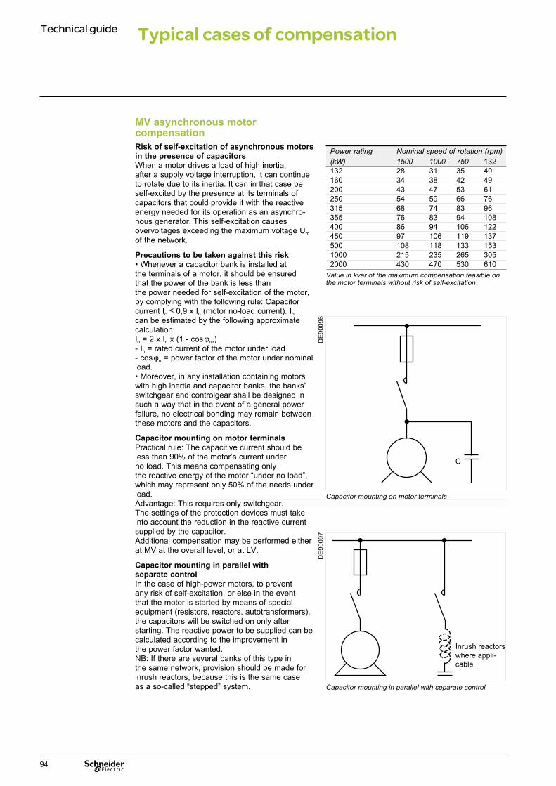
Technical guide Typical cases of compensation
MV asynchronous motor compensation Risk of self-excitation of asynchronous motors in the presence of capacitorsWhen a motor drives a load of high inertia, after a supply voltage interruption, it can continue to rotate due to its inertia. It can in that case be self-excited by the presence at its terminals of capacitors that could provide it with the reactive energy needed for its operation as an asynchro-nous generator. This self-excitation causes overvoltages exceeding the maximum voltage Um of the network.
Precautions to be taken against this risk• Whenever a capacitor bank is installed at the terminals of a motor, it should be ensured that the power of the bank is less than the power needed for self-excitation of the motor, by complying with the following rule: Capacitor current Ic ≤ 0,9 x Io (motor no-load current). Io can be estimated by the following approximate calculation: Io = 2 x In x (1 - cos φn,)- In = rated current of the motor under load- cos φn = power factor of the motor under nominal load.• Moreover, in any installation containing motors with high inertia and capacitor banks, the banks’ switchgear and controlgear shall be designed in such a way that in the event of a general power failure, no electrical bonding may remain between these motors and the capacitors.
Capacitor mounting on motor terminalsPractical rule: The capacitive current should be less than 90% of the motor’s current under no load. This means compensating only the reactive energy of the motor “under no load”, which may represent only 50% of the needs under load.Advantage: This requires only switchgear. The settings of the protection devices must take into account the reduction in the reactive current supplied by the capacitor.Additional compensation may be performed either at MV at the overall level, or at LV.
Capacitor mounting in parallel with separate controlIn the case of high-power motors, to prevent any risk of self-excitation, or else in the event that the motor is started by means of special equipment (resistors, reactors, autotransformers), the capacitors will be switched on only after starting. The reactive power to be supplied can be calculated according to the improvement in the power factor wanted.NB: If there are several banks of this type in the same network, provision should be made for inrush reactors, because this is the same case as a so-called “stepped” system.
Power rating Nominal speed of rotation (rpm) (kW) 1500 1000 750 132 132 28 31 35 40160 34 38 42 49 200 43 47 53 61 250 54 59 66 76 315 68 74 83 96 355 76 83 94 108 400 86 94 106 122 450 97 106 119 137 500 108 118 133 153 1000 215 235 265 305 2000 430 470 530 610
C
Inrush reactors where appli-cable
Capacitor mounting on motor terminals
DE
9009
6
Capacitor mounting in parallel with separate control
DE
9009
7
Value in kvar of the maximum compensation feasible on the motor terminals without risk of self-excitation
94

MV transformer compensation The power rating of a transformer is given as apparent power (kVA). The greater tg φ (or the smaller cos φ), the lower the active power available for a transformer. The transformer and the installation are therefore poorly optimized.
The connection of capacitors to the MV terminals of the transformer therefore offers two advantages:• Compensate magnetic losses and relieve the upstream installation. This is extremely interesting, because the transformer generally stays energized permanently.For the reactive power values to be compensated, see table below.• Increase the active power available on the transformer secondary. It is worthwhile, in the event of a current or future extension, improving the power factor and thus avoiding investment in a new transformer.
Apparent power Primary voltage Secondary voltage Short-circuit Reactive power (MVA) (kV) (kV) voltage to be compensated Usc (%) unloaded (kvar) 2.5 20 3 to 16 6.5 40 30 3 to 16 6.5 503.15 20 3 to 16 7 50 30 3 to 16 7 604 20 3 to 16 7 60 30 3 to 16 7 705 20 3 to 16 7.5 70 30 3 to 16 7.5 806.3 10 to 36 3 to 20 8.1 708 10 to 36 3 to 20 8.4 8010 10 to 36 3 to 20 8.9 9012.5 10 to 36 3 to 20 9.4 12016 10 to 36 3 to 20 10.1 13020 10 to 36 3 to 20 11 14025 10 to 36 3 to 20 12.1 17531.5 10 to 36 3 to 20 13.5 19040 10 to 36 3 to 20 15.3 240
95

Technical guide Capacitor definitions and terminology
Scope of applicationThe standards (IEC 60871) apply to capacitor units and capacitor banks designed in particular to be used to correct the power factor of alternating-current networks having a rated voltage greater than or equal to 1000 V, of frequency equal to 16 2/3 , 50 or 60 Hz.
Capacitor element Device consisting basically of two electrodes separated by a dielectric.
Capacitor unitSet of one or more capacitor elements placed in the same enclosure and connected to output terminals.
Capacitor bank Set of capacitor units connected so as to act jointly.
Internal protection of a capacitor Fuse mounted inside a unit and con-nected in series with an element or a group of elements.
Capacitor discharge device Device that can be incorporated in the capacitor and is capable, in a specified time, of reducing practically to zero the voltage between the capacitor terminals when the capacitor has been disconnected from the network.
Rated capacitance (Cn)Value of the capacitance for which the capacitor was designed.
Rated power of a capacitor (Qn) Reactive power output at rated values:capacitance, frequency and voltage (or current).
Rated voltage of a capacitor (Un) Rms value of the alternating voltage for which the capacitor was designed.
Rated frequency of a capacitor (Fn) Frequency for which the capacitor was designed.
Rated current of a capacitor (In)Rms value of an alternating current for which the capacitor was designed.
Residual voltageVoltage which remains on the terminals of a capacitor for some time after its disconnection.
Highest network voltage (Um) The highest value of the phase-to-phase rms voltage which may occur at any time and any point on the network in normal operating conditions.This value does not take into account temporary voltage fluctuations due to faults or sudden tripping causing the separation of major loads.
Highest voltage for the equipment The highest voltage for which the equipment of a network is specified with regard to its insulation in particular. This voltage must be at least equal to the highest voltage of the network for which the equipment is intended.
Insulation levelThe insulation level of an equipment is defined, in the present situation, as the expression of the values of its impulse withstand voltage and its power-frequency withstand voltage.
96

Technical guide
97

Make the most of your energy™
www.schneider-electric.com* Tirez le meilleur partie de votre énergie
07-2013CFIED 205098EN
Schneider Electric Industries SAS
© 2
013
- Sch
neid
er E
lect
ric -
All
right
s re
serv
ed
As standards, specifications and designs change from time to time, please ask for confirmation of the information given in this publication.
Publication: Schneider Electric Industries SASPhotos: Schneider ElectricPrinted:
35, rue Joseph MonierCS 3032392506 Rueil Malmaison Cedex France
RCS Nanterre 954 503 439Capital social 896 313 776 €www.schneider-electric.com
10-31-1247
This document has been printed on ecological paper.
Schneider Electric Industries SAS
10-31-1247


