24
POWER FACTOR CORRECTION
POWER FACTOR CORRECTION

ContentsGeneral
information

Power factor correction 4-9General information
The Alpx³ range
The Alpx³ range
Catalogue pages
Dimension details 20-23
Capacitors / Reactors / Power factor controller / 10-15 Contactor for capacitor switching
Technical specification 16-19
CATALOGUE 3GENERAL CONTENTS

POWER FACTORBy definition, the power factor of an electrical installation (PF) is equal to the active power P (kW) over the apparent power S (kVA).
Usually PF - Cos ø
A power factor of 1 will result in no reactive energy consumption and vice versa.Energy metering devices record active and reactive energy consumption. Electricity suppliers generally use the term tg ø on their bills.
ADVANTAGESBy supplying reactive energy on demand, ALPX³ capacitor banks allow the subscriber to do the following:
1. Increase the power available to the distribution transformers
For a 1000 kVAr transformer with cos ø = 0.75 and a 750 kW installation: by increasing the cos ø to 0.96 a further 210 kW can be gained (+28%).
Correlation between power factor/gain in available power
2. Limit energy losses in the cables by the Joule effet (limiting voltage drops) given the decrease in the current carried in the installation
For a 1000 kVA transformer with cos ø =0.75and a 750 kW installation: by increasing the cos ø to 0.96, we get a reduction in current of around 22%.
3. Achieve energy savings regardless of the type of electricity supplier contract.• Installing a capacitor bank allows users to:- save energy- avoid the penalties applied by the electricity
supplier or- optimise the electricity contract
An AC electrical installation incorporating receivers such as transformers, motors, fluorescent tube ballasts or any other receivers whose current is phase-shifted in relation to the voltage, consumes reactive energy.
This reactive energy (expressed in kilovar-hours – kVArh) is billed in the same way as active energy by energy suppliers. Reactive energy therefore results in more power being used and thus contributes to higher electricity bills.
POWER FACTOR CORRECTION
a good power factor is:- high cos ø (close to 1) - or low tg ø (close to 0)
PF = P (kW)/S(kVA)
Cos ϕ and tg ϕ are linked by the following equation:
Level of power factor cos ø
Additional power available to the transformer
0.8 +7%
0.85 +13%
0.9 +20%
0.96 +28%
1 +33%
EXAMPLE
EXAMPLE
11 + (tg ø)2Cos ø =
4
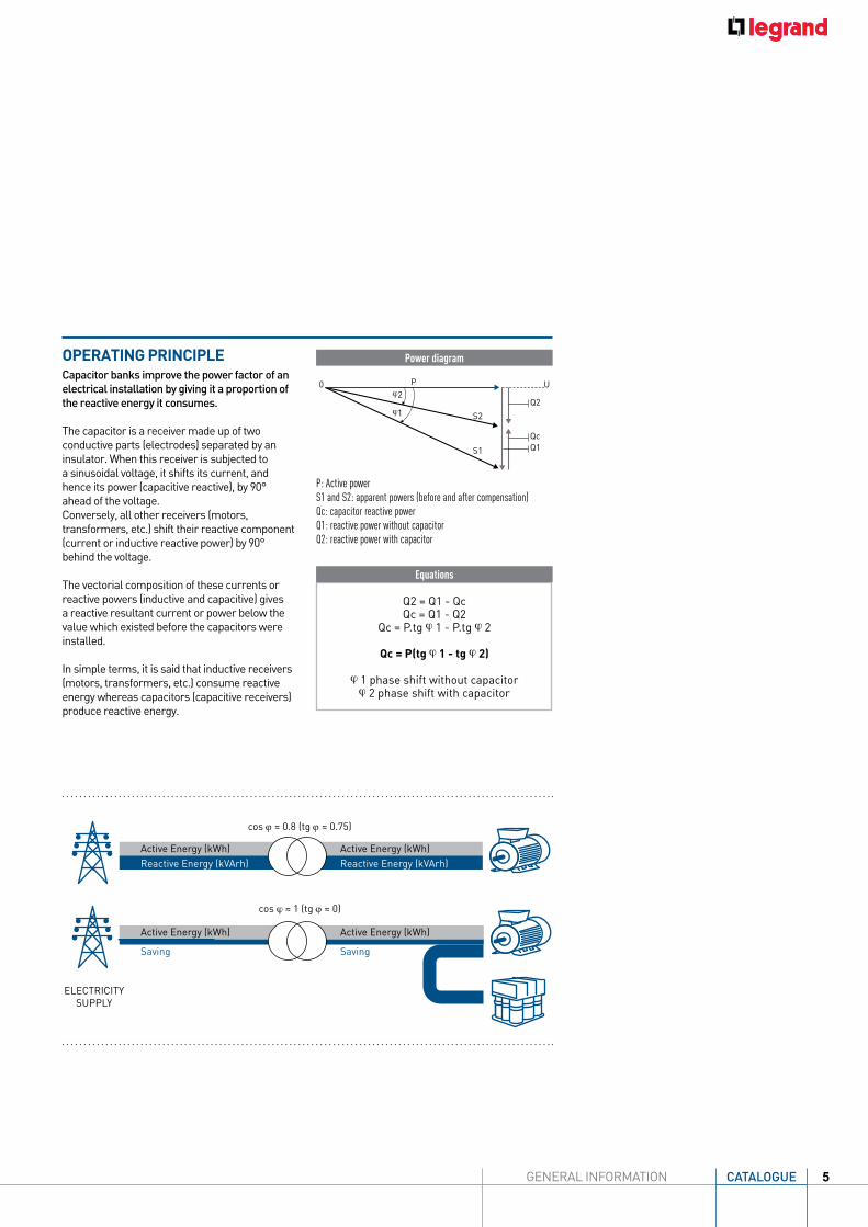
OPERATING PRINCIPLECapacitor banks improve the power factor of an electrical installation by giving it a proportion of the reactive energy it consumes.
The capacitor is a receiver made up of two conductive parts (electrodes) separated by an insulator. When this receiver is subjected to a sinusoidal voltage, it shifts its current, and hence its power (capacitive reactive), by 90° ahead of the voltage.Conversely, all other receivers (motors, transformers, etc.) shift their reactive component (current or inductive reactive power) by 90° behind the voltage.
The vectorial composition of these currents or reactive powers (inductive and capacitive) gives a reactive resultant current or power below the value which existed before the capacitors were installed.
In simple terms, it is said that inductive receivers (motors, transformers, etc.) consume reactive energy whereas capacitors (capacitive receivers) produce reactive energy.
Active Energy (kWh)
ELECTRICITY SUPPLY
cos ϕ ≈ 0.8 (tg ϕ ≈ 0.75)
cos ϕ ≈ 1 (tg ϕ ≈ 0)
Active Energy (kWh)Reactive Energy (kVArh) Reactive Energy (kVArh)
Active Energy (kWh) Active Energy (kWh)
Saving Saving
Q2 = Q1 - QcQc = Q1 - Q2
Qc = P.tg ø 1 - P.tg ø 2
Qc = P(tg ø 1 - tg ø 2)
ø 1 phase shift without capacitorø 2 phase shift with capacitor
Equations
Power diagram
P: Active powerS1 and S2: apparent powers (before and after compensation)Qc: capacitor reactive powerQ1: reactive power without capacitorQ2: reactive power with capacitor
P
S2
S1
0ø2
ø1
Q1
Q2
Qc
U
CATALOGUE 5GENERAL INFORMATION

EXAMPLE
In a low voltage electrical installation, determining the power factor correction solution requires several stages as follows:
Determining the capacitor power (kVAr) to compensate for the reactive energy required for the installation
Determining the general configuration
Determining the compensationmode
Determining the capacitor bank type according to the level of harmonics
Fixed compensation for stable load Automatic compensation for variable or unstable load Dynamic compensation for very unstable load
Global compensation for the whole installation Compensation for each sector Individual compensation in high power loads
Identify the level of harmonic pollution by THDi –THDu measurements or if necessary (eg: new installation) by estimating the percentage of "non-linear loads" (SH/ST)
DETERMINING THE CAPACITOR POWER IN KVARTo determine the capacitor power (kVAr) to compensate for the reactive energy required for the installation, use one of the following methods:• Measurement of the reactive power and Cos ø
with measurement control units.• Analysis of the electricity supplier's
bills according to the subscription type (subscribed demand, reactive energy billed in kVArh and tg ø).
• In the context of future installations, compensation is frequently required right from the commissioning stage. In this case, it is not possible to calculate the capacitor bank using conventional methods (electricity bill).
For this type of installation, we recommend installing a capacitor bank with approximately 25% of the nominal power of the corresponding HV/LV transformer.
1000 kVA transformer, capacitor Q = 250 kVArNB: This type of ratio corresponds to the following operating conditions:- 1000 kVA transformer- Actual transformer load = 75%- Cos ø of the load = 0.80 } k = 0.421 - Cos ø to be obtained = 0.95 } (see table on opposite page)
• Estimated total amount of reactive energy needed for all receivers in the installation, especially motors and transformers depending on the manufacturer's data.
Qc = 1000 x 75% x 0.80 x 0.421 = 250 kvar
STEP
1ST
EP 2
STEP
3ST
EP 4
STEP 1
DETERMINING THE LV POWER FACTOR CORRECTION SOLUTION
6
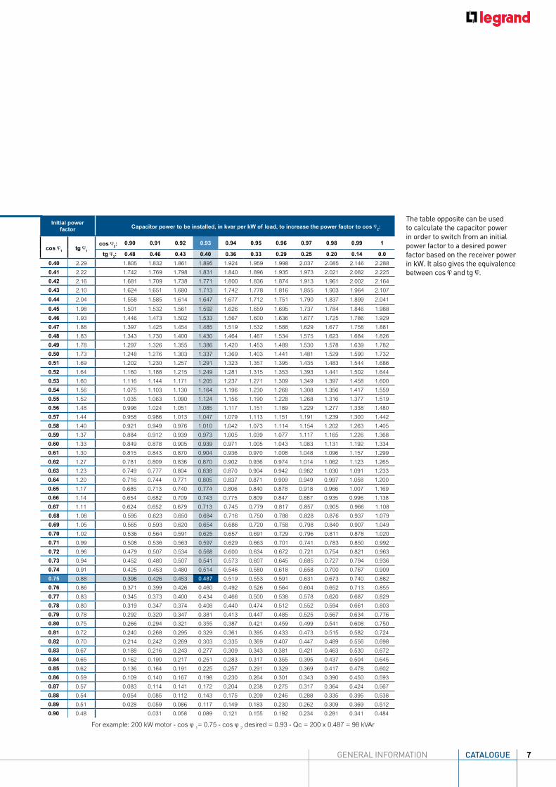
The table opposite can be used to calculate the capacitor power in order to switch from an initial power factor to a desired power factor based on the receiver power in kW. It also gives the equivalence between cos ø and tg ø.
Initial power factor Capacitor power to be installed, in kvar per kW of load, to increase the power factor to cos ø2:
cos ø1 tg ø1 cos ø2: 0.90 0.91 0.92 0.93 0.94 0.95 0.96 0.97 0.98 0.99 1
tg ø2: 0.48 0.46 0.43 0.40 0.36 0.33 0.29 0.25 0.20 0.14 0.0
0.40 2.29 1.805 1.832 1.861 1.895 1.924 1.959 1.998 2.037 2.085 2.146 2.288
0.41 2.22 1.742 1.769 1.798 1.831 1.840 1.896 1.935 1.973 2.021 2.082 2.225
0.42 2.16 1.681 1.709 1.738 1.771 1.800 1.836 1.874 1.913 1.961 2.002 2.164
0.43 2.10 1.624 1.651 1.680 1.713 1.742 1.778 1.816 1.855 1.903 1.964 2.107
0.44 2.04 1.558 1.585 1.614 1.647 1.677 1.712 1.751 1.790 1.837 1.899 2.041
0.45 1.98 1.501 1.532 1.561 1.592 1.626 1.659 1.695 1.737 1.784 1.846 1.988
0.46 1.93 1.446 1.473 1.502 1.533 1.567 1.600 1.636 1.677 1.725 1.786 1.929
0.47 1.88 1.397 1.425 1.454 1.485 1.519 1.532 1.588 1.629 1.677 1.758 1.881
0.48 1.83 1.343 1.730 1.400 1.430 1.464 1.467 1.534 1.575 1.623 1.684 1.826
0.49 1.78 1.297 1.326 1.355 1.386 1.420 1.453 1.489 1.530 1.578 1.639 1.782
0.50 1.73 1.248 1.276 1.303 1.337 1.369 1.403 1.441 1.481 1.529 1.590 1.732
0.51 1.69 1.202 1.230 1.257 1.291 1.323 1.357 1.395 1.435 1.483 1.544 1.686
0.52 1.64 1.160 1.188 1.215 1.249 1.281 1.315 1.353 1.393 1.441 1.502 1.644
0.53 1.60 1.116 1.144 1.171 1.205 1.237 1.271 1.309 1.349 1.397 1.458 1.600
0.54 1.56 1.075 1.103 1.130 1.164 1.196 1.230 1.268 1.308 1.356 1.417 1.559
0.55 1.52 1.035 1.063 1.090 1.124 1.156 1.190 1.228 1.268 1.316 1.377 1.519
0.56 1.48 0.996 1.024 1.051 1.085 1.117 1.151 1.189 1.229 1.277 1.338 1.480
0.57 1.44 0.958 0.986 1.013 1.047 1.079 1.113 1.151 1.191 1.239 1.300 1.442
0.58 1.40 0.921 0.949 0.976 1.010 1.042 1.073 1.114 1.154 1.202 1.263 1.405
0.59 1.37 0.884 0.912 0.939 0.973 1.005 1.039 1.077 1.117 1.165 1.226 1.368
0.60 1.33 0.849 0.878 0.905 0.939 0.971 1.005 1.043 1.083 1.131 1.192 1.334
0.61 1.30 0.815 0.843 0.870 0.904 0.936 0.970 1.008 1.048 1.096 1.157 1.299
0.62 1.27 0.781 0.809 0.836 0.870 0.902 0.936 0.974 1.014 1.062 1.123 1.265
0.63 1.23 0.749 0.777 0.804 0.838 0.870 0.904 0.942 0.982 1.030 1.091 1.233
0.64 1.20 0.716 0.744 0.771 0.805 0.837 0.871 0.909 0.949 0.997 1.058 1.200
0.65 1.17 0.685 0.713 0.740 0.774 0.806 0.840 0.878 0.918 0.966 1.007 1.169
0.66 1.14 0.654 0.682 0.709 0.743 0.775 0.809 0.847 0.887 0.935 0.996 1.138
0.67 1.11 0.624 0.652 0.679 0.713 0.745 0.779 0.817 0.857 0.905 0.966 1.108
0.68 1.08 0.595 0.623 0.650 0.684 0.716 0.750 0.788 0.828 0.876 0.937 1.079
0.69 1.05 0.565 0.593 0.620 0.654 0.686 0.720 0.758 0.798 0.840 0.907 1.049
0.70 1.02 0.536 0.564 0.591 0.625 0.657 0.691 0.729 0.796 0.811 0.878 1.020
0.71 0.99 0.508 0.536 0.563 0.597 0.629 0.663 0.701 0.741 0.783 0.850 0.992
0.72 0.96 0.479 0.507 0.534 0.568 0.600 0.634 0.672 0.721 0.754 0.821 0.963
0.73 0.94 0.452 0.480 0.507 0.541 0.573 0.607 0.645 0.685 0.727 0.794 0.936
0.74 0.91 0.425 0.453 0.480 0.514 0.546 0.580 0.618 0.658 0.700 0.767 0.909
0.75 0.88 0.398 0.426 0.453 0.487 0.519 0.553 0.591 0.631 0.673 0.740 0.882
0.76 0.86 0.371 0.399 0.426 0.460 0.492 0.526 0.564 0.604 0.652 0.713 0.855
0.77 0.83 0.345 0.373 0.400 0.434 0.466 0.500 0.538 0.578 0.620 0.687 0.829
0.78 0.80 0.319 0.347 0.374 0.408 0.440 0.474 0.512 0.552 0.594 0.661 0.803
0.79 0.78 0.292 0.320 0.347 0.381 0.413 0.447 0.485 0.525 0.567 0.634 0.776
0.80 0.75 0.266 0.294 0.321 0.355 0.387 0.421 0.459 0.499 0.541 0.608 0.750
0.81 0.72 0.240 0.268 0.295 0.329 0.361 0.395 0.433 0.473 0.515 0.582 0.724
0.82 0.70 0.214 0.242 0.269 0.303 0.335 0.369 0.407 0.447 0.489 0.556 0.698
0.83 0.67 0.188 0.216 0.243 0.277 0.309 0.343 0.381 0.421 0.463 0.530 0.672
0.84 0.65 0.162 0.190 0.217 0.251 0.283 0.317 0.355 0.395 0.437 0.504 0.645
0.85 0.62 0.136 0.164 0.191 0.225 0.257 0.291 0.329 0.369 0.417 0.478 0.602
0.86 0.59 0.109 0.140 0.167 0.198 0.230 0.264 0.301 0.343 0.390 0.450 0.593
0.87 0.57 0.083 0.114 0.141 0.172 0.204 0.238 0.275 0.317 0.364 0.424 0.567
0.88 0.54 0.054 0.085 0.112 0.143 0.175 0.209 0.246 0.288 0.335 0.395 0.538
0.89 0.51 0.028 0.059 0.086 0.117 0.149 0.183 0.230 0.262 0.309 0.369 0.512
0.90 0.48 0.031 0.058 0.089 0.121 0.155 0.192 0.234 0.281 0.341 0.484
For example: 200 kW motor - cos ø 1= 0.75 - cos ø 2
desired = 0.93 - Qc = 200 x 0.487 = 98 kVAr
CATALOGUE 7GENERAL INFORMATION

DETERMINING THE GENERAL CONFIGURATIONDepending on the installation architecture, the location and power of the receivers consuming reactive energy, the following are possible:
GLOBAL COMPENSATION in the main LV distribution board > choose an automatic or dynamic bank
COMPENSATION BY EACH SECTOR in the secondary distribution boards, for example: workshop secondary distribution board > choose an automatic or dynamic bank
INDIVIDUAL COMPENSATION as close as possible to the load consuming the reactive energy (depending on variation in the loads a fixed bank,
Compensating reactive energy at the terminals of a motor by a fixed capacitor bank controlled at the same time as the motor
DETERMINING THE COMPENSATION MODE
Transformer
Electricity supply
Circuit breaker
GC
GC = Global compensationCS = Compensation by sectorIC = Individual compensationM = Typical motor load
CS
IC IC IC
CS
MA
MA
MA
MA
GLOBAL COMPENSATION COMPENSATION BY EACH SECTOR
INDIVIDUAL COMPENSATION
ADVA
NTA
GES
No billing of reactive energy Increased power available
at the transformer secondary Most economical solution
No billing of reactive energy Reduction of losses along
the line between transformer and mains secondary distribution boards Economical solution
No billing of reactive energy Reduction of losses along
the whole line between transformer and the load Power factor correction
as close as possible to the devices consuming reactive energy
CO
MM
ENTS
No reduction in losses along the line (voltage dips for loads a long way from the capacitor bank) No savings in terms of
sizing electrical equipment
Solution generally used for very extensive factory networks
Most expensive solution given the high number of installations
EXAMPLE
STEP 2 STEP 3
DETERMINING THE POWER FACTOR CORRECTION SOLUTION (continued)
STAB
LE L
OAD
VARI
ABLE
LOA
D
RAPI
DLY
CHAN
GIN
G LO
AD
QcST
> 15%< 15%
Fixed Automatic Dynamic
QC = Power of the compensation system in kVar
ST = Power of the MV/LV transformer in kVA (or MV/LV transformers if there are two or more transformers in parallel)
8

DETERMINING THE CAPACITOR BANK TYPE ACCORDING TO THE LEVEL OF HARMONICSFor supplies with a high level of harmonic pollution, Legrand recommends capacitor banks with detuned reactors.
The detuned reactor performs a threefold role:• Increasing the capacitor impedance in relation to the harmonic currents• Shifting the parallel resonance frequency (Fr.p) of the source and capacitor to below the main
frequencies of the harmonic currents that are causing interference.
Tuning frequency
(Hz)
Blocking factor(P%)
Tuning number
(n)189 7 3.78135 14 2.7
• Helping to reduce harmonic levels in the supply.
The table opposite can be used to select the capacitor bank type according to the degree of harmonic pollution, by measuring the percentage of THDi and THDu or by estimating the percentage total power of SH/ST non-linear loads.
Measurements Estimates Type of capacitor to be used Reactor to be used
THDU % THDI % SH/ST %
≤ 3 ≤ 10 ≤ 15 Standard Duty -
≤ 4 ≤ 15 ≤ 25 Heavy Duty -
≤ 6 ≤ 30 ≤ 35 Standard Duty 7% Reactor
*14% Reactor if high level of 3rd order harmonics
≤ 8 ≤ 40 ≤ 50 Heavy Duty 7% Reactor
STEP 4
SH (kVA) is the weighted total power of the harmonic generators present at the transformer secondary.
ST (kVA) is the power rating of the HV/LV transformer.
THDi = Total Harmonic Distortion (THD) is the ratio of the rms value of the harmonic currents In of the order n to the rms value of the fundamental.
THDu = Voltage Distortion (THDu) is caused mainly by the high level of Current Distortion (THDi) and the level of THDu is dependent on the source impedance.
* for example if - • Ih5 > 0.2x145 • Ih3 : 3rd order harmonic currents • Ih5 : 5th order harmonic currents
CATALOGUE 9GENERAL INFORMATION

Alpx³ capacitors
10

FEATURES
SafetyIn the event of thermal or electrical overload, the electrical breakdown occurs. During such event the gases released from di-electric film accumulate in the can. This forms a high pressure inside the can. A specially designed internal mechanism breaks the fuse and the capacitor is disconnected from the circuit. Thus the overpressure dis-connector protects the capacitor.
• Resin filled capacitors - Can type standard duty - Can type Heavy duty - Box type standard duty - Box type heavy duty• Detuned reactor• Controller
The Alpx³ range of capacitors
includes:
11
12
FEATURES
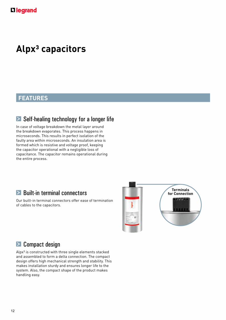
Built-in terminal connectorsOur built-in terminal connectors offer ease of termination of cables to the capacitors.
Compact designAlpx³ is constructed with three single elements stacked and assembled to form a delta connection. The compact design offers high mechanical strength and stability. This makes installation sturdy and ensures longer life to the system. Also, the compact shape of the product makes handling easy.
Terminals for Connection
Alpx³ capacitors
Self-healing technology for a longer lifeIn case of voltage breakdown the metal layer around the breakdown evaporates. This process happens in microseconds. This results in perfect isolation of the faulty area within microseconds. An insulation area is formed which is resistive and voltage proof, keeping the capacitor operational with a negligible loss of capacitance. The capacitor remains operational during the entire process.

Mounting stud
13
FEATURES
Better heat dissipationThe Aluminium can design makes heat dissipation uniform.
Low energy loss (energy saving)Alpx³ is designed and made for long life and low losses during the operation. Thus making it one of the most energy efficient capacitors.
Ease of installationCompact cylindrical design of Alpx³ makes installation easy & faster. The reduced installation time and cost makes a perfect combination for the installer. Mounting is done with a stud at the bottom of the capacitor. The stud forms a solid permanent earthing.
Stable performanceDesign and manufacturing processes make Alpx³ capacitance stable over a long period of time and makes installation error free

14
Conforms to IS 13340-1&2, IEC 60831-1&2ISI markedCompact designSelf healing metallized polypropylene filmOver pressure device for disconnectionLow energy lossesResistance to high temperaturesResin filled
Conforms to IS 13340-1&2, IEC 60831-1&2ISI markedCompact designSelf healing metallized polypropylene filmLow energy lossesResistance to high temperaturesResin filled
Pack Cat.Nos Standard duty 440 VRating
1/12 5150 00 1 kVAr1/12 5150 01 2 kVAr1/12 5150 02 3 kVAr1/12 5150 03 4 kVAr1/12 5150 04 5 kVAr1/6 5150 05 7.5 kVAr1/4 5150 06 10 kVAr1/4 5150 07 12.5 kVAr1/4 5150 08 15 kVAr1/4 5150 09 20 kVAr1/4 5150 10 25 kVAr1/4 5150 11 30 kVAr
Heavy duty 440 VRating
1/12 5150 12 1 kVAr1/12 5150 13 2 kVAr1/12 5150 14 3 kVAr1/12 5150 15 4 kVAr1/6 5150 16 5 kVAr1/4 5150 17 7.5 kVAr1/4 5150 18 10 kVAr1/4 5150 19 12.5 kVAr1/4 5150 20 15 kVAr1/4 5150 21 20 kVAr1/2 5150 22 25 kVAr1/2 5150 23 30 kVAr
Pack Cat.Nos Standard duty 440 VRating
1/4 5150 40 1 kVAr1/4 5150 41 2 kVAr1/4 5150 42 3 kVAr1/4 5150 43 4 kVAr1 5150 44 5 kVAr1 5150 45 7.5 kVAr1 5150 46 8.33 kVAr1 5150 47 10 kVAr1 5150 48 12.5 kVAr1 5150 49 15 kVAr1 5150 50 20 kVAr1 5150 51 25 kVAr1 5150 52 50 kVAr
Heavy duty 440 VRating
1 5150 53 5 kVAr1 5150 54 7.5 kVAr1 5150 55 8.33 kVAr1 5150 56 10 kVAr1 5150 57 12.5 kVAr1 5150 58 15 kVAr1 5150 59 20 kVAr1 5150 60 25 kVAr1 5150 61 50 kVAr
Standard duty 480 VRating
1/6 5150 24 4.2 kVAr1/4 5150 25 6.9 kVAr1/4 5150 26 8.7 kVAr1/4 5150 27 20.4 kVAr1/4 5150 28 14 kVAr1/4 5150 29 17.4 kVAr1/4 5150 30 20.8 kVAr
Standard duty 525 VRating
1/6 5150 31 5 kVAr1/4 5150 32 8.3 kVAr1/4 5150 33 10.4 kVAr1/4 5150 34 12.5 kVAr1/4 5150 35 16.7 kVAr1/4 5150 36 20.8 kVAr1/4 5150 37 25 kVAr
5150 04 5150 06 5150 08
Alpx³ Resin filled box type capacitors
Alpx³Resin filled can type capacitors
5150 23 5150 47 5150 61

15
• Conforms to IS 13340-1993 IEC 60831-1&2• ISI marked• Metalized polypropylene film• Explosion proof design• Better heat dissipation• Low losses• Range: Gas filled - 5 to 25 KVAr
Pack Cat.Nos Heavy duty gas filled capacitor 440 V, 3 phase, 50 Hz
1/4 4151 24 5.2 KVAr1/4 4151 25 7.3 KVAr1/4 4151 26 8.8 KVAr1/4 4151 27 10.5 KVAr1/4 4151 28 12.6 KVAr1/4 4151 29 17.5 KVAr1/4 4151 30 21 KVAr1/4 4151 31 25.2 KVAr
5151 00
Pack Cat.Nos Detuned reactorsHigh harmonic loading capacityLow lossesHigh linearityEasy mountingRating
1 4151 48 Reactor 10 kVAr 7%1 4151 49 Reactor 12.5 kVAr 7%1 4151 50 Reactor 25 kVAr 7%1 4151 51 Reactor 50 kVAr 7%1 4151 52 Reactor 100 kVAr 7%1 4151 53 Reactor 12.5 kVAr 14%1 4151 54 Reactor 25 kVAr 14%1 4151 55 Reactor 50 kVAr 14%
Power factor controller EcoConforms to IEC 61010-1High accuracyIP 41 terminalsManual & Automatic mode of operationFree potential contact for remote alarmDisplays alarm indication for 9 different conditionsRating
1 4151 95 4 Step1 4151 96 6 Step1 4151 97 8 Step1 4151 98 12 Step
4151 95
Reactors and power factor controllerAlpicanTM gas filled capacitors
4151 29

16
FRONT-MOUNTING BLOCKFOR SWITCHING CAPACITORS
FRONT-MOUNTING BLOCK FOR SWITCHING CAPACITORSAuxiliary blocks for switching capacitors are installed directly on CTX³ 3-pole, 9 to 100 A contactors. With their discharge resistors, they reduce current peaks during switching of capacitor banks.
With the wide range of accessories, CTX³ contactors can be used in a wide variety of applications:- Switching capacitor banks - Supply inverter- Reversing contactor- Time-delay motor starter- Control unit on machine, etc.
17
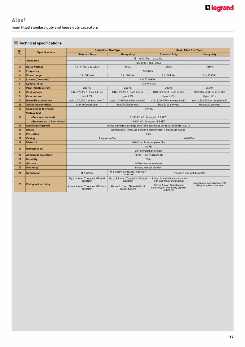
Alpx³resin filled standard duty and heavy duty capacitors
n Technical specifications
Sr. No. Specifications
Resin filled Can Type Resin filled Box Type
Standard Duty Heavy duty Standard Duty Heavy duty
1 StandardsIS 13340 (Part 1&2):2012
IEC 60831-1&2 : 2002
2 Rated Voltage 440 V, 480 V & 525 V 440 V 440 V 440 V
3 Frequency 50/60 Hz
4 Power range 1 to 30 kVAr 1 to 30 kVAr 1 to 50 kVAr 5 to 50 kVAr
5 Losses (Dielectric) < 0.20 W/kVAr
6 Losses (Total) < 0.5 W/kVAr
7 Peak inrush current 200*In 250*In 200*In 250*In
8 Over voltage UN+10% for 8 Hrs in 24 Hrs UN+10% for 8 Hrs in 24 Hrs UN+10% for 8 Hrs in 24 Hrs UN+10% for 8 Hrs in 24 Hrs
9 Over current Upto 1.5*In Upto 1.8*In Upto 1.5*In Upto 1.8*In
10 Mean life expectancy upto 1,00,000 h at temp level D upto 1,15,000 h at temp level D upto 1,00,000 h at temp level D upto 1,15,000 h at temp level D
11 Switching operation Max 5000 per year Max 6000 per year Max 5000 per year Max 6000 per year
12 Capacitance tolerance -5/+10%
13
Voltage test
- Between terminals 2.15*UN, AC, 2s as per IS & IEC
- Between earth & terminals 3.6 KV, AC, 2s as per IS & IEC
14 Discharge resistors Fitted: standard discharge time 180 seconds as per IS13340 (Part 1):2012
15 Safety Self healing + pressure sensitive disconnector + discharge device
16 Protection IP20
17 Casing Aluminium Can Metal Box
18 Dielectric Metallized Polypropylene film
19 ImpregnationNCPB
Soft polyurethene Resin
20 Ambient temperature -25 °C / + 55 °C (Class D)
21 Humidity 95%
22 Altitude 4000 m above sea level
23 Mounting Indoor, vertical position
24 Connection M-5 Screw M-5 Screw on double three way connection Threaded Bolt with Insulator
25 Fixing and earthing
Up to 4 kvar: Threaded M8 stud at bottom
Up to 2.1 kvar: Threaded M8 stud at bottom
1-4 kvar: Stand alone construction with wall Mounting bracket
Stand alone construction with fixing bracket at bottomAbove 4 kvar: Threaded M12 stud
at bottomAbove 2.1 kvar: Threaded M12
stud at bottom
Above 4 kvar: Stand alone construction with fixing bracket
at bottom
18
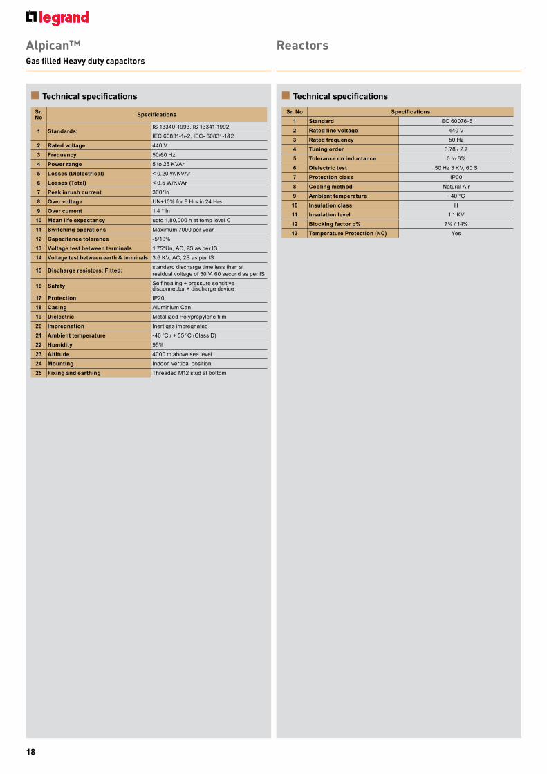
n Technical specificationsn Technical specifications
Reactors
Sr. No Specifications
1 Standard IEC 60076-6
2 Rated line voltage 440 V
3 Rated frequency 50 Hz
4 Tuning order 3.78 / 2.7
5 Tolerance on inductance 0 to 6%
6 Dielectric test 50 Hz 3 KV, 60 S
7 Protection class IP00
8 Cooling method Natural Air
9 Ambient temperature +40 °C
10 Insulation class H
11 Insulation level 1.1 KV
12 Blocking factor p% 7% / 14%
13 Temperature Protection (NC) Yes
Alpican™ Gas filled Heavy duty capacitors
Sr. No Specifications
1 Standards: IS 13340-1993, IS 13341-1992,
IEC 60831-1/-2, IEC- 60831-1&2
2 Rated voltage 440 V
3 Frequency 50/60 Hz
4 Power range 5 to 25 KVAr
5 Losses (Dielectrical) < 0.20 W/KVAr
6 Losses (Total) < 0.5 W/KVAr
7 Peak inrush current 300*In
8 Over voltage UN+10% for 8 Hrs in 24 Hrs
9 Over current 1.4 * In
10 Mean life expectancy upto 1,80,000 h at temp level C
11 Switching operations Maximum 7000 per year
12 Capacitance tolerance -5/10%
13 Voltage test between terminals 1.75*Un, AC, 2S as per IS
14 Voltage test between earth & terminals 3.6 KV, AC, 2S as per IS
15 Discharge resistors: Fitted:standard discharge time less than atresidual voltage of 50 V, 60 second as per IS
16 Safety Self healing + pressure sensitive disconnector + discharge device
17 Protection IP20
18 Casing Aluminium Can
19 Dielectric Metallized Polypropylene film
20 Impregnation Inert gas impregnated
21 Ambient temperature -40 0C / + 55 0C (Class D)
22 Humidity 95%
23 Altitude 4000 m above sea level
24 Mounting Indoor, vertical position
25 Fixing and earthing Threaded M12 stud at bottom

19
n Technical specifications
Sr.No. Specifications
1 Steps 4, 6, 8 and 12 controlled steps
2 Operation - 10 to + 50 °C
3 Storage - 20 to + 80 °C
4 Rated current 5 A
5 Operating limit 0.125 A to 5.5 A
6 Sensitive to the CT polarity No
7 Sensitive to the phase rotation polarity No
8 Frequency 50 Hz/60 Hz
9 Power factor 0.85 inductive to 0.95 capacitive
10 Same step reconnection time 1 to 600 s
11 Mode Manual & Automatic
12 Internal temperature sensor Yes
13 Volt-free contact for remote alarm Yes
14Alarm display (overvoltage, over/under compensation, overload, etc.)
Yes
n CTX3 capacitor switching units Cat.Nos 4168 74/75/76/77
Capacitor unit is connected to the terminals of the contactor to reduce the high inrush current.IEC 60947-4-1 AC 6b
Type Contactor
Maximum operating power (kvar)Max. Peak
current(A)220 - 240 V 400 - 440 V 500 - 550 V
4 168 74
CTX3 22 9 A 5 9.7 14 560
CTX3 22 12 A 6.7 12.5 18 560
CTX3 22 18 A 8.5 16.7 24 850
CTX3 22 22 A 10 18 26 1250
CTX3 40 32 A 15 25 36 1900
CTX3 40 40 A 20 33.3 48 2160
4 168 75/76CTX3 65 50 A 20 40 58 2160
CTX3 65 65 A 25 45.7 66 3040
4 168 76/77
CTX3 100 75 A 29.7 54 78 3040
CTX3 100 85 A 35 60 92 3040
CTX3 100 100 A 37 62 94 3040
Note: - When the switch is closed capacitor must be discharged before recharged. (Maximum residual voltage at terminals ≤ 50 V)
- To prevent short current, gG type fuse must be 1.5 - 2 times than rated current
Features of capacitor unit (Pre-loading resistor)- Damping resister that can limit the inrush current up to 60 x In by
closing earlier than the main contacts of the contactor- No heat loss by the serial resistor- Eliminates the switching surge- Improves the performance of the capacitor system
Operation sequenceCapacitor unit: OFFContactor: OFF
Capacitor unit
Contactor
Fig.1
Capacitor unit: OFFContactor: ON
Capacitor unit
Contactor
Fig.3
Capacitor unit: ONContactor: OFF
Capacitor unit
Contactor
Fig.2
Note - Closing sequence: Fig.1 => Fig.2 => Fig.3 Opening sequence: Fig.3 => Fig.1
CTX3
capacitor switching units
Power factor controller Eco
20
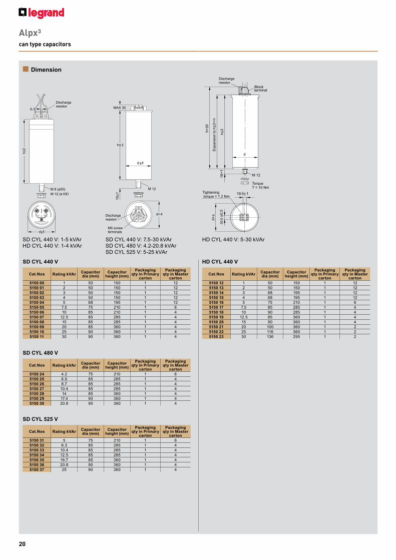
Alpx³can type capacitors
n Dimension
SD CYL 440 V: 1-5 kVArHD CYL 440 V: 1-4 kVAr
SD CYL 440 V
SD CYL 480 V
SD CYL 525 V
HD CYL 440 V
HD CYL 440 V: 5-30 kVArSD CYL 440 V: 7.5-30 kVAr SD CYL 480 V: 4.2-20.8 kVAr SD CYL 525 V: 5-25 kVAr
30.0
4
9 1
Block
3
4
Cat.Nos Rating kVAr Capacitor dia (mm)
Capacitor height (mm)
Packaging qty in Primary
carton
Packaging qty in Master
carton5150 00 1 50 150 1 125150 01 2 50 150 1 125150 02 3 50 150 1 125150 03 4 50 150 1 125150 04 5 68 195 1 125150 05 7.5 75 210 1 65150 06 10 85 210 1 45150 07 12.5 85 285 1 45150 08 15 85 285 1 45150 09 20 85 360 1 45150 10 25 90 360 1 45150 11 30 90 360 1 4
Cat.Nos Rating kVAr Capacitor dia (mm)
Capacitor height (mm)
Packaging qty in Primary
carton
Packaging qty in Master
carton5150 24 4.2 75 210 1 65150 25 6.9 85 285 1 45150 26 8.7 85 285 1 45150 27 10.4 85 285 1 45150 28 14 85 360 1 45150 29 17.4 90 360 1 45150 30 20.8 90 360 1 4
Cat.Nos Rating kVAr Capacitor dia (mm)
Capacitor height (mm)
Packaging qty in Primary
carton
Packaging qty in Master
carton5150 31 5 75 210 1 65150 32 8.3 85 285 1 45150 33 10.4 85 285 1 45150 34 12.5 85 285 1 45150 35 16.7 85 360 1 45150 36 20.8 90 360 1 45150 37 25 90 360 1 4
Cat.Nos Rating kVAr Capacitor dia (mm)
Capacitor height (mm)
Packaging qty in Primary
carton
Packaging qty in Master
carton5150 12 1 50 150 1 125150 13 2 50 150 1 125150 14 3 68 195 1 125150 15 4 68 195 1 125150 16 5 75 210 1 65150 17 7.5 85 285 1 45150 18 10 90 285 1 45150 19 12.5 85 360 1 45150 20 15 90 360 1 45150 21 20 100 360 1 25150 22 25 116 360 1 25150 23 30 136 295 1 2
08

21
Alpican™ gas filled capacitors
Alpx³box type capacitors
n Dimension n Dimension
Φ10
25
7
W2
H
D
W2
W1
H
D
SD BOX 440V: 1-50 kVAr
HD BOX 440V: 5-50 kVAr
Cat.Nos Rating kVAr
Cap Width
(W1 ±5) (mm)
Cap Width
(W2 ±5) (mm)
Cap Depth (D ±5) (mm)
Cap Height (H ±5) (mm)
Packaging qty in
Primary carton
Packaging qty in
Master carton
5150 40 1 -- 125 45 170 1 45150 41 2 -- 125 45 170 1 45150 42 3 -- 155 55 215 1 45150 43 4 -- 155 55 215 1 45150 44 5 155 185 55 230 1 15150 45 7.5 155 185 55 230 1 15150 46 8.3 155 185 55 230 1 15150 47 10 225 245 80 350 1 15150 48 12.5 225 245 80 350 1 15150 49 15 225 245 80 350 1 15150 50 20 225 250 160 300 1 15150 51 25 225 250 160 300 1 15150 52 50 225 250 320 300 1 1
Cat.Nos Rating kVAr
Cap Width
(W1 ±5) (mm)
Cap Width
(W2 ±5) (mm)
Cap Depth (D ±5) (mm)
Cap Height (H ±5) (mm)
Packaging qty in
Primary carton
Packaging qty in
Master carton
5150 53 5 225 245 80 350 1 15150 54 7.5 225 245 80 350 1 15150 55 8.33 225 245 80 375 1 15150 56 10 225 250 80 375 1 15150 57 12.5 225 250 80 375 1 15150 58 15 225 250 160 425 1 15150 59 20 225 250 160 425 1 15150 60 25 225 250 160 425 1 15150 61 50 225 250 320 425 1 1
440 V Gas filled heavy duty
Cat.NosDimensions
Diameter Height
4151 24 116 164
4151 25 116 1644151 26 116 1644151 27 116 1644151 28 116 1644151 29 116 2004151 30 136 200
4151 31 136 200

22
Reactor
Cat.Nos KVAR Rated Current L W H I1 I2 n1 n2 b e d1 d2 A B
4151 50 25 32.8A. 240 175±5mm 205 205 205 150 98±3mm 112 115±5mm 10.8 15.5 175 95
4151 51 50 65.61.A. 275 230±5mm 240 235 235 150 168±3mm 185 135±5mm 10.8 15.5 175 165
4151 52 100 131.22.A 330 180±5mm 270 285 285 150 132±3mm 155 98±5mm 10.8 15.5 175 132
Cat.Nos KVAR Rated Current L W H I1 I2 n1 n2 b e d1 d2 A B
4151 48 10 13.2A. 190 140±5mm 210 165 165 60 78±3mm 100 90±5mm 10.8 15.5 85 78
4151 49 12.5 16.4A. 190 140±5mm 210 165 165 60 78±3mm 100 90±5mm 10.8 15.5 85 78
LI1
n1 d1AI2
OPEN SLOT
WAGO TERMINAL BLOCK ELMEX CONNECTOR KUT66mm sq./800V 41ASERIES-261 2.5mm sq./500V.
d1 x d2 - 4 Nos.
H
n2BbW
e
d1
n1A
7
13n2 B
d2
WAGO TERMINAL TYPE2.5 mm sq./500 V.
OPEN SLOT
ELEVATION
d1 X d2 - 4 Nos.
R.H.SIDE VIEW
LI1
n1AI2
d1
H
n2b
d2
We
d17
13
d2
n1
A
n2 B
n Dimension

23
CTX3
capacitor switching units
Power factor controller Eco
n Dimension
96 x 96 - Models
n DimensionOverall dimensions of contactors equipped with CTX3 switching units
Cat.No 4 168 74 on CTX3 22
Cat.No 4 168 75/76 on CTX3 65
Cat.No 4 168 74 on CTX3 40
Cat.No 4 168 76/77 on CTX3 100
144 x 144 - Models
FRONT VIEW
96
96
92
92
PANEL HOLE
96
74
SIDE VIEW14
9
149
FRONT VIEW
140
140
PANEL HOLE
149
68
SIDEVIEW
14073
.5
120.445
14083
124.445
106
153.255
170
140
168.770
170

Alp
x³/1
000/
05/2
019
Technical assistance from LegrandTelephonic technical assistance for selection of products, technical information, guidance, wiring diagrams and estimation is now made available to you at each Regional Office. Contact the Technical Officer of Legrand at the following telephone numbers New Delhi : Tel.: (011) 2699 0028, 3990 2200Kolkata : Tel.: (033) 4021 3535 / 36Mumbai : Tel.: (022) 3385 6200Bangalore : Tel.: (080) 6822 0000Hyderabad : Tel.: (040) 2341 4398 / 67, 4567 1717
For other places, contact the nearest Regional / Branch / Area offices
CIN
U31
909M
H20
10P
TC20
6487
Head office
1. 61 & 62, 6th Floor, Kalpataru Square, Kondivita Road, Off Andheri-Kurla Road, Andheri (E), MUMBAI – 400 059. Tel : (022) 3041 6200 Fax : (022) 3041 6201 Website : www.legrand.co.in
Regional sales offices
2. A-25, Mohan Co-operative Industrial Estate, Mathura Road, NEW DELHI - 110 044. Tel : (011) 3990 2200, 2699 0046, (011) 2699 0028 / 29 / 30 / 31 Fax : (011) 2699 0047
3. Bhakta Towers, 2nd & 3rd Floor, Plot No. KB 22, Sector-III, Saltlake, KOLKATA – 700 098. Tel : (033) 4021 3535 / 36 Fax : (033) 4021 3537
4. C/203, Corporate Avenue, Atul Projects, Near Mirador Hotel, Chakala, Andheri Ghatkopar Link Road, Andheri – East, MUMBAI – 400 099. Tel : (022) 3385 6200 / 62301000
5. Ferozes Manor, Situated at 58 Hospital Road, Shivaji Nagar, BANGALORE – 560 001. Tel : (080) 6822 0000
6. 205-208, 2nd Floor, Block - II, White House, Kundan Bagh, Begumpet, HYDERABAD – 500 016. Tel : (040) 2341 4398 / 67, 4567 1717 Fax : (040) 4567 1730
Branch offices
7. SCO 1-2-3, Second Floor, Sector 17B, CHANDIGARH – 160 017. Tel : (0172) 305 8631 / 32 / 33 / 34 / 35 Fax : (0172) 501 9008
8. 507-510, Vth Floor, Soni Paris Point, Jai Singh Highway, Banipark, JAIPUR – 302 016. Telefax : (0141) 511 3129, 510 1179
9. 209-A, 2nd Floor, Cyber Heights, Opp. Indira Gandhi Pratishthan, Vibhuti Khand, Gomti Nagar LUCKNOW - 226 010. Tel : (522) 319 2031 / 32 / 33
10. 202 & 203, 2nd Floor, Sunrise, Forum 100, Burdwan Compound, Lalpur, RANCHI - 834 001. Tel : (651) 660 5400
11. A 101-102, Mondeal Heights, Besides Novotel Hotel, Sarkhej Gandhinagar Highway (S G Highway), AHMEDABAD – 380 015. Tel : (079) 6134 0555
12. 402, Swastik Chambers, Near Ashwamegh Marriage Hall, Behind HP Petrol Pump, Off Karve Road, Erandwane, PUNE – 411 004. Tel : (020) 6729 5601 / 602 Fax : (020) 6729 5604
13. Plot No.95, II Floor, Shreyash Heights, VIP Road, Ramdaspeth, NAGPUR – 440 010. Tel : (0712) 662 7857 / 858 Fax : (0712) 662 7859
14. 10 B, (10th Floor), Prestige Center Court Office Block Vijaya Forum Mall, #183, N.S.K. Salai, Vadapalani CHENNAI – 600 026. Tel : (044) 6612 2800 / 2362 3125 / 35 / 45 Fax : (044) 2362 3165
15. J. B. Manjooran Estate, Door No 50/1107A9, 3rd Floor, Bye Pass Junction, Edappally, COCHIN – 682 024. Tel : (0484) 280 1921 / 2921, 658 0921 Fax : (0484) 280 1921 / 2921
16. B-5, 1st Floor, Thirumalai Towers, 723, Avanashi Road, COIMBATORE – 641 018. Tel : (0422) 222 3634 / 0283 Fax : (0422) 222 3164
17. 204-205, Megapolis Square, 579, M G Road, INDORE – 452 001. Tel : (0731) 4999 891 / 892
18. MF-2, Datta’s Lords House, Jammi Chettu Street, Mogalrajapuram, VIJAYAWADA – 520 010. Tel : (0866) 661 1393, 664 6393 Fax : (0866) 669 9393
19. Plot No. 359, Saheed Nagar, 2nd Floor, BHUBANESWAR – 751 007. Tel : (0674) 254 0623
Area offices
20. Unit - 1 & 2 , Vijay Park, Main Chakrata Road, DEHRADUN - 248 001. Uttarakhand. Tel : (0135) 661 6100
21. Cabin No. 9, Second Floor, Madhok Trade Centre, Madhok Complex, Ferozpur Road, LUDHIANA – 141 001. Tel : (0161) 277 0301 / 2 / 3 / 4
22. House No. 97, Ground Floor, Rajgarh Main Road, Opp. City Heart Nursing Home, GUWAHATI – 781 007. Tel : (0361) 245 8498
23. 94, Udham Singh Sarani, Ground Floor, Ashrampara, SILIGURI – 734 001. Tel : (0353) 264 1067
24. 405, City Centre, Sosyo Circle, Udhana Magdalla Road, SURAT - 395 002. Tel : (0261) 263 3861
25. Aparna Towers, 1st Floor, 2/3, Bypass Road, MADURAI – 625 010. Telefax : (0452) 230 8414
26. 404, Eshwar Plaza, Dwaraka Nagar, Main Road, Beside Bata Show Room, VISHAKHAPATNAM – 530 016. Tel : (0891) 663 5652 Fax : (0891) 663 9363
26
19
20
17
18
13
21
8
7
16
15
6
514
12
1124
10
2223
25
9


