184
www.dell .com | support.dell.com Dell™ PowerConnect ™ 28 xx Systems User Guide
| Date post: | 07-Aug-2018 |
| Category: |
Documents |
| Upload: | erlamcastanho |
| View: | 225 times |
| Download: | 0 times |

8/21/2019 Powerconnect-2824 User's Guide en-us
http://slidepdf.com/reader/full/powerconnect-2824-users-guide-en-us 1/184
w w w . d e l l . c o m | s u p p o r t . d e l l . c o m
Dell™ PowerConnect™
28xx Systems
User Guide

8/21/2019 Powerconnect-2824 User's Guide en-us
http://slidepdf.com/reader/full/powerconnect-2824-users-guide-en-us 2/184
Notes, Notices, and Cautions NOTE: A NOTE indicates important information that helps you make better use of your computer.
NOTICE: A NOTICE indicates either potential damage to hardware or loss of data and tells you how to avoid the problem.
CAUTION: A CAUTION indicates a potential for property damage, personal injury, or death.
____________________
Information in this document is subject to change without notice.
© 2012 Dell Inc. All rights reserved.
Reproduction in any manner whatsoever without the written permission of Dell Inc. is strictly forbidden.
Trademarks used in this text: Dell , Dell OpenManage, the DELL logo, Inspiron, Dell Precision, Dimension, OptiPlex, PowerConnect , PowerApp, PowerVault , Axim, DellNet , and Latitude are trademarks of Dell Inc. Microsoft and Windows are either trademarks or registeredtrademarks of Microsoft Corporation in the United States and/or other countries.
Other trademarks and trade names may be used in this document to refer to either the entities claiming the marks and names or their products.Dell Inc. disclaims any proprietary interest in trademarks and trade names other than its own.
March 4, 2012 Rev. A04

8/21/2019 Powerconnect-2824 User's Guide en-us
http://slidepdf.com/reader/full/powerconnect-2824-users-guide-en-us 3/184
3
Contents
1 Introduction. . . . . . . . . . . . . . . . . . . . . . . . . . . . . . . . 9
System Description . . . . . . . . . . . . . . . . . . . . . . . . . . . . . . 9
PowerConnect 2808 . . . . . . . . . . . . . . . . . . . . . . . . . . . 9
PowerConnect 2816 . . . . . . . . . . . . . . . . . . . . . . . . . . . 9
PowerConnect 2824 . . . . . . . . . . . . . . . . . . . . . . . . . . . 10
PowerConnect 2848 . . . . . . . . . . . . . . . . . . . . . . . . . . . 10
Summary of PowerConnect Models . . . . . . . . . . . . . . . . . . . 11
Features . . . . . . . . . . . . . . . . . . . . . . . . . . . . . . . . . . . . 11
General Features . . . . . . . . . . . . . . . . . . . . . . . . . . . . . 11
MAC Address Supported Features . . . . . . . . . . . . . . . . . . . . 13
Layer 2 Features . . . . . . . . . . . . . . . . . . . . . . . . . . . . . 13
VLAN Supported Features . . . . . . . . . . . . . . . . . . . . . . . . 14
Spanning Tree Protocol Features . . . . . . . . . . . . . . . . . . . . . 15
Class of Service (CoS) Features . . . . . . . . . . . . . . . . . . . . . 16
Ethernet Switch Management Features. . . . . . . . . . . . . . . . . . 16
2 Hardware Description . . . . . . . . . . . . . . . . . . . . . . . . 17
Switch Port Configurations . . . . . . . . . . . . . . . . . . . . . . . . . . 17
PowerConnect 28xx Front and Back Panel Port Description . . . . . . . 17
Physical Dimensions . . . . . . . . . . . . . . . . . . . . . . . . . . . . . 21
LED Definitions . . . . . . . . . . . . . . . . . . . . . . . . . . . . . . . 21
Power LED . . . . . . . . . . . . . . . . . . . . . . . . . . . . . . . 22
Managed Mode LED. . . . . . . . . . . . . . . . . . . . . . . . . . . 22
Fan LED (2824/2848 only) . . . . . . . . . . . . . . . . . . . . . . . 22
Port LEDs . . . . . . . . . . . . . . . . . . . . . . . . . . . . . . . . 22
Managed Mode Button. . . . . . . . . . . . . . . . . . . . . . . . . . 23
Switch Ventilation Fan . . . . . . . . . . . . . . . . . . . . . . . . . . 23
Cables, Port Connections, and Pinout Information . . . . . . . . . . . . . . 24
1000BASE-T Cable Requirements. . . . . . . . . . . . . . . . . . . . 24
RJ-45 Connections for 10/100/1000BASE-T Ports . . . . . . . . . . . . 24
SFP Ports . . . . . . . . . . . . . . . . . . . . . . . . . . . . . . . . 25

8/21/2019 Powerconnect-2824 User's Guide en-us
http://slidepdf.com/reader/full/powerconnect-2824-users-guide-en-us 4/184
4
Power Connectors . . . . . . . . . . . . . . . . . . . . . . . . . . . . . . . 26
Internal Power Supply Connector . . . . . . . . . . . . . . . . . . . . 26
3 Installing the PowerConnect Device . . . . . . . . . . . . . . 27
Installation Precautions . . . . . . . . . . . . . . . . . . . . . . . . . . . . 27
Site Requirements . . . . . . . . . . . . . . . . . . . . . . . . . . . . . . . 28
Unpacking . . . . . . . . . . . . . . . . . . . . . . . . . . . . . . . . . . 28
Package Contents . . . . . . . . . . . . . . . . . . . . . . . . . . . . 28
Unpacking the Device . . . . . . . . . . . . . . . . . . . . . . . . . . 28
Mounting the Device . . . . . . . . . . . . . . . . . . . . . . . . . . . . . 29
Overview . . . . . . . . . . . . . . . . . . . . . . . . . . . . . . . . 29
Device Rack Installation . . . . . . . . . . . . . . . . . . . . . . . . . 29
Installing on a Flat Surface. . . . . . . . . . . . . . . . . . . . . . . . 30
Installing on a Wall . . . . . . . . . . . . . . . . . . . . . . . . . . . 31
Connecting the Device . . . . . . . . . . . . . . . . . . . . . . . . . . . . 33
Connecting the Device to the Network . . . . . . . . . . . . . . . . . . . . 33
Connecting the Terminal to the Device . . . . . . . . . . . . . . . . . . . . 33
Connecting a Device to a Power Supply . . . . . . . . . . . . . . . . . 34
Port Connections, Cables, and Pinout Information . . . . . . . . . . . . . . 35
RJ-45 Connections for 10/100/1000BaseT Ports . . . . . . . . . . . . . 35
Port Default Settings . . . . . . . . . . . . . . . . . . . . . . . . . . . . . 37
Auto-Negotiation . . . . . . . . . . . . . . . . . . . . . . . . . . . . 37
MDI/MDIX . . . . . . . . . . . . . . . . . . . . . . . . . . . . . . . 37
Flow Control . . . . . . . . . . . . . . . . . . . . . . . . . . . . . . . 37
Back Pressure . . . . . . . . . . . . . . . . . . . . . . . . . . . . . . 37
Switching Port Default Settings . . . . . . . . . . . . . . . . . . . . . 38
4 Starting and Configuring the Device . . . . . . . . . . . . . . 39
Management Modes. . . . . . . . . . . . . . . . . . . . . . . . . . . . . . 40
Transitioning Between Modes. . . . . . . . . . . . . . . . . . . . . . . . . 42
Booting the Device - Managed Mode . . . . . . . . . . . . . . . . . . . . . 44
Initial Configuration Through the Set-up Wizard . . . . . . . . . . . . . . . 44

8/21/2019 Powerconnect-2824 User's Guide en-us
http://slidepdf.com/reader/full/powerconnect-2824-users-guide-en-us 5/184
5
Initial Configuration Through the Web . . . . . . . . . . . . . . . . . . . . 48
Basic Configuration . . . . . . . . . . . . . . . . . . . . . . . . . . . 48
Retrieving an IP Address From a DHCP Server . . . . . . . . . . . . . 49
Startup Menu . . . . . . . . . . . . . . . . . . . . . . . . . . . . . . . . . 50
Software Download . . . . . . . . . . . . . . . . . . . . . . . . . . . 51
Erase FLASH File . . . . . . . . . . . . . . . . . . . . . . . . . . . . 51
Erasing the Device Configuration . . . . . . . . . . . . . . . . . . . . 51
Password Recovery . . . . . . . . . . . . . . . . . . . . . . . . . . . 52
Software Download Through TFTP Server . . . . . . . . . . . . . . . 52
. . . . . . . . . . . . . . . . . . . . . . . . . . . . . . . . . . . . . . . . 53
5 Using Dell OpenManage Switch Administrator . . . . . . . 54
Understanding the Interface . . . . . . . . . . . . . . . . . . . . . . . . . . 54
Using the Switch Administrator Buttons . . . . . . . . . . . . . . . . . . . 55Information Buttons . . . . . . . . . . . . . . . . . . . . . . . . . . . 55
Device Management Buttons . . . . . . . . . . . . . . . . . . . . . . 56
Starting the Application . . . . . . . . . . . . . . . . . . . . . . . . . . . . 56
Access Levels . . . . . . . . . . . . . . . . . . . . . . . . . . . . . . 56
6 Configuring System Information. . . . . . . . . . . . . . . . . 58
Defining General Device Information . . . . . . . . . . . . . . . . . . . . . 58
Viewing Device Information . . . . . . . . . . . . . . . . . . . . . . . 58
Viewing the Versions Page . . . . . . . . . . . . . . . . . . . . . . . . 60
Resetting the Device . . . . . . . . . . . . . . . . . . . . . . . . . . . 61
Entering Secure Mode . . . . . . . . . . . . . . . . . . . . . . . . . . 62
Defining Device IP Addresses . . . . . . . . . . . . . . . . . . . . . . . . 63Defining IP Interface Parameters. . . . . . . . . . . . . . . . . . . . . 63
Running Cable Diagnostics . . . . . . . . . . . . . . . . . . . . . . . . . . 64
Viewing Copper Cable Diagnostics . . . . . . . . . . . . . . . . . . . 64
Viewing Optical Transceiver Diagnostics . . . . . . . . . . . . . . . . 65
Managing Device Security . . . . . . . . . . . . . . . . . . . . . . . . . . 68
Defining the Local User Databases. . . . . . . . . . . . . . . . . . . . 68Configuring RADIUS Global Parameters . . . . . . . . . . . . . . . . 70

8/21/2019 Powerconnect-2824 User's Guide en-us
http://slidepdf.com/reader/full/powerconnect-2824-users-guide-en-us 6/184
6
Defining SNMP Parameters . . . . . . . . . . . . . . . . . . . . . . . . . . 73
Defining SNMP Global Parameters . . . . . . . . . . . . . . . . . . . 74
Defining Communities . . . . . . . . . . . . . . . . . . . . . . . . . . 75
Defining SNMP Notification Recipients . . . . . . . . . . . . . . . . . 77
Managing Files . . . . . . . . . . . . . . . . . . . . . . . . . . . . . . . . 79
Downloading Files . . . . . . . . . . . . . . . . . . . . . . . . . . . . 79
Uploading Files . . . . . . . . . . . . . . . . . . . . . . . . . . . . . 81
Restoring Default Settings . . . . . . . . . . . . . . . . . . . . . . . . 82
Defining DHCP Server Settings . . . . . . . . . . . . . . . . . . . . . . . . 83
Configuring DHCP Properties . . . . . . . . . . . . . . . . . . . . . . 83
Defining Network Pool . . . . . . . . . . . . . . . . . . . . . . . . . 85
Excluding Addresses . . . . . . . . . . . . . . . . . . . . . . . . . . . 86
Manually Allocating IP Addresses (Static Hosts) . . . . . . . . . . . . 88
Address Binding . . . . . . . . . . . . . . . . . . . . . . . . . . . . . 91
Defining Advanced Settings . . . . . . . . . . . . . . . . . . . . . . . . . 92
Configuring General Device Parameters . . . . . . . . . . . . . . . . . 92
7 Configuring Device Switching . . . . . . . . . . . . . . . . . . 93
Configuring Network Security . . . . . . . . . . . . . . . . . . . . . . . . 93
Configuring Port Based Authentication . . . . . . . . . . . . . . . . . 94
Configuring Advanced Port Based Authentication . . . . . . . . . . . . 97Authenticating Users . . . . . . . . . . . . . . . . . . . . . . . . . . . 99
Configuring Ports . . . . . . . . . . . . . . . . . . . . . . . . . . . . . . 101
Defining Port Parameters . . . . . . . . . . . . . . . . . . . . . . . 101
Aggregating Ports . . . . . . . . . . . . . . . . . . . . . . . . . . . 103
Configuring Green Ethernet . . . . . . . . . . . . . . . . . . . . . . 106
Enabling Storm Control . . . . . . . . . . . . . . . . . . . . . . . . 108
Defining Port Mirroring Sessions . . . . . . . . . . . . . . . . . . . 110
Configuring Address Tables . . . . . . . . . . . . . . . . . . . . . . . . . 112
Viewing Dynamic Addresses. . . . . . . . . . . . . . . . . . . . . . 112
Configuring the Spanning Tree Protocol . . . . . . . . . . . . . . . . . . 114
Defining STP Global Settings . . . . . . . . . . . . . . . . . . . . . 114
Defining STP Port Settings . . . . . . . . . . . . . . . . . . . . . . 117
Defining STP LAG Settings . . . . . . . . . . . . . . . . . . . . . . 120Configuring Rapid Spanning Tree . . . . . . . . . . . . . . . . . . . 122
8/21/2019 Powerconnect-2824 User's Guide en-us
http://slidepdf.com/reader/full/powerconnect-2824-users-guide-en-us 7/184
7
Configuring VLANs . . . . . . . . . . . . . . . . . . . . . . . . . . . . 124
Defining VLAN Members . . . . . . . . . . . . . . . . . . . . . . . 124
VLAN Port Membership Table . . . . . . . . . . . . . . . . . . . . 126
Defining VLAN Ports Settings . . . . . . . . . . . . . . . . . . . . . 128
Defining VLAN LAG Settings . . . . . . . . . . . . . . . . . . . . . 129
Aggregating Ports . . . . . . . . . . . . . . . . . . . . . . . . . . . . . . 131
Defining LAG Membership . . . . . . . . . . . . . . . . . . . . . . 132
Multicast Forwarding Support . . . . . . . . . . . . . . . . . . . . . . . 132
Defining Multicast Global Parameters . . . . . . . . . . . . . . . . . 133
Adding Bridge Multicast Address Members . . . . . . . . . . . . . . 134
Assigning Multicast Forward All Parameters . . . . . . . . . . . . . 136
IGMP Snooping . . . . . . . . . . . . . . . . . . . . . . . . . . . . 139
8 Viewing Statistics . . . . . . . . . . . . . . . . . . . . . . . . . . 141
Viewing RMON Statistics . . . . . . . . . . . . . . . . . . . . . . . . . . 141
Viewing RMON Statistics Group . . . . . . . . . . . . . . . . . . . 141
Viewing Charts . . . . . . . . . . . . . . . . . . . . . . . . . . . . . . . 142
Viewing the CPU Utilization . . . . . . . . . . . . . . . . . . . . . . 142
9 Configuring Quality of Service. . . . . . . . . . . . . . . . .
144Defining CoS Global Parameters . . . . . . . . . . . . . . . . . . . . . . 146
Defining CoS Settings . . . . . . . . . . . . . . . . . . . . . . . . . . . 146
Defining QoS Interface Settings. . . . . . . . . . . . . . . . . . . . . . . 147
Defining Queue Settings . . . . . . . . . . . . . . . . . . . . . . . . . . 148
Mapping CoS Values to Queues . . . . . . . . . . . . . . . . . . . . . . . 150
Mapping DSCP Values to Queues . . . . . . . . . . . . . . . . . . . . . . 151
A Managing the Device Using the CLI . . . . . . . . . . . . . 153
Accessing the Device Through the CLI . . . . . . . . . . . . . . . . . . . 153
Console Connection . . . . . . . . . . . . . . . . . . . . . . . . . . 153
Telnet Connection . . . . . . . . . . . . . . . . . . . . . . . . . . . 153

8/21/2019 Powerconnect-2824 User's Guide en-us
http://slidepdf.com/reader/full/powerconnect-2824-users-guide-en-us 8/184
8
Using the CLI . . . . . . . . . . . . . . . . . . . . . . . . . . . . . . . . 154
Command Mode Overview . . . . . . . . . . . . . . . . . . . . . . 154
User EXEC Mode . . . . . . . . . . . . . . . . . . . . . . . . . . . 154
Privileged EXEC Mode . . . . . . . . . . . . . . . . . . . . . . . . 155
Global Configuration Mode . . . . . . . . . . . . . . . . . . . . . . 155
Interface Configuration Mode . . . . . . . . . . . . . . . . . . . . . 156
CLI Commands . . . . . . . . . . . . . . . . . . . . . . . . . . . . . . . 157
Command: copy . . . . . . . . . . . . . . . . . . . . . . . . . . . . 157
Command: debug-mode . . . . . . . . . . . . . . . . . . . . . . . . 158Command: do . . . . . . . . . . . . . . . . . . . . . . . . . . . . . 158
Command: end . . . . . . . . . . . . . . . . . . . . . . . . . . . . . 159
Command: exit (configuration) . . . . . . . . . . . . . . . . . . . . 159
Command: exit (EXEC) . . . . . . . . . . . . . . . . . . . . . . . . 160
Command: help . . . . . . . . . . . . . . . . . . . . . . . . . . . . 160
Command: interface ethernet . . . . . . . . . . . . . . . . . . . . . 160
Command: interface port-channel . . . . . . . . . . . . . . . . . . . 161
Command: interface vlan . . . . . . . . . . . . . . . . . . . . . . . 161
Command: ip address . . . . . . . . . . . . . . . . . . . . . . . . . 162
Command: ping . . . . . . . . . . . . . . . . . . . . . . . . . . . . 163
Command: show tech-support command . . . . . . . . . . . . . . . . 165
Command: snmp-server community . . . . . . . . . . . . . . . . . . 166
Command: username. . . . . . . . . . . . . . . . . . . . . . . . . . 167
Glossary . . . . . . . . . . . . . . . . . . . . . . . . . . . . . . . . . . . 169
Index . . . . . . . . . . . . . . . . . . . . . . . . . . . . . . . . . . . . . 179
8/21/2019 Powerconnect-2824 User's Guide en-us
http://slidepdf.com/reader/full/powerconnect-2824-users-guide-en-us 9/184
Dell PowerConnect 28xx Systems User Guide 9
1IntroductionThis User’s Guide contains the information needed for installing, configuring and maintaining thePowerConnect 2808, PowerConnect 2816, PowerConnect 2824, and PowerConnect 2848 Web-managed Gigabit Ethernet switches.
The PowerConnect 28xx switches can be used to connect workstations and other network devices,
such as:• Servers
• Hubs
• Routers
The PowerConnect devices are primarily designated for the Small Office/Home Office (SOHO) thatrequire high performance edge connectivity. These PowerConnect devices are ideal for the small tomedium business that requires high performance network connectivity along with advanced webmanagement features. The PowerConnect management features are designed to minimizeadministrative management effort, while enhancing and improving network traffic control.
System DescriptionThis section describes the hardware configurations of the PowerConnect 28xx. The switches aremanaged by Dell’s OpenManage Switch Administrator.
PowerConnect 2808
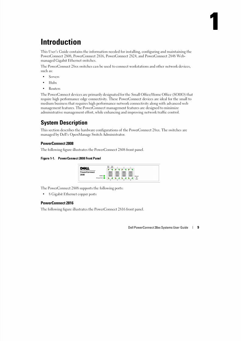
The following figure illustrates the PowerConnect 2808 front panel.
Figure 1-1. PowerConnect 2808 Front Panel
The PowerConnect 2808 supports the following ports:
• 8 Gigabit Ethernet copper ports
PowerConnect 2816
The following figure illustrates the PowerConnect 2816 front panel.
1

8/21/2019 Powerconnect-2824 User's Guide en-us
http://slidepdf.com/reader/full/powerconnect-2824-users-guide-en-us 10/184
10 Dell PowerConnect 28xx Systems User Guide
Figure 1-2. PowerConnect 2816 Front Panel
The PowerConnect 2816 supports the following ports:
• 16 Gigabit Ethernet copper ports
PowerConnect 2824
The following figure illustrates the PowerConnect 2824 front panel.
Figure 1-3. PowerConnect 2824 Front Panel
The PowerConnect 2824 supports the following ports:
• 24 Gigabit Ethernet copper ports
• 2 SFP combo ports (1000BASE-SX or 1000BASE-LX)
PowerConnect 2848
The following figure illustrates the PowerConnect 2848 front panel.
Figure 1-4. PowerConnect 2848 Front Panel
The PowerConnect 2848 supports the following ports:
• 48 Gigabit Ethernet copper ports
• 4 SFP combo ports (1000BASE-SX or 1000BASE-LX)
8/21/2019 Powerconnect-2824 User's Guide en-us
http://slidepdf.com/reader/full/powerconnect-2824-users-guide-en-us 11/184
Dell PowerConnect 28xx Systems User Guide 11
Summary of PowerConnect Models
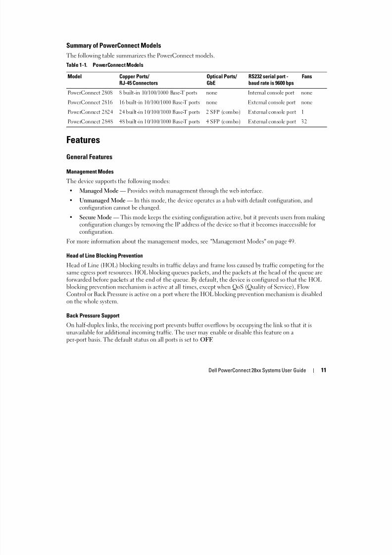
The following table summarizes the PowerConnect models.
Features
General Features
Management ModesThe device supports the following modes:
• Managed Mode — Provides switch management through the web interface.
• Unmanaged Mode — In this mode, the device operates as a hub with default configuration, andconfiguration cannot be changed.
• Secure Mode — This mode keeps the existing configuration active, but it prevents users from makingconfiguration changes by removing the IP address of the device so that it becomes inaccessible forconfiguration.
For more information about the management modes, see "Management Modes" on page 49.
Head of Line Blocking Prevention
Head of Line (HOL) blocking results in traffic delays and frame loss caused by traffic competing for thesame egress port resources. HOL blocking queues packets, and the packets at the head of the queue areforwarded before packets at the end of the queue. By default, the device is configured so that the HOL
blocking prevention mechanism is active at all times, except when QoS (Quality of Service), FlowControl or Back Pressure is active on a port where the HOL blocking prevention mechanism is disabledon the whole system.
Back Pressure Support
On half-duplex links, the receiving port prevents buffer overflows by occupying the link so that it isunavailable for additional incoming traffic. The user may enable or disable this feature on aper-port basis. The default status on all ports is set to OFF.
Table 1-1. PowerConnect Models
Model Copper Ports/ RJ-45 Connectors
Optical Ports/ GbE
RS232 serial port -baud rate is 9600 bps
Fans
PowerConnect 2808 8 built-in 10/100/1000 Base-T ports none Internal console port none
PowerConnect 2816 16 built-in 10/100/1000 Base-T ports none External console port none
PowerConnect 2824 24 built-in 10/100/1000 Base-T ports 2 SFP (combo) External console port 1
PowerConnect 2848 48 built-in 10/100/1000 Base-T ports 4 SFP (combo) External console port 32

8/21/2019 Powerconnect-2824 User's Guide en-us
http://slidepdf.com/reader/full/powerconnect-2824-users-guide-en-us 12/184
12 Dell PowerConnect 28xx Systems User Guide
Auto Negotiation
Auto negotiation allows an Ethernet switch to advertise modes of operation. The auto negotiationfunction provides the means to exchange information between two Ethernet switches that share a point-to-point link segment, and to automatically configure both Ethernet switches to take maximumadvantage of their transmission capabilities. Port advertisement allows the system administrator toconfigure the port speeds advertised.
Jumbo Frames Support
Jumbo frames are frames with an MTU (Maximum Transmission Unit) size of up to 10K bytes. The
Jumbo Frames Support feature, utilizes the network optimally by transporting the same data using lessframes.
The main benefits of this facility are reduced transmission overhead and reduced host processingoverhead. Jumbo frames are used for server-to-server transfers.
AutoMDI/MDIX Support
The switch automatically detects whether the cable connected to an RJ-45 port is crossed or straight
through.Standard wiring for end stations is Media-Dependent Interface (MDI) and the s tandard wiring for hubsand switches is known as Media-Dependent Interface with Crossover (MDIX).
Auto MDI/MDIX works on 10/100/1000BASE-T Ethernet ports. This feature is automatically enabled forthe entire system and cannot be turned off by the user.
Flow Control Support (IEEE802.3X)
On Full Duplex links (FDX), the flow control mechanism allows the receiving side to signal to thesending side that transmission must be halted temporarily, in order to prevent buffer overflows. Flowcontrol is enabled by default.
Virtual Cable Testing (VCT)
VCT technology provides the mechanism to detect and report potential cabling issues, such as cableopens and cable shorts on copper links.
Cable analysis is available on Copper Cables (10BASE-T/100BASE-T/1000BASE-T), and is only donewhen the link is down. When the system initiates a cable-testing operation, upon explicit user action, thefollowing parameters are detected:
• Cable Type and Status
• Cable Length
• Fault-Distance

8/21/2019 Powerconnect-2824 User's Guide en-us
http://slidepdf.com/reader/full/powerconnect-2824-users-guide-en-us 13/184
Dell PowerConnect 28xx Systems User Guide 13
MAC Address Supported Features
MAC Address Capacity Support
The PowerConnect 2808, 2816, 2824 switches support a total of 8K MAC addresses, and thePowerConnect 2848 supports a total of 16K MAC addresses.
Auto-Learning MAC Addresses
The switch enables MAC address auto-learning from incoming packets. The MAC addresses are stored inthe Bridging Table.
Automatic Aging for MAC Addresses
MAC addresses from which no traffic is received for a given period of time are aged out. This preventsthe Bridging Table from overflowing.
VLAN-aware MAC-based Switching in Managed and Secure Modes
In Managed or Secure mode, the switch system always performs VLAN-aware bridging. Classic bridging
(IEEE802.1D) is not performed (where frames are forwarded based only on their destination MACaddress). However, a similar functionality may be configured for untagged frames. Addresses areassociated with ports by learning them from the incoming frames source address.
802.1D Bridging in Unmanaged Mode
In Unmanaged Mode, the switch performs classic bridging. Frames are forwarded based on theirdestination MAC address only, regardless of the VLAN tag.
MAC Multicast SupportMulticast service is a limited broadcast service, which allows one-to-many and many-to-manyconnections for information distribution. Layer 2 Multicast service is where a single frame is addressed toa specific Multicast address, from where copies of the frame are transmitted to the relevant ports. IGMPSnooping is supported, including IGMP Querier which simulates the behavior of a multicast router,allowing snooping of the layer 2 multicast domain even though there is no multicast router. WhenMulticast groups are statically enabled, you can set the destination port of registered groups, as well asdefine the behavior of unregistered multicast frames.
Layer 2 Features
Green Ethernet
Green Ethernet, also known as Energy Efficient Ethernet, is an effort to make networking equipmentenvironmentally friendly, specifically by reducing power usage of Ethernet connections. The followingmethods are supported by the device:
• Energy-Detect — Auto-detection of inactivity on a port, and subsequent reducing of transmit power.

8/21/2019 Powerconnect-2824 User's Guide en-us
http://slidepdf.com/reader/full/powerconnect-2824-users-guide-en-us 14/184
14 Dell PowerConnect 28xx Systems User Guide
• Short-Reach — Reduction of power over Ethernet cables shorter than 40m.
IGMP Snooping
Internet Group Membership Protocol (IGMP) Snooping examines IGMP frame contents, when they areforwarded by the device from work stations to an upstream Multicast router. From the frame, the deviceidentifies work stations configured for Multicast sessions, and which Multicast routers are sendingMulticast frames.
Port Mirroring
The port mirroring mechanism monitors and mirrors network traffic by forwarding copies of incomingand outgoing packets from a monitored port to a monitoring port. Users can specify which target portreceives copies of all traffic passing through one or more source ports.
Storm Control
Storm Control enables limiting the amount of Multicast, Broadcast and Unknown Unicast framesaccepted and forwarded by the switch. When Layer 2 frames are forwarded, Broadcast and Multicastframes are flooded to all ports on the relevant VLAN. All nodes connected to these ports accept and
attempt to process these frames, thus placing load on both the network links and the host operatingsystem.
Dynamic VLAN Assignment (DVA)
Dynamic VLAN Assignment allows automatic assignment of users to VLANs during the RADIUS serverauthentication. When a user is authenticated by the RADIUS server, the user is automatically joined tothe VLAN configured on the RADIUS server.
VLAN Supported Features
VLAN Support
VLANs are collections of switching ports that comprise a single broadcast domain. Packets are classifiedas belonging to a VLAN based on either the VLAN tag or based on a combination of the ingress port andpackage contents. Packets sharing common attributes can be grouped in the same VLAN.
Port Based Virtual LANs (VLANs)
Port-based VLANs classify incoming packets to VLANs based on their ingress port.
Link Aggregation
The PowerConnect 28xx switches support up to eight aggregated links. Each of the eight aggregatedlinks may be defined with up to eight member ports to form a single Link Aggregated Group (LAG).
The benefits of this facility are:
• Fault tolerance protection from physical link disruption

8/21/2019 Powerconnect-2824 User's Guide en-us
http://slidepdf.com/reader/full/powerconnect-2824-users-guide-en-us 15/184
Dell PowerConnect 28xx Systems User Guide 15
• Higher bandwidth connections
• Improved bandwidth granularity
• High bandwidth server connectivity
A LAG is composed of ports with the same speed set to full-duplex operation.
DHCP Server
Dynamic Host Configuration Protocol is a method of managing network parameter assignment from asingle DHCP server. The Dynamic Host Configuration Protocol (DHCP) automates the assignment of
IP addresses, subnet masks, default gateway, and other IP parameters.
BootP and DHCP Clients
DHCP (Dynamic Host Configuration Protocol) enables additional setup parameters to be received froma network server upon system startup. DHCP service is an on-going process. DHCP is an extension toBootP.
The BootP client is operational if there is a corrupted or invalid software image. The BootP client thencontinuously attempts to find a BootP server, by sending BootP requests to all ports on the default
VLAN, until a BootP server replies. The information replied is then used to provide the switch systemwith a TFTP server IP address and a download file name. The switch can then configure these values tothe TFTP client and try to download a valid runtime image.
Spanning Tree Protocol Features
Spanning Tree Protocol (STP)
802.1d Spanning tree is a standard Layer 2 switch requirement that allows bridges to automaticallyprevent and resolve L2 forwarding loops. Switches exchange configuration messages using specificallyformatted frames and selectively enable and disable forwarding on ports.
Fast Link
STP can take up to 30-60 seconds to converge. During this time, STP detects possible loops, allowingtime for status changes to propagate and for relevant devices to respond. 30-60 seconds is considered toolong of a response time for many applications. The Fast Link option bypasses this delay, and can be used
in network topologies where forwarding loops do not occur.
IEEE 802.1w Rapid Spanning Tree
Spanning Tree can take 30-60 seconds for each host to decide whether its ports are actively forwardingtraffic. Rapid Spanning Tree (RSTP) detects uses of network topologies to enable faster convergence,without creating forwarding loops.
STP Root Guard
Root guard restricts the interface from functioning as the root port for the switch

8/21/2019 Powerconnect-2824 User's Guide en-us
http://slidepdf.com/reader/full/powerconnect-2824-users-guide-en-us 16/184
16 Dell PowerConnect 28xx Systems User Guide
Class of Service (CoS) Features
The PowerConnect 28xx system enables users to define various services for traffic classes of service. Theunderlying mechanism for supporting bandwidth management and control is based on the use ofmultiple priority queues for classifying traffic. The switches support four queues per port.
A CoS is defined by the user, whereby packets are related to the same Class of Service. After a packet hasbeen classified, it is assigned to one of the queues. The PowerConnect 28xx system can classify accordingto IPv4 information (DSCP).
Class of Service 802.1p Support
The IEEE 802.1p signaling technique is an OSI Layer 2 standard for marking and prioritizing networktraffic at the data link/MAC sub-layer. 802.1p traffic is classified and sent to the destination. Nobandwidth reservations or limits are established or enforced. 802.1p is a spin-off of the 802.1Q (VLANs)standard.
Ethernet Switch Management Features
Web-Based Management
With a Web-based management interface, the Ethernet Switches’ system can be managed from anyWeb browser. The system contains an Embedded Web Server (EWS), which serves HTML pages,through which the system can be monitored and configured.
TFTP Trivial File Transfer Protocol
The PowerConnect 28xx switches support software boot image and software download through TFTP.
Remote Monitoring
Remote Monitoring (RMON) is an extension to the Simple Network Management Protocol (SNMP),which provides network traffic statistics. RMON defines current and historical MAC-layer statistics andcontrol objects, allowing real-time information to be captured across the entire network. The switchessupport one RMON group for Ethernet statistics. The system provides a means to collect the statisticsdefined in RMON and to view the results, using the Web management interface in the system.
8/21/2019 Powerconnect-2824 User's Guide en-us
http://slidepdf.com/reader/full/powerconnect-2824-users-guide-en-us 17/184
Dell PowerConnect 28xx Systems User Guide 17
2Hardware Description
Switch Port Configurations
PowerConnect 28xx Front and Back Panel Port Description
The Dell™ PowerConnect™ 28xx switches use 10/100/1000BASE-T ports on the front panel forconnecting to a network.
The Gigabit Ethernet ports can operate at 10, 100 or 1000 Mbps. These ports support auto-negotiation, duplex mode (Half or Full duplex), and flow control. The combo 1000 Mbps opticalports can only operate at 1000 Mbps, full-duplex mode.
The following figures illustrate the front panels and back panels of the PowerConnect 28xx switches.
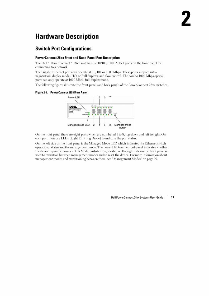
Figure 2-1. PowerConnect 2808 Front Panel
On the front panel there are eight ports which are numbered 1 to 8, top down and left to right. Oneach port there are LEDs (Light Emitting Diode) to indicate the port status.
On the left side of the front panel is the Managed Mode LED which indicates the Ethernet switchoperational status and the management mode. The Power LED on the front panel indicates whetherthe device is powered on or not. A Mode push-button, located on the right side on the front panel isused to transition between management modes and to reset the device. For more information aboutmanagement modes and transitioning between them, see "Management Modes" on page 49.
8/21/2019 Powerconnect-2824 User's Guide en-us
http://slidepdf.com/reader/full/powerconnect-2824-users-guide-en-us 18/184
18 Dell PowerConnect 28xx Systems User Guide
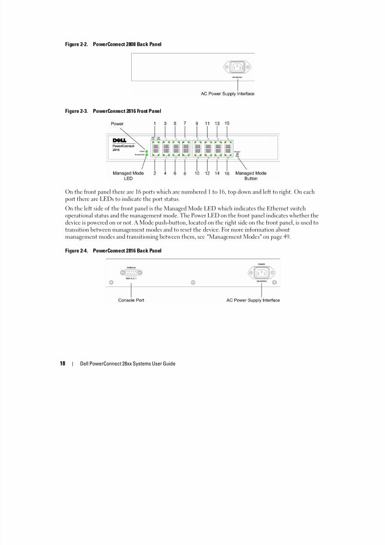
Figure 2-2. PowerConnect 2808 Back Panel
Figure 2-3. PowerConnect 2816 Front Panel
On the front panel there are 16 ports which are numbered 1 to 16, top down and left to right. On eachport there are LEDs to indicate the port status.
On the left side of the front panel is the Managed Mode LED which indicates the Ethernet switchoperational status and the management mode. The Power LED on the front panel indicates whether thedevice is powered on or not. A Mode push-button, located on the right side on the front panel, is used totransition between management modes and to reset the device. For more information aboutmanagement modes and transitioning between them, see "Management Modes" on page 49.
Figure 2-4. PowerConnect 2816 Back Panel

8/21/2019 Powerconnect-2824 User's Guide en-us
http://slidepdf.com/reader/full/powerconnect-2824-users-guide-en-us 19/184
Dell PowerConnect 28xx Systems User Guide 19
Figure 2-5. PowerConnect 2824 Front Panel
On the front panel there are 24 ports which are numbered 1 to 24, top down and left to right. On eachport there are LEDs to indicate the port status. There are two SFP (Small Form-Factor Plugable) ports,designated as ports 23 and 24, for fiber connection. The two combo ports are logical ports with twophysical connections:
• An RJ-45 connection for Twisted Pair (TP) copper cabling
• An SFP port for swappable optical transceiver, which offers high-speed 1000BASE-SX or 1000BASE-LX connection.
NOTE: Only one of the two physical connections of a combo port can be used at any one time. Port features and
port controls are determined by the physical connection used. The system automatically detects the media used on
a combo port, and utilizes the information in all the control interfaces.
NOTE: The system can switch from the RJ-45 to the SFP (or vice versa) without resetting the device. If both RJ-45
and SFP ports are present, the SFP port will be the active port, whereas the RJ-45 port will be disabled.
On the front panel is the Managed Mode LED which indicates the Ethernet switch operational statusand the management mode. The Fan LED indicates the device fan operations status, and the PowerLED on the front panel indicates whether the device is powered on or not. A Mode push-button, locatedon the right side on the front panel is used to transition between management modes and to reset thedevice. For more information about management modes and transitioning between them, see
"Management Modes" on page 49.
8/21/2019 Powerconnect-2824 User's Guide en-us
http://slidepdf.com/reader/full/powerconnect-2824-users-guide-en-us 20/184
20 Dell PowerConnect 28xx Systems User Guide
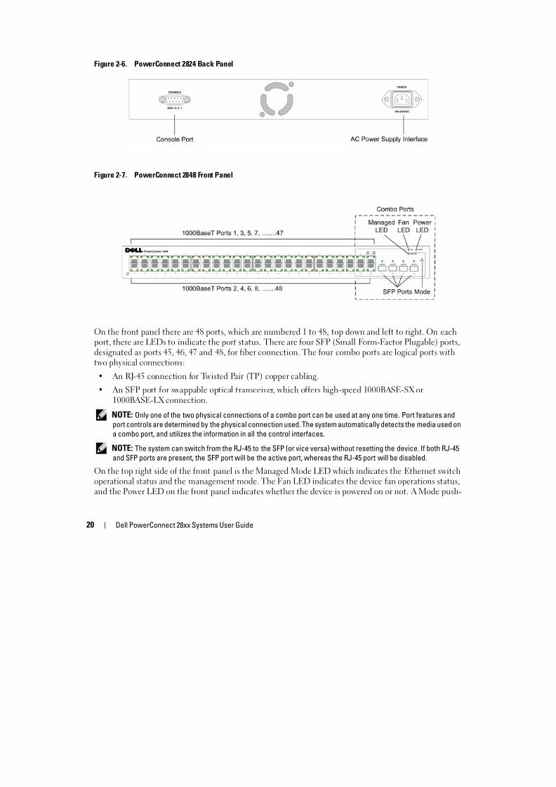
Figure 2-6. PowerConnect 2824 Back Panel
Figure 2-7. PowerConnect 2848 Front Panel
On the front panel there are 48 ports, which are numbered 1 to 48, top down and left to right. On eachport, there are LEDs to indicate the port status. There are four SFP (Small Form-Factor Plugable) ports,designated as ports 45, 46, 47 and 48, for fiber connection. The four combo ports are logical ports withtwo physical connections:
• An RJ-45 connection for Twisted Pair (TP) copper cabling.
• An SFP port for swappable optical transceiver, which offers high-speed 1000BASE-SX or1000BASE-LX connection.
NOTE: Only one of the two physical connections of a combo port can be used at any one time. Port features and
port controls are determined by the physical connection used. The system automatically detects the media used on
a combo port, and utilizes the information in all the control interfaces.
NOTE: The system can switch from the RJ-45 to the SFP (or vice versa) without resetting the device. If both RJ-45
and SFP ports are present, the SFP port will be the active port, whereas the RJ-45 port will be disabled.
On the top right side of the front panel is the Managed Mode LED which indicates the Ethernet switchoperational status and the management mode. The Fan LED indicates the device fan operations status,
and the Power LED on the front panel indicates whether the device is powered on or not. A Mode push-
8/21/2019 Powerconnect-2824 User's Guide en-us
http://slidepdf.com/reader/full/powerconnect-2824-users-guide-en-us 21/184
Dell PowerConnect 28xx Systems User Guide 21
button, located on the right side on the front panel is used to transition between management modesand to reset the device. For more information about management modes and transitioning between
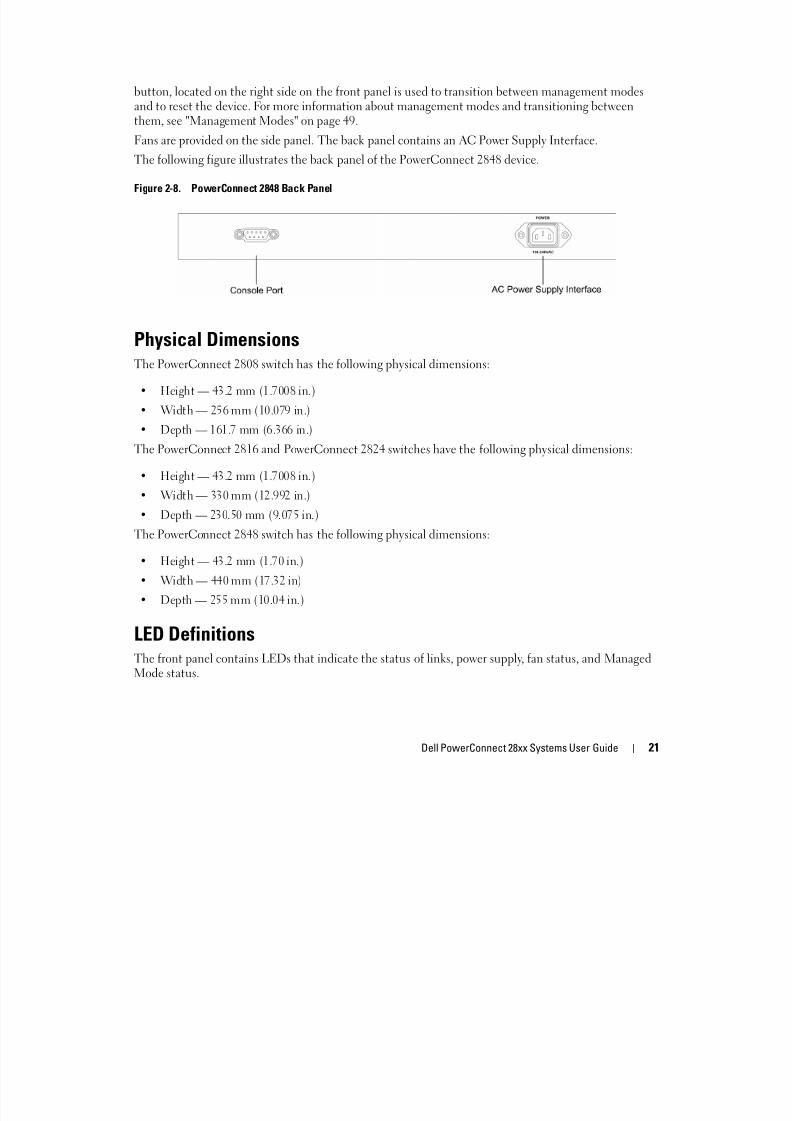
them, see "Management Modes" on page 49.Fans are provided on the side panel. The back panel contains an AC Power Supply Interface.
The following figure illustrates the back panel of the PowerConnect 2848 device.
Figure 2-8. PowerConnect 2848 Back Panel
Physical DimensionsThe PowerConnect 2808 switch has the following physical dimensions:
• Height — 43.2 mm (1.7008 in.)
• Width — 256 mm (10.079 in.)
• Depth — 161.7 mm (6.366 in.)
The PowerConnect 2816 and PowerConnect 2824 switches have the following physical dimensions:
• Height — 43.2 mm (1.7008 in.)
• Width — 330 mm (12.992 in.)
• Depth — 230.50 mm (9.075 in.)
The PowerConnect 2848 switch has the following physical dimensions:
• Height — 43.2 mm (1.70 in.)
• Width — 440 mm (17.32 in)• Depth — 255 mm (10.04 in.)
LED DefinitionsThe front panel contains LEDs that indicate the status of links, power supply, fan status, and ManagedMode status.
8/21/2019 Powerconnect-2824 User's Guide en-us
http://slidepdf.com/reader/full/powerconnect-2824-users-guide-en-us 22/184
22 Dell PowerConnect 28xx Systems User Guide
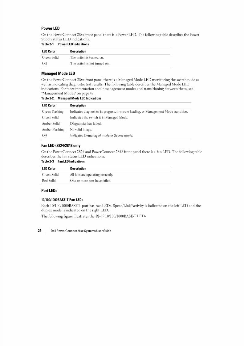
Power LED
On the PowerConnect 28xx front panel there is a Power LED. The following table describes the PowerSupply status LED indications.
Managed Mode LEDOn the PowerConnect 28xx front panel there is a Managed Mode LED monitoring the switch node aswell as indicating diagnostic test results. The following table describes the Managed Mode LEDindications. For more information about management modes and transitioning between them, see"Management Modes" on page 49.
Fan LED (2824/2848 only)
On the PowerConnect 2824 and PowerConnect 2848 front panel there is a fan LED. The following tabledescribes the fan status LED indications.
Port LEDs
10/100/1000BASE-T Port LEDs
Each 10/100/1000BASE-T port has two LEDs. Speed/Link/Activity is indicated on the left LED and theduplex mode is indicated on the right LED.
The following figure illustrates the RJ-45 10/100/1000BASE-T LEDs.
Table 2-1. Power LED Indications
LED Color Description
Green Solid The switch is turned on.
Off The switch is not turned on.
Table 2-2. Managed Mode LED Indications
LED Color Description
Green Flashing Indicates diagnostics in progress, firmware loading, or Management Mode transition.
Green Solid Indicates the switch is in Managed Mode.
Amber Solid Diagnostics has failed.
Amber Flashing No valid image.
Off Indicates Unmanaged mode or Secure mode.
Table 2-3. Fan LED Indications
LED Color Description
Green Solid All fans are operating correctly.
Red Solid One or more fans have failed.
8/21/2019 Powerconnect-2824 User's Guide en-us
http://slidepdf.com/reader/full/powerconnect-2824-users-guide-en-us 23/184
Dell PowerConnect 28xx Systems User Guide 23
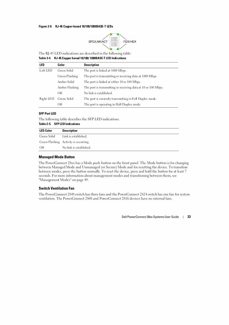
Figure 2-9. RJ-45 Copper-based 10/100/1000BASE-T LEDs
The RJ-45 LED indications are described in the following table:
SFP Port LED
The following table describes the SFP LED indications.
Managed Mode Button
The PowerConnect 28xx has a Mode push button on the front panel. The Mode button is for changing
between Managed Mode and Unmanaged (or Secure) Mode and for resetting the device. To transitionbetween modes, press the button normally. To reset the device, press and hold the button for at least 7seconds. For more information about management modes and transitioning between them, see"Management Modes" on page 49.
Switch Ventilation Fan
The PowerConnect 2848 switch has three fans and the PowerConnect 2824 switch has one fan for systemventilation. The PowerConnect 2808 and PowerConnect 2816 devices have no internal fans.
Table 2-4. RJ-45 Copper based 10/100/ 1000BASE-T LED Indications
LED Color Description
Left LED Green Solid The port is linked at 1000 Mbps.
Green Flashing The port is transmitting or receiving data at 1000 Mbps.
Amber Solid The port is linked at either 10 or 100 Mbps.
Amber Flashing The port is transmitting or receiving data at 10 or 100 Mbps.
Off No link is established.
Right LED Green Solid The port is currently transmitting in Full Duplex mode.
Off The port is operating in Half Duplex mode.
Table 2-5. SFP LED Indications
LED Color Description
Green Solid Link is established.
Green Flashing Activity is occurring.
Off No link is established.
8/21/2019 Powerconnect-2824 User's Guide en-us
http://slidepdf.com/reader/full/powerconnect-2824-users-guide-en-us 24/184
24 Dell PowerConnect 28xx Systems User Guide
Cables, Port Connections, and Pinout Information
This section explains the switch physical interfaces, and provides information about cables and portconnections. Copper cable diagnostics are supported. High-speed workstations, hubs, routers, or otherswitches are connected through standard RJ-45 connectors to the switch physical interface ports, locatedon the front panel. For each device, the supported mode is set to Half Duplex, Full Duplex, and Auto.
1000BASE-T Cable Requirements
All Category 5 UTP cables that are used for 100BASE-TX connections also operate with 1000BASE-T,provided if all four wire pairs are connected. However, it is recommended that enhanced Category 5(Category 5e)cable is used for all critical connections or any new cable installations. The Category 5especification includes test parameters that are only recommendations for Category 5, and comply withthe IEEE 802.3ab standards.
RJ-45 Connections for 10/100/1000BASE-T Ports
The 10/100/1000BASE-T ports are copper Twisted-Pair ports.
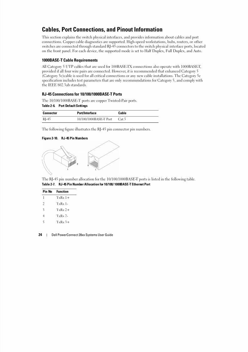
The following figure illustrates the RJ-45 pin connector pin numbers.
Figure 2-10. RJ-45 Pin Numbers
The RJ-45 pin number allocation for the 10/100/1000BASE-T ports is listed in the following table.
Table 2-6. Port Default Settings
Connector Port/Interface Cable
RJ-45 10/100/1000BASE-T Port Cat.5
Table 2-7. RJ-45 Pin Number Allocation for 10/100/ 1000BASE-T Ethernet Port
Pin No Function
1 TxRx 1+
2 TxRx 1-
3 TxRx 2+
4 TxRx 2-
5 TxRx 3+
8/21/2019 Powerconnect-2824 User's Guide en-us
http://slidepdf.com/reader/full/powerconnect-2824-users-guide-en-us 25/184
Dell PowerConnect 28xx Systems User Guide 25
SFP Ports
The PowerConnect 2824 switch supports two SFP transceivers combo ports, and the PowerConnect 2848
switch supports four SFP transceivers combo ports for various fiber-based modules (1000BASE-SX or1000BASE-LX). Only one of the two physical connections of a combo port can be used at any time. Thesystem can switch from the RJ-45 to the SFP (or vice versa) without a system reset. The systemautomatically detects the media used on a combo port, and utilizes this information in the controlinterfaces.
PowerConnect 2824 switch supports SFP diagnostics. The optical transceiver provides access to a set ofparameters that can be monitored and displayed to the system administrator.
NOTE: If both RJ-45 and SFP ports are present, the SFP port will be the active port, whereas the RJ-45 port will bedisabled and ignored.
The pin number allocation for the SFP ports is listed in the following table.
6 TxRx 3-
7 TxRx 4+
8 TxRx 4-
Table 2-8. SFP Pin Connections
Pin No Use
1 Transmitter ground (common with receiver ground)
2 Transmitter fault3 Transmitter disable; laser output disabled on high or open.
4 Module definition 2; data line for serial ID.
5 Module definition 1; clock line for serial ID.
6 Module definition 0; grounded within the module.
7 Rate select; no connection required.
8 Loss of signal indication; logic 0 indicates normal operation.9 Receiver ground (common with transmitter ground)
10 Receiver ground (common with transmitter ground)
11 Receiver ground (common with transmitter ground)
12 Receiver inverted data out; AC coupled.
13 Receiver non-inverted data out; AC coupled.
14 Receiver ground (common with transmitter ground)
Table 2-7. RJ-45 Pin Number Allocation for 10/100/ 1000BASE-T Ethernet Port
Pin No Function

8/21/2019 Powerconnect-2824 User's Guide en-us
http://slidepdf.com/reader/full/powerconnect-2824-users-guide-en-us 26/184
26 Dell PowerConnect 28xx Systems User Guide
Power ConnectorsThe PowerConnect 28xx is powered by using the AC internal power supply.
Internal Power Supply Connector
The PowerConnect 28xx supports a single internal power supply to provide power for switching
operations. The internal power supply supports input voltages between 100 and 240 VAC. The AC powerconnector is located on the back panel of the switch.
15 Receiver power supply
16 Transmitter power supply
17 Transmitter ground (common with receiver ground)
18 Transmitter non-inverted data in
19 Transmitter inverted data in
20 Transmitter ground (common with receiver ground)
Table 2-8. SFP Pin Connections
Pin No Use
3
8/21/2019 Powerconnect-2824 User's Guide en-us
http://slidepdf.com/reader/full/powerconnect-2824-users-guide-en-us 27/184
Dell PowerConnect 28xx Systems User Guide 27
3Installing the PowerConnect DeviceThis section contains information about device unpacking, location, installation, and cableconnections.
Installation Precautions CAUTION Before performing any of the following procedures, read and follow the safety instructions located
in the System Information Guide included in the Dell Documentation.
CAUTION Observe the following points before performing the procedures in this section:
• Ensure that the rack or cabinet housing the device is adequately secured to prevent it frombecoming unstable and/or falling over.
• Ensure that the power source circuits are properly grounded.
• Observe and follow the service markings. Do not service any device except as explained in thesystem documentation. Opening or removing covers marked with a triangular symbol with alighting bolt may cause electrical shock. These components are to be serviced by trained servicetechnicians only.
• Ensure that the power cable, extension cable, and/or plug is not damaged.
• Ensure that the device is not exposed to water.
• Ensure that the device is not exposed to radiators and/or heat sources.
• Ensure that the cooling vents are not blocked.
• Do not push foreign objects into the device, as it may cause a fire or electric shock.
• Use the device only with approved equipment.
• Allow the device to cool before removing covers or touching internal equipment.
• Ensure that the device does not overload the power circuits, wiring, and over-current protection.To determine the possibility of overloading the supply circuits, add together the ampere ratings of
all switches installed on the same circuit as the device. Compare this total with the rating limit forthe circuit.
• Do not install the device in an environment where the operating ambient temperature mightexceed 45ºC (113ºF).
• Ensure that the airflow around the front, sides, and back of the device is not restricted.
8/21/2019 Powerconnect-2824 User's Guide en-us
http://slidepdf.com/reader/full/powerconnect-2824-users-guide-en-us 28/184
28 Dell PowerConnect 28xx Systems User Guide
Site Requirements
The PowerConnect 28xx can be mounted in a standard equipment rack, placed on a tabletop, ormounted on the wall.
Before installing the device, verify that the site selected for the device meets the following siterequirements:
• Power — The device is installed within 1.5 m (5 feet) of a grounded, easily accessible outlet 220/110VAC, 50/60 Hz. If the device has two power supplies, the site should have two power outlets withdifferent power feeders.
• General — Ensure that the power supply is correctly installed.• Clearance — There is adequate frontal clearance for operator access. Allow clearance for cabling,
power connections, and ventilation.
• Cabling — Cabling is routed to avoid sources of electrical noise such as radio transmitters, broadcastamplifiers, power lines, and fluorescent lighting fixtures.
• Ambient Requirements — The ambient device operating temperature range is 0 to 45 °C (32 to113 °F) at a relative humidity of up to 95%, non-condensing. Verify that water or moisture cannot enter
the device case.
Unpacking
Package Contents
While unpacking the device, ensure that the following items are included:
• The device
• AC power cable
• Self-adhesive rubber pads (for on-shelf installation)
• Rack-mount kit for installation
• Documentation CD
• Product Information Guide
Unpacking the Device
To unpack the PowerConnect device:
NOTE: Before unpacking the device, inspect the packaging and report any evidence of damage.
1 Place the box on a clean flat surface.
2 Open the box or remove the box top.
3 Carefully remove the device from the package and place it on a secure, stable and clean surface.
4 Remove all packing material.
8/21/2019 Powerconnect-2824 User's Guide en-us
http://slidepdf.com/reader/full/powerconnect-2824-users-guide-en-us 29/184
Dell PowerConnect 28xx Systems User Guide 29
5 Inspect the product for damage. Report any damage immediately.
Mounting the Device
Overview
There are three device mounting options:
• Installing in a Rack
• Installing on a Flat Surface
• Installing on a Wall
Device Rack Installation
CAUTION Read the safety information in the Product Information Guide as well as the safety information for otherdevices that connect to or support the switch.
CAUTION Disconnect all cables from the device before mounting the device in a rack or cabinet.
CAUTION When mounting multiple devices into a rack, mount the devices from the bottom up.Install the device in a rack as follows:
1 Place the supplied rack-mounting bracket on one side of the device ensuring the mounting holes onthe device line up to the mounting holes on the rack mounting bracket. The following figure illustrateswhere to mount the brackets.
8/21/2019 Powerconnect-2824 User's Guide en-us
http://slidepdf.com/reader/full/powerconnect-2824-users-guide-en-us 30/184
30 Dell PowerConnect 28xx Systems User Guide
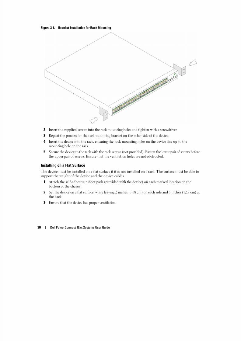
Figure 3-1. Bracket Installation for Rack Mounting
2 Insert the supplied screws into the rack mounting holes and tighten with a screwdriver.
3 Repeat the process for the rack-mounting bracket on the other side of the device.
4 Insert the device into the rack, ensuring the rack-mounting holes on the device line up to themounting hole on the rack.
5 Secure the device to the rack with the rack screws (not provided). Fasten the lower pair of screws beforethe upper pair of screws. Ensure that the ventilation holes are not obstructed.
Installing on a Flat Surface
The device must be installed on a flat surface if it is not installed on a rack. The surface must be able to
support the weight of the device and the device cables.1 Attach the self-adhesive rubber pads (provided with the device) on each marked location on the
bottom of the chassis.
2 Set the device on a flat surface, while leaving 2 inches (5.08 cm) on each side and 5 inches (12.7 cm) atthe back.
3 Ensure that the device has proper ventilation.
8/21/2019 Powerconnect-2824 User's Guide en-us
http://slidepdf.com/reader/full/powerconnect-2824-users-guide-en-us 31/184
Dell PowerConnect 28xx Systems User Guide 31
Installing on a Wall
To mount the device on a wall:
1 Ensure that the mounting location meets the following requirements:
• The surface of the wall must be capable of supporting the device.
• Allow at least 2 inches (5.1 cm) space on the sides for proper ventilation and 5 inches (12.7 cm) atthe back for power cable clearance.
• The location must not be exposed to direct sunlight.
• The location must be at least 2 feet (61 cm) away from any heating vents, and no area-heating
vent should point towards the device.• The location must be ventilated to prevent heat buildup.
• Do not locate the device near any data or electrical cabling.
• The power cable must be able to reach an outlet.
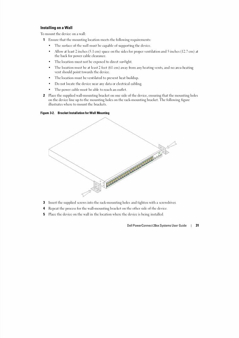
2 Place the supplied wall-mounting bracket on one side of the device, ensuring that the mounting holeson the device line up to the mounting holes on the rack-mounting bracket. The following figureillustrates where to mount the brackets.
Figure 3-2. Bracket Installation for Wall Mounting
3 Insert the supplied screws into the rack-mounting holes and tighten with a screwdriver.
4 Repeat the process for the wall-mounting bracket on the other side of the device.
5 Place the device on the wall in the location where the device is being installed.
8/21/2019 Powerconnect-2824 User's Guide en-us
http://slidepdf.com/reader/full/powerconnect-2824-users-guide-en-us 32/184
32 Dell PowerConnect 28xx Systems User Guide
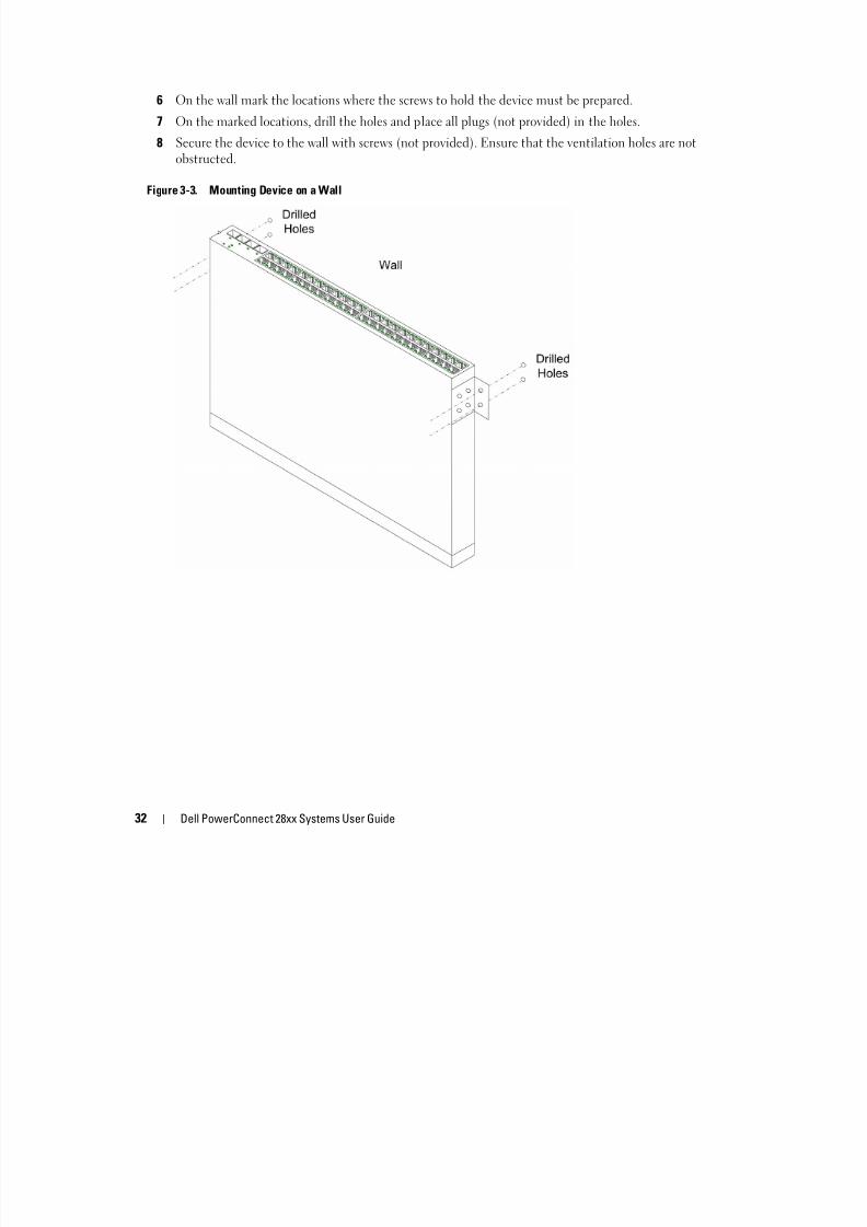
6 On the wall mark the locations where the screws to hold the device must be prepared.
7 On the marked locations, drill the holes and place all plugs (not provided) in the holes.
8 Secure the device to the wall with screws (not provided). Ensure that the ventilation holes are notobstructed.
Figure 3-3. Mounting Device on a Wall
8/21/2019 Powerconnect-2824 User's Guide en-us
http://slidepdf.com/reader/full/powerconnect-2824-users-guide-en-us 33/184
Dell PowerConnect 28xx Systems User Guide 33
Connecting the Device
To configure the device, the device must be connected to a terminal.
Connecting the Device to the NetworkTo connect to an uplink port, use Category 5 Unshielded Twisted-Pair (UTP) cables with RJ-45connectors at both ends. The RJ-45 ports on the Ethernet device support automatic Media-DependentInterface/Media-Dependent Interface with internal crossover wiring (MDI/MDIX) operation under
Auto-Negotiation mode. Standard straight-through twisted-pair cables can be used to connect to any
other Ethernet network (systems, servers, switches or routers) that supports auto-negotiation. NOTE: Do not plug a phone jack connector into an RJ-45 port. This will damage the Ethernet device. Use only
twisted-pair cables with RJ-45 connectors that conform to FCC standards.
NOTE: If auto negotiation is turned off on the ports, a straight through cable must be used.
To connect the device to the network:
1 Attach one end of a Twisted-Pair cable to the device’s RJ-45 connector and the other end to a switch orserver.
2 Make sure each twisted pair cable does not exceed 328 feet (100 meters) in length.
As each connection is made, the link LED corresponding to each port on the device is illuminated (greenor amber) indicating that the connection is valid.
Connecting the Terminal to the DeviceThe device provides an external console port in models 28016/24/48. The console port enables a
connection to a terminal desktop system running terminal emulation software for monitoring andconfiguring the device.
The Console port connector is a male DB-9 connector, implemented as a data terminal equipment(DTE) connector.
To use the Console port, the following is required:
• VT100 compatible terminal or a desktop or portable system with a serial port and running VT100terminal emulation software.
• An RS-232 crossover cable with a female DB-9 connector for the Console port and the appropriateconnector for the terminal.
To connect a terminal to the device Console port, perform the following:
1 Connect the supplied RS-232 crossover cable to the terminal running VT100 terminal emulationsoftware.
2 Ensure that the terminal emulation software is set as follows:
a Select the appropriate serial port (serial port 1 or serial port 2) to connect to the console.
8/21/2019 Powerconnect-2824 User's Guide en-us
http://slidepdf.com/reader/full/powerconnect-2824-users-guide-en-us 34/184
34 Dell PowerConnect 28xx Systems User Guide
b Set the data rate to 9600 baud.
c Set the data format to 8 data bits, 1 stop bit, and no parity.
d Set flow control to none.
e Under Properties, select VT100 for Emulation mode.
f Select Terminal keys for Function, Arrow, and Ctrl keys. Ensure that the setting is for Terminalkeys (not Windows keys).
NOTE: When using HyperTerminal with Microsoft® Windows 2000, Windows XP, or Windows Vista, ensure that
you have the latest service packs installed. With Windows 2000 Service Pack 2, the arrow keys function properly in
HyperTerminal’s VT100 emulation. Go to www.microsoft.com for information on Windows 2000, Windows XP, and
Windows Vista service packs.
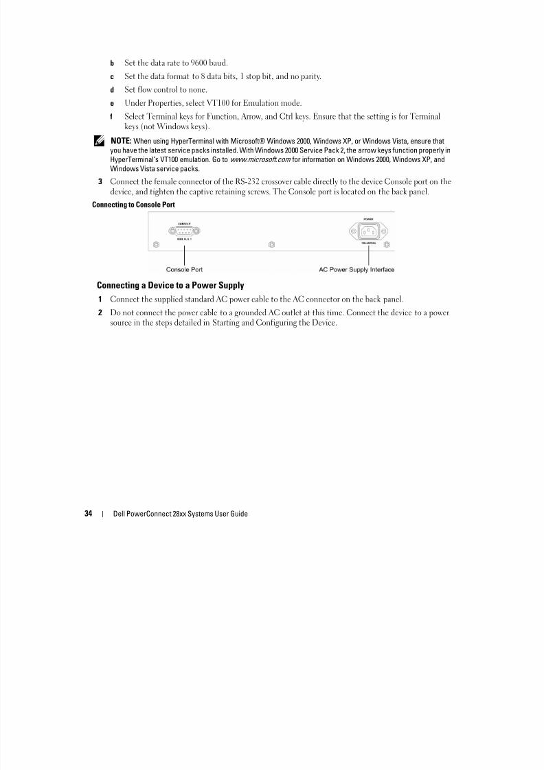
3 Connect the female connector of the RS-232 crossover cable directly to the device Console port on thedevice, and tighten the captive retaining screws. The Console port is located on the back panel.
Connecting to Console Port
Connecting a Device to a Power Supply
1 Connect the supplied standard AC power cable to the AC connector on the back panel.
2 Do not connect the power cable to a grounded AC outlet at this time. Connect the device to a power
source in the steps detailed in Starting and Configuring the Device.

8/21/2019 Powerconnect-2824 User's Guide en-us
http://slidepdf.com/reader/full/powerconnect-2824-users-guide-en-us 35/184
Dell PowerConnect 28xx Systems User Guide 35
Figure 3-4. Connecting to Power Supply
3 After connecting the device to a power source, confirm that the device is connected and operatingcorrectly by examining the LEDs on the front panel.
Port Connections, Cables, and Pinout InformationThis section explains the device’s physical interfaces, and provides information about port connections.Connector types, ports and cables are summarized in Ports, Connectors, and Cables. Copper Cable andOptical Transceiver Diagnostics are supported.
RJ-45 Connections for 10/100/1000BaseT Ports
The 10/100/1000BaseT ports are copper twisted-pair ports.
To establish a link for the twisted-pair ports, Tx pair on one cable end must be connected to the Rx pairon the other cable end, and vice versa. If the cabling is done such that Tx on one end is wired to Tx onthe other end, and Rx is wired to Rx, a link is not established.
When selecting cables to connect the device ports to their networking peers, straight through cables mustbe used to connect the device to a station, and crossover cables must be used to connect one transmissiondevice (switch or hub) to another. Both the straight through and crossover cables are category 5.
After a port is connected, its LINK indication LED is lit.

8/21/2019 Powerconnect-2824 User's Guide en-us
http://slidepdf.com/reader/full/powerconnect-2824-users-guide-en-us 36/184
36 Dell PowerConnect 28xx Systems User Guide
Table 3-1. Ports, Connectors and Cables
The RJ-45pin number allocation for the 10/100/1000BaseT ports is listed in the table following.
Table 3-2. RJ-45 Pin Number Allocation for 10/100/1000BaseT Ethernet Port
Connector Port/Interface Cable
RJ-45 10/100/1000BaseT Port Cat.5
Pin No Function
1 TxRx 1+
2 TxRx 1-
3 TxRx 2+
4 TxRx 2-
5 TxRx 3+
6 TxRx 3-
7 TxRx 4+
8 TxRx 4-

8/21/2019 Powerconnect-2824 User's Guide en-us
http://slidepdf.com/reader/full/powerconnect-2824-users-guide-en-us 37/184
Dell PowerConnect 28xx Systems User Guide 37
Port Default Settings
The general information for configuring the device ports includes the short description of the auto-negotiation mechanism and the default settings for switching ports.
Auto-Negotiation
Auto-negotiation enables automatic detection of speed, duplex mode and flow control on switching10/100/1000BaseT ports. Auto-negotiation is enabled per port by default.
Auto-negotiation is a mechanism established between two link partners to enable a port to advertise itstransmission rate, duplex mode and flow control (the flow control by default is enabled) abilities to itspartner. The ports then both operate at the highest common denominator between them.
If connecting a NIC that does not support auto-negotiation or is not set to auto-negotiation, both thedevice switching port and the NIC must be manually set to the same speed and duplex mode.
If the station on the other side of the link attempts to auto-negotiate with a device 10/100/1000BaseTport that is configured to full duplex, the auto-negotiation results in the station attempting to operate inhalf duplex.
MDI/MDIX
The device supports auto-detection of straight through and crossed cables on all switching10/100/1000BaseT ports. The feature is part of the Auto-negotiation and is enabled when Auto-negotiationis enabled.
When the MDI/MDIX (Media Dependent Interface with Crossover) is enabled, the automaticcorrection of errors in cable selection is possible, making the distinction between a straight through cable
and a crossover cable irrelevant. (The standard wiring for end stations is known as MDI (MediaDependent Interface), and the standard wiring for hubs and switches is known as MDIX.)
Flow Control
The device supports 802.3x Flow Control for ports configured with the Full Duplex mode. By default,this feature is enabled. It can be enabled per port. The flow control mechanism allows the receiving sideto signal to the transmitting side that transmission must temporarily be halted to prevent buffer
overflow.
Back Pressure
The device supports back pressure for ports configured to half duplex mode. By default, this feature isdisabled. It can be enabled per port. The back pressure mechanism prevents the transmitting side fromtransmitting additional traffic temporarily. The receiving side may occupy a link so it becomesunavailable for additional traffic.

8/21/2019 Powerconnect-2824 User's Guide en-us
http://slidepdf.com/reader/full/powerconnect-2824-users-guide-en-us 38/184
38 Dell PowerConnect 28xx Systems User Guide
Switching Port Default Settings
The following table gives the port default settings.
Table 3-3. Port Default Settings
Function Default Setting
Port speed and mode 10/100/1000BaseT copper: auto-negotiation full duplex
Port forwarding state Enabled
Port tagging No tagging
Flow Control On
Back Pressure Off (disabled on ingress)
MDIX (not user-configurable) On (relevant to coppers ports only)
4

8/21/2019 Powerconnect-2824 User's Guide en-us
http://slidepdf.com/reader/full/powerconnect-2824-users-guide-en-us 39/184
Dell PowerConnect 28xx Systems User Guide 39
443+
Starting and Configuring the Device After completing all external connections, the device must be configured. This section describesvarious methods of configuring the device.
NOTE: The PowerConnect 2808 has an internal serial port.
NOTE: Before proceeding, read the release notes for this product. The release notes can be downloaded
from http: support dell com. It is recommended that you obtain the most recent revision of the user
documentation from the Dell support website athttp: support dell com
.
NOTE: If the device is to be used as an unmanaged switch, there is no need for a terminal connection. A terminal connection is only required if the device is to be used in Managed mode. See "Management Modes"
on page 40 for a description of these modes.
Figure 4-1 provides an overview of the device initialization process.
This section covers the following topics:
• "Management Modes" on page 40
• "Transitioning Between Modes" on page 42
• "Booting the Device - Managed Mode" on page 44
• "Initial Configuration Through the Set-up Wizard" on page 44
• "Initial Configuration Through the Web" on page 48
• "Startup Menu" on page 50

8/21/2019 Powerconnect-2824 User's Guide en-us
http://slidepdf.com/reader/full/powerconnect-2824-users-guide-en-us 40/184
40 Dell PowerConnect 28xx Systems User Guide
Figure 4-1. Installation and Configuration Flow
Management ModesThe device can be run in Managed or Unmanaged mode. By default, the device is in Unmanaged mode.
These modes are described below:• Managed Mode — In this mode:
– Switch can be managed through the web interface.
– Managed Mode LED is ON.
– Device uses the saved running configuration (if it exists) or the default configuration.
Connect Device andConsole
Power On
Suspend
Bootup
Yes
Press Esc
Startup Menu (SpecialFunctions)
Reboot
No
Loading Program fromflash to RAM
Enter Wizard
Yes
No
Initial Configuration: IPAddress, Subnet mask,Users Basic Security
Configuration
Wizard Configuration
Process
Advanced Configuration: IP
Address from DHCP
StandardDevice
Installation
AdvancedDevice
Installation
Hardware
Setup

8/21/2019 Powerconnect-2824 User's Guide en-us
http://slidepdf.com/reader/full/powerconnect-2824-users-guide-en-us 41/184
Dell PowerConnect 28xx Systems User Guide 41
– The current running configuration is automatically saved to local storage. If the system is switchedto unmanaged mode via the Managed Mode button, the system does not load the saved
configuration, but it is still maintained in the device’s local storage.– From Managed mode, you can move to Unmanaged mode by pressing the Mode button on the
device, or you can move to Secure mode using the web interface (see "Entering Secure Mode" onpage 62).
The factory default values, used when the device is in Managed mode, include:
– IP Address — 192.168.2.1
– Netmask — 255.255.255.0
– Username — admin
– Permission — R/W privilege
– DHCP Client — Off
– Flow Control — On
– STP — Off
• Unmanaged Mode — In this mode:
– The device does not have an IP address.
– STP is disabled.
– All ports belong to a single VLAN.
– There is no web management interface.
– The CLI works in Debug mode only.
– Default configuration is used.
– Managed Mode LED is OFF.
– Return to Managed mode by pressing the Mode button on the device for up to 7 seconds.
• Secure Mode — In this mode:
– This mode can be entered only from the Web management.
– The device retains the existing configuration active, but it prevents users from makingconfiguration changes by removing the IP address of the device so that it becomes inaccessible for
configuration.
– No web management interface is available, and the CLI works in Debug mode only.
– Managed Mode LED is OFF.
– Return to Managed mode by pressing the Mode button on the device for up to 7 seconds.
All modes are maintained throughout power cycles. The Managed Mode LED shows the current mode.

8/21/2019 Powerconnect-2824 User's Guide en-us
http://slidepdf.com/reader/full/powerconnect-2824-users-guide-en-us 42/184
42 Dell PowerConnect 28xx Systems User Guide
Transitioning Between ModesFigure 4-5 shows the transition between Managed, Secure and Unmanaged operating modes:
Figure 4-2. Transitioning Between Management Modes
Note the following points:
• The Managed Mode LED designates whether the management interface is active on the switch. The
LED is ON only in the Managed mode, and OFF in Secure and Unmanaged modes.
Device is in Management
Mode
Device reboots in
Secure mode with
the current
configuration but
no IP address
(Managed Mode
LED is OFF)
User presses
Managed Mode
button for less
than 7 seconds. In
Device reboots in
Managed mode.
Note: See detailsbelow regarding
restore default
configuration page
on PC2808
User presses
Managed Mode
button for less
than 7 seconds.
User selects Web
option to go to
Secure mode).
Removemanagement IP
from switch (it is
no longer
manageable).
Device reboots in
Unmanaged mode
and switch
operates as a true
unmanaged switch
(Managed Mode
LED is OFF).
User presses
Managed Mode
button. Device
reboots in
Managed mode.
Note: See details
below regarding
restore default
configuration page
on PC2808
8/21/2019 Powerconnect-2824 User's Guide en-us
http://slidepdf.com/reader/full/powerconnect-2824-users-guide-en-us 43/184
Dell PowerConnect 28xx Systems User Guide 43
• Power cycle returns the switch to the same state that existed prior to the power cycle, andconfiguration is preserved.
• The user can only save or restore configurations while in Managed mode. There is no managementinterface available in Secure or Unmanaged mode to enable the user to modify, save or restoreconfigurations.
• Since the device can only enter Secure mode via an option from the web interface, it can onlytransition into Secure mode from Managed mode. After the system is in Secure mode, it retains its lastrunning configuration, but does not have a management IP address (cannot be managed from the webinterface).
Transition to managed mode on PC2816/24/48 devices• A transition from Unmanaged or Secure mode to Managed mode via the use of the Managed Mode
button results in the switch automatically rebooting and returning to Managed mode while runningthe saved configuration (if no configuration exists, then the default configuration is used).
Transition to managed mode on PC2808 devices
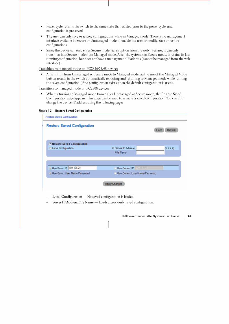
• When returning to Managed mode from either Unmanaged or Secure mode, the Restore SavedConfiguration page appears. This page can be used to retrieve a saved configuration. You can also
change the device IP address using the following page:
Figure 4-3. Restore Saved Configuration
– Local Configuration — No saved configuration is loaded.
– Server IP Address/File Name — Loads a previously saved configuration.

8/21/2019 Powerconnect-2824 User's Guide en-us
http://slidepdf.com/reader/full/powerconnect-2824-users-guide-en-us 44/184
44 Dell PowerConnect 28xx Systems User Guide
– Use Saved IP/User Name/Password — When restoring local configuration, this option uses the IPaddress, user name and password that were automatically saved when you exited Managed mode.
When restoring a saved configuration, this option uses the IP address, user name and passwordinside the saved configuration.
– Use Current IP/User Name/Password — When restoring local configuration, this option uses thesystem default IP address, user name and password.
– Apply Changes — The selected configuration is restored and the device reboots.
Booting the Device - Managed ModeThe procedure described in this section refers to the device when set to Managed mode. See Figure 4-2 for a description of how to enter the Managed mode
In managed mode, the boot procedure can be monitored on the connected terminal as follows:
1 Ensure that the device console port is connected to a VT100 terminal device or VT100 terminalemulator via the RS-232 crossover cable.
2 Locate an AC power receptacle.
3 Deactivate the AC power receptacle.4 Connect the device
to the AC receptacle.
5 Activate the AC power receptacle.
When the power is turned on with the local terminal already connected, the device goes throughPower On Self Test (POST). POST runs every time the device is initialized and checks hardwarecomponents to determine if the device is fully operational before completely booting. If a criticalproblem is detected, the program flow stops. If POST passes successfully, a valid executable image is
loaded into RAM. POST messages are displayed on the terminal and indicate test success or failure.6 The boot process begins running in less than 45 seconds when in Unmanaged mode (and
approximately 90 seconds when in other modes).
Initial Configuration Through the Set-up WizardTo configure the device, it must be in Management mode.
NOTE: The switch is factory-set in Unmanaged Mode. To set the switch to Managed mode, press the Mode buttonfor up to 7 seconds.
In Management mode, you can configure the device in the following ways:
• Through the web management application (described in "Initial Configuration Through the Web" onpage 48).
• Through the Set-up wizard, as described below.
NOTE: The initial simple configuration uses the following assumptions:
• The PowerConnect device was never configured before, and is in the same state as when you received it.

8/21/2019 Powerconnect-2824 User's Guide en-us
http://slidepdf.com/reader/full/powerconnect-2824-users-guide-en-us 45/184
Dell PowerConnect 28xx Systems User Guide 45
• The PowerConnect device booted successfully.
• The console connection is established and the console prompt is displayed on the screen of a VT100 terminal
device. (Press the <Enter> key several times to verify that the prompt displays correctly.)
The system prompts you to use the Set-up wizard when the device boots up for the first time or if theconfiguration file is empty. The Setup Wizard provides guidance through the initial device configuration,and gets the device up and running as quickly as possible.
NOTE: Obtain the following information from your network administrator before configuring the device:
• SNMP Community String and SNMP Management System IP address (optional).
• Username and password.
• The IP address to be assigned to the VLAN 1 interface through which the device is to be managed (by default,every external and internal port is a member of the VLAN 1).
• The IP subnet mask for the network.
• The default gateway (next hop router) IP address for configuring the default route.
You can skip using the setup wizard and configure the device manually through the device CLI mode (see"Managing the Device Using the CLI" on page 153.)
The Setup Wizard configures the following fields.
• SNMP Community String and SNMP Management System IP address (optional)
• Username and Password
• Device IP address
• IP subnet mask
• Default Gateway IP address
The Setup Wizard displays the following information:
Welcome to Dell Easy Setup Wizard.
The Setup Wizard guides you through the initial switch configuration,and gets you up and running as quickly as possible. You can skip thesetup wizard, and enter CLI mode to manually configure the switch.The system will prompt you with a default answer; by pressing enter,you accept the default. You must respond to the next question to runthe setup wizard within 60 seconds, otherwise the system will
continue with normal operation using the default systemconfiguration.
Would you like to enter the setup wizard (you must answer thisquestion within 60 seconds)? (Y/N)[Y] Y
NOTE: If you select not to use the Setup Wizard, you can access the Web interface by using the default IP
address/mask (192.168.2.1/255.255.255.0).
NOTE: You can exit the Setup Wizard at any time by entering [Ctrl+Z].
Wi d S 1

8/21/2019 Powerconnect-2824 User's Guide en-us
http://slidepdf.com/reader/full/powerconnect-2824-users-guide-en-us 46/184
46 Dell PowerConnect 28xx Systems User Guide
Wizard Step 1
The following information displays:
The system is not setup for SNMP management by default.
To manage the switch using SNMP (required for Dell Network Manager)you can:
*Setup the initial SNMP Version 2 account now
*Return later and setup additional SNMP v1/v2 accounts
For more information on setting up SNMP accounts, please see the userdocumentation.
Would you like to setup the SNMP management interface now? (Y/N)[Y] Y
Enter [N] to skip to Step 2.
Enter [Y] to continue the Set-up wizard. The following information displays:
To setup the SNMP management account you must specify the managementsystem IP address and the "community string" or password that the
particular management system uses to access the switch. The wizardautomatically assigns the highest access level [Privilege Level 15]to this account.
You can use Dell Network Manager or CLI to change this setting, andto add additional management systems. For more information on addingmanagement systems, see the user documentation.
To add a management station:
Please enter the SNMP community string to be used:[Dell_Network_Manager]
Please enter the IP address of the Management System (A.B.C.D) or wildcard (0.0.0.0) to manage fromany Management Station:[0.0.0.0]
Wizard Step 2
The following information displays:Now we need to setup your initial privilege (Level 15) user account.
This account is used to login to the CLI, Telnet and Web interface.
You may setup other accounts and change privilege levels later.
For more information on setting up user accounts and changingprivilege levels, see the user documentation.
To setup a user account:
E t th <1 20> [ d i ]

8/21/2019 Powerconnect-2824 User's Guide en-us
http://slidepdf.com/reader/full/powerconnect-2824-users-guide-en-us 47/184
Dell PowerConnect 28xx Systems User Guide 47
Enter the user name<1-20>:[admin]
Please enter the user password:*****
Please reenter the user password:*****
Wizard Step 3
The following information displays:
Next, an IP address is set up.
The IP address is defined on the default VLAN,(VLAN #2). This is theIP address you use to access the Telnet, Web interface, or SNMPinterface for the switch. To setup an IP address:
Please enter the IP address of the device (A.B.C.D):10.6.22.100
Please enter the IP subnet mask (A.B.C.D or nn):[255.255.255.224]
Wizard Step 4

8/21/2019 Powerconnect-2824 User's Guide en-us
http://slidepdf.com/reader/full/powerconnect-2824-users-guide-en-us 48/184
48 Dell PowerConnect 28xx Systems User Guide
Wizard Step 4
The following information displays:
Finally, setup the default gateway.
Please enter the IP address of the gateway from which this network isreachable(e.g. 192.168.1.1).Default gateway (A.B.C.D):[10.6.22.97]
Enter the default gateway.
Press Enter. The following is displayed (as per the example parameters described):
This is the configuration information that has been collected:
==============================================================
SNMP Interface = [email protected]
User Account setup = admin
Password = **********
Management IP address = 10.6.22.100 255.255.255.224
Default Gateway is 10.6.22.97
==============================================================
Wizard Step 5
The following information displays:
If the information is correct, please select (Y) to save theconfiguration, and copy to the start-up configuration file. If the
information is incorrect, select (N) to discard configuration andrestart the wizard: (Y/N)[Y] Y
Configuring SNMP management interface.
Configuring user account.......
Configuring IP and subnet......
Thank you for using Dell Easy Setup Wizard.
Initial Configuration Through the WebThe administrator can choose to perform device configuration via the web management instead ofthrough the Set-up wizard.
Basic Configuration
To configure a device whose configuration is empty via web management, perform the following steps:
1 Connect the switch to a PC via Ethernet and set a static IP address of 192 168 2 x 255 255 255 0

8/21/2019 Powerconnect-2824 User's Guide en-us
http://slidepdf.com/reader/full/powerconnect-2824-users-guide-en-us 49/184
Dell PowerConnect 28xx Systems User Guide 49
1 Connect the switch to a PC via Ethernet, and set a static IP address of 192.168.2.x 255.255.255.0(where x is between 2 and 254) on the PC.
2 Connect to the switch using IP address 192.168.2.1 in your web browser. The login is: username =admin with no password.
3 After connecting to the device, use the IP Interface Parameters page to define the required IP address(static or DHCP) for the device and its default gateway.
4 After the device is configured with new IP address, connect the device to the network or to a PC withthe correct subnet settings and continue configuring it via web management.
5 The IP Addressing page contains a link to the IP Interface Parameters page that is used to assign the
device IP address, subnet mask and default gateway, and for enabling or disabling DHCP. In the webmanagement interface navigation menu at left, select the System > IP Addressing > IP InterfaceParameters screen.
Figure 4-4. Web management IP Interface Parameters
6 Enter the IP Address, Subnet Mask and Default Gateway.
7 Click Apply Changes. The device is configured.
Retrieving an IP Address From a DHCP Server
The device can be set to receive its IP address from a DHCP server. In this case, the configurationreceived from the DHCP server includes the IP address, and might include subnet mask and defaultgateway.
When using the DHCP protocol to retrieve an IP address, the device acts as a DHCP client. When thedevice is reset, the DHCP command is saved in the configuration file, but not the IP address.
Startup Menu
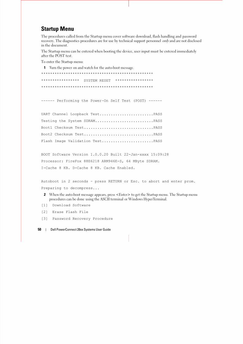
8/21/2019 Powerconnect-2824 User's Guide en-us
http://slidepdf.com/reader/full/powerconnect-2824-users-guide-en-us 50/184
50 Dell PowerConnect 28xx Systems User Guide
Startup MenuThe procedures called from the Startup menu cover software download, flash handling and password
recovery. The diagnostics procedures are for use by technical support personnel only and are not disclosedin the document.
The Startup menu can be entered when booting the device, user input must be entered immediatelyafter the POST test.
To enter the Startup menu:
1 Turn the power on and watch for the auto-boot message.
******************************************************************* SYSTEM RESET *****************
**************************************************
------ Performing the Power-On Self Test (POST) ------
UART Channel Loopback Test........................PASS
Testing the System SDRAM..........................PASS
Boot1 Checksum Test...............................PASS
Boot2 Checksum Test...............................PASS
Flash Image Validation Test.......................PASS
BOOT Software Version 1.0.0.20 Built 22-Jan-xxxx 15:09:28
Processor: FireFox 88E6218 ARM946E-S, 64 MByte SDRAM.
I-Cache 8 KB. D-Cache 8 KB. Cache Enabled.
Autoboot in 2 seconds - press RETURN or Esc. to abort and enter prom.
Preparing to decompress...
2 When the auto-boot message appears, press <Enter> to get the Startup menu. The Startup menuprocedures can be done using the ASCII terminal or Windows HyperTerminal.
[1] Download Software
[2] Erase Flash File
[3] Password Recovery Procedure
[4] Enter Diagnostic Mode
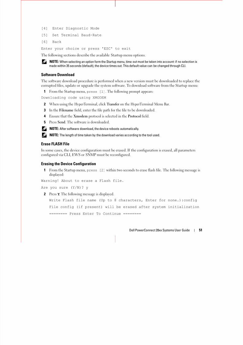
8/21/2019 Powerconnect-2824 User's Guide en-us
http://slidepdf.com/reader/full/powerconnect-2824-users-guide-en-us 51/184
Dell PowerConnect 28xx Systems User Guide 51
g
[5] Set Terminal Baud-Rate
[6] Back
Enter your choice or press 'ESC' to exit
The following sections describe the available Startup menu options.
NOTE: When selecting an option form the Startup menu, time out must be taken into account: if no selection is
made within 35 seconds (default), the device times out. This default value can be changed through CLI.
Software DownloadThe software download procedure is performed when a new version must be downloaded to replace thecorrupted files, update or upgrade the system software. To download software from the Startup menu:
1 From the Startup menu, press [1]. The following prompt appears:
Downloading code using XMODEM
2 When using the HyperTerminal, click Transfer on the HyperTerminal Menu Bar.
3 In the Filename field, enter the file path for the file to be downloaded.4 Ensure that the Xmodem protocol is selected in the Protocol field.
5 Press Send. The software is downloaded.
NOTE: After software download, the device reboots automatically.
NOTE: The length of time taken by the download varies according to the tool used.
Erase FLASH File
In some cases, the device configuration must be erased. If the configuration is erased, all parametersconfigured via CLI, EWS or SNMP must be reconfigured.
Erasing the Device Configuration
1 From the Startup menu, press [2] within two seconds to erase flash file. The following message isdisplayed:
Warning! About to erase a Flash file.Are you sure (Y/N)? y
2 Press Y. The following message is displayed.
Write Flash file name (Up to 8 characters, Enter for none.):config
File config (if present) will be erased after system initialization
======== Press Enter To Continue ========
3 Enter config as the name of the flash file. The configuration is erased and the device reboots.

8/21/2019 Powerconnect-2824 User's Guide en-us
http://slidepdf.com/reader/full/powerconnect-2824-users-guide-en-us 52/184
52 Dell PowerConnect 28xx Systems User Guide
4 Repeat the device initial configuration.
Password Recovery
If a password is lost, the Password Recovery procedure can be called from the Startup menu. Theprocedure enables entry to the device once without a password.
To recover a lost password for the local terminal only:
1 From the Startup menu, type 3 and press <Enter>.
The password is deleted.
NOTE: To ensure device security, reconfigure passwords for applicable management methods.
Software Download Through TFTP Server
This section contains instructions for downloading device software (system and boot images) through aTFTP server. The TFTP server must be configured before beginning to download the software.
System Image Download
The device boots and runs when decompressing the system image from the flash memory area where acopy of the system image is stored. When a new image is downloaded, it is saved in the other areaallocated for the other system image copy.
On the next boot, the device will decompress and run the currently active system image unless chosenotherwise.
To download a system image through the TFTP server:
1Ensure that an IP address is configured on one of the device ports and pings can be sent to a TFTPserver.
2 Make sure that the file to be downloaded is saved on the TFTP server (the ros file).
3 Enter copy tftp://{tftp address}/{file name} image to copy a new system image to thedevice. When the new image is downloaded, it is saved in the area allocated for the other copy of systemimage. The following is an example of the information that appears:
console# copy tftp://176.215.31.3/file1.ros image
Accessing file ‘file1’ on 176.215.31.3ÖLoading file1 from 176.215.31.3:
!!!!!!!!!!!!!!!!!!!!!!!!!!!!!!!!!!!!!!!!!!!!!!!!!!!!!!!!!!!!!!!!!!!!!!!!!!!!!!!!!!!!!!!!!!!!!!!!!!!!!!!!!!!!!!!!!!!!!!!!!!!!!!!!!!!!
Copy took 00:01:11 [hh:mm:ss]
Exclamation symbols indicate that a copying process is in progress. Each symbol (!) corresponds to512 bytes transferred successfully. A period indicates that the copying process is timed out. Manyperiods in a row indicate that the copying process failed.
4 Enter the reload command. The following message is displayed:
8/21/2019 Powerconnect-2824 User's Guide en-us
http://slidepdf.com/reader/full/powerconnect-2824-users-guide-en-us 53/184
Dell PowerConnect 28xx Systems User Guide 53
console# reload
This command will reset the whole system and disconnect your currentsession. Do you want to continue (y/n) [n]?
5 Enter y. The device reboots.
Boot Image Download
Loading a new boot image from the TFTP server and programming it into the flash updates the bootimage. The boot image is loaded when the device is powered on. A user has no control over the boot
image copies. To download a boot image through the TFTP server:1 Ensure that an IP address is configured on one of the device ports and pings can be sent to a
TFTP server.
2 Ensure that the file to be downloaded is saved on the TFTP server (the rfb file).
3 Enter copy tftp://{tftp address}/{file name} boot to copy the boot image to thedevice. The following is an example of the information that appears:
console# copy tftp://176.215.31.3/332448-10018.rfb boot
Erasing file..done.
!!!!!!!!!!!!!!!!!!!!!!!!!!!!!!!!!!!!!!!!!!!!!!!!!!!!!!!!!!!!!!!!!!!!!!!!!!!!!!!!!!!!!!!!!!!!!!!!!!!!!!!!!!!!!!!!!!!!!!!!!!!!!!!!!!!!
Copy: 2739187 bytes copied in 00:01:13 [hh:mm:ss]
4 Enter the reload command. The following message is displayed:
console# reloadThis command will reset the whole system and disconnect your current
session. Do you want to continue (y/n) [n]?
5 Enter y.
The device reboots.
5
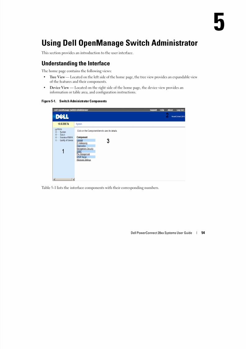
8/21/2019 Powerconnect-2824 User's Guide en-us
http://slidepdf.com/reader/full/powerconnect-2824-users-guide-en-us 54/184
Dell PowerConnect 28xx Systems User Guide 54
Using Dell OpenManage Switch AdministratorThis section provides an introduction to the user interface.
Understanding the InterfaceThe home page contains the following views:
• Tree View — Located on the left side of the home page, the tree view provides an expandable viewof the features and their components.
• Device View — Located on the right side of the home page, the device view provides aninformation or table area, and configuration instructions.
Figure 5-1. Switch Administrator Components
Table 5-1 lists the interface components with their corresponding numbers.
Table 5-1. Interface Components
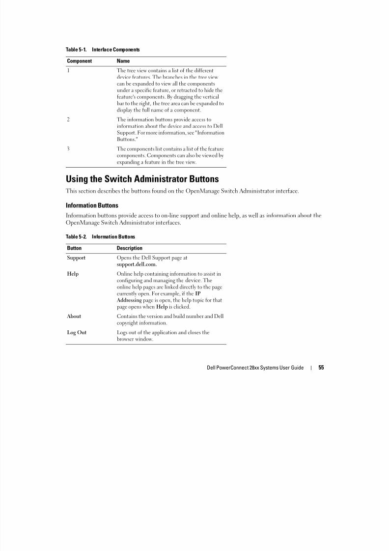
8/21/2019 Powerconnect-2824 User's Guide en-us
http://slidepdf.com/reader/full/powerconnect-2824-users-guide-en-us 55/184
Dell PowerConnect 28xx Systems User Guide 55
Using the Switch Administrator ButtonsThis section describes the buttons found on the OpenManage Switch Administrator interface.
Information Buttons
Information buttons provide access to on-line support and online help, as well as information about theOpenManage Switch Administrator interfaces.
p
Component Name
1 The tree view contains a list of the differentdevice features. The branches in the tree viewcan be expanded to view all the componentsunder a specific feature, or retracted to hide thefeature's components. By dragging the verticalbar to the right, the tree area can be expanded todisplay the full name of a component.
2 The information buttons provide access toinformation about the device and access to DellSupport. For more information, see "InformationButtons."
3 The components list contains a list of the featurecomponents. Components can also be viewed byexpanding a feature in the tree view.
Table 5-2. Information Buttons
Button Description
Support Opens the Dell Support page atsupport.dell.com.
Help Online help containing information to assist inconfiguring and managing the device. Theonline help pages are linked directly to the pagecurrently open. For example, if the IPAddressing page is open, the help topic for thatpage opens when Help is clicked.
About Contains the version and build number and Dellcopyright information.
Log Out Logs out of the application and closes thebrowser window.
Device Management Buttons
D M b d h d f f d f d l d

8/21/2019 Powerconnect-2824 User's Guide en-us
http://slidepdf.com/reader/full/powerconnect-2824-users-guide-en-us 56/184
56 Dell PowerConnect 28xx Systems User Guide
Device Management buttons provide an easy method of configuring device information, and includes
the following:
Starting the Application1 Open a web browser.
2 Enter the device’s IP address (as defined in the CLI) in the address bar and press <Enter>.
For information about assigning an IP address to a device, see "Static IP Address and Subnet Mask."
3 When the Enter Network Password window opens, enter a user name and password.
NOTE: The device is not configured with a default password, and can be configured without entering a
password. For information about recovering a lost password, see “Password Recovery.
NOTE: Passwords are both case sensitive and alpha-numeric.
NOTE: The device can be managed via web interface only in Managed mode. For more information about
management modes, see "Management Modes" on page 51.
4 Click OK.
The Dell PowerConnect OpenManage™ Switch Administrator home page opens.
Access Levels
When you login to the device, you are automatically assigned one of the following modes, based uponthe access level assigned to you:
Table 5-3. Device Management Buttons
Button Description
Apply Changes Applies changes to the device.
Add Adds information to tables or dialogs.
Telnet Starts a Telnet session.
Query Queries tables.
Show All Displays the device tables.
Left arrow/Right arrow Moves information between lists.
Refresh Refreshes device information.
Reset All Counters Clears statistic counters.
Print Prints the Network Management System page and/ortable information.
Draw Creates statistics charts on-the-fly.
• Management — This is a read-write mode where you can see and edit all pages of the interface.
• Mo ito This is a read o l ode here o ca see a s bset of the i terface ages b t o ca ot

8/21/2019 Powerconnect-2824 User's Guide en-us
http://slidepdf.com/reader/full/powerconnect-2824-users-guide-en-us 57/184
Dell PowerConnect 28xx Systems User Guide 57
• Monitor — This is a read-only mode where you can see a subset of the interface pages, but you cannot
edit them.For more information about setting the access level, see ("Defining the Local User Databases" onpage 68).
6
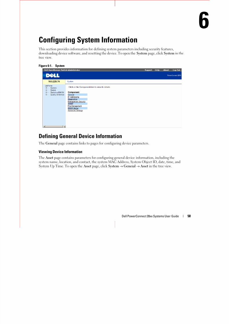
8/21/2019 Powerconnect-2824 User's Guide en-us
http://slidepdf.com/reader/full/powerconnect-2824-users-guide-en-us 58/184
Dell PowerConnect 28xx Systems User Guide 58
Configuring System InformationThis section provides information for defining system parameters including security features,downloading device software, and resetting the device. To open the System page, click System in thetree view.
Figure 6-1. System
Defining General Device InformationThe General page contains links to pages for configuring device parameters.
Viewing Device Information
The Asset page contains parameters for configuring general device information, including thesystem name, location, and contact, the system MAC Address, System Object ID, date, time, andSystem Up Time. To open the Asset page, click System General Asset in the tree view.
Figure 6-2. Asset
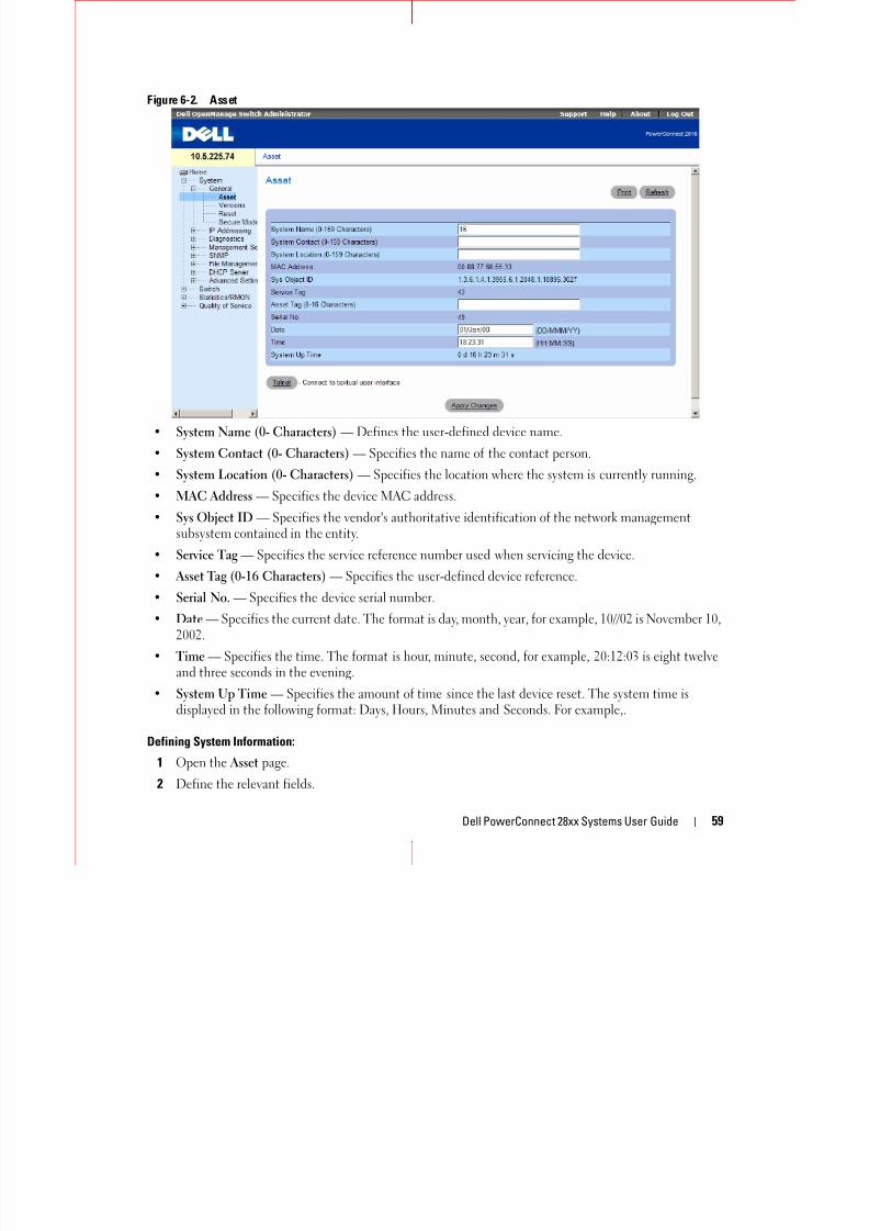
8/21/2019 Powerconnect-2824 User's Guide en-us
http://slidepdf.com/reader/full/powerconnect-2824-users-guide-en-us 59/184
Dell PowerConnect 28xx Systems User Guide 59
• System Name (0- Characters) — Defines the user-defined device name.
• System Contact (0- Characters) — Specifies the name of the contact person.
• System Location (0- Characters) — Specifies the location where the system is currently running.
• MAC Address — Specifies the device MAC address.
• Sys Object ID — Specifies the vendor's authoritative identification of the network managementsubsystem contained in the entity.
• Service Tag — Specifies the service reference number used when servicing the device.
• Asset Tag (0-16 Characters) — Specifies the user-defined device reference.
• Serial No. — Specifies the device serial number.
• Date — Specifies the current date. The format is day, month, year, for example, 10//02 is November 10,2002.
• Time — Specifies the time. The format is hour, minute, second, for example, 20:12:03 is eight twelveand three seconds in the evening.
• System Up Time — Specifies the amount of time since the last device reset. The system time isdisplayed in the following format: Days, Hours, Minutes and Seconds. For example,.
Defining System Information:
1 Open the Asset page.
2 Define the relevant fields.
3 Click Apply Changes.
The system parameters are defined, and the device is updated.
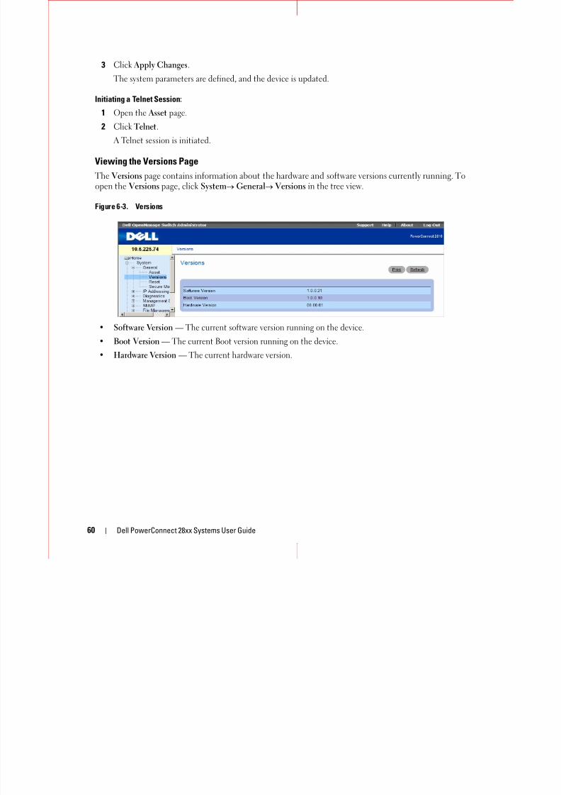
8/21/2019 Powerconnect-2824 User's Guide en-us
http://slidepdf.com/reader/full/powerconnect-2824-users-guide-en-us 60/184
60 Dell PowerConnect 28xx Systems User Guide
y p , p
Initiating a Telnet Session:
1 Open the Asset page.
2 Click Telnet.
A Telnet session is initiated.
Viewing the Versions Page
The Versions page contains information about the hardware and software versions currently running. Toopen the Versions page, click System General Versions in the tree view.
Figure 6-3. Versions
• Software Version — The current software version running on the device.
• Boot Version — The current Boot version running on the device.
• Hardware Version — The current hardware version.
Resetting the Device
The Reset page enables the device to be reset from a remote location. For more information about saved

8/21/2019 Powerconnect-2824 User's Guide en-us
http://slidepdf.com/reader/full/powerconnect-2824-users-guide-en-us 61/184
Dell PowerConnect 28xx Systems User Guide 61
p g
Configuration files, see "Managing Files" on page 79. To open the Reset page , click System
General
Reset in the tree view.
Figure 6-4. Reset
Resetting the Device
1 Open the Reset page2 Click reset.
A confirmation message displays.
3 Click OK.
The device is reset. After the device is reset, a prompt for a user name and password displays.
4 Enter a user name and password to reconnect to the Web Interface.
Entering Secure Mode
The Secure Mode page allows you to put the device in the Secure management mode. Once enabled, it

8/21/2019 Powerconnect-2824 User's Guide en-us
http://slidepdf.com/reader/full/powerconnect-2824-users-guide-en-us 62/184
62 Dell PowerConnect 28xx Systems User Guide
g g
prevents users from making any further configuration changes to the switch. This is done by removingthe IP address of the switch so that it becomes inaccessible. In Secure Mode the switch retainsconfiguration through power cycles just like in Managed Mode.
To use Secure Mode, configure the device in Managed Mode, and then switch to Secure Mode via theweb interface. To exit Secure Mode, press the Managed Mode button on the device to enter theManaged Mode. For information about management modes, see "Management Modes" on page 50. Forinformation about saving Configuration files, see "Managing Files" on page 79.
To open the Secure Mode page , click System General Secure Mode in the tree view.
Figure 6-5. Secure Mode
Entering Secure Mode
1 Open the Secure Mode page.
2 Click Secure.
A confirmation message displays.
3 Click OK.
The device enters Secure mode.
Defining Device IP AddressesThe IP Addressing page contains a link to the IP Interface Parameters page that is used to assign the

8/21/2019 Powerconnect-2824 User's Guide en-us
http://slidepdf.com/reader/full/powerconnect-2824-users-guide-en-us 63/184
Dell PowerConnect 28xx Systems User Guide 63
The IP Addressing page contains a link to the IP Interface Parameters page that is used to assign the
device IP address, subnet mask and default gateway, and for enabling or disabling DHCP.To open the IP Addressing page, click System IP Addressing in the tree view.
Defining IP Interface Parameters
To open the IP Interface Parameters page, click System IP Addressing IP Interface Parameters inthe tree view.
Figure 6-6. IP Interface Parameters
• DHCP — The DHCP client can be enabled to acquire the network configuration dynamically. TheDHCP default value is Disable. This field enables the DHCP client.
• IP Address — Specifies the IP Address currently assigned to the device.
• Subnet Mask— Specifies the subnet mask of the IP Address, currently assigned to the device.
• Default Gateway — Specifies the Default Gateway Address, currently assigned to the device.
Setting static IP Interface parameters:
1 Open the IP Interface Parameters page.
2 Set the IP Address, Subnet Mask and Default Gateway.
3 Click Apply Changes.
The static interface parameters are set and the device is updated.
Running Cable DiagnosticsThe Diagnostics section contains links to pages for performing virtual cable tests on copper cables and

8/21/2019 Powerconnect-2824 User's Guide en-us
http://slidepdf.com/reader/full/powerconnect-2824-users-guide-en-us 64/184
64 Dell PowerConnect 28xx Systems User Guide
g p g p g pp
optical transceivers. To open the Diagnostics page, click System Diagnostics in the tree view.• Viewing Optical Transceiver Diagnostics (Applicable only for 24, 48 port devices)
Viewing Copper Cable Diagnostics
The Integrated Cable Test for Copper Cables page contains fields for performing tests on copper cables.Cable testing provides information about where errors occurred in the cable, the last time a cable testwas performed, and the type of cable error which occurred. The tests use Time Domain Reflectometry
(TDR) technology to test the quality and characteristics of a copper cable attached to a port. Cables upto meters long can be tested. Cables are tested when the ports are in the down state, with the exceptionof the Approximated Cable Length test. The cable length returned is an approximation in the ranges ofup to 50 meters, 50m-80m, 80m-110m, 110m-m, or more than m. The deviation may be up to 20 meters.
To open the Integrated Cable Test for Copper Cables page, click System Diagnostics IntegratedCable Test in the tree view.
Figure 6-7. Integrated Cable Test for Copper Cables
• Port — The port to which the cable is connected.
• Test Result — The cable test results. Possible values are:
– No Cable —
– Open Cable — cable is connected on only one side.
– Short Cable — OK — The cable passed the test.
• Cable Fault Distance — The distance from the port where the cable error occurred.
• Last Update — The last time the port was tested.

8/21/2019 Powerconnect-2824 User's Guide en-us
http://slidepdf.com/reader/full/powerconnect-2824-users-guide-en-us 65/184
Dell PowerConnect 28xx Systems User Guide 65
• Approximate Cable Length — The approximate cable length. This test can only be performed whenthe port is up and operating at 1 Gbps.
Performing a Cable Test
1 Ensure that both ends of the copper cable are connected to a device.
2 Open the Integrated Cable Test page.
3 Click Test Now.
The copper cable test is performed, and the results are displayed on the Integrated Cable Test forCopper Cables page.
Displaying Virtual Cable Test Results Table
1 Open the Integrated Cable Test for Copper Cables page.
2 Click Show All.
The Virtual Cable Test Results Table opens.
Viewing Optical Transceiver Diagnostics
The Optical Transceiver Diagnostics page contains fields for performing tests on Fiber Optic cables.Optical transceiver diagnostics can be performed only when the link is present. To open the OpticalTransceiver Diagnostics page, click SystemDiagnostics Optical Transceiver Diagnostics in the treeview.
Figure 6-8. Optical Transceiver Diagnostics
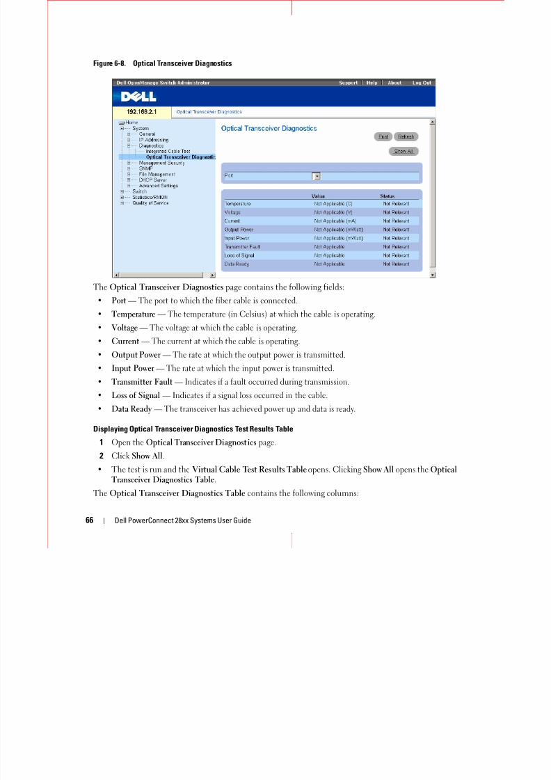
8/21/2019 Powerconnect-2824 User's Guide en-us
http://slidepdf.com/reader/full/powerconnect-2824-users-guide-en-us 66/184
66 Dell PowerConnect 28xx Systems User Guide
The Optical Transceiver Diagnostics page contains the following fields:
• Port — The port to which the fiber cable is connected.
• Temperature — The temperature (in Celsius) at which the cable is operating.
• Voltage — The voltage at which the cable is operating.
• Current — The current at which the cable is operating.
• Output Power — The rate at which the output power is transmitted.
• Input Power — The rate at which the input power is transmitted.
• Transmitter Fault — Indicates if a fault occurred during transmission.
• Loss of Signal — Indicates if a signal loss occurred in the cable.
• Data Ready — The transceiver has achieved power up and data is ready.
Displaying Optical Transceiver Diagnostics Test Results Table
1 Open the Optical Transceiver Diagnostics page.
2 Click Show All.
• The test is run and the Virtual Cable Test Results Table opens. Clicking Show All opens the OpticalTransceiver Diagnostics Table.
The Optical Transceiver Diagnostics Table contains the following columns:
• Port — The port to which the fiber cable is connected.
• Temperature — Internally measured transceiver temperature.

8/21/2019 Powerconnect-2824 User's Guide en-us
http://slidepdf.com/reader/full/powerconnect-2824-users-guide-en-us 67/184
Dell PowerConnect 28xx Systems User Guide 67
• Voltage — Internally measured supply voltage.• Current — Measured TX bias current.
• Output Power — Measured TX output power in milliwatts.
• Input Power — Measured RX received power in milliwatts.
• TXTransmitter Fault — Transmitter fault.
Finisair transceivers do not support the transmitter fault diagnostic testing.
• LOSLoss of Signal — Loss of signal.• Data Ready — The transceiver has archived power up and data is ready.
• N/A — Not Available, N/S - Not Supported, W - Warning, E - Error.
Fiber Optic analysis feature works only on SFPs that support the digital diagnostic standard SFF-4872.
Managing Device SecurityThe Management Security page provides access to security pages that contain fields for setting security
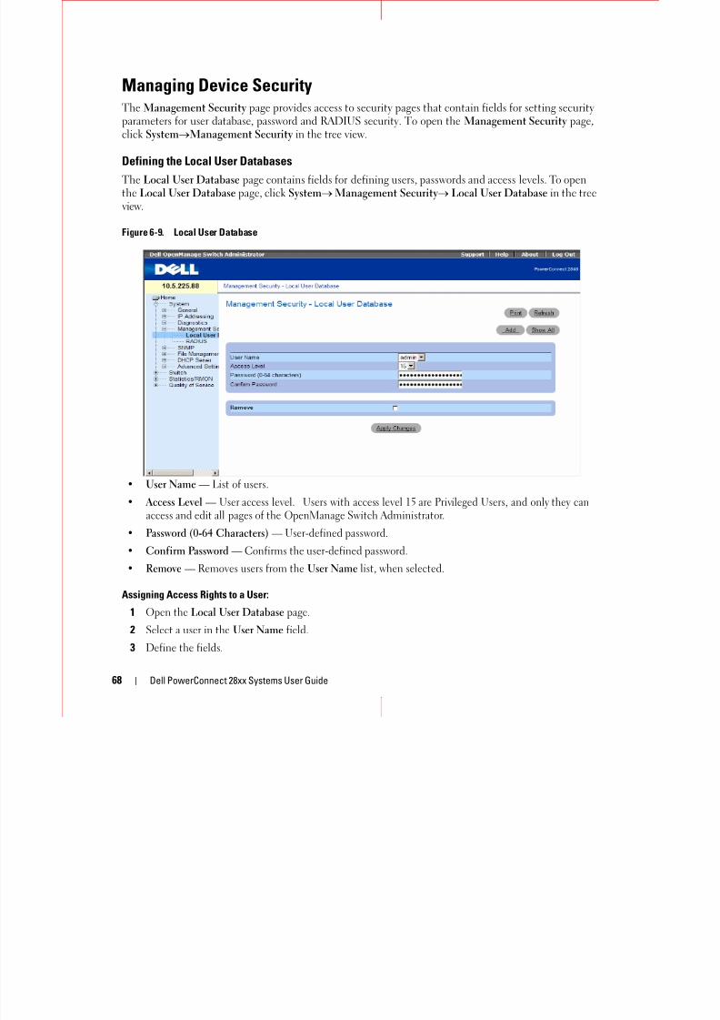
8/21/2019 Powerconnect-2824 User's Guide en-us
http://slidepdf.com/reader/full/powerconnect-2824-users-guide-en-us 68/184
68 Dell PowerConnect 28xx Systems User Guide
parameters for user database, password and RADIUS security. To open the Management Security page ,click SystemManagement Security in the tree view.
Defining the Local User Databases
The Local User Database page contains fields for defining users, passwords and access levels. To openthe Local User Database page, click System Management Security Local User Database in the treeview.
Figure 6-9. Local User Database
• User Name — List of users.
• Access Level — User access level. Users with access level 15 are Privileged Users, and only they canaccess and edit all pages of the OpenManage Switch Administrator.
• Password (0-64 Characters) — User-defined password.
• Confirm Password — Confirms the user-defined password.
• Remove — Removes users from the User Name list, when selected.
Assigning Access Rights to a User:
1 Open the Local User Database page.
2 Select a user in the User Name field.
3 Define the fields.
4 Click Apply Changes.
The user access rights and passwords are defined, and the device is updated.
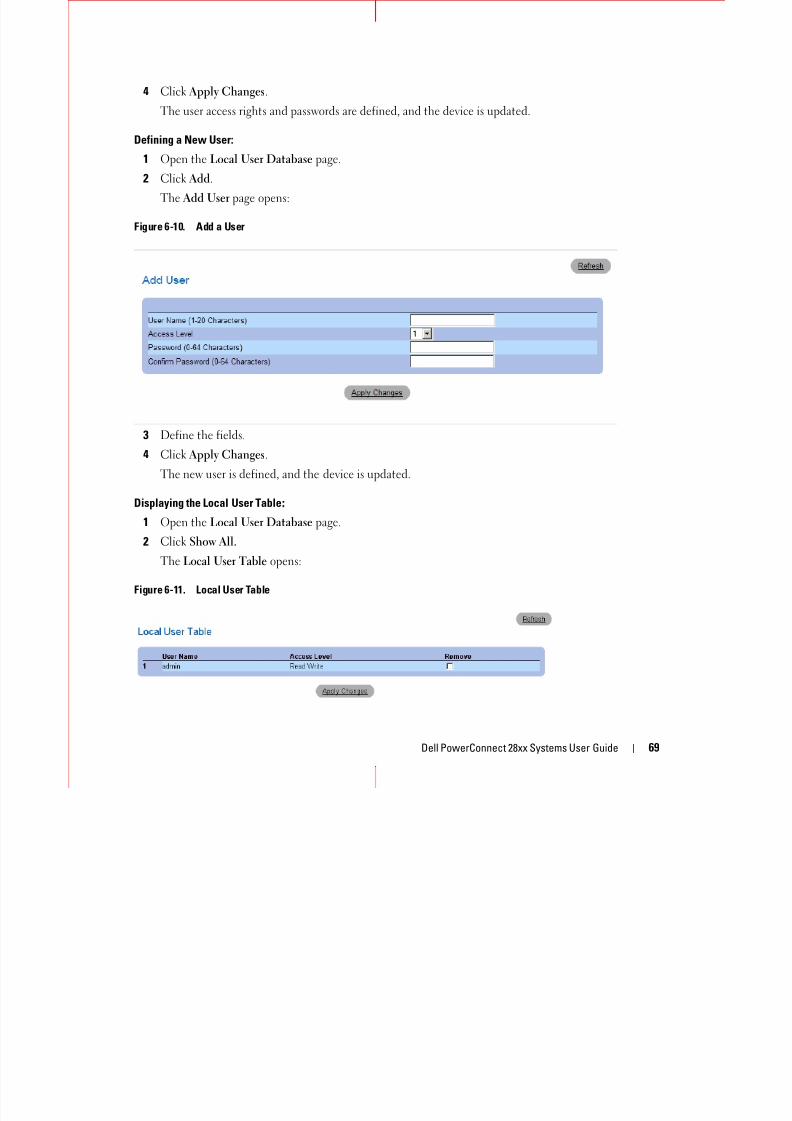
8/21/2019 Powerconnect-2824 User's Guide en-us
http://slidepdf.com/reader/full/powerconnect-2824-users-guide-en-us 69/184
Dell PowerConnect 28xx Systems User Guide 69
Defining a New User:
1 Open the Local User Database page.
2 Click Add.
The Add User page opens:
Figure 6-10. Add a User
3 Define the fields.
4 Click Apply Changes.
The new user is defined, and the device is updated.
Displaying the Local User Table
1 Open the Local User Database page.
2 Click Show All.
The Local User Table opens:
Figure 6-11. Local User Table
Deleting Users:
1 Open the Local User Database page.
Cl k Sh All

8/21/2019 Powerconnect-2824 User's Guide en-us
http://slidepdf.com/reader/full/powerconnect-2824-users-guide-en-us 70/184
70 Dell PowerConnect 28xx Systems User Guide
2 Click Show All.The Local User Table opens.
3 Select a User Name.
4 Select the Remove check box.
5 Click Apply Changes.
The selected user is deleted and the device is updated.
Configuring RADIUS Global Parameters
Remote Authorization Dial-In User Service (RADIUS) servers provide additional security for networks.
To open the RADIUS Settings page, click System Management Security RADIUS in the tree view.
Figure 6-12. RADIUS Settings
• IP Address — The list of Authentication Server IP addresses.
• Priority (0-65535) — Specifies the server priority. The possible values are 0-65535, where 0 is thehighest value. This is used to configure the order in which servers are queried.
• Authentication Port — Identifies the authentication port. The authentication port is used to verifythe RADIUS server authentication.
• Number of Retries (1-10) — Specifies the number of transmitted requests sent to RADIUS serverb f f il Th ibl fi ld l 1 10 Th i th d f lt l

8/21/2019 Powerconnect-2824 User's Guide en-us
http://slidepdf.com/reader/full/powerconnect-2824-users-guide-en-us 71/184
Dell PowerConnect 28xx Systems User Guide 71
before a failure occurs. The possible field values are 1 - 10. Three is the default value.
• Timeout for Reply (1-30) — Specifies the amount of the time in seconds the device waits for ananswer from the RADIUS server before retrying the query, or switching to the next server. The possiblefield values are 1 - 30. The default is 3.
• Dead Time (0-2000) — Specifies the amount of time (in seconds) that a RADIUS server is bypassedfor service requests. The range is 0-2000.
• Key String (0-128 Characters) — Specifies the Key string used for authenticating and encrypting allRADIUS communications between the device and the RADIUS server. This key is encrypted.
• Source IP Address — Specifies the source IP address that is used for communication with RADIUSservers.
If host-specific Timeouts, Retries, or Dead time values are not specified, the Global values (Defaults) areapplied to each host. The following fields set the RADIUS default values:
• Default Retries (1-10) — Specifies the default number of transmitted requests sent to RADIUS server
before a failure occurs.• Default Timeout for Reply (1-30) — Specifies the default amount of the time (in seconds) the device
waits for an answer from the RADIUS server before timing out.
• Default Dead time (0-2000) — Specifies the default amount of time (in seconds) that a RADIUSserver is bypassed for service requests. The range is 0-2000.
• Default Key String (0-128 Characters) — Specifies the Default Key string used for authenticating andencrypting all RADIUS communications between the device and the RADIUS server. This key is
encrypted.• Source Address — Specifies the source IP address that is used for communication with RADIUS
servers.
Defining RADIUS Parameters:
1 Open the RADIUS Settings page.
2 Define the fields.
3 Click Apply Changes.The RADIUS setting are updated to the device.
Adding a RADIUS Server:
1 Open the RADIUS Settings page.
2 Click Add.
The Add RADIUS Server page opens:
Figure 6-13. Add RADIUS Server Page
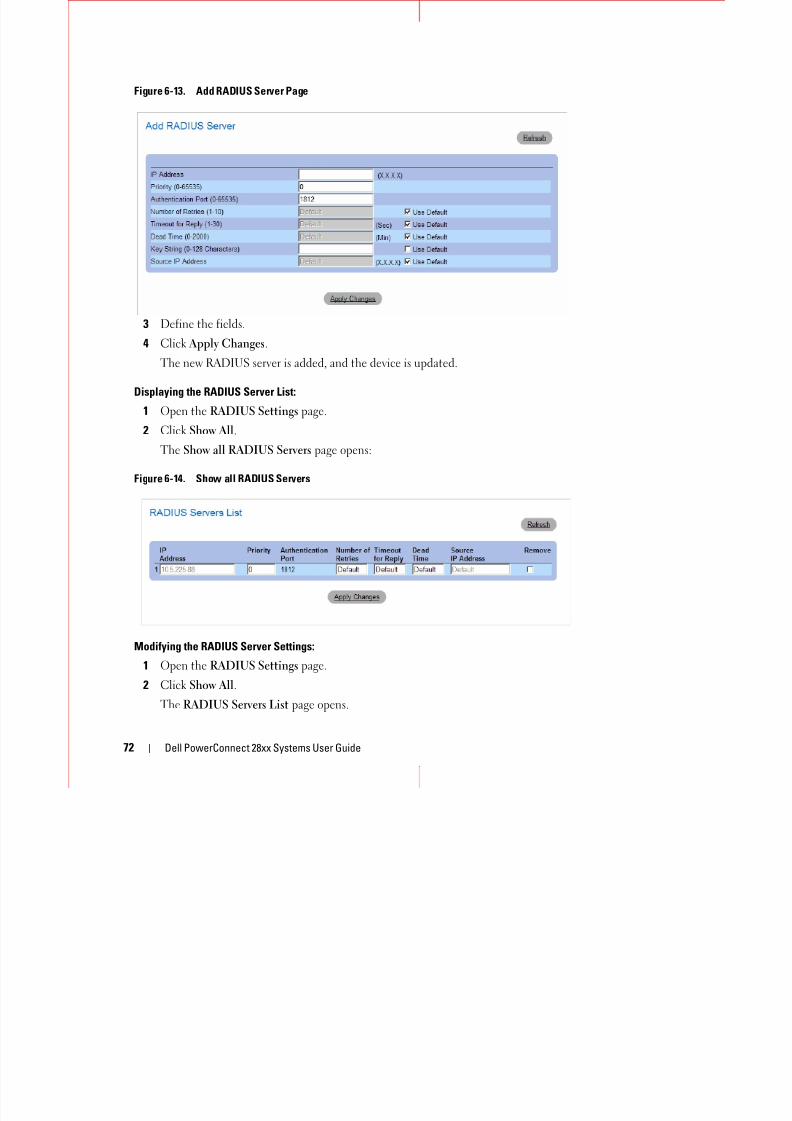
8/21/2019 Powerconnect-2824 User's Guide en-us
http://slidepdf.com/reader/full/powerconnect-2824-users-guide-en-us 72/184
72 Dell PowerConnect 28xx Systems User Guide
3 Define the fields.
4 Click Apply Changes.
The new RADIUS server is added, and the device is updated.
Displaying the RADIUS Server List:
1 Open the RADIUS Settings page.
2 Click Show All.
The Show all RADIUS Servers page opens:
Figure 6-14. Show all RADIUS Servers
Modifying the RADIUS Server Settings:
1 Open the RADIUS Settings page.
2 Click Show All.
The RADIUS Servers List page opens.
3 Modify the relevant fields.
4 Click Apply Changes.
The RADIUS Server settings are modified and the device is updated

8/21/2019 Powerconnect-2824 User's Guide en-us
http://slidepdf.com/reader/full/powerconnect-2824-users-guide-en-us 73/184
Dell PowerConnect 28xx Systems User Guide 73
The RADIUS Server settings are modified, and the device is updated.
Deleting a RADIUS Server for the RADIUS Servers List:
1 Open the RADIUS Settings page.
2 Click Show All.
The RADIUS Servers List page opens.
3 Select a RADIUS Server in the RADIUS Servers List.
4 Select the Remove check box.
5 Click Apply Changes.
The RADIUS server is removed from the RADIUS Servers List.
Defining SNMP ParametersSimple Network Management Protocol (SNMP) provides a method for managing network devices.Devices supporting SNMP run a local software (agent).
The SNMP agents maintain a list of variables, which are used to manage the device. The variables aredefined in the Management Information Base (MIB). The MIB contains the variables controlled by theagent. The SNMP protocol defines the MIB specification format, as well as the format used to access theinformation over the network.
Access rights to the SNMP agents are controlled by access strings. To communicate with the device, theEmbedded Web Server submits a valid community string for authentication. To open the SNMP page,
click System SNMP in the tree view.This section contains information for managing the SNMP configuration.
Defining SNMP Global Parameters
The SNMP Global Parameters page permits enabling both SNMP and Authentication notifications.Toopen the SNMP Global Parameters page, click System SNMP Global Parameters in the tree view.

8/21/2019 Powerconnect-2824 User's Guide en-us
http://slidepdf.com/reader/full/powerconnect-2824-users-guide-en-us 74/184
74 Dell PowerConnect 28xx Systems User Guide
Figure 6-15. Global Parameters
• SNMP Notifications — Enables or disables the sending SNMP notifications.
• Authentication Notifications — Enables or disables the sending SNMP traps when authenticationfails.
Enabling SNMP Notifications
1 Open the SNMP Global Parameters page.
2 Select Enable in the SNMP Notifications field.3 Click Apply Changes.
SNMP notifications are enabled, and the device is updated.
Enabling Authentication Notifications
1 Open the SNMP Global Parameters page.
2 Select Enable in the Authentication Notifications field.
3 Click Apply Changes.
Defining Communities
Access rights are managed by defining communities in the Community Table. When the communitynames are changed, access rights are also changed.To open the SNMP Community page, click SystemSNMPCommunity in the tree view.

8/21/2019 Powerconnect-2824 User's Guide en-us
http://slidepdf.com/reader/full/powerconnect-2824-users-guide-en-us 75/184
Dell PowerConnect 28xx Systems User Guide 75
SNMP Community in the tree view.
Figure 6-16. SNMP Community
• SNMP Management Station — A list of management station IP addresses.
• Community String — Functions as a password and used to authenticate the selected managementstation to the device.
• Access Mode — Defines the access rights of the community. The possible field values are:
– Read Only — The management access is restricted to read-only, for all MIBs except thecommunity table, for which there is no access.
– Read Write — The management access is read-write, for all MIBs except the community table, forwhich there is no access.
– SNMP Admin — The management access is read-write for all MIBs, including the communitytable.
• Remove — Removes a community, when selected.
Defining a New Community
1 Open the SNMP Community page.
2 Click Add.
The Add SNMP Community page opens:
Figure 6-17. Add SNMP Community

8/21/2019 Powerconnect-2824 User's Guide en-us
http://slidepdf.com/reader/full/powerconnect-2824-users-guide-en-us 76/184
76 Dell PowerConnect 28xx Systems User Guide
3 Select one of the following:
– SNMP Management Station — Defines an SNMP community for a specific management station.
– All — Defines an SNMP community for all management stations.
4 Define the remaining fields.
5 Click Apply Changes.
The new community is saved, and the device is updated.
Displaying all Communities
1 Open the SNMP Community page.
2 Click Show All.
The Community Table opens:
Figure 6-18. Community Table
Deleting Communities
1 Open the Community Table page.
2 Click Show All.
The Community Table opens.
3 Select a community from the Community Table.
4 Select the Remove check box.
5Click Apply Changes.The selected community entry is deleted and the device is updated

8/21/2019 Powerconnect-2824 User's Guide en-us
http://slidepdf.com/reader/full/powerconnect-2824-users-guide-en-us 77/184
Dell PowerConnect 28xx Systems User Guide 77
gThe selected community entry is deleted, and the device is updated.
Defining SNMP Notification Recipients
The Notification Recipients page contains information for defining filters that determine whether trapsare sent to specific users, and the trap type sent. SNMP notification filters provide the following services:
• Identifying Management Trap Targets
• Trap Filtering• Selecting Trap Generation Parameters
• Providing Access Control Checks
To open the Notification Recipients page, click System SNMP Notification Recipient in thetree view.
Figure 6-19. Notification Recipients
• Recipient IP — Indicates the IP address to whom the traps are sent.
•
• Notification Version — Determines the trap type. The possible field values are:
– SNMPv1 — SNMP Version 1 traps are sent.
– SNMPv2 — SNMP Version 2 traps are sent.
• Remove Notification Recipient — When checked, removes selected notification recipients.
Adding a new Trap Recipients
1 Open Notification Recipients page.
2 Click Add.
The Add Notification Recipients page opens:

8/21/2019 Powerconnect-2824 User's Guide en-us
http://slidepdf.com/reader/full/powerconnect-2824-users-guide-en-us 78/184
78 Dell PowerConnect 28xx Systems User Guide
The Add Notification Recipients page opens:
3 Define the relevant fields.
4 Click Apply Changes.
The notification recipient is added, and the device is updated.
Displaying Notification Recipients Tables1 Open Notification Recipients page.
2 Click Show All.
The Notification Recipients Tables page opens:
Figure 6-20. Notification Recipients Tables
Deleting Notification Recipients
1 Open Notification Recipients page.
2 Click Show All.
The Notification Recipients Tables page opens.
3Select a notification recipient.
4 Check the Remove checkbox.
5 Click Apply Changes. The recipient is deleted, and the device is updated.
Managing Files
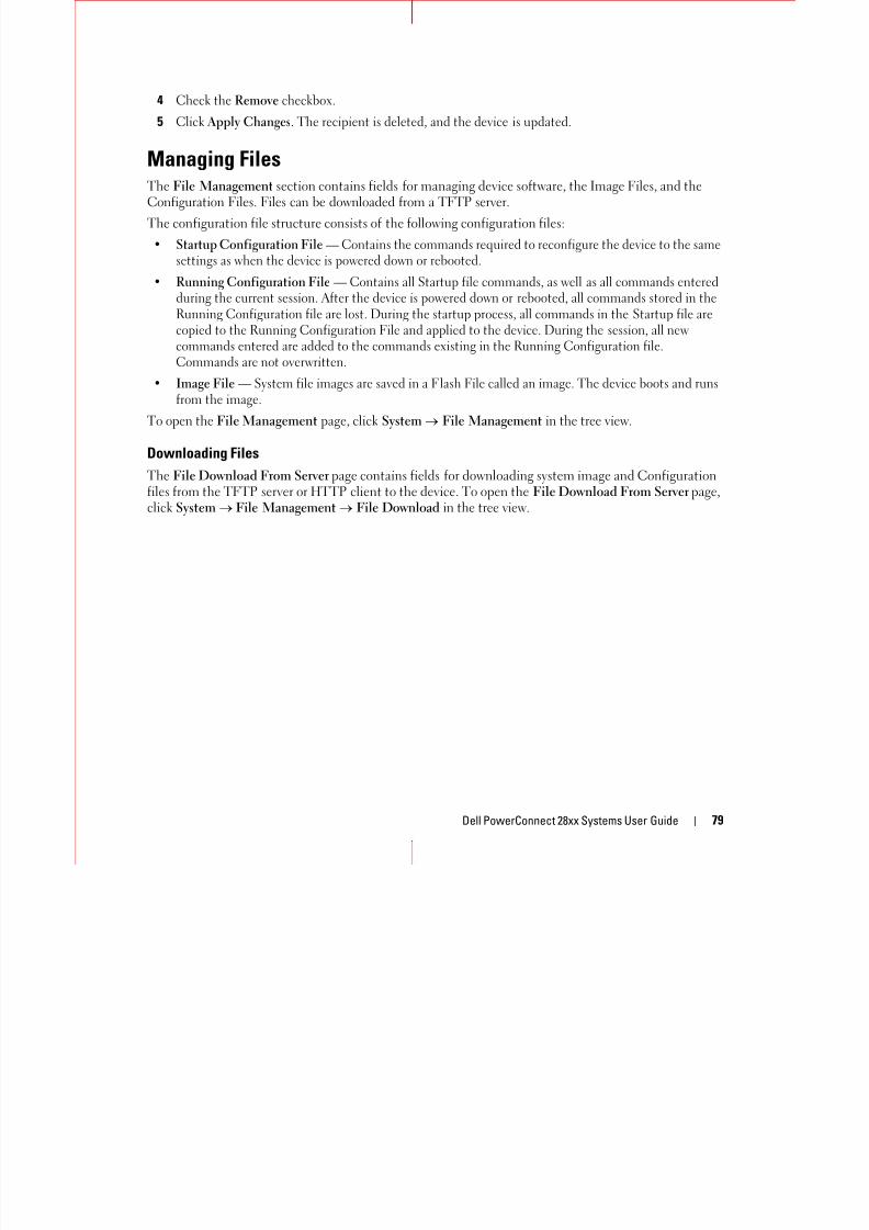
8/21/2019 Powerconnect-2824 User's Guide en-us
http://slidepdf.com/reader/full/powerconnect-2824-users-guide-en-us 79/184
Dell PowerConnect 28xx Systems User Guide 79
g gThe File Management section contains fields for managing device software, the Image Files, and theConfiguration Files. Files can be downloaded from a TFTP server.
The configuration file structure consists of the following configuration files:
• Startup Configuration File — Contains the commands required to reconfigure the device to the samesettings as when the device is powered down or rebooted.
• Running Configuration File — Contains all Startup file commands, as well as all commands enteredduring the current session. After the device is powered down or rebooted, all commands stored in theRunning Configuration file are lost. During the startup process, all commands in the Startup file arecopied to the Running Configuration File and applied to the device. During the session, all newcommands entered are added to the commands existing in the Running Configuration file.Commands are not overwritten.
• Image File — System file images are saved in a Flash File called an image. The device boots and runs
from the image.To open the File Management page, click System File Management in the tree view.
Downloading Files
The File Download From Server page contains fields for downloading system image and Configurationfiles from the TFTP server or HTTP client to the device. To open the File Download From Server page,click System File Management File Download in the tree view.
Figure 6-21. File Download From Server

8/21/2019 Powerconnect-2824 User's Guide en-us
http://slidepdf.com/reader/full/powerconnect-2824-users-guide-en-us 80/184
80 Dell PowerConnect 28xx Systems User Guide
• Firmware Download — The Firmware file is downloaded. If Firmware Download is selected, theConfiguration Download fields are grayed out.
• Configuration Download — The Configuration file is downloaded. If Configuration Download isselected, the Firmware Download fields are grayed out.
• Download via TFTP — Enables initiating an image download via the TFTP server.
• Download via HTTP — Enables initiating an image download via the HTTP server.
Firmware Download
• Server IP Address — The Server IP Address from which the firmware files are downloaded.
• Source File Name — Indicates the file to be downloaded.
• Destination File Name— The destination file to which the file is downloaded. The possible fieldvalues are:
– Software Image — Downloads the software image file.
– Boot Code — Downloads the boot file.
Configuration Download
• Server IP Address — The Server IP Address from which the configuration files are downloaded.
• Source File Name — Indicates the configuration files to be downloaded.
During the image file download, a dialog box opens which displays the download progress.
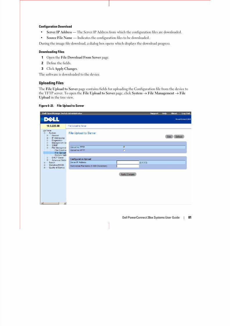
8/21/2019 Powerconnect-2824 User's Guide en-us
http://slidepdf.com/reader/full/powerconnect-2824-users-guide-en-us 81/184
Dell PowerConnect 28xx Systems User Guide 81
Downloading Files
1 Open the File Download From Server page.
2 Define the fields.
3 Click Apply Changes.
The software is downloaded to the device.
Uploading Files
The File Upload to Server page contains fields for uploading the Configuration file from the device tothe TFTP server. To open the File Upload to Server page, click System File Management FileUpload in the tree view.
Figure 6-22. File Upload to Server
The File Upload to Server page contains the following fields:
• Upload via TFTP — Enables initiating upload via the TFTP server.
• Upload via HTTP — Enables initiating upload via the FTP server.
• Server IP Address — The Server IP Address to which the file is uploaded.

8/21/2019 Powerconnect-2824 User's Guide en-us
http://slidepdf.com/reader/full/powerconnect-2824-users-guide-en-us 82/184
82 Dell PowerConnect 28xx Systems User Guide
• Destination File Name (1-64 Characters) — Indicates the file path to which the file is uploaded.
Uploading Files
1 Open the File Upload to Server page.
2 Define the fields.
3 Click Apply Changes.
The software is uploaded to the device.
Restoring Default Settings
The Restore Defaults page allows you to restore the device settings to their factory default values. Toopen the Restore Defaults page, click System File Management Restore Defaults in the tree view.
Figure 6-23. Restore Defaults
The Restore Defaults page contains the following field:
• Restore Configuration Factory Defaults — Sets the device settings to their factory default values.
Restoring Default Settings
1 Open the Restore Defaults page.
2 Check the Restore Configuration Factory Defaults checkbox.
3 Click Apply Changes.
The settings are restored.
Defining DHCP Server SettingsThe DHCP server is used mainly for centralized control over assignment of IP addresses to attached
hosts. A switch can operate as either a DHCP client (obtaining its own IP from a DHCP server) as a DHCP

8/21/2019 Powerconnect-2824 User's Guide en-us
http://slidepdf.com/reader/full/powerconnect-2824-users-guide-en-us 83/184
Dell PowerConnect 28xx Systems User Guide 83
server.
The DHCP server uses a fined pool of IP addresses (user-defined) from which it allocates IP addresses toDHCP clients.
The DHCP server can allocate IP addresses in three configuration modes:
• Static allocation — The network administrator maps the hardware address of a host to an IP address
on the DHCP server.• Permanent allocation — An IP address received through a standard request-reply mechanism is owned
by a client permanently (unless changes in the network environment/connections take place, for anyreason).
• Dynamic allocation — A network device obtains a leased IP address for a specified period of time. TheIP address is revoked at the end of this period and the switch must request another IP address.
This section contains information for configuring a DHCP server on a DHCP-server-enabled switch.
To open the DHCP Server page, click System DHCP Server in the tree view.
Configuring DHCP Properties
The DHCP Server Properties page contains fields for enabling the DHCP server and configuring pingingcapability. The DHCP Server pings a pool address before assigning this address to a requesting client. Ifthe ping is unanswered, the DHCP Server assumes (with a high probability) that the address is not in useand assigns the address to the requesting client. To open the DHCP Server Properties page, click System
DHCP Server DHCP Server Properties in the tree view.
Figure 6-24. DHCP Server Properties
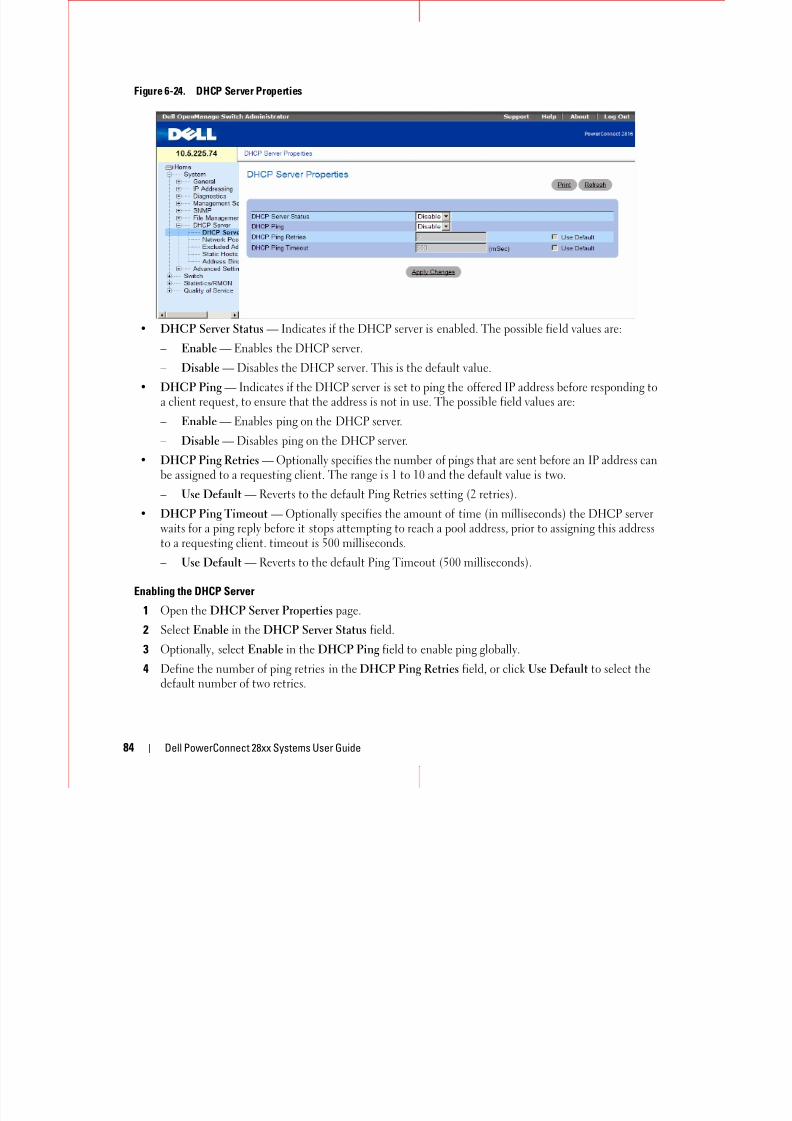
8/21/2019 Powerconnect-2824 User's Guide en-us
http://slidepdf.com/reader/full/powerconnect-2824-users-guide-en-us 84/184
84 Dell PowerConnect 28xx Systems User Guide
• DHCP Server Status — Indicates if the DHCP server is enabled. The possible field values are:
– Enable — Enables the DHCP server.
– Disable — Disables the DHCP server. This is the default value.• DHCP Ping — Indicates if the DHCP server is set to ping the offered IP address before responding to
a client request, to ensure that the address is not in use. The possible field values are:
– Enable — Enables ping on the DHCP server.
– Disable — Disables ping on the DHCP server.
• DHCP Ping Retries — Optionally specifies the number of pings that are sent before an IP address canbe assigned to a requesting client. The range is 1 to 10 and the default value is two.
– Use Default — Reverts to the default Ping Retries setting (2 retries).
• DHCP Ping Timeout — Optionally specifies the amount of time (in milliseconds) the DHCP serverwaits for a ping reply before it stops attempting to reach a pool address, prior to assigning this addressto a requesting client. timeout is 500 milliseconds.
– Use Default — Reverts to the default Ping Timeout (500 milliseconds).
Enabling the DHCP Server
1 Open the DHCP Server Properties page.
2 Select Enable in the DHCP Server Status field.
3 Optionally, select Enable in the DHCP Ping field to enable ping globally.
4 Define the number of ping retries in the DHCP Ping Retries field, or click Use Default to select thedefault number of two retries.
5 Define the amount of time (in milliseconds) the DHCP server waits for a ping reply in the DHCPPing Timeout field, or click Use Default to select the default timeout of 500 milliseconds.
6 Click Apply Changes.
The server is enabled.

8/21/2019 Powerconnect-2824 User's Guide en-us
http://slidepdf.com/reader/full/powerconnect-2824-users-guide-en-us 85/184
Dell PowerConnect 28xx Systems User Guide 85
Defining Network Pool
The Network Pool page displays the DHCP Server's created pool name. The pool name, which istypically assigned to a network segment, consists of an IP address range from which the DHCP Serverallocates IP addresses to DHCP clients. You can define the lease duration of the network pool.
To open the Network Pool page, click System DHCP Server Network Pool in the tree view.
Figure 6-25. Network Pool
• Subnet IP Address — Specifies the IP address of the subnet in which the network pool resides.
• Network Mask — Specifies the pool’s network mask.
• Prefix Length — Specifies the number of bits that comprise the address prefix.• Address Pool Start — Specifies the first IP address in the range of the network pool.
• Address Pool End — Specifies the last IP address in the range of the network pool.
• Lease Duration — Specifies the amount of time a DHCP client can use an IP address from this pool.The total lease duration is 4294967295 seconds, i.e. 49710.2696 days. Thus a lease of 49710 days, 0hours, 0 minutes and 0 seconds is a legal value, while a lease of 49710 days, 23 hours, 59 minutes and59 seconds results in an Out of Range alert.
– Days — Specifies the duration of the lease in number of days. The range is 0 to 49710 days.
– Hours — Specifies the number of hours in the lease. A days value must be supplied before anhours value can be added. The range is 0 to 23 hours.
– Minutes — Specifies the number of minutes in the lease. A days value and an hours value must beadded before a minutes value can be added. The range is 0 to 59 minutes.
8/21/2019 Powerconnect-2824 User's Guide en-us
http://slidepdf.com/reader/full/powerconnect-2824-users-guide-en-us 86/184
86 Dell PowerConnect 28xx Systems User Guide
– Infinite — Specifies that the duration of the lease is unlimited.
• Used Pool’s Addresses — Specifies the number of the pool’s addresses that are currently used.
• Default Router — Specifies the default router for the DHCP client.
• Domain Name Server — Specifies the DNS server available to the DHCP client.
• Domain Name — Specifies the domain name for a DHCP client. The domain name may contain upto 32 characters.
• NetBIOS WINS Server — Specifies the NetBIOS WINS name server available to a DHCP client.
• NetBIOS Node Type — A parameter that informs the workstation how to resolve the NetBIOS name.Valid node types are:
– Broadcast — IP broadcast messages are used to register and resolve NetBIOS names to IPaddresses.
– Peer-to-Peer — Point-to-point communications with a NetBIOS name server are used to registerand resolve computer names to IP addresses.
– Mixed — A combination (mix) of b-node and p-node communications is used to register andresolve NetBIOS names. M-node first uses b-node; then, if necessary, p-node. M-node is typicallynot the best choice for larger networks because its preference for b-node broadcasts increasesnetwork traffic.
– Hybrid — A hybrid combination of b-node and p-node is used. When configured to use h-node, acomputer always tries p-node first and uses b-node only if p-node fails. This is the default.
• SNTP Server — Specifies the time server for the DHCP client.
• Next Server — Specifies the IP address of the next server in the boot process of a DHCP client. If thenext server in the boot process is not configured, the DHCP Server uses inbound interface helperaddresses as boot servers.
• Next Server Name — Specifies the name of the next server in the boot process. The server name maycontain up to 64 characters.
• Image File Name — Specifies the name of the file that is used as a boot image. The file name maycontain up to 128 characters.
Excluding Addresses
By default, the DHCP Server assumes that all pool addresses may be assigned to DHCP clients. The usercan specify IP addresses that must not be used. These addresses are referred to as excluded addresses. Asingle IP address or a range of IP addresses can be excluded.
The Excluded Addresses page lists the excluded addresses. To open the Excluded Addresses page, clickSystem DHCP Server Excluded Addresses in the tree view.
Figure 6-26. Excluded Addresses

8/21/2019 Powerconnect-2824 User's Guide en-us
http://slidepdf.com/reader/full/powerconnect-2824-users-guide-en-us 87/184
Dell PowerConnect 28xx Systems User Guide 87
• Start IP Address — Displays the first IP address in the range of excluded IP addresses.
• End IP Address — Displays the last IP address in the range of excluded IP addresses.
Adding an Excluded Address
1 Open the Excluded Addresses page.
2 Click Add.
The Add Excluded page opens:
Figure 6-27. Add Excluded
3 Define the relevant fields.
4 Click Apply Changes.
The address is excluded, and the device is updated.
Deleting Excluded Addresses
1 Open the Excluded Addresses page.
2 Check the Remove checkbox next to an address.
3 Click Apply Changes. The address is deleted, and the device is updated.
Manually Allocating IP Addresses (Static Hosts)The Static Hosts page is used to manually allocate IP addresses to network hosts. To open the StaticH li k S DHCP S S i H i h i

8/21/2019 Powerconnect-2824 User's Guide en-us
http://slidepdf.com/reader/full/powerconnect-2824-users-guide-en-us 88/184
88 Dell PowerConnect 28xx Systems User Guide
Hosts page, click System DHCP Server Static Hosts in the tree view.
Figure 6-28. Static Hosts
• Host Name — Indicates the host pool name, which can be a string of symbols and an integer (forexample, piy4). The range is up to 32 characters.
• IP Address — Specifies the IP address that was statically assigned to the host.
• Network Mask — Specifies the pool’s network mask.
• Prefix Length — Specifies the number of bits that comprise the address prefix.
• Client Identifier — A unique identification of the client specified in dotted hexadecimal notation,e.g., 01b6.0819.6811.72.
• MAC Address — Specifies the MAC Address of DHCP static host.
• Client Name — Specifies the name of the client, using a standard set of ASCII characters. The clientname must not include the domain name. The range is up to 32 characters.
• Default Router — Specifies the default router for the DHCP static host.
• Domain Name Server — Specifies the DNS server available to the DHCP client.
• Domain Name— Specifies
• NetBIOS WINS Server — Specifies the NetBIOS WINS server available to a Microsoft DHCP statichost.
• NetBIOS Node Type — Informs the workstation how to resolve the NetBIOS name. Valid node types

8/21/2019 Powerconnect-2824 User's Guide en-us
http://slidepdf.com/reader/full/powerconnect-2824-users-guide-en-us 89/184
Dell PowerConnect 28xx Systems User Guide 89
are:
– Broadcast — IP broadcast messages are used to register and resolve NetBIOS names to IPaddresses.
– Peer-to-Peer — Point-to-point communications with a NetBIOS name server are used to registerand resolve computer names to IP addresses.
– Mixed — A combination (mix) of b-node and p-node communications is used to register andresolve NetBIOS names. M-node first uses b-node; then, if necessary, p-node. M-node is typicallynot the best choice for larger networks because its preference for b-node broadcasts increasesnetwork traffic.
– Hybrid — A hybrid combination of b-node and p-node is used. When configured to use h-node, acomputer always tries p-node first and uses b-node only if p-node fails. This is the default.
• SNTP Server — Specifies the time server for the DHCP static host.• Next Server — Specifies the IP address of the next server in the boot process of a DHCP client.
• Next Server Name — Specifies the name of the next server in the boot process. The server name maycontain up to 64 characters.
• File Name — Specifies the name of the file that is used as a boot image. The file name may containup to 128 characters.
Adding a new Static Host1 Open the Static Hosts page.
2 Click Add.
The Add Static Host page opens:
Figure 6-29. Add Static Host
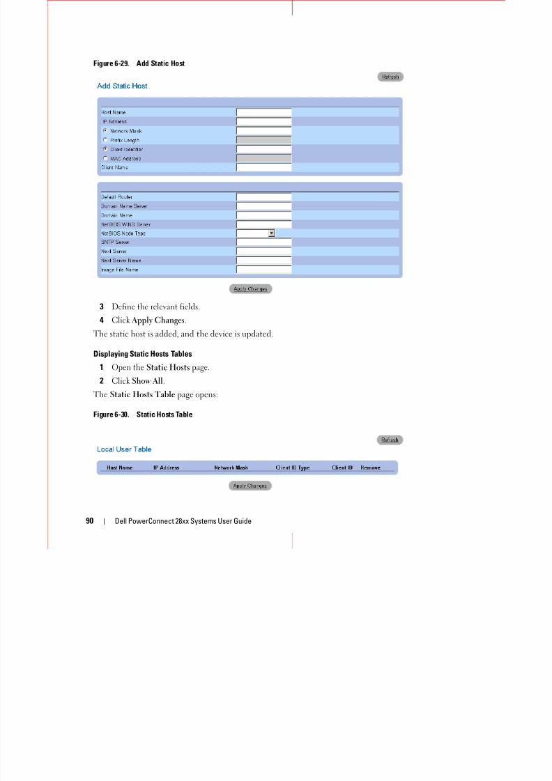
8/21/2019 Powerconnect-2824 User's Guide en-us
http://slidepdf.com/reader/full/powerconnect-2824-users-guide-en-us 90/184
90 Dell PowerConnect 28xx Systems User Guide
3 Define the relevant fields.
4 Click Apply Changes.
The static host is added, and the device is updated.
Displaying Static Hosts Tables
1 Open the Static Hosts page.
2 Click Show All.
The Static Hosts Table page opens:
Figure 6-30. Static Hosts Table
Deleting Static Hosts
1 Open the Static Hosts page.
2 Click Show All.
The Static Hosts Table page opens.
3 Check the Remove checkbox next to a static host.

8/21/2019 Powerconnect-2824 User's Guide en-us
http://slidepdf.com/reader/full/powerconnect-2824-users-guide-en-us 91/184
Dell PowerConnect 28xx Systems User Guide 91
4 Click Apply Changes. The host is deleted, and the device is updated.
Address Binding
The Address Binding page displays a list of the DHCP server’s allocated IP addresses and each IP
address’s client identifier, lease expiration time, and allocation type. Open the Address Binding page,click System DHCP Server Address Binding in the tree view.
Figure 6-31. Address Binding
• IP Address — Displays the IP addresses of the clients whose bindings are displayed.
• Client Identifier — A unique identification of the client specified in dotted hexadecimal notation,e.g., 01b6.0819.6811.72.
• Lease Expiration — Displays the lease expiration date and time of the host’s IP address.
• Type — Displays the manner in which the IP address was assigned to the host:
– Static allocation — The network administrator maps the hardware address of a host to an IPaddress on the DHCP server.
– Permanent allocation — An IP address received through a standard request-reply mechanism isowned by a client permanently
– Dynamic allocation — A network device obtains a leased IP address for a specified period of time.The IP address is revoked at the end of this period and the switch must request another IP address.
Defining Advanced SettingsThe Advanced Settings page contains information for configuring general settings. Use AdvancedSettings to set miscellaneous global attributes for the device. The changes to these attributes are appliedonly after the device is reset. To open the Advanced Settings page, click System Advanced Settings inthe tree view.
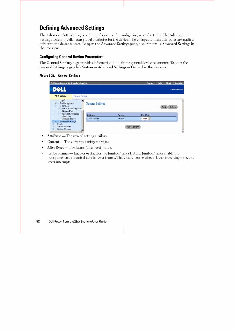
8/21/2019 Powerconnect-2824 User's Guide en-us
http://slidepdf.com/reader/full/powerconnect-2824-users-guide-en-us 92/184
92 Dell PowerConnect 28xx Systems User Guide
Configuring General Device Parameters
The General Settings page provides information for defining general device parameters.To open theGeneral Settings page, click System Advanced Settings General in the tree view.
Figure 6-32. General Settings
• Attribute — The general setting attribute.
• Current — The currently configured value.
• After Reset — The future (after reset) value.
• Jumbo Frames — Enables or disables the Jumbo Frames feature. Jumbo Frames enable thetransportation of identical data in fewer frames. This ensures less overhead, lower processing time, andfewer interrupts.
7Configuring Device SwitchingThis section provides all system operation and general information for configuring network security,
t Add t bl GARP VLAN S i T P t A ti d M lti t S t

8/21/2019 Powerconnect-2824 User's Guide en-us
http://slidepdf.com/reader/full/powerconnect-2824-users-guide-en-us 93/184
Dell PowerConnect 28xx Systems User Guide 93
ports, Address tables, GARP, VLANs, Spanning Tree, Port Aggregation, and Multicast Support.
Configuring Network SecurityThe device enables network security through both Access Control Lists and Locked Ports.
Port Based Authentication (802.1x)
Port based authentication enables authenticating system users on a per-port basis via a externalserver. Only authenticated and approved system users can transmit and receive data. Ports areauthenticated via the RADIUS server using the Extensible Authentication Protocol (EAP). Port
Authentication includes:
• Authenticators — Specifies the port that is authenticated before permitting system access.
• Supplicants — Specifies host connected to the authenticated port requesting to access the systemservices.
• Authentication Server — Specifies the external server, for example, the RADIUS server thatperforms the authentication on behalf of the authenticator, and indicates whether the user isauthorized to access system services.
Port based authentication creates two access states:
• Controlled Access — Permits communication between the user and the system, if the user is
authorized.
• Uncontrolled Access — Permits uncontrolled communication regardless of the port state.
The device currently supports Port Based Authentication via RADIUS servers.
Advanced Port Based Authentication
Advanced Port Based Authentication enables multiple hosts to be attached to a single port. Advanced Port Based Authentication requires only one host to be authorized for all hosts to have
system access. If the port is unauthorized all attached hosts are denied access to the network.
Advanced Port Based Authentication also enables user based authentication. Specific VLANs in thedevice are always available, even if specific ports attached to the VLAN are unauthorized. Forexample, Voice over IP does not require authentication, while data traffic requires authentication.VLANs for which authorization is not required can be defined. Unauthenticated VLANs areavailable to users, even if the ports attached to the VLAN are defined as authorized.
Advanced Port Based Authentication is implemented in the following modes:
• Single Host Mode — Enables only the authorized host for single-session access to the port.
• Multiple Host Mode — Enables multiple hosts to be attached to a single port, for single-session
access. Only one host must be authorized for all hosts to access the network. If the host authenticationfails or an EAPOL-logoff message is received, all attached clients are denied network access.
• Multiple Session Mode — Enables only the authorized host for multiple-session access to the port.

8/21/2019 Powerconnect-2824 User's Guide en-us
http://slidepdf.com/reader/full/powerconnect-2824-users-guide-en-us 94/184
94 Dell PowerConnect 28xx Systems User Guide
p y p p
• Guest VLANs — Provides limited network access to unauthorized ports. If a port is denied networkaccess via port-based authorization, but the Guest VLAN is enabled, the port receives limited networkaccess. For example, a network administrator can use Guest VLANs to deny network access via port-based authentication, but grant Internet access to unauthorized users.
To open the Network Security page select Switch Network Security.
Configuring Port Based Authentication
The Port Based Authentication page contains fields for configuring port based authentication and forenabling Guest VLANs. To open the Port Based Authentication page, click Switch Network Security Port Based Authentication.
Figure 7-1. Port Based Authentication
• Port Based Authentication State — Permits port based authentication on the device. The possiblefield values are:
– Enable — Enables port based authentication on the device.
– Disable — Disables port based authentication on the device.
• Authentication Method — The Authentication method used. The possible field values are:
– None — No authentication method is used to authenticate the port.
– RADIUS — Port authentication is performed using the RADIUS server.
– RADIUS, None — Port authentication is performed first using the RADIUS server. If the port is
not authenticated, then no authentication method is used, and the session is permitted.
• Guest VLAN — Specifies whether the Guest VLAN is enabled on the device. The possible field valuesare:
8/21/2019 Powerconnect-2824 User's Guide en-us
http://slidepdf.com/reader/full/powerconnect-2824-users-guide-en-us 95/184
Dell PowerConnect 28xx Systems User Guide 95
– Enable — Enables using a Guest VLAN for unauthorized ports. If a Guest VLAN is enabled, theunauthorized port automatically joins the VLAN selected in the VLAN List field.
– Disable — Disables . This is the default.
• VLAN List — When Guest VLAN is enabled, this field specifies which VLAN the guest will belong to.• Interface — Contains an interface list.
• User Name — The user name as configured in the RADIUS server.
• Admin Interface Control — Defines the port authorization state. The possible field values are:
• Current Interface Control — The currently configured port authorization state.
• Guest VLAN — Specifies whether the Guest VLAN is enabled on the interface.
• Periodic Reauthentication — Reauthenticates the selected port periodically, when enabled. Thereauthentication period is defined in the Reauthentication Period (300-4294967295) field.
• Reauthentication Period (300-4294967295) — Indicate the time span in which the selected port isreauthenticated. The field value is in seconds. The field default is 3600 seconds.
• Reauthenticate Now — Permits immediate port reauthentication, when selected.
• Authentication Server Timeout (1-65535) — Defines the amount of time that lapses before thedevice resends a request to the authentication server. The field value is in seconds. The field default is
30 seconds.• Resending EAP Identity Request (30-65535) — Defines the amount of time that lapses before EAP
request are resent. The field default is 30 seconds.
• Quiet Period (0-65535) — The number of seconds that the device remains in the quiet state followinga failed authentication exchange. The possible field range is 0-65535. The field default is 60 seconds.
• Supplicant Timeout (1-65535) — The amount of time that lapses before EAP requests are resent tothe user. The field value is in seconds. The field default is 30 seconds.
• Max EAP Requests (1-10) — The total amount of EAP requests sent. If a response is not received afterthe defined period, the authentication process is restarted. The field default is 2 retries.
Displaying the Port Based Authentication Table
1 Display the Port Based Authentication page.
2 Click Show All.
The Port Based Authentication Table opens:
Figure 7-2. Port Based Authentication Table
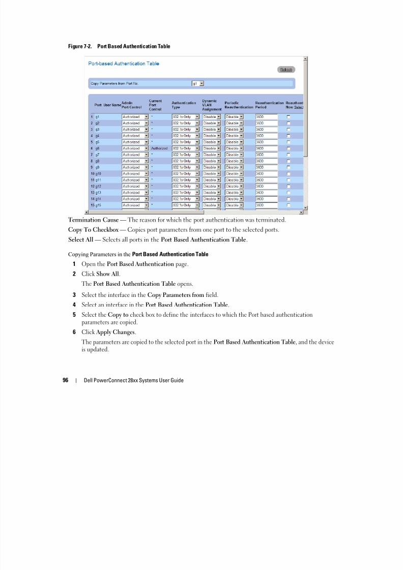
8/21/2019 Powerconnect-2824 User's Guide en-us
http://slidepdf.com/reader/full/powerconnect-2824-users-guide-en-us 96/184
96 Dell PowerConnect 28xx Systems User Guide
Termination Cause — The reason for which the port authentication was terminated.
Copy To Checkbox — Copies port parameters from one port to the selected ports.
Select All — Selects all ports in the Port Based Authentication Table.
Copying Parameters in the Port Based Authentication Table
1 Open the Port Based Authentication page.
2 Click Show All.
The Port Based Authentication Table opens.
3 Select the interface in the Copy Parameters from field.
4 Select an interface in the Port Based Authentication Table.5 Select the Copy to check box to define the interfaces to which the Port based authentication
parameters are copied.
6 Click Apply Changes.
The parameters are copied to the selected port in the Port Based Authentication Table, and the deviceis updated.
Configuring Advanced Port Based Authentication
The Multiple Hosts page provides information for defining advanced port based authentication settingsfor specific ports. To open the Multiple Hosts, click SwitchNetwork Security Multiple Hosts.
Figure 7-3. Multiple Hosts
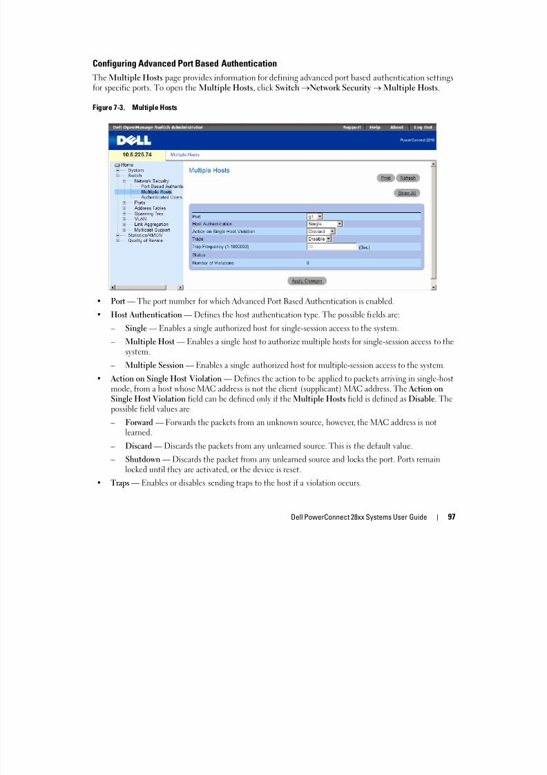
8/21/2019 Powerconnect-2824 User's Guide en-us
http://slidepdf.com/reader/full/powerconnect-2824-users-guide-en-us 97/184
Dell PowerConnect 28xx Systems User Guide 97
• Port — The port number for which Advanced Port Based Authentication is enabled.
• Host Authentication — Defines the host authentication type. The possible fields are:
– Single — Enables a single authorized host for single-session access to the system.
– Multiple Host — Enables a single host to authorize multiple hosts for single-session access to thesystem.
– Multiple Session — Enables a single authorized host for multiple-session access to the system.
• Action on Single Host Violation — Defines the action to be applied to packets arriving in single-hostmode, from a host whose MAC address is not the client (supplicant) MAC address. The Action onSingle Host Violation field can be defined only if the Multiple Hosts field is defined as Disable. Thepossible field values are:
– Forward — Forwards the packets from an unknown source, however, the MAC address is notlearned.
– Discard — Discards the packets from any unlearned source. This is the default value.
– Shutdown — Discards the packet from any unlearned source and locks the port. Ports remainlocked until they are activated, or the device is reset.
• Traps — Enables or disables sending traps to the host if a violation occurs.
• Trap Frequency (1-1000000) (Sec) — Defines the time period by which traps are sent to the host. TheTrap Frequency (1-1000000) field can be defined only if the Multiple Hosts field is defined asDisable. The default is 10 seconds.
• Status — The host status. The possible field values are:– Unauthorized — Clients (supplicants) have full port access.
– Authorized — Cents (supplicants) have limited port access.

8/21/2019 Powerconnect-2824 User's Guide en-us
http://slidepdf.com/reader/full/powerconnect-2824-users-guide-en-us 98/184
98 Dell PowerConnect 28xx Systems User Guide
• Number of Violations — The number of packets that arrived on the interface in single-host mode,from a host whose MAC address is not the client (supplicant) MAC address.
Displaying the Multiple Hosts Table
1 Open the Multiple Hosts page.
2 Click Show All.
The Multiple Hosts Table opens:
Figure 7-4. Multiple Hosts Table
Authenticating Users
The Authenticated Users page displays user port access lists. To open the Authenticated Users page, click Switch Network Security Authenticated Users.
Figure 7-5. Authenticated Users
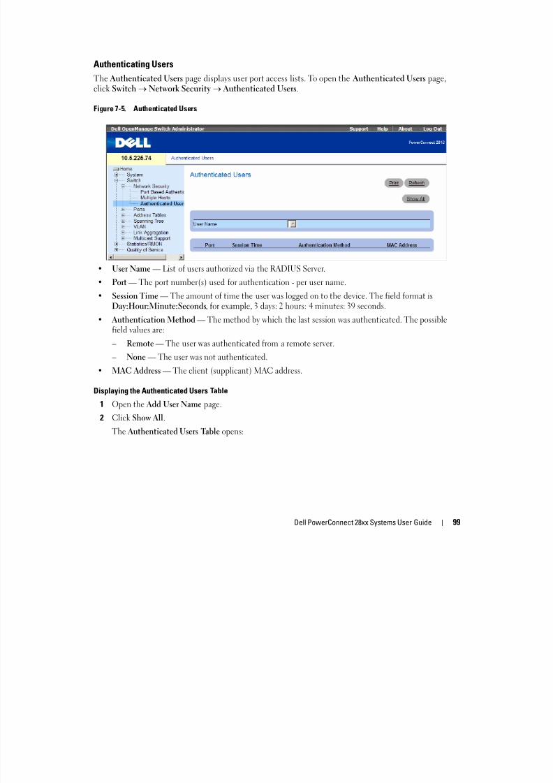
8/21/2019 Powerconnect-2824 User's Guide en-us
http://slidepdf.com/reader/full/powerconnect-2824-users-guide-en-us 99/184
Dell PowerConnect 28xx Systems User Guide 99
• User Name — List of users authorized via the RADIUS Server.
• Port — The port number(s) used for authentication - per user name.
• Session Time — The amount of time the user was logged on to the device. The field format isDay:Hour:Minute:Seconds, for example, 3 days: 2 hours: 4 minutes: 39 seconds.
• Authentication Method — The method by which the last session was authenticated. The possiblefield values are:
– Remote — The user was authenticated from a remote server.
– None — The user was not authenticated.
• MAC Address — The client (supplicant) MAC address.
Displaying the Authenticated Users Table
1 Open the Add User Name page.
2Click Show All.The Authenticated Users Table opens:
Figure 7-6. Authenticated Users Table

8/21/2019 Powerconnect-2824 User's Guide en-us
http://slidepdf.com/reader/full/powerconnect-2824-users-guide-en-us 100/184
100 Dell PowerConnect 28xx Systems User Guide
Configuring PortsThe Ports page contains links to port functionality pages including advanced features, such as GreenEthernet, Storm Control and Port Mirroring. To open the Ports page, click Switch Ports.
Defining Port Parameters
The Port Configuration page contains fields for defining port parameters. To open the PortConfiguration page click Switch Ports Port Configuration in the tree view
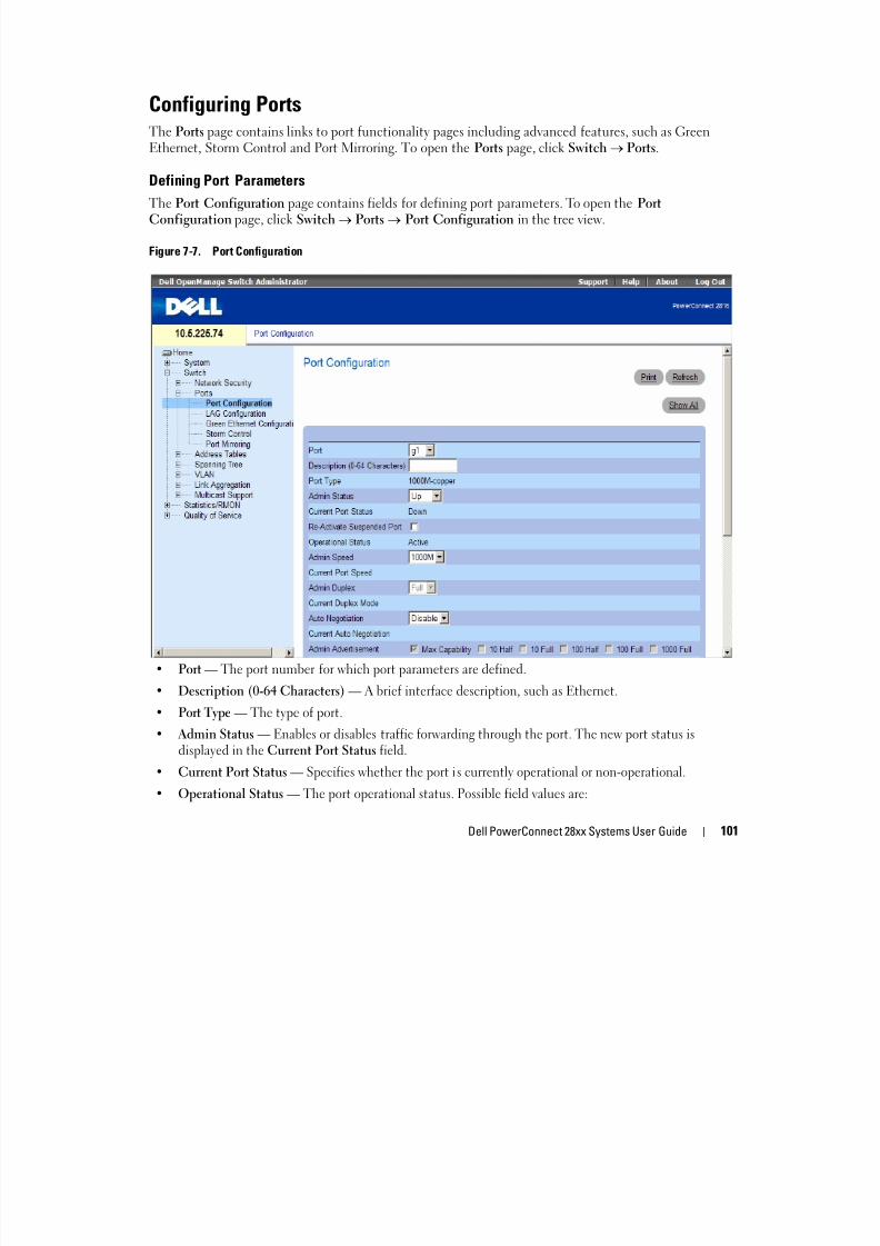
8/21/2019 Powerconnect-2824 User's Guide en-us
http://slidepdf.com/reader/full/powerconnect-2824-users-guide-en-us 101/184
Dell PowerConnect 28xx Systems User Guide 101
Configuration page, click Switch Ports Port Configuration in the tree view.
Figure 7-7. Port Configuration
• Port — The port number for which port parameters are defined.• Description (0-64 Characters) — A brief interface description, such as Ethernet.
• Port Type — The type of port.
• Admin Status — Enables or disables traffic forwarding through the port. The new port status isdisplayed in the Current Port Status field.
• Current Port Status — Specifies whether the port is currently operational or non-operational.
• Operational Status — The port operational status. Possible field values are:
– Active — The port is currently active and is currently receiving and transmitting traffic.
– Disable — The port is currently disabled, and is not currently receiving or transmitting traffic.
• Admin Speed — The configured rate for the port. The port type determines what speed setting
options are available. Admin speed can only be designated when auto negotiation is disabled on theconfigured port.
• Current Port Speed — The actual currently configured port speed (bps).
• Admin Duplex The port duplex mode can be either Full or Half Full indicates that the interface
8/21/2019 Powerconnect-2824 User's Guide en-us
http://slidepdf.com/reader/full/powerconnect-2824-users-guide-en-us 102/184
102 Dell PowerConnect 28xx Systems User Guide
• Admin Duplex — The port duplex mode can be either Full or Half . Full indicates that the interfacesupports transmission between the device and its link partner in both directions simultaneously. Half indicates that the interface supports transmission between the device and the client in only onedirection at a time.
• Current Duplex Mode — The currently configured port duplex mode.
• Auto Negotiation — Enables Auto Negotiation on the port. Auto Negotiation is a protocol betweentwo link partners that enables a port to advertise its transmission rate, duplex mode and flow controlabilities to its partner.
• Current Auto Negotiation — The currently configured Auto Negotiation setting.
• Admin Advertisement — The speed that the port advertises. Options include Maximum Capacity, 1010 MB Full-Duplex, 100 MB Half-Duplex, 100 MB Full-Duplex and 1000 MB Full-Duplex.
• Current Advertisement — The port advertises its speed to its neighbor port to start the negotiationprocess. The possible field values are those specified in the Admin Advertisement field.
• Neighbor Advertisement — Indicates the neighboring port’s advertisement settings. The field valuesare identical to the Admin Advertisement field values.
• Back Pressure — Enables Back Pressure mode on the port. Back Pressure mode is used with HalfDuplex mode to disable ports from receiving messages.
• Current Back Pressure — The currently configured Back Pressure setting.• Flow Control — Enables or disables flow control or enables the auto negotiation of flow control on the
port. Operates when port is in Full duplex mode.
• Current Flow Control — The currently configured Flow Control setting.
• MDI/MDIX — Allows the device to decipher between crossed and uncrossed cables.
Hubs and switches are deliberately wired opposite the way end stations are wired, so that when a hub orswitch is connected to an end station, a straight through Ethernet cable can be used, and the pairs are
match up properly. When two hubs/switches are connected to each other, or two end stations areconnected to each other, a crossover cable is used ensure that the correct pairs are connected. Thepossible field values are:
– Auto — Used to automatically detect the cable type.
– MDI (Media Dependent Interface) — Used for end stations.
– MDIX (Media Dependent Interface with Crossover) — Used for hubs and switches.
• Current MDI/MDIX— The currently configured device MDI/MDIX settings.
• LAG — Specifies if the port is part of a LAG.
Defining Port Parameters
1 Open the Port Configuration page.2 Select a port in the Port Field.
3 Define the remaining fields.
4 Click Apply Changes.

8/21/2019 Powerconnect-2824 User's Guide en-us
http://slidepdf.com/reader/full/powerconnect-2824-users-guide-en-us 103/184
Dell PowerConnect 28xx Systems User Guide 103
4 Click Apply Changes.
The port parameters are saved to the device.
Modifying Port Parameters
1 Open the Port Configuration page.
2 Select a port in the Port Field.
3 Modify the remaining fields.
4 Click Apply Changes.
The port parameters are saved to the device.
Displaying the Port Configuration Table:1 Open the Port Configuration page.
2 Click Show All.
The Ports Configuration Table opens:
Figure 7-8. Ports Configuration Table
Aggregating Ports
Load Balancing enables the even distribution of data and/or processing packets across available networkresources. For example, load balancing may distribute the incoming packets evenly to all servers, orredirect the packets to the next available server. Load Balancing is configured on the "LAGConfiguration" on page 104 page.
LAGs can be configured according to the following load balancing types: Layer 2, Layer 2 and Layer 3 orLayer 3.
The LAG Configuration page contains fields for configuring parameters for configured LAGs. The
device supports up to eight LAGs, and each LAG can have up to eight members.For information about
To open the LAG Configuration page, click Switch Ports LAG Configuration in the tree view.
If port configuration is modified while the port is a LAG member, the configuration change is only
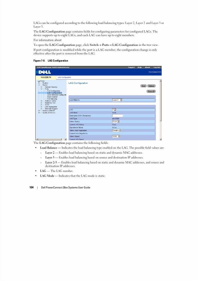
8/21/2019 Powerconnect-2824 User's Guide en-us
http://slidepdf.com/reader/full/powerconnect-2824-users-guide-en-us 104/184
104 Dell PowerConnect 28xx Systems User Guide
p g p , g g yeffective after the port is removed from the LAG.
Figure 7-9. LAG Configuration
The LAG Configuration page contains the following fields:
• Load Balance — Indicates the load balancing type enabled on the LAG. The possible field values are:
– Layer 2 — Enables load balancing based on static and dynamic MAC addresses.
– Layer 3 — Enables load balancing based on source and destination IP addresses.
– Layer 2-3 — Enables load balancing based on static and dynamic MAC addresses, and source anddestination IP addresses.
• LAG — The LAG number.
• LAG Mode — Indicates that the LAG mode is static.
• Description (0-64 Characters) — Provides a user-defined description of the configured LAG.
• LAG Type — The port types that comprise the LAG.
• Admin Status — Enables or disables traffic forwarding through the selected LAG.
• Current LAG Status — Indicates if the LAG is currently operating.
• Operational Status — Operational status of the LAG.
• Admin Auto Negotiation — Enables or disables Auto Negotiation on the LAG. Auto-negotiation is aprotocol between two link partners that enables a LAG to advertise its transmission rate and flow

8/21/2019 Powerconnect-2824 User's Guide en-us
http://slidepdf.com/reader/full/powerconnect-2824-users-guide-en-us 105/184
Dell PowerConnect 28xx Systems User Guide 105
protocol between two link partners that enables a LAG to advertise its transmission rate and flowcontrol (the flow control default is ) abilities to its partner.
• Current Auto Negotiation — The currently configured Auto Negotiation setting.
• Admin Speed — The speed at which the LAG is operating.• Current LAG Speed — The currently configured speed at which the LAG is operating.
• Admin Advertisement — The speed that the LAG advertises. Options include Maximum Capacity,10 MB Full-Duplex, 100 MB Full-Duplex and 1000 MB Full-Duplex.
• Current Advertisement — The port advertises its speed to its neighbor port to start the negotiationprocess. The possible field values are those specified in the Admin Advertisement field.
• Neighbor Advertisement — Indicates the neighboring port’s advertisement settings. The field values
are identical to the Admin Advertisement field values.
• Admin Flow Control — Enables/disables flow control, or enables the auto negotiation of flow controlon the LAG.
• Current Flow Control — The .
Defining LAG Parameters
1 Open the LAG Configuration page.
2 Select a LAG in the LAG field.
3 Define the fields.
4 Click Apply Changes.
The LAG parameters are saved to the device.
Modifying LAG Parameters
1 Open the LAG Configuration page.2 Select a LAG in the LAG field.
3 Modify the fields.
4 Click Apply Changes.
The LAG parameters are saved to the device.
Displaying the LAG Configuration Table:
1 Open the LAG Configuration page.
2 Click Show All.
The LAG Configuration Table opens:
Figure 7-10. LAG Configuration Table
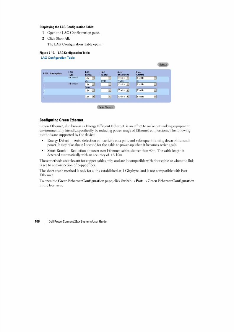
8/21/2019 Powerconnect-2824 User's Guide en-us
http://slidepdf.com/reader/full/powerconnect-2824-users-guide-en-us 106/184
106 Dell PowerConnect 28xx Systems User Guide
Configuring Green Ethernet
Green Ethernet, also known as Energy Efficient Ethernet, is an effort to make networking equipmentenvironmentally friendly, specifically by reducing power usage of Ethernet connections. The followingmethods are supported by the device:
• Energy-Detect — Auto-detection of inactivity on a port, and subsequent turning down of transmit
power. It may take about 1 second for the cable to power-up when it becomes active again.• Short-Reach — Reduction of power over Ethernet cables shorter than 40m. The cable length is
detected automatically with an accuracy of +/- 10m.
These methods are relevant for copper cables only, and are incompatible with fiber cable or when the linkis set to auto-selection of copper/fiber.
The short-reach method is only for a link established at 1 Gigabyte, and is not compatible with FastEthernet.
To open the Green Ethernet Configuration page, click Switch Ports Green Ethernet Configurationin the tree view.
Figure 7-11. Green Ethernet Configuration

8/21/2019 Powerconnect-2824 User's Guide en-us
http://slidepdf.com/reader/full/powerconnect-2824-users-guide-en-us 107/184
Dell PowerConnect 28xx Systems User Guide 107
• Cumulative Energy Saved — The total amount of energy saved since the last reset. This amount is
equal to the saved power multiplied by the time period in hours.– Reset — Click to set the Cumulative Power Saved counter back to 0.
• — Indicates whether the Energy-Detect saving mode is on or off for the device ports.
• Link Short-Reach Energy Mode — Indicates whether the Short-Reach energy saving mode is on or offfor the device ports.
• Current Power Consumption — The power currently consumed by all ports (including both thosewith links up and links down).
• Power Saving — The percentage of power saved. For example, a Power Saving value of % indicates thatjust % of the power that would normally be used (without Green Ethernet) is currently being used.
The Green Ethernet Ports Table includes the following port energy saving information:
• Port — Indicates the port.
• Energy-Detect — The status of the Energy-Detect mode on the link:
– Admin — Whether the Energy-Detect has been enabled for the port.
– Oper — Whether Energy-Detect is currently in force for the port.
– Reason — If Admin indicates that Energy-Detect is enabled and Oper indicates it is not in force,this column gives the reason. Reasons may include that the Link Type is not supported, or that the
Port Link is up.• Short-Reach — The status of the Short-Reach mode on the link:
– Admin — Whether the Short-Reach has been enabled for the port.
– Oper — Whether Short-Reach is currently in force for the port.
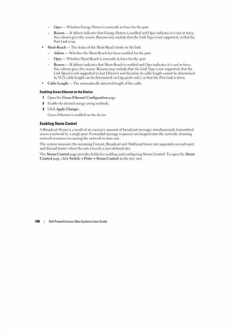
8/21/2019 Powerconnect-2824 User's Guide en-us
http://slidepdf.com/reader/full/powerconnect-2824-users-guide-en-us 108/184
108 Dell PowerConnect 28xx Systems User Guide
– Reason — If Admin indicates that Short-Reach is enabled and Oper indicates it is not in force,this column gives the reason. Reasons may include that the Link Type is not supported, that theLink Speed is not supported (is fast Ethernet and therefore its cable length cannot be determined
by VCT; cable length can be determined on Giga ports only), or that the Port Link is down.• Cable Length — The automatically-detected length of the cable.
Enabling Green Ethernet on the Device
1 Open the Green Ethernet Configuration page.
2 Enable the desired energy saving methods.
3 Click Apply Changes.
Green Ethernet is enabled on the device.
Enabling Storm Control
A Broadcast Storm is a result of an excessive amount of broadcast messages simultaneously transmittedacross a network by a single port. Forwarded message responses are heaped onto the network, strainingnetwork resources or causing the network to time out.
The system measures the incoming Unicast, Broadcast and Multicast frame rate separately on each port,and discard frames when the rate exceeds a user-defined rate.
The Storm Control page provides fields for enabling and configuring Storm Control. To open the StormControl page, click Switch Ports Storm Control in the tree view.
Figure 7-12. Storm Control
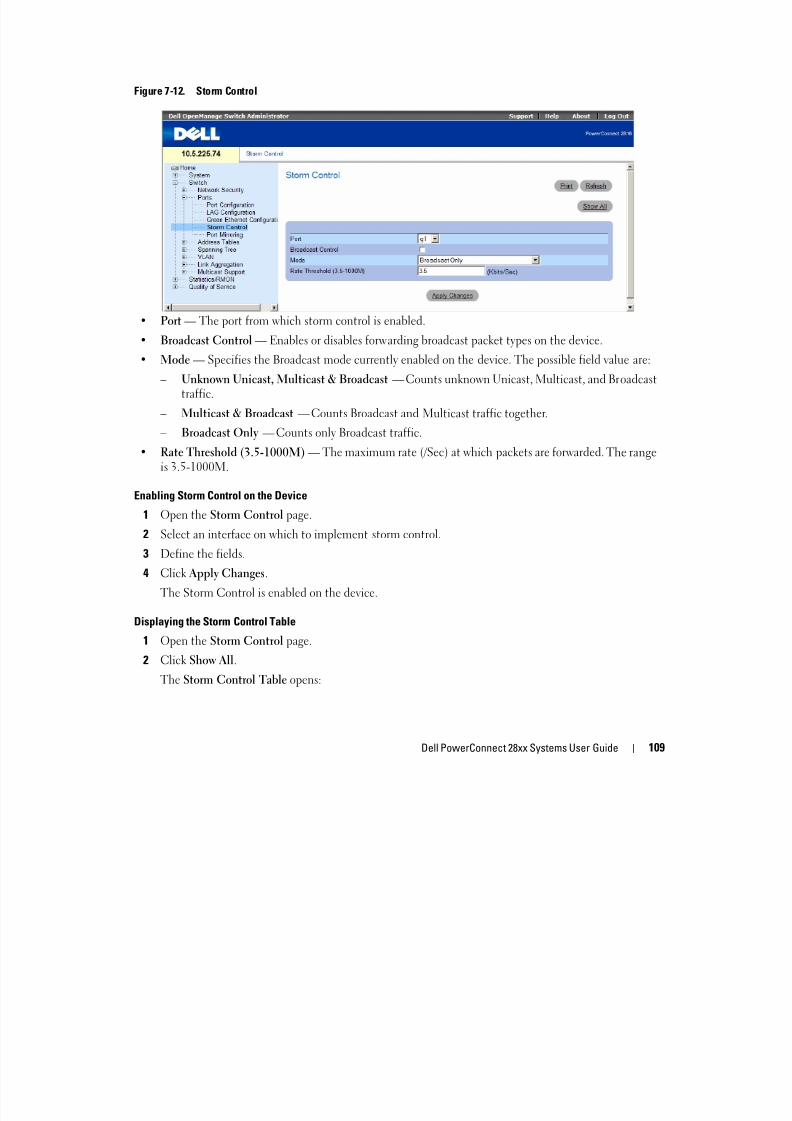
8/21/2019 Powerconnect-2824 User's Guide en-us
http://slidepdf.com/reader/full/powerconnect-2824-users-guide-en-us 109/184
Dell PowerConnect 28xx Systems User Guide 109
• Port — The port from which storm control is enabled.
• Broadcast Control — Enables or disables forwarding broadcast packet types on the device.
• Mode — Specifies the Broadcast mode currently enabled on the device. The possible field value are:
– Unknown Unicast, Multicast & Broadcast — Counts unknown Unicast, Multicast, and Broadcasttraffic.
– Multicast & Broadcast — Counts Broadcast and Multicast traffic together.
– Broadcast Only — Counts only Broadcast traffic.
• Rate Threshold (3.5-1000M) — The maximum rate (/Sec) at which packets are forwarded. The rangeis 3.5-1000M.
Enabling Storm Control on the Device
1 Open the Storm Control page.
2 Select an interface on which to implement storm control.
3 Define the fields.
4 Click Apply Changes.
The Storm Control is enabled on the device.
Displaying the Storm Control Table
1 Open the Storm Control page.
2 Click Show All.
The Storm Control Table opens:
Figure 7-13. Storm Control Table

8/21/2019 Powerconnect-2824 User's Guide en-us
http://slidepdf.com/reader/full/powerconnect-2824-users-guide-en-us 110/184
110 Dell PowerConnect 28xx Systems User Guide
Defining Port Mirroring Sessions
Port mirroring monitors and mirrors network traffic by forwarding copies of incoming and outgoingpackets from one port to a monitoring port.
Port mirroring is configured by selecting a specific port to copy all packets, and different ports fromwhich the packets copied. Before configuring Port Mirroring, note the following:
When a port is set to be a target port for a port-mirroring session, all normal operations on it aresuspended. This includes Spanning Tree.
Before configuring Port Mirroring, note the following:
• Monitored port cannot operate faster than the monitoring port.
• All the RX/TX packets should be monitored to the same port.
The following restrictions apply to ports configured to be destination ports:
• Destination ports cannot be configured as a source port.
• Destination ports cannot be a LAG member.
• IP interfaces are not configured on the port.
• GVRP is not enabled on the port.
• The port is not a VLAN member.
• Only one destination port can be defined.
The following restrictions apply to ports configured to be source ports:
• Source ports cannot be a LAG member.
• Source ports cannot be configured as a destination port.
• All packets are transmitted tagged from the destination port.
• Monitored all RX/TX packets to the same port.
To open the Port Mirroring page, click Switch Ports Port Mirroring in the tree view.
Figure 7 14 Port Mirroring
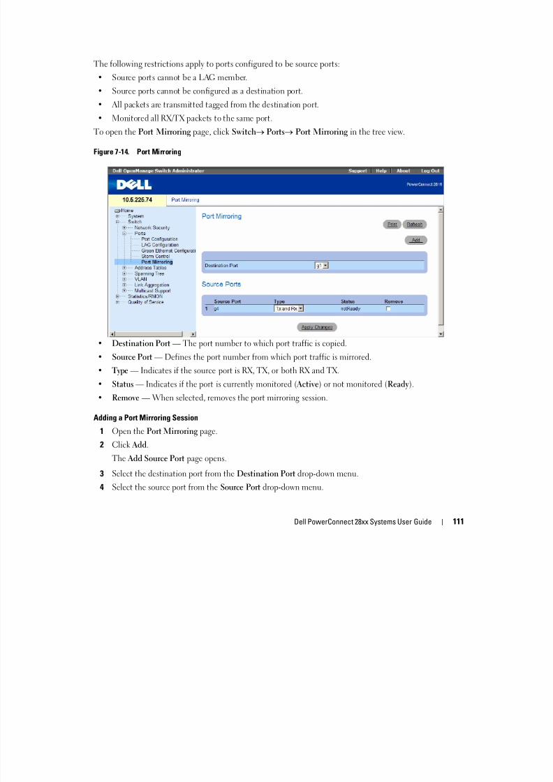
8/21/2019 Powerconnect-2824 User's Guide en-us
http://slidepdf.com/reader/full/powerconnect-2824-users-guide-en-us 111/184
Dell PowerConnect 28xx Systems User Guide 111
Figure 7-14. Port Mirroring
• Destination Port — The port number to which port traffic is copied.• Source Port — Defines the port number from which port traffic is mirrored.
• Type — Indicates if the source port is RX, TX, or both RX and TX.
• Status — Indicates if the port is currently monitored (Active) or not monitored (Ready).
• Remove — When selected, removes the port mirroring session.
Adding a Port Mirroring Session
1 Open the Port Mirroring page.
2 Click Add.
The Add Source Port page opens.
3 Select the destination port from the Destination Port drop-down menu.
4 Select the source port from the Source Port drop-down menu.
5 Define the Type field.
6 Click Apply Changes.
The new source port is defined, and the device is updated.
Deleting a Copy Port from a Port Mirroring Session
1 Open the Port Mirroring page.
2 Select the Remove check box.
3 Click Apply Changes
8/21/2019 Powerconnect-2824 User's Guide en-us
http://slidepdf.com/reader/full/powerconnect-2824-users-guide-en-us 112/184
112 Dell PowerConnect 28xx Systems User Guide
3 Click Apply Changes.
The selected port mirroring session is deleted, and the device is updated.
Configuring Address TablesMAC addresses are stored in the Dynamic Address database. A packet addressed to a destination storedin the database is forwarded immediately to the port. The Dynamic Address Table can be sorted byinterface, VLAN, and interface type. MAC addresses are dynamically learned as packets from sourcesarrive at the device. Addresses are associated with ports by learning the ports from the frame’s sourceaddress. Frames addressed to a destination MAC address that is not associated with any port are floodedto all ports of the relevant VLAN. In order to prevent the bridging table from overflowing, dynamic MACaddresses, from which no traffic is seen for a certain period, are erased. To open the Address Tables page,click Switch Address Table in the tree view.
Viewing Dynamic Addresses
The Dynamic Address Table contains fields for querying information in the dynamic address table,including the interface type, MAC addresses, VLAN, and table sorting. Packets forwarded to an addressstored in the address table are forwarded directly to those ports.
The Dynamic Address Table also contains information about the aging time before a dynamic MACaddress is erased, and includes parameters for querying and viewing the Dynamic Address list. The Current Address Table contains dynamic address parameters by which packets are directly forwarded tothe ports.
To open the Dynamic Address Table, click Switch Address Table Dynamic Addresses Table in thetree view.
Figure 7-15. Dynamic Address Table

8/21/2019 Powerconnect-2824 User's Guide en-us
http://slidepdf.com/reader/full/powerconnect-2824-users-guide-en-us 113/184
Dell PowerConnect 28xx Systems User Guide 113
• Address Aging (10-630) — Specifies the amount of time the MAC Address remains in the DynamicAddress Table before it is timed out if no traffic from the source is detected. The default value is300 seconds.
• Interface — Specifies the interface for which the table is queried. There are two interface types fromwhich to select.
– Port — Specifies the port numbers for which the table is queried.
– LAG — Specifies the LAG for which the table is queried.
• MAC Address — Specifies the MAC address for which the table is queried.
• VLAN ID — Specifies the VLAN ID for which the table is queried.
• Address Table Sort Key — Specifies the means by which the Dynamic Address Table is sorted.
Redefining the Aging Time
1 Open the Dynamic Address Table.
2 Define the Aging Time field.
3 Click Apply Changes.
The aging time is modified, and the device is updated.
Querying the Dynamic Address Table
1 Open the Dynamic Address Table.
2 Define the parameter by which to query the Dynamic Address Table.
Entries can be queried by Port, MAC Address, or VLAN ID.
3 Click Query.
The Dynamic Address Table is queried.
Sorting the Dynamic Address Table

8/21/2019 Powerconnect-2824 User's Guide en-us
http://slidepdf.com/reader/full/powerconnect-2824-users-guide-en-us 114/184
114 Dell PowerConnect 28xx Systems User Guide
Sorting the Dynamic Address Table
1 Open the Dynamic Address Table.
2 From the Address Table Sort Key drop-down menu, select whether to sort addresses by address, VLANID, or interface.
3 Click Query.
The Dynamic Address Table is sorted.
Configuring the Spanning Tree ProtocolSpanning Tree Protocol (STP) provides tree topography for any arrangement of bridges. STP alsoprovides one path between end stations on a network, eliminating loops.
Loops occur when alternate paths exist between hosts. Loops in an extended network can cause bridgesto forward traffic indefinitely, resulting in increased traffic and reducing network efficiency.
The devices support the following Spanning Tree protocols:
• Classic STP — Provides a single path between end stations, avoiding and eliminating loops. For moreinformation on configuring Classic STP, see "Defining STP Global Settings" on page 114.
• Rapid STP — Detects and uses of network topologies that provide faster spanning tree convergence,without creating forwarding loops. For more information on configuring Rapid STP, see "ConfiguringRapid Spanning Tree" on page 122.
To open the Spanning Tree pages, click Switch Spanning Tree in the tree view.
Defining STP Global Settings
The STP Global Settings page contains parameters for enabling and configuring STP operation on the
device. To open the STP Global Settings page, click Switch
Spanning Tree
Global Settings in thetree view.
Figure 7-16. STP Global Settings

8/21/2019 Powerconnect-2824 User's Guide en-us
http://slidepdf.com/reader/full/powerconnect-2824-users-guide-en-us 115/184
Dell PowerConnect 28xx Systems User Guide 115
• Spanning Tree State — Enables or disables Spanning Tree on the device. The possible field values are:
– Enable — Enables Spanning Tree
– Disable — Disables Spanning Tree
• STP Operation Mode — The STP mode by which STP is enabled on the device. The possible field
values are:
– Classic STP — Enables Classic STP on the device. This is the default value.
– Rapid STP — Enables Rapid STP on the device.
• BPDU Handling — Determines how BPDU packets are managed when STP is disabled on the port/device. BPDUs are used to transmit spanning tree information. The possible field values are:
– Filtering — Filters BPDU packets when spanning tree is disabled on an interface.
– Flooding — Floods BPDU packets when spanning tree is disabled on an interface. This is thedefault value.
• Port Cost Default Values — Determines the Spanning Tree default path cost method. The possiblefield values are:
– Short — Specifies 1 through 65535 range for port path costs. This is the default value.
– Long — Specifies 1 through 200000000 range for port path costs.
• Priority (0-61440 in steps of 4096) — Specifies the bridge priority value. When switches or bridges arerunning STP, each is assigned a priority. After exchanging BPDUs, the switch with the lowest priorityvalue becomes the Root Bridge. The default value is 32768. The bridge priority value is provided inincrements of 4096 (4K increments). For example, 0, 4096, 8192, etc.
• Hello Time (1-10) — Specifies the device Hello Time. The Hello Time indicates the amount of timein seconds a root bridge waits between configuration messages. The default is 2 seconds.
• Max Age (6-40) — Specifies the device Maximum Age Time. The Maximum Age Time indicates theamount of time in seconds a bridge waits before sending configuration messages. The default max ageis 20 seconds.

8/21/2019 Powerconnect-2824 User's Guide en-us
http://slidepdf.com/reader/full/powerconnect-2824-users-guide-en-us 116/184
116 Dell PowerConnect 28xx Systems User Guide
• Forward Delay (4-30) — Specifies the device forward delay time. The Forward Delay Time indicatesthe amount of time in seconds a bridge remains in a listening and learning state before forwarding
packets. The default is 15 seconds.
• Bridge ID — Identifies the Bridge priority and MAC address.
• Root Bridge ID — Identifies the Root Bridge priority and MAC address.
• Root Port — The port number that offers the lowest cost path from this bridge to the Root Bridge. It issignificant when the Bridge is not the Root. The default is zero.
• Root Path Cost — The cost of the path from this bridge to the root.
• Topology Changes Counts — Specifies the total amount of STP state changes that have occurredsince the last reboot.
• Last Topology Change — The amount of time that has elapsed since the bridge was initialized orreset, and the last topographic change occurred. The time is displayed in a day hour minute secondformat, for example, 0 day 1 hour 34 minutes and 38 seconds.
Defining STP Global Parameters
1 Open the STP Global Settings page.2 Select the port that needs to be enabled from the Select a Port drop-down menu.
3 Select Enable in the Spanning Tree State field.
4 Select the STP mode in the STP Operation Mode field, and define the bridge settings.
5 Click Apply Changes.
STP is enabled on the device.
Modifying STP Global Parameters
1 Open the STP Global Settings page.
2 Define the fields in the dialog.
3 Click Apply Changes.
The STP parameters are modified, and the device is updated.
Defining STP Port Settings
The STP Port Settings page contains fields for assigning STP properties to individual ports. To open theSTP Port Settings page, click Switch Spanning Tree Port Settings in the tree view.
Figure 7-17. STP Port Settings

8/21/2019 Powerconnect-2824 User's Guide en-us
http://slidepdf.com/reader/full/powerconnect-2824-users-guide-en-us 117/184
Dell PowerConnect 28xx Systems User Guide 117
• Select a Port — Port on which STP is enabled.
• STP — Enables or disables STP on the port.
• Fast Link — When selected, enables Fast Link mode for the port. If Fast Link mode is enabled for aport, the Port State is automatically placed in the Forwarding state when the port link is up. Fast Linkmode optimizes the time it takes for the STP protocol to converge. STP convergence can take 30-60seconds in large networks.
• Root Guard — When checked, prevents devices outside the network core from being assigned the
spanning tree root.
• Port State — The current port STP state. If enabled, the port state determines what forwarding actionis taken on traffic. Possible port states are:
– Disabled — The port link is currently down.
– Blocking — The port is currently blocked and cannot be used to forward traffic or learn MACaddresses. Blocking is displayed when Classic STP is enabled.
– Listening — The port is currently in the listening mode. The port cannot forward traffic nor can itlearn MAC addresses.
– Learning — The port is currently in the learning mode. The port cannot forward traffic however itcan learn new MAC addresses.

8/21/2019 Powerconnect-2824 User's Guide en-us
http://slidepdf.com/reader/full/powerconnect-2824-users-guide-en-us 118/184
118 Dell PowerConnect 28xx Systems User Guide
can learn new MAC addresses.
– Forwarding — The port is currently in the forwarding mode. The port can forward traffic and learn
new MAC addresses.• Role — Displays the port role assigned by the STP algorithm to provide to STP paths. The possible
field values are:
– Root — Provides the lowest cost path to forward packets to the root switch.
– Designated — Indicates the port or LAG through which the designated switch is attached to theLAN.
– Alternate — Provides an alternate path to the root switch from the root interface.
– Backup — Provides a backup path to the designated port path toward the Spanning Tree leaves.Backup ports occur only when two ports are connected in a loop by a point-to-point link, or when aLAN has two or more connections connected to a shared segment.
– Disabled — The port is not participating in the Spanning Tree.
• Speed — Speed at which the port is operating.
• Path Cost (1-200000000) — The port contribution to the root path cost. The path cost is adjusted to
a higher or lower value, and is used to forward traffic when a path being rerouted.• Default Path Cost — The default path cost of the port is automatically set by the port speed and the
default path cost method.
The default values for long path costs are:
– Ethernet - 2000000
– Fast Ethernet - 200000
– Gigabit Ethernet - 20000
The default values for short path costs (short path costs are the default) are:
– Ethernet - 100
– Fast Ethernet - 19
– Gigabit Ethernet - 4
• Priority — The priority value of the port. The priority value influences the port choice when a bridgehas two ports connected in a loop. The priority value is between 0-240. The priority value is provided inincrements of 16.
• Designated Bridge ID — The bridge priority and the MAC Address of the designated bridge.
• Designated Port ID — The selected port’s priority and interface.
• Designated Cost — The cost of the port participating in the STP topology. Ports with a lower cost areless likely to be blocked if STP detects loops.
• Forward Transitions — The number of times the port has changed from the Blocking state to theForwarding state.

8/21/2019 Powerconnect-2824 User's Guide en-us
http://slidepdf.com/reader/full/powerconnect-2824-users-guide-en-us 119/184
Dell PowerConnect 28xx Systems User Guide 119
g
• LAG — The LAG to which the port is attached.
Enabling STP on a Port
1 Open the STP Port Settings page.
2 Select Enabled in the STP Port Status field.
3 Define the Fast Link , Path Cost, and the Priority fields.
4 Click Apply Changes.
STP is enabled on the port.
Modifying STP Port Properties
1 Open the STP Port Settings page.
2 Modify the Priority, Fast Link, Path Cost, and the Fast Link fields.
3 Click Apply Changes.
The STP port parameters are modified, and the device is updated.
Displaying the STP Port Table
1 Open the STP Port Settings page.
2 Click Show All.
The STP Port Table opens.
Defining STP LAG Settings
The STP LAG Settings page contains fields for assigning STP aggregating port parameters. To open theSTP LAG Settings page, click Switch Spanning Tree LAG Settings in the tree view.
Figure 7-18. STP LAG Settings

8/21/2019 Powerconnect-2824 User's Guide en-us
http://slidepdf.com/reader/full/powerconnect-2824-users-guide-en-us 120/184
120 Dell PowerConnect 28xx Systems User Guide
• Select a LAG — The user-defined LAG. For more information, see "Defining LAG Membership" onpage 132.
• STP — Enables or disables STP on the LAG.
• Fast Link — Enables Fast Link mode for the LAG. If Fast Link mode is enabled for a LAG, the LAGState is automatically placed in the Forwarding state when the LAG is up. Fast Link mode optimizesthe time it takes for the STP protocol to converge. STP convergence can take 30-60 seconds in large
networks.• Root Guard — When checked, prevents devices outside the network core from being assigned the
spanning tree root.
• LAG State — Current STP state of a LAG. If enabled, the LAG state determines what forwardingaction is taken on traffic. If the bridge discovers a malfunctioning LAG, the LAG is placed in theBroken state. Possible LAG states are:
– Disabled — The LAG link is currently down.
– Blocking — The LAG is blocked and cannot be used to forward traffic or learn MAC addresses.
– Listening — The LAG is in the listening mode and cannot forward traffic or learn MAC addresses.
– Learning — The LAG is in the learning mode and cannot forward traffic, but it can learn newMAC addresses.
– Forwarding — The LAG is currently in the forwarding mode, and it can forward traffic and learn
8/21/2019 Powerconnect-2824 User's Guide en-us
http://slidepdf.com/reader/full/powerconnect-2824-users-guide-en-us 121/184
Dell PowerConnect 28xx Systems User Guide 121
g y g ,new MAC addresses.
– Broken — The LAG is currently malfunctioning and cannot be used for forwarding traffic.
• Role — Displays the port role assigned by the STP algorithm to provide to STP paths. The possiblefield values are:
– Root — Provides the lowest cost path to forward packets to the root switch.
– Designated — Indicates the port or LAG through which the designated switch is attached to theLAN.
– Alternate — Provides an alternate path to the root switch from the root interface.– Backup — Provides a backup path to the designated port path toward the Spanning Tree leaves.
Backup ports occur only when two ports are connected in a loop by a point-to-point link, or when aLAN has two or more connections connected to a shared segment.
– Disabled — The port is not participating in the Spanning Tree.
• Path Cost (1-200000000) — Amount the LAG contributes to the root path cost. The path cost isadjusted to a higher or lower value, and is used to forward traffic when a path being rerouted. The path
cost has a value of 1 to 200000000. If the path cost method is short, the LAG cost default value is 4. Ifthe path cost method is long, the LAG cost default value is 20000.
• Default Path Cost — When selected, the LAG path cost returns to its default value.
• Priority — The priority value of the LAG. The priority value influences the LAG choice when a bridgehas two looped ports. The priority value is between 0-240, in increments of 16.
• Designated Bridge ID — The bridge priority and the MAC Address of the designated bridge.
• Designated Port ID — The port priority and interface number of the designated port.
• Designated Cost — The cost of the designated bridge.
• Forward Transitions — The number of times the LAG State has changed from the Blocking state to aForwarding state.
Modifying the LAG STP Parameters
1 Open the STP LAG Settings page.
2 Select a LAG from the Select a LAG drop-down menu.
3 Modify the fields as desired.4 Click Apply Changes.
The STP LAG parameters are modified, and the device is updated.
Configuring Rapid Spanning Tree
While Classic Spanning Tree guarantees preventing L2 forwarding loops in a general network topology

8/21/2019 Powerconnect-2824 User's Guide en-us
http://slidepdf.com/reader/full/powerconnect-2824-users-guide-en-us 122/184
122 Dell PowerConnect 28xx Systems User Guide
While Classic Spanning Tree guarantees preventing L2 forwarding loops in a general network topology,convergence can take up to 30-60 seconds. The convergence time is considered too long for many
applications. When network topology allows, faster convergence may be possible. The Rapid SpanningTree Protocol (RSTP) detects and uses of network topologies that provide faster convergence of thespanning tree, without creating forwarding loops.
RSTP has the following port states:
• Disabled
• Learning
• Discarding• Forwarding
Rapid Spanning Tree is enabled on the STP Global Settings page. To open the Rapid Spanning Tree(RSTP) page, click Switch Spanning Tree Rapid Spanning Tree in the tree view.
Figure 7-19. Rapid Spanning Tree (RSTP)

8/21/2019 Powerconnect-2824 User's Guide en-us
http://slidepdf.com/reader/full/powerconnect-2824-users-guide-en-us 123/184
Dell PowerConnect 28xx Systems User Guide 123
• Interface — Port or LAG on which Rapid STP is enabled.
• Role — The port role assigned by the STP algorithm in order to provide to STP paths. The possiblefield values are:
– Root — Provides the lowest cost path to forward packets to root device.
– Designated — The port or LAG via which the designated device is attached to the LAN.
– Alternate — Provides an alternate path to the root device from the root interface.
– Backup — Provides a backup path to the designated port path toward the Spanning Tree leaves.Backup ports occur only when two ports are connected in a loop. Backup ports also occur when aLAN has two or more connections connected to a shared segment.
– Disabled — The port is not participating in the Spanning Tree (the port’s link is down).
• Mode — Displays the STP mode by which STP is enabled on the device. The possible field values are:
– Classic STP — Enables Classic STP on the device. This is the default value.
– Rapid STP — Enables Rapid STP on the device.• Fast Link Operational Status — Indicates if Fast Link is enabled or disabled for the port or LAG. If
Fast Link is enabled for a port, the port is automatically placed in the forwarding state.
Enabling RSTP
1 Open the Rapid Spanning Tree (RSTP) page.
2 Define the Point-to-Point Admin, Point-to-Point Oper, and the Activate Protocol Migration fields.
3 Click Apply Changes.
Rapid STP is enabled, and the device is updated.
Configuring VLANsVLANs are logical subgroups of a Local Area Network (LAN) created via software rather than defining ahardware solution. VLANs combine user stations and network devices into a single domain regardless ofthe physical LAN segment to which they are attached. VLANs allow network traffic to flow moreefficiently within subgroups. VLANs managed through software reduces the amount of time in whichnetwork changes are implemented.
VLAN h i i b f d b d d i h l i l
8/21/2019 Powerconnect-2824 User's Guide en-us
http://slidepdf.com/reader/full/powerconnect-2824-users-guide-en-us 124/184
124 Dell PowerConnect 28xx Systems User Guide
VLANs have no minimum number of ports, and can be created per device or any other logical
connection combination, as VLANs are software based and not defined by physical attributes.VLANs function at Layer 2. Since VLANs isolate traffic within the VLAN, a Layer 3 router functioningrouter is needed to allows traffic flow between VLANs. Layer 3 routers identify segments and coordinatewith VLANs. VLANs are broadcast and Multicast domains. Broadcast and Multicast traffic is transmittedonly in the VLAN in which the traffic is generated.
VLAN tagging provides a method of transferring VLAN information between VLAN groups. VLANtagging attaches a tag to packet headers. The VLAN tag indicates to which VLAN the packet belongs.VLAN tags are attached to the packet by either the end station or by the network device. VLAN tags alsocontains VLAN network priority information. Combining VLANs and GVRP enables the automaticdispersal of VLAN information. To open the VLAN page, click Switch VLAN in the tree view.
Defining VLAN Members
The VLAN Membership page contains fields for defining . The device supports VLANs. All ports musthave a defined PVID. If no other value is configured the default VLAN PVID is used. VLAN number 1 isthe default VLAN, and cannot be deleted from the system. To open the VLAN Membership page, click
Switch VLAN VLAN Membership in the tree view.
Figure 7-20. VLAN Membership
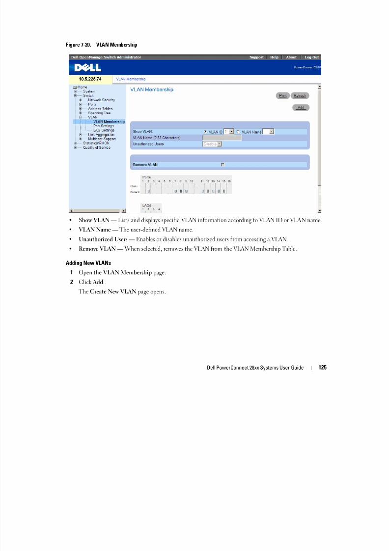
8/21/2019 Powerconnect-2824 User's Guide en-us
http://slidepdf.com/reader/full/powerconnect-2824-users-guide-en-us 125/184
Dell PowerConnect 28xx Systems User Guide 125
• Show VLAN — Lists and displays specific VLAN information according to VLAN ID or VLAN name.
• VLAN Name — The user-defined VLAN name.
• Unauthorized Users — Enables or disables unauthorized users from accessing a VLAN.
• Remove VLAN — When selected, removes the VLAN from the VLAN Membership Table.
Adding New VLANs
1 Open the VLAN Membership page.
2 Click Add.
The Create New VLAN page opens.
Figure 7-21. Create New VLAN
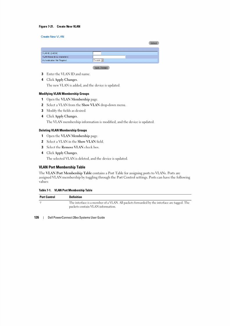
8/21/2019 Powerconnect-2824 User's Guide en-us
http://slidepdf.com/reader/full/powerconnect-2824-users-guide-en-us 126/184
126 Dell PowerConnect 28xx Systems User Guide
3 Enter the VLAN ID and name.
4 Click Apply Changes.
The new VLAN is added, and the device is updated.
Modifying VLAN Membership Groups
1 Open the VLAN Membership page.
2 Select a VLAN from the Show VLAN drop-down menu.
3 Modify the fields as desired.4 Click Apply Changes.
The VLAN membership information is modified, and the device is updated.
Deleting VLAN Membership Groups
1 Open the VLAN Membership page.
2 Select a VLAN in the Show VLAN field.
3 Select the Remove VLAN check box.
4 Click Apply Changes.
The selected VLAN is deleted, and the device is updated.
VLAN Port Membership Table
The VLAN Port Membership Table contains a Port Table for assigning ports to VLANs. Ports are
assigned VLAN membership by toggling through the Port Control settings. Ports can have the followingvalues:
Table 7-1. VLAN Port Membership Table
Port Control Definition
T The interface is a member of a VLAN. All packets forwarded by the interface are tagged. Thepackets contain VLAN information.
The VLAN Port Membership Table displays the ports and the ports states, as well as LAGs. Ports whichare LAG members are not displayed in the VLAN Port Membership Table.
U The interface is a VLAN member. Packets forwarded by the interface are untagged.
F The interface is denied membership to a VLAN.
Blank The interface is not a VLAN member. Packets associated with the interface are notforwarded.
Table 7-1. VLAN Port Membership Table
Port Control Definition

8/21/2019 Powerconnect-2824 User's Guide en-us
http://slidepdf.com/reader/full/powerconnect-2824-users-guide-en-us 127/184
Dell PowerConnect 28xx Systems User Guide 127
Assigning Ports to a VLAN Group
1 Open the VLAN Membership page.
2 Click the VLAN ID or VLAN Name option button and select a VLAN from the drop-down menu.
3 Select a port in the Port Membership Table, and assign the port a value.
4 Click Apply Changes.
The port is assigned to the VLAN group, and the device is updated.
Deleting a VLAN
1 Open the VLAN Membership page.
2 Click the VLAN ID or VLAN Name option button and select a VLAN from the drop-down menu.
3 Select the Remove VLAN check box.
4 Click Apply Changes.
The selected VLAN is deleted, and the device is updated.
Defining VLAN Ports Settings
The VLAN Port Settings page contains fields for managing ports that are part of a VLAN. The portdefault VLAN ID (PVID) is configured on the VLAN Port Settings page. All untagged packets arriving tothe device are tagged by the ports PVID.
To open the VLAN Port Settings page, click Switch VLAN Port Settings in the tree view.
Figure 7-22. VLAN Port Settings
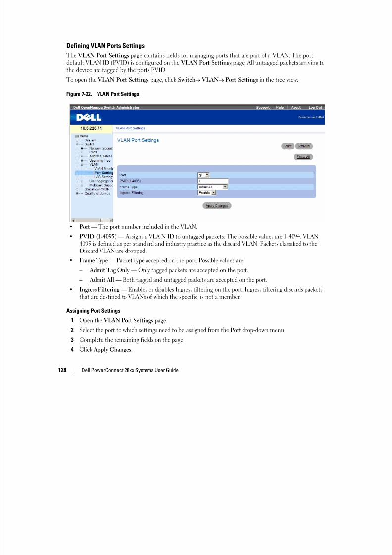
8/21/2019 Powerconnect-2824 User's Guide en-us
http://slidepdf.com/reader/full/powerconnect-2824-users-guide-en-us 128/184
128 Dell PowerConnect 28xx Systems User Guide
• Port — The port number included in the VLAN.
• PVID (1-4095) — Assigns a VLA N ID to untagged packets. The possible values are 1-4094. VLAN
4095 is defined as per standard and industry practice as the discard VLAN. Packets classified to theDiscard VLAN are dropped.
• Frame Type — Packet type accepted on the port. Possible values are:
– Admit Tag Only — Only tagged packets are accepted on the port.
– Admit All — Both tagged and untagged packets are accepted on the port.
• Ingress Filtering — Enables or disables Ingress filtering on the port. Ingress filtering discards packetsthat are destined to VLANs of which the specific is not a member.
Assigning Port Settings
1 Open the VLAN Port Settings page.
2 Select the port to which settings need to be assigned from the Port drop-down menu.
3 Complete the remaining fields on the page
4 Click Apply Changes.
The VLAN port settings are defined, and the device is updated.
Displaying the VLAN Port Table
1 Open the VLAN Port Settings page.
2 Click Show All.
The VLAN Port Table opens.
Figure 7-23. VLAN Port Table

8/21/2019 Powerconnect-2824 User's Guide en-us
http://slidepdf.com/reader/full/powerconnect-2824-users-guide-en-us 129/184
Dell PowerConnect 28xx Systems User Guide 129
Defining VLAN LAG Settings
The VLAN LAG Setting page provides parameters for managing LAGs that are part of a VLAN. VLANscan either be composed of individual ports or of LAGs. Untagged packets entering the device are taggedwith the LAGs ID specified by the PVID. To open the VLAN LAG Setting page, click Switch VLAN LAG Settings in the tree view.
Figure 7-24. VLAN LAG Setting

8/21/2019 Powerconnect-2824 User's Guide en-us
http://slidepdf.com/reader/full/powerconnect-2824-users-guide-en-us 130/184
130 Dell PowerConnect 28xx Systems User Guide
• LAG — The LAG number included in the VLAN.
• PVID — Assigns a VLAN ID to untagged packets. The possible field values are 1-4095. VLAN 4095 isdefined as per standard and industry practice, as the Discard VLAN. Packets classified to this VLAN aredropped.
• Frame Type — Packet type accepted by the LAG. Possible values are:
– Admit Tag Only — Only tagged packets are accepted by the LAG.
– Admit All — Tagged and untagged packets are both accepted by the LAG.
• Ingress Filtering — Enables or disables Ingress filtering by the LAG. Ingress filtering discards packets
that are destined to VLANs of which the specific is not a member.
Assigning VLAN LAG Settings:
1 Open the VLAN LAG Setting page.
2 Select a LAG from the LAG drop-down menu and complete the fields on the page.
3 Click Apply Changes.
The VLAN LAG parameters are defined, and the device is updated.
Displaying the VLAN LAG Table
1 Open the VLAN LAG Setting page.
2 Click Show All.
The VLAN LAG Table opens.
Aggregating PortsPort Aggregation optimizes port usage by linking a group of ports together to form a single Link
Aggregated Group (LAG). Port Aggregation multiplies the bandwidth between the devices, increases
port flexibility, and provides link redundancy. The device supports up to eight LAGs, and each LAG canhave up to eight members.
Each LAG is composed of ports of the same speed, set to full-duplex operations. Ports in a LAG can be ofdifferent media types (UTP/Fiber, or different fiber types), provided they operate at the same speed.
The device provides LAG Load Balancing based on both source MAC addresses and destination MACaddresses.
Aggregated Links are treated by the system as a single logical port. Specifically, the Aggregated Link has
8/21/2019 Powerconnect-2824 User's Guide en-us
http://slidepdf.com/reader/full/powerconnect-2824-users-guide-en-us 131/184
Dell PowerConnect 28xx Systems User Guide 131
similar port attributes to a non-aggregated port, including auto-negotiation, speed, etc.The following guidelines should be followed when adding ports to a LAG:
• There is no Layer 3 interface defined on the port.
• The port does not belong to any VLAN.
• The port does not belong to any other LAG.
• The port is not a mirrored port.
• The port's 802.1p priority is equal to LAGs 802.1p priority.• QoS Trust is not disabled on the port.
• GVRP is not enabled.
The device uses a hash function to determine which frames are carried on which aggregated-linkmember. The hash function statistically load-balances the aggregated link members. The deviceconsiders an Aggregated Link as a single logical port.
Each Aggregated Link has an Aggregated Link Port Type, including Gigabit Ethernet ports. Ports can be
added to an Aggregated Link only if they are the same port type. When ports are removed from an Aggregated Links, the ports revert to the original port settings. To open the Link Aggregation page, clickSwitch Link Aggregation in the tree view.
Defining LAG Membership
The LAG Membership page contains fields for assigning ports to LAGs. LAGs can include up to eightports. When a port is added to a LAG, the port acquires the LAG’s properties. If the port cannot beconfigured with the LAG properties, a trap is generated and the port operates with its default settings.
The LAG Membership page contains fields for assigning ports to LAGs. To open the LAG Membership page, click Switch Link Aggregation LAG Membership in the tree view.
Figure 7-25. LAG Membership

8/21/2019 Powerconnect-2824 User's Guide en-us
http://slidepdf.com/reader/full/powerconnect-2824-users-guide-en-us 132/184
132 Dell PowerConnect 28xx Systems User Guide
• LAG — Adds a port to a LAG, and indicates the specific LAG to which the port belongs.
Configuring a Port to a LAG
1 Open the LAG Membership page.
2 In the LAG row (the second row), toggle the button to a specific number to aggregate to or remove the
port from that LAG number.3 Click Apply Changes.
The port is added to the LAG, and the device is updated.
Multicast Forwarding SupportMulticast forwarding allows a single packet to be forwarded to multiple destinations. L2 Multicast service
is based on L2 switch receiving a single packet addressed to a specific Multicast address. Multicastforwarding creates copies of the packet, and transmits the packets to the relevant ports.
To open the Multicast Support page, click Switch Multicast Support in the tree view.
Defining Multicast Global Parameters
Layer 2 switching forwards Multicast packets to all relevant VLAN ports by default, treating the packet asa Multicast transmission. While this is functional, in the sense that all relevant ports/nodes receive acopy of the frame, it is potentially wasteful as ports/nodes may receive irrelevant frames only needed by a
subset of the ports of that VLAN. Multicast forwarding filters enable forwarding of Layer 2 packets toport subsets, defined in the Multicast filter database.
When IGMP snooping is enabled globally, the switching ASIC is programmed to forward all IGMPpackets to the CPU. The CPU analyzes the incoming packets and determines which ports are to joinwhich Multicast groups, which ports have Multicast routers generating IGMP queries, and what routingprotocols are forwarding packets and Multicast traffic. Ports requesting to join a specific Multicast groupissues an IGMP report specifying that Multicast group. This results in the creation of the Multicast
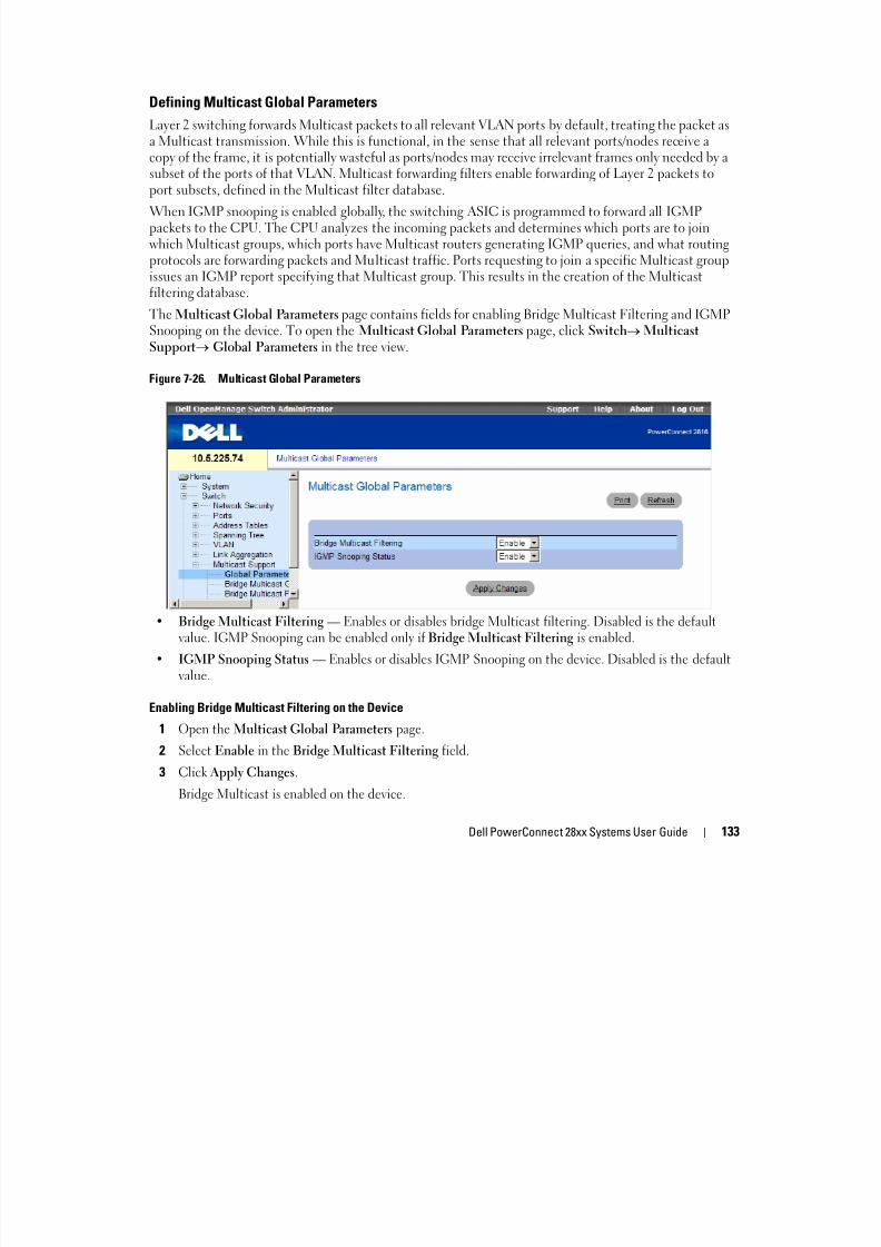
8/21/2019 Powerconnect-2824 User's Guide en-us
http://slidepdf.com/reader/full/powerconnect-2824-users-guide-en-us 133/184
Dell PowerConnect 28xx Systems User Guide 133
filtering database.The Multicast Global Parameters page contains fields for enabling Bridge Multicast Filtering and IGMPSnooping on the device. To open the Multicast Global Parameters page, click Switch MulticastSupport Global Parameters in the tree view.
Figure 7-26. Multicast Global Parameters
• Bridge Multicast Filtering — Enables or disables bridge Multicast filtering. Disabled is the defaultvalue. IGMP Snooping can be enabled only if Bridge Multicast Filtering is enabled.
• IGMP Snooping Status — Enables or disables IGMP Snooping on the device. Disabled is the defaultvalue.
Enabling Bridge Multicast Filtering on the Device
1 Open the Multicast Global Parameters page.
2 Select Enable in the Bridge Multicast Filtering field.
3 Click Apply Changes.
Bridge Multicast is enabled on the device.
Enabling IGMP Snooping on the Device
1 Open the Multicast Global Parameters page.
2 Select Enable in the IGMP Snooping Status field.
3 Click Apply Changes.IGMP Snooping is enabled on the device.
Adding Bridge Multicast Address Members
The Bridge Multicast Group page displays the ports and LAGs attached to the Multicast service groupin the Ports and LAGs tables. The Port and LAG tables also reflect the manner in which the port orLAGs joined the Multicast group. Ports can be added either to existing groups or to new Multicast
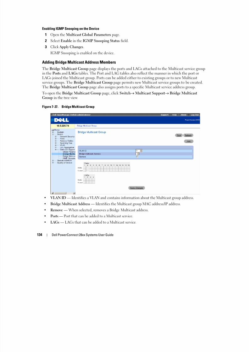
8/21/2019 Powerconnect-2824 User's Guide en-us
http://slidepdf.com/reader/full/powerconnect-2824-users-guide-en-us 134/184
134 Dell PowerConnect 28xx Systems User Guide
service groups. The Bridge Multicast Group page permits new Multicast service groups to be created.The Bridge Multicast Group page also assigns ports to a specific Multicast service address group.
To open the Bridge Multicast Group page, click Switch Multicast Support Bridge MulticastGroup in the tree view.
Figure 7-27. Bridge Multicast Group
• VLAN ID — Identifies a VLAN and contains information about the Multicast group address.
• Bridge Multicast Address — Identifies the Multicast group MAC address/IP address.
• Remove — When selected, removes a Bridge Multicast address.
• Ports — Port that can be added to a Multicast service.
• LAGs — LAGs that can be added to a Multicast service.
The following table contains the IGMP port and LAG members management settings:
D The port/LAG has joined the Multicast groupdynamically in the Current Row.
F The port/LAG is excluded from this Multicastgroup.
S Attaches the port to the Multicast group asstatic member in the Static Row.
The port/LAG has joined the Multicast groupstatically in the Current Row.
Blank The port is not attached to a Multicast group.

8/21/2019 Powerconnect-2824 User's Guide en-us
http://slidepdf.com/reader/full/powerconnect-2824-users-guide-en-us 135/184
Dell PowerConnect 28xx Systems User Guide 135
Adding Bridge Multicast Addresses
1 Open the Bridge Multicast Group page.
2 Click Add.
The Add Bridge Multicast Group page opens:
Figure 7-28. Add Bridge Multicast Group
3 Define the VLAN ID and New Bridge Multicast Address fields.
4 Toggle a port to S to join the port to the selected Multicast group.
5 Toggle a port to F to forbid adding specific Multicast addresses to a specific port.
6 Click Apply Changes.
The bridge Multicast address is assigned to the Multicast group, and the device is updated.
Defining Ports to Receive Multicast Service
1 Open the Bridge Multicast Group page.
2 Define the VLAN ID and the Bridge Multicast Address fields.
3 Toggle a port to S to join the port to the selected Multicast group.
4 Toggle a port to F to forbid adding specific Multicast addresses to a specific port.
5 Click Apply Changes.
The port is assigned to the Multicast group, and the device is updated.

8/21/2019 Powerconnect-2824 User's Guide en-us
http://slidepdf.com/reader/full/powerconnect-2824-users-guide-en-us 136/184
136 Dell PowerConnect 28xx Systems User Guide
Assigning LAGs to Receive Multicast Service
1 Open the Bridge Multicast Group page.
2 Define the VLAN ID and the Bridge Multicast Address fields.
3 Toggle the LAG to S to join the LAG to the selected Multicast group.
4 Toggle the LAG to F to forbid adding specific Multicast addresses to a specific LAG.
5 Click Apply Changes.The LAG is assigned to the Multicast group, and the device is updated.
Assigning Multicast Forward All Parameters
The Bridge Multicast Forward All page contains fields for attaching ports or LAGs to a device that isattached to a neighboring Multicast router/switch. Once IGMP Snooping is enabled, Multicast packetsare forwarded to the appropriate port or VLAN.
To open the Bridge Multicast Forward All page, click Switch Multicast Support Bridge MulticastForward All page in the tree view.
Figure 7-29. Bridge Multicast Forward All

8/21/2019 Powerconnect-2824 User's Guide en-us
http://slidepdf.com/reader/full/powerconnect-2824-users-guide-en-us 137/184
Dell PowerConnect 28xx Systems User Guide 137
• VLAN ID — Identifies a VLAN.• Ports — Ports that can be added to a Multicast service.
• LAGs — LAGs that can be added to a Multicast service.
The contains the settings for managing router and port settings.
Port Control Definition
F The port/LAG is excluded from this Multicastgroup.
S Attaches the port to the Multicast router orswitch as a static port.
Blank The port is not attached to a Multicast router orswitch.
Attaching a Port to a Multicast Router or Switch
1 Open Bridge Multicast Forward All page.
2 Define the VLAN ID field.
3 Select a port in the Ports table, and assign the port a value.4 Click Apply Changes.
The port is attached to the Multicast router or switch.
Attaching a LAG to a Multicast Router or Switch
1 Open Bridge Multicast Forward All page.
2 Define the VLAN ID field.
3 S l i h LAG bl d i h LAG l

8/21/2019 Powerconnect-2824 User's Guide en-us
http://slidepdf.com/reader/full/powerconnect-2824-users-guide-en-us 138/184
138 Dell PowerConnect 28xx Systems User Guide
3 Select a port in the LAGs table, and assign the LAG a value.
4 Click Apply Changes.
The LAG is attached to the Multicast router or switch.
IGMP Snooping
The IGMP Snooping page contains fields for adding IGMP members. To open the IGMP Snooping page, click Switch Multicast Support IGMP Snooping in the tree view.
Figure 7-30. IGMP Snooping

8/21/2019 Powerconnect-2824 User's Guide en-us
http://slidepdf.com/reader/full/powerconnect-2824-users-guide-en-us 139/184
Dell PowerConnect 28xx Systems User Guide 139
• VLAN ID — Specifies the VLAN ID.
• IGMP Snooping Status — Enables or disables IGMP snooping on the VLAN.
• Auto Learn — Enables or disables Auto Learn on the device.
• IGMP Querier Status — Enables or disables the IGMP Querier. The IGMP Querier simulates thebehavior of a multicast router, allowing snooping of the layer 2 multicast domain even though there isno multicast router.
• Querier IP Address — IP address of the IGMP Querier. Use either use the VLAN’s IP Interface addressor define a unique IP address which will be used as a source address of Querier.
• Host Timeout (1-2147483647) — Time before an IGMP snooping entry is aged out. The default timeis 260 seconds.
• Multicast Router Timeout (1-2147483647) — Time before aging out a Multicast router entry. Thedefault value is 300 seconds.
• Leave Timeout (0-2147483647) — Time, in seconds, after a port leave message is received before theentry is aged out. User-defined enables a user-definable timeout period, and Immediate Leave specifies an immediate timeout period. The default timeout is 10 seconds.
Enabling IGMP Snooping on the Device
1 Open the IGMP Snooping page.
2 Select the VLAN ID for the device on which IGMP snooping needs to be enabled.
3 Select Enable in the IGMP Snooping Status field.4 Complete the fields on the page.
5 Click Apply Changes.
IGMP snooping is enabled on the device.
Displaying the IGMP Snooping Table
1 Open the IGMP Snooping.
2 Click Show All
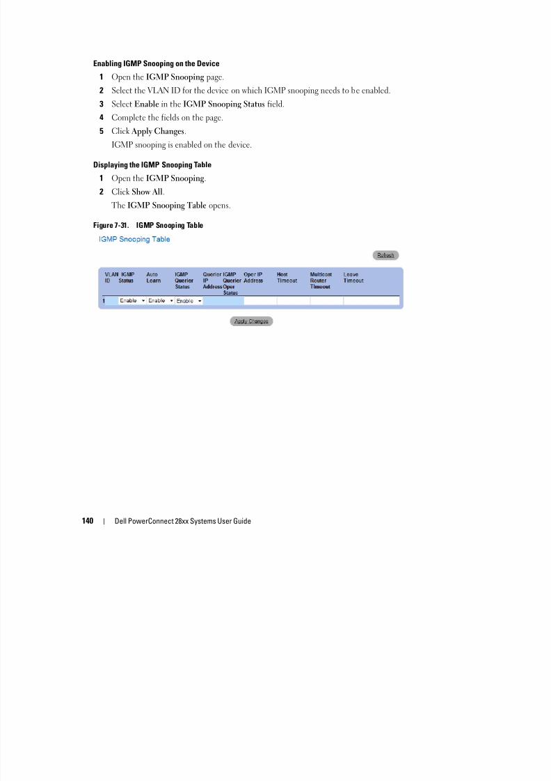
8/21/2019 Powerconnect-2824 User's Guide en-us
http://slidepdf.com/reader/full/powerconnect-2824-users-guide-en-us 140/184
140 Dell PowerConnect 28xx Systems User Guide
2 Click Show All.
The IGMP Snooping Table opens.
Figure 7-31. IGMP Snooping Table
8Viewing StatisticsThe Statistic pages contain links to device information for RMON, and CPU utilization.
Viewing RMON StatisticsRemote Monitoring (RMON) contains links for viewing network information from a remotelocation. To open the RMON page, click Statistics/RMON RMON in the tree view.
Viewing RMON Statistics Group

8/21/2019 Powerconnect-2824 User's Guide en-us
http://slidepdf.com/reader/full/powerconnect-2824-users-guide-en-us 141/184
Dell PowerConnect 28xx Systems User Guide 141
Viewing RMON Statistics GroupThe RMON Statistics Group page contains fields for viewing information about device utilizationand errors that occurred on the device. To open the RMON Statistics Group page, clickStatistics/RMON RMON Statistics in the tree view.
Figure 8-1. RMON Statistics Group
• Interface — Specifies the port or LAG for which statistics are displayed.
• Refresh Rate — Amount of time that passes before the statistics are refreshed.
• — Number of dropped that have occurred on the interface since the device was last refreshed.
• Received Bytes (Octets) — Number of octets received on the interface since the device was lastrefreshed. This number includes bad packets and FCS octets, but excludes framing bits.
• Received Packets — Number of packets received on the interface, including bad packets, Multicastand broadcast packets, since the device was last refreshed.
• Broadcast Packets Received — Number of good broadcast packets received on the interface since thedevice was last refreshed. This number does not include Multicast packets.
• Multicast Packets Received — Number of good Multicast packets received on the interface since thedevice was last refreshed.
• CRC & Align Errors — Number of CRC and Align errors that have occurred on the interface since thedevice was last refreshed.
• Undersize Packets — Number of undersized packets (less than 64 octets) received on the interfacesince the device was last refreshed

8/21/2019 Powerconnect-2824 User's Guide en-us
http://slidepdf.com/reader/full/powerconnect-2824-users-guide-en-us 142/184
142 Dell PowerConnect 28xx Systems User Guide
since the device was last refreshed.
• Oversize Packets — Number of oversized packets (over 1518 octets) received on the interface since thedevice was last refreshed.
• Fragments — Number of fragments (packets with less than 64 octets, excluding framing bits, butincluding FCS octets) received on the interface since the device was last refreshed.
• Jabbers — Number of jabbers (packets longer than 1518 octets) received on the interface since thedevice was last refreshed.
• Collisions — Number of collisions received on the interface since the device was last refreshed.
• Frames of Bytes — Number of xx -byte frames received on the interface since the device was lastrefreshed.
Viewing Interface Statistics
1 Open the RMON Statistics Group page.
2 Select an interface type and number in the Interface field.The interface statistics are displayed.
Viewing ChartsThe Chart page contains links for displaying statistics in a chart form. To open the page, clickStatistics Charts in the tree view.
Viewing the CPU Utilization
The CPU Utilization page contains information about the system’s CPU utilization and percentage ofCPU resources consumed by
The range of the utilization reading is from 0 to 100%.
To open the CPU Utilization page, click Statistics/RMON Charts CPU Utilization in the treeview.
Figure 8-2. CPU Utilization
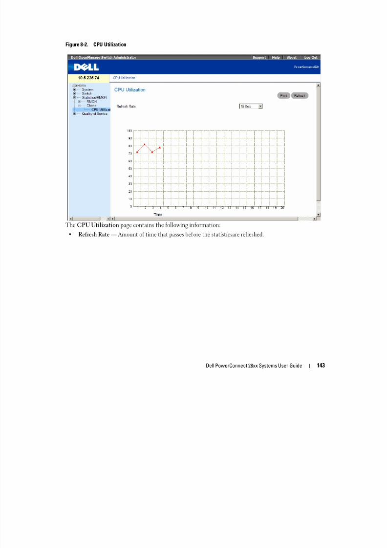
8/21/2019 Powerconnect-2824 User's Guide en-us
http://slidepdf.com/reader/full/powerconnect-2824-users-guide-en-us 143/184
Dell PowerConnect 28xx Systems User Guide 143
The CPU Utilization page contains the following information:
• Refresh Rate — Amount of time that passes before the statisticsare refreshed.
9Configuring Quality of ServiceThis section provides information for defining and configuring Quality of Service (QoS) parameters.To open the Quality of Service page, click Quality of Service in the tree view.
An implementation example that requires QoS includes certain types of traffic such as Voice, Videoand real-time traffic which can be assigned a high priority queue, while other traffic can be assigneda lower priority queue. The result is an improved traffic flow for traffic with high demand.
QoS is defined by:
• Classification — Specifies which packet fields are matched to specific values. All packetst hi th d fi d ifi ti l ifi d t th

8/21/2019 Powerconnect-2824 User's Guide en-us
http://slidepdf.com/reader/full/powerconnect-2824-users-guide-en-us 144/184
Dell PowerConnect 28xx Systems User Guide 144
p p p pmatching the user-defined specifications are classified together.
• Action — Defines traffic management where packets being forwarded are based on packetinformation, and packet field values such as VLAN priority (VPT) and DSCP (DiffServ CodePoint).
VPT Tag Classification Information
VLAN Priority Tags are used to classify the packets by mapping packets to one of the output queues.VLAN Priority Tag to queue assignments are user-definable. The table below details the VPT toqueue default settings:
Packets arriving untagged are assigned a default VPT that is set on a per port basis. The assignedVPT is used to map the packet to the output queue and as the egress VPT.
Table 9-1. CoS to Queue Mapping Table Default values
CoS Value Forwarding Queue Values
0 q
1 q1
2 q1
3 q
4 q
5 q
6 q
7 q
DSCP values can be mapped to priority queues. The following table contains the default DSCP mappingto forwarding queue values:
DSCP mapping is enabled on a per-system basis.
Table 9-2. DSCP to Queue Mapping Table Default Values
DSCP Value Forwarding Queue Values
0- q1
q2
q3
q4
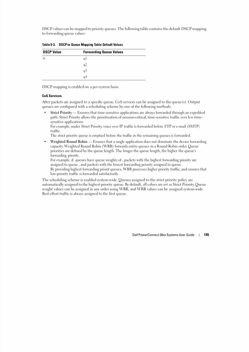
8/21/2019 Powerconnect-2824 User's Guide en-us
http://slidepdf.com/reader/full/powerconnect-2824-users-guide-en-us 145/184
Dell PowerConnect 28xx Systems User Guide 145
CoS Services
After packets are assigned to a specific queue, CoS services can be assigned to the queue(s). Outputqueues are configured with a scheduling scheme by one of the following methods:
• Strict Priority — Ensures that time-sensitive applications are always forwarded through an expeditedpath. Strict Priority allows the prioritization of mission-critical, time-sensitive traffic over less time-
sensitive applications.For example, under Strict Priority, voice over IP traffic is forwarded before FTP or e-mail (SMTP)traffic.The strict priority queue is emptied before the traffic in the remaining queues is forwarded.
• Weighted Round Robin — Ensures that a single application does not dominate the device forwardingcapacity. Weighted Round Robin (WRR) forwards entire queues in a Round Robin order. Queuepriorities are defined by the queue length. The longer the queue length, the higher the queue'sforwarding priority.For example, if queues have queue weights of , packets with the highest forwarding priority areassigned to queue , and packets with the lowest forwarding priority assigned to queue .By providing highest forwarding priorit queues, WRR processes higher priority traffic, and ensures thatlow-priority traffic is forwarded satisfactorily.
The scheduling scheme is enabled system-wide. Queues assigned to the strict priority policy areautomatically assigned to the highest priority queue. By default, all values are set as Strict Priority. Queueweight values can be assigned in any order using WRR, and WRR values can be assigned system-wide.
Best effort traffic is always assigned to the first queue.
Defining CoS Global ParametersThis section contains the following topics:
• Defining CoS Settings
• Defining QoS Interface Settings• Defining Queue Settings
• Mapping CoS Values to Queues
• Mapping DSCP Values to Queues
Defining CoS Settings
Defining CoS Settings

8/21/2019 Powerconnect-2824 User's Guide en-us
http://slidepdf.com/reader/full/powerconnect-2824-users-guide-en-us 146/184
146Dell PowerConnect 28xx Systems User Guide
Class of Service (CoS) global parameters are set from the CoS Settings page.
To open the CoS Settings page, click Quality of Service CoS Global Parameters CoS Settings inthe tree view.
Figure 9-1. CoS Settings
• Cos Mode — Enables or disables managing network traffic using Quality of Service.
• Trust Mode — Determines which packet fields to use for classifying packets entering the device.When no rules are defined, the traffic containing the predefined packet field (CoS or DSCP) is
mapped according to the relevant trust modes table. Traffic not containing a predefined packet field ismapped to best effort. The possible Trust mode field values are:
– CoS (802.1P) — The output queue assignment is determined by the IEEE802.1p VLAN prioritytag (VPT) or by the default VPT assigned to a port.
– DSCP — The output queue assignment is determined by the DSCP field.
Enabling Quality of Service:
1 Open the CoS Settings page.
2 Select Enable in the CoS Mode field.
3 Click Apply Changes.
Class of Service is enabled on the device.
Selecting Trust:
1 Open the CoS Settings page.
2 Select Trust in the Trust Mode field.
3 Click Apply Changes.
Trust is selected.
Defining QoS Interface Settings
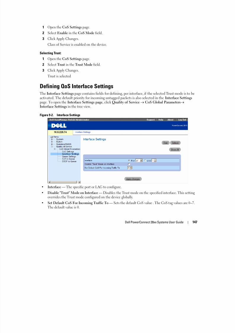
8/21/2019 Powerconnect-2824 User's Guide en-us
http://slidepdf.com/reader/full/powerconnect-2824-users-guide-en-us 147/184
Dell PowerConnect 28xx Systems User Guide 147
Defining QoS Interface SettingsThe Interface Settings page contains fields for defining, per interface, if the selected Trust mode is to beactivated. The default priority for incoming untagged packets is also selected in the Interface Settings page. To open the Interface Settings page, click Quality of Service CoS Global Parameters Interface Settings in the tree view.
Figure 9-2. Interface Settings
• Interface — The specific port or LAG to configure.
• Disable "Trust" Mode on Interface — Disables the Trust mode on the specified interface. This settingoverrides the Trust mode configured on the device globally.
• Set Default CoS For Incoming Traffic To — Sets the default CoS value . The CoS tag values are 0–7.The default value is 0.
Assigning QoS/CoS settings for an interface:
1 Open the Interface Settings page.
2 Select an interface in the Interface field.
3 Define the fields.
4 Click Apply Changes.
The CoS settings are assigned to the interface.
Displaying the QoS Interface Settings Table:
1 Open the Interface Settings page.
2 Click Show All.
The QoS Interface Settings Table page opens:
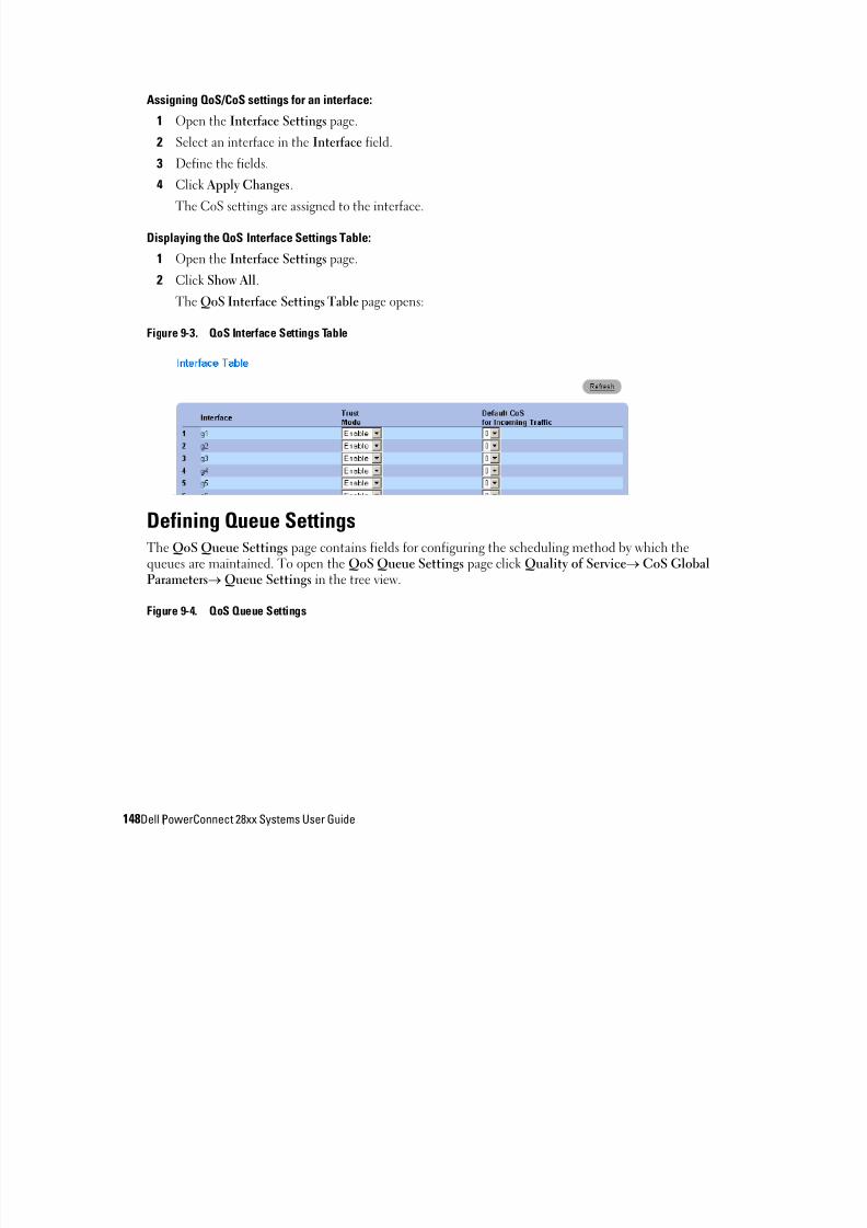
8/21/2019 Powerconnect-2824 User's Guide en-us
http://slidepdf.com/reader/full/powerconnect-2824-users-guide-en-us 148/184
148Dell PowerConnect 28xx Systems User Guide
Figure 9-3. QoS Interface Settings Table
Defining Queue Settings
The QoS Queue Settings page contains fields for configuring the scheduling method by which thequeues are maintained. To open the QoS Queue Settings page click Quality of Service CoS GlobalParameters Queue Settings in the tree view.
Figure 9-4. QoS Queue Settings

8/21/2019 Powerconnect-2824 User's Guide en-us
http://slidepdf.com/reader/full/powerconnect-2824-users-guide-en-us 149/184
Dell PowerConnect 28xx Systems User Guide 149
• Queues — The Queue number.
• Strict Priority — Specifies if traffic scheduling is based strictly on the queue priority.
• WRR — Specifies if traffic scheduling is based on the Weighted Round Robin (WRR) weights toegress queues. The default values are:
– 1 for Queue 1
– 2 for Queue 2
– 8 for Queue 3
– 16 for Queue 4
• WRR Weights — The WRR weight assigned to each queue.
• WRR Percentage — The WRR percentage of each queue.
Defining the Queue Settings
1 Open the QoS Queue Settings page.
2 Define the fields.
3 Click Apply Changes.
The queue settings are defined, and the device is updated.
Mapping CoS Values to QueuesThe CoS to Queue Mapping Table page contains fields for classifying CoS settings to traffic queues. Toopen the CoS to Queue Mapping Table page, click Quality of ServiceCoS Global Parameters CoSto Queue in the tree view.
Figure 9-5. CoS to Queue Mapping Table

8/21/2019 Powerconnect-2824 User's Guide en-us
http://slidepdf.com/reader/full/powerconnect-2824-users-guide-en-us 150/184
150Dell PowerConnect 28xx Systems User Guide
• Class of Service — Specifies the CoS priority tag values, where zero is the lowest value and 7 is the
highest value.• Queue — The traffic forwarding queue to which the CoS priority is mapped. Four traffic priority
queues are supported.
Restore Defaults — Restores the device factory defaults for mapping CoS values to a forwarding queue.Mapping a CoS value to a Queue
1 Open the CoS to Queue Mapping Table page.
2 Select a CoS entry.3 Define the queue number in the Queue field.
4 Click Apply Changes.
The CoS value is mapped to a queue, and the device is updated.
Mapping DSCP Values to QueuesThe DSCP to Queue page provides fields for defining output queue to specific DSCP fields. For the listof the DSCP default queue settings, see "DSCP to Queue Mapping Table Default Values" on page 145.To open the DSCP to Queue page, click Quality of Service CoS Global Parameters DSCP to
Queue in the tree view.
Figure 9-6. DSCP to Queue
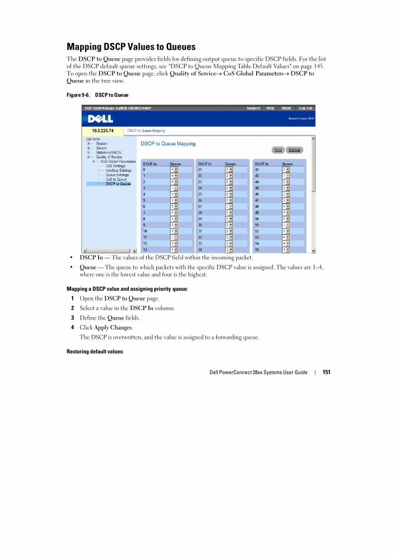
8/21/2019 Powerconnect-2824 User's Guide en-us
http://slidepdf.com/reader/full/powerconnect-2824-users-guide-en-us 151/184
Dell PowerConnect 28xx Systems User Guide 151
• DSCP In — The values of the DSCP field within the incoming packet.
• Queue — The queue to which packets with the specific DSCP value is assigned. The values are 1–4,where one is the lowest value and four is the highest.
Mapping a DSCP value and assigning priority queue:
1 Open the DSCP to Queue page.
2 Select a value in the DSCP In column.3 Define the Queue fields.
4 Click Apply Changes.
The DSCP is overwritten, and the value is assigned to a forwarding queue.
Restoring default values:
1 Open the DSCP to Queue page.
2 Check the Restore Defaults checkbox.
3 Click Apply Changes.
The default values are restored.

8/21/2019 Powerconnect-2824 User's Guide en-us
http://slidepdf.com/reader/full/powerconnect-2824-users-guide-en-us 152/184
152Dell PowerConnect 28xx Systems User Guide
AManaging the Device Using the CLI
A limited number of CLI commands are available for managing the device. These commands are asubset of the options available via the web interface.
Accessing the Device Through the CLIThe device can be managed over a direct connection to the console port or via a Telnet connection.Using the CLI is similar to entering commands on a Linux system. If access is via a Telnet
connection, ensure the device has an IP address defined and that the workstation used to access thedevice is connected to the device prior to beginning using CLI commands.
f b f l P Add "S P Add d S b k "
8/21/2019 Powerconnect-2824 User's Guide en-us
http://slidepdf.com/reader/full/powerconnect-2824-users-guide-en-us 153/184
Dell PowerConnect 28xx Systems User Guide 153
For information about configuring an initial IP Address, see "Static IP Address and Subnet Mask."
NOTE: Ensure the client is loaded, before using the CLI.
NOTE: CLI can be used to manage the device only when the device is in Managed mode. For more
information about management modes, see "Management Modes" on page 50.
Console Connection1 Power on the device and wait until the startup is complete.
2 When the Console> prompt displays, type enable and press <Enter>.
3 Configure the device and enter the necessary commands to complete the required tasks.
4 When finished, exit the session with the quit or exit command.
NOTE: If a different user logs into the system in the Privilege EXEC command mode, the current user is logged
off and the new user is logged in.
Telnet Connection
Telnet is a terminal emulation TCP/IP protocol. ASCII terminals can be virtually connected to thelocal device through a TCP/IP protocol network. Telnet is an alternative to a local login terminalwhere a remote login is required.
The device supports up to four simultaneous Telnet sessions. All CLI commands can be used over a
telnet session.To start a Telnet session:
1 Select Start > Run.
The Run window opens.
2 In the Run window, type Telnet <IP address> in the Open field.
3 Click OK to begin the Telnet session.
Using the CLIThis section provides information for using the CLI.
Command Mode Overview
The CLI is divided into command modes. Each command mode has a specific command set. Entering aquestion mark at the console prompt displays a list of commands available for that particular commandmode.
In each mode, a specific command is used to navigate from one command mode to another.During the CLI session initialization, the CLI mode is the User EXEC mode. Only a limited subset ofcommands are available in the User EXEC mode This level is reserved for tasks that do not change the

8/21/2019 Powerconnect-2824 User's Guide en-us
http://slidepdf.com/reader/full/powerconnect-2824-users-guide-en-us 154/184
154 Dell PowerConnect 28xx Systems User Guide
commands are available in the User EXEC mode. This level is reserved for tasks that do not change theconsole configuration and is used to access configuration sub-systems such as the CLI. To enter the nextlevel, the Privileged EXEC mode, a password is required (if configured).
The Privileged EXEC mode provides access to the device global configuration. For specific globalconfigurations within the device, enter the next level, Global Configuration mode. A password is notrequired.
The Global Configuration mode manages the device configuration on a global level.
The Interface Configuration mode configures the device at the physical interface level. Interfacecommands, which require subcommands, have another level called the Subinterface Configurationmode. A password is not required.
User EXEC Mode
After logging into the device, the EXEC command mode is enabled. The user-level prompt consists ofthe host name followed by the angle bracket (>). For example:
console>
NOTE: The default host name is console unless it has been modified during initial configuration.
The user EXEC commands permit connecting to remote devices, changing terminal settings on atemporary basis, performing basic tests, and listing system information.
To list the user EXEC commands, enter a question mark at the command prompt.
Privileged EXEC Mode
Privileged access can be protected to prevent unauthorized access and ensure operating parameters.Passwords are displayed in the ***** format on the screen, and are case sensitive.
To access and list the Privileged EXEC Mode commands:
1 At the prompt type enable and press <Enter>.
2 When a password prompt displays, enter the password and press <Enter>.
The Privileged EXEC mode prompt displays as the device host name followed by #. For example:
console#
To list the Privileged EXEC commands, type a question mark at the command prompt and press<Enter>.
To return from Privileged EXEC Mode to User EXEC Mode use any of the following commands:disable, exit/end, or <Ctrl><Z>.
8/21/2019 Powerconnect-2824 User's Guide en-us
http://slidepdf.com/reader/full/powerconnect-2824-users-guide-en-us 155/184
Dell PowerConnect 28xx Systems User Guide 155
, ,
The following example illustrates accessing privileged EXEC mode and then returning to the UserEXEC mode:
console>enable
Enter Password: ******
console#
console#disable
console>
Use the exit command to move back to a previous mode. For example, from Interface Configurationmode to Global Configuration mode, and from Global Configuration mode to Privileged EXEC mode.
Global Configuration Mode
Global Configuration commands apply to system features, rather than a specific protocol or interface.
To access Global Configuration mode, at the Privileged EXEC Mode prompt, type configure andpress <Enter>. The Global Configuration Mode displays as the device host name followed by (config)and the pound sign #.
console(config)#
To list the Global Configuration commands, enter a question mark at the command prompt.To return from Global Configuration mode to Privileged EXEC mode, type the exit command or usethe <Ctrl><Z> command.
The following example illustrates how to access Global Configuration Mode and return back to thePrivileged EXEC Mode:
console#
console#configure
console(config)#exit
console#
Interface Configuration Mode
Interface configuration commands modify specific IP interface settings, including bridge-group,description, etc.
Interface Mode
The Interface mode contains commands that configure the interface. The Global Configuration mode

8/21/2019 Powerconnect-2824 User's Guide en-us
http://slidepdf.com/reader/full/powerconnect-2824-users-guide-en-us 156/184
156 Dell PowerConnect 28xx Systems User Guide
The Interface mode contains commands that configure the interface. The Global Configuration modecommand interface ethernet is used to enter the interface configuration mode. The following isan example of the Interface mode prompt:
console> enable
console# configure
console(config)# interface ethernet g18
console(config-if)#
VLAN Mode
The VLAN mode contains commands to create and configure a VLAN as a whole, for example, to createa VLAN and apply an IP address to the VLAN. The following is an example of the VLAN mode prompt:
Console (config)# interface vlan 1Console (config-if)#
Port Channel Mode
The Port Channel mode contains commands for configuring Link Aggregation Groups (LAG). Thefollowing is an example of the Port Channel mode prompt:
Console (config)# interface port-channel 1
Console (config-if)#
CLI Commands
Command: copy
To copy any file from a source to a destination, use the copy Privileged EXEC command.
copy source-url destination-url
Syntax Description
• source-url — The location URL or reserved keyword of the source file to be copied.
• destination-url — The destination URL or reserved keyword of the destination file.
Parameters Range
• source-url — 1 - 160 characters
• destination-url — 1 - 160 characters

8/21/2019 Powerconnect-2824 User's Guide en-us
http://slidepdf.com/reader/full/powerconnect-2824-users-guide-en-us 157/184
Dell PowerConnect 28xx Systems User Guide 157
The following table shows keywords and URL prefixes:
Command Mode
Privileged EXEC
Usage Guidelines
The location of a file system dictates the format of the source or destination URL.
The entire copying process may take several minutes and differs from protocol to protocol and fromnetwork to network.
If the egress interface is not specified, the default interface will be selected. Specifying interface zone=0is equal to not defining an egress interface.
Table A-1. Source and Destination Keywords
Keyword Source or Destination
image If source file, represent the active image file. If destination file, represent the non-active image file.
boot Boot file.
tftp: Source or destination URL for a TFTP network server. The syntax for this alias istftp: //host/[directory]/filename . The host can be IPv4 address. An out-of-band IPaddress can be specified as described in the usage guidelines.
xmodem: Source for the file from a serial connection that uses the Xmodem protocol.
null: Null destination for copies or files. You can copy a remote file to null to determineits size.
Understanding Invalid Combinations of Source and Destination
Some invalid combinations of source and destination exist. Specifically, you cannot copy the following:
• If the source file and destination file are the same file.
• xmodem: can't be destination. Can be copied to image, boot and null: only.
• tftp: can't be source and destination on the same copy.
• *.prv files can't be copied.
• Copy to or from the slave units is for image and boot files only.
copy Character Descriptions
Table A-2. Source and Destination Keywords
Character Description
F k f l i i i di h h i ki

8/21/2019 Powerconnect-2824 User's Guide en-us
http://slidepdf.com/reader/full/powerconnect-2824-users-guide-en-us 158/184
158 Dell PowerConnect 28xx Systems User Guide
Command: debug-mode
To switch to debug mode, use the debug-mode command in Privileged EXEC mode.
debug-mode
Syntax Description
This command has no arguments or keywords.
Command Mode
Privileged EXEC
Command: do
To execute an EXEC-level command from global configuration mode or any configuration submode, usethe do command in any configuration mode.
do command
Syntax Description
command — The EXEC command to be executed.
! For network transfers, an exclamation point indicates that the copy process is takingplace. Each exclamation point indicates the successful transfer of ten packets (512bytes each).
. For network transfers, a period indicates that the copy process timed out. Manyperiods in a row typically mean that the copy process may fail.
Command modes
All configuration modes
Command: end
To end the current configuration session and return to privileged EXEC mode, use the end globalconfiguration command.
end
Syntax Description
This command has no arguments or key words
Command Mode All configuration modes
8/21/2019 Powerconnect-2824 User's Guide en-us
http://slidepdf.com/reader/full/powerconnect-2824-users-guide-en-us 159/184
Dell PowerConnect 28xx Systems User Guide 159
Default value
This command has no default setting.
Example
Console(config-if)# end Console#
Command: exit (configuration)
To exit any configuration mode to the next highest mode in the CLI mode hierarchy, use the exit command in any configuration mode.
exit
Syntax Description
This command has no arguments or key words
Command Mode
All configuration modes
Default valueThis command has no default setting.
Examples
Console(config-if)# exit
Console(config)# exit
Console#
Command: exit (EXEC)
To close an active terminal session by logging off the router, use the exit command in EXEC mode.
exit
Syntax Description
This command has no arguments or key words
Command Mode
EXEC
Default value
This command has no default setting.
8/21/2019 Powerconnect-2824 User's Guide en-us
http://slidepdf.com/reader/full/powerconnect-2824-users-guide-en-us 160/184
160 Dell PowerConnect 28xx Systems User Guide
Example
Console> exit
Command: help
To display a brief description of the help system, enter the help command.
help
Syntax Description
This command has no arguments or key words
Command Mode
All command modes.
Default value
This command has no default setting.
Command: interface ethernet
To configure an interface type and enter interface configuration mode, use the interface ethernet globalconfiguration command.
interface ethernet interface
Syntax Description
• interface — The full syntax is: port .
Parameters range
• interface — Valid Ethernet port.
Command Modes
Global Configuration
Example
Console(config)# interface ethernet g1
Console(config-if)#
Command: interface port-channel
To configure a port-channel type and enter port-channel configuration mode, use the interface port- channel global configuration command.
interface port-channel port-channel-number

8/21/2019 Powerconnect-2824 User's Guide en-us
http://slidepdf.com/reader/full/powerconnect-2824-users-guide-en-us 161/184
Dell PowerConnect 28xx Systems User Guide 161
p p
Syntax Description
• port-channel-number — Port channel index.
Parameters range• port-channel-number — Valid port channel
Command Modes
Global configuration
Usage Guidelines
Commands under the interface range context are executed independently on each interface in the range:If the command returns an error on one of the interfaces, it will not stop the execution of the commandon other interfaces.
Example
Console (config)# interface port-channel 1
Console (config-if)#
Command: interface vlan
To configure a vlan type and enter interface configuration mode, use the interface vlan globalconfiguration command.
interface vlan vlan-id
Syntax Description
• vlan-id — VLAN ID
Parameters range
• vlan-id — Valid VLAN
Command Modes
Global Configuration
Usage Guidelines
In case the VLAN doesn't exist ("ghost VLAN") only partial list of the commands would be availableunder the interface VLAN context.
The commands that are supported for VLAN that doesn't exist are:
1 IGMP snooping control

8/21/2019 Powerconnect-2824 User's Guide en-us
http://slidepdf.com/reader/full/powerconnect-2824-users-guide-en-us 162/184
162 Dell PowerConnect 28xx Systems User Guide
2 Bridge multicast configuration
Example
In the following example, for VLAN 1, the address is 131.108.1.27 and the subnet mask is 255.255.255.0:
Console (config)# interface vlan 1
Console (config-if)# ip address 131.108.1.27 255.255.255.0
Command: ip address
Use the ip address Interface Configuration mode command to define an IP address for an interface. Usethe no form of this command to remove an IP address definition.
ip address ip-address {mask | /prefix-length } [default-gateway ip-address ]no ip address
Syntax Description
• ip-address —Specifies the IP address.
• mask —Specifies the network mask of the IP address.
• prefix-length —Specifies the number of bits that comprise the IP address prefix. The prefix length
must be preceded by a forward slash (/).• default-gateway ip-address —Specifies the default gateway IP address.
Parameters range
• ip-address — Valid IP address
• mask —Valid mask
• prefix-length —Range: 8-30
• default-gateway ip-address —Valid IP address
Defaults
No IP address is defined for interfaces
Command Modes
Interface Configuration VLAN mode.
User Guidelines
• Assigning an IP address to an interface does not disable L2 protocols, such as STP.
• Defining a static IP address on an interface implicitly removes the DHCP client configuration on theinterface.
• Interface context may be VLAN 1 only

8/21/2019 Powerconnect-2824 User's Guide en-us
http://slidepdf.com/reader/full/powerconnect-2824-users-guide-en-us 163/184
Dell PowerConnect 28xx Systems User Guide 163
Examples
switch(config)> interface vlan 1
switch(config-if)> ip address 131.108.1.27 255.255.255.0 default-gateway
131.108.1.1
Command: ping
Use the ping command to send ICMP echo request packets to another node on the network.
ping {ip-address | hostname } [size packet_size ] [count packet_count ] [timeout time_out ]
Syntax Description
• ip-address — IP address to ping.
• hostname — Hostname to ping.
• packet_size — Number of bytes in a packet. The default is 56 bytes. The actual packet size will beeight bytes larger than the size specified because the switch adds header information.
• packet_count — Number of packets to send, from 1 to 65535 packets. The default is 4 packets. If 0 isentered it pings until stopped.
• time_out — Timeout in milliseconds to wait for each reply, from 50 to 65535 milliseconds. The defaultis 2000 milliseconds.
Parameters range
• hostname — 1 - 158 characters (Max label size: 63)
• packet_size — IPv4: 56 - 1472
• packet_count — 0 - 65535
• time_out — 50 - 65535
Command Mode
EXEC
Default value
This command has no default setting.
Usage Guidelines
Press Esc to stop pinging. Following are sample results of the ping command:
Destination does not respond-If the host does not respond, a "no answer from host " appears in tenseconds.
Destination unreachable-The gateway for this destination indicates that the destination is unreachable.
k h h bl h h f d d h bl
8/21/2019 Powerconnect-2824 User's Guide en-us
http://slidepdf.com/reader/full/powerconnect-2824-users-guide-en-us 164/184
164 Dell PowerConnect 28xx Systems User Guide
Network or host unreachable-The switch found no corresponding entry in the route table.
Examples
Console> ping 10.1.1.1
Pinging 10.1.1.1 with 64 bytes of data:
64 bytes from 10.1.1.1: icmp_seq=0. time=11 ms
64 bytes from 10.1.1.1: icmp_seq=1. time=8 ms
64 bytes from 10.1.1.1: icmp_seq=2. time=8 ms
64 bytes from 10.1.1.1: icmp_seq=3. time=7 ms
----10.1.1.1 PING Statistics----
4 packets transmitted, 4 packets received, 0% packet loss
round-trip (ms) min/avg/max = 7/8/11
Console> ping yahoo.com
Pinging yahoo.com [66.218.71.198] with 64 bytes of data:
64 bytes from 10.1.1.1: icmp_seq=0. time=11 ms
64 bytes from 10.1.1.1: icmp_seq=1. time=8 ms
64 bytes from 10.1.1.1: icmp_seq=2. time=8 ms
64 bytes from 10.1.1.1: icmp_seq=3. time=7 ms
----10.1.1.1 PING Statistics----
4 packets transmitted, 4 packets received, 0% packet loss
round-trip (ms) min/avg/max = 7/8/11
Command: show tech-support command
To display system and configuration information you can provide to the Technical Assistance Centerwhen reporting a problem, use the show tech-support command.
show tech-support [config] [memory]
8/21/2019 Powerconnect-2824 User's Guide en-us
http://slidepdf.com/reader/full/powerconnect-2824-users-guide-en-us 165/184
Dell PowerConnect 28xx Systems User Guide 165
Syntax Description
• memory — (Optional) Displays memory and processor state data.
• config — (Optional) Displays switch configuration within the CLI commands supported on the
device.
Defaults
By default, this command displays the output for technical-support-related show commands. Usekeywords to specify the type of information to be displayed. If you do not specify any parameters, thesystem displays all configuration and memory data.
Command Modes
EXEC
Usage Guidelines
NOTE: Avoid running multiple show tech-support commands on a switch or multiple switches on the network segment.
Doing so may cause starvation of some time sensitive protocols, like STP.
The show tech-support command output is continuous; it does not display one screen at a time. Tointerrupt the output, press Esc.
If you specify the config keyword, the show tech-support command displays the output of the followingcommands:
show clock
show system
show version
show system mode
show ip interface
show interfaces configuration
show interfaces status
show interfaces port-channel
show vlan
show interfaces switchport
show spanning tree
show bridge multicast address-table
show ip igmp snooping groups
show dot1x
show dot1x users
show interfaces counters
8/21/2019 Powerconnect-2824 User's Guide en-us
http://slidepdf.com/reader/full/powerconnect-2824-users-guide-en-us 166/184
166 Dell PowerConnect 28xx Systems User Guide
show interfaces counters
show users
show sessions
show logging file
show logging
If you specify the memory keyword, the show tech-support command displays the output of thefollowing commands:
flash info (dir if existed, or flash mapping)
buffers info (like print os buff )
memory info (like print os mem)
proc info (like print os tasks)
Command: snmp-server community
Use the snmp-server community command to set up the community access string to permit access tothe Simple Network Management Protocol command. Use the no form of this command removes thespecified community string.
snmp-server community community [ro | rw | su] [ipv4-address ]
no snmp-server community community [ipv4-address ]
Syntax Description
• community — Community string that acts like a password and permits access to the SNMP protocol.
• ro — Specifies read-only access (Default)
• rw — Specifies read-write access
• su — Specifies SNMP administrator access
• ipv4-address — Management station IPv4 address. Default is all IP addresses.
Parameters range• community — 1 - 20 chars
• ip-address — Valid IP address
Default
No community is defined
Command ModeGlobal configuration
Usage Guidelines

8/21/2019 Powerconnect-2824 User's Guide en-us
http://slidepdf.com/reader/full/powerconnect-2824-users-guide-en-us 167/184
Dell PowerConnect 28xx Systems User Guide 167
g
The logical key of the command is the pair (community, ip-address). If ip-address is omitted then the keyis (community, All-Ips).
Examples
Switch(conf)# snmp-server community public
Command: username
To establish a username-based authentication system, use the username command in globalconfiguration mode. Use the no form to remove a user name.
username name [password password ] [level level ] [encrypted]
no username name
Syntax Description
• name — The name of the user.
• password — The authentication password for the user.
• level — Specifies the user level. If not specified the privilege level is 1.
• encrypted — Encrypted password you enter, copied from another device configuration.
Parameters range
• name — 1 - 20 characters.
• password — 1 - 159
• level — 1 - 15
Default
No user is defined.
Command modes
Global Configuration
Example
Console (config)# username bob password lee privilege 15

8/21/2019 Powerconnect-2824 User's Guide en-us
http://slidepdf.com/reader/full/powerconnect-2824-users-guide-en-us 168/184
168 Dell PowerConnect 28xx Systems User Guide
Glossary
This glossary contains key technical words ofinterest.
A
Access Mode
Specifies the method by which user access isgranted to the system.
Access Profiles
Auto-negotiation
Allows 10/100 Mpbs or 10/100/1000 Mbps Ethernet
ports to establish for the following features:
• Duplex/ Half Duplex Mode
• Flow Control
A B C D E F G H I J L M N O P Q R S T U V W
8/21/2019 Powerconnect-2824 User's Guide en-us
http://slidepdf.com/reader/full/powerconnect-2824-users-guide-en-us 169/184
169
Allows network managers to define profiles and rulesfor accessing the device. Access to managementfunctions can be limited to user groups, which are
defined by the following criteria:• Ingress interfaces
• Source IP address and/or Source IP subnets
ARP
Address Resolution Protocol . A TCP/IP protocol thatconverts IP addresses into physical addresses.
ASIC
Application Specific Integrated Circuit . A customchip designed for a specific application.
Asset Tag
Specifies the user-defined device reference.
Authentication Profiles
Sets of rules which that enables login to andauthentication of users and applications.
• Speed
B
Back Pressure
A mechanism used with Half Duplex mode thatenables a port not to receive a message.
Backplane
The main BUS that carries information in thedevice.
Bandwidth
Bandwidth specifies the amount of data that can betransmitted in a fixed amount of time. For digitaldevices, bandwidth is defined in Bits per Second(bps) or Bytes per Second.
Bandwidth AssignmentsThe amount of bandwidth assigned to a specificapplication, user, and/or interface.
Baud
The number of signaling elements transmitted eachsecond.
Best EffortTraffic is assigned to the lowest priority queue, andpacket delivery is not guaranteed.
Boot Version
The boot version.
BootP
Bootstrap Protocol. Enables a workstation todiscover its IP address, an IP address of a BootPserver on a network or a configuration file loaded
Broadcasting
A method of transmitting packets to all ports on anetwork.
Broadcast Storm An excessive amount of broadcast messagessimultaneously transmitted across a network by asingle port. Forwarded message responses areheaped onto the network, overloading networkresources or causing the network to time out.
For more information about broadcast storms, see"Aggregating Ports".
C
CDB

8/21/2019 Powerconnect-2824 User's Guide en-us
http://slidepdf.com/reader/full/powerconnect-2824-users-guide-en-us 170/184
170
server on a network, or a configuration file loadedinto the boot of a device.
BPDU
Bridge Protocol Data Unit . Provide bridginginformation in a message format. BPDUs are sentacross device information with in Spanning Treeconfiguration. BPDU packets contain informationon ports, addresses, priorities, and forwarding costs.
Bridge
A device that connect two networks. Bridges arehardware specific, however they are protocolindependent. Bridges operate at Layer 1 and Layer 2levels.
Broadcast Domain
Devices sets that receive broadcast frames
originating from any device within a designated set.Routers bind Broadcast domains, because routers donot forward broadcast frames.
CDB
Configuration Data Base. A file containing adevice’s configuration information.
Class of Service
Class of Service (CoS). Class of Service is the802.1p priority scheme. CoS provides a method fortagging packets with priority information. A CoSvalue between 0-7 is added to the Layer II header ofpackets, where zero is the lowest priority and sevenis the highest.
A overlapping transmission of two or more packetsthat collide. The data transmitted cannot be used,and the session is restarted.
Combo Ports
A single logical port with two physical connections,
including an RJ-45 connection and an SFPconnection.
CLI
Command Line Interface . A set of line commandsused to configure the system.
CommunitiesSpecifies a group of users which retains the samesystem access rights.
CPU
Central Processing Unit . The part of a computerthat processes information. CPUs are composed of a
control unit and an ALU.
D
DHCP Client
• Half Duplex Mode — Permits asynchronouscommunication. Only one party can transmitinformation at a time.
Dynamic VLAN Assignment (DVA)
Allows automatic assignment of users to VLANsduring the RADIUS server authentication. When a
user is authenticated by the RADIUS server, the user
is automatically joined to the VLAN configured on
the RADIUS server.
E
Egress Ports
Ports from which network traffic is transmitted.
End System
8/21/2019 Powerconnect-2824 User's Guide en-us
http://slidepdf.com/reader/full/powerconnect-2824-users-guide-en-us 171/184
171
An Internet host using DHCP to obtainconfiguration parameters, such as a network
address.DSCP
DiffServe Code Point (DSCP) . DSCP provides amethod of tagging IP packets with QoS priorityinformation.
Domain
A group of computers and devices on a network thatare grouped with common rules and procedures.
Duplex Mode
Permits simultaneous transmissions and receptionof data. There are two different types of duplex
mode:• Full Duplex Mode — Permits synchronous
communication. Two parties can transmitinformation at the same time.
y
An end user device on a network.
Ethernet
Ethernet is standardized as per IEEE 802.3.Ethernet is the most common implemented LANstandard. Supports data transfer rates of Mpbs,where 10, 100 or 1000 Mbps is supported.
EWS
Embedded Web Server . Provides devicemanagement via a standard web browser. EmbeddedWeb Servers are used in addition to or in place of aCLI or NMS.
F
FFT
Fast Forward Table. Provides information aboutforwarding routes. If a packet arrives to a device witha known route, the packet is forwarded via a routelisted in the FFT. If there is not a known route, theCPU forwards the packet and updates the FFT.
FIFO
First In First Out. A queuing process where the firstpacket in the queue is the first packet out of thepacket.
Flapping
Flapping occurs when an interfaces state isconstantly changing. For example, an STP portconstantly changes from listening to learning toforwarding. This may cause traffic loss.
Flow ControlEnables lower speed devices to communicate withhigher speed devices, that is, that the higher speeddevice refrains from sending packets.
H
HOL
Head of Line . Packets are queued. Packets at thehead of the queue are forwarded before packets at
the end of the line.
Host
A computer that acts as a source of information orservices to other computers.
HTTP
HyperText Transport Protocol. Transmits HTMLdocuments between servers and clients on theinternet.
8/21/2019 Powerconnect-2824 User's Guide en-us
http://slidepdf.com/reader/full/powerconnect-2824-users-guide-en-us 172/184
172
Fragment
Ethernet packets smaller than 576 bits.
Frame
Packets containing the header and trailerinformation required by the physical medium.
G
GARP
General Attributes Registration Protocol. Registersclient stations into a Multicast domain.
Gigabit Ethernet
Gigabit Ethernet transmits at 1000 Mbps, and iscompatible with existing 10/100 Mbps Ethernet
standards.GVRP
GARP VLAN Registration Protocol. Registers clientstations into a VLANs.
I
IC
Integrated Circuit . Integrated Circuits are smallelectronic devices composed from semiconductormaterial.
ICMP
Internet Control Message Protocol. Allows gatewayor destination host to communicate with a source
host, for example, to report a processing error.IEEE
Institute of Electrical and Electronics Engineers. AnEngineering organization that developscommunications and networking standards.
IEEE 802.1d
Used in the Spanning Tree Protocol, IEEE 802.1dsupports MAC bridging to avoid network loops.
IEEE 802.1p
Prioritizes network traffic at the data-link/MACsublayer.
IEEE 802.1QDefines the operation of VLAN Bridges that permitthe definition, operation, and administration ofVLANs within Bridged LAN infrastructures.
Image File
The system image is saved in a Flash sector called
image.
Ingress Port
Ports on which network traffic is received.
L
LAG
Link Aggregated Group . Aggregates ports or VLANsinto a single virtual port or VLAN.
For more information on LAGs, see Defining LAGMembership.
LAN
Local Area Networks. A network contained within asingle room, building, campus or other limited
geographical area.Layer 2
Data Link Layer or MAC Layer . Contains theh i l dd f li t t ti L 2

8/21/2019 Powerconnect-2824 User's Guide en-us
http://slidepdf.com/reader/full/powerconnect-2824-users-guide-en-us 173/184
173
IP
Internet Protocol. Specifies the format of packets
and there addressing method. IP addresses packetsand forwards the packets to the correct port.
IP Address
Internet Protocol Address . A unique addressassigned to a network device with two or moreinterconnected LANs or WANs.
IPX
Internetwork Packet Exchange . Transmitsconnectionless communications.
J
Jumbo Frames
Enables transporting the identical data in fewerframes. Jumbo Frames reduce overhead, lowerprocessing time, and ensures fewer interrupts.
physical address of a client or server station. Layer 2processing is faster than Layer 3 processing becausethere is less information to process.Layer 4
Establishes a connections and ensures that all dataarrives to their destination. Packets inspected at theLayer 4 level are analyzed and forwarding decisionsbased on their applications.
Load Balancing
Enables the even distribution of data and/or
processing packets across available networkresources. For example, load balancing maydistribute the incoming packets evenly to all servers,or redirect the packets to the next available server.
M
MAC Address
Media Access Control Address . The MAC Address isa hardware specific address that identifies eachnetwork node.
MAC Address Learning
MAC Address Learning characterizes a learningbridge, in which the packet’s source MAC address isrecorded. Packets destined for that address are
forwarded only to the bridge interface on which thataddress is located. Packets addressed to unknownaddresses are forwarded to every bridge interface.MAC Address Learning minimizes traffic on theattached LANs.
MAC Layer
A sub-layer of the Data Link Control (DTL) layer.
Mask
A filter that includes or excludes certain values, forl t f IP dd
MIB
Management Information Base . MIBs containinformation describing specific aspects of networkcomponents.
Multicast
Transmits copies of a single packet to multiple ports.
N
NMS
Network Management System. An interface thatprovides a method of managing a system.
Node
A network connection endpoint or a common

8/21/2019 Powerconnect-2824 User's Guide en-us
http://slidepdf.com/reader/full/powerconnect-2824-users-guide-en-us 174/184
174
example parts of an IP address.
For example, Unit 2 is inserted in the first minute ofa ten-minute cycle, and Unit 1 is inserted in fifthminute of the same cycle, the units are consideredthe same age.
MD5
Message Digest 5. An algorithm that produces a128-bit hash. MD5 is a variation of MD4, andincreases MD4 security. MD5 verifies the integrity
of the communication, authenticates the origin ofthe communication.
MDI
Media Dependent Interface . A cable used for endstations.
MDIXMedia Dependent Interface with Crossover
(MDIX) . A cable used for hubs and switches.
A network connection endpoint or a commonjunction for multiple network lines. Nodes include:
• Processors
• Controllers
• Workstations
O
OID
Object Identifier. Used by SNMP to identify
managed objects. In the SNMP Manager/ Agentnetwork management paradigm, each managedobject must have an OID to identify it.
P
Packets
Blocks of information for transmission in packetswitched systems.
PDU
Protocol Data Unit. A data unit specified in a layerprotocol consisting of protocol control informationand layer user data.
PING
Packet Internet Groper. Verifies if a specific IPaddress is available. A packet is sent to another IPaddress and waits for a reply.
Port
Physical ports provide connecting components thatallow microprocessors to communicate withperipheral equipment.
Port Mirroring
Q
QoS
Quality of Service. QoS allows network managers todecide how and what network traffic is forwarded
according to priorities, application types, and sourceand destination addresses.
Query
Extracts information from a database and presentsthe information for use.
R
RADIUS
Remote Authentication Dial-In User Service . Amethod for authenticating system users, and

8/21/2019 Powerconnect-2824 User's Guide en-us
http://slidepdf.com/reader/full/powerconnect-2824-users-guide-en-us 175/184
175
g
Monitors and mirrors network traffic by forwardingcopies of incoming and outgoing packets from one
port to a monitoring port.Port Speed
Indicates port speed of the port. Port speedsinclude:
• Ethernet 10 Mbps
• Fast Ethernet 100Mbps
• Gigabit Ethernet 1000 Mbps
Protocol
A set of rules that governs how devices exchangeinformation across networks.
et od o aut e t cat g syste use s, a dtracking connection time.
RMON
Remote Monitoring . Provides network informationto be collected from a single workstation.
Router
A device that connects to separate networks.Routers forward packets between two or more
networks. Routers operate at a Layer 3 level.RSTP
Rapid Spanning Tree Protocol . Detects and usesnetwork topologies that allow a faster convergenceof the spanning tree, without creating forwardingloops.
Running Configuration File
Contains all Startup file commands, as well as allcommands entered during the current session. Afterthe device is powered down or rebooted, all
commands stored in the Running Configuration fileare lost.
S
Segmentation
Divides LANs into separate LAN segments forbridging and routing. Segmentation eliminates LANbandwidth limitations.
Server
A central computer that provides services to other
Spanning Tree Protocol
Prevents loops in network traffic. The Spanning TreeProtocol (STP) provides tree topography for anyarrangement of bridges. STP provides one path
between end stations on a network, eliminatingloops.
Startup Configuration
Retains the exact device configuration when thedevice is powered down or rebooted.
Subnet
Sub-network. Subnets are portions of a network thatshare a common address component. On TCP/IPnetworks, devices that share a prefix are part of thesame subnet For example all devices with a prefix

8/21/2019 Powerconnect-2824 User's Guide en-us
http://slidepdf.com/reader/full/powerconnect-2824-users-guide-en-us 176/184
176
computers on a network. Services may include filestorage and access to applications.
SNMP
Simple Network Management Protocol . ManagesLANs. SNMP based software communicates withnetwork devices with embedded SNMP agents.SNMP agents gather network activity and devicestatus information, and send the information backto a workstation.
SNTP
Simple Network Time Protocol. SNTP assuresaccurate network switch clock time synchronizationup to the millisecond.
SoC
System on a Chip . An ASIC that contains an entiresystem. For example, a telecom SoC application cancontain a microprocessor, digital signal processor,RAM, and ROM.
same subnet. For example, all devices with a prefixof 157.100.100.100 are part of the same subnet.
Subnet Mask
Used to mask all or part of an IP address used in asubnet address.
Switch
Filters and forwards packets between LANsegments. Switches support any packet protocol
type.
T
TCP/IP
Transmission Control Protocol/Internet Protocol .Enables two hosts to communicate and exchangedata streams. TCP guarantees packet delivery, andguarantees packets are transmitted and received inthe order their sent.
Telnet
Teletype Network Protocol. A network protocol usedon the Internet or local area networks to providebidirectional interactive communications. Enables
system users to log in and use resources on remotenetworks.
TFTP
Trivial File Transfer Protocol . Uses User DataProtocol (UDP) without security features to transferfiles.
Trap
A message sent by the SNMP that indicates thatsystem event has occurred.
W
WAN
Wide Area Networks . Networks that cover a largegeographical area.
Wildcard Mask
Specifies which IP address bits are used, and whichbits are ignored. A wild card mask of255.255.255.255 indicates that no bit is important.
A wildcard of 0.0.0.0 indicates that all the bits areimportant.

8/21/2019 Powerconnect-2824 User's Guide en-us
http://slidepdf.com/reader/full/powerconnect-2824-users-guide-en-us 177/184
177
Trunking
Link Aggregation. Optimizes port usage by linking a
group of ports together to form a single trunk(aggregated groups).
U
UDP
User Data Protocol. Transmits packets but does notguarantee their delivery.
Unicast
A form of routing that transmits one packet to oneuser.
V
VLAN
Virtual Local Area Networks. Logical subgroupswith a Local Area Network (LAN) created viasoftware rather than defining a hardware solution.

8/21/2019 Powerconnect-2824 User's Guide en-us
http://slidepdf.com/reader/full/powerconnect-2824-users-guide-en-us 178/184
178
Index
Numerics
802.1d, 15
A
Access mode, 75
Address Resolution
Protocol, 169
Aggregated link, 131
AH, 169
ARP, 169
Community table, 75
CoS, 147
D
Defining device
information, 58
Device installation, 30
Device view, 54
DHCP, 15
Dimensions, 21
Firmware, 80
Flow Control, 37
FTP, 172
G
GARP, 172
GARP VLAN Registration
Protocol, 172
GBIC, 172
General Attributes

8/21/2019 Powerconnect-2824 User's Guide en-us
http://slidepdf.com/reader/full/powerconnect-2824-users-guide-en-us 179/184
179
ARP, 169
Asset , 58
Auto-Negotiation, 37
B
Boot Version, 170
BootP, 170
BPDU, 170
Bridge Protocol Data Unit, 170
Buttons, 56
C
Cables, 64-65
CIDR, 170
Command Mode
Overview, 154
,
Downloading software, 79
DSCP, 144, 171
DVMRPl, 171
Dynamic Address List, 113
E
EAP, 93
EPG, 171
Extensible Authentication
Protocol, 93
F
Fast Link, 15
Fast link, 117
File Transfer Protocol, 172
Filtering, 128, 130
Registration Protocol, 172
GRE, 172
GVRP, 172
H
Hardware version, 60
Height, 21
HMP, 172
HOL, 172
I
ICMP, 172
IDRP, 172
IEEE, 172
IEEE 802.1d, 172
IEEE 802.1p, 173
IEEE 802.1Q, 173
IGMP, 173
Image File, 79, 173
Ingress, 173
Interface mode, 156
Internetwork Packet
Exchange, 173
IP, 173
IPM, 173
IPX, 173
ISIS, 173
J
Master Election/Topology
Discovery Algorithm, 174
MD5, 174
MDI, 12, 102, 174
MDI/MDIX, 37
MDIX, 12, 102, 174
MDU, 174
Message Digest 5, 174
MIB, 73, 174
Multicast, 136
N
Network Management
S t 174
Q
QoS, 147, 175
Quality of Service, 144, 175
Queue, 148
R
RADIUS, 70-72, 175
Rapid Spanning Tree
Protocol, 175
RDP, 175
Remote Authentication Dial-In
User Service, 175
Reset, 61-63

8/21/2019 Powerconnect-2824 User's Guide en-us
http://slidepdf.com/reader/full/powerconnect-2824-users-guide-en-us 180/184
180
Jumbo frames, 173
L
L2TP, 173
LAG, 104, 173
LAGs, 136
Local User Database, 68
Loops, 114
M
MAC Address, 173-174
MAC address, 112
Management InformationBase., 174
Management security, 68
System., 174
Network securi ty, 93
O
OSPF, 174
P
Package Contents, 28
Package contents, 28
Passwords, 56
PDU, 175
PING, 175
Port aggregation, 131Port LEDs, 22
Ports, 101
PVID, 128, 130
RMON, 141, 175
RSTP, 15, 175
Running Configuration file, 79
RVSP, 176
S
Security, 68, 93
Simple Network ManagementProtocol, 73, 176
SNMP, 73, 75-76, 176
Software version, 60
Spanning Tree Protocol, 114,
122
Startup file, 79
Storm control, 108
STP, 15, 115, 123
System, 58
T
TFTP, 177
Time Domain
Reflectometry, 64
Tree view, 54
Trivial File Transfer
Protocol, 177
Trunk Configuration Page, 104
Trust, 147
U
UDP, 177
Understanding the
interface 54
W
Web management system
icons, 55
Weighted Round Robin, 148
Width, 21

8/21/2019 Powerconnect-2824 User's Guide en-us
http://slidepdf.com/reader/full/powerconnect-2824-users-guide-en-us 181/184
181
interface, 54
Uploading files, 81
User Data Protocol, 177
V
Virtual Local Area
Networks , 177
VLAN, 124, 128, 136, 177
VLAN ID, 113
VLAN membership, 124
VLAN Port Membership
Table, 126
VLAN priority, 144
VLANs, 124

8/21/2019 Powerconnect-2824 User's Guide en-us
http://slidepdf.com/reader/full/powerconnect-2824-users-guide-en-us 182/184
182
AInternal Revision History for Online Help and User Guide
Rev Date Updated by Description of Change
A04 27-Feb-12 Yosi Katan
• Updated the Config section to distinguish between PC2808 devices and PC2816/24/48 devices when performing a
transition to managed mode from unmanned or secured modes
A03 10-Jan-12 Yosi Katan
• Updated the Config section to support automatic config file saving when switching from managed mode to
Unmanaged or Secure modes (Yosi Katan)
• Deleted default IP gateway command
• Added IP address command
A02 02-Feb-10 Emarcus Package released to Dell
A01 19-Nov-09 Ezriel
Removed the template and file path information from the Master pages.

8/21/2019 Powerconnect-2824 User's Guide en-us
http://slidepdf.com/reader/full/powerconnect-2824-users-guide-en-us 183/184
Dell PowerConnect 28xx Systems User Guide 183
Changed the revision number to reflect the document version (as per Gil Shevach).
0.2.1.6 06-Jan-10 Emarcus
• Updated the section Defining Device IP Addresses in Configuring System Information chapter (System2.fm) to
remove all mention of DHCP settings (set to Delete condition).(from Gil Shevach)
• Defining Device IP Addresses figure updated.
• Updated all LAG properties to (up to )8 members per LAG and (up to ) 8 LAGs per device. (from Gil Shevach).
0.2.1.5 15-Nov-09 Gina / Ezriel
Took out part four in system_components.gif.

8/21/2019 Powerconnect-2824 User's Guide en-us
http://slidepdf.com/reader/full/powerconnect-2824-users-guide-en-us 184/184
184 Dell PowerConnect 28xx Systems User Guide


